1
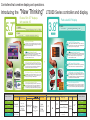
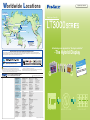
Worldwide Locations
Graphic Logic Controller
2 rue René Laennec 51500 Taissy France
Fax: 03 26 85 19 08, Tel : 03 26 82 49 29
Pro-face Europe B.V.
(European Head Office)
Pro-face
Northern Europe ApS
E-mail:[email protected]
Site web : www.hvssystem.com
Graphic Logic Controller
Pro-face
UK Ltd.
Pro-face
Deutschland GmbH
Pro-face
France S.A.S.
Pro-face Korea Co., Ltd.
Pro-face America, Inc.
Digital Electronics Corporation
Pro-face China
International Trading
(Shanghai) Co., Ltd.
Pro-face España
Pro-face Taiwan Co., Ltd.
Pro-face Italia S.p.a.
Pro-face India, Bangalore HQ
Pro-face South-East Asia
Pacific Co., Ltd.
International Pro-face
Pro-face Head Office
Pro-face Branch Office
Distributor or
Sales Representative
Pro-face Australia
Introducing a new approach to "the logic controller"
-The Hybrid Display
Our Environmental Policy and Compliance with the RoHS Directive
Pro-face has taken significant steps to meet increasingly stringent requirements for environmental preservation and has sought to comply with the RoHS
Directive by adopting measures to eliminate specified harmful substances from existing products and products to be manufactured and sold beginning in 2006.
For details, please refer to our web site or contact our sales office in your country.
Conformance with International Safety Standards
C A N o pen
)
tandard
( N e t w ork S
http://www.pro-face.com/worldwide/
Caution: Before operating any of these products, be sure to read all related manuals thoroughl y.
For printing purposes, the colors in this catalog may differ from those of the actual unit.
LCD screens may exhibit minute grid-points (light and dark) on the Display Panel surface.
"Contouring" - where some parts of the screen are brighter than others, producing a wavelike pattern may occasionally occur. Both are normal for an LCD display and are not defects.
Actual user screens may differ from the screens shown here.
All product names used in this catalog are the registered trademarks or trademarks of their respective companies.
All information contained in this catalog is subject to change without notice.
5.7
Pro-face is a registered trademark of Digital Electronics Corporation in
Japan, U.S.A., Canada, Europe and other areas and countries.
3.8
2010.11 Digital Electronics Corporation. All Rights Reserved.
Global Head Office
Australia and New Zealand
China
India
Digital Electronics Corporation
Osaka, JAPAN
Tel: +81 (0)6 6613 3116
Fax: +81 (0)6 6613 5888
http://www.pro-face.com
[email protected]
Pro-face Australia
Melbourne, AUSTRALIA
Tel: +61 (0)3 9550 7395
Fax: +61 (0)3 9550 7390
http://www.pro-face.com.au http://www.pro-face.co.nz
[email protected]
Pro-face China International Trading (Shanghai) Co., Ltd.
Shanghai, P. R. CHINA
Tel: +86 (0)21 6361 5175
Fax: +86 (0)21 6361 5176
http://www.proface.com.cn
[email protected]
Pro-face India
Bangalore, INDIA
Tel: +91 80 3066 7454/7456
Fax: +91 80 3066 7452
[email protected]
North/South American Head Office
South-East Asia Pacific
South Korea
Taiwan
Pro-face America, Inc.
Saline, MI U.S.A.
Tel: +1 734 429 4971
Fax: +1 734 429 1010
http://www.profaceamerica.com
[email protected]
Pro-face South-East Asia Pacific Co.,Ltd.
Bangkok, THAILAND
Tel: +66 (0)2 617 5678
Fax: +66 (0)2 617 5688
http://www.proface.co.th
[email protected]
Pro-face Korea Co., Ltd.
Seoul, SOUTH KOREA
Tel: +82 (0)2 2630 9850
Fax: +82 (0)2 2630 9860
http://www.proface.co.kr
[email protected]
Pro-face Taiwan Co., Ltd.
Taipei, TAIWAN
Tel: +886 (0)2 2657 1121
Fax: +886 (0)2 2657 1021
http://www.proface.com.tw
[email protected]
European Head Office
Austria
Spain and Portugal
Pro-face Europe B.V.
Hoofddorp, THE NETHERLANDS
Tel: +31 (0)23 55 44 099
Fax: +31 (0)23 55 44 090
http://www.proface.com
[email protected]
Pro-face Europe B.V.(Austria Office)
Hagenberg, AUSTRIA
Tel: +43 7236 3343-620
FAX: +43 7236 3343-629
http://www.pro-face.at
[email protected]
Pro-face Espa a
Cardedeu (Barcelona), SPAIN
Tel: +34 (0)93 846 07 45
Fax: +34 (0)93 845 48 68
http://www.pro-face.es
[email protected]
France
Germany
Russia
Pro-face France S.A.S.
Mitry-Mory, FRANCE
Tel: +33 (0)1 60 21 22 91
Fax: +33 (0)1 60 21 22 92
http://www.proface.fr
[email protected]
Pro-face Deutschland GmbH
Solingen, GERMANY
Tel: +49 (0)212 258 260
Fax: +49 (0)212 258 2640
http://www.pro-face.de
[email protected]
Pro-Face Northern Europe ApS (Saint-Petersburg office)
Saint-Petersburg, RUSSIA
Tel: +007 (812) 336-47-06
Fax: +007 (812) 336-47-18
http://www.pro-face.ru
[email protected]
Poland
Scandinavia, Baltic Countries
Italy
Pro-face Europe B.V.(Warsaw Office)
Warzawa, POLAND
Tel/FAX:+48 (22) 465-66-62
http://www.proface.pl/
[email protected]
Pro-face Northern Europe ApS
Roskilde, DENMARK
Tel: +45 70 22 01 22
Fax: +45 70 22 01 33
http://www.pro-face-eu.net/
[email protected]
Pro-face Italia S.p.a.
Bovisio Masciago (Milano), ITALY
Tel: +39 0362 59 96 1
Fax: +39 0362 59 96 69
http://www.proface.it
[email protected]
Switzerland
United Kingdom
Sweden
Pro-face Deutschland GmbH
Regensdorf, SWITZERLAND
Tel: +41 (0)43 343 7272
Fax: +41 (0)43 343 7279
http://www.pro-face.ch
[email protected]
Pro-face UK Ltd
Coventry, ENGLAND
Tel: +44 (0)2476 511288
Fax: +44 (0)2476 511499
http://www.profaceuk.com
[email protected]
Pro-face Sweden AB
L ddek pinge (Malm ), SWEDEN
Tel: +46 46 540 90 70
Fax: +46 46 71 27 90
http://www.pro-face-eu.net
[email protected]
F
OF
C O N T R O L
DS/DS0807-LT3000ALL-03cE06
ON
O P E R A T I O N
D I S P L A Y
Controllers that combine display and operations.
"New Thinking"
Introducing the
5.7"
QVGA
Feature Rich 5.7" displays
with scalable I/O
Palm-sized 3.8" display
LT-3300S/L
STN Color 4,096
colors / Monochrome16 shades DIO 32 points
3 Expansion Slots
USB
SIO
Ethernet
3.8"
LT-3201A
Monochrome
DIO18 Points
8 shades
16 shades
DIO 32 points
3 Expansion Slots
USB
Up To 50 I/O Connections
32 built-in I/O points are standard. These can be used for
special I/O such as pulse outputs. By adding 3 EX modules,
you can have up to 80 points.
Useful
Offers compact size with 18 built-in I/O points. This can be
used for special I/O such as pulse outputs. By adding 2 EX
modules, you can have up to 50 points.
(Network Standard)
(Network Standard)
EN50325-4 Network Standard. LT3000 supports CANopen.
Expandable Using the LT as a master, you can connect to I/O
equipment on the CANopen network. See our support site
for recommendation slave units.
Expandable
USB / Ethernet Ports and Data Collection
Ease of Use
data with ease. Real-time collection and management of
production data is possible over the network.
In addition to the monochrome display, you can use the
4,096 color STN model. Its 5.7" screen allows you to
fully express your images in brilliant colors.
Brilliant
Reduced Development Time
Effortless
for the beginner developers the program is easy to use,
as it utilizes drag and drop operations for drawing and setting up.
C ontroller
Expansion Units * Exclusive use only
EX Modules
CANopen
Di s p l a y
Controller Memory
Serial Port USB (host) Port Ethernet Port
32 points
Inputs: 16 Outputs: 16
Pulse Output
Max.65kHz
3 EX Modules Max.
Up to 48 Inputs / Outputs
Counter Input
LT-3301L
LT-3201A
01
Display Type
Resolution Display Size
4,096 STN Colors
LT-3300S
LT-3300L
Program your ladder logic, user interface and communication settings all
in a single application. Even for the beginner developer’s programming is
easy, as it uses convenient drag and drop fordrawing and configuration.
Switches between amber and red.
Color and monochrome models.
* Uses built-in DIO s four points.
Even though the screen is small, do not limit yourself to text.
You can display graphics and images beautifully on the screen.
The backlight also allows you to switch between amber and
red to indicate alarms and other conditions.
Reduce Development Time
You can program ladder logic, draw the screen interface,
Effortless and set up communication, all in a single application. Even
Special I/O
The USB port comes standard. This enables using USB memory
to collect and transmit screen and production data with ease.
Full Graphics in a Compact Display
Full Graphics Displays in Beautiful Color
Brilliant
EN50325-4 Network Standard. LT3000 supports CANopen.
Using the LT as a master, you can connect to I/O equipment
on the CANopen network. See our support site for
recommendation slave units.
USB Port and Data Collection
The USB port comes standard. This enables using USB
Ease of Use memory to collect and transmit screen and production
Built-in DIO
Max.100kHz
18 points
Inputs: 12 Outputs: 6
USB
SIO
Up to 80 I/O Points
Useful
Product Name
2 Expansion Slots
QVGA
LT-3301L
Monochrome
LT3000 Series controller and display.
2 EX Modules Max.
Up to 32 Inputs / Outputs
63 Stations
Bit Inputs / Outputs :
1024
Integer Inputs / Outputs :
256
FLASH
EPROM
132KB
Monochrome 16 Shades
LT-3300S
QVGA
5.7"
−
Equivalent to 15,000 Steps
(Up to 60,000 Steps)
−
−
P roduct N ame
LT-3300L
LT-3301L
Monochrome 8 Shades
(Amber / Red)
3.8"
LT-3201A
02
Expandable
Reduce Equipment Space While Expanding Capabilities
Handle data in the field without a PC
USB
With a USB memory stick, you can update screens, retrieve production data, as well as change
passwords and labels.
Possible because
5.7" model
With LT-3300S/L
connects.
Manage production data in real-time
Ethernet
Using a PC you can set up accurate and efficient
production controls, such as automating work
instructions or collecting real-time production data.
Serial (RS-232C / 422 / 485)
With LT-3300S/L and LT-3301L
Direct connections to temperature controllers without a PLC
EX Modules / CANopen Master Unit
Previously, a PLC was needed to connect to a temperature controller. With the 5.7" model, use the serial interface to
connect to a temperature controller or other types of boards, thereby reducing your overall equipment cost.
DIO
Check logic operations without a PC
Enhanced Control Features for a Variety of Devices
IN
[DC, High-Speed Counter, Pulse Catch inputs]
[DC, Analog, Temperature inputs]
[Connect to CANopen-supported slave units]
Built-in DIO
EX Modules
CANopen
Limit Switch
Encoder
Sensor
Emergency Button Thermometer
[Transistor, Pulse, PWM outputs]
[Transistor, Relay, Analog outputs]
[Connect to CANopen-supported slave units]
DIO
OUT EXBuilt-inmodules
CANopen
Pump
Solenoid Valve
* EX modules only
Stepping
Motor
Motor
Drive
(Standard feature)
Control the speed of a conveyor with a
s t e p p i n g m o t o r. C o n n e c t d i r e c t l y t o a
temperature controller using serial
communication to eliminate the need for a PLC.
Cleaning machine
Address Monitor
Display the whole ladder
program.
You can check the operation
status and logic program.
Displays addresses used in
the ladder program.
Displays variables and their
current values.
Flow Rate / Pressure
Analog Input / Output
(Standard feature)
Control the flow to a tank or its temperature
with analog I/O and temperature inputs.
Even with reduced space,interactive
operation is improved with the touch
panel.
Serial
LT3000
Motor
driver
out
Valve control
in
Detergent
Thermometer
Valve control
Cleaning
Valve control
out
LT3000
Packing machine
START/STOP Control
LT3000
Inverter
in
Alarm and valve control
Encoder
Stepping
motor
03
in
Sensor
Cooling water
Temperature input
Feed roller
Analog input or
high-speed counter
Cutter
Tape
Analog output
PRECISION!
Delivery lockers
Password input
Sensor
Sensor
Sensor
out
Key
Detecting sensor
C E R TA I N T Y !
Expansion modules enable adding I/O
as the number of lockers increases.
Of course, with password keys you can
lock and unlock lockers.
LT3000
in
out
Cutter control
Motor
Detecting sensor
Heat exchanger
Dehydrating
Drying
Conveyer
Detecting sensor
Sensor and control valve
Coolant Circulator
Water level sensor
Ethernet
out
DIO Expansion
Module (EX Module)
(EX Module)
in / out
Pulse output
P.05
the LT3000 Series you can do all this and more.
100 kHz High-Speed
Counter
Control an inverter by entering positional
information with an encoder. Gather real-time
production information and control with precision.
More!Simple programming
enables you to cut work hours.
For details, see
* EX modules only
Still relying on PLCs, switches and lamps? With just
65 kHz Pulse Output
Logic Monitor
Circulation pump
Key
Key
Key
Circulating cooling water
Flow rate
controller
Circulating pump control
SCALABLE!
PERFECTION!
04
[Instruction Notation List]
Logic programming and HMI drawing all in one soft ware
reduces development time.
Added functionality to coordinate logic program and HMI development. Drag and drop parts or instructions
between the logic and drawing editors to map symbols/variables to newly created instructions or parts. This
coordination between the editors allows for efficient development of your HMI screens and logic programs,
thereby reducing time of development.
Editing made easy!
Define PLC / Device Addresses
You can use device addresses of connected equipment
directly in the logic program. This simplifies interlock and
other features.
Subroutine Blocks
You can set up the initialization logic, main logic, and
subroutines as blocks so that editing proceeds smoothly.
Drag and Drop
Drag and drop between the drawing and logic screens.
Number of Steps
The program size is made obvious by displaying the
number of steps. Normal capacity is 15,000 steps. By
using the program area, you can increase this to 60,000
steps. However, this reduces the screen data capacity to
1 MB.
Displaying Comments
Popping up comments as tool tips makes the logic easy to
follow. Optionally, you can choose to display comments
all the time.
"Drag and Drop" For Easy Settings
Mapping I/O with Drag and Drop
Drawing a switch / lamp on the screen
From Ladder Instruction
From Ladder Instruction
From Parts Toolbox
From Symbol Variable List
Useful Features For Reducing Costs
GP-Pro EX Simulation
Without transferring data to the LT unit, you can debug the screen
data and logic program on your PC. Entering device address
values, you can simulate the environment of external devices.
Alarm Log
When an alarm is triggered, its associated alarm message and
register value are collected. You can choose to investigate the
cause of the alarm right away, or save the information to a CSV
file and analyze the information later on the PC.
Project Converter
When working with LT-330*S/L units, you can convert LogiTouch
screen data and logic programs (built-in DIO) created in
C-Package. This feature enables you to re-use previous assets.
05
* There is a limit to the amount of compatibility. Please speak to a sales contact
or visit our homepage for details.
Operation Log
Record operation information such as "Who", "When", and "How",
so this information can be used to investigate the origin of any
errors.
Historical Graph
Displays data collected over time in a graph. You can specify the
time to jump to a particular location in the graph, or simply scroll
to view past data.
Online Edit
Even while the logic program is running, you can edit the logic
without stopping it.
Available Editing Features
- Insert or delete rungs, instructions, labels and rows
- Edit operands
06
Product Specifications
Hardware
LT-3300S/L
5.7"
QVGA
STN Color
Performance Specifications
Display Type
Display Colors/Shades
LT-3300S
Sink Output
Ethernet
Monochrome
Sink Output Model:LT3301-L1-D24-K
Monochrome
Source Output Model:LT3301-L1-D24-C
STN Color
Source Output
Ethernet
Model:LT3300-S1-D24-C
Sink Output
Ethernet
Model:LT3300-L1-D24-K
Monochrome
Source Output
Ethernet
Model:LT3300-L1-D24-C
General Specifications
LT-3301L
Monochrome LCD
Black and White (16 shades) (3-speed blink)
STN Color LCD
4,096 colors (3-speed blink)
Model:LT3300-S1-D24-K
Monochrome
LT-3300L
International Safety Standards
White LED (When replacement is required, contact your local distributor.)
Backlight
Conforming Standards
Display Resolution
Input Voltage
Rated Voltage
Effective Display Area
Brightness Control
Contrast Adjustment
8 levels of adjustment available via touch panel
Allowable Voltage
8 levels of adjustment available via touch panel
Power Consumption
Japanese: 6,962 (JIS Standards 1 & 2 including 607 non-kanji characters)
ANK:158 *1
Language Fonts
Stroke font: 6 to 127 dot fonts
dots
dots
dots
Touch Panel Type
Atmosphere
Air Pressure Resistance (Availment Altitude)
Noise Immunity
(via nose simulator)
Electrostatic Discharge Immunity
Grounding
IEEE802.3u 10BASE-T/100BASE-TX
Ratings
−
RS-232C / 422 / 485, Asynchronous Transmission, Data Length: 8 bit / 7 bit
Stop Bit: 2 bit / 1 bit, Parity: Even / Odd / None,
Data Transmission Speed: 2400bps-115.2kbps Connector: D-Sub 9pin plug
Serial
Interface
Vibration Resistance
FLASH EPROM 132KB *5
15,000 steps *6
Number of Step
Ethernet
USB 1.1 Connector: Type A x 1, Power Supply Voltage: DC5V 5%,
Output Current: 500mA (max.), Communication Distance: 5m (max.)
USB
DIO (Sink Type)
Sink / Source Input: 16 points, Sink Output: 16 points
Connector: 38 pins
Control
(DIO) DIO (Source Type)
Sink / Source Input: 16 points, Source Output: 16 points
Connector: 38 pins
To mount EX Module *7
EX Module (EXT1)
AUX / Expansion Unit (EXT2)
*8
Pollution Degree
SRAM 128KB *4
SRAM 64KB *4
Backup Memory
Variable Area
Control Memory
Program Area
Rated Voltage
Allowable Voltage
Sink Output
Output Method
Source Output
Maximum Load Voltage
Minimum Load Current
Output Voltage Drop
OFF to ON
Output Delay Time
ON to OFF
Voltage Leakage (When OFF)
Clamp Voltage
Type of Output
Common Lines
Common Design
External Connection
Output Protection Type
Internal Fuse
Surge Control Circuit
Output Points
Output Signal Display
Isolation Method
External Power Supply
Humidity
FLASH EPROM 6MB *3
Internal Memory
To mount CANopen Master Unit *7
DC24V
External
Power Supply
Internal Circuit
Dotted area indicates the cable diagram with sink output type devices.
[Output Circuit]
(Sink Type)
External Dimensions
Weight
*1 Korean, Simplified Chinese, Traditional Chinese, Cyrillic and Thai character support. For more
information, see the operation environment for GP-Pro EX.
*2 Using the software, you can resize characters.
*3 User area.
o
*4 Service life of a lithium battery is 10 years or more at a battery ambient temperature of 40 C or less,
o
o
4.1 years or more at 50 C or les, or 1.5 years at 60 C or less. The backup period is about 100 days after
the initial charge (fully charged), and about 6 days up to the end of battery life.
*5 Using Pro-face s Step counting method.
*6 Up to 60,000 steps can be made, but this reduces the capacity of the internal screen data memory by 1MB.
*7 EX Module and CANopen Master Unit cannot be used at the same time.
*8 Temperature in and around the panel. For STN color models, extended use in environments where the
o
surrounding air temperature is 40 C or higher may degrade the display quality and could result in
decreased contrast.
*9 Confirmed compatibility under conditions. This does not guarantee compatibility for all environments.
0.5ms or less (with output DC24V, 200mA)
0.5ms or less (with output DC24V, 200mA)
Internal circuit
*For faster response with light load use an external dummy resistance.
[Output Circuit]
Input Points
Internal circuit
77.6 [3.06]
5 [0.19]
+0.04
]
156.0 +1
- 0 [6.14 - 0
Allowable Panel Thickness:
1.6 [0.06] to 5.0 [0.20]
Internal circuit
Pulse Catch
DC24V
Open Collector
Internal circuit
IN0, IN2,
IN4, IN6
* For faster response with light load use an external dummy resistance.
User Defined
User Defined
Input signal ON width
Pin Connection
39
[1.54]
t
t
90 degree phase differential 2-phase signal /
1 Phase
1-phase +directional signal
50Kpps
100Kpps
Not Available
Available
32-bit UP / DOWN Counter
Set through software
Not Available
Available
IN3,IN7
None
Depending on type of connection cable used the dimensions shown above will change.
The dimensions given here are representative values and are intended for reference only.
Output Points
Load Voltage
Minimum Load Current
Maximum Output Frequency
Pulse Acceleration
ON Duty
B1
−
−
−
−
−
−
−
−
A10
A11
A19
4 points
PLS0 to PLS3 (OUT0 to OUT3) PWM0 to PWM3 (OUT0 to OUT3)
User Defined
User Defined
DC24V
1mA
Max.65kHz(set through software)Varies depending on the number of CH of High-speed counter, pulse output
Not Available
Available
19 to 81% (at 65kHz)*12
50% 10% (at 65kHz)*11
[System Structure]
B19
(Cable side)
A12
A13
A14
A15
A16
A17
A18
A19
Signal Name
IN1
IN3
IN5
IN7
IN9
IN11
IN13
IN15
NC
Sink output type: NC
Source output type: +24V
Sink output type: 0V
Source output type: NC
OUT1 (PLS1, PWM1)
OUT3 (PLS3, PWM3)
OUT5
OUT7
OUT9
OUT11
OUT13
OUT15
Pin No. Signal Name
B1
IN0 (CT0)
B2
IN2 (CT1)
B3
IN4 (CT2)
B4
IN6 (CT3)
B5
IN8
B6
IN10
B7
IN12
B8
IN14
B9
COM
Sink output type: +24V
B10
Source output type: +24V
Sink output type: 0V
B11
Source output type: 0V
B12
OUT0 (PLS0, PWM0)
B13
OUT2 (PLS2, PWM2)
B14
OUT4
B15
OUT6
B16
OUT8
B17
OUT10
B18
OUT12
B19
OUT14
*10 Digital filter can be set intervals of 0.5ms.
*11 The ON duty error (10%) reduces as the output frequency setting is lower.
*12 ON duty (effective range) increases as the output frequency setting is lower.
[Editor Environment]
USB Interface
Barcode Reader*1
(Commercial type)
Ethernet Interface
DIO Interface
USB Storage *1
Hub
(Commercial type)
PC
(Commerciall type)
USB-IEEE1284
Conversion cable
(Commercial type)
Serial Interface
DIO Cable
PC
(Commercial type)
Various I/O devices,
indication lights,
LED sensors,
switches, etc.
CA5-USBEXT-01
USB Hub
(Commercial type)
RS422 Cable (5m)
Temperature
Contoller
Various boards*1
Barcode Reader*1
(Commercial type)
COM Pot Conversion Connector Terminal Block
Adapter
Conversion Adapter
USB Interface
EX Module
(max. 3 units)
Modem *1
USB Transfer Cable
CA3-USBCB-01
AUX/Expansion Unit Interface (EXT2)
RS422 Cable
(Prepared by the user)
CA3-ADPCOM-01 CA3-ADPTRM-01
For Isolation Unit, see manuals for system diagrams.
CANopen Master Unit
Screen Creation Software
GP-Pro EX
*2
CA3-CBL232/5M-01
CA3-CBL422/5M-01
USB Front Cable
*Except for LT-3301L
(Prepared by the user)
RS-232C Cable (5m)
(Commercial type)
Ethernet Interface
CA7-DIOCN5-01
(Commercial
type)
FP-US00 or commercial type
CA6-USB232-01
DIO Connector
(included in the package)
EX Module Interface (EXT1)
Printer *1
USB Cable
USB-Serial (RS-232C) Conversion Cable
Various I/O devices,
indication lights,
LED sensors,
switches, etc.
*Except for LT-3301L
(Commercial type)
07
A1
A2
A3
A4
A5
A6
A7
A8
A9
−
PWM
Pulse
Output Method
LT-3301L does not support Ethernet Interface.
LT-3301L does not support Ethernet Interface.
The maximum thickness when three EX modules are
connected:123.0mm [4.84in.].
Pin No.
Minimum Pulse Width
(Pulse Input)
Pulse/PWM Output Specifications
63 [2.48]
64 [2.52]
AUX / Expansion Unit (EXT2)
Interface
USB(host)Interface
Serial Interface
31 [1.22]
98 [3.86]
144.6 [5.70]
DIO Interface
Ethernet Interface
4/R3 [0.12]
or less
123.5 +1
-0 [4.86]
EX Module (EXT1)
Interface
134.6 [5.30]
123 [4.84]
Display/ Touch Panel
135 [5.31]
167.4 [6.59]
OUT0 to 3 only
Dummy Resistance*
Fuse
3.5A
User Defined
Phase
High Speed Count Frequency
Count Edge Designation
Count Register
Counter Mode Change
Upper/Lower Limit Settings
Preload/Prestrobe
Marker Input (Clear Counter Value)
Unit: mm [in.]
DC24V
External
Power Supply
Internal circuit
(Rise, Fall Time)
[Cable Attached Dimensions]
Unit: mm [in.]
Fuse
3.5A
(Source Type)
High-speed Counter
DC24V Open Collector
Double phase (1 or 2 points)
Single phase (4 points)
Use CT0 (IN0),
CT0 (IN0),
CT1 (IN2) in pairs.
CT1 (IN2),
CT0:
Phase
A, CT1: Phase B
CT2 (IN4),
CT2 (IN4), CT3 (IN6) in pairs.
CT3 (IN6),
CT2: Phase A, CT3: Phase B
Input
OUT0 to 3 only
Dummy Resistance*
1mA (Pulse/PWM Output Unavailable)
High-speed Counter / Pulse Catch Input Specifications
Cooling Method
[Panel Cut-Out]
DC24V
External
Power Supply
Fuse
3.5A
Internal circuit
A1
Unit: mm [in.]
Fuse 3.5A
Internal circuit
Count Speed
[External Dimensions/Interfaces]
Internal Circuit
OUT4 to OUT15
Storage Temperature
Storage Humidity
Touch Panel Resolution
[Input Circuit]
Internal circuit
Surrounding Air Temperature
Standard font: Increase Width and Height up to 8 times. *2
40 char. x 30 rows
40 char. x 15 rows
20 char. x 15 rows
10 char. x 7 rows
Resistive Film (Analog)
Font Sizes
dots
Rated Voltage
DC24V
Maximum Allowable Voltage
DC28.8V
Input Method
Sink / Source Input
Rated Current
6.5mA (DC24V) (IN0, IN2, IN4, IN6) 4.1mA (DC24V) (Other inputs )
Input Resistance
Approx.3.7k (IN0, IN2, IN4, IN6) Approx.5.9k (Other inputs)
Input Points
16
Common Lines
1
Common Design
16 points / 1 common line
ON Voltage
DC19V or more
Operation Range
OFF Voltage
DC5V or less
OFF to ON
0.5 to 20ms *10
Input Delay Time
ON to OFF
0.5 to 20ms *10
Input Signal Display
No LED indicators
Isolation Method
Photocoupler Isolation
External Connection
38-pin connector (used with Output section)
External Power Supply
For Signal: DC24V
Output Specifications
Voltage Endurance
Insulation Resistance
dot
Character Sizes
Text
Input Specifications
LT-3301L
*2
Transfer Cable
(CANopen standards)
Commercial type
Slave Unit
for CANopen *1
*1 For supported models, refer to Pro-face’s support site "Otasuke Pro!"(http://www.pro-face.com/otasuke/).
USB Storage
With the memory loader tool,the screens can be
transferred via USB storage.
(Commercial type)*1
*2 EX Module and Expansion unit cannot be used at the same time.
08
Hardware
Product Specifications
Input Specifications
LT-3201A
3.8"
QVGA
Monochrome
Sink Output
Model:LT3201-A1-D24-K
Monochrome
Source Output
Model:LT3201-A1-D24-C
Performance Specifications
LT-3201A
Display Type
Monochrome Amber / Red LCD
Display Colors/Shades
Backlight
General Specifications
International Safety Standards
Black and White (8 shades)
Amber / Red LED (When replacement is required, contact your local distributor.)
Conforming Standards
Display Resolution
Input Voltage
Rated Voltage
Effective Display Area
8 levels of adjustment available via touch panel
Brightness Control
Contrast Adjustment
8 levels of adjustment available via touch panel
Font Sizes
dots
dots
Voltage Endurance
Insulation Resistance
dots
dots
Surrounding Air Temperature
Ambient Humidity
Storage Temperature
40 Char. x 30 rows
40 Char. x 15 rows
Storage Humidity
20 Char. x 15 rows
Atmosphere
Air Pressure Resistance (Availment Altitude)
Pollution Degree
10 Char. x 7 rows
Resistive Film (Analog)
Touch Panel Resolution
Internal Memory
FLASH EPROM 6MB *3
Backup Memory
Variable Area
SRAM 128KB *4
SRAM 64KB *4
Program Area
FLASH EPROM 132KB *5
Noise Immunity
(via noise simulator)
Electrostatic Discharge Immunity
15,000 steps*6
Number of Step
Grounding
External Dimensions
Weight
Serial
−
USB
USB 1.1 Connector: Type A x 1, Power Supply Voltage: DC5V 5%,
Output Current: 500mA (max.), Communication Distance: 5m (max.)
Sink / Source Input: 12 points, Source Output: 6 points
Connector: 22 pins
To mount EX Modules *7
To mount CANopen Master Unit *7
EX Module (EXT1)
AUX / Expansion Unit (EXT2)
[External Dimensions / Interfaces]
Unit:mm [in.]
AUX/Expansion Unit (EXT2)
Interface
USB(host) Interface
Allowable Panel Thickness:
1.6 [0.06] to 5.0 [0.20]
Input
Input Points
The maximum thickness when two EX modules are connected:
96.8 mm [3.81 in.]
(Sink Type)
Unit: mm [in.]
above will change. The dimensions given here are representative
values and are intended for reference only.
OUT4 B11
OUT3 A10
OUT2 B10
OUT1 A9
OUT0 B9
Internal Circuit
0.5ms or less (with output DC24V, 200mA)
0.5ms or less (with output DC24V, 200mA)
L
L
* For faster response with light load use an external dummy resistance.
(Source Type)
Fuse 2.5A
Pulse Catch
DC24V
Open Collector
IN0, IN2,
IN4, IN6
OUT4 B11
OUT3 A10
OUT2 B10
OUT1 A9
OUT0
B9
L
Internal Circuit
+
-
DC24V
External
Power Supply
OUT0 to 3 only
Dummy Resistance*
0V A8
* For faster response with light load use an external dummy resistance.
User Defined
User Defined
t
+24V B8
OUT5
A11
L
Internal Circuit
1 Phase
Pin Connection
t
90 degree phase differential 2-phase signal /
1-phase +directional signal
50Kpps
Not Available
32-bit UP / DOWN Counter
Set through software
Not Available
Available
IN3, IN7
None
100Kpps
Available
−
−
−
−
−
−
−
−
−
Pulse / PWM Output Specifications
Load Voltage
Minimum Load Current
Maximum Output Frequency
Pulse Acceleration
ON Duty
DC24V
External
Power Supply
- +
[Output Circuit]
Input signal ON width
Output Points
0V A8
OUT0 to 3 only
Dummy Resistance*
User Defined
High Speed Count Frequency
Count Edge Designation
Count
Register
Counter Mode
Change
Upper / Lower Limit Settings
Preload/Prestrobe
Marker Input (Clear Counter Value)
Depending on type of connection cable used the dimensions shown
Fuse 2.5A
Minimum Pulse Width
(Pulse Input)
Output Method
DIO Interface
Dotted area indicates the cable diagram with sink output type devices.
[Output Circuit]
1mA (Pulse / PWM Output Unavailable)
High-speed Counter
DC24V Open Collector
Single phase (4 points)
Double phase (1 or 2 points)
Use CT0 (IN0),
CT0(IN0),
CT1(IN2) in pairs.
CT1(IN2),
CT0: Phase A, CT1: Phase B
CT2(IN4),
CT2(IN4),CT3(IN6) in pairs.
CT3(IN6),
CT2: Phase A, CT3: Phase B
Phase
4/R3 [0.12]
or less
+0.04
+1
]
92.5 - 0 [3.64 - 0
92 [3.62]
21.5[0.85]
5 [0.20]
21.5 [0.85]
104 [4.09]
Display/Touch Panel
+1
+0.04
118.5 -0 [ 4.67 - 0 ]
EX Module (EXT1)
Interface
Internal Circuit
OUT5 A11
Count Speed
(Rise, Fall Time)
[Cable Attached Dimensions]
Unit: mm [in.]
76.5 [3.01]
130 [5.12]
Internal Circuit
IN11 A6
IN10 B6
IN9 A5
IN8 B5
IN7 A4
IN6 B4
IN5 A3
IN4 B3
IN3 A2
IN2 B2
IN1 A1
IN0 B1
Internal Circuit
High-speed Counter / Pulse Catch Input Specifications
*1 Korean, Chinese (Simplified) and Chinese (Traditional),Cyrillic and Thai character support. For more information,
see the operation environment for GP-Pro EX.
*2 Using the software, you can resize characters.
*3 User area.
o
*4 Service life of lithium battery is 10 years or more at a battery ambient temperature of 40 C or less,
4.1 years or more at 50oC or less, 1.5 years at 60oC or less. The backup period is about 100 days after
the initial charge (fully charged), and about 6 days up to the end of battery life.
*5 Using Pro-face s Step counting method.
*6 Up to 60,000 steps can be made, but this reduces the capacity of the internal screen data memory by
1MB.
*7 EX Module and CANopen Master Unit cannot be used at the same time.
*8 Temperature in and around the panel.
*9 Confirmed compatibility under conditions. This does not guarantee compatibility for all environments.
[Panel Cut-out]
- +
+24V B8
Rated Voltage
Allowable Voltage
Sink Output
Output Method
Source Output
Maximum Load Voltage
Minimum Load Current
Output Voltage Drop
OFF to ON
Output Delay Time
ON to OFF
Voltage Leakage (When OFF)
Clamp Voltage
Type of Output
Common Lines
Common Design
External Connection
Output Protection Type
Internal Fuse
Surge Control Circuit
Output Points
Output Signal Display
Isolation Method
External Power Supply
Cooling Method
Sink / Source Input: 12 points, Sink Output: 6 points
Connector: 22 pins
Sink Output
Control (Model: LT3201-A1-D24-K)
(Built-in DIO) Source Output
(Model: LT3201-A1-D24-C)
*9
Ratings
−
Ethernet
Interface
Vibration Resistance
82 [3.23]
98 [3.86]
Touch Panel Type
Control Memory
*8
86 [3.39]
Text
COM
+ - B7
OUT4 to OUT15
Power Consumption
dot
Stroke font: 6 to 127 dot fonts
Standard font: Width and Height can be expanded up to 8 times.*2
Character Sizes
DC24V
External
Power supply
Output Specifications
Allowable Voltage
Japanese: 6,962 (JIS Standards 1 & 2 including 607 non-kanji characters)
ANK: 158 *1
Language Fonts
[Input Circuit]
DC24V
DC28.8V
Sink / Source Input
6.5mA (DC24V) (IN0, IN2, IN4, IN6) 5mA (DC24V) (Other inputs)
Approx.3.7k (IN0, IN2, IN4, IN6) Approx.4.7k (Other inputs)
12
1
12 points / 1 common line
DC19V or more
DC5V or less
0.5 to 20ms *10
0.5 to 20ms *10
No LED indicators
Photocoupler Isolation
22-pin connector (used with Output section)
For Signal: DC24V
Rated Voltage
Maximum Allowable Voltage
Input Method
Rated Current
Input Resistance
Input Points
Common Lines
Common Design
ON Voltage
Operation Range
OFF Voltage
OFF to ON
Input Delay Time
ON to OFF
Input Signal Display
Isolation Method
External Connection
External Power Supply
Pulse
PWM
4 points
PLS0 to PLS3 (OUT0 to OUT3) PWM0 to PWM3 (OUT0 to OUT3)
User Defined
User Defined
DC24V
1mA
Max.65kHz(set through software)Varies depending on the number of CH of High-speed counter, pulse output
Available
Not Available
50% 10% (at 65kHz)*11
19 to 81% (at 65kHz) *12
[System Structure]
A1
A11
B1
B11
(Cable Side)
Pin No.
Signal Name
Pin No.
Signal Name
A1
IN1
B1
IN0(CT0)
A2
IN3
B2
IN2(CT1)
A3
IN5
B3
IN4(CT2)
A4
IN7
B4
IN6(CT3)
A5
IN9
B5
IN8
A6
IN11
B6
IN10
A7
NC
B7
COM
A8
0V
B8
+24V
A9
OUT1 (PLS1, PWM1)
B9
OUT0 (PLS0, PMW0)
A10
OUT3 (PLS3, PWM3)
B10
OUT2 (PLS2, PWM2)
A11
OUT5
B11
OUT4
*10 Digital filter can be set intervals of 0.5ms.
*11 The ON duty error (10%) reduces as the output frequency setting is lower.
*12 ON duty (effective range) increases as the output frequency setting is lower.
[Editor Environment]
USB Interface
Barcode Reader*1
DIO Interface
Various I/O devices,
indication lights,
LED sensors,
switches, etc.
(Commercial type)
USB Storage*1
(Commercial type)
USB-IEEE1284
Conversion Cable
(Commercial type)
DIO Cable
DIO Connector
(Provided by the user)
(included in the package)
(Commercial type)
CA3-USBCB-01
Various I/O devices,
indication lights,
LED sensors,
switches, etc.
FP-US00 or Commercial type
Modem *1
(Commercial type)
PC
(Commercial type)
Screen Creation Software
GP-Pro EX
EX Module Interface (EXT1)
USB Cable
USB-Serial (RS-232C)
Conversion Cable
USB Transfer Cable
CA6-DIOCN4-01
Printer *1
USB Interface
USB Storage
EX Module
(max.2 units)
With the memory loader tool, the screens can be
transferred via USB storage.
(Commercial type) *1
CA6-USB232-01
USB Front Cable
Barcode Reader*1
CA5-USBEXT-01
(Commercial type)
USB Hub
(Commercial type)
CANopen Master Unit
09
Transfer Cable
(CANopen standards)
Commercial type
Slave Unit
for CANopen *1
*1 For supported models, refer to Pro-face’s support site "Otasuke Pro!"(http://www.pro-face.com/otasuke/).
*2 EX Module and Expansion unit cannot be used at the same time.
10
Hardware
EX Module / CANopen Master Unit Specification / Option Item List
[Input Module]
[Option Item List]
Product Name
Rated Input Current
7.3mA / 1 point (DC24V)
Input Impedance
Between input terminals and internal circuit: photocoupler isolated Between input terminals: not isolated
Input Delay Time
OFF-ON: 4ms ON-OFF: 4ms
External Connection
10-pin terminal connector
Status LED
LED is lighting when input is ON.
Power Consumption *1
0.17W or less
0.27W or less
Weight
85g [0.19lb]
100g [0.2lb]
EXM-DRA8RT
EXM-DRA16RT
8-point relay (a-connect)
Output Points
16-point relay (a-connect)
Rated Output Voltage
3
4
5
Voltage
1 common
EXM-DDO16UK
EXM-DDO16TK
8-point t ransistor (sink)
8-point t ransistor (source)
16-point t ransistor (sink)
16-point t ransistor (source)
6
7
8
9
10
8 points / 1 common
8 points / 1 common
2A or less
7A or less
8A or less
16 points / 1 common
0.3A or less
0.1A or less
3A or less
1A or less
0.1mA / DC0.1V (reference value)
Minimum Load Current
Electrical Life
100,000 operations or more (no load 1,800 operations/h)
Mechanical Life
20 milion operations or more (no load 18,000 operations/h)
11
12
−
13
Output Delay
ON
6ms or less
14
Time
OFF
10ms or less
Isolation Method
Voltage Leakage
−
15
11-pin terminal connector
10-pin terminal connector
Power Consumption *1
1.16W or less
2.10W or less
0.55W or less
1.03W or less
Weight
110g [0.24lb]
145g [0.32lb]
85g [0.19lb]
70g [0.15lb]
External Connection
10-pin terminal connector
Status LED
MIL connector
LED is lighting when output is ON
EXM-AMI2HT
EXM-DMM8DRT
Input Points
4 points (sink / source type-dual use)
Input Points
Rated Input Voltage
DC24V
External Connection
Rated Input Current
7.3mA / DC24V
Input Type
OFFーON: 4ms
ONーOFF: 4ms
Output Points
4-point relay(a-connect)
EXM-ALM3LT
EXM-AMO1HT
Voltage (0-10V), Current (4-20mA)
Type K 0.325 o C
Input Value of LSB
−
o
Type J 0.300 C
Type T 0.100 o C
min.1M (voltage input), 10 (current input)
−
min.1M
Common Design
4 points / 1 common
Isolation Method
Between input terminals and internal circuit: photocoupler isolated
−
2A or less
Sampling Time
20ms or lesss
−
7A or less
Total Input System Transfer Time
0.1mA / DC0.1V
Maximum Error
100,000 operations or more
Output Points
−
Output Type
−
Minimum Load Current
Electrical Life
Mechanical Life
Output Delay Time
Output Specification
(no load 1,800 operations/h)
20 million operations or more
(no load 18,000 operations/h)
ON
6ms or less
OFF
10ms or less
External Connection
11-pin terminal connector
200ms + 1 scan time
105ms + 1 scan time
Resolution
−
Output Value of LSB
−
Output Impedance
−
Isolation Method
−
Total Output System Transfer Time
−
Maximum Error
−
Description
USB cable for transferring data such as screen data (host to host)
Connects a USB peripheral unit. (host to slave)
The cable for extending the LT s USB port
The conversion cable for using a LT’s USB I/F as the Serial (RS-232C) I/F. Connects a Modem only for the RS-232C communication method.
Interface cable for communication between a temperature controller/various boards and the LT series via RS-232C.
For 5.7"
Interface cable for communication between a temperature controller/various boards and the LT series via RS-422.
For 5.7"
Interface cable for communication between a temperature controller/various boards and the LT series via RS-422. <for a unit of terminal resistance 100 >
For 5.7"
Pin assign conversion adapter connects optional RS-422 communication items to LT-3300 series unit s COM1 port.
For 5.7"
Conversion adapter converts a COM port to RS-422 terminal block.
For 5.7"
Unit for providing isolated connection between a temperature controller/various boards and the LT series. RS-232C and RS-422 are switchable.
For 5.7"
8-point sink-source shared expansion unit
8-point relay output / 2-point common type expansion unit
8-point transistor output sink type expansion unit
8-point transistor output source type expansion unit
16-point sink-source shared expansion unit
16-point relay output / 2-point common type expansion unit
16-point transistor output sink type expansion unit
16-point transistor output source type expansion unit
4-point input sink-source / 4-point relay output / 1 common mixed I/O unit
2-ch analog input type expansion unit
2-ch temperature input / 1-ch analog output type expansion unit
2-ch analog input / 1-ch analog output expansion unit
1-ch analog output type expansion unit
Master unit to connect to a slave unit supporting CANopen
Slave unit supporting CANopen with 12 digital inputs, 6 relay outputs and 2 transistor source outputs. Up to 7 units of EX modules can be connected.
For 5.7"
For 3.8"
For 5.7"
For 5.7"
Disposable, dirt-resistant sheet for the LT unit s screen (5 pcs/set)
Regarding grease and chemical application, do not remove the unit, simply replace the environmental protection cover (5 pcs/set)
Attachment required for installing a 5.7-inch display unit in the mounting hole of LT Series (GLC150).
DIO Connector
MIL Connector (20-pins) for EX module
Terminal Connector (10-pins) for EX module
Terminal Connector (11-pins) for EX module
EX Module Securing Hook
DIO Connector for HTB
Model
CA3-WPG6-01
ST400-WP01
CA7-USBAT-01
CA5-USBATL-01
CA5-DCCNM-01
CA3-ATFALL-01
CA7-DIOCN5-01
CA6-DIOCN4-01
CA6-EXMCNHE20P-01
CA6-EXMCNRS10P-01
CA6-EXMCNRS11P-01
CA7-FIXEXM-01
CA7-HTBCNSET-01 Description
For 5.7"
Sheet for protecting the front of the display unit from fingerprints, water
droplets, powders, dust, and oil mist
For 3.8"
For 5.7"
USB cable clamp to prevent disconnection (5 pcs/set)
For 3.8"
Connector for attaching power supply to power cable (5 pcs/set)
Installation fasteners for (4 pcs/set)
For 5.7"
Connector attached to DIO interface connects an external I/O devices. (5 pcs/set)
For 3.8"
Connector for EX module (5 pcs/set)
Hook for securing three EX Modules (5 pcs/set)
For 5.7"
13-pin input connector and 16-pin output connector for HTB (each in one set)
Photocoupler lsolution between input and internal circuit
50ms + 1 scan time
50ms + 1 scan time
External Connection
11-pin terminal connector
0.65W or less
Power Consumption *1
0.34W or less
Weight
95g [0.21lb]
Weight
85g [0.19lb]
1
GP-Pro EX
2
Pro-Server EX
3
USB Transfer Cable
4
7
RS-422 Cable
8
RS-422 Cable
9
COM Port Conversion
Adapter
10
Terminal Block
Conversion Adapter
11
8-Point Input Module
8-Point Relay Output Module
Analog Module
16
CANopen Master Unit
17
CANopen Slave HTB
Unit
USB Cable
5
USB Front Cable
6
RS-232C Cable
[External Dimensions]
Communication Type
1:N
Connection Method
Multi-drop connection
Communication Method
A
CSMA/NBA, half-duplex serial communication
Baud Rate *2 1,000kbps 800kbps
500kbps
B
C
E
D
F
G
EXM-DDl16DT
250kbps
(Factory Settings)
EXM-DDl8DT
EXM-DRA8RT
125kbps
50kbps
Communication Distance
EXM-DRA16RT
EXM-DDO8UT
Bus Length
20m
40m
100m
250m
500m
1000m
EXM-DDO8TT
Number of Stations
Max.63 stations, Bit variable input: 512, Bit variable output: 512, Integer variable input: 128, Integer variable output: 128
EXM-DMM8DRT
Field bus interface
D-Sub 9-pin plug
EXM-AMl2HT
PWR (green) ON: The power turns ON, OFF: The light is OFF
RUN (green): The light is ON or blinks when communication is enabled.
ERR(Red): The light is ON or blink when the connected slave has an error.
Status LED
2.4W or less
EXM-AMO1HT
500g [1.1lb] or less
EXM-DDO16UK
CA8-CANLT-01
Signal Name
Description
2
−
CAN_L
CAN_L Bus Line
3
CAN_GND
CAN Ground
4
−
5
−
6
−
7
CAN_H
8
−
9
−
1
6
1
CANopen Master Unit Side
(D-Sub 9 pin plug)
90
4.5
14.6
70
[3.54]
[0.18]
*3
[0.57]
[2.76]
17.6
[0.69]
EXM-DDO16TK
Pin Connection
23.5
[0.93]
−
EXM-ALM3LT
Weight
[CANopen Pin Connections]
3.8
[0.15]
EXM-AMM3HT
Power Consumption *1
5
Model
CA3-USBCB-01
FP-US00
CA5-USBEXT-01
CA6-USB232-01
CA3-CBL232/5M-01
CA3-CBL422-01
CA3-CBL422/5M-01
CA3-ADPCOM-01
CA3-ADPTRM-01
CA3-ISO232-01
EXM-DDI8DT
EXM-DRA8RT
EXM-DDO8UT
EXM-DDO8TT
EXM-DDI16DT
EXM-DRA16RT
EXM-DDO16UK
EXM-DDO16TK
EXM-DMM8DRT
EXM-AMI2HT
EXM-ALM3LT
EXM-AMM3HT
EXM-AMO1HT
CA8-CANLT-01
HTB1C0DM9LP
CA3-DFS6-01
CA6-DFS4-01
CA4-DCMDL-01
CA4-ATM5-01
*6 Purchase this product when installing GP-Pro EX in a second or subsequent PC. One license is required for each PC.
*7 Only for units with Ethernet.
*8 Includes the settings editor and Run time.
*9 Purchase this product when installing the settings editor and Run time in subsequent PCs.
*10 Purchase this license when installing only Run time in subsequent PCs. One license is required for each PC.
LED is lighting when input is ON
9
DC Power Supply Connector
Installation Fastener
−
Status LED
[CANopen Master Unit]
USB Cable Clamp
−
1% of full scale
Power Consumption *1
Transfer Speed /
Installation Gasket
−
0.15 o C (Temperature Probes [Pt100] )
Maximum Load 1 point
1 common
Screen-creation software
GP-Pro EX editor license *6
For 5.7" *7
Software that connects a PC to a LT via Ethernet and collects and transmits data *8
For 5.7" *7
Pro-Server EX developer license *9
For 5.7" *7
Pro-Server EX Runtime license *10
For 5.7" *7
License key permitting Pro-Server EX to access a database
Please purchase when the product is damaged or lost.
Product Name
−
Temperature Probes [Pt100], Thermocouple
12bit
Input Impedance
Description
−
2 points
Maintenance Items
Input Delay Time
Current
Environmentally-resistant Cover
Panel Cutout Adapter
Terminal connector (by Phoenix Contact)
Resolution
Input Specification
Isolation Method
3.3k
Between input terminals and
internal circuit:photocoupler isolated
Between input terminals: not isolated
EXM-AMM3HT
Product Name
USB Transfer Cable(2m)
USB Cable(5m)
USB Front Cable (1m)
USB-Serial (RS-232C) Conversion Cable (50cm)
RS-232C Cable (5m)
RS-422 Cable (5m)
RS-422 Cable(5m)
COM Port Conversion Adapter
Terminal Connector Conversion Adapter
RS-232C Isolation Unit
8-Point Input Module
8-Point Relay Output Module
8-Point Sink Output Module
8-Point Source Output Module
16-Point Input Module
16-Point Relay Output Module
16-Point Sink Output Module
16-Point Source Output Module
4-Point Input / 4-Point Relay Output Module
2-ch Analog Input Module
Thermocouple (Pt100 Input) / 1-ch Analog Output Module
2-ch Analog Input / 1-ch Analog Output Module
1-ch Analog Output Module
CANopen Master Unit
CANopen Slave HTB Unit
Screen Protection Sheet
[Analog Module]
[Input / Output Mixed Module]
Input Impedance
16
17
GP-Pro EX
GP-Pro EX Editor License Pro-Server EX Developer
Pro-Server EX Developer License
Pro-Server EX Runtime License
MES Action License
Model
EX-ED-V**
EX-ED-LICENSE-V**
EX-SDV-V**
EX-SED-LICENSE
EX-SRT-LICENSE
EX-MES-LICENSE-V**
Front
A
B
G
16-Point Input Module
16-Point Relay Output Module
11.3
[0.44]
5.5 [0.22] 23.5 [0.93]
Side
12
Pictures of Options
Output Specification
1 point
EXM-DDO8TT
Option Items
4 points / 1 common
Maximum Load
EXM-DDO8UT
−
Common Design
Input Specification
2
3.3k
Isolation Method
[Output Module]
Output Specification
1
Cable
DC24V
Adapter
16 points (sink / source type-dual use)
Rated Input Voltage
EX Module
8 points (sink / source type-dual use)
Input Points
" ** " is changed with the version of software.
EXM-DDI16DT
Software
Input Specification
EXM-DDI8DT
−*4
4.5 [0.18]
E
F
71 [2.80] 6 [0.24] *5
Unit: mm [in.]
13
16-Point Sink Output Module
16-Point Source Output Module
14
Input / Output Module
15
C
CAN_H Bus Line
D
*1 DC5V supplied by LT3000 unit. *2 Configure the baud rate via software. *3 Length of the hooks when pulled out is 8.5mm [0.33in.]. *4 CANopen Master Unit Interface is at the bottom of the unit. *5 Length of the hooks when pulled out is 12.1mm [0.48in.].
11
12
Service & Support
I
N
F
O
R
M
A
T
I
O
N
Worldwide Locations
Pro-face Northern Europe ApS
Pro-face Head Office
Pro-face Branch Office
Distributor or
Sales Representative
Pro-face Europe B.V.
(European Head Office)
Pro-face UK Ltd.
With the Pro-face global brand,
get the support you need anytime, anywhere!
We have a reliable service and support system.
Please visit our website for the latest information and details.
http://www.pro-face.com/company_e/proface/worldwide2.htm
For details on available support content, please contact the relevant Pro-face office.
Pro-face America, Inc.
Pro-face France S.A.S.
Pro-face Deutschland
GmbH
Pro-face Korea Co., Ltd.
Pro-face China
International Trading
(Shanghai) Co., Ltd.
Pro-face España
Pro-face Italia S.p.a.
Digital Electronics Corporation
Pro-face Taiwan Co., Ltd.
Pro-face India, Bangalore HQ
Pro-face South-East Asia
Pacific Co., Ltd.
Pro-face Australia
Safety Standard Certificates RoHS Compliance
e
Anytim
ere
h
w
y
n
A
Web Download Service
Q&A
13
Easily find individual product certifications and
quickly obtainthe necessary documentation for
customs, safety inspections, and insurance.
14
Worldwide Locations
Graphic Logic Controller
Pro-face Europe B.V.
(European Head Office)
Pro-face
Northern Europe ApS
Graphic Logic Controller
Pro-face
UK Ltd.
Pro-face
Deutschland GmbH
Pro-face
France S.A.S.
Pro-face Korea Co., Ltd.
Pro-face America, Inc.
Digital Electronics Corporation
Pro-face China
International Trading
(Shanghai) Co., Ltd.
Pro-face España
Pro-face Taiwan Co., Ltd.
Pro-face Italia S.p.a.
Pro-face India, Bangalore HQ
Pro-face South-East Asia
Pacific Co., Ltd.
International Pro-face
Pro-face Head Office
Pro-face Branch Office
Distributor or
Sales Representative
Pro-face Australia
Introducing a new approach to "the logic controller"
-The Hybrid Display
Our Environmental Policy and Compliance with the RoHS Directive
Pro-face has taken significant steps to meet increasingly stringent requirements for environmental preservation and has sought to comply with the RoHS
Directive by adopting measures to eliminate specified harmful substances from existing products and products to be manufactured and sold beginning in 2006.
For details, please refer to our web site or contact our sales office in your country.
Conformance with International Safety Standards
C A N o pen
)
tandard
( N e t w ork S
http://www.pro-face.com/worldwide/
Caution: Before operating any of these products, be sure to read all related manuals thoroughl y.
For printing purposes, the colors in this catalog may differ from those of the actual unit.
LCD screens may exhibit minute grid-points (light and dark) on the Display Panel surface.
"Contouring" - where some parts of the screen are brighter than others, producing a wavelike pattern may occasionally occur. Both are normal for an LCD display and are not defects.
Actual user screens may differ from the screens shown here.
All product names used in this catalog are the registered trademarks or trademarks of their respective companies.
All information contained in this catalog is subject to change without notice.
5.7
Pro-face is a registered trademark of Digital Electronics Corporation in
Japan, U.S.A., Canada, Europe and other areas and countries.
3.8
2010.11 Digital Electronics Corporation. All Rights Reserved.
Global Head Office
Australia and New Zealand
China
India
Digital Electronics Corporation
Osaka, JAPAN
Tel: +81 (0)6 6613 3116
Fax: +81 (0)6 6613 5888
http://www.pro-face.com
[email protected]
Pro-face Australia
Melbourne, AUSTRALIA
Tel: +61 (0)3 9550 7395
Fax: +61 (0)3 9550 7390
http://www.pro-face.com.au http://www.pro-face.co.nz
[email protected]
Pro-face China International Trading (Shanghai) Co., Ltd.
Shanghai, P. R. CHINA
Tel: +86 (0)21 6361 5175
Fax: +86 (0)21 6361 5176
http://www.proface.com.cn
[email protected]
Pro-face India
Bangalore, INDIA
Tel: +91 80 3066 7454/7456
Fax: +91 80 3066 7452
[email protected]
North/South American Head Office
South-East Asia Pacific
South Korea
Taiwan
Pro-face America, Inc.
Saline, MI U.S.A.
Tel: +1 734 429 4971
Fax: +1 734 429 1010
http://www.profaceamerica.com
[email protected]
Pro-face South-East Asia Pacific Co.,Ltd.
Bangkok, THAILAND
Tel: +66 (0)2 617 5678
Fax: +66 (0)2 617 5688
http://www.proface.co.th
[email protected]
Pro-face Korea Co., Ltd.
Seoul, SOUTH KOREA
Tel: +82 (0)2 2630 9850
Fax: +82 (0)2 2630 9860
http://www.proface.co.kr
[email protected]
Pro-face Taiwan Co., Ltd.
Taipei, TAIWAN
Tel: +886 (0)2 2657 1121
Fax: +886 (0)2 2657 1021
http://www.proface.com.tw
[email protected]
European Head Office
Austria
Spain and Portugal
Pro-face Europe B.V.
Hoofddorp, THE NETHERLANDS
Tel: +31 (0)23 55 44 099
Fax: +31 (0)23 55 44 090
http://www.proface.com
[email protected]
Pro-face Europe B.V.(Austria Office)
Hagenberg, AUSTRIA
Tel: +43 7236 3343-620
FAX: +43 7236 3343-629
http://www.pro-face.at
[email protected]
Pro-face Espa a
Cardedeu (Barcelona), SPAIN
Tel: +34 (0)93 846 07 45
Fax: +34 (0)93 845 48 68
http://www.pro-face.es
[email protected]
France
Germany
Russia
Pro-face France S.A.S.
Mitry-Mory, FRANCE
Tel: +33 (0)1 60 21 22 91
Fax: +33 (0)1 60 21 22 92
http://www.proface.fr
[email protected]
Pro-face Deutschland GmbH
Solingen, GERMANY
Tel: +49 (0)212 258 260
Fax: +49 (0)212 258 2640
http://www.pro-face.de
[email protected]
Pro-Face Northern Europe ApS (Saint-Petersburg office)
Saint-Petersburg, RUSSIA
Tel: +007 (812) 336-47-06
Fax: +007 (812) 336-47-18
http://www.pro-face.ru
[email protected]
Poland
Scandinavia, Baltic Countries
Italy
Pro-face Europe B.V.(Warsaw Office)
Warzawa, POLAND
Tel/FAX:+48 (22) 465-66-62
http://www.proface.pl/
[email protected]
Pro-face Northern Europe ApS
Roskilde, DENMARK
Tel: +45 70 22 01 22
Fax: +45 70 22 01 33
http://www.pro-face-eu.net/
[email protected]
Pro-face Italia S.p.a.
Bovisio Masciago (Milano), ITALY
Tel: +39 0362 59 96 1
Fax: +39 0362 59 96 69
http://www.proface.it
[email protected]
Switzerland
United Kingdom
Sweden
Pro-face Deutschland GmbH
Regensdorf, SWITZERLAND
Tel: +41 (0)43 343 7272
Fax: +41 (0)43 343 7279
http://www.pro-face.ch
[email protected]
Pro-face UK Ltd
Coventry, ENGLAND
Tel: +44 (0)2476 511288
Fax: +44 (0)2476 511499
http://www.profaceuk.com
[email protected]
Pro-face Sweden AB
L ddek pinge (Malm ), SWEDEN
Tel: +46 46 540 90 70
Fax: +46 46 71 27 90
http://www.pro-face-eu.net
[email protected]
F
OF
C O N T R O L
DS/DS0807-LT3000ALL-03cE06
ON
O P E R A T I O N
D I S P L A Y