1
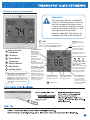
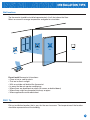
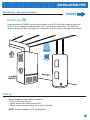
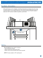
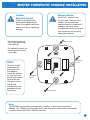
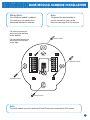
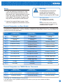
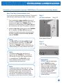
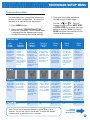
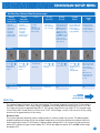
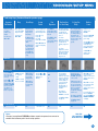
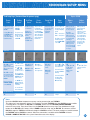
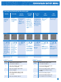
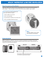
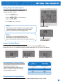
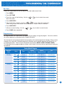
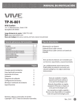
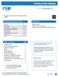
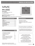
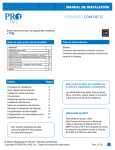
INSTALLATION MANUAL
This manual covers the following models:
• T955WH Master Thermostat
• Base Module
Power Type
Thermostat Applications Guide
Description
Gas or Oil Heat
Yes
Electric Furnace
Yes
Heat Pump (No Aux. or Emergency Heat)
Yes
Heat Pump (with Aux. or Emergency Heat)
Yes
Multi-stage Systems
Yes
Heat Only Systems
Yes
Cool Only Systems
Yes
Dual Fuel Systems
Yes
Millivolt
No
Humidity
Yes
Table of Contents
Page
Thermostat Quick Reference
Installation Tips
Subbase Installation
Wiring
Establishing Communication
Technician Setup Menu
Mounting & Battery Installation
Setting The Humidity
Programming The Thermostat
Specifications & Contact Info
2
3-5
6-7
8
9
10-14
15
16
17-20
21
Una versión española de este
manual puede ser descargada
en www.pro1iaq.com
® U.S. Registered Trademark. Patents pending.
Copyright © 2010 PRO1 IAQ, Inc. All rights reserved.
Battery Power*
Hardwire (Common Wire)
Hardwire (Common Wire) with Battery Backup
* If using remote sensors the thermostat
must be hardwired.
A trained, experienced technician
must install this product.
Carefully read these instructions. You
could damage this product or cause a
hazardous condition if you fail to follow
these instructions.
Need Help?
For assistance with this product please
visit http://www.pro1iaq.com or call Pro1
Customer Care toll-free at 888-Pro1iaq
(776-1427) during normal business hours
(Mon-Fri 9 AM - 6 PM Eastern)
Rev. 1011
1
Getting to know your thermostat
2
Important:
The low battery indicator is displayed
when the AA battery power is low. If the
user fails to replace the battery within
21 days, the thermostat display will only
show the low battery indicator as a final
warning before the thermostat
becomes inoperable. The batteries are
located on the back of the thermostat.
5
1
4
7
6
3
1
LCD
Days of the week and time. Flashes ambient
humidity level. May also flash outside temperature
when used with R250W. OUTDOOR will show.
2
Glow in the Dark
Light Button
3
Fan Button
Programmable Time
Period Icons:
This thermostat has
4 programmable
time periods per day.
4
System Button
Temperature:
Indicates the current
system temperature.
5
Temperature
Setpoint Buttons
Humidity:
Shows the humidity target
setpoint settings and keys.
6
Menu Button
7
Humidity Button
NOTE ABOUT THE LIGHT BUTTON:
This button is used to light up the
display, but it is also used to set up
communication with the base module.
DO NOT hold the light button down for
more then 10 seconds, unless you are
performing the initial communication
setup steps.
Clean Display:
Pressing CLEAN DISPLAY
will allow 30 seconds to clean
the display. The keys will be
inoperable during this time.
CLEAN will appear if your
contractor has programmed a
filter change reminder. Press
CLEAN when filter has been
replaced to reset the filter
change reminder timer.
REMOTE indicates a
remote has control of the
system.
HOLD is displayed when
thermostat program is
permanently overridden.
Displays the user selectable
setpoint temperature.
System operation indicators:
The COOL, HEAT or FAN icon
will display when the COOL,
HEAT or FAN is on.
NOTE: The compressor delay
feature is active if these icons
are flashing. The compressor
will not turn on until the 5
minute delay has elapsed.
COOL
Low Battery Indicator:
Replace batteries when
this indicator is shown.
Wireless Icon
Program Menu Options:
Shows different options
during programming.
HEAT
FAN
System Information:
Shows which zone or
zones are controlling
your system. Shown
only when one or more
indoor sensors R251W
are connected.
2
INSTALLATION TIPS
Wall locations
The thermostat should be installed approximately 4 to 5 feet above the floor.
Select an area with average temperature and good air circulation.
NO
NO
YES
NO
Do not install thermostat in locations:
• Close to hot or cold air ducts
• That are in direct sunlight
• With an outside wall behind the thermostat
• In areas that do not require conditioning
• Where there are dead spots or drafts (in corners or behind doors)
• Where there might be concealed chimneys or pipes
• Where appliances could radiate heat
PRO1 Tip
Pick an installation location that is easy for the user to access. The temperature of the location
should be representative of the building.
3
INSTALLATION TIPS
Base Module - Basement Installation
ATTIC INSTALLATION
ON THE NEXT PAGE
Wireless Range
Range between the T955WH and the base module is up to 100 feet with no obstructions and
up to 50 feet in standard residential metal, brick, and concrete construction. To extend the
range try placing the base unit higher if in a basement or further away from large metal objects.
BETTER
NO
GOOD
PRO1 Tip
Do not install the base module in locations:
• That are behind a chimney
• Where temperature could exceed 150ºF
• Where rain or snow or extreme hot or cold is possible
NOTE: The base module is NOT weatherproof.
4
INSTALLATION TIPS
Base Module - Attic Installation
When performing an attic installation, instead of placing the base module in the attic, locate
the closet nearest to the air conditioning unit. Then mount the base module high on the wall
inside the closet or on the ceiling of the closet. This location will insure the base module is
below the 150ºF maximum ambient temperature specification.
Attic
Living Space Closet
PRO1 Tip
Do not install the base module in locations:
• That are behind a chimney
• Where temperature could exceed 150ºF
• Where rain or snow or extreme hot or cold is possible
NOTE: The base module is NOT weatherproof.
5
MASTER THERMOSTAT SUBBASE INSTALLATION
Caution:
Electrical Hazard
Mercury Notice:
All of Pro1’s products are
mercury free. However, if the
product you are replacing
contains mercury, dispose of it
properly. Your local waste
management authority can give
you instructions on recycling
and proper disposal.
Failure to disconnect the
power before beginning to
install this product can cause
electrical shock or equipment
damage.
For vertical mount put
one screw top and one
screw bottom.
Vertical mount
For horizontal mount put
one screw left and one
screw right.
UP
C
NOTE:
To insure a solid
fit between the
thermostat and
the subbase,
mount the subbase
on a flat wall with
the drywall anchors
flush to the wall.
Using the screws
and drywall
anchors that were
provided with the
thermostat.
Horizontal
mount
R
Horizontal
mount
Vertical mount
Note:
The T955WH can be battery powered only if used as a stand-alone thermostat
solution. The T955WH must be hardwired (C and R terminals connected to 24V power)
if remote sensors (R251W or R250W) are used.
6
BASE MODULE SUBBASE INSTALLATION
Wiring Note:
Note:
Wire the base module’s subbase
the same way you would wire a
hardwired thermostat subbase.
To connect the base module to
master thermostat, refer to the
directions on page 9 of this manual.
For vertical mount put
one screw top and one
screw bottom.
Vertical mount
For horizontal mount put
one screw left and one
screw right.
UP
C
Rh
O
Rc
B
G
W1/E
Y1
W2
Y2
H
D
Horizontal mount
Horizontal mount
Vertical mount
Note:
The base module must be hardwired (C and R terminals connected to 24V power).
7
WIRING
Wiring
Warning:
All components of the control
system and the thermostat
installation must conform to
Class II circuits per the NEC Code.
1. If you are replacing a thermostat, make
note of the terminal connections on the
thermostat that is being replaced. In some
cases the wiring connections will not be
color coded. For example, the green wire
may not be connected to the G terminal.
Wire specifications
Use shielded or non-shielded
18 - 22 gauge thermostat wire.
2. Loosen the terminal block screws. Insert
wires then retighten terminal block screws.
Note:
In many heat pump systems with no
emergency heat relay a jumper can be
installed between E and W2.
Terminal Designations on Base Module
This thermostat is shipped from the factory to operate a conventional heating and cooling system. This thermostat will
also operate a heat pump system. See the “heat pump” configuration step on page 12 of this manual to configure the
thermostat for heat pump applications.
Terminal
2 Heat 2 Cool
Conventional System
2 Heat 2 Cool
Heat Pump System
3 Heat 2 Cool
Heat Pump System
RH
Transformer power
(cooling)
Transformer power
(heating)
Transformer power
(cooling)
Transformer power
(heating)
Transformer power
(cooling)
Transformer power
(heating)
C
Transformer common
Transformer common
Transformer common
B
Energized in heating
Heat pump changeover valve
energized in heating
Heat pump changeover valve
energized in heating
O
Energized in cooling
Heat pump changeover valve
energized in cooling
Heat pump changeover valve
energized in cooling
G
Fan relay
Fan relay
Fan relay
W/E
First stage of heat
Emergency heat relay
Emergency heat relay
Y
First stage of cool
First stage of heat & cool
First stage of heat & cool
Y2
Second stage of cool
Second stage of cool
W2
Second stage of heat
Auxiliary heat relay,
second stage of heat
Second stage of cool
& second stage of heat
Auxiliary heat relay,
third stage of heat
H
Humidify
Humidify
Humidify
D
Dehumidify
Dehumidify
Dehumidify
RC
5
Terminal Designations on T955WH Master Thermostat
Terminal
2 Heat 2 Cool
Conventional System
2 Heat 2 Cool
Heat Pump System
3 Heat 2 Cool
Heat Pump System
R
24 VAC Transformer power
24 VAC Transformer power
24 VAC Transformer power
C
Transformer common
Transformer common
Transformer common
Powering the T955WH Master Thermostat
If you add remote sensors (R250W or R251W) to this wireless system you must hardwire theT955W
master thermostat.
8
ESTABLISHING COMMUNICATION
Establishing Communication between T955W Master Thermostat and the Base Module
Easy, Two Step Communication Link
To set up the initial link between the Master Thermostat
and the base module please follow the steps below:
Step 1.
LED Relay Indicators
Blue LED
1. Press and hold the base module button for 3
seconds. The Blue LED will flash when ready to
receive initial signal from T955WH. (Base
module must be powered by 24V. Blue LED will
be continuously on when 24V power is present.)
2. Hold the Light key (shown here) of the T955WH
for 10 seconds, the Blue LED on the base
module will stop flashing after communication
has been established between base module
and the T955WH.
Note:
The Blue LED on the base module will be
on when power is present. The Blue LED
will flash 3 times every time it receives a
signal from T955WH. When a relay is on the
corresponding LED relay indicator will be on.
Base Module Button
Step 2.
Light key
Note:
If the base module does not receive a
signal from the T955WH for 15 minutes it
will turn off all relays until communication
is reestablished. The Blue LED on the
base module will also turn off to show
communication has been lost.
Note:
If communication has been lost for 1 hour
and if freeze protection is enabled, heat and
emergency heat relays will be turned on.
The heat and emergency heat relays will
turn on for 10 minutes every hour if there
has been a call for heat in the last 24 hours.
Important:
DO NOT hold the light button
on the T955WH for more
than 10 seconds after Step 2
above has been completed.
Holding the light button down
will break the communication
link and the base module
button will need to be
pressed again to reestablish
communication.
9
TECHNICIAN SETUP MENU
Technician Setup Menu
This thermostat has a technician setup menu
for easy installer configuration. To set up the
thermostat for your particular application:
1. Press MENU button
2. Press and hold TECHNICIAN SETUP
button for 3 seconds. This 3 second delay
is designed so that homeowners do not
accidentally access the installer settings.
3. Configure the installer options as
desired using the table below.
Use the
or
keys to
change settings and the NEXT STEP
or PREV STEP key to move from one
option to another. Note: Only press
DONE key when you want to exit the
Technician Setup options.
Tech Setup Steps
Filter
Change
Reminder
Room
Temperature
Calibration
Minimum
Compressor
On Time
Compressor
Short Cycle
Delay
The compressor short
cycle delay protects
the compressor from
“short cycling”. This
feature will not allow
the compressor to be
turned on for 5
minutes after it was
last turned off.
This feature will
flash FILT in the
display after the
elapsed run time
to remind the
user to change the
filter. A setting of
OFF will disable
this feature.
This feature allows
the installer to
change the
calibration of the
room temperature
display. For
example, if the
thermostat reads 70°
and you would like it
to read 72° then
select +2.
This feature allows the
installer to select the
minimum run time for
the compressor.
For example, a setting
of 4 will force the
compressor to run for
at least 4 minutes
every time the
compressor turns on,
regardless of the room
temperature.
You can adjust
the filter change
reminder from
OFF to 2000
hours of runtime
in 50 hour
increments.
You can adjust the
room temperature
display to ready -4°F
to +4°F above or
below the factory
calibrated reading.
You can select the
minimum compressor
run time from “off”,
“3”, “4”, or “5”
minutes. If 3, 4, or 5
is selected, the
compressor will run
for at least the
selected time before
turning off.
OFF
0 ºF
OFF
Selecting ON will not
allow the compressor
to be turned on for 5
minutes after the last
time the compressor
was on. Select OFF
to remove this delay.
ON
Cooling
Swing
Heating
Swing
The swing setting,
often called “cycle
rate”, “differential”
or “anticipation” is
adjustable. A smaller
swing setting will
cause more frequent
cycles and a larger
swing setting will
cause fewer cycles.
The swing setting,
often called “cycle
rate”, “differential”
or “anticipation” is
adjustable. A
smaller swing setting
will cause more
frequent cycles and a
larger swing setting
will cause fewer
cycles.
The cooling swing
setting is adjustable
from ±0.2°F to
±2°F. For Example:
A swing setting of
0.5°F will turn the
cooling on at
approximately 0.5°F
above the setpoint
and turn the cooling
off at approximately
0.5°F below the
setpoint.
The heating swing
setting is adjustable
from ±0.2°F to
±2°F. For Example:
A swing setting of
0.5°F will turn the
heating on at
approximately 0.5°F
below the setpoint
and turn the heating
off at approximately
0.5°F above the
setpoint.
0.5 ºF
Note: To lock the keypad hold down the
and
keys for 3
seconds. You will see a lock in the display. To unlock the keypad
hold down the
and
keys for 3 seconds.
0.4 ºF
Keypad
Lockout
Keypad lockout
allows you to
configure the
thermostat so that
none or some of
the keys do not
function.
Pick PA or FU
PA = partial keypad
lockout, which locks
all the keys except the
or
keys.
FU = Full keypad
lockout, which locks
out all the keys.
Note: Keypad lockout
instructions are below.
PA
TECH SETUP
STEPS CONTINUED
ON THE NEXT PAGE
10
TECHNICIAN SETUP MENU
Tech Setup Steps (Continued from the previous page)
Heating
Temperature
Setpoint Limit
Cooling
Temperature
Setpoint Limit
ºF or ºC
12 or 24
Hour Clock
Morning
Recovery
Program
Options
Display
Light
This feature
allows you to set a
maximum heat
setpoint value.
The setpoint
temperature
cannot be raised
above this value.
This feature
allows you to set a
minimum cool
setpoint value.
The setpoint
temperature
cannot be lowered
below this value.
Select F for
Fahrenheit
temperature read
out or select C for
Celsius read out
You can select
either a 12 or 24
hour clock setting.
This feature turns your
system on before the
WAKE programming
time to ensure the
enviroment is at the
WAKE setpoint when
the WAKE time period
begins. This recovery
changes over time
based on the previous
day’s experience.
You can configure this
thermostat to have a
7 day program, a
5+1+1 program or
nonprogrammable.
The display light can
be configured to come
on when any key is
pressed or only when
the light key is pressed.
ºF for Fahrenheit
Use the
or
key to select 12 or 24
hour clock.
Use the
or
key to turn on or off.
Use the
or
key to select 7d for 7
day, 5d for 5+1+1,
or 0d for
nonprogammable.
OFF configures display
light to come on only
with the light key,
which will save battery
power.
LCD Will Show
Adjustment Options
Use the
or
key to select the
maximum heat
setpoint.
Use the
or
key to select the
minmum cool
setpoint.
ºC for Celsius
ON configures the
display light to come
on when any key is
pressed.
Factory Default Settings
90 ºF
PRO1 Tip
44 ºF
ºF
12 Hour Clock
ON
5d
ON
TECH SETUP
STEPS CONTINUED
ON THE NEXT PAGE
The second stage will turn on at 2x the swing setting. The second stage will turn off when 1x the swing is
reached. For example, if the swing setting is .8 degrees for heating and the thermostat is set at 70ºF, the
first stage will turn on at approximately 69.2ºF. The second stage will turn on at 68.4ºF. The second stage
will turn off at 69.2ºF and the first will turn off at 70.8ºF. If third stage is used, it will turn on at 3x the swing
and turn off at approximately 2x the swing.
Balance Point:
The system operates differently when a balance point is used on a dual fuel system. The balance point
outdoor temperature setting will be the outdoor temperature at which the thermostat chooses either the
heat pump or gas furnace. For Example: A balance point setting of 30ºF will turn on only the heat pump
above 30ºF and only the gas furnace below 30ºF. Y1 will be stage one above 30ºF and W2 will be stage
one below 30ºF.
11
TECHNICIAN SETUP MENU
Tech Setup Steps (Continued from the previous page)
Contractor
Call Number
Allows you to put
your phone
number in the
display.
You can choose
ON or OFF
Beep
When any key is
pressed an audible
beep will sound.
You can choose
ON or OFF
Fan
Operation
Gas Auxiliary
for Heat Pump
Cooling Fan
Delay
Outdoor
Sensor
You can configure the Select GAS for
system switch for the systems that control
particular application: the fan during a call
for heat.
Heat - Off - Cool,
Heat - Off,
1. EM.Heat will
Select ELEC to have
show as an option Cool - Off,
the thermostat
Heat - Off - Cool-Auto control the fan during
in the system
switch.
a call for heat.
Note: EM. Heat will
show if in heat pump
2. Y will be first
mode.
stage of heat &
cool, W/E will be
emergency heat
relay & W2 will
be auxiliary heat
relay.
This option will turn
the heat pump off 45
seconds after the
auxiliary heat relay
turns on.
The cooling fan delay
setting will delay the
fan from coming on in
cool mode and keep
running after the
compressor shuts off
for a short time to save
energy in some
systems.
Enables the use of an
outdoor sensor
R250W.
OFF configures
the thermostat
for non heat
pump systems.
For heat pump
systems that are
“dual fuel” (use a gas
furnace for auxiliary
stage heat) you can
turn this feature on
to turn off the heat
pump when the
auxiliary stage of
heating has been
called for.
Heat Pump
System
Switch
When turned on
the thermostat
will operate a
heat pump.
For 2 heat
applications, the first
stage will turn off 45
seconds after the
auxiliary stage turns
on.
For 3 heat
applications, the first
and second stage will
turn off 45 seconds
after the auxiliary
stage turns on.
Connecting a R250W
allows for a balance
point setting.
Selecting YES requires
the T955WH master
thermostat to be
powered with 24V on
C and R terminals.
See R250W user
guide for more
information.
LCD Will Show
Adjustment Options
If selected ON, you
will see the input
screen after pressing
next step.
If ON is selected
the beep will
sound.
Use the
or
key to select the
desired number and
the FAN or SYSTEM
key to move from
one character to
another. See note
below on operation.
If OFF is selected,
there is no sound.
Use the
or
key until the desired
application is
flashing.
GAS
or
ELEC
ON configures
the thermostat
for heat pump
systems.
This feature is
disabled when a
R250W is connected.
See Balance Point
on page 13.
You can select the
Cooling Fan Delay
from OFF, 15, 30, 60
or 90 seconds.
If 15, 30, 60 or 90 is
selected the fan will not
turn on for that many
seconds when there is a
call for cool and will
run for that many
seconds after satisfying
a call for cool.
This feature is disabled
when a R250W is used.
See Balance Point
on page 13.
When NO is selected
the thermostat is
unable to connect to an
outdoor remote sensor
R250W.
When YES is selected
the thermostat is able
to connect to an
outdoor remote sensor
R250W.
Press and hold connect
button on R250W
until the T955WH says
FOUND OUTDOOR
on display.
Factory Default Settings
OFF
ON
OFF
Heat - Off - Cool
GAS
Note:
Connect an optional R250W outdoor remote temperature sensor to
enable the balance point tech setup option.
OFF
OFF
NO
TECH SETUP
STEPS CONTINUED
ON THE NEXT PAGE
12
TECHNICIAN SETUP MENU
Tech Setup Steps (Continued from the previous page)
Remote
Sensor
Requires R250W
Energy Star®
Logo
Stages
of Heat
Balance
Point
Balance
Run Time
Disable the sensor Turns on the heat
for 10 minutes
on the master.
each hour if unable
to communicate
At least one
R251W indoor
with the T955WH
remote sensor
master thermostat
must be
if there has been a
connected to
call for heat in the
disable the local
last 24 hours.
T955WH sensor.
Shows the Energy
Star logo when the
program meets
Energy Star
guidelines.
You can configure the
thermostat to operate
a 3 stage heat pump
system.
Balance point can
eliminate the need
for a fossil fuel kit.
Balance point run
time will allow the
W2 auxiliary
terminal to energize
even if outdoor
temperature is above
the selected balance
point temperature. If
enabled, auxiliary
will energize for the
current cycle after
the balance point
run time has
expired.
The number shown
represents the zone.
YES enables local
T955WH sensor
YES enables
freeze protection
Use
or
to select the zone
you wish to connect.
NO disables local
T955WH sensor
NO disables
freeze protection
YES enables
Energy Star
feature
Use the
or
key to change between
2 heat and 3 heat.
NO disables
Energy Star
feature
2 heat will use Y1 as
first stage and W2 as
auxiliary.
Finding
Sensor
Enables the use of up
to four indoor sensors
R251W.
This step connect
R251W to
T955WH.
Selecting YES requires
the T955WH master
thermostat to be
powered with 24V on
C and R terminals.
The previous step
Remote Sensor
must be set to YES
in order to connect
an R251W.
Local Temp
Sensor
Freeze
Protection
An outdoor
temperature above
balance point will
cause the thermostat
This feature only shows to only allow the Y
if Technician Setup
terminal(s) to
Step for HEAT PUMP energize. An outdoor
is set to ON.
temperature below
balance point will
cause the thermostat
to only allow the W2
to energize.
2H 2C = 2 heat, 2 cool
3H 2C = 3 heat, 2 cool
LCD Will Show
Adjustment Options
When NO is selected
the thermostat is
unable to connect to an
indoor remote sensor
R251W.
When YES is selected
the thermostat is able
to connect to up to four
indoor remote sensors
R251W.
The zone setting on
the T955WH and the
R251W must be the
same to connect.
Go to the next step
FINDING SENSOR to
connect R251W.
See R251W user
guide for detailed
R251W connection
information.
3 heat will use Y1 as
first stage, Y2 as
second stage and
W2 as auxiliary.
YES
10, 20, 30, 35, 40,
45, 50 outdoor
temperature
balance point
setting.
YES
15, 30, 45, 60, 75, 90
continuous run time
minutes.
NO
NO
See note below for
more information.
Factory Default Settings
NO
1
YES
NO
NO
2 Stages
NO
NO
Note:
Up to four R251W indoor temperature sensors can be connected to one T955WH.
This allows for 5 sensing points (zones). For Example: The local (T955WH) plus four R251W sensors enables
5 sensing points. To connect an R251W to a T955WH, Select 1 on the T955WH FINDING SENSOR
technician setup step. Then select Zone 1 on the R251W technician setup step. Then hold down the light
button on the R251W until it beeps, while in ZONE technician setup step on R251W. To connect a second
R251W change the T955W to read 2 and change the R251W to zone 2. The zone setting must match between
the T955WH and the R251W to connect. When the connection is established the T955WH will show
FOUND + NAME OF R251W in the system information area of the display.
13
TECHNICIAN SETUP MENU
Tech Setup Steps (Continued from the previous page)
Humidify
Dehumidify
Humidity
Calibration
Dehumidify
with AC
Over Cool
Limit
This feature adds
humidity when
System key is
in Heat.
This feature
removes humidity
when System key
is in Cool.
This feature allows
the installer to
change the
callibration of the
ambient humidity
displayed.
This feature forces
the A/C to run
longer to remove
humidity when
needed. The A/C
will “over cool” the
room a few degrees
until the humidity
reaches the desired
setpoint.
The amount of over
cooling allowed when
using A/C to remove
humidity. This screen
is only shown when
ON is selected in the
“Dehumidify with AC”
tech setup step.
Options for how the
Hum terminal
energizes.
Option for how DHM
terminal energizes.
Use the
or
key to turn on or off.
Use the
or
key to turn on or off.
If ON is selected the
humidity will be
displayed on the main
screen and DHM
terminal will energize
when humidity
setpoint is below
ambient humidity in
Cool mode.
Use the
or
key to select YES or
NO.
Use the
or
key to select the
If ON is selected the
humidity will be
displayed on the main
screen and Hum
terminal will energize
when humidity
setpoint is above
ambient humidity in
Heat mode.
Use the
or
key to adjust the
calibration +/– 3.
Use the
or
key to select one of the
four options.
Use the
or
key to select one of the
four options.
Options are:
2, 3, 4, 5
View the
HUM Terminal chart
below for an explanation
of these options.
View the
DHM Terminal chart
below for an explanation
of these options.
3
1
HUM
Terminal
DHM
Terminal
LCD Will Show
Adjustment Options
If selected YES allows
over cooling to be used
to control humidity in
Cool mode. If NO is
selected the system will
not use over cooling.
maximum number of
degrees of over cool.
Factory Default Settings
OFF
OFF
0
HUM Terminal
OPTIONS
HUM terminal energizes when
the ambient humidity is...
NO
1
DHM Terminal
OPTIONS
DHM terminal energizes when
the ambient humidity is...
1
below the humidity setpoint and
heat or fan is energized.
1
above the humidity setpoint and
cool or fan is energized.
2
below the humidity setpoint and
heat is energized.
2
3
below the humidity setpoint. It will
also energize the fan during a call
for humidity.
above the humidity setpoint. It will also
energize the fan during a call for
humidity.
3
above the humidity setpoint.
4
below the humidity setpoint.
4
above the humidity setpoint and
the compressor is not running.
14
MOUNT THERMOSTAT & BATTERY INSTALLATION
Mount Thermostat and Base Module
Align the 4 tabs on the subbase with corresponding slots on the back of the thermostat or
base module. Then push gently until the thermostat or base module snaps in place.
Note: To insure a solid fit between the
thermostat and the subbase:
1. Mount subbase to a flat wall
2. Use screws provided
3. Drywall anchors should be flush with the wall
4. Wires should be pushed into the wall
Note:
The base module can be wired
from the back or the bottom.
Battery installation is optional if there are no remotes connected to the Master Thermostat
(C terminal connected). If you connect an outdoor remote and/or indoor remote sensors it is
required the thermostat be hardwired.
C
R
On the back of the thermostat insert
2 AA Alkaline batteries (included).
15
SETTING THE HUMIDITY
Setting Target Humidity Setpoint
Follow the steps below to change your
target humidity setpoint.
Press the HUMIDITY key
Use the
or
key to select the
target humidity setpoint.
Press DONE when completed
Note:
The target humidity setpoint is not programmable.
Unlike temperature, humidity does not change
quickly and should not be programmed.
HUMIDITY KEY
Note:
Humidity is only energized during heat.
Dehumidify is only energized during cool.
Heat and Cool each have their own target setpoints.
TARGET HUMIDITY
SETPOINT KEYS
Ambient Humidity Display
Ambient humidity will flash opposite the day and time, if the optional R250W outdoor
temperature sensor is installed the ambient outdoor temperature will also cycle in the display.
AMBIENT HUMIDITY
DAY & TIME
Recommended Heating Settings:
Increasing Humidity
The table on the right shows
recommended indoor humidity levels in
relation to outdoor temperatures during
heating (adding humidity).
OUTDOOR TEMPERATURE
Outside
Temperature (0°F)
Recommended
Relative Humidity
+20º and above
+10º
0º
35% to 40%
30%
25%
-10º
-20º
20%
15%
Recommended Cooling Settings:
Consult your professional HVAC technician for recommended settings for your climate.
16
PROGRAMMING THE THERMOSTAT
Set Time
Follow the steps below to set the day of the week and current time:
1. Press MENU
2. Press SET TIME
3. Day of the week will be flashing. Use the
day of the week.
or
key to select the current
4. Press NEXT STEP
5. The current hour is flashing. Use the
or
key to select the current hour.
When using 12-hour time, make sure the correct a.m. or p.m. choice is selected.
6. Press NEXT STEP
7. Minutes are now flashing. Use the
or
key to select current minutes.
8. Press DONE when completed
Programming
All programmable Pro1 thermostats are shipped with an energy saving pre-program. You can customize
this default program by following the Set Program Schedule.
Your thermostat can be programmed to have each day of the week programmed uniquely (7days), all the
weekdays the same with a separate program for Saturday and a separate program for Sunday (5+1+1),
or nonprogrammable. There are four time periods for each day (WAKE, LEAVE, RETURN, SLEEP).
This thermostat has a programmable fan feature, which allows you to run the fan continuously during any
time period.
Factory Default Program
Day of the
Week
Weekday
Saturday
Sunday
Events
Time
Setpoint
Setpoint
Temperature (Heat) Temperature (Cool)
Zone
(If R251W is connected)
Wake
6 a.m.
70° F (21° C)
75° F (24° C)
System Average
Leave
8 a.m.
62° F (17° C)
83° F (28° C)
System Average
Return
6 p.m.
70° F (21° C)
75° F (24° C)
System Average
Sleep
10 p.m.
62° F (17° C)
78° F (26° C)
System Average
Wake
8 a.m.
70° F (21° C)
75° F (24° C)
System Average
Leave
10 a.m.
62° F (17° C)
83° F (28° C)
System Average
Return
6 p.m.
70° F (21° C)
75° F (24° C)
System Average
Sleep
11 p.m.
62° F (17° C)
78° F (26° C)
System Average
Wake
8 a.m.
70° F (21° C)
75° F (24° C)
System Average
Leave
10 a.m.
62° F (17° C)
83° F (28° C)
System Average
Return
6 p.m.
70° F (21° C)
75° F (24° C)
System Average
Sleep
11 p.m.
62° F (17° C)
78° F (26° C)
System Average
17
PROGRAMMING THE THERMOSTAT
You can use the table below to plan your customized program schedule if using 5+1+1.
Factory Default Program
Day of the
Week
Weekday
Events
Time
Setpoint
Setpoint
Temperature (Heat) Temperature (Cool)
Zone
(If R251W is connected)
Wake
Leave
Return
Sleep
Saturday
Wake
Leave
Return
Sleep
Sunday
Wake
Leave
Return
Sleep
18
PROGRAMMING THE THERMOSTAT
Set 5+1+1 Program Schedule
To customize your 5+1+1 program schedule, follow these steps
Weekday:
1. Select HEAT or COOL using the SYSTEM key.
Note: You have to program heat and cool each separately.
2. Press MENU
3. Press SET SCHED. Note: Monday-Friday is displayed and the WAKE icon is shown. You are now
programming the WAKE time period for the weekday setting.
Additional step if R251W indoor remote sensor is connected.
The T955WH master thermostat will either average all sensors (system average) or only
use one sensor for the system ambient temperature (priority). The default setting is
SYSTEM AVERAGE, which means all sensors are averaged to create the system average
ambient temperature reading. The NEXT ZONE key can be pressed to change the priority.
The system information area of the display shows the priority.
For Example: There is an R251W connected and it is named REMOTE 1. If the NEXT
ZONE key is pressed until REMOTE 1 is shown, then the REMOTE 1 ambient temperature
reading will be used exclusively for that time period. All other sensors will be ignored.
4. Time is flashing. Use the
or
key to make your time selection for the weekday WAKE time
period. Note: If you want the fan to run continuously during this time period, select ON with the FAN key.
5. Press NEXT STEP
6. The setpoint temperature is flashing. Use the
weekday WAKE period.
or
key to make your setpoint selection for the
7. Press NEXT STEP
8. Repeat steps 4 through 7 for weekday LEAVE time period, for weekday RETURN time period, and for
weekday SLEEP time period.
Saturday:
9. Repeat steps 4 through 7 for
Saturday WAKE time period, for
Saturday LEAVE time period, for
Saturday RETURN time period, and
for Saturday SLEEP time period.
Sunday:
10. Repeat steps 4 through 7 for
Sunday WAKE time period, for
Sunday LEAVE time period, for
Sunday RETURN time period, and
for Sunday SLEEP time period.
19
PROGRAMMING THE THERMOSTAT
Set 7 Day Program Schedule
To customize your 7 day program schedule, follow these steps:
Monday
1. Select HEAT or COOL using the system key. You have to program heat and cool each separately.
2. Press MENU
3. Press SET SCHED
Note: Monday is displayed and the WAKE icon is shown. You are now programming the WAKE
time period for the Monday setting.
Additional step if R251W indoor remote sensor is connected.
The T955WH master thermostat will either average all sensors (system average) or only
use one sensor for the system ambient temperature (priority). The default setting is
SYSTEM AVERAGE, which means all sensors are averaged to create the system average
ambient temperature reading. The NEXT ZONE key can be pressed to change the priority.
The system information area of the display shows the priority.
For Example: There is an R251W connected and it is named REMOTE 1. If the NEXT
ZONE key is pressed until REMOTE 1 is shown, then the REMOTE 1 ambient temperature
reading will be used exclusively for that time period. All other sensors will be ignored.
4. Time is flashing. Use the
or
key to make your time selection for the Monday WAKE
time period. Note: If you want the fan to run continuously during this time period, select ON with
the FAN key.
5. Press NEXT STEP
6. The setpoint temperature is flashing. Use the
the Monday WAKE period.
or
key to make your setpoint selection for
7. Press NEXT STEP
8. Repeat steps 4 thru 7 for Monday LEAVE time period, for Monday RETURN time period, and for
Monday SLEEP time period.
Tuesday, Wednesday, Thursday, Friday, Saturday, Sunday
Repeat steps 4 thru 7 for the remaining days of the week.
A Note About Auto Changeover:
Auto changeover will switch between heating
and cooling as needed. It is very important to
make sure the cooling setpoint temperature is at
least 3º above the heating setpoint temperature
and that the heating setpoint temperature is at
least 3º below the cooling setpoint temperature.
A Note About Programmable Fan:
The programmable fan feature will
run the fan continuously during any
time period it is programmed to be
on. This is the best way to keep the
air circulated and to eliminate hot
and cold spots in your building.
20
SPECIFICATIONS & CONTACT INFORMATION
Specifications
T955WH Thermostat
The display range of temperature
The control range of temperature
Load rating
Display accuracy
Swing (cycle rate or differential)
Power source
Operating ambient
Operating humidity
Dimensions of thermostat
Frequency
41ºF to 95ºF (5ºC to 35ºC)
44ºF to 90ºF (7ºC to 32ºC)
1 amp per terminal, 1.5 amp maximum all terminals combined
± 1ºF
Heating is adjustable from 0.2ºF to 2.0ºF
Cooling is adjustable from 0.2ºF to 2.0ºF
18 to 30 VAC, NEC Class II, 50/60 Hz for hardwire (common wire)
Battery power from 2 AA Alkaline batteries
32ºF to +105ºF (0º to +41ºC)
90% non-condensing maximum
4.7”W x 4.4”H x 1.1”D
916 MHz
Base Module
Load rating
Power source
Operating ambient
Operating humidity
1 amp per terminal, 1.5 amp maximum all terminals combined
18 to 30 VAC, NEC Class II, 50/60 Hz
32ºF to +150ºF (0º to +65ºC)
90% non-condensing maximum
Pro1 IAQ Inc.
1111 S. Glenstone
Suite 2-100
Springfield, MO 65804
Toll-free: 1-888-Pro1iaq (776-1427)
Toll Number (Outside the USA): 330-821-3600
Web: http://www.pro1iaq.com
Hours of Operation: Monday - Friday 9 AM - 6 PM Eastern
21