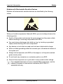
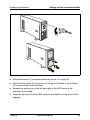
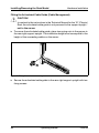
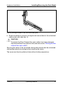
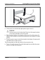
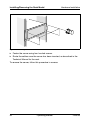
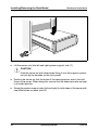
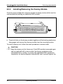
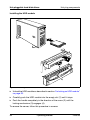
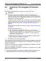
1
PRIMERGY TX200 S3 Server
Operating Manual
Edition December 2006
Comments… Suggestions… Corrections…
The User Documentation Department would like to
know your opinion of this manual. Your feedback helps
us optimize our documentation to suit your individual
needs.
Fax forms for sending us your comments are included in
the back of the manual.
There you will also find the addresses of the relevant
User Documentation Department.
Certified documentation
according to DIN EN ISO 9001:2000
To ensure a consistently high quality standard and
user-friendliness, this documentation was created to
meet the regulations of a quality management system
which complies with the requirements of the standard
DIN EN ISO 9001:2000.
cognitas. Gesellschaft für Technik-Dokumentation mbH
www.cognitas.de
Copyright and Trademarks
Copyright © 2006 Fujitsu Siemens Computers GmbH.
All rights reserved.
Delivery subject to availability; right of technical modifications reserved.
All hardware and software names used are trademarks of their respective manufacturers.
Contents
1
1.1
1.2
1.3
1.4
Introduction . . . . . .
Documentation Overview
Features . . . . . . . . .
Notational Conventions .
Technical data . . . . . .
2
Installation Steps: Overview
3
3.1
3.2
3.3
3.4
3.5
3.6
Important Information . . . . . . .
Safety . . . . . . . . . . . . . . . .
CE Conformity . . . . . . . . . . . .
FCC Class A Compliance Statement
Transporting the Server . . . . . . .
Notes on Installing in the Rack . . .
Environmental Protection . . . . . .
.
.
.
.
.
.
.
.
.
.
.
.
.
.
.
.
.
.
.
.
.
.
.
.
.
.
.
.
.
.
.
.
.
.
.
.
.
.
.
.
.
.
.
.
.
.
.
.
.
.
.
.
.
.
.
.
21
21
28
29
30
30
31
4
4.1
4.2
4.3
4.3.1
4.3.2
4.3.3
4.3.4
4.4
4.5
4.6
Hardware Installation . . . . . . . . . . . . . .
Unpacking the Server . . . . . . . . . . . . . . .
Setting up the floorstand model . . . . . . . . . .
Installing/Removing the Rack Model . . . . . . .
Mounting in the PRIMECENTER/DataCenter Rack
Installation in Classic Rack . . . . . . . . . . . .
Installation in 3rd Party Racks . . . . . . . . . . .
Inserting the server . . . . . . . . . . . . . . . .
Connecting Devices to the Server . . . . . . . . .
Connecting the Server to the Mains . . . . . . . .
Instructions for Connecting/Disconnecting Cables
.
.
.
.
.
.
.
.
.
.
.
.
.
.
.
.
.
.
.
.
.
.
.
.
.
.
.
.
.
.
.
.
.
.
.
.
.
.
.
.
.
.
.
.
.
.
.
.
.
.
.
.
.
.
.
.
.
.
.
.
.
.
.
.
.
.
.
.
.
.
.
.
.
.
.
.
.
33
34
34
37
42
44
49
50
56
58
60
5
5.1
5.2
5.2.1
5.2.2
5.3
5.4
5.4.1
5.4.2
5.5
Starting Up and Operation . . . . . . . .
Locking and Unlocking the Floorstand Model
Controls and Displays . . . . . . . . . . . .
Front of server . . . . . . . . . . . . . . . .
Rear of Server . . . . . . . . . . . . . . . .
Switching the Server On and Off . . . . . .
Configuring the Server . . . . . . . . . . .
Configuration with ServerStart . . . . . . .
Configuration without ServerStart . . . . . .
Cleaning the Server . . . . . . . . . . . . .
.
.
.
.
.
.
.
.
.
.
.
.
.
.
.
.
.
.
.
.
.
.
.
.
.
.
.
.
.
.
.
.
.
.
.
.
.
.
.
.
.
.
.
.
.
.
.
.
.
.
.
.
.
.
.
.
.
.
.
.
.
.
.
.
.
.
.
.
.
.
61
61
63
63
67
70
72
72
74
75
6
6.1
Property and Data Protection . . . . . . . . . . . . . . . . .
BIOS Setup Security Functions . . . . . . . . . . . . . . . . .
77
77
TX200 S3
.
.
.
.
.
.
.
.
.
.
.
.
.
.
.
.
.
.
.
.
.
.
.
.
.
.
.
.
.
.
.
.
.
.
.
.
.
.
.
.
.
.
.
.
.
.
.
.
.
.
.
.
.
.
.
.
.
.
.
.
.
.
.
.
.
.
.
.
.
.
.
.
.
.
.
.
.
.
.
.
.
.
.
.
.
.
.
.
.
.
.
.
.
.
.
. . 5
. . 5
. . 7
. 15
. 16
. . . . . . . . . . . . . . . . .
Operating Manual
.
.
.
.
.
.
.
.
.
.
.
.
.
.
.
.
.
.
.
.
.
.
.
.
.
.
.
.
.
.
.
.
.
.
.
.
.
.
.
.
.
.
.
.
.
.
.
.
.
.
.
.
.
.
.
.
.
.
.
.
.
.
.
.
.
.
.
.
.
.
.
.
19
Contents
7
7.1
7.2
7.3
7.4
7.5
7.6
7.7
7.8
7.9
7.10
7.11
7.12
Troubleshooting and Tips . . . . . . . . . . . .
Power On Indicator Remains Unlit . . . . . . . .
Server Switches Itself Off . . . . . . . . . . . . .
Screen Remains Blank . . . . . . . . . . . . . .
Flickering Stripes on Monitor Screen . . . . . . .
No Screen Display or Display Drifts . . . . . . . .
No Mouse Pointer Displayed on Screen . . . . . .
Unable to Read From / Write To Floppy Disk . . .
Incorrect Date and Time . . . . . . . . . . . . . .
System Will Not Boot . . . . . . . . . . . . . . .
Drives Reported as "Dead" When Starting System
Added Drive Reported as Defective . . . . . . . .
Error Message on Screen . . . . . . . . . . . . .
.
.
.
.
.
.
.
.
.
.
.
.
.
.
.
.
.
.
.
.
.
.
.
.
.
.
.
.
.
.
.
.
.
.
.
.
.
.
.
.
.
.
.
.
.
.
.
.
.
.
.
.
.
.
.
.
.
.
.
.
.
.
.
.
.
.
.
.
.
.
.
.
.
.
.
.
.
.
.
.
.
.
.
.
.
.
.
.
.
.
.
79
79
80
80
81
81
81
82
82
82
83
83
83
8
8.1
8.1.1
8.2
8.2.1
8.2.2
8.2.3
8.3
8.4
Hot plug components . . . . . . . . . . . .
Hot-plug power supply units . . . . . . . . . .
Replacing Hot Pluggable Power Supply Units .
Hot-pluggable hard disk drives . . . . . . . .
Handling Hard Disk Drives/HDD Modules . . .
Installing/Removing the Dummy Module . . .
Installing/Removing the HDD Module . . . . .
Replacing a Hot-pluggable CPU/System Fan .
Opening/Closing the Housing . . . . . . . . .
.
.
.
.
.
.
.
.
.
.
.
.
.
.
.
.
.
.
.
.
.
.
.
.
.
.
.
.
.
.
.
.
.
.
.
.
.
.
.
.
.
.
.
.
.
.
.
.
.
.
.
.
.
.
.
.
.
.
.
.
.
.
.
85
85
86
87
89
90
91
96
99
.
.
.
.
.
.
.
.
.
.
.
.
.
.
.
.
.
.
Abbreviations . . . . . . . . . . . . . . . . . . . . . . . . . . . . . . . 101
Literature . . . . . . . . . . . . . . . . . . . . . . . . . . . . . . . . . 107
Index . . . . . . . . . . . . . . . . . . . . . . . . . . . . . . . . . . . . 111
Operating Manual
TX200 S3
1
Introduction
The PRIMERGY TX200 S3 server is an Intel-based server for mid-size and
large companies. The server is suitable for use as a file server and also as an
application, information or Internet server. It is available as a floorstand or rack
model. The floorstand model can be converted to a rack model using an optional
conversion kit.
Thanks to its highly developed hardware and software components, the
PRIMERGY TX200 S3 server offers a high level of data security and availability.
These components include hot-plug hard disk drive modules and power supply
units, optional redundant system fans, the Server Management ServerView Suite,
Prefailure Detection and Analysing (PDA) und Automatic Server Reconfiguration and Restart (ASR&R).
Security functions in the BIOS Setup and on the system board protect the data
on the server against manipulation. Additional security is provided by the
intrusion detection and the lockable drive cover on the floorstand model and the
lockable rack door on the rack model.
The rack model occupies 4 height units in the rack.
1.1
Documentation Overview
I PRIMERGY manuals are available in PDF format on the ServerBooks
DVD. The ServerBooks DVD is part of the ServerStart Suite supplied with
every server system.
The PDF files for the manuals can also be downloaded free of charge
from the Internet. The overview page showing the online documentation
available in the Internet can be found via the URL: http://manuals.fujitsusiemens.com (click industry standard servers).
TX200 S3
Operating Manual
5
Documentation Overview
Introduction
Concept and target group of this manual
This operating manual describes how to install, set up and operate your server.
This manual is intended for those responsible for installing the hardware and
ensuring that the system runs smoothly. The manual contains all the information
required to install and operate your PRIMERGY TX200 S3.
It is assumed that users have some knowledge of hardware and data transmission, and a basic familiarity with the operating system that is being used. You
should also have a good working knowledge of the English language.
Additional server documentation
The PRIMERGY TX200 S3 documentation consists of the following additional
manuals:
– “Safety notes and other important information” manual (print version
delivered together with the system, PDF file available on the ServerBooks
DVD)
– “Warranty” manual (print version delivered together with the system, PDF file
available on the ServerBooks DVD)
– Technical Manual for the D2109 system board (PDF file available on the
ServerBooks DVD)
– “BIOS Setup” (PDF file available on the ServerBooks DVD)
– “PRIMERGY ServerView Suite - ServerStart” (PDF file available on the
ServerBooks DVD)
– “PRIMERGY TX200 S3 Options Guide” (PDF file available on the
ServerBooks DVD)
– “Global Array Manager Client Software User’s Guide” (PDF file available on
the ServerBooks DVD)
– “Integrated Mirroring User’s Guide” (PDF file available on the ServerBooks
DVD)
– “MegaRAID 320-0X Zero-channel PCI-X RAID Storage Adapter User’s
Guide” (PDF file available on the ServerBooks DVD)
– “MegaRAID Configuration Software User’s Guide” (PDF file available on the
ServerBooks DVD)
6
Operating Manual
TX200 S3
Introduction
Features
I If you need a replacement copy of the ServerBooks DVD send the details
of your server to the following e-mail address:
[email protected]
Further sources of information:
–
–
–
–
–
–
–
Technical manual for the corresponding rack
Manual for the monitor
Manual for ServerView server management
Manual for the remote testing and diagnostic system RemoteView
Documentation for the boards and drives
Operating system documentation
Information files in your operating system
(see also “Literature” on page 107).
1.2
Features
System board
The features of the system board (D2109) are described in the technical manual
for the system board in relation to the hardware and in the BIOS setup manual
for the firmware (see “Literature” on page 107).
Hard disk drives
The server is available in three basic variants: with SCSI, SATA, or SAS hard
disk drives.
Basic variant with SCSI hard disk drive
The server has a drive cage that can accommodate up to six Ultra320-SCSI
hard disk drive modules. Each hard disk drive module (HDD module) can
accommodate a SCSI hard disk drive with an SCA (Single Connector
Attachment) interface and a maximum height of 1 inch. The module is
connected to the SCSI backplane without cables via the SCA interface. This
allows hard disk drive modules to be easily plugged in or pulled out.
SCSI hard disk drives are controlled by a PCI SCSI RAID controller. If the server
has a RAID configuration, the HDD modules can be exchanged during
operation (hot plugging).
TX200 S3
Operating Manual
7
Features
Introduction
A HDD extension box can be installed optionally (with a maximum of three HDD
modules). The hard disk drives in the extension box can also be controlled by
the PCI SCSI RAID controller.
An external SCSI interface is also offered optionally to allow external storage
subsystems to be connected. You will find further information in the Configurator
(see “Literature” on page 107).
Basic variant with SATA hard disk drive
The server has a drive cage that can accommodate up to six SATA hard disk
drive modules. Each hard disk drive module (HDD module) can accommodate
a SATA hard disk drive with a maximum height of 1 inch. The module is
connected to the SATA backplane without cables. This allows hard disk drive
modules to be easily plugged in or pulled out.
The SATA hard disk drives are controlled by the Onboard SATA controller. If the
server has a RAID configuration, the HDD modules can be exchanged during
operation (hot plugging).
Basic variant with SAS hard disk drive
The server has a drive cage that can accommodate up to six SATA or SAS hard
disk drive modules (the drives or drive modules cannot be mixed!). Each hard
disk drive module (HDD module) can accommodate a SAS hard disk drive with
a maximum height of 1 inch. The module is connected to the SAS backplane
without cables. This allows hard disk drive modules to be easily plugged in or
pulled out.
The SAS hard disk drives are controlled by a PCI SAS controller. If the server
has a RAID configuration, the HDD modules can be exchanged during
operation (hot plugging).
8
Operating Manual
TX200 S3
Introduction
Features
PCI Ultra320 SCSI RAID controller
A 2-channel PCI Ultra320 SCSI RAID controller is available for operating six
SCSI hard disk drives.
I The controller has its own configuration utility. More detailed information
may be found in the “MegaRAID Configuration Software User’s Guide”
manual (on the ServerBooks DVD under “Controllers”).
Onboard SATA controller
A SATA controller is integrated on the system board; up to six SATA hard disk
drives can be connected to the controller. The LSI SATA RAID software
supports RAID levels 0 and 1.
I The controller has its own configuration utility. More detailed information
may be found in the “Embedded MegaRAID Software User’s Guide”
manual (on the ServerBooks DVD under “Controllers”).
PCI SAS controller in proprietary PCI slot 10
A PCI SAS controller with “Integrated Mirroring Enhanced” (IME) functionality is
available in proprietary slot 10 for operating six SAS hard disk drives. IME also
provides RAID functionality for configuration of the internal SAS hard disk drives
(RAID level 1, 1E).
I A separate utility is available to the controller for IME configuration. For
further information, refer to the “Integrated Mirroring User’s Guide” on the
ServerBooks DVD (select “Controllers” from the menu).
TX200 S3
Operating Manual
9
Features
Introduction
Zero Channel RAID (ZCR) controller (option)
A zero channel RAID controller can optionally be used (only in slot 1) for
increased data security and availability of the server using SAS hard disk drives.
RAID levels 0, 1, 5, 10 and 50 are supported.
I The ZCR controller uses the PCI SAS controller using logic that is
specially integrated on the PCI board.
Accessible drives
A number of mounting locations are available:
– two 5.25 inch half-height (1.6 inch) locations for accessible drives (CD
burner or magnetic tape drive).
Alternatively, two of these locations can be used to install a 3.2 inch high
accessible drive (magnetic tape drive) or HDD extension box.
– one 5.25 inch half-height (1.6 inch) location with a 3.5 inch floppy disk drive
(1.44 MB). A slimline DVD drive (optional) can also be installed. You will find
further information in the Options Guide (see “Literature” on page 107).
The accessible drives cannot be replaced during operation.
Power supply
In its basic configuration the server has a fixed, wide-range power supply unit or
optionally a hot-plug wide-range power supply unit that adjusts automatically to
any power voltage in the 100 V - 240 V range. An additional hot-plug power
supply unit can optionally be installed to ensure redundancy of the power
supply. If one power supply unit fails, the second power supply unit in the
redundant configuration ensures operation can continue uninterrupted. The
defective power supply unit can be replaced during operation (for further details
see section “Hot-plug power supply units” on page 85).
10
Operating Manual
TX200 S3
Introduction
Features
Cooling
In the standard configuration, the server is cooled by a large fan unit consisting
of two separate system fans (Silent Fan Bridge).
In the optional, hot-plug configuration, two system fans and two CPU fans are
installed. Each redundant pair consists of two system fans. Each CPU fan is
assigned to a CPU.
If one system fan in one redundant pair fails, the system will continue to work
without restriction. A defective system fan can be replaced during operation (for
further details see section “Replacing a Hot-pluggable CPU/System Fan” on
page 96).
The power supply fans are fitted in the respective power supply unit.
High level of availability and data security
When memory data is accessed, 1-bit errors in the main memory are identified
and automatically corrected with the ECC (Error Correcting Code) method. The
patented memory scrubbing function regularly starts up the EDC mechanism
and thus ensures continuous data integrity.
The memory modules used support SDDC technology (Chipkill™), which also
increases the effectiveness of the monitoring and correction of memory errors.
Support is likewise provided for hot-spare memory technology, in which a
memory bank is used as a replacement bank (provided that all occupied
memory banks have exactly the same memory configuration). If a memory
module fails, the bank with the defective memory is automatically deactivated
and the replacement bank is activated in its place (assuming it has been
configured appropriately in the BIOS). The deactivated memory bank is no
longer used and the faulty memory module can be replaced at the next opportunity.
ASR&R (Automatic Server Reconfiguration and Restart) restarts the system in
case of an error and automatically "hides" the defective system components.
The PDA (Prefailure Detection and Analyzing) technology from Fujitsu Siemens
Computers analyzes and monitors all components that are critical for system
reliability.
Optional RAID controllers support RAID Levels 0, 1 and 5 and increase system
availability.
The hot-plug HDD modules offer increased availability.
TX200 S3
Operating Manual
11
Features
Introduction
Server management
Server management is implemented using the ServerView software supplied
combined with PDA (Prefailure Detection and Analyzing) technology from
Fujitsu Siemens Computers. PDA reports the threat of a system error or
overload at an early stage, allowing preventive measures to be taken.
ServerView enables the management of all PRIMERGY servers in the network
via a central console. ServerView supports the following functions:
●
Round-the-clock monitoring, regardless of server status
●
High-performance, graphical console bypass (AVR) protected by
HTTPS/SSL (128 bit)
●
Remote Storage via USB
●
Remote power on (Wake On LAN)
●
Intrusion detection in the floorstand model
●
Temperature monitoring of the CPU and the surrounding area
●
Monitoring of the utilization of the PCI buses
●
Detailed status and error reports for bus systems, processors and main
memory
●
Watchdog timer for Automatic Server Reconfiguration and Restart (ASR&R)
in the event of failure of memory modules or processors
●
Power monitoring
●
End-of-life monitoring of fans with prompt notification before failure
●
Watchdog timer for operating system monitoring and application monitoring
with ASR&R
Further information about ServerView server management is provided in the
associated documentation (see “Literature” on page 107).
ServerStart
The ServerStart software supplied allows you to configure your PRIMERGY
server quickly and purposefully. User-guided menus are available for installing
the server operating system (for further details see section “Configuring the
Server” on page 72).
12
Operating Manual
TX200 S3
Introduction
Features
Service and support
PRIMERGY servers are service-friendly and modular, enabling quick and easy
maintenance.
The handles and locks (touch point) of the different hot-plug components are
colored green to ensure simple and immediate recognition.
In order to avoid damage to components by incorrect handling when they are
being installed and removed, green highlighting also identifies the areas of all
components that can be touched without causing damage to the respective
component.
The Flash EPROM program supplied with the Fujitsu Siemens Computers
utilities supports a fast BIOS update. The optional RemoteView remote testing
and diagnostic system enables you to remotely maintain your PRIMERGY
TX200 S3 server. This enables remote diagnosis for system analysis, remote
configuration and remote restart should the operating system or hardware fail.
TX200 S3
Operating Manual
13
Features
Introduction
RemoteView
RemoteView is the remote management solution from Fujitsu Siemens
Computers for Intel-based PRIMERGY systems. RemoteView and the relevant
hardware components integrated on the system board allow remote monitoring
and maintenance as well as fast restoration of operability in the event of errors.
Remote monitoring and maintenance avoids time-consuming and costly on-site
repairs and reduces service costs. This leads to a reduction in the total cost of
ownership and an excellent return on investment for the remote management
solution.
The administrator can access all system information and information from the
sensors such as fan speeds, voltages etc. via a Web interface (iRMC Web
interface). He can also start the text-based or graphical console bypass
(Advanced Video Redirection, AVR) and obtain information about remote
storage.
RemoteView helps
●
switch on/off the system remotely
●
monitor systems and analyze the cause of faults
●
prepare error resolution or to have this process initiated independently if
possible
●
identify potential sources of error
●
configure the system
●
adjust system settings and initiate system restarts from a remote location.
14
Operating Manual
TX200 S3
Introduction
1.3
Notational Conventions
Notational Conventions
The following notational conventions are used in this manual:
Italics
indicate commands, menu items or software programs.
“quotation marks”
indicate names of chapters and terms that need to be
emphasized.
Ê
indicates activities that must be performed in the order
given.
V ATTENTION!
I
TX200 S3
indicates that, if you ignore the information given at this
point, your health, the correct functioning of your
system or the security of your data may be at risk.
indicates supplementary information, remarks and tips.
Operating Manual
15
Technical data
1.4
Introduction
Technical data
Electrical data (power supply)
Standard
Hot-plug
Power supply unit
Wide range
Rated voltage range
100 V - 240 V
Frequency
50 Hz - 60 Hz
Rated current with basic
configuration
100 V - 240 V / 4.4 A - 1.5 A
Max. rated current:
100 V - 240 V / 9.0 A - 5.0 A
Effective power
766 W
798 W
Apparent power
782 VA
809 VA
Heat dissipation
2758 kJ/h
2873 kJ/h
Main power fuse
16 A
Protection class
I
Compliance with regulations and standards
Product safety and
ergonomics
IEC 60950-1 / EN 60950-1, UL/CSA 60950-1,
CNS 14336 / GB 4943 / EN 50371
Electromagnetic
Compatibility
FCC class A
CNS 13438 class A; VCCI class A
AS/NZS CISPR 22 class A / GB 9254 class A
GB 17625
Interference emissions EN 55022 class A
Harmonic current EN 61000-3-2
Flicker
Interference immunity
CE marking
to EU directives
16
EN 61000-3-3
EN 55024
Low-voltage directive 73/23/EEC (Product Safety)
Electromagnetic Compatibility 89/336/EEC
Operating Manual
TX200 S3
Introduction
Technical data
Mechanical values
Floorstand Model
Rack Model
Width
286 mm (incl. feet )
483 mm (incl. rackmounting kit )
Total depth
775 mm
(with hot-plug power
supply units)
770 mm
(with hot-plug power supply units)
Installation
depth
-----
735 mm
Height
473 mm (incl. feet )
177 mm or 4 HU
Weight
Approx. 25 - 40 kg (depending on configuration)
Ventilation clearance
At least 200 mm in front of and behind the system.
Maintenance area for the floorstand model
1.2 m on the left side. Emergency access must be assured.
Environmental conditions
Environment class 3K2 (operating)
Environment class 2K2 (transport)
EN 60721 / IEC 721 part 3-3
EN 60721 / IEC 721 part 3-2
Temperature:
–
Operating
10 °C .... 35 °C
–
Transport
-25 °C .... 60 °C
Humidity (operating)
10% .... 85%
Dust loading class 3S2 (operating)
EN 60721 / IEC 721 part 3-3
Condensation during operation must be avoided (see Acclimatization times in
table 1 on page 33)!
TX200 S3
Operating Manual
17
Technical data
Introduction
Noise level with standard fan and power supply units
Sound power level LWAd (ISO 9296)
≤ 5.7 B (standby)
≤ 5.8 B (operating)
Sound pressure level at bystander position
LpAm (ISO 9296)
≤ 39 dB(A) (standby)
≤ 40 dB(A) (operating)
Noise level with redundant system fans and redundant power supply
Sound power level LWAd (ISO 9296)
≤ 6.4 B (standby)
≤ 6.7 B (operating)
Sound pressure level at bystander position
LpAm (ISO 9296)
≤ 46 dB(A) (standby)
≤ 48 dB(A) (operating)
18
Operating Manual
TX200 S3
2
Installation Steps: Overview
This chapter contains an overview of the steps necessary to install your server.
Links guide you to sections where you can find more detailed information on the
individual steps:
Ê At first, please take notice of the safety instructions in chapter “Important
Information” on page 21 and following.
Ê Unpack the system, check the contents of the package for visible transport
damage and check whether the delivery agrees with the details in the
delivery note (see section “Unpacking the Server” on page 34).
Ê Transport the server to the place where you want to install it
Ê Make sure that all necessary manuals (see “Additional server documentation” on page 6) are available; print out the PDF files if required.
Ê There can be additional ordered bulk components delivered with the server.
For mounting refer to the original component documentation.
Ê Set up the floorstand model (see section “Setting up the floorstand model”
on page 34) or install the rack model in the rack (see section
“Installing/Removing the Rack Model” on page 37).
Ê Wire the server. Please take note of the section “Connecting Devices to the
Server” on page 56 and the section “Instructions for Connecting/Disconnecting Cables” on page 60.
Ê Connect the system to the line voltage (see section “Connecting the Server
to the Mains” on page 58).
Ê Make yourself familiar with the operating and indicator elements on the front
and on the rear side of the server (see section “Controls and Displays” on
page 63).
TX200 S3
Operating Manual
19
Installation Steps: Overview
Ê Configure the server and install the desired operating system and applications. The following options are available:
– Remote configuration and installation with ServerStart:
The ServerStart Disc 1 supplied allows you to conveniently configure the
server and install the operating system.
Details on how to operate ServerStart, as well as some additional information, can be found in the “PRIMERGY ServerView Suite - ServerStart”
manual.
You find additional information for configuration in section “Configuration
with ServerStart” on page 72.
– Local configuration and installation with and/or without ServerStart (see
section “Configuration with ServerStart” on page 72 and/or section
“Configuration without ServerStart” on page 74).
I You will find more information on installing the server remotely or
locally in the ServerStart manual. This manual contains the installation
steps (“Quick Step Guide”). A corresponding file in PDF format is
included on the ServerBooks DVD.
20
Operating Manual
TX200 S3
3
Important Information
In this chapter you will find essential information regarding safety when working
on your server.
3.1
Safety
I The following safety instructions are also provided in the “Safety notes
and other important information” manual.
This device meets the relevant safety regulations for IT equipment.
If you have any questions about whether you can install the server in the
intended surroundings, contact your sales outlet or our customer service team.
V CAUTION!
The activities described in these instructions may only be performed by
specialist technical personnel. Repairs to the server may only be carried
out by authorized specialist personnel. Any unauthorized openings and
improper repairs could expose the user to risks (electric shock, energy
hazards, fire hazards) and could also damage the equipment. Please
note that any unauthorized opening of the server will void the warranty
and exempt the manufacturer from all liability.
TX200 S3
Operating Manual
21
Safety
Important Information
Before starting up
V CAUTION!
●
During installation and before operating the device, observe the
instructions on environmental conditions for your device (see section
“Technical data” on page 16).
●
If the server has been moved from a cold environment, condensation
may form both inside and on the outside of the machine.
Wait until the server has acclimatized to room temperature and is
absolutely dry before starting it up. Material damage may be caused
to the server if this requirement is not met.
●
Only transport the server in the original packaging or in packaging
that protects it from impacts and jolts.
Installation and operation
V CAUTION!
22
●
If the rack model is integrated into an installation that draws power
from an industrial power supply network with an IEC309 connector,
the power supply's fuse protection must comply with the requirements
for non-industrial power supply networks for the type A connector.
●
The device automatically adjusts itself to a mains voltage between
100 V und 240 V. Ensure that the local mains voltage lies within these
limits.
●
This device must only be connected to a properly grounded shockproof socket using tested and approved power cables.
●
Ensure that the power sockets on the device and the grounded shockproof sockets are freely accessible.
●
The On/Off button or the main power switch (if present) does not
isolate the device from the mains power supply. To disconnect it
completely from the mains power supply, unplug all network power
plugs from the grounded shockproof sockets.
Operating Manual
TX200 S3
Important Information
Safety
V CAUTION!
●
Always connect the server and the attached peripherals to the same
power circuit. Otherwise you run the risk of losing data if, for example,
the central processing unit is still running but a peripheral device (e.g.
memory subsystem) fails during a power outage.
●
Data cables must be adequately shielded.
●
The EN 50173 and EN 50174-1/2 standards apply for LAN cabling.
The minimum requirement is the use of a category 5 screened LAN
cable for 10/100 Mbps Ethernet, or a category 5e cable for Gigabit
Ethernet. The requirements from the ISO/IEC 11801 specification
must also be met.
●
Route the cables in such a way that they do not create a potential
hazard (make sure no-one can trip over them) and that they cannot
be damaged. When connecting the server, refer to the relevant
instructions in this manual.
●
Never connect or disconnect data transmission lines during a storm
(risk of lightning strike).
●
Make sure that no objects (e.g. jewelery, paperclips etc.) or liquids
can get inside the server (risk of electric shock, short circuit).
●
In emergencies (e.g. damaged casing, controls or cables, penetration
of liquids or foreign bodies), switch off the server immediately, remove
all power plugs and contact your sales outlet or customer service
team.
●
Proper operation of the system (in accordance with IEC 60950-1/
EN 60950-1) is only ensured if the casing is completely assembled
and the rear covers for the installation slots have been fitted (electric
shock, cooling, fire protection, interference suppression).
TX200 S3
Operating Manual
23
Safety
Important Information
V CAUTION!
24
●
Only install system expansions that satisfy the requirements and
rules governing safety and electromagnetic compatibility and those
relating to telecommunication terminals. If you install other expansions, they may damage the system or violate the safety regulations.
Information on which system expansions are approved for installation
can be obtained from our customer service center or your sales
outlet.
●
The components marked with a warning notice (e.g. lightning symbol)
may only be opened, removed or exchanged by authorized, qualified
personnel. Exception: Hot pluggable power supply units can be
replaced.
●
The warranty is void if the server is damaged during installation or
replacement of system expansions.
●
Only set screen resolutions and refresh rates that are specified in the
operating manual for the monitor. Otherwise, you may damage your
monitor. If you are in any doubt, contact your sales outlet or customer
service center.
Operating Manual
TX200 S3
Important Information
Safety
Batteries
V CAUTION!
●
Incorrect replacement of batteries may lead to a risk of explosion. The
batteries may only be replaced with identical batteries or with a type
recommended by the manufacturer (see the technical manual for the
system board under “Literature” on page 107).
●
Do not throw batteries into the trash can. They must be disposed of
in accordance with local regulations concerning special waste.
●
The battery must be disposed of in accordance with local regulations
concerning special waste.
●
Replace the lithium battery on the system board in accordance with
the instructions in the technical manual for the system board (see
“Literature” on page 107).
●
All batteries containing pollutants are marked with a symbol (a
crossed-out garbage can). In addition, the marking is provided with
the chemical symbol of the heavy metal decisive for the classification
as a pollutant:
Cd Cadmium
Hg Mercury
Pb Lead
TX200 S3
Operating Manual
25
Safety
Important Information
Working with CDs/DVDs and CD/DVD drives
When working with devices with CD/DVD drives, these instructions must be
followed.
V CAUTION!
●
Only use CDs/DVDs that are in perfect condition in your server's
CD/DVD drive, in order to prevent data loss, equipment damage and
injury.
●
Check each CD/DVD for damage, cracks, breakages etc. before
inserting it in the drive.
Note that any additional labels applied may change the mechanical
properties of a CD/DVD and cause imbalance.
Damaged and imbalanced CDs/DVDs can break at high drive speeds
(data loss).
Under certain circumstances, sharp CD/DVD fragments can pierce
the cover of the CD/DVD drive (equipment damage) and can fly out
of the device (danger of injury, particularly to uncovered body parts
such as the face or neck).
I You can prevent mechanical damage and damage to the CD/DVD drive,
as well as premature CD/DVD wear, by observing the following suggestions:
– Only insert CDs/DVDs in the drive when needed and remove them
after use.
– Store the CDs/DVDs in suitable sleeves.
– Protect the CDs/DVDs from exposure to heat and direct sunlight.
Laser information
The CD/DVD drive complies with IEC 60825-1 laser class 1.
V CAUTION!
The CD/DVD drive contains a light-emitting diode (LED), which under
certain circumstances produces a laser beam stronger than laser
class 1. Looking directly at this beam is dangerous.
Never remove parts of the CD/DVD drive casing!
26
Operating Manual
TX200 S3
Important Information
Safety
Modules with Electrostatic-Sensitive Devices
Modules with electrostatic-sensitive devices are identified by the following
sticker:
Figure 1: ESD label
When you handle components fitted with ESDs, you must always observe the
following points:
●
Switch off the system and remove the power plugs from the power outlets
before installing or removing components with ESDs.
●
You must always discharge static build-up (e.g. by touching a grounded
object) before working with such components.
●
Any devices or tools that are used must be free of electrostatic charge.
●
Wear a suitable grounding cable that connects you to the external chassis of
the system unit.
●
Always hold components with ESDs at the edges or at the points marked
green (touch points).
●
Do not touch any connectors or conduction paths on an ESD.
●
Place all the components on a pad which is free of electrostatic charge.
I For a detailed description of how to handle ESD components, see the
relevant European or international standards (EN 61340-5-1,
ANSI/ESD S20.20).
TX200 S3
Operating Manual
27
CE Conformity
Important Information
Other important information:
●
When cleaning the server, observe the relevant notes in the section
“Cleaning the Server” on page 75.
●
Keep this operating manual and the other documentation (such as
the Technical Manual, CD) close to the device. All documentation must be
included if the equipment is passed on to a third party.
3.2
CE Conformity
The system complies with the requirements of the EC directives
89/336/EEC regarding “Electromagnetic Compatibility” and
73/23/EEC “Low-Voltage Directive”. This is indicated by the CE
marking (CE = Communauté Européenne).
28
Operating Manual
TX200 S3
Important Information
3.3
FCC Class A Compliance Statement
FCC Class A Compliance Statement
If there is an FCC statement on the device, then:
The following statement applies to the products covered in this manual, unless
otherwise specified herein. The statement for other products will appear in the
accompanying documentation.
NOTE:
This equipment has been tested and found to comply with the limits for a
“Class A” digital device, pursuant to Part 15 of the FCC rules and meets all
requirements of the Canadian Interference-Causing Equipment Standard
ICES-003 for digital apparatus. These limits are designed to provide reasonable
protection against harmful interference in a residential installation. This
equipment generates, uses and can radiate radio frequency energy and, if not
installed and used in strict accordance with the instructions, may cause harmful
interference to radio communications. However, there is no warranty that interference will not occur in a particular installation. If this equipment does cause
harmful interference to radio or television reception, which can be determined
by turning the equipment off and on, the user is encouraged to try to correct the
interference by one or more of the following measures:
●
Reorient or relocate the receiving antenna.
●
Increase the separation between equipment and the receiver.
●
Connect the equipment into an outlet on a circuit different from that to which
the receiver is connected.
●
Consult the dealer or an experienced radio/TV technician for help.
Fujitsu Siemens Computers is not responsible for any radio or television interference caused by unauthorized modifications of this equipment or the substitution or attachment of connecting cables and equipment other than those
specified by Fujitsu Siemens Computers. The correction of interferences
caused by such unauthorized modification, substitution or attachment will be the
responsibility of the user.
The use of shielded I/O cables is required when connecting this equipment to
any and all optional peripheral or host devices. Failure to do so may violate FCC
and ICES rules.
TX200 S3
Operating Manual
29
Transporting the Server
3.4
Important Information
Transporting the Server
V CAUTION!
Only transport the server in its original packaging or in packaging that
protects it from impacts and jolts. Do not unpack the server until it is at
its installation location.
If you need to lift or transport the server, ask other people to help you.
Never lift or carry the device by the handles on the front panel.
3.5
Notes on Installing in the Rack
V CAUTION!
●
For safety reasons, at least two people are required to install the
rack model because of its weight and size.
●
Never lift the server into the rack using the handles on the front panel.
●
When connecting and disconnecting cables, observe the relevant
instructions in the “Important Information” chapter of the technical
manual for the corresponding rack. The technical manual is supplied
with the corresponding rack.
●
When installing the rack, make sure that the anti-tilt mechanism is
correctly fitted.
●
If more than one unit is withdrawn from the rack at any one time there
is a danger that the rack will tilt forward.
If several units are simultaneously removed from the rack, there is a
risk that the rack could tip over.
30
●
The rack must be connected to the power supply by an authorized
specialist (electrician).
●
If the rack model is integrated into an installation that draws power
from an industrial power supply network with an IEC309 type
connector, the power supply's fuse protection must comply with the
requirements for non-industrial power supply networks for the type A
connector.
Operating Manual
TX200 S3
Important Information
3.6
Environmental Protection
Environmental Protection
Environmentally-friendly product design and development
This product has been designed in accordance with the Fujitsu Siemens
Computers standard for “environmentally friendly product design and development”. This means that key factors such as durability, selection and labeling
of materials, emissions, packaging, ease of dismantling and recycling have
been taken into account.
This saves resources and thus reduces the harm done to the environment.
Energy-saving information
Devices that do not need to be constantly switched on should be switched off
until they are needed as well as during long breaks and after completion of work.
Packaging information
Do not throw away the packaging. You may need it later for transporting the
system. If possible, the equipment should only be transported in its original
packaging.
Information on handling consumables
Please dispose of printer consumables and batteries in accordance with the
applicable national regulations.
In accordance with EU directives, batteries must not be disposed of with
unsorted domestic waste. They can be returned free of charge to the manufacturer, dealer or an authorized agent for recycling or disposal.
All batteries containing pollutants are marked with a symbol (a crossed-out
garbage can). They are also marked with the chemical symbol for the heavy
metal that causes them to be categorized as containing pollutants:
Cd Cadmium
Hg Mercury
Pb Lead
TX200 S3
Operating Manual
31
Environmental Protection
Important Information
Labels on plastic casing parts
Please avoid sticking your own labels on plastic parts wherever possible, since
this makes it difficult to recycle them.
Returns, recycling and disposal
The device must not be disposed of with domestic waste. This
device is labeled in compliance with European directive
2002/96/EC on waste electrical and electronic equipment (WEEE).
This directive sets the framework for returning and recycling used
equipment and is valid across the EU. When returning your used
device, please use the return and collection systems available to
you. Further information can be found at
www.fujitsu-siemens.com/recycling.
Details regarding the return and recycling of devices and consumables within
Europe can also be found in the “Returning used devices” manual, via your local
Fujitsu Siemens Computers branch or from our recycling center in Paderborn:
Fujitsu Siemens Computers
Recycling Center
D-33106 Paderborn
Tel.
+49 5251 8 18010
Fax
+49 5251 8 18015
32
Operating Manual
TX200 S3
4
Hardware Installation
V CAUTION!
Please note the safety instructions in chapter “Important Information” on
page 21.
Do not expose the server to extreme environmental conditions (see
section “Technical data” on page 17). Protect it from dust, humidity, and
heat.
The HDD modules installed in the server may not be exposed to a
temperature shock (see section “Handling Hard Disk Drives/HDD
Modules” on page 89).
In order to avoid the formation of condensation inside or on the outside
of the hard disk drives the server must be acclimatized in its operating
environment for an acclimatization time (table 1).
Temperature difference (°C)
Minimum acclimatization time (hours)
5
3
10
5
15
7
20
8
25
9
30
10
Table 1: Acclimatization time
I The temperature difference in table 1 represents the difference between
the operating temperature and the outside, transport or storage temperature.
TX200 S3
Operating Manual
33
Unpacking the Server
4.1
Hardware Installation
Unpacking the Server
V CAUTION!
Please note the safety instructions in chapter “Important Information” on
page 21.
If you need to lift or transport the server, ask other people to help you.
Do not unpack the server until it is at its installation location.
You should retain the original server packaging in case further transportation is
necessary.
Ê Unpack all individual parts.
Ê Check the delivery for any damage during transport.
Ê Check whether the items delivered match the details on the delivery note.
The identification rating plate is located on the rear area on the server.
Notify your supplier immediately should you discover that the delivery does not
correspond to the delivery receipt.
4.2
Setting up the floorstand model
I If you are not installing a PRIMERGY TX200 S3 floorstand model, skip
this section and continue reading at section section “Installing/Removing
the Rack Model” on page 37.
V CAUTION!
Please note the safety instructions in chapter “Important Information” on
page 21.
Ê Transport the server to the place where you want to install it
Ê Unpack the server (see section “Unpacking the Server”).
34
Operating Manual
TX200 S3
Hardware Installation
Setting up the floorstand model
Figure 2: Fitting the HDD cover
Ê Unlock the server (1) and remove the key (figure 2 on page 35).
Ê Push the drive cover (2) up as far as it will go until it locks in place (about
0.5 cm above the closed position).
Ê Engage the guide pins on the left and right of the HDD cover in the
recesses (3) provided.
Ê Press the top end (4) of the HDD cover in the direction of the arrow until it
engages.
TX200 S3
Operating Manual
35
Setting up the floorstand model
Hardware Installation
Ê Install the server.
V CAUTION!
– The device must be protected from direct sunlight.
– The essential minimum clearance for servicing must be
maintained (see “Maintenance area for the floorstand model” on
page 17.
– Access to the rear of the server must be assured so that other
devices (e.g. memory subsystems) can be connected.
– A clearance of at least 200 mm must be maintained in front of and
behind the system to ensure proper ventilation.
– The mains plug must be accessible easily and safely.
Ê Wire the server. Please take note of the section “Connecting Devices to the
Server” on page 56 and the section “Instructions for Connecting/Disconnecting Cables” on page 60.
Ê Connect the system to the line voltage (see section “Connecting the Server
to the Mains” on page 58).
36
Operating Manual
TX200 S3
Hardware Installation
4.3
Installing/Removing the Rack Model
Installing/Removing the Rack Model
V CAUTION!
●
Please observe the safety notes and notes on mounting into the rack
in chapter “Important Information” on page 21.
●
Several people are needed to install / remove the server in the rack.
●
The rack can tip over when more than one slide-in module is pulled
out.
●
The server may not occupy the top height unit of the rack (42 HU
Classic Rack, 38 HU/42HU PRIMECENTER Rack and/or DataCenter
Rack), as otherwise no board and/or system fan can be replaced
even with the slide-in module pulled out completely.
Rack requirements
The rack systems produced by Fujitsu Siemens Computers (PRIMECENTER
Rack; DataCenter Rack and 19-Inch (Classic) Rack) fully support the installation of PRIMERGY server systems. Installation in most current rack systems
from other manufacturers (3rd party racks) is also supported.
To accommodate the ventilation concept and ensure proper ventilation, any
unused areas in the rack must be sealed using dummy covers.
The power is supplied via the multiple socket outlets fitted in the rack.
TX200 S3
Operating Manual
37
Installing/Removing the Rack Model
Hardware Installation
PRIMECENTER Rack
– Telescopic rails screwed to the front
The rails have a linear alignment feature to ensure that they can be adjusted
to different rack depths.
– Enhanced cable management in the lateral rack area.
DataCenter Rack
– Telescopic rails screwed to the front
The rails have a linear alignment feature to ensure that they can be adjusted
to different rack depths.
– Enhanced cable management in the lateral rack area.
19" (Classic) Rack
– Telescopic rails screwed to the sides.
– Cable management using an articulated cable carrier.
The mounting of the rails in the different racks is described in the next sections.
Installation of the cable management is described in detail in the Technical
Manual for the respective rack.
38
Operating Manual
TX200 S3
Hardware Installation
Installing/Removing the Rack Model
For rack systems from other manufacturers:
3rd party rack
Certain general conditions must be met:
– Installation dimensions (see the dimensions shown in figure 3 on page 40).
1
Front of rack
2
Rear of rack
A
Rack depth (comparison PRIMECENTER Rack 940/1000 mm)
B
Rack width (comparison PRIMECENTER Rack 700 mm)
C
Clearance for 19" installation level
C1
Front 19" installation level
C2
Rear 19" installation level
D
Cable routing area (cable area depth) and ventilation
E
Space for front panel and ventilation
F
Space for right and left support systems
P
PRIMERGY rack installation depth
a1
Front left support upright
a2
Front right support upright
b1
Rear left support upright
b2
Rear right support upright
– You must ensure that the safety mechanisms on the server, e.g. stoppers or
retaining systems, are functioning correctly.
TX200 S3
Operating Manual
39
Installing/Removing the Rack Model
Hardware Installation
Figure 3: Mechanical requirements
40
Operating Manual
TX200 S3
Hardware Installation
Installing/Removing the Rack Model
– The shape of the rack support uprights must ensure that the rails can be
bolted to the front.
– Telescopic rails screwed to the front
The rails have a linear alignment feature to ensure that they can be adjusted
to different rack depths (710 - 785 mm).
– No support of the cable management (delivered with the mounting kit).
– Climatic conditions.
An unobstructed air intake in the rack front and air discharge in the rear
cover of the rack are essential for ventilation of the installed server.
In principle the ventilation concept plans that the necessary cooling is
reached by the horizontal self-ventilation of the installed devices (air flow
from the front to the rear).
– Power supply:
For installation in 3rd party racks it must be ensured that the appropriate
socket strips are present.
TX200 S3
Operating Manual
41
Installing/Removing the Rack Model
4.3.1
Hardware Installation
Mounting in the PRIMECENTER/DataCenter Rack
For installation in the PRIMECENTER/DataCenter Rack, the following parts are
required:
– Support bracket
– One support system on the left and one on the right (mounted)
– M5 centering fixtures (screws with integrated plugwashers)
I–
The descriptions and figures in this section refer to the current
variable support.
– You can find general information regarding server installation in the
rack in the technical manual for the appropriate rack.
When mounting the left telescopic rail in the corresponding rack, the supplied
support bracket must first be mounted flush with the underside of the device on
the rear left support upright.
Figure 4: Fitting the support bracket
Ê Position the support bracket at the corresponding height on the rear left
support upright, (place knob(s) in corresponding hole(s) and secure it with
the two supplied M5 centering fixtures.
42
Operating Manual
TX200 S3
Hardware Installation
Installing/Removing the Rack Model
a
3
2 x M5
1
c
b
2
3
2 x M5
Figure 5: Fit the left telescopic rail in the PRIMECENTER/DataCenter Rack
Ê Place the left support system (1) in the support bracket (a) with lug (b) in the
middle square catch.
Ê Clamp the left-hand rail (2) between the front left support upright (c) and the
support bracket (a) by pressing the rail together, positioning the rail on the
front support upright, and releasing them again. The rail automatically
adjusts to the rack depth.
Ê Attach the left support system with two M5 centering fixtures (3) each on the
left front support upright (c) and the rear support bracket (a).
Ê Repeat the above steps with the right-hand support system (it is secured to
the front and rear right support uprights).
Ê Fit the cage nuts for securing the server in the corresponding catch on the
right and left support uprights.
Ê Fit the PRIMECENTER/DataCenter Rack cable management as described
in the technical manual for the rack.
Ê Mount the server (see section “Inserting the server” on page 50).
Ê Route the cables once the server has been inserted, as described in the
Technical Manual for the rack.
TX200 S3
Operating Manual
43
Installing/Removing the Rack Model
4.3.2
Hardware Installation
Installation in Classic Rack
A special conversion kit (S26361-F1331-L200 without cable arm or S26361F1331-L300 with cable arm) is needed for fitting in the Classic (19 inch
42/23 HU) rack:
– One support system on the left and one on the right (mounted)
– Articulated cable guide
– Protective hose for fiber channel fiber optic cable
I General information about rack installation can be found in the Technical
Manual for the Classic (19 inch) rack and in the leaflet that accompanies
the conversion kit.
Ê Mark the position of the attachment points for the telescopic rails and for the
server (front panel) on the support uprights (four height units).
Ê Place the spring nuts for fixing the adapters in the groove on the support
uprights at the marked fixing points.
Ê Place the M5 spring nuts for securing the server in the groove on the front
faces of the front support uprights.
Ê Adjust the position of the nuts in the groove until they engage at the correct
position.
44
Operating Manual
TX200 S3
Hardware Installation
Installing/Removing the Rack Model
Figure 6: Mounting the telescopic rail in the Classic Rack
Ê Secure the right and left adapters to the support uprights in the rack with two
(M5) screws each.
Note that the guide nubs on the telescopic rails must fit into the holes in the
support uprights next to the spring nuts.
Ê Secure the left and right telescopic rails to the adapters in the rack with two
(M5) screws and nuts each.
I If you do not have enough room, slide the neighboring server
forwards (see also the installation instructions for the conversion kit).
Ê Mount the server (see section “Inserting the server” on page 50).
TX200 S3
Operating Manual
45
Installing/Removing the Rack Model
Hardware Installation
Fitting the Articulated Cable Guide (Cable Management)
V CAUTION!
In contrast to the instructions in the Technical Manual for the 19" (Classic)
Rack the articulated cable guide is only secured to the support upright not to the server.
Ê To secure the articulated cable guide, place two spring nuts in the groove in
the rear right support upright. The installation height must correspond to the
height of the connecting cables on the server.
Figure 7: Fitting the articulated cable guide
Ê Secure the articulated cable guide to the rear right support upright with two
fixing screws.
46
Operating Manual
TX200 S3
Hardware Installation
Installing/Removing the Rack Model
Figure 8: Routing the cables on the articulated cable guide
Ê Route the cables as shown in the figure and secure them to the articulated
cable carrier with cable ties (1).
V CAUTION!
To prevent the Fibre Channel fiber optic cables from being damaged,
they are sheathed in a protective tube (see next section “Routing the fiber
channel fiber optic cable”).
Securing the cables to the articulated cable guide ensures that the articulated
cable guide extends accordingly when removing the server.
The server can then be pulled out later without further preparations.
TX200 S3
Operating Manual
47
Installing/Removing the Rack Model
Hardware Installation
Routing the fiber channel fiber optic cable
The protective hose (length approx. 1m) supplied with the mounting kit has a
separable design.
Figure 9: Fitting the protective hose
Ê Separate the outer protective sheath (1) from the inner sheath.
Ê Carefully place the fiber optic cable (3) in the inner protective sheath (2).
Ê Push the outer protective sheath (1) over the inner protective sheath.
V CAUTION!
The sheath openings must be arranged in an opposing direction as
shown in the sectional view A-B.
48
Operating Manual
TX200 S3
Hardware Installation
Installing/Removing the Rack Model
Figure 10: Routing the fiber optic cable with protective hose
Ê Route the fibre channel optical waveguide cable on the articulated cable
carrier as shown in the figure and secure them with cable ties (1).
V CAUTION!
Make sure that the radii are designed in such a way that no damage can
occur to the protected fiber optic cable with the articulated cable guide
extended or retracted.
4.3.3
Installation in 3rd Party Racks
The procedure for installing in 3rd party racks is basically as described in
“Mounting in the PRIMECENTER/DataCenter Rack” on page 42 (the support
bracket and cable management are not installed). The following parts are
required:
– one support system on the left and one on the right (mounted)
– possibly an articulated cable guide
– possibly protective hose for fiber channel fiber optic cable
Ê Refer to the manual from the rack manufacturer for details of the mechanical
installation and the climatic conditions.
V CAUTION!
For installation in 3rd party racks, it must be ensured that an air flow
from the front to the back of the rack is guaranteed.
TX200 S3
Operating Manual
49
Installing/Removing the Rack Model
Hardware Installation
I Sometimes a number of parts of the delivered mounting kit cannot be
used because original parts of the 3rd-Party Rack are to be used.
Ê Mount the server (see section “Inserting the server”).
Ê Route the cables as described in the original rack manual.
4.3.4
Inserting the server
V CAUTION!
At least two people are needed to position the server in the rack.
PRIMERCENTER/DataCenter and 3rd Party Rack
Figure 11: Extending the telescopic rail
Ê Pull the mounted support systems forwards as far as they will go until they
engage. The telescopic rails must not be able to move backwards any more.
50
Operating Manual
TX200 S3
Hardware Installation
Installing/Removing the Rack Model
Figure 12: Inserting the server
Ê Lift the server onto the left and right system support rods (1).
V CAUTION!
Hold the server on both sides when lifting it onto the support system,
not just by the handles on the front panel!
Ê Slide the server slightly in the direction of the arrow (2) until the hooks (3)
engage. When doing this, ensure that the telescopic rails are kept in a locked
position.
Ê Screw the system support rods (left and right) to both sides of the server with
one M3x6 screw on each side (4).
The following steps can then be carried out by one person only.
Ê Press in the safety springs (5) on both telescope bars and slide the server
as far as it will go into the rack (6).
TX200 S3
Operating Manual
51
Installing/Removing the Rack Model
Hardware Installation
Figure 13: Securing the server
Ê Fasten the server using four knurled screws.
Ê Route the cables once the server has been inserted, as described in the
Technical Manual for the rack.
To remove the server, follow this procedure in reverse.
52
Operating Manual
TX200 S3
Hardware Installation
Installing/Removing the Rack Model
Classic Rack
Figure 14: Extending the telescopic rail
Ê Pull the mounted support systems forwards as far as they will go until they
engage. The telescopic rails must not be able to move backwards any more.
TX200 S3
Operating Manual
53
Installing/Removing the Rack Model
Hardware Installation
1
2
Figure 15: Installing the server (classic rack)
Ê Lift the server onto the left and right system support rods (1).
V CAUTION!
Hold the server on both sides when lifting it onto the support system,
not just by the handles on the front panel!
Ê Position the server so that the holes of the telescope bars are in line with
those of the server. When doing this, ensure that the telescopic rails are kept
in a locked position.
Ê Screw the system support rods (left and right) to both sides of the server with
one M3x6 screw on each side (2).
54
Operating Manual
TX200 S3
Hardware Installation
Installing/Removing the Rack Model
The following steps can then be carried out by one person only.
Figure 16: Telescope Bar with Safety Spring
Ê Press in the safety springs (1) on both telescope bars.
Figure 17: Securing the server
Ê Slide the server into the rack.
Ê Fasten the server using four knurled screws.
Ê Route the cables once the server has been inserted, as described in the
Technical Manual for the classic rack.
To remove the server, follow this procedure in reverse.
TX200 S3
Operating Manual
55
Connecting Devices to the Server
4.4
Hardware Installation
Connecting Devices to the Server
The ports for external devices are on the rear of the server. Which additional
ports are available on your server depends on the PCI boards installed.
The standard ports (figure 18) are marked with symbols, and some are colourcoded.
9
1
8
2
1
2
3
1
7
9
8
7
6
2
5
4
3
6
1
5
2
4
Figure 18: Connector panel on the back (floorstand and rack models)
1 Mouse port (PS/2) (green)
6 Monitor port (VGA) (blue)
2 Serial port COM2 (turquoise)
7 USB port 1 and 2 (black)
3 Parallel port (burgundy) (optional)
8 Serial port COM1 (turquoise)
(alternative BMC interface)
4 LAN port 2
9 Keyboard port (PS/2) (purple)
5 LAN port 1 (Service LAN)
56
Operating Manual
TX200 S3
Hardware Installation
Connecting Devices to the Server
The corresponding displays are explained in section “Rear of Server” on
page 67 .
I Some of the devices connected require special software (e.g. drivers )
(see documentation for the connected device).
Ê Connect up the devices.
You can find an additional USB port on the front of the server (see figure 22 on
page 63).
Connecting the keyboard, mouse and monitor
Ê Connect the monitor, the keyboard and mouse to the standard ports of the
server (see figure 18 on page 56).
Ê Connect the power cable of the monitor to a grounded mains outlet of the inhouse mains and/or into the mains socket strip of the rack.
V CAUTION!
The rated current for the monitor can be found on the technical data label
on the monitor or in the operating manual for the monitor.
TX200 S3
Operating Manual
57
Connecting the Server to the Mains
4.5
Hardware Installation
Connecting the Server to the Mains
With the basic configuration, the server has a fixed, wide-range power supply
unit.
As an option, this power supply unit can be replaced with a hot-pluggable power
supply unit. A second hot pluggable power supply unit can be added to achieve
a redundant power supply. If a defect occurs in one power supply unit, the
respective other power supply unit ensures unimpaired further operation.
V CAUTION!
The server automatically adjusts itself to a voltage in the range of
100 V - 240 V. Make sure that your local mains voltage is within this
range.
I If the server has two hot pluggable power supply units, the server can be
connected to the mains with phase redundancy.
In this case the two power supply units are directly connected either to
two different phases or to two different power circuits of the in-house
mains.
58
Operating Manual
TX200 S3
Hardware Installation
Connecting the Server to the Mains
2
1
2
1
Figure 19: Connecting the Server to the Mains
Ê Connect the insulated connector of the power cable to power supply unit of
the server (1), and the power plug to a grounded mains outlet (2) of the inhouse mains and/or into the mains socket strip of the rack (see Technical
Manual of the rack).
TX200 S3
Operating Manual
59
Instructions for Connecting/Disconnecting Cables
4.6
Hardware Installation
Instructions for Connecting/Disconnecting
Cables
V CAUTION!
Make sure you read the documentation for the external devices before
connecting them.
Do not connect or disconnect data cables during a thunderstorm.
When removing a cable, always hold it by the plug. Never unplug a cable
by pulling at the cable itself.
Connect and disconnect the cables in the order described below.
Connecting cables
Ê Turn off all power and equipment switches.
Ê Disconnect all power plugs from the grounded shockproof sockets.
Ê Plug all cables into the server and peripherals.
Ê Plug all data communication cables into the utility sockets.
Ê Plug all power cables into the grounded shockproof sockets.
Disconnecting cables
Ê Turn off all power and equipment switches.
Ê Disconnect all power plugs from the grounded shockproof sockets.
Ê Unplug all data communication cables from the utility sockets.
Ê Disconnect the relevant cables from the server and all the peripherals.
60
Operating Manual
TX200 S3
5
Starting Up and Operation
V CAUTION!
Please note the safety instructions in chapter “Important Information” on
page 21.
5.1
Locking and Unlocking the Floorstand
Model
Ensure access to the accessible drives/HDD box
Figure 20: Access to the accessible drives/HDD box
Ê Unlock the server (1).
Ê Slide the drive cover downwards (2).
TX200 S3
Operating Manual
61
Locking and Unlocking the Floorstand Model
Starting Up and Operation
I To prevent access to the HDD modules, the server can be locked
again (3). The drive cover cannot be pushed into the top position and the
hard disk drive cover cannot be removed (see figure 21 on page 62).
Enabling access to the HDD modules
1
3
2
Figure 21: Access to the HDD modules
Ê Unlock the server and remove the key.
Ê Slide up the drive cover as far as possible (1).
Ê Remove the HDD cover (2 + 3).
Remount the HDD cover and connect the server in the reverse order.
62
Operating Manual
TX200 S3
Starting Up and Operation
Controls and Displays
5.2
Controls and Displays
5.2.1
Front of server
?
!
!
Figure 22: Front of server
1 ON/OFF button
7 ID button
2 Power on indicator
8 ID indicator
3 Drive access indicator
9 USB connection
4 Global error indicator
10 Hard disk drive control indicators (figure 23)
5 NMI button
11 Floppy disk drive access indicator
6 Reset button
12 Key lock (floorstand model only)
TX200 S3
Operating Manual
63
Controls and Displays
Starting Up and Operation
Controls
Lock
The server can be locked to prevent access to the drives.
Lock open: drives can be accessed.
Lock closed: drives cannot be accessed
ON/OFF button
When the system is switched OFF, it can be switched ON again by
pressing the ON/OFF button. When the system is operating,
pressing the ON/OFF button will switch OFF the system.
I The ON/OFF button does not disconnect the server from
the mains. To completely disconnect it from the mains
voltage, switch off the main switch (if there is one on the
standard power supply unit) and unplug the power plug(s).
NMI
NMI button
V CAUTION!
Do not press! Risk of loss of data!
The NMI button may only be used by Service.
RST
Reset button
Pressing the reset button reboots the system.
V CAUTION!
Risk of loss of data!
ID
ID button
Lights up (blue) on the front and on the rear of the server when the
ID button is pressed. The two ID indicators are synchronized.
64
Operating Manual
TX200 S3
Starting Up and Operation
Controls and Displays
Indicators on the control panel
Power-on indicator (dual color)
Lights green when the server is switched ON.
Lights orange when the server is switched OFF, but mains voltage
is present (standby mode).
Drive access indicator (green)
An internal SCSI drive (HDD or backup drive) is being accessed.
?
Global Error indicator
Does not light when the system is ok. No service incident or
critical event has occurred.
Flashes orange when a critical event has occurred. Users can
check BIOS Setup, system- and eventlog or via ServerView for
event details.
Lights up orange when a prefailure event has been detected.
Users can check system- and eventlog or via ServerView for event
details.
If the event is still acute after a power failure, the indicator is
activated after the restart.
ID
ID indicator (blue)
Lights up blue when the system has been selected by pressing
the ID button. To deactivate, press the button again.
The ID indicator can also be activated via ServerView and its status
reported to ServerView.
Indicators on the drives
CD-ROM/DVD-ROM indicator (optional)
Lights up green when the storage medium is being accessed.
TX200 S3
Operating Manual
65
Controls and Displays
Starting Up and Operation
Floppy disk drive indicator
Lights up green when the storage medium is being accessed.
Hard disk drive control indicators
Figure 23: HDD module: Indicators
LED
green
HDD BUSY
– Lights: HDD in active phase
– Does not light: HDD inactive (drive inactive)
LED
HDD FAULT (in conjunction with a disk array controller)
orange
– Not lit: No HDD error
– Lit: HDD Faulty or Rebuild Stopped (drive defective/needs
replacing, a rebuild process was stopped or the HDD module is not
correctly inserted)
– Slow flashing: HDD Rebuild (the data is being restored after
changing a hard disk drive)
– Fast flashing: HDD Identify
– Four fast blinks/pause: HDD Predicted Fault
– Two fast flashes/pause: HDD Hot Spare (Hot spare drive active.
The corresponding drive has failed).
66
Operating Manual
TX200 S3
Starting Up and Operation
5.2.2
Controls and Displays
Rear of Server
Indicators on connection panel
1
2
1 2
1
2
3
45
6
3
4
5
6
Figure 24: Indicators on connection panel
1
Global Error indicator (orange)
Does not light when the system is ok. No service incident or critical event
has occurred.
Flashes orange when a critical event has occurred. Users can check
BIOS Setup, system- and eventlog or via ServerView for event details.
Lights up orange when a prefailure event has been detected. Users can
check system- and eventlog or via ServerView for event details.
If the event is still acute after a power failure, the indicator is activated
after the restart.
TX200 S3
Operating Manual
67
Controls and Displays
2
Starting Up and Operation
ID indicator (blue)
ID indicators on the front and rear of the server light up when the ID button
is pressed. The two ID indicators are synchronized.
Lights up blue when the system has been selected by pressing the ID
button. To deactivate, press the button again.
The ID indicator can also be activated via ServerView and its status
reported to ServerView.
3
LAN transfer rate indicator (service LAN)
Lights green for a LAN transfer rate of 100 Mbps.
Does not light up for a LAN transfer rate of 10 Mbps.
4
LAN link/active indicator (service LAN)
Lights green if a LAN link exists.
Does not light up if a LAN link does not exist.
Flashes green when a LAN transfer occurs.
5
LAN transfer rate indicator (standard LAN)
Lights yellow for a LAN transfer rate of 1 Gbps.
Lights green for a LAN transfer rate of 100 Mbps.
Does not light up for a LAN transfer rate of 10 Mbps.
6
LAN link/Active indicator (standard LAN)
Lights green if a LAN link exists.
Does not light up if a LAN link does not exist.
Flashes green when a LAN transfer occurs.
68
Operating Manual
TX200 S3
Starting Up and Operation
Controls and Displays
Indicators on hot plug power supply unit
a
b
Figure 25: Hot pluggable power supply unit
LED
a Operation
b Diagnosis
Color
State
Meaning
orange
lights
Mains voltage Voltage OK (standby
mode)
green
lights
Server operating
orange
lights
Anticipated PSU fault
Flashing
TX200 S3
PSU failure
Operating Manual
69
Switching the Server On and Off
5.3
Starting Up and Operation
Switching the Server On and Off
V CAUTION!
If after switching ON the server there is nothing but flickering stripes on
the screen, switch the server OFF immediately (see chapter “Troubleshooting and Tips” on page 79).
The power button does not disconnect the server from the mains voltage.
To completely disconnect it from the mains voltage, remove the power
plug(s) from the socket(s).
Switching the server on
– Starting up for the first time:
The Power on indicator (position 2 in figure 22 on page 63) lights orange
(standby mode).
Ê Press the ON/OFF button (position 1 in figure 22 on page 63).
Ê Insert the ServerStart Disc 1 and/or an installation disk in the corresponding drive.
Ê Follow the on-screen instructions (see also section “Configuration with
ServerStart” on page 72 or section “Configuration without ServerStart”
on page 74).
– System already installed:
The Power on indicator (position 2 in figure 22 on page 63) lights orange
(standby mode).
Ê Press the ON/OFF button (position 1 in figure 22 on page 63).
The server is switched on, performs a system test and boots the
operating system.
70
Operating Manual
TX200 S3
Starting Up and Operation
Switching the Server On and Off
Switching the server OFF
Power on indicator (position 2 in figure 22 on page 63) lights green.
Ê Shut down the operating system properly.
The server is switched off automatically and goes into standby mode. The
power on indicator lights up orange.
I If the server does not switch off immediately, hold the ON/OFF button
down for at least four seconds or send a corresponding control signal.
Other on/off options
In addition to the ON/OFF button, the server can be switched ON and OFF in
the following ways:
– Specified switch on time / switch off time
The server is switched ON or OFF at a time specified in the ServerView
program
– Ring indicator
The server is switched on by an internal or external modem.
– Wakeup on LAN (WOL)
The server is switched on by a command via the LAN (Magic Package).
– After power failure
The server automatically reboots following a power failure (depending of the
settings in the BIOS).
TX200 S3
Operating Manual
71
Configuring the Server
5.4
Starting Up and Operation
Configuring the Server
This section contains information about configuring the server and installing the
operating system.
I Make sure that the energy saving functions are disabled in the BIOS Setup
(see “Literature” on page 107) during server operation.
5.4.1
Configuration with ServerStart
Configuring the Onboard SATA Controller
The server is equipped with an onboard SATA controller, which supports RAID
levels 0 and 1 with LSI SATA Software RAID.
I The controller has its own configuration utility. More detailed information
may be found in the “Embedded MegaRAID Software User’s Guide”
manual (on the ServerBooks DVD under “Controllers”).
The ServerStart Disc 1 supplied allows you to conveniently configure the server
and install the operating system. The menu-assisted configuration includes the
server configuration with SCU and the RAID controller configuration.
Details of how to operate ServerStart and further information can be found in the
"PRIMERGY ServerView Suite - ServerStart" manual (see “Literature” on
page 107).
Configuring the PCI Ultra320 SCSI RAID Controller
The server is equipped with a 2-channel PCI Ultra320 SCSI RAID controller.
I The controller has its own configuration utility. More detailed information
may be found in the “MegaRAID Configuration Software User’s Guide”
manual (on the ServerBooks DVD under “Controllers”).
The ServerStart Disc 1 supplied allows you to conveniently configure the server
and install the operating system. The menu-guided configuration includes the
server configuration with the SCU and the RAID controller configuration with the
GAM (Global Array Manager) and/or Adaptec Storage Manager.
I Descriptions of operating systems not covered in the RAID controller
manual are provided in the appropriate readme files on the driver
diskettes.
72
Operating Manual
TX200 S3
Starting Up and Operation
Configuring the Server
Details of how to operate ServerStart and further information can be found in the
"PRIMERGY ServerView Suite - ServerStart" manual (see “Literature” on
page 107).
Configuring the PCI SAS controller in proprietary PCI slot 10
The server is equipped with a PCI SAS controller with “Integrated Mirroring
Enhanced” (IME) functionality in proprietary slot 10. Configure IME before you
begin with ServerStart.
I A separate utility is available to the controller for IME configuration. For
further information, refer to the “Integrated Mirroring User’s Guide” on the
ServerBooks DVD (select “Controllers” from the menu).
The ServerStart Disc 1 supplied allows you to conveniently configure the server
and install the operating system. The menu-guided configuration includes the
server configuration with the SCU and the RAID controller configuration with the
GAM (Global Array Manager) and/or Adaptec Storage Manager.
I Descriptions of operating systems not covered in the RAID controller
manual are provided in the appropriate readme files on the driver
diskettes.
Details of how to operate ServerStart and further information can be found in the
"PRIMERGY ServerView Suite - ServerStart" manual (see “Literature” on
page 107).
TX200 S3
Operating Manual
73
Configuring the Server
5.4.2
Starting Up and Operation
Configuration without ServerStart
Configuring the Onboard SATA Controller
The server is equipped with an onboard SATA controller, which supports RAID
levels 0 and 1 with LSI SATA Software RAID.
I The controller has its own configuration utility. More detailed information
may be found in the “Embedded MegaRAID Software User’s Guide"
manual (on the ServerBooks DVD under "Controllers").
You find further information in the Technical Manual for the system board (see
“Literature” on page 107) and on the driver diskettes provided.
Configuring the PCI Ultra320 SCSI RAID Controller
The server is equipped with a 2-channel PCI Ultra320 SCSI RAID controller.
I The controller has its own configuration utility. More detailed information
may be found in the “MegaRAID Configuration Software User’s Guide”
manual (on the ServerBooks DVD under “Controllers”).
More information on configuring the RAID controller is included in the documentation on the PCI board and on the driver disks provided.
PCI SAS controller in proprietary PCI slot 10
The server is equipped with a PCI SAS controller with “Integrated Mirroring
Enhanced” (IME) functionality in proprietary slot 10.
I A separate utility is available to the controller for IME configuration. For
further information, refer to the “Integrated Mirroring User’s Guide” on the
ServerBooks DVD (select “Controllers” from the menu).
74
Operating Manual
TX200 S3
Starting Up and Operation
Cleaning the Server
Operating system installation
Ê Insert the installation floppy disk and the CD for the operating system you
want to install.
Ê Reboot the server.
Ê Follow the instructions on screen and in the manual for the operating
system.
If your server is equipped with a RAID controller, please read how to install the
desired operating system in the related manual.
5.5
Cleaning the Server
V CAUTION!
Switch the server off and disconnect the power plugs from the grounded
shockproof sockets.
Do not clean any interior parts yourself; leave this job to a service
technician.
Do not use any cleaning agents that contain abrasives or may corrode
plastic.
Ensure that no liquid enters the system. Ensure that the ventilation areas
of the server and the monitor are clear.
Clean the keyboard and the mouse with a disinfecting cloth.
Wipe the server and monitor casing with a dry cloth. If particularly dirty, use a
cloth that has been moistened in a mild domestic detergent and then carefully
wrung out.
TX200 S3
Operating Manual
75
6
Property and Data Protection
The floorstand model is protected against unauthorized opening by a lock. The
server is also fitted with an intrusion detection switch which enables the
ServerView programme to detect and log any removal of the left cover or housing
cover and the cover for the HDD modules.
To prevent it being removed from its location, the floorstand model can be
secured to a fixed object with a steel cable running through a clip on the back.
The rack model is protected against unauthorised access by means of a
lockable rack door.
To protect your system and data internally against unauthorised access, you
can use the BIOS Setup security functions.
6.1
BIOS Setup Security Functions
The Security menu in the BIOS Setup provides you with various options for
protecting your data from unauthorized access. By combining these options you
can achieve optimum protection for your system.
I You will find a detailed description of the Security menu and how to assign
passwords in the manual for the BIOS Setup and on the ServerBooks DVD
(see also “Literature” on page 107).
Preventing unauthorized BIOS Setup calls
You can activate this protection by entering a setup password in the Security
menu. In addition, you can suppress the Press F2 for Setup message in the
Security menu. This message is then no longer displayed while the server's
startup routine is in progress.
Preventing unauthorized system access
You can activate this protection by entering a system password in the Security
menu.
Preventing unauthorized access to the boards with their own BIOS
You can activate this protection by selecting the value Extended for the Setup
Password Lock field in the Security menu.
TX200 S3
Operating Manual
77
BIOS Setup Security Functions
Property and Data Protection
Preventing the system from booting from the floppy disk drive
You can activate this protection by selecting the value Diskette Lock for the System
Load field in the Security menu.
Preventing unauthorized writings of floppy disks
To activate this protection, select the value Disabled for the Diskette Write field in
the Security menu.
Protecting BIOS from being overwritten
To activate this protection, select the value Disabled for the Flash Write field in
the Security menu.
Protecting the server from being switched on by an external device
To activate this protection select the value Disabled for the Remote Power On field
in the Security menu.
Protecting the server from being switched off by a program
To activate this protection select the value Disabled for the Soft Power Off field in
the Security menu.
78
Operating Manual
TX200 S3
7
Troubleshooting and Tips
V CAUTION!
Follow the safety instructions in the “Safety notes and other important
information” manual and in chapter “Hardware Installation” on page 33.
If a fault occurs, attempt to resolve it using the measures described:
– in this chapter,
– in the documentation for the attached devices,
– in the help systems of the software used.
If you fail to correct the problem, proceed as follows:
Ê Make a list of the steps performed and the circumstances that led to the fault.
Also make a list of any error messages that were displayed.
Ê Switch off the server.
Ê Contact our customer service team.
7.1
Power On Indicator Remains Unlit
The power-on indicator remains dark after you switch on your device.
Power cable incorrectly connected
Ê Make sure that the power cable(s) is/are correctly connected to the server
and to the grounded socket.
Power supply overloaded
Ê Disconnect the server power plug(s) from the power socket.
Ê Wait a few seconds before you plug it/them into the grounded socket again.
Ê Switch on your server.
TX200 S3
Operating Manual
79
Server Switches Itself Off
7.2
Troubleshooting and Tips
Server Switches Itself Off
Server Management has detected an error
Ê In the ServerView program, check the error list or the ErrorLog file and
attempt to eliminate the error.
7.3
Screen Remains Blank
Monitor is switched off
Ê Switch on your monitor.
Screen has gone blank
Ê Press any key on the keyboard.
or
Ê Deactivate screen saver. Enter the appropriate password.
Brightness control is set to dark
Ê Set the brightness control on the monitor to light. For detailed information,
refer to the Operating Manual supplied with your monitor.
Power cable or monitor cable not connected
Ê Switch off the monitor and the server.
Ê Check whether the power cable is properly connected to the monitor and to
the grounded socket.
Ê Check whether the monitor cable is properly connected to the server and
monitor (if it is plugged in with a connector). If a separate graphics card is
installed in the server, then the monitor cable must be connected to the
graphics card.
Ê Switch on the monitor and the server.
80
Operating Manual
TX200 S3
Troubleshooting and Tips
7.4
Flickering Stripes on Monitor Screen
Flickering Stripes on Monitor Screen
V CAUTION!
Switch off the server immediately. Risk of damaging the server.
Monitor does not support the set horizontal frequency
Ê Find out which horizontal frequency your monitor screen supports. You will
find the horizontal frequency (also known as line frequency or horizontal
deflection frequency) in the documentation for your monitor.
Ê Refer to the documentation for your operating system or the software for the
screen controller for details of how to set the correct horizontal frequency for
your monitor, and follow the procedure accordingly.
7.5
No Screen Display or Display Drifts
The wrong horizontal frequency or resolution has been selected for the
monitor or for the application program.
Ê Find out which horizontal frequency your monitor screen supports. You will
find the horizontal frequency (also known as line frequency or horizontal
deflection frequency) in the documentation for your monitor.
Ê Refer to the documentation for your operating system or the software for the
screen controller for details of how to set the correct horizontal frequency for
your monitor, and follow the procedure accordingly.
7.6
No Mouse Pointer Displayed on Screen
Mouse driver not loaded
Ê Check whether the mouse driver is properly installed and is activated when
the application program is started. Detailed information can be found in the
user manuals for the mouse, the operating system and the application
program.
TX200 S3
Operating Manual
81
Unable to Read From / Write To Floppy Disk
Troubleshooting and Tips
Mouse controller disabled
The mouse controller on the system board must be enabled if you are using the
mouse supplied.
Ê Check in the BIOS Setup that the mouse controller is Enabled.
7.7
Unable to Read From / Write To Floppy Disk
Ê Check whether the write protection for the floppy disk is activated.
Ê Check the entry for the floppy disk drive in the BIOS Setup.
Ê Check in the BIOS Setup whether the floppy disk drive controller and write
permission are enabled (see technical manual for system board on the
PRIMERGY ServerBooks DVD).
7.8
Incorrect Date and Time
Ê Set the time and/or date in the operating system or in BIOS Setup.
I If the time and date are repeatedly wrong when you switch on your
server, you must change the lithium battery. Contact our Service group.
7.9
System Will Not Boot
The system will not boot after installing a new hard disk drive.
Incorrect SCSI configuration (Ultra Wide SCSI Controller)
Ê In the SCSI configuration menu check the settings for the hard disk drives
(SCSI Device Configuration) and the settings under Advanced Configuration
Options.
82
Operating Manual
TX200 S3
Troubleshooting and Tips
7.10
Drives Reported as "Dead"
Drives Reported as "Dead" When Starting
System
This error message may occur when the server has a RAID controller.
RAID controller configuration incorrect
Ê Check and correct the settings for the drives using the RAID controller utility.
Further information is provided in the manual for the RAID controller.
7.11
Added Drive Reported as Defective
This error message may occur when the server has a RAID controller.
RAID controller is not configured for this drive
The drive was probably installed when the system was switched off.
Ê Reconfigure the RAID controller for the drive using the corresponding utility.
Information is provided in the documentation for the RAID controller.
or
Ê Remove and reinstall the drive while the system is switched ON.
If the hard disk drive continues to be shown as defective, then replace it (see
section “Installing/Removing the HDD Module” on page 91).
7.12
Error Message on Screen
The meaning of the error message is explained in the manual for the BIOS Setup
and in the documentation for the relevant components and programs on the
PRIMERGY ServerBooks DVD.
TX200 S3
Operating Manual
83
8
Hot plug components
This chapter describes how to handle hot pluggable components and/or how to
modify your server hardware.
The hot-plug procedure (replacing components while the system is operating)
increases the availability of the system and ensures a high degree of data
integrity and reliability.
I Upgrades, updates and replacement of permanently installed compo-
nents are described in the "Options Guide" or in the service supplement
and may only be performed by trained specialist personnel.
8.1
Hot-plug power supply units
I As an option, the fixed power supply unit can be replaced with one or two
hot-pluggable power supply units (upgrading may only be performed by
qualified staff).
With two hot pluggable power supply units, if a defect occurs in one power
supply unit, the other unit ensures that operation continues unimpaired. The
defective power supply unit can be replaced online.
V CAUTION!
Please observe the safety information in chapter “Important Information”
on page 21.
TX200 S3
Operating Manual
85
Hot-plug power supply units
8.1.1
Hot plug components
Replacing Hot Pluggable Power Supply Units
Figure 26: Unlocking and removing the power supply unit
V CAUTION!
When replacing a non- defective hot-pluggable power supply unit in a
non-redundant configuration (only one power supply unit), the server
must be switched off first.
Ê Remove the cable from the installed power supply unit.
Ê Push the green catch in the direction of the arrow (1) while pulling the power
supply unit out of its mounting location (2) by the handle.
Ê Slide the new power supply unit into the empty slot until it clicks into place.
I Make sure that the power supply unit engages correctly in the
mounting location and is locked in position.
This is the only way to avoid the power supply unit being shaken out
of its mountings and damaged during transportation.
Ê Connect the newly installed power supply unit.
86
Operating Manual
TX200 S3
Hot plug components
8.2
Hot-pluggable hard disk drives
Hot-pluggable hard disk drives
Up to six hard-disk drives can be installed in the PRIMERGY TX200 S3 server.
The hard disk drives are mounted on a carrier that allows defective drives to be
replaced or new drives to be added online (hot-plug). The hard disk drive and
the carrier constitute the hard disk drive module (HDD module).
When replacing a HDD module, refer to “Hard disk drive control indicators” on
page 66 as well as section “Installing/Removing the HDD Module” on page 95.
V CAUTION!
Only a service engineer is permitted to remove a hard disk drive from the
carrier.
V CAUTION!
The HDD modules must be marked clearly so that they can be replaced
in their original slots after an upgrade. If this is not done, existing data can
be lost.
V CAUTION!
The hot plug function is only possible in conjunction with a corresponding
RAID configuration.
Further information about RAID configuration or the RAID level can be
found in the RAID controller documentation (see “Literature” on
page 107).
TX200 S3
Operating Manual
87
Hot-pluggable hard disk drives
Hot plug components
V CAUTION!
To prevent damage to the connectors, only SCSI hard disk drives may be
used in the SCSI basic variant.
To prevent damage to the connectors and loss of data, only SATA hard
disks may be used in the SATA basic variant.
To prevent damage to the connectors and loss of data, only SAS or SATA
hard disks may be used in the SAS basic variant.
The assembly brackets for the hard disks are identical for all the basic
variants. The hard drives can be identified by the different connectors
(SCA or SATA/SAS) used for the hard disk drives installed in the carrier.
88
Operating Manual
TX200 S3
Hot plug components
8.2.1
Hot-pluggable hard disk drives
Handling Hard Disk Drives/HDD Modules
Hard disk drives incorporated in the HDD modules are highly sensitive electromagnetic devices and must be handled with great care. It is extremely likely that
incorrect handling will lead to partial and/or total failure of the hard disk drives.
These failures can result in data errors and to a loss of data or to total corruption
of the hard disk drive.
Please observe the following rules, which will help prevent such problems
occurring:
●
Only store and transport HDD modules within the limits stipulated in the
specification.
●
When transporting HDD modules (even over short distances), always use
the original packaging (ESD labeling).
●
Never expose a HDD module to a temperature shock. Avoid the formation of
condensation inside and on the outside of the hard disk drive.
V CAUTION!
The HDD module must be acclimatized to its operating environment
for a set acclimatization time (table 2).
Temperature difference (°C)
(operating environment/
outside temperature)
Minimum acclimatization time
(hours)
5
3
10
5
15
7
20
8
25
9
30
10
Table 2: Acclimatization times for HDD module
●
Always put the HDD module down carefully, with its largest surface facing
downwards, to avoid the danger of tipping over.
TX200 S3
Operating Manual
89
Hot-pluggable hard disk drives
8.2.2
Hot plug components
Installing/Removing the Dummy Module
Free slots are provided with a dummy module (an empty carrier) which must be
removed before installing an additional HDD module.
Figure 27: Removing the dummy unit
Ê Press both tabs on the dummy module together until the locking mechanism
disengages and remove the dummy module from the mounting location.
To install a dummy unit, follow the same procedure in reverse order.
V CAUTION!
Keep the dummy unit for future use. If the HDD module is removed again
and not replaced with a new module, the dummy module must be
reinstalled due to cooling, to comply with applicable EMC regulations
(regulations on electromagnetic compatibility) and to protect against fire.
90
Operating Manual
TX200 S3
Hot plug components
8.2.3
Hot-pluggable hard disk drives
Installing/Removing the HDD Module
V CAUTION!
Under no circumstances should you remove a HDD module while the
system is in operation if you are not sure that the hard disk drive is
operated by a RAID controller and belongs to a disk array that is
operating in RAID level 1, 5, 10 or 50.
V CAUTION!
All HDD modules (drives) must be uniquely identified (see (position 5 in
figure 28 on page 92) so that they can be reinstalled in their original
mounting locations after they have been removed. If this is not done,
existing data can be lost.
V CAUTION!
To prevent loss of data when removing an HDD module, make sure that
the new HDD module has at least as much storage capacity as the old
HDD module.
I Several prefabricated stickers with the storage capacities are provided
with the server so the storage capacity of the hard disk can be recognized at a glance when the HDD module is replaced. A sticker corresponding to the capacity should be applied to the front of each hard drive
(HDD module) (position 5 in figure 28 on page 92). In case no suitable
sticker is available, blank stickers for labeling are also provided. The
stickers are color-coded to make identification easier.
TX200 S3
Operating Manual
91
Hot-pluggable hard disk drives
Hot plug components
The hard disk drives which can be ordered for the PRIMERGY TX200 S3 are
delivered as HDD modules which include the hard disk drive preinstalled in a
carrier. The hard disk drive may only be removed from the carrier by personnel
with the appropriate technical training in compliance with the appropriate ESD
guidelines (see section “Modules with Electrostatic-Sensitive Devices” on
page 27).
Figure 28: HDD Module and Dummy Unit
1
HDD Module (carrier with hard disk drive installed)
2
Indicators
HDD Busy (LED green)
HDD Fault (LED orange)
For description see table in section “Hard disk drive control indicators” on
page 66.
3
Handle for locking and unlocking the HDD module
4
Button for locking and unlocking the handle
5
Ridge for the application of a sticker with the current drive name
6
Dummy unit
7
Tabs for unlocking the dummy unit
92
Operating Manual
TX200 S3
Hot plug components
Hot-pluggable hard disk drives
Unlocking an HDD module
Figure 29: Unlocking an HDD module
Ê Open the locking mechanism by pressing the locking button (1).
Ê Push the handle of the HDD module fully in the direction of the arrow.
I If the HDD modules are provided with a transport lock (1 in the next
figure) remove these before you open the locking mechanism.
Figure 30: HDD module: Removing the transport lock
TX200 S3
Operating Manual
93
Hot-pluggable hard disk drives
Hot plug components
Installing the HDD module
Figure 31: Installing the HDD Module
Ê Unlock the HDD module as described in section “Unlocking an HDD module”
on page 93.
Ê Carefully push the HDD module into the empty slot (1) until it stops.
Ê Push the handle completely in the direction of the arrow (2) until the
locking mechanism (3) engages (4).
To remove the server, follow this procedure in reverse.
94
Operating Manual
TX200 S3
Hot plug components
Hot-pluggable hard disk drives
Removing the HDD module
If you want to replace a HDD module during operation, proceed as follows:
V CAUTION!
Only remove a HDD module during operation if the drive is not currently
being accessed. Observe the control LEDs for the corresponding HDD
module (see “Hard disk drive control indicators” on page 66).
Ê If you want to remove a HDD module that is not defective, the drive must be
first set to offline via the software
(RAID controller configuration software).
Ê Now pull out the HDD module a few centimeters.
Ê Wait for at least 60 seconds.
I This period is necessary for the RAID controller to recognize that an
HDD module has been removed and for the hard disk drive to come
to a stop.
Ê Pull out the HDD module fully.
Ê Insert the new HDD module as described under “Unlocking an HDD module”
on page 93 and “Installing the HDD module” on page 94.
V CAUTION!
If you have removed an HDD module and not replaced it with another
one, you must insert the dummy unit in the empty slot again due to
cooling requirements, the applicable EMC (electromagnetic compatibility) regulations and for fire protection. Ensure that the dummy module
engages correctly in the slot.
TX200 S3
Operating Manual
95
Replacing a Hot-pluggable CPU/System Fan
8.3
Hot plug components
Replacing a Hot-pluggable CPU/System
Fan
The server is equipped with four system fans and two CPU fans.
V CAUTION!
The actions described in this section may only be performed by
personnel with the appropriate technical training. (The device can be
seriously damaged if it is opened without authorization or if repairs are
attempted by untrained personnel.)
In order to replace a defective fan, the left side cover (floorstand model)
or the housing cover (rack model) must be removed as the fans are not
directly accessible (see section “Opening/Closing the Housing” on
page 99).
Please observe the safety information in chapter “Important Information”
on page 21.
Please observe the following:
●
You must always discharge static build up on yourself before
replacing the hot-pluggable fan. For this purpose, you should use a
suitable grounding cable, which connects you to the system unit
during the hot-plug operation.
●
Take hold of the hot-plug fan only by the green fan handle (Touch
Point) as shown in figure 33 on page 97.
●
Place fans on a static-free surface.
The four fans work in redundant mode, which means that a defective system fan
can be replaced at the next scheduled service. A defective CPU fan must be
replaced immediately.
The failure of a system fan is indicated by the global error display on the front
and rear of the server (lights orange).
The fan that has failed is indicated on the fan itself. The indicators are not visible
unless the housing is open.
Ê Remove the left side cover (floorstand model) or the housing cover (rack
model) (see section “Opening/Closing the Housing” on page 99).
96
Operating Manual
TX200 S3
Hot plug components
Replacing a Hot-pluggable CPU/System Fan
FAN CPU 2
FAN SYS 2
FAN SYS 1
FAN SYS 4
FAN SYS 3
FAN CPU 1
LED
Front
Figure 32: Arrangement of the Fans
Ê Use the LED (not lit) to identify the defective fan.
Figure 33: Removing the Fan
Ê Pull the fan handle in the direction of the arrow (1) to release the locking
mechanism.
Ê Pull the fan out of its mounting location by its handle (2).
TX200 S3
Operating Manual
97
Replacing a Hot-pluggable CPU/System Fan
Hot plug components
Ê Set the fan down on the outside of the server.
V CAUTION!
Never set a removed/defective fan down inside the server. Risk of
short circuit!
Ê Open the green handle on the new fan, place the fan in the fan box and press
the handle together to engage the locking mechanism.
The new fan is tested by Server Management. The corresponding LED then
lights green (fan is OK) or does not light at all (fan is not OK).
Ê Replace the left side cover (floorstand model) or the housing cover (rack
model) (see section “Opening/Closing the Housing” on page 99).
98
Operating Manual
TX200 S3
Hot plug components
8.4
Opening/Closing the Housing
Opening/Closing the Housing
V CAUTION!
The device can be seriously damaged if it is opened without authorization or if repairs are attempted by untrained personnel.
Please observe the safety information in chapter “Important Information”
on page 21.
3
2
1
Figure 34: Removing the Side Cover
Ê Pull the locking lever as far as it will go (1) and push the left side cover about
2 cm in the direction of the arrow (2).
Ê Remove the side cover (3).
The cover is replaced in the reverse order.
TX200 S3
Operating Manual
99
Abbreviations
AC
Alternating Current
ANSI
American National Standard Institut
ASR&R
Automatic Server Reconfiguration and Restart
ATA
Advanced Technology Attachments
BIOS
Basic Input-Output System
BMC
Baseboard Management Controller
CC
Cache Coherency
CD
Compact Disk
CD-ROM
Compact Disk-Read Only Memory
CHS
Cylinder Head Sector
CMOS
Complementary Metal Oxide Semiconductor
COM
Communication
CPU
Central Processing Unit
TX200 S3
Operating Manual
101
Abbreviations
DC
Direct Current
DIMM
Dual Inline Memory Module
DIP
Dual Inline Package
DMA
Direct Memory Access
DMI
Desktop Management Interface
ECC
Error Checking and Correcting
ECP
Extended Capabilities Port
EEPROM
Electrically Erasable Programmable Read-Only Memory
EGB
Elektrostatisch Gefärdete Bauteile
EMP
Emergency Management Port
EPP
Enhanced Parallel Port
EMV
Elektromagnetische Verträglichkeit
ESD
ElectroStatic Discharge (elektrostatische Entladung)
FPC
Front Panel Controller
102
Operating Manual
TX200 S3
Abbreviations
FRU
Field Replaceable Unit
FSB
Front Side Bus
GAM
Global Array Manager
GUI
Graphical User Interface
HDD
Hard Disk Drive
HSC
Hot-Swap Controller
I²C
Inter-Integrated Circuit
I/O
Input/Output
ICM
Intelligent Chassis Management
ID
Identification
IDE
Intergrated Drive Electronics
IME
Intergrated Mirroring Enhanced
IRQ
Interrupt Request Line
LAN
Local Area Network
TX200 S3
Operating Manual
103
Abbreviations
LBA
Logical Block Address
LCD
Liquid Crystal Display
LUN
Logical Unit Number
LVD
Low-Voltage Differential SCSI
LWL
LichtWellenLeiter (fiber optic cable)
MMF
Multi Mode Faser
MRL
Manually Retention Latch
NMI
Non Maskable Interrupt
NVRAM
Non Volatile Random Access Memory
OS
Operating System
PCI
Peripheral Component Interconnect
PDA
Prefailure Detection and Analysing
POST
Power ON Self Test
RAID
Redundant Arrays of Independent Disks
104
Operating Manual
TX200 S3
Abbreviations
RAM
Random Access Memory
ROM
Read-Only Memory
RSB
Remote Service Board
RTC
Real Time Clock
RTDS
Remote Test- und Diagnose-System
SAF-TE
SCSI Accessed Fault-Tolerance Enclosures
SAS
Serial Attached SCSI
SATA
Serial ATA
SBE
Single Bit Error
SCA
Single Connector Attachment
SCSI
Small Computer System Interface
SDDC
Single Device Data Correction
SDR
Sensor Data Record
SDRAM
Synchronous Dynamic Random Access Memory
TX200 S3
Operating Manual
105
Abbreviations
SEL
System Event Log
SMI
System Management Interrupt
SSU
System Setup Utility
SVGA
Super Video Graphics Adapter
USB
Universal Serial Bus
VGA
Video Graphics Adapter
106
Operating Manual
TX200 S3
Literature
PRIMERGY server system manuals are also available as PDF files on the
ServerBooks DVD. The ServerBooks DVD is a part of the “ServerView Suite”,
which is supplied with every server system.
The current versions of the required manuals may be downloaded for free from
the Internet as PDF files. The overview page showing the online documentation
available in the Internet can be found via the URL:
http://manuals.fujitsu-siemens.com (select: industry standard servers)
[1]
Safety notes and other important information
[2]
Ergonomics
[3]
Warranty
[4]
Returning used devices
[5]
System board D2109 and SAS controller D2107
Technical Manual
[6]
BIOS Setup
Description
[7]
PRIMERGY TX200 S3
Options Guide
[8]
Quick Start Hardware - PRIMERGY TX200 S3
Leaflet
[9]
Quick Start Software - PRIMERGY ServerView Suite
Leaflet
[10]
PRIMERGY ServerView Suite
ServerStart
User Manual
TX200 S3
Operating Manual
107
Literature
[11]
PRIMERGY ServerView Suite
ServerView Installation
User Manual
[12]
PRIMERGY ServerView Suite
ServerView S2
Server management
User Manual
[13]
PRIMERGY ServerView Suite
ServerView
Server management
User Manual
[14]
PRIMERGY ServerView Suite
RemoteView
User Manual
[15]
PRIMECENTER Rack
Technical Manual
[16]
DataCenter Rack
Technical Manual
[17]
19" Rack
Technical Manual
[18]
Integrated Mirroring
User’s Guide
[19]
Global Array Manager Client Software
User’s Guide
[20]
Global Array Managerô Server Software
User’s Guide
[21]
MegaRAID 320-0X
Zero-channel PCI-X RAID Storage Adapter
User’s Guide
[22]
MegaRAID Configuration Software
User’s Guide
108
Operating Manual
TX200 S3
Literature
[23]
LSI Logic MegaRAID SAS Software
User’s Guide
[24]
LSI Logic MegaRAID SAS Device Driver
Installation
[25]
Intagrated SAS for RAID
User’s Guide
[26]
Embedded MegaRAID Software
User’s Guide
TX200 S3
Operating Manual
109
Index
3rd-Party Rack
installing in 49
requirements 39
A
Acclimatization time 89
server 33
Articulated cable carrier, fixing 46
Articulated cable guide 43, 46
ASR&R 11
Availability 11
B
BIOS
security functions
update 13
77
C
Cable tie 47, 49
Cables
connecting 60
disconnecting 60
Cage nut 42, 44
CD-ROM indicator 65
CE marking 16, 28
Channel optical waveguide cable
protective hose 48
Class A Compliance Statement 29
Classic Rack
installing server 44
requirements 38
Cleaning
keyboard 75
monitor 75
mouse 75
server 75
Closing, housing 99
Components
hardware 5
software 5
TX200 S3
Configuring, server 12, 72
Connecting
cables 60
external devices 60
Consumables 31
Control panel 63
Controls 63
Correcting faults 79
D
Data cable, data data transmission
cable 60
Data manipulation 5
Data protection 77
Data security 11
Data transmission cable, data
cable 60
DataCenter Rack, requirements 38
Delivery note 19, 34
Devices, connecting to server 56
Disconnecting, cables 60
Disposal, devices 32
Drive
"dead" 83
defective 83
Drive access display 63, 65
Dummy unit, HDD module 90, 95
E
ECC 11
EDC 11
Electrical data 16
Electromagnetic compatibility 16, 28
Electrostatic-sensitive devices
(ESD) 27
EMC 16
EMC regulations 90, 95
Environmental conditions 17
Environmental protection 31
Operating Manual
111
Index
Error
display drifts 81
drive "dead" 83
drive defective 83
floppy disk cannot be read or
written 82
incorrect date 82
incorrect time 82
no mouse pointer 81
screen remains blank 80
screen shows flickering
stripes 81
server switches off 80
system does not boot 82
Error Correcting Code 11
Error Detection Code 11
Error message on screen 83
ESD (electrostatic-sensitive
devices) 27
External devices, connecting 60
F
Fault
display drifts 81
screen dark 81
screen shows flickering
stripes 81
system does not boot 82
FCC statement 29
Features 7
Flash EPROM 13
Floppy disk cannot be read or
written 82
Floppy disk drive indicator 63, 66
G
GAM 72, 73
Global Array Manager (GAM) 72, 73
Global Error indicator 63, 65, 67
Graphics card 57
112
H
Hard disk drive 7
carrier 87
handling 89
HDD module 87
hot pluggable 87
indicators 63, 66
replace online (hot-swap) 95
HDD extension box 7
HDD module
acclimatization time 33, 89
carrier 91
dummy unit 87
handling 87
hard disk drive 91
installing/removing 91
Height units 42, 44
Hot-plug
FDD module 87
power supply unit 58
Hot-Spare Memory, memory
module 11
Housing
closing 99
opening 99
I
ID button 63, 64
ID indicator 63, 65, 68
IME functionality 9
Indicators
floppy disk drive 63
Global Error 63, 65, 67
hard disk drive 63, 66
ID 63, 65, 68
LAN connection/active 68
LAN transfer rate 68
on power supply unit 69
on server 63
power on indicator 63, 79
Operating Manual
TX200 S3
Index
Information, additional 7
Installing in
3rd-Party Rack 49
Classic Rack 44
PRIMECENTER Rack 42
Installing, server 37
K
Key lock
63, 64
L
Labels 32
LAN connection/active indicator
LAN transfer rate indicator 68
Laser information 26
Light-emitting diode (LED) 26
Lithium battery 25
Low-Voltage Directive 16, 28
68
M
Mains voltage, connecting server 58
Meaning of the symbols 15
Memory module, Hot-Spare
Memory 11
Memory scrubbing 11
Model rating plate 34
Monitor, display drifts 81
Mounting articulated cable carrier 46
Mouse, no mouse pointer on
screen 81
N
NMI button 63, 64
Noise level 18
Notational conventions
15
O
ON/OFF button 63, 64
Onboard SATA RAID controller 9
Opening, housing 99
Operating system, installation 75
Operation 61
Overload 12
TX200 S3
P
Packaging 31, 34
PDA 11, 12
Ports 56
keyboard port 56
LAN port 56
monitor port 56
mouse 56
parallel port 56
USB port 56, 63
Power on indicator 65
does not light 79
Power supply unit
hot pluggable 85
hot-plug 58
indicators 69
redundant 58
replacing 86
standard 58
Power supply, redundant 58
PRIMECENTER Rack
installing server 42
requirements 38
Property protection 77
Protective hose, channel optical
waveguide cable 48
R
Rack installation kit 44
Rack requirements 37
RAID controller, not configured for this
drive 83
RAID functionality 9
RAID level 11
Recycling devices 32
RemoteView 13, 14
Removing, server 37
Replacing
fan 96
power supply unit 86
Operating Manual
113
Index
Requirements
3rd-Party Rack 39
Classic Rack 38
DataCenter Rack 38
PRIMECENTER Rack 38
Reset button 63, 64
Return of devices 32
Routing cables 43
S
Safety 21
SATA RAID controller 9
Saving energy 31
Screen
error message 83
flickering 81
remains blank 80
screen dark 81
shows flickering stripes 81
SCSI controller 9
SDDC, Single Device Data
Correction 11
Security function 5
Security functions
setup password 77
system password 77
unauthorized access 77
Server
acclimatization time 33
closing the housing 99
configure 72
configuring 72
connecting external devices 56
connecting mains voltage 58
control panel 63
correcting faults 79
data protection 77
dimensions 17
electrical data 16
environmental conditions 17
fitting in rack 37
height units 42, 44
hot pluggable power supply
unit 85
114
hot-pluggable fan 96
ID button 63, 64
indicators 63
installing 37
key lock 63, 64
keyboard port 56
LAN port 56
monitor port 56
mouse port 56
NMI button 63, 64
noise level 18
ON/OFF button 63, 64
opening the housing 99
operation 61
parallel port 56
ports 56
power on indicator 65
property protection 77
rack installation kit 44
removing 37
reset button 63, 64
routing cables 43
safety standards 16
setting up 34
standards 16
starting up 61
switches itself off (error) 80
switching off 70
switching on 70
technical data 16
transportation 30
troubleshooting 79
unpacking 34
USB port 56
ventilation clearance 17
weight 17
Server management 12
ServerStart 12, 72
ServerView 12
supported functions 12
Setting up, server 34
Setup password 77
Single Device Data Correction
(SDDC) 11
Operating Manual
TX200 S3
Index
Spring nut 42
Standards 16
Support bracket 42
Switch off time, defining 71
Switch on time, defining 71
Switching off, server 70
Switching on, server 70
System board 7
System does not boot 82
System password 77
T
Target group 6
Technical data 16
Telescopic rail 43, 45
Time, incorrect 82
Transport damage 19, 34
Troubleshooting, server 79
U
Ultra320 SCSI 9
Unauthorized access 77
Unpacking, server 34
USB port 56, 63
V
Ventilation clearance 17
W
Weight
17
Z
ZCR controller
TX200 S3
10
Operating Manual
115
Fujitsu Siemens Computers GmbH
User Documentation
85521 Ottobrunn
Germany
Fax: (+49) 700 / 372 00000
e-mail: [email protected]
http://manuals.fujitsu-siemens.com
Submitted by
✁
Comments on PRIMERGY TX200 S3 Server
Operating Manual
TX200 S3
Comments
Suggestions
Corrections
Information on this document
On April 1, 2009, Fujitsu became the sole owner of Fujitsu Siemens Computers. This new subsidiary of Fujitsu has been renamed Fujitsu Technology Solutions.
This document from the document archive refers to a product version which
was released a considerable time ago or which is no longer marketed.
Please note that all company references and copyrights in this document have
been legally transferred to Fujitsu Technology Solutions.
Contact and support addresses will now be offered by Fujitsu Technology Solutions and have the format …@ts.fujitsu.com.
The Internet pages of Fujitsu Technology Solutions are available at
http://ts.fujitsu.com/...
and the user documentation at http://manuals.ts.fujitsu.com.
Copyright Fujitsu Technology Solutions, 2009
Hinweise zum vorliegenden Dokument
Zum 1. April 2009 ist Fujitsu Siemens Computers in den alleinigen Besitz von
Fujitsu übergegangen. Diese neue Tochtergesellschaft von Fujitsu trägt seitdem den Namen Fujitsu Technology Solutions.
Das vorliegende Dokument aus dem Dokumentenarchiv bezieht sich auf eine
bereits vor längerer Zeit freigegebene oder nicht mehr im Vertrieb befindliche
Produktversion.
Bitte beachten Sie, dass alle Firmenbezüge und Copyrights im vorliegenden
Dokument rechtlich auf Fujitsu Technology Solutions übergegangen sind.
Kontakt- und Supportadressen werden nun von Fujitsu Technology Solutions
angeboten und haben die Form …@ts.fujitsu.com.
Die Internetseiten von Fujitsu Technology Solutions finden Sie unter
http://de.ts.fujitsu.com/..., und unter http://manuals.ts.fujitsu.com finden Sie die
Benutzerdokumentation.
Copyright Fujitsu Technology Solutions, 2009