1
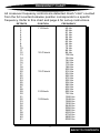
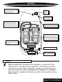
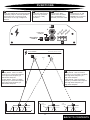
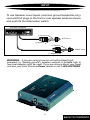
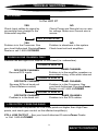
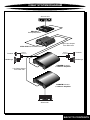
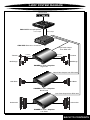
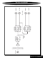
TM
EPX223 Electronic Crossover OWNERS MANUAL POWER CLASS
CONTENTS
(click on a topic to view)
Congratulations
Functions
Features and Specifications
Input
Frequency Chart
Troubleshooting
Installation
2 Way System Design
Wiring
3 Way System Design
Wiring
Block Diagram
Functions
Warranty
Congratulations and thank you.....
for choosing PrecisionPower audio epuipment. At PrecisionPower we
proudly design, engineer and manufacture audio products at our facility in
Phoenix, Arizona. Our award winning engineering team utilizes innovative
technology to consistently deliver Absolutely State of the Art performance,
sound quality, reliability, and value. This PrecisionPower product reflects
our commitment to offer you unparalleled versatility and quality for years of
dependable service and listening enjoyment.
TM
S ervice
Do not attempt to service PrecisionPower products yourself.
Performing exploratory surgery on your audio equipment yourself
will void the warranty. Many parts of your PrecisionPower gear
are custom built to our specifications. Our factory parts are not
made available to anyone else nor are they for sale. Our goal
is to make sure that your PrecisionPower product will always
sound as good as the day it was purchased. Contact your
authorized PrecisionPower dealer about obtaining any warranty
service through PrecisionPower.(See Warranty insde back cover)
F O R YO U R R E C O R D S :
M o d e l
Serial Number
Purchase Date
C aution!
The extended use of a high powered audio system may
result in hearing loss or damage. While PrecisionPower
systems are capable of "Concert Level" volumes with
incredible accuracy, they are also designed for you to
enjoy at more reasonable levels all of the sonic subtleties
created by musicians. Please observe all local sound
ordinances.
BACK TO CONTENTS
FEATURES / SPECIFICATIONS
Dual 2-Way, or Single 3-Way Active Crossover
Linkwitz-Riley 12dB/octave Slopes
Integral 13 Hz Subsonic Filter
Input Attenuation
Detented Frequency Selection Controls
Gold RCA Input and Output connectors
PowerLock Power, Ground and Remote connector
PWM Power Supply
Designed and Handcrafted in the USA
Specifications
Signal-to-Noise Ratio
Total Harmonic Distortion (1KHz, 1VRMS)
Crossover Slopes:
>102dB
0.002%
12 dB/octave
Crossover Frequencies:
50Hz to 5kHz
Input Impedance
Maximum Output (10 KΩ Load)
Supply Voltage
Dimensions
10 KΩ
8 VRMS
11-15 VDC
5.125"W
7.020" L
1.813"H
1
BACK TO CONTENTS
FREQUENCY CHART
All crossover frequency controls are detented. Each "click" counted
from the full counterclockwise position corresponds to a specific
frequency. Refer to this chart and page 6 for set-up instructions.
DETENTS
POSITION
1
2
3
4
5
6
7
8
9
10
11
12
13
14
15
16
17
18
19
20
21
22
23
24
25
26
27
28
29
30
31
32
33
34
35
36
37
38
39
40
41
7 O'clock
FREQUENCY
10 O'clock
12 O'clock
2 O'clock
3 O'clock
49 Hz
50 Hz
51 Hz
52 Hz
54 Hz
58 Hz
62 Hz
66 Hz
72 Hz
78 Hz
86 Hz
96 Hz
108 Hz
124 Hz
144 Hz
162 Hz
178 Hz
188 Hz
200 Hz
216 Hz
234 Hz
252 Hz
276 Hz
302 Hz
336 Hz
380 Hz
436 Hz
502 Hz
592 Hz
752 Hz
1000 Hz
1248 Hz
1568 Hz
1930 Hz
2448 Hz
3056 Hz
3680 Hz
4352 Hz
4704 Hz
4890 Hz
5000 Hz
2
BACK TO CONTENTS
INSTALLATION / MOUNTING
NOTE:
Before beginning, disconnect the negative (-) terminal of the battery
to prevent an electrical short to ground. Reconnect the negative
terminal only after all connections have been made.
Mounting
To prevent damage to the crossover while driving, mount it in a
secure place. Choosing the appropriate location will depend
upon your vehicle and the complexity of your system design.
Typical mounting locations include the trunk and passenger
compartment (floor or under seat). Never mount the crossover
in a location that would subject it to immersion or exposure to
water.
Once a location has been chosen, securely mount the
EPX-223 with four mounting screws. Be Careful! Inspect the
area underneath to be sure you are not drilling into wires, brake
or fuel lines, etc. that could be damaged by the drill bit or screws.
7.020
Dimensions
5.125"W
7.020"L
1.813"H
4.415
6.646
3
BACK TO CONTENTS
WIRING
Factory Ground wire may
need to be replaced if it is
frayed or broken.
Positive
Battery
Terminal
Fuse must be
installed within
18" of battery
Run signal cables (RCAs)
and remote turn-on lead
down the opposite side of
the vehicle from the power
wire to avoid radiated noise.
eject
BASS
LEFT
1
2
5
6
3
4
7
8
Trk 1
TREBLE
BALANCE
VOLUME
TRACK
RIGHT
FOWARD
PPI
MAR
KET
ING
Drill a hole in the firewall
and use a rubber grommet
to keep wire from shorting.
DPT
REVERSE
Run the cables under the
carpet near the side of the
vehicle. Be careful not to
drill or screw into the wires
when you replace the trim.
Avoid sharp edges that
could chafe through the
insulation.
Power distribution block.
Attach Ground Wires
firmly to solid metal.
NOTE
Before beginning, disconnect the negative (-) terminal of the
battery prior to working on the positive (+) terminal to prevent
a short to ground. This is important, unless you want to spend
the rest of your life with a nickname like "Sparky," or "Smokey."
Reconnect the negative terminal only after all connections have
been made.
4
BACK TO CONTENTS
WIRING
The next step is to connect the Power, Ground, and Remote wires to
your EPX-223. The power wire should run from the mounting location
through the vehicle to the battery or power distribution block. Avoid
sharp corners, creases, and sharp body parts. When passing through
any metal wall (i.e. firewall etc.), a grommet must be used to prevent
the wire from chaffing and shorting to ground.
The ground wire should be of the same gauge as the power wire. As
a rule of thumb, use as short a length of wire as possible.
Find a location near the crossover that is metal (the floor is ideal) and
clean an area about the size of a quarter to bare metal. Drill a pilot
hole in the middle of this area. Be Careful! Inspect the area underneath
to be sure you are not drilling into wires, brake or fuel lines, etc.
Terminate the wire with a ring connector and attach it to the bare
metal using a #8 sheet metal screw and washer (not supplied). We
suggest crimping and/or soldering this connection. After the connection
is complete, coat the area with silicone or some similar material to
Powerlock
prevent rust from developing.
Finally, the remote wire needs to
Remote
Power
Ground
run to the power antenna (or
amplifier remote) lead of the head
unit. This wire supplies a 12 volt
signal to the EPX-223 when the
T/O B+
main system is activated.
Once you have routed the power,
ground, and remote wires through
the vehicle, it is time to connect the wires to the EPX-223. Be sure
that you have not reconnected the ground cable to the negative post
of the battery.
Cut off excess wire and, using wire strippers, strip the power, ground
and remote cables about 1/8 inch. Locate the power, ground, and
remote Powerlock connector (supplied). On the top of the connector
are three slotted screws. With a small flat-bladed screwdriver, loosen
the screws before attempting to insert the cables. After you have
inserted the stripped end of each cable into the connector, secure it
by tightening the associated screw. Check that each connection is
tight. If the wires are secure, the connector may be plugged into the
EPX-223.
5
BACK TO CONTENTS
FUNCTIONS
1
2 3-Way/2-Way Switch:
-12dB Input Attenuation Switch:
Push this switch IN for high level input
capability. May be used for speaker
level input from common ground
head units or for high voltage line
drivers.
3 RCA Inputs:
Connect the RCA
cables from the head
unit, preamplifier, or
another processor here.
Push this switch IN for
dual 2-way operation,
or OUT for 3-Way
operation.
4
Connect Ground,
Remote turn on and
Power wires to the
PowerLock connector
and plug it in here.
3
Input
L
nd ote er
u
ro m w
G Re Po
3 way•out
2 way•in
R
attenuation
-12dB in
1
2
4
PrecisionPower
Two/Three Way Electronic Crossover
EPX-223
Made In USA
5
6
220
220
600
100
Power
50
5K
600
100
50
Low Pass Freq.
5K
High Pass Freq.
5
6 High Pass
2-Way Mode: Sets Low Pass
frequency to Low Pass 2 Outputs,
and High Pass frequency to
High Pass Outputs.
3-Way Mode: Sets Low Pass
frequency to Band Pass Outputs,
and High Pass frequency to
High Pass Outputs.
Low Pass
2-Way Mode: Sets Low Pass
frequency to Low Pass Outputs,
and High Pass frequency to
Band Pass Outputs.
3-Way Mode: Sets Low Pass
frequency to Low Pass Outputs,
and High Pass frequency to
Band Pass Outputs.
Amplitude
Amplitude
5
Low Pass
Three-Way Mode
Band Pass
6
13Hz
Sub Sonic
High Pass
5
Low Pass
6
6
13Hz
Sub Sonic
Band Pass
Low Pass 2
High Pass
Two-Way Mode
BACK TO CONTENTS
FUNCTIONS
Amplitude
Amplitude
5
Low Pass
13Hz
Band Pass
6
5
13Hz
Sub Sonic
High Pass
50Hz to 5kHz 50Hz to 5kHz
Low Pass
Frequency
13Hz
6
13Hz
Sub Sonic
Band Pass
50Hz to 5kHz
Three-Way Mode
Low Pass 2
13Hz
High Pass
50Hz to 5kHz
Frequency
Two-Way Mode
Outputs
L
L
L
L
R
R
R
R
Low Pass 2
High Pass
Band Pass
TO ACTIVELY CROSS THESE SPEAKERS:
Low Pass
USE THESE OUTPUTS:
Low Pass / Bandpass / High Pass
Subwoofer / Mid Range / Tweeters
Subwoofer / Mid Bass / Full Range
Subwoofer / Full Range
Low Pass / Bandpass or
Low Pass 2 / High Pass, or both
7
BACK TO CONTENTS
INPUT
To use Speaker Level Inputs (common ground headunits only),
connect RCA plugs to the front or rear speaker leads as shown,
and push IN the Attenuation switch.
SOURCE Headunit
eject
BASS
LEFT
1
2
3
4
5
6
7
8
Trk 1
TREBLE
BALANCE
VOLUME
TRACK
RIGHT
FOWARD
PPI
MAR
KET
ING
DPT
REVERSE
(+) Positive
LEFT input
(-) Negative
(+) Positive
RIGHT input
(-) Negative
WARNING: If you are using a source unit with bridged high
powered (or "floating ground") speaker outputs, a suitable high to
low level adapter must be used. If you are unsure about your head
unit see your local PrecisionPower dealer or call 1-800-62POWER.
8
BACK TO CONTENTS
TROUBLE SHOOTING
NO SOUND
Is the LED lit?
YES
Check Input cables for signal by
connecting them straight to the
Subwoofer amplifier
NO
Check Power and Remote turn-on wire
for voltage. Make sure Ground wire is
secure.
ANY SOUND NOW?
YES
Problem is in the Crossover. See
your local Authorized PrecisionPower
Dealer or call 1-800-62POWER.
NO
Problem is elsewhere in the system.
Check head unit and amplifiers.
SOUND IN ONE CHANNEL ONLY
Reverse left and right RCA outputs for one band (i.e. subwoofers).
SOUND IS NOW IN
OPPOSITE CHANNEL
Reverse RCA inputs
SAME CHANNEL
Problem is in the amplifier, speakers or
associated wiring of the silent channel.
SOUND IS NOW IN
SAME CHANNEL
Problem is in the Crossover. See
your local Authorized PrecisionPower
Dealer or call 1-800-62POWER.
SOUND IS NOW IN
OPPOSITE CHANNEL
Reverse RCAs at head unit
(Check Balance control)
OPPOSITE CHANNEL
Problem is in the head unit
SAME CHANNEL
Problem is in the RCA cables
LOW OUTPUT FROM ONE BAND
Check crossover frequencies for Low Pass points set higher than High Pass
points, and check gain control on the affected amplifier(s).
STILL LOW OUTPUT - See your local Authorized PrecisionPower Dealer
or Call 1-800-62POWER.
9
BACK TO CONTENTS
2-WAY SYSTEM DIAGRAM
Source Unit
eject
BASS
1
2
5
6
4
7
8
Trk 1
PPI
TRACK
RIGHT
LEFT
3
TREBLE
BALANCE
VOLUME
FOWARD
MAR
KET
ING
DPT
REVERSE
PEQ-114
Preamp/Equalizer
60
0
ver
A
sso
ic Cro e in US
tron
Mad
y Elec
Wa
50
Po
w
er
0
60
0
22
0
5K
10
50
3 way
atte
nua
tion
-12dB
in
L
Le
ft
Ph
as
e
EPX-
Ri
gh
t Ph
as
e
10
0
5K
22
0
ee
/Thr
Two
r
Powe
cision 223
Pre
Inp
ut
ision
r
we
Po
Prec
•ou
2 way t
•in
R
nd e
Grou Remot wer
Po
High Pass Output
from EPX-223
EPX-223 Electronic Crossover
Tweeter
Passive
Crossover
Passive
Crossover
MidRange
Tweeter
MidRange
POWERCLASS™
2 channel Amplifier
Low Pass Output
from EPX-223
POWERCLASS™
2 channel Amplifier
Subwoofer
10
BACK TO CONTENTS
3-WAY SYSTEM DIAGRAM
Source Unit
eject
BASS
1
2
5
6
3
4
7
8
Trk 1
TREBLE
BALANCE
VOLUME
FOWARD
MAR
PPI
TRACK
RIGHT
LEFT
KET
ING
DPT
REVERSE
PAR-245 Preamp/Equalizer
Front Output
Rear Output
60
0
ver
A
sso
ic Cro e in US
tron
Mad
y Elec
Wa
50
Po
w
er
0
60
0
22
50
10
0
5K
22
EPX-
nua
tion
-12dB
in
L
Le
ft
Ph
as
e
Pre
3 way
atte
Ri
gh
t Ph
as
e
10
0
5K
22
0
ee
/Thr
Two
r
Powe
3
cision
Inp
r
we
Po
ision
ut
Prec
•ou
2 way t
•in
R
nd e
Grou Remot wer
Po
EPX-223 Electronic Crossover
High Pass Output
from EPX-223
Tweeter
Passive
Crossover
Passive
Crossover
MidRange
Tweeter
MidRange
POWERCLASS™ Amplifier
High Pass
Band Pass Output from EPX-223
Mid Bass
Mid Bass
POWERCLASS™ Amplifier
Band Pass
Low Pass Output from EPX-223
Subwoofer
Subwoofer
POWERCLASS™ Amplifier
Low Pass
11
BACK TO CONTENTS
RCA Input
Diff.
3-Way/2-Way
Switch
12dB / octave
13 Hz
High Pass
Subsonic Filter
12dB / octave
Low Pass
50Hz - 5KHz
High Pass
Low Pass
12dB / octave
Low Pass
50Hz - 5KHz
High Pass
High Pass
RCA Outputs
Low Pass
Band Pass
Low Pass 2
High Pass
BLOCK DIAGRAM
-12dB INPUT ATTENUATION
12
BACK TO CONTENTS
WA R R A N T Y
Three-Year Limited U.S.A. Warranty
This warranty gives you specific legal rights, and you may also have other rights which vary from
state to state. PrecisionPower warrants its products to be free from defects in materials and
workmanship under normal use and service for a period of three (3) years from the date of
original purchase when the unit is installed by an Authorized Dealer. Non-Authorized Dealer
installed products carry a one (1) year parts and ninety (90) days labor limited warranty. The
extent and conditions of Limited Warranty are as follows:
1. Authorized Dealer Installed Products: PrecisionPower will either repair or replace at no charge,
to the original purchaser, any unit which PrecisionPower’s examination discloses to be defective
and under warranty, provided the defect occurs within three (3) years from the date of original
purchase when the unit is installed by an Authorized Dealer and the product is returned immediately to PrecisionPower. This warranty is not transferable.
2. Non-Authorized Dealer Installed Products: PrecisionPower will either repair or replace at no
charge, to the original purchaser, any unit which PrecisionPower’s examination discloses to be
defective and under warranty, provided the defect occurs within ninety (90) days from the date of
purchase and the product is returned immediately to PrecisionPower. Warranty claims beyond
ninety (90) days for Non-Authorized Dealer Installed Products will be for parts only and will
extend for one (1) year from the date of purchase. This warranty is not transferable.
3. The date of purchase and proof of Authorized Dealer Installation of a PrecisionPower product
must be established by an original sales receipt which must accompany the article being returned for warranty work.
4. This warranty shall NOT apply to any PrecisionPower product found to have the original factory serial number removed or defaced. All products received (by PrecisionPower) for in warranty or out of warranty repair, with their original serial numbers removed or defaced, will NOT be
repaired and will be returned to sender, freight collect. Refer to original packaging for the serial
number of your component speakers.
5. The provisions of this warranty shall not apply to any PrecisionPower product used for a
purpose for which it is not designed, which has been repaired or altered in any way, or which has
been connected, installed, or adjusted other than in accordance with the instructions furnished in
PrecisionPower’s owner’s manual. Nor shall this warranty apply to any part which has been
subject to misuse, neglect, or accident.
6. PrecisionPower does not authorize any other persons to assume any other liability in connection with its products. THIS WARRANTY IS THE ONLY EXPRESS WARRANTY MADE BY
PRECISIONPOWER APPLICABLE TO ITS PRODUCTS. ANY IMPLIED WARRANTY OR MERCHANTABILITY OR FITNESS FOR A PARTICULAR PURPOSE APPLICABLE TO
PRECISIONPOWER PRODUCTS IS LIMITED IN DURATION TO THE DURATION OF THIS
LIMITED WARRANTY. PRECISIONPOWER SHALL NOT BE LIABLE FOR THE INCIDENTAL,
CONSEQUENTIAL, OR COMMERCIAL DAMAGES RESULTING FROM THE BREACH OF THIS
WRITTEN WARRANTY. Some states or provinces do not allow the exclusion or limitation of
incidental or consequential damages or limitations on how long an implied warranty lasts; so the
above limitations or exclusions may not apply to you.
7. Your product will be serviced on an in-warranty basis within the warranty period for the correction of warranted defects. If improper operation of your PrecisionPower product should occur,
contact your Authorized Dealer for assistance with the return and factory repair of your
PrecisionPower
product. If an Authorized Dealer is not available, return the unit including your name, telephone
number, return address, a copy of your sales receipt, and a description of the problem to:
PrecisionPower,Inc.
Service Department
4829 S. 38th Street
Phoenix, AZ 85040-2964
TO RETURN PRECISIONPOWER PRODUCTS OUT OF WARRANTY: Return the unit, postage
prepaid, in the original protective carton. Please include a description of the problem and, if
desired, a request for an estimate of repair costs. Unless a request for an estimate is included,
the unit will be repaired as necessary. Please contact PrecisionPower Customer Service at 1800-62-POWER for questions concerning out of warranty repair charges. Repaired unit will be
returned with an itemized statement, C.O.D.
BACK TO CONTENTS