1
Meshdynamics Network Viewer User Guide
Network Viewer Release 9.0
Meshdynamics, Inc.
2953 Bunker Hill Lane Ste 400
Santa Clara, CA 95054
USA
http://www.meshdynamics.com
THE SPECIFICATIONS AND INFORMATION REGARDING THE PRODUCTS IN THIS MANUAL ARE SUBJECT TO CHANGE
WITHOUT NOTICE. ALL STATEMENTS, INFORMATION, AND RECOMMENDATIONS IN THIS MANUAL ARE BELIEVED TO BE
ACCURATE BUT ARE PRESENTED WITHOUT WARRANTY OF ANY KIND, EXPRESS OR IMPLIED. USERS MUST TAKE FULL
RESPONSIBILITY FOR THEIR APPLICATION OF ANY PRODUCTS.
THE SOFTWARE LICENSE AND LIMITED WARRANTY FOR THE ACCOMPANYING PRODUCT ARE SET FORTH IN THE
INFORMATION PACKET THAT SHIPPED WITH THE PRODUCT AND ARE INCORPORATED HEREIN BY THIS REFERENCE. IF YOU
ARE UNABLE TO LOCATE THE SOFTWARE LICENSE OR LIMITED WARRANTY, CONTACT YOUR MESHDYNAMICS
REPRESENTATIVE FOR A COPY.
The performance testing tool in the MD4000 family of products and the Network Viewer uses Iperf, a program developed by
the University of Illinois. Copyright © 1999-2008, The board of trustees of the University of Illinois. For more information
please visit http://dast.nlanr.net/Projects/Iperf/ui_license.html
The Network Viewer uses geographic map data from OpenStreetMap. OpenStreetMap is a free editable map of the whole
world. Fore more information please visit http://www.openstreetmap.org.
The Network Viewer uses Java™. Java™ is a registered trademark of Sun Microsystems. For more information please visit
http://java.sun.com.
THIS COMPUTER PROGRAM AND UNDERLYING CONCEPTS ARE PROTECTED BY PATENT AND COPYRIGHT LAWS.
UNAUTHORIZED REPRODUCTION OR DISTRIBUTION OF THIS PROGRAM, OR ANY PORTION OF IT, MAY RESULT IN SEVERE
CIVIL AND CRIMINAL PENALTIES AND WILL BE PROSECUTED TO THE MAXIMUM EXTENT.
THE SOFTWARE IS PROVIDED "AS IS", WITHOUT WARRANTY OF ANY KIND, EXPRESS OR IMPLIED, INCLUDING BUT NOT
LIMITED TO THE WARRANTIES OF MERCHANTABILITY, FITNESS FOR A PARTICULAR PURPOSE AND NONINFRINGEMENT. IN
NO EVENT SHALL THE CONTRIBUTORS OR COPYRIGHT HOLDERS BE LIABLE FOR ANY CLAIM, DAMAGES OR OTHER
LIABILITY, WHETHER IN AN ACTION OF CONTRACT, TORT OR OTHERWISE, ARISING FROM, OUT OF OR IN CONNECTION
WITH THE SOFTWARE OR THE USE OR OTHER DEALINGS IN THE SOFTWARE.
All other trademarks mentioned in this document or the Meshdynamics website are the property of their respective owners.
Structured Mesh™, Modular Mesh™, MeshControl™, P3M™, PBV™ are trademarks of Meshdynamics, Inc.
Meshdynamics Network Viewer 9.0 User Guide.
Copyright © 2002-2010 Meshdynamics, Inc. All rights reserved.
Contents
Preface
Terminology
04
05
Network Viewer Software Installation
06
Starting the Network Viewer
Network Viewer Screen Layout
Status Window Tabs
Viewing Node Status
Link Values
Changing Node Display Settings
07
08
09
11
12
13
Node Configuration
Advanced Node Configuration
15
23
Network Management Security
30
Macro
Macro
Macro
Macro
Macro
32
33
34
35
36
Actions
Actions
Actions
Actions
Actions
:
:
:
:
:
Overview
Moving Nodes
Automate Configuration
Firmware Update
PBV™ Settings
Network Views, Adding Background Images etc
37
Remote Management
40
Performance Measurement
RF Space Information
FIPS 140-2 Wizard
GPS Wizard
44
46
47
48
APPENDIX AND ADVANCED TOPICS
.
.
.
.
Step by Step Trouble Shooting Guide
MeshDynamics Channel Management (Overview)
MeshCommands - Command Line Interface.
NMS Application Programming Interface (API) and Scripting Interface
NETWORK VIEWER 9.0 © 2002-2010 Meshdynamics, Inc. All Rights Reserved. Email: [email protected]
3
Preface
Audience
This guide is for the networking professional who installs and manages Meshdynamics MD4000 mesh nodes. To use this guide, you
should be familiar with the concepts and terminology of wireless local area networks.
Purpose
This guide provides the information to configure your MD4000 mesh nodes. This guide provides the procedures for using the
Meshdynamics Network Viewer commands that have been created or changed for use with the MD4000 mesh node.
Related Links
Meshdynamics NMS Videos on Youtube: www.meshdynamics.com/MDWEBCASTS.html
Meshdynamics MD4000 NMS Viewer Web Page: www.meshdynamics.com/Mesh-Network-Manager.html
Meshdynamics MD4000 Hardware Installation Guide: www.meshdynamics.com/documents/MD4000_HWMANUAL.PDF
Meshdynamics MD4000 Mesh Command Manual www.meshdynamics.com/documents/MD4000_MESHCOMMANDS.pdf
Other Documentation
All Meshdynamics documentation and additional literature are available on our website at:
www.meshdynamics.com/tech-presentations.html
.
NETWORK VIEWER 9.0 © 2002-2010 Meshdynamics, Inc. All Rights Reserved. Email: [email protected]
4
Terminology
Wireless
RELAY 2
Backhaul
RELAY 1
Ethernet
Root and Relay Nodes
Mesh Networks provide long range connectivity by relaying packets from one mesh node to another, like a bucket brigade. The end of the
bucket brigade terminates at the root – which connects to the Ethernet. (above) Relays connect to the root or other relay nodes to form a
wirelessly linked chain.
Upstream & Downstream
Upstream implies closer to the Ethernet. The root is upstream of relay 1.
Wireless Uplinks and Downlinks.
Ethernet
The Ethernet link is the uplink (upstream link) connection for the root. The root has is
a wired uplink. Its ‘backhaul’ is the wired network.
ROOT
DOWNLINK
Relays have wireless uplinks through a upstream downlink radio.
Downlink radios act like Access Points (AP) : they send out a beacon. Uplink radios act
like clients – they do not send out a beacon.
A wireless radio card in the laptop can inform you of the presence of downlinks but not
of uplinks. Downlinks beacon, Uplinks do not.
UPLINK
SERVICE
RELAY
The uplink and downlink radios form a wireless backhaul path.
AP radios
operate in the 2.4GHz band to service 11b/g clients. 802.11a wireless
devices may be serviced by the 5.8GHz downlink.
Thus, both 802.11a and 802.11b/g client access is supported.
Backhaul radios operate in 802.11a 5.8GHz band to avoid interference with the
802.11b/g 2.4GHz AP radios (pink, right).
To summarize, there are 4 types of ‘links’ in Structured Mesh™ products:
A wired uplink to provide Ethernet connectivity. This connects the ROOT node to the wired network.
A wireless downlink to provide wireless connectivity. Acts like an AP for the uplink. Typically 5.8GHz.
A wireless uplink to connect to upstream mesh nodes. This is a ‘client’ to the downlink. Typically 5.8GHz.
An AP radio for clients. Typically 2.4GHz with support for both b and g clients.
NETWORK VIEWER 9.0 © 2002-2010 Meshdynamics, Inc. All Rights Reserved. Email: [email protected]
5
Installing the Network Viewer Software
Prior to MeshDynamics Network Viewer Software Installation
Please ensure that the mesh nodes are set up as shown below.
NMS Running Here
ROOT
Downlink
Uplink
1. A DHCP server connected to SWITCH1.
2. The ROOT mesh node is also connected to SWITCH1.
RELAY
Downlink
3. The RELAY mesh nodes form a chain ending at the ROOT node.
These mesh nodes make all the wireless stations that connect to service radios on the mesh node (not
shown) appear to be on the same LAN as the DHCP server and the Firewall/Router.
Uplink
4. The Mesh Nodes are all Layer 2 transparent bridges, and compatible with LAYER 3 protocol and
policy software. They are transparent to Layer 3 and above protocols and applications
RELAY
5. Wireless stations connecting to the mesh nodes are assigned IP addresses by the DHCP server.
6. You may also elect to not have a DHCP server if the workstations are assigned static IP addresses.
Installing the Network Viewer Software
1. The Network Viewer must run from a machine on wired side of the network as shown above (the encircled laptop). It is
possible to run the Network Viewer from the wireless side of the network, but does not guarantee optimal performance and is
strongly discouraged.
2. The Network Viewer requires Java SE 6 Runtime Environment to be installed. This may be downloaded from:
http://java.sun.com/javase/downloads/index.jsp (select the Java Runtime Environment (JRE) 6 link).
3. The Network Viewer software is downloaded from the reference site supplied in the documents shipped with your mesh products.
NETWORK VIEWER 9.0 © 2002-2010 Meshdynamics, Inc. All Rights Reserved. Email: [email protected]
6
Starting the Network Viewer
Click on the green ‘Start’ button to start the Network Viewer (below).
Wired Link
Power up the root node and wait 1-2 minutes. The root
node’s icon appears on the Network Screen on booting up.
Root Node
There is a thick black line from the icon to the edge of the
screen, signifying a wired connection to the network.
Next, power the relay nodes. After 1-2 minutes, the relay node icons also appear on the screen (below). The icons initially appear in a
cluster, however, they can be moved to desired locations by clicking and dragging.
1. Click/drag nodes
2. Save Settings
Heart beat Status Updates
Each relay node icon will have a blue line that connects it to its parent node. The blue ‘connector’ lines represent the backhaul of the
mesh. This is the path information takes to or from the Internet. There will also be a web of gray dotted lines between the node icons.
These lines represent the awareness a child node has of its potential parent nodes.
There may be a number of possible parent nodes for a particular child node, but the child node will dynamically choose the best path to
the root node (This does not necessarily mean the fewest number of hops).
The mesh nodes are periodically sending status information (‘heartbeats’). When they are received by the Network Viewer, the screens
are updated. However, the mesh network does not require the Network Viewer to be running. To confirm this:
1.
2.
3.
4.
Save the screen view. Use either the File menu or the toolbar save icon.
Stop the Network Viewer and quit the application.
Note that the mesh network continues to operate, regardless of whether the Network Viewer is running or not running.
Activate the application again and start the Viewer. The Network Viewer Heart beat window is updated as heart beats are received.
NETWORK VIEWER 9.0 © 2002-2010 Meshdynamics, Inc. All Rights Reserved. Email: [email protected]
7
Network Viewer Screen Layout
The Network Viewer is composed of three interrelated information elements:
B
ROOT
Properties List
for a Selected
Node
A
Network
View
RELAY
C
Status Window
A
The Network View
The Network View is where both logical (topology view) and physical (map view) relationships between the nodes is shown. These
different view types are described later. Parent-child relationships are depicted by connecting lines. Node status updates change
LED and node icon channel values. The network screen supports multiple network displays, each with its own tab.
B
The Properties List
All pertinent information for a selected node is available at a glance on the Properties List. This includes hardware information, MAC
addresses, IP settings, AP information, etc. This information is refreshed with each new heartbeat update from each node.
C
Status Window
Dynamic information about the active network is posted in the Status Window.
Signal strength and transmit rates between nodes can be monitored here along with other information sent by nodes via periodic
heartbeat updates.
The Status Update Window contains 6 tabs: Alerts, Networks, Heartbeat, Macro actions, Client/Station Activity and Meshdynamics
PBVTM status tab. These are described next.
NETWORK VIEWER 9.0 © 2002-2010 Meshdynamics, Inc. All Rights Reserved. Email: [email protected]
8
Status Window Tabs
A
B
C
D
A
The ‘Alerts’ tab is used to alert the user of important events occurring on the network.
Each alert is shown with a level indicator on the left.
There are three levels of alerts : Red (High importance)
, Orange (Medium importance)
, Yellow (Low importance)
.
The user can filter the level of alerts by clicking the appropriate buttons near the top.
B
The ‘Networks’ tab provides a summary of all open networks in the Network Viewer.
C
A ‘heartbeat’ is an information packet broadcast by each node in the network. The last received heart beat is highlighted (blue).
The ‘HeartBeat’ tab in the Status Window contains a list of all active nodes on the network (above)
Information about each node is updated with each passing heartbeat from that node. The ‘Time Stamp’ column displays the date and
time of the last heartbeat. The heartbeat may be temporarily changed to as low as 1 per second – this is particularly useful when
antennas are being aligned for best reception. Restore the value to between 10-20 seconds after the alignment is completed. Adjusting
heartbeat rate is described under Node Configuration.
Note that the root node will not possess any such uplink information or parent information, since it has no parent node.
D
The ‘Macro Actions’ of the nodes are updated with heartbeats as well. Macro actions pertain to actions performed on a user-selectable
group of nodes. Group Selections and Macro Actions are described later on Page 31.
NETWORK VIEWER 9.0 © 2002-2010 Meshdynamics, Inc. All Rights Reserved. Email: [email protected]
9
Status Window Tabs
E
E
F
The ‘Client Activity’ tab provides information about standard
802.11 clients connected to the nodes.
By default it shows the Upstream Rate and the Received Signal
strength information for each client in a list
ordered by the mesh nodes.
To get more information the ‘Client Activity’ option needs to be enabled on the nodes. To enable ‘Client Activity’ go to the ‘Tools’ menu
and select ‘Show Client Activity’.
Add the desired nodes to the ‘Client Activity Enabled’ list and press OK. The ‘Client Activity’ tab now shows additional information for
the selected nodes.
Note: When finished viewing client activity, disable the nodes from STA Activity List . This reduces needless traffic over the backhaul.
F
The PBV™ tab allows management and monitoring of the Meshdynamics Persistent Baseline Voice (PBV™) option.
PBV™ is a software option available on Meshdynamics MD4000 mesh nodes. When enabled, PBV™ provides an out-of-the-box PBX for
SIP compliant VOIP phones.
For more information please refer to Page 27.
NETWORK VIEWER 9.0 © 2002-2010 Meshdynamics, Inc. All Rights Reserved. Email: [email protected]
10
Viewing Node Status
1
Double-click on any node icon to bring up the node’s information in the Properties Window (left of the
Network screen). There will also be a check mark in the node icon’s message window indicating selection.
2
Right-click on the node icon’s message window to change the display. Options for display are: node name,
uplink transmit rate (Mbps), signal strength of parent downlink (dBm), board temperature, and node
configuration (4350, 4455, etc). Setting the default description is described in a later section.
3
Mouse over the LEDs on top of the Text Box. Tool tip text shown relates to specific parameter of the node e.g.
signal strength, transmit rate, temperature, etc. This text is updated every heartbeat.
4
Mouse over the blue boxes below the Text box. Tool tip text shown relates to the channel of a radio. This text
is updated every heartbeat and will change based on which parent’s downlink the uplink radio connects to.
3
1
2
4
Port Indicators: Along the bottom of the node icons are Port indicators. Each indicator represents a different wireless or wired link.
Wireless links are labeled Wlan0, Wlan1, WLan2. Ethernet (wired) links are Ixp0 and Ixp1. Note that the root node icons do not have a
wlan1. Root nodes have a wired uplink connection to the Internet via ixp0 (left Ethernet port).
Wired and Wireless Port Indicators
E
B
D C A
A
wlan0………Downlink Radio
B
wlan1………Uplink Radio
C
wlan2………Service Radio
D
ixp1…………Right Ethernet Port
E
ixp0………… Left Ethernet Port
Uplink for Root Node
Channel Numbers for Uplink and Downlinks: Move the cursor over the channel indicators to see the channel of a particular wlan.
Notiice that a child uplink rado (wlan1) will be on the same channel as its parent’s downlink (wlan0), as would be expected.
Parent downlink
Child uplink
Minimizing the node display: Click on the the ‘minimize’ button [5] on the node
icon to shrink the icon into a dot (convenient for highly populated Network Screens).
Double-click on the dot to bring the icon back to its original size.
To minimize all nodes right-click the network tab and select ‘Minimize All Nodes’ [6]
5
6
NETWORK VIEWER 9.0 © 2002-2010 Meshdynamics, Inc. All Rights Reserved. Email: [email protected]
11
Link Values
Each Link Has Four Associated Values: Parent Downlink Signal + Rate , Uplink Signal + Rate
When booting up a mesh for the first time, it is good practice to boot up the ROOT node(s) first, then the first (closest) RELAY, then the
next closest RELAY, and so on. The Network Viewer will display information about the links under the Heartbeat tab when the nodes boot
up. This information can be used to troubleshoot the link (if necessary). The four values associated to each link are explained below.
Parent Downlink Signal
This is the signal strength that a particular child node sees from its parent node. Keep in mind that this will vary from child-to-child, as child
nodes are typically located at different distances from the parent node. This also depends on the antennas used in the link. A child node
with a high-gain antenna on its uplink will “see” a stronger signal from the parent node than if a lower-gain antenna was used. This is
because the higher gain antenna will have a higher receive sensitivity. Conversely, putting a higher gain antenna on the parent node’s
downlink will result in the child nodes “seeing” a stronger signal from the parent.
Parent Downlink Rate
This is the connectivity in the direction of parent-node-to-child-node. Again, each child node will have its own value for ‘Parent Downlink
Rate’
Uplink Signal
This is the signal strength of a node’s uplink as seen by its parent node. Keep in mind that this value depends on each antenna used in the
link. A child node with a high-gain antenna on its uplink will transmit a stronger signal to the parent node than if a lower-gain antenna was
used. Conversely, putting a higher gain antenna on the parent node’s downlink will result in the parent node “seeing” a stronger signal from
the parent since the higher gain antenna will have a higher receive sensitivity.
Uplink Rate
This is the connectivity in the direction of child-node-to-parent-node.
The two values displayed on the neighbor lines in between nodes are the “Uplink Rate”, and the “Parent Downlink Signal
NETWORK VIEWER 9.0 © 2002-2010 Meshdynamics, Inc. All Rights Reserved. Email: [email protected]
12
Changing Node Display Settings
There are three LEDs across the top of the node icons:
A
On/Off. This LED is yellow when node is running. It is grayed, when the node is inactive.
B
LED1. This LED can be set dynamically every ‘heartbeat’ by Alert scripts in the ‘AlertScripts’ folder. The LED
C
LED2. This performs the same function as LED1.
A
B
C
can be either GRAY: off, RED: critical issue, YELLOW: medium issue or GREEN: healthy.
The ‘AlertScripts’ folder can contain programmable scripts written in Ruby or JavaScript.
For more information please refer to Page 49.
To configure the default text displayed on a node, click on ‘View Settings’ on the ‘View Menu’.
Node Text message Window
Choose from the list next to where it reads ‘Node Display Text’. The default is the node model number.
Options for display are: node name, uplink transmit rate (Mbps), signal strength of parent downlink (dBm), board temperature,
board voltage, and node configuration (4350, 4455, etc.).
Note: This option controls all node icon message windows on the Network Screen. To change an individual node text display,
bring the cursor over top of the Node Text message window and right-click.
NETWORK VIEWER 9.0 © 2002-2010 Meshdynamics, Inc. All Rights Reserved. Email: [email protected]
13
Node Settings
A node can be configured by right-clicking
the node’s icon and choosing one of the
following from the ‘Settings’ sub-menu:
• Configuration
• Advanced
Configuration
This command allows configuration of the following:
• Node’s identification parameters e.g. Name, IP address, etc
• The radio level settings for each interface on the node e.g. ESSID, Transmit Power, etc
• The authentication and encryption settings for each interface on the node.
• Virtual LAN and Access Control Lists
Pages 15 through 22 describe the parameters in more detail.
Advanced Options
This command allows configuration of the following:
• Per-packet QoS policy using Meshdynamics Effistream™ technology
• 802.11e EDCA category settings
• IGMP snooping
• Meshdynamics P3M™ technology
• Meshdynamics PBV™ technology
• Custom frequency using Meshdynamics RF Editor™
Pages 23 through 31 describe each of the parameters in more detail.
Batch configuration of a set of nodes
For automatically applying one node’s configuration to all the nodes on your network, refer to Macro Actions on Page 32.
NETWORK VIEWER 9.0 © 2002-2010 Meshdynamics, Inc. All Rights Reserved. Email: [email protected]
14
Node Configuration : General
A
The ‘Node Name’ is a label for the node which will
appear inside the node icon’s message window as
well as in the Properties List
A
E
B
The ‘Country Code’ determines the channels at
which the node operates. ‘Country Code’ should
not be changed unless appropriate.
B
The IP address and Gateway must be on the on
same subnet.
C
D
‘Preferred Parent’ is the upstream node of choice.
‘Heartbeat Interval’ is the rate at which nodes
broadcasts its information to the NMS/other nodes.
It may be temporarily changed to 1-2 seconds to
help with antenna alignment/diagnostics. Normal
range of 10-20 seconds is suggested.
E
C
D
F
‘GPS Coordinates’
The Latitude and Longitude coordinates of the node can be entered in decimal form.
For Latitude, coordinates north of the equator are positive and south of the equator are negative numbers.
For Longitude, coordinates east of the meridian are positive, and west of the meridian are negative.
Note: This sets the default coordinates of the node. If the node is equipped with the GPS option, the coordinates reported in the
heartbeat shall be updated automatically. The default coordinates are used if the node does not have a GPS.
F
‘Mobility Mode’ can be set to :
• Stationary
• Mobile Infrastructure (for stationary nodes that will serve as infrastructure for mobile nodes).
• Mobile (for mobile nodes).
For Units with the optional Scanner radio, the ‘Mobile’ mode enables the node’s mesh algorithm to become more dynamic with respect
to its environment.
For stationary nodes that act as Infrastructure to mobile nodes, the ‘Mobile Infrastructure’ mode optimizes the network performance
parameters for mobile child nodes.
NETWORK VIEWER 9.0 © 2002-2010 Meshdynamics, Inc. All Rights Reserved. Email: [email protected]
15
Node Configuration : Interfaces
The ‘Interfaces’ tab of the Node Configuration window allows the user to control the behavior of each radio in the node.
1
2
To modify a radio, first select which radio is to be
modified by clicking on the appropriate button to
the right of the wording
1
In selecting either the Downlink radio, or the Access Point radio, more options will appear in the lower part of the window.
2
ACK timeout is increased when the
distance of the radios exceeds
default IEEE 802.11 settings
Options for client connectivity:
When unchecked only Mesh nodes
can connect through the interface.
Hides the ESSID
(blank ESSID in
beacons)
‘Dynamic Channel Management’ is
best set to ‘Auto’. Nodes choose
channel with least RF interference
NETWORK VIEWER 9.0 © 2002-2010 Meshdynamics, Inc. All Rights Reserved. Email: [email protected]
16
Node Configuration : Security
Backhaul Security
The wireless links between Meshdynamics nodes
are automatically secured using hardware based
128-bit AES-CCM encryption.
128-bit AES-CCM Key 2
CCM is a block-cipher mode of AES that includes:
128-bit AES-CCM Key 1
128-bit AES-CCM Key 3
• Counter for replay protection
• Message authentication code for source
validation
Each link uses its own 128-bit temporal AES-CCM
key for securing transmissions.
The temporal keys are randomly generated at
the time of association.
Hence no settings are required for securing the
backhaul traffic.
Client Connections through Backhaul Radios
Standard 802.11 clients can connect through the backhaul radios, unless the ‘Allow Client Connection’ option is unchecked for the
backhaul downlink radios (See Page 16 for more information).
If ‘Allow Client Connection’ is checked, you are advised to configure a client access security scheme to prevent un-authorized access.
Client Access Security
The following client access security schemes are supported:
• Wired Equivalent Privacy (WEP-40 and WEP-104)
Provides basic privacy to wireless packets sent over-the-air, but is considered to be less secure when compared to the other security
schemes.
Since WEP was part of the original 802.11-1999 standard, it can assumed that most clients will support it.
• WPA Version 1 – Personal mode (a.k.a. WPA-PSK)
Requires users to authenticate using a shared pass-phrase. Supports both CCM and TKIP cipher schemes, with CCM being optional.
Since TKIP uses WEP as its underlying algorithm, it is considered less secure than CCM.
• WPA Version 1 – Enterprise mode (a.k.a. WPA-Radius)
Requires users to authenticate with a RADIUS server using EAP or PEAP. Supports both CCM and TKIP cipher schemes, with CCM being
optional.
• WPA Version 2 – Personal mode (a.k.a. WPA2-PSK or 802.11i-PSK)
Similar to WPA-PSK, but mandates CCM support on clients.
• WPA Version 2 – Enterprise mode (a.k.a. WPA2-Radius or 802.11i)
Similar to WPA-Radius, but mandates CCM support on clients.
NETWORK VIEWER 9.0 © 2002-2010 Meshdynamics, Inc. All Rights Reserved. Email: [email protected]
17
Node Configuration : Security
Setting up WEP Security
1
2
3
5
4
1
Select WEP from the list of options.
2
Choose the desired cipher strength (WEP-40 for 64 bit or WEP-104 for 128 bit).
3
Type in a pass-phrase and click on ‘Generate’ to automatically generate the keys.
4
One may also manually type the hexadecimal keys directly or edit the pass-phrase generated keys.
5
Choose the transmission key index (1 by default).
NETWORK VIEWER 9.0 © 2002-2010 Meshdynamics, Inc. All Rights Reserved. Email: [email protected]
18
Node Configuration : Security
Setting up WPA/WPA2 Personal Security
1
2
3
4
1
Select WPA Personal from the list of options.
2
Choose the desired mode (WPA or WPA2/802.11i)
3
Type in a pass-phrase and click ‘Generate’ to create the 256-bit PSK.
4
Select the desired encryption cipher (CCM or TKIP).
NETWORK VIEWER 9.0 © 2002-2010 Meshdynamics, Inc. All Rights Reserved. Email: [email protected]
19
Node Configuration : Security
Setting up WPA/WPA2 Enterprise Security
1
2
3
4
5
6
7
1
Select WPA Enterprise from the list of options.
2
Choose the desired mode (WPA or WPA2/802.11i)
3
Enter the IP address of the RADIUS server. (Note: The node’s IP address must be configured such that the RADIUS server is reachable
from the node).
4
Enter the RADIUS server listen port. (default: 1812)
5
Enter the authentication secret to be used by the node.
6
Select the desired encryption cipher.
7
Check on ‘Radius Server decides VLAN membership’, if you want clients to be dynamically put on specific VLANs as decided by the
Radius Server. (The Radius Server must be configured to send the Egress-VLANID attribute specified by RFC 4675).
NETWORK VIEWER 9.0 © 2002-2010 Meshdynamics, Inc. All Rights Reserved. Email: [email protected]
20
Node Configuration : Virtual LANs
The ‘VLAN’ tab contains all necessary tools to create, modify, and secure a vlan (Virtual Local Area Network). VLANs enable segregation of
clients into logical networks even if they are all on the same physical network. This is achieved by tagging data packets from the clients with
a IEEE 802.1q VLAN tag. A VLAN aware switch reads this tag and routes data packets accordingly.
VLANs support IEEE 802.1p bridge priority settings from 0-7. VLAN tagging thus serves to group some data packets together and assign
them to one of eight differentiated classes of service (CoS).
In addition to supporting IEEE 802.1p priority settings 0-7, MD4000 also supports IEEE 802.11e categories for each VLAN.
A
B
C
D
E
F
A
To create a VLAN, click on the “New VLAN” icon (Label A).
B
Enter the VLAN’s name.
C
Enter the VLAN’s ESSID. The ESSID for the VLAN must be unique.
D
Enter the 802.1q tag for the VLAN. The tag for the VLAN must be unique.
E
For IEEE 802.11e based over-the-air prioritization, select a category.
F
Select the IEEE 802.1p bridging priority.
G
Security encryption for VLANs mirror those for node radios. Each
VLAN can be configured with its own private security scheme.
WPA Personal and WPA Enterprise options are supported.
G
H
After creating, modifying, and securing a vlan, it is possible to temporarily save the vlan (while another is being
created, for example) by clicking on the ‘Save’ icon.
I
After all vlans are saved in the list below the icons, one can then permanently save
the VLANs by clicking the ‘Update’ button, bottom of the ‘Node Configuration’ window.
H
I
Notes:
1. After Creating the VLANs the Unit should be rebooted.
2. VLAN SSIDs are treated as hidden SSIDs.
For advanced information refer to Advanced Configuration: Ethernet on Page 26
NETWORK VIEWER 9.0 © 2002-2010 Meshdynamics, Inc. All Rights Reserved. Email: [email protected]
21
Node Configuration : Access Control List
The ‘ACL’ tab serves two purposes. The first purpose is to give the node
the ability to restrict service to any device given its MAC ID. This can be
useful if it is seen (via the “Client Activity” tab) that a particular client is
unjustly consuming bandwidth.
A
To deny service to a given MAC ID, click on the ‘New’ icon.
B
This will allow the user to enter the MAC ID (label B).
C
After the MAC ID is entered, select the ‘Block’ option.
Then click the ‘Update’ button at the bottom of the window.
D
The ‘Reject clients not in list’ option allows a “White-List” implementation.
Using this option, only the listed clients shall be allowed to join the
network.
A
B
I
C
D
NOTE: When implementing a “White-List”, please ensure that
there is at least one entry with the ‘Allow’ option, otherwise no
802.11 clients will be able to connect wirelessly to the node.
The second purpose of the ACL tab is to provide a specific type of service (e.g. VLANs and IEEE 802.11e category) for a given MAC ID.
VLANs and IEEE 802.1p provide priority buckets 0-7 for transmissions over the backhaul. Each VLAN may also be assigned one of four
IEEE 802.11e categories, with differentiated contention window timings.
Differentiated Class of Service (CoS) for clients not part of a VLAN or a network that is not VLAN aware requires the ability to mark the
category of service a specific client should belong to, based on its MAC ID.
IEEE 802.11e settings for clients not part of a VLAN is especially useful when CoS is needed but VLANs are not present on the network.
Example: a video camera connected via Ethernet to a mesh node requires a 802.11e “video” differentiated class of service.
E
F
G
I
H
E
To provide a specified service, first type in the pertinent MAC ID
F
Next, select which created VLANs will be allowed for the “device”, as well as 802.11e category.
H
After these settings are complete, select the ‘Allow’ option.
I
Lastly click the ‘Update’ button at the bottom of the ‘Node Configuration’ window.
G
NETWORK VIEWER 9.0 © 2002-2010 Meshdynamics, Inc. All Rights Reserved. Email: [email protected]
22
Advanced Configuration : IGMP
Meshdynamics MD4000 family of mesh nodes implement IGMP (Internet Group Management Protocol) snooping, a feature that
allows optimization of multi-cast transmissions.
Unlike broadcast traffic that needs to be sent to everyone on the network, multi-cast traffic needs to be sent only to the devices
that have subscribed to it.
When enabled, IGMP snooping shall forward multi-cast traffic on an interface only if there are one or more subscribers for its
group.
A Host can join a group by sending a IGMP Join message for that group.
Similarly a host can leave a group by sending a IGMP Leave message for that group.
NOTE: IGMP Snooping may cause issues if the devices on the network do not comply with the IGMP v2 and IGMP v3 standards.
To enable IGMP Snooping, check the ‘IGMP Snooping’ option and click the ‘Update’ button near the bottom of the window.
References
IGMP v1 : RFC 1112
IGMP v2 : RFC 2236
IGMP v3 : RFC 3376
NETWORK VIEWER 9.0 © 2002-2010 Meshdynamics, Inc. All Rights Reserved. Email: [email protected]
23
Advanced Configuration : RF Editor™
Meshdynamics RF-Editor™ allows usage of custom center frequencies and channel widths, outside the IEEE 802.11a/b/g standards.
The IEEE 802.11a/b/g standards defines 20 MHz wide channels.
The 802.11b and 802.11g standards define transmissions in the 2412-2484 MHz frequency band.
The 802.11a standard defines transmissions in 5180-5320 and 5745-5825 MHz frequency bands.
The 802.11h amendment adds the 5400-5700 MHz frequency band for European countries to the 802.11a standard.
Meshdynamics MD4000 family of products support the following frequency range as standard:
2412-2484 MHz and 4940-5900 MHz
Options outside the above range (including licensed frequency bands) are also available for military, non-US and non-FCC
applications. Contact your sales representative for more information.
5, 10, 20 and 40 MHz wide channel widths are supported for the above range.
The table below enlists the supported rates for the channel widths for the supported frequency range.
Width
4.9 - 5.9 GHz OFDM mode
2.4 - 2.5 GHz DSSS mode
2.4 - 2.5 GHz OFDM mode
5 MHz
1.5, 2.25, 3, 4.5, 6, 9, 12, 13.5 Mbps
0.25, 0.5, 1.375, 2.75 Mbps
1.5, 2.25, 3, 4.5, 6, 9, 12, 13.5 Mbps
10 MHz
3, 4.5, 6, 9, 12, 18, 24, 27.5 Mbps
0.5, 1, 2.75, 5.5 Mbps
3, 4.5, 6, 9, 12, 18, 24, 27.5 Mbps
20 MHz
6, 9, 12, 18, 24, 26, 48, 54 Mbps
1, 2, 5.5, 11 Mbps
6, 9, 12, 18, 24, 26, 48, 54 Mbps
40 MHz
12, 18, 24, 36, 48, 72, 96, 108 Mbps
2, 4, 11, 22 Mbps
12, 18, 24, 36, 48, 72, 96, 108 Mbps
In addition to custom channel widths, custom channel center frequencies are also supported.
The RF Editor™ is not enabled in the standard Meshdynamics Network Viewer. Please contact your sales representative for more
information on enabling this feature.
Meshdynamics provides the RF Editor™ capability "as is" without warranty of any kind, either expressed or implied, including, but
not limited to, the implied warranties of merchantability and fitness for a particular purpose.
The entire risk as to the quality, legality, and performance of RF Editor™ is with the user.
Should the RF Editor™ prove defective, or cause Meshdynamics nodes to generate RF in an available or illegal frequency in a
particular region, the user will assume the cost of all necessary repair, correction, or legal action.
NETWORK VIEWER 9.0 © 2002-2010 Meshdynamics, Inc. All Rights Reserved. Email: [email protected]
24
Advanced Options : Effistream™
Meshdynamics Effistream™ allows setting packet based policies for QoS and security.
The policy definitions are based on 17 Layer-2/3/4 protocol fields. Fields include UDP ports/TCP ports/RTP media types/IP
addresses/etc.
Policies include Single shot (NO-ACK) transmission, 802.11e category assignment for QoS and blocking of packets.
The NO-ACK transmission optimizes network performance for Constant Bit Rate (CBR) applications. CBR applications do not need
MAC-layer re-transmissions, and hence setting the NO-ACK policy can improve CBR application performance.
In the Effistream™ tab of the Configuration window click
on Add Rule [1], and select a matching Criteria [2] and
Value [3]
4
2
3
1
5
The Rule gets added into the main hierarchy [4].
Adding child rules specifies the AND condition, whereas
adding sibling rules specifies an OR condition.
e.g. The figure on the right shows an AND condition
between Ethernet Type=2048, IP protocol = 17, UDP
destination port = 5000:10000.
6
After completing the condition press the Add Action
button [5] to define the policy for the match [6].
The example on the right shows
1)
For UDP packets destined to ports 5000-10000
with a RTP payload type of G.729 and length
between 150 and 170, the 802.11e voice
category is applied with the NO-ACK single
shot transmission policy
2)
The MICROSOFT NETBIOS (File sharing) ports
135, 137-139 and 445 are blocked
NETWORK VIEWER 9.0 © 2002-2010 Meshdynamics, Inc. All Rights Reserved. Email: [email protected]
25
Advanced Options : Ethernet
The MD4000 always includes an implicit ‘default’ VLAN. This is the VLAN that is used when no VLANs are configured.
The ‘default’ VLAN is also the management VLAN for the mesh nodes. All management packets are treated as part of this VLAN.
Moreover, the IP address assigned to the node is also treated as part of the default VLAN. (See Node Configuration : General on Page 15).
The ETHERNET ports are configured to ‘Allow all VLANs’ by default. This induces the MD4000 to:
• Transmit untagged packets for the ‘default’ VLAN and tagged packets for all other VLANs.
• Assume received packets without a tag to belong to ‘default’ VLAN.
In the default setup, it is assumed that the mesh nodes are connected to a VLAN aware switch.
On the switch, the port where the mesh node connects is configured to allow and tag packets belonging to all VLANs except the
Management VLAN. The packets belonging to the Management VLAN must ingress the mesh node as untagged.
The Ethernet tab allows mapping of VLANs to each of the ETHERNET ports on the MD4000 family of mesh nodes.
The mapping allows the following additional options:
Allow selected VLAN
In this mode, untagged packets received are assumed to be part of the selected VLAN. Packets received with tags other than the selected
VLAN are dropped.
Additionally packets belonging to the selected VLAN are transmitted as untagged. Packets belonging to other VLANs including the ‘default’
VLAN are not transmitted on the port.
This option allows the usage of VLANs without requiring a VLAN aware switch. The most common use of this option is on the peripheral
ETHERNET port ixp1.
Disallow all VLANs
In this mode, packets received with tags are dropped. Packets received without a tag, are assumed to be part of the ‘default’ VLAN.
Additionally only packets belonging to the ‘default’ VLAN are transmitted on the port.
Option
Ingress Logic
Egress Logic
Allow all VLANs
Untagged packets are put on the 'default' VLAN.
Tagged packets belonging to a VLAN not registered
on the node are dropped.
Packets belonging to the 'default' VLAN
are sent untagged.
Other packets are sent tagged.
Disallow all VLANs
Untagged packets are put on the 'default'
VLAN.Tagged packets are dropped.
Packets belonging to the 'default' VLAN
are sent untagged.
Other packets are dropped.
Allow selected VLAN
Untagged packets are put on the selected VLAN.
Tagged packets not belonging to the selected VLAN
are dropped.
Packets belonging to the selected VLAN
are sent untagged.
Other packets are dropped.
NETWORK VIEWER 9.0 © 2002-2010 Meshdynamics, Inc. All Rights Reserved. Email: [email protected]
26
Advanced Options : 802.11e Category
The IEEE 802.11e standard defines 4 access categories:
•
•
•
•
Background
Best Effort
Video
Voice
The default contention window parameters are defined for each of the 4 categories. The ‘802.11e Category’ tab allows tweaking of the
CSMA/CA contention window parameters.
1
2
3
1
Select a 802.11e Category to modify.
2
Change the CSMA/CA contention window parameters as desired.
3
Check ‘Disable Backoff’ to completely disable the CSMA/CA Binary Exponential Backoff.
NOTE: Changing the CSMA/CA contention window parameters is not advised as it may create network performance issues.
For more information on the above parameters, please refer to the IEEE 802.11e standard.
NETWORK VIEWER 9.0 © 2002-2010 Meshdynamics, Inc. All Rights Reserved. Email: [email protected]
27
Advanced Options : PBV™
PBV™ is a software option available on Meshdynamics MD4000 family of mesh nodes.
When enabled, PBV™ provides a standards compliant Session Initiation Protocol (SIP) registrar and proxy on the MD4000 mesh node.
This allows for out-of-box usage of SIP compliant phones on the network, without requiring a PBX infrastructure.
The PBV™ tab on a node’s advanced configuration page shows the current PBV™ settings for the node.
Since PBV™ settings need to be consistent across the network, modifications to the PBV™ configuration are done using the ‘PBV™’ tab
on the ‘Status Window’.
3
1
2
4
8
10
5
6
7
9
The ‘PBV™’ tab on the ‘Status Window’ consists of two sections : Extension Status [1] and Call Activity [2].
Extension Status
The extension status section displays all the configured extensions, with their current status. If the extension is active, the IP address
of the device is also displayed.
Call Activity
The call activity section displays SIP protocol details of all active calls on the network. The information shows the source and
destination of each call along with the SIP protocol state.
Configuration
To configure the PBV™ settings and extensions, click on the ‘Settings’ button [3].
Check on ‘Enable SIP server functionality’ [4].
Enter the primary SIP server IP address [5] if one exists. If there is no other SIP server on the network, enter any IP address of your
choice. The same IP address must be entered on the SIP phones.
Enter the SIP UDP port [6]. Typically this is 5080.
Press the ‘New’ button [7] to add extension numbers. The MAC address of the phones will need to be entered for each extension [8].
Save the extension entry by pressing the ‘Save’ button [9].
P3M™ mode options
If a primary SIP server exists on the network, and you would like the MD4000 PBV™ functionality to kick in only when the network
segment is cut-off from the main infrastructure, check on the ‘Enable only in P3M™ mode’ option [10].
For more information on P3M™ mode please refer to Page 29.
Updating the PBV™ configuration on the nodes
To update the PBV™ configuration on the nodes, refer to Page 36.
NETWORK VIEWER 9.0 © 2002-2010 Meshdynamics, Inc. All Rights Reserved. Email: [email protected]
28
Advanced Options : P3M™
P3M™ or Persistent 3rd Generation Mesh is a software option available on Meshdynamics MD4000 family of mesh nodes.
P3M™ is intended for dynamic military, transportation, and public safety applications, as well as in critical applications such as mine
safety.
P3M™ allows nodes to structure the network dynamically, even if there is no fixed connection anywhere in the network or if the fixed
connection is lost e.g. the ROOT node. Patent-pending route-finding algorithms permit the nodes to establish the optimal topology
rapidly and to reconfigure quickly as nodes move in relation to one another and any fixed points.
This allows for persistent high-performance networking, regardless of the topology formed by the mobile nodes.
P3M™ features have also been proven in demanding underground mining environments where possible cave-ins and other disasters
may lead to a section of the network becoming isolated from the main portion of the network.
With P3M™ miners in the isolated sections may still communicate with one another, providing persistent VoIP and location capabilities
and potentially speeding rescue.
P3M™ allows for networks to separate when out-of-range and automatically rejoin when in-range.
To enable P3M™ check on ‘Activate P3M™ mode’ [1].
1
2
3
Options ‘Startup in infrastructure mode’ [2] and ‘Enable sectored antenna mode’ [3] are not required for purely mobile environments
e.g. an underground mine deployment of stationary nodes.
When ‘Startup in infrastructure mode’ [2] is enabled, the mesh nodes startup normally and go into P3M™ mode after they loose
connectivity.
This is useful for environments where loss of connectivity is the exception rather than the rule.
If sectored antennas are in use, select the ‘Enable sectored antenna mode’ [3] option.
P3M™ mode cannot be enabled on nodes that do not have a scanner radio AND the scan channel list for the uplink radio
is empty.
When enabled on mobile nodes with scanner radios, P3M™ assumes omni-directional antenna usage.
NETWORK VIEWER 9.0 © 2002-2010 Meshdynamics, Inc. All Rights Reserved. Email: [email protected]
29
Network Management Security
Basic Security
The Meshdynamics Network Viewer can be locked into a read-only view state by setting an administration password.
The read-only view state allows users to view the network state, but not configure or modify the node’s settings.
1
2
3
1
Set an administration password for the network by right-clicking the network tab and selecting the ‘Set Password for this network’
option.
2
Type in the desired password and press OK.
3
Lock the network by right-clicking the network tan and selecting the ‘Lock this network’ option.
4
5
4
In the ‘Locked’ state configuration changes cannot be made.
5
The network can be unlocked by right-clicking the network tab and selecting ‘UnLock this network’ option.
6
The network password will need to be entered to unlock the network.
6
This method is useful in deployments where a single PC runs the Network Viewer software, and the administrator wants to ensure
that others can view the status of the nodes but not modify the configuration.
Note that this is not the best method to securing your mesh nodes.
This method has the following loopholes:
• The administration password is only valid for the particular machine where it was entered. If the Meshdynamics
Network Viewer software is run on another machine, the user can still modify the configuration of the nodes.
• A user may delete the .net file (in the Networks) corresponding to the network and restart the Meshdynamics
Network Viewer. This will remove the administration password from the network.
• Refer to Page 31 for additional security options.
NETWORK VIEWER 9.0 © 2002-2010 Meshdynamics, Inc. All Rights Reserved. Email: [email protected]
30
Network Management Security
Enhanced 128-bit AES Security
The Meshdynamics Structured Mesh™ protocol used by the MD4000 mesh nodes uses 128-bit AES encryption to prevent
un-authorized nodes from joining the network. Additionally Meshdynamics Network Viewer also uses 128-bit AES encryption to
communicate with the mesh nodes.
All MD4000 nodes are factory assigned to the ‘default’ mesh network community with a common 128-bit AES key. This enables the
users to use them by simply turning them on.
Since all factory shipped MD4000 nodes use the same mesh network community and 128-bit AES key :
1.
Any person can power-on another MD4000 mesh node and join it to your network.
2.
By joining the un-authorized mesh node with your network, the person can connect other client devices to
this mesh node and completely override any security schemes you may have implemented with your mesh
nodes.
3.
The person can modify/change/corrupt the configuration of your mesh nodes by running the Meshdynamics
Network Viewer software on his client device.
To avoid the above issue, it is recommended that you create your own mesh network community with a password and move your
mesh nodes to that network.
1
2
3
1
To create your network community select the ‘New Network’ option from the File menu.
2
Enter a network name and the password. The password can be up to 16 characters long. The 128-bit AES key is automatically
generated based on the password.
3
A new network tab is created near the top of the network screen.
After creating the mesh network community, run the ‘Move Nodes To’ macro and select the created mesh network community to
move your mesh nodes.
The mesh nodes will need to be rebooted for the changes to take effect.
Please refer to ‘Macros : Moving Nodes’ on Page 33 for more information.
A combination of the following is recommended to secure your mesh nodes :
•
Basic security with an administration password. (See Page 30).
•
Enhanced 128-bit AES security
•
One of the Client Access security schemes
NETWORK VIEWER 9.0 © 2002-2010 Meshdynamics, Inc. All Rights Reserved. Email: [email protected]
31
Macro Actions : Overview
It is convenient to perform the same operation on multiple nodes (moving nodes to a new network, setting security, creating vlans,
etc.). The ‘Run Macro’ option gives the user the ability to select any number of active nodes on which to perform such operations.
To select nodes for macro operations, go to the ‘Run’ menu and select ‘Run Macro’:
A
B
This will two options for selection.
B
A
Selecting nodes from the “Active List”
C
Group Select nodes by first clicking on the ‘Group Select’ icon. Then SHIFT+CLICK on each desired node. A blue checkmark will appear
inside the node icon text window adding the nodes to the ‘Active List’ . D The selection is also added to the ‘Macro Actions’ status tab.
C
E
Enable Group Select Mode
D
Blue Check Marks appear on Selected Nodes
E
Nodes can also be added to the ‘Group Selection’ by usage of the standard Ctrl+Click, Shift+Click and Ctrl+A keys in the
Macro Actions window [E].
Nodes may also be selected by manual entry of MAC ID as the second selection option:
NETWORK VIEWER 9.0 © 2002-2010 Meshdynamics, Inc. All Rights Reserved. Email: [email protected]
32
Macro Actions : Moving Nodes
Moving the mesh nodes to a mesh network community other than the factory ‘default’ secures the mesh nodes from un-authorized access
and modifications.
A
Moving mesh nodes to another network is performed by the ‘Move Nodes To’ macro option.
B
To restore the node back to the ‘default’ mesh network community use the ‘Restore Default Settings’ macro option.
C
Always reboot the nodes after completing the move operation to confirm that the change was made.
A
B
C
Personnel that “move” mesh nodes from one network to another must have knowledge of the names and passwords of both current and
future networks. Only authorized personnel would have access to both pieces of information. As a result, MeshDynamics mesh node cannot
be stolen and arbitrarily joined to another network. Unless its current network and/or password are changed, it cannot join another network.
The ‘Move Nodes To’ option in the ‘Run Macro’ window refers to created mesh network communities.
The drop-down list to the right of the wording provides the selection of created networks (above). Note that after this selection is made and
the ‘Finish’ button is clicked, each node that is to be moved to a new network will require a reboot. The nodes will then appear in the
Network Screen under the appropriate network tab.
Refer to Network Management Security on Page 31 for more information on creating mesh network communities.
Notes:
1. Any newly created network must contains at least one root node. If a network is populated with only relay nodes
with no root (wired Ethernet link) then they will remain in scan mode in search of a root node. Heart beats are received
only after a parent-child link is established: these relay nodes will not appear on the NMS. Only linked nodes appear on
the NMS.
2. The operation order should start at the edge nodes and move upstream towards the root. The root nodes should
therefore be operated on last. Consider the case where a move network request as been sent to a group of nodes,
followed by a reboot request. If the root moves to a new network first and then reboots, commands being sent to other
nodes are lost. Only the root nodes will have moves to the new network. In the reverse case, the root node remains the
conduit to have all the other nodes move to the new network and begin their search for a root node in the new
network, which comes up at the end, completing the links.
3. The Network Key (for a newly created network) should be recorded and stored in a safe place. If misplaced, technical
support personnel can provide you with a utility to restore factory default settings etc on the nodes.
NETWORK VIEWER 9.0 © 2002-2010 Meshdynamics, Inc. All Rights Reserved. Email: [email protected]
33
Macro Actions : Automate Configuration
Most networks require the same configuration parameters to be applied on all nodes in the network. This includes security schemes,
Effistream™ QoS policies, Virtual-LAN configuration, Access Control Lists, etc.
To automate configuration for a given set of nodes on your network, you will need to configure one of the nodes with all the desired
parameters.
1
After the node has been configured, right-click the node’s icon and select ‘Export Configuration Script’ from the Settings sub-menu.
2
1
3
2
The configuration script is exported to a file in the ‘Templates’ folder of the Meshdynamics Network Viewer.
3
After the configuration script is exported, choose the ‘Run Config Import Script’ macro option to automatically configure the
selected nodes with the same parameters as the source node.
Notes:
1. The mesh nodes will need to be rebooted for the changes to take effect.
2. Meshdynamics PBV™ configuration is not imported using this macro. To import Meshdynamics PBV™ configuration
refer to Page 36.
NETWORK VIEWER 9.0 © 2002-2010 Meshdynamics, Inc. All Rights Reserved. Email: [email protected]
34
Macro Actions : Firmware Update
The ‘Update Node Firmware’ macro action requires node specific firmware files to be present in the ‘Updates’ folder of the
Meshdynamics Network Viewer.
The node specific firmware files are of the form firmware_MAC_ADDRESS.zip.
To obtain the node specific files for the latest firmware, please contact Meshdynamics Technical Support.
4
3
1
2
1
To update the firmware on your nodes select the ‘Update Node Firmware’ macro option.
2
Click on the ‘Finish’ button.
3
Make sure that the status column reads ‘Ready for Update’ for all selected nodes.
4
Press the ‘Start’ button and wait until the operation is completed.
Notes:
1.
The nodes need to be IP-reachable from the PC running the Meshdynamics Network Viewer to perform the
upgrade.
2.
The Firmware update is applied after the nodes are rebooted.
3.
Please make sure the nodes remain powered-on during this process or else the firmware could get corrupted.
If the firmware is corrupted, the node shall try to recover the original factory firmware. If this fails the node
shall be non-operational and needs to be sent back to Meshdynamics Technical Support for repair.
4.
Do not rename the firmware file to a different MAC address. This will render your mesh nodes non-operational
and will need to be shipped back to Meshdynamics Technical Support for repair.
NETWORK VIEWER 9.0 © 2002-2010 Meshdynamics, Inc. All Rights Reserved. Email: [email protected]
35
Macro Actions : Importing PBV™ Settings
After you configure the PBV™ settings and extensions using the PBV™ status tab, you will need to import the PBV™ settings into
your nodes.
1
2
To update the PBV™ settings for the nodes, select the ‘Import PBV™ Registry’ macro option.
Click on the ‘Finish’ button.
Notes:
1.
The PBV™ software option needs to be activated on the nodes.
2.
Contact your Meshdynamics Sales Representative for more information on activating the PBV™ software
option.
3.
The nodes need to be rebooted for the changes to take effect.
NETWORK VIEWER 9.0 © 2002-2010 Meshdynamics, Inc. All Rights Reserved. Email: [email protected]
36
Network Views : Overview
Topology View
The standard view of the Meshdynamics network Viewer is the ‘Topology View’ as shown in [1] below.
In the ‘Topology View’ the node icons can be expanded to view more information, and can be collapsed to save screen real-estate.
Page 11 and Page 12 explain the information of node icons in ‘Topology View ‘.
The placement of node icons in ‘Topology View’ is screen coordinate based and does not consider the physical location of the nodes.
1
2
3
Offline Map View
The ‘Offline Map View’ [2] displays the position of the nodes using map data from www.openstreetmaps.org.
When installed the Meshdynamics Network Viewer map cache is empty. The map cache is populated when the ‘Offline Map View’ is
used for the first time.
The map cache is stored in the ‘Map’ folder of the Meshdynamics Network Viewer.
Online Map View
The ‘Online Map View’ [3] displays the position of the nodes using map data from Google Maps.
Since this feature uses copyrighted map data from Google, it can only be used when an internet connection is available.
Switching Views
The user can switch between the three views by selecting them from the Views options in the View menu as shown in [4].
The user may also toggle between the three views by clicking on the ‘Toggle Views’ button on the toolbar [5].
4
NETWORK VIEWER 9.0 © 2002-2010 Meshdynamics, Inc. All Rights Reserved. Email: [email protected]
5
37
Network Views : Offline Map
The ‘Offline Map View’ displays the position of the nodes using map data from www.openstreetmaps.org.
When installed the Meshdynamics Network Viewer map cache is empty. The map cache is populated when the ‘Offline Map View’ is
used for the first time.
The map cache is stored in the ‘Map’ folder of the Meshdynamics Network Viewer.
An internet connection is required for the caching the maps from www.openstreetmaps.org. Once the maps are cached the ‘Offline
Map View’ can operate without the internet connection.
Hence for applications where mobile nodes with the GPS option move around inside a perimeter, you are advised to navigate the
map through all required areas and at all required zoom levels before going offline.
Adjusting Node Location
For nodes without GPS or for setting up the initial coordinates of the node, one can manually enter the coordinates as explained in
Page 15.
Additionally one can set the coordinates by dragging the nodes to a location on the map as described below.
1
3
5
2
4
1
Right-click on an open area and select the ‘Adjust Map/Nodes’ option.
2
Drag the map to the desired area (if the desired area is not visible).
3
Drag the nodes to the desired location on the map.
4
Right-click the nodes and select ‘Update GeoPosition’ from the Tools menu.
5
Right-click on an open area and select the ‘Track All Nodes’ option.
Tracking Mobile Nodes
With the ‘Track All Nodes’ option turned on, the Meshdynamics Network Viewer will automatically Pan and Zoom the map such that
all nodes are visible.
NETWORK VIEWER 9.0 © 2002-2010 Meshdynamics, Inc. All Rights Reserved. Email: [email protected]
38
Network Views : Background Image
The ‘Topology View’ can be configured to display a background image instead of the standard white-grid background.
This is useful for cases where the nodes are not in a outdoor environment e.g. underground mines, hallways, etc.
7
1
2
3
4
5
6
1
Select ‘View Settings’ from the ‘View’ menu.
2
Check on ‘Background Image’ and click and browse to select the desired image file.
4
Change the ‘Grid Color’ as desired.
5
Change the ‘Parent Line Color’ as desired.
6
Change the ‘Neighbor Line Color’ as desired.
7
Press OK and click ‘Save’ to save the settings.
3
NETWORK VIEWER 9.0 © 2002-2010 Meshdynamics, Inc. All Rights Reserved. Email: [email protected]
39
Remote Management : Management Gateway Installation
The Meshdynamics Network Viewer is designed to be operated on the same Layer-2 network as the MD4000 mesh nodes.
Consequently, it cannot be used to manage a mesh network through a Layer-3 router, unless
a Meshdynamics Management Gateway is setup.
To obtain the Meshdynamics Management Gateway software contact Meshdynamics Technical Support.
Windows Installation
• Install Apache web server for Windows (version 2.2.9 or higher)
• Extract the provided zip file to a temporary folder.
• Stop the Apache server if it is currently running
• Copy the md-mg folder from the extracted files into the server’s document root directory
(typically <<Your-ServerRoot>>\htdocs).
• If your server’s document root directory was not <<Your-ServerRoot>>\htdocs, edit the httpd.conf file found in the
md-mg/conf directory as follows:
LoadModule md_mg_module htdocs/md-mg/bin/mod_md_mg.so
to
LoadModule md_mg_module <<Your-DocumentRoot>>/md-mg/bin/mod_md_mg.so
• Edit your server’s httpd.conf file and append the following line at the end of the file :
Include <<Your-DocumentRoot>>/md-mg/conf/httpd.conf
• Restart the Apache server
Linux Installation
NOTE: On Linux, the Meshdynamics Management Gateway will only work if the Apache server is configured to use
the worker MPM with a single-process/multiple threads model. See README.txt in the extracted files for more
information.
• Install the Apache web server with the worker MPM if not installed (version 2.2.8 or higher).
• Extract the provided tar-ball to a temporary folder
• Stop the Apache server if it is currently running
• Recursively copy the md-mg folder from the extracted files into the server’s document root directory
(typically /var/www for Fedora Core 7 or /var/www/html for Ubuntu. Also Specified by the DocumentRoot directive in
configuration).
• Change the owner of the copied md-mg folder to the Apache server’s user and group using the following command:
Fedora Core 7 : chown –hR apache:apache /var/www/md-mg/
Ubuntu : chown –hR www-data:www-data /var/www/html/md-mg/
Modify the above commands as appropriate to your Apache server’s DocumentRoot and User/Group values.
• Edit the md-mg/conf/httpd.conf file and change :
LoadModule md_mg_module modules/mod_md_mg.so
to
LoadModule md_mg_module <<Your-DocumentRoot>>/md-mg/bin/mod_md_mg.so
• Edit your server’s configuration file (typically httpd.conf for Fedora Core 7 and apache2.conf for Ubuntu), and append the
following line at the end of the file:
Include <<Your-DocumentRoot>>/md-mg/conf/httpd.conf
• Restart the Apache Server
NETWORK VIEWER 9.0 © 2002-2010 Meshdynamics, Inc. All Rights Reserved. Email: [email protected]
40
Remote Management : Management Gateway Configuration
To configure the Meshdynamics Management Gateway, navigate to the following URL using a web-browser:
http://<<SERVER>>/md-mg
2
4
3
1.
2.
3.
4.
Login as ‘admin’ with the initial password ‘default’
We recommend that you change the ‘admin’ password from the initial ‘default’ [2].
Add a user with a secret password [3].
The new user is displayed in the ‘Registered Users’ section [4].
The Management Gateway configuration is now completed.
User Console
If you login with the credentials of the newly created user, you will be directed to the ‘User Console’ where the currently active
remote management sessions [5] and active devices are displayed [6].
5
6
NETWORK VIEWER 9.0 © 2002-2010 Meshdynamics, Inc. All Rights Reserved. Email: [email protected]
41
Remote Management
After the Meshdynamics Management Gateway is installed and configured, the Meshdynamics Network Viewer needs to be
configured for using the gateway.
Forwarding Packets
A Network Viewer instance needs to be installed and running at the node deployment site. This instance needs to be configured to
‘forward’ all packets to the gateway as shown below.
2
6
3
4
1
5
1
Click on ‘Properties’ in the ‘Remote Management’ menu.
2
Select ‘Forward packets to another network’ option.
3
Enter the Server’s address (IP address or Hostname), and listening port.
5
Enter the user credentials (The ‘admin’ user cannot be used).
6
Press OK to save your settings and select the ‘Start Client’ command to start forwarding the packets.
4
Managing Remotely
After you setup the Network Viewer instance at the node deployment site to forward packets to your gateway, you can configure
another instance to manage the nodes remotely as shown below.
12
8
9
10
7
11
7
Click on ‘Properties’ in the ‘Remote Management’ menu
8
Select the ‘Manage packets from another network’ option.
9
Enter the Server’s address (IP address or Hostname), and listening port.
10
11
Enter the same user credentials used at the forwarding location.
12
Press OK to save your settings and select the ‘Start Client’ command to start managing the remote node deployment site.
NETWORK VIEWER 9.0 © 2002-2010 Meshdynamics, Inc. All Rights Reserved. Email: [email protected]
42
Remote Management
Central Management of multiple remote node deployments
The Meshdynamics Management Gateway can be used to manage multiple remote node deployments centrally.
•
For each node deployment site, follow instructions on Page 42 to setup an instance of the Network Viewer to forward
packets to your gateway.
•
The same user credentials must be used, if you would like only one Network Viewer instance to be running on the central
management location.
•
If the same user credentials are not used, multiple Network Viewer instances must be run at the central management
location.
•
Configure the Network Viewer instance at the central management location to ‘Manage packets from another network’,
providing the same user credentials used at the node deployment locations.
Management Security
The user credentials provided in the ‘Remote Management’ setup are for the Meshdynamics Management Gateway. This is
completely independent of the 128-bit AES security and the administration password schemes discussed in Page 30 and Page 31.
SSL Encryption
The Apache server running the Meshdynamics Management Gateway can be configured to use Secure Sockets Layer (SSL) for
encrypting all transactions.
Please read Apache server documentation for setting up SSL on the Apache server.
1
The Meshdynamics Network Viewer will need to be configured to use SSL for connecting to the server.
1
2
Ignoring Local Nodes
2
The Meshdynamics Network Viewer can be configured to ignore packets from local nodes and only display remote nodes by
selecting the ‘Ignore local incoming packets’ option.
NETWORK VIEWER 9.0 © 2002-2010 Meshdynamics, Inc. All Rights Reserved. Email: [email protected]
43
Performance Measurement
PC to Node performance
2
3
4
5
1
6
7
1
Right-click the node icon and select ‘Performance Test’ from the ‘Tools’ menu.
2
By default, the performance test is executed for 15 records. Modify this number as needed.
3
Select the required protocol. For UDP, specify the bandwidth to be used for the test.
5
Choose the test type :
4
Single – Sends packets from the PC to the node.
Dual - Sends packets in both directions and has two modes:
Individual – Completes one direction before starting the other.
6 Simultaneous – Sends packets in both direction at the same time.
7
Press the ‘Start’ button.
What is being measured ?
The Performance Test measures the through-put between the selected node and the PC running the NMS. Hence the test will
include all nodes in the path from the PC to the selected node.
e.g. The image on the left (below), the performance test will measure the path from the PC through the switch, ROOT, RELAY1 to
RELAY2 [8].
e.g. The image on the right (below), the performance test will measure the path from the PC through RELAY2, RELAY1, ROOT,
Ethernet switch, ROOT2 to RELAY3 [9].
9
8
NETWORK VIEWER 9.0 © 2002-2010 Meshdynamics, Inc. All Rights Reserved. Email: [email protected]
44
Performance Measurement
Inter-Node performance
1
3
2
4
1
Enable ‘Group Selection’.
2
Shift-Click to select the TWO nodes for the test. The selected nodes appear with a ‘blue’ check-mark.
3
The ‘Macro Actions’ tab of the ‘Status Window’ will display ‘Selected’ in the ‘Status’ column.
4
Choose ‘Internode Performance Test’ from the ‘Tools’ menu.
5
Press the ‘Start’ button.
5
NOTE: The ‘Internode Performance Test’ option is only enabled when exactly TWO nodes are selected.
What is being measured ?
The ‘Inter-Node Performance Test’ measures the performance between the two selected nodes. This includes all other network
devices that are in the path between the two nodes.
NETWORK VIEWER 9.0 © 2002-2010 Meshdynamics, Inc. All Rights Reserved. Email: [email protected]
45
RF Space Information
Right-click on a node, and select ‘RF Space Information’ from the ‘Tools’ section.
Click the ‘Update’ button. It takes around 10 to 15 seconds for the information to be displayed.
Each downlink/Client AP radio has its own tab that is filled with information.
The Saturation column [1] shows the CSMA/CA normalized degree of activity for each channel. Using it one can determine the
average burst TCP bandwidth available for use in the medium. In the shown example, for Channel 1 (2412 MHz), the available TCP
burst bandwidth is [(100-22.46) * 20]/100 = 15.50 Mbps, assuming the theoretical maximum for 802.11b/g to be 20 Mbps)
The saturation column also shows the percentage of transmissions that needed to be retried.
The Activity Map column [2] provides a visual description of each access point’s usage of the channel. The average and maximum
sensed power levels are also reported using a Tool-tip.
IMPORTANT
3
2
1
When updating the RF space
Information, the unit does not forward
any packets from clients or other
connected mesh units.
Hence using the RF space information
frequently is not recommended.
Click the browse button (…) [3] to get a network wise split of the channel usage.
This brings up a window showing network-wise signal, saturation and retry levels.
NETWORK VIEWER 9.0 © 2002-2010 Meshdynamics, Inc. All Rights Reserved. Email: [email protected]
46
FIPS 140-2 Wizard
The MD4000 mesh nodes can be configured to run in FIPS 140-2 compliant mode. The FIPS Wizard allows the user to configure
selected nodes to be in FIPS 140-2 mode.
More information on support for FIPS 140-2 in MD4000 products can be found in the MD4000 FIPS Security Policy
document available for download from the NIST website.
2
4
1
3
6
5
7
8
1
Create a FIPS 140-2 compliant mesh network community using the ‘New Network’ option in the ‘File’ menu. Make sure you check on
‘FIPS 140-2 compliant’.
NOTE: The Network Key for FIPS 140-2 compliant mesh network communities must be a hexadecimal string
consisting of 16 pairs of hexadecimal characters 0-9 and A-F.
2
Enable ‘Group Selection’ and select the nodes to be configured for FIPS 140-2 compliance.
3
Select the ‘FIPS 140-2 Wizard’ option from the Wizards sub-menu.
4
Select the desired FIPS 140-2 compliant mesh network community.
5
The Group Selected nodes shall be pre-selected on the list shown on the left. You may add more nodes or de-select some nodes
before pressing the ‘+’ button. After pressing the ‘+’ button, the selected nodes will be shown on the right. Press the ‘Next’ button to
continue.
6
The ‘FIPS Security’ column shows whether a node’s security configuration is already FIPS 140-2 compliant.
7
Press the ‘Security’ button to configure the security scheme for selected nodes.
8
Press the ‘Next’ button to commit the configuration.
NETWORK VIEWER 9.0 © 2002-2010 Meshdynamics, Inc. All Rights Reserved. Email: [email protected]
47
GPS Wizard
The MD4000 mesh nodes can be ordered with the optional GPS receiver hardware module. Once installed, the GPS receiver’s
software needs to be enabled on the node. The GPS Wizard allows you to enable the GPS software on a set of selected nodes.
NOTE: Running the GPS Wizard on nodes without the GPS receiver will have no effect.
1
2
5
4
3
1
Enable ‘Group Selection’ and select the desired nodes.
2
From the ‘Tools’ menu select ‘GPS Wizard’ from the ‘Wizards’ sub-menu.
3
Make sure the ‘Status’ column reads ‘Ready for Update’ for all selected nodes.
NOTE: Nodes with IP-addresses not reachable from the PC running Network Viewer shall be skipped.
4
To enable GPS functionality check on the ‘Enable’ checkbox. To disable GPS functionality uncheck the box.
5
Press the ‘Start’ button to update the nodes.
NETWORK VIEWER 9.0 © 2002-2010 Meshdynamics, Inc. All Rights Reserved. Email: [email protected]
48
APPENDIX
AND
ADVANCED TOPICS
NETWORK VIEWER 9.0 © 2002-2010 Meshdynamics, Inc. All Rights Reserved. Email: [email protected]
49
Trouble Shooting - Frequently Asked Questions
These frequently asked questions were compiled by our Tech Support Team. Please contact your applications engineer if you
have questions not addressed here. Contact information link provided at bottom of this page.
Q. Can the NMS be running in the field over a wireless connection?
A. Yes, connect your wireless card to the SSID of either the downlink or service radios to receive node heartbeats. You may
also ping the mesh node or other mesh nodes along the routing path to monitor connectivity.
Q. The Root Node does not show on the NMS.
A. There could be many reasons for this: First, the “Root” did not detect the Ethernet connection from the switch and
therefore configured itself as a relay in search of a root. Replace the Ethernet cables and reboot the node. The second
possibility is that the root node is indeed “up” (as seen by a radio card, Fig 11.2) but the UDP based heart beats to the NMS
are blocked by a firewall/other security settings. The computer itself may not be running DHCP or may need to be rebooted.
Lastly, there may be a VLAN switch that filters out the UDP based heart beats.
Q. The Relay Node does not show on the NMS.
A. The Relay node uplink radio has to “hear” the Root node downlink radio. The signals from the antennas have to hit each
other. The heartbeats show signal strength and transmit rate from parent to child node. Set the heartbeat rate on the relay
to 1 sec. Align the relay antenna based on the changes to the signal strength shown by the heartbeats. Repeat the steps
above with the Root node – setting its heartbeat to 1 second also.
Q. The laptop connects to the node but the signal strength is weak.
A. Recall that the factory default SSID setting for both 802.11a downlinks and 802.11b service radios is the same:
StructuredMesh. Your computer may not be connecting to the nearest radio. Change the SSID on the radios: e.g.
Relay80211A, Relay802.11b, connect to the radio of interest and then check signal strength. Pinging the mesh node is another
means to monitor transmission responsiveness.
Q. The laptop connects to the node but range is less than expected.
A. The 2.4GHz service radio supports 3 modes: 802.11b only, b and g, g only. 802.11g provide more bandwidth, than
802.11b but at the cost of range. Change the settings from the NMS to b only if more range is needed. Also, the radio Power
Level Setting slider bar should be at 100%.
ROOT
RELAY
Misaligned beams further reduces effectiveness of weaker signal (at long distances)
Q. The Root and Relay work well at short distances but not as the distance is increased.
A. Common causes are antenna alignment and/or bad cable connections. The signal is weaker at longer distances and the
effect of misalignment is more pronounced (above). Check for metal obstructions near the antennas and sufficient antenna
spacing (at least 25 cm apart).
Q. The overall throughput is poor, despite a good signal strength between backhaul radios.
A. Bandwidth reduces with retries. Retries occur when packets are not correctly received. This could be due to external RF
interferences. Move the antennas to another location or change the channels manually to see if that helps. For long range
(beyond IEEE 802.11 default settings), change ACK timing for both downlink of parent node, and uplink of child node.
Contact Information Link:
Technical Support Literature Link:
www.meshdynamics.com/Contact-Us.html
www.meshdynamics.com/tech-presentations.html
NETWORK VIEWER 9.0 © 2002-2010 Meshdynamics, Inc. All Rights Reserved. Email: [email protected]
50
Trouble Shooting Step-by-Step 1/3
At the end of the day, the wireless mesh software moves packets from radio to another radio . Since RF environments is
never ideal, we have compiled a step by step procedure to help you isolate the RF related problems you may encounter.
Power Supply Considerations: If the radios don’t receive enough juice, there will be faulty transmissions. Verify that
nodes are powered up, this includes verifying that the power source is of the correct voltage and current . Note that the
board works with voltages from 9- 48 VDC but the RJ45 POE connectors is rated around 1 Amp current flow – so higher
voltages are needed for POE inputs. Higher voltages also reduce long wire cables.
We suggest a 24VDC 2A power supply: www.meshdynamics.com/documents/MD24VDCPOEADAPTER.pdf
Intermittent reboots on nodes: Verify that the power is clean, the most accurate method is to use an Oscilloscope to
verify that the power is clean ( no noise or spikes) . Short power losses will also cause reboots.
Nodes not connecting to mesh: The nodes are powered up but they don’t show up on the NMS. First verify that the
802.11a radios are transmitting. The wireless card on the laptop should support 802.11a . If the radios are attempting to
connect but not yet connected to the mesh you will see ESSIDs of “MESH-INIT-A” plus the last six characters of the MAC
e.g. MESH-INIT-A-00-01-4A. The MAC ID of the downlink is: 00:12:CE:00:01:4A.
Note: Nodes marked to belong to another mesh network or with different encryption settings may also not be visible on the
NMS. See NMS user guide for details on changing these settings. Firewall settings must allow UDP Heart beat packets from
the mesh nodes.
Nodes are intermittently connecting to the mesh: If the ESSID states “Structured Mesh” then the nodes have come up
and connected to the mesh but the connection is intermittent. This is due to weak or intermittent RF signals. On the wireless
radio card note the current signal strength. Radio power setting on the node radios should be 100% (factory default)
Intermittent RF connectivity: There are multiple reasons for this:
Fractional Power from radio cards: Radio power should have be 100% (factory default). See NMS guide.
Downlink and Uplink Antenna types: 5GHz full range antennas are needed. (5.1GHz – 5.9GHz)
. 5GHz full range 8dbi Omni: www.Superpass.com/SPDJ6O.html, www.Superpass.com/SPDJ6OP.html
. 5GHz full range high gain Panels: See www.Superpass.com/5100-5900M.html for choices available
Antenna Placement and Alignment Adjacent channel interference is reduced by mounting the antennas at least 25 cm apart
horizontally. Set the vertical separation so the RF doughnut patterns do not overlap vertically . For all antennas, avoid
placements where the open end of is near metal poles or power transformers. It is best if there are no metal obstructions
within 1.5m of the antennas. Omni-directional antennas should be mounted as vertical as possible and at similar heights for
best results. Note how the down-tilt and beam width affects permissible height variations, based on the tangent of the angle
times the distance.
Poor Antenna VSWR ratings: Verify with a VSWR Power meter that you are “seeing” RF power from both the uplink and
downlink connections on each node. The VSWR meter should be connected between the “N” connector and the antenna and
put in forwarding mode. Dbm levels a value of between 17 to 26 dbm are acceptable. VSWR, of around 1.2 is ideal,
significantly higher values indicate a poor connectivity from the radio.
Reference: www.praxsym.com/documents/t-meterFAQ.pdf
Contact Information Link:
Technical Support Literature Link:
www.meshdynamics.com/Contact-Us.html
www.meshdynamics.com/tech-presentations.html
NETWORK VIEWER 9.0 © 2002-2010 Meshdynamics, Inc. All Rights Reserved. Email: [email protected]
51
Trouble Shooting Step-by-Step 2/3
Client is connected but unable to receive/send: There are multiple reasons for this. First disable firewalls temporarily
and verify that WEP/WPA key values are correct (See NMS Guide). Ensure that the client has a unique IP address and that if
any VLANS are configured that the and the wired side of the network is correctly configured for the VLAN that the client is in.
The port that the root node is plugged into is part of the VLAN and that any other server's ports that need to access the
wireless network are included in the VLAN.
Poor RF signal strength: Verify from the NMS that all nodes have connections to each other with signal strength weaker
than -42 Dbm and stronger than -86 Dbm. If not then either reposition the nodes/antennas or change to different type of
antennas. Low or high Dbm readings may be caused by reflections from metal objects or other obstructions. The
MeshDynamics RF planning models the RF coverage, including obstructions. Contact your MeshDynamics technical support
person for more information on the RF planner and its use.
While RF signal strength is not a sufficient indicator of RF link health. Intermittent sources of external RF interference cause
unexplained drops in transmission effectiveness. Pinging the mesh node from multiple locations may help isolate where the
RF link is poor due to these types of sporadic interference sources.
NMS shows Mesh was operational, now is not. The challenge is to isolate what may have changed. The changes may
have occurred remotely via the NMS or on the wired side of the network. Some causes:
UDP based Heat Beat packets not received: The NMS displays node connectivity/status based on UDP packets received from
mesh nodes transmitted over the air to the root node. If the configuration is as shown in Figure 10.1 these forwarded heart
beats eventually reach the root node and are available on the switch. The computer running the NMS will not receive the UDP
based heart beats if the computer has an IP address that is not part of the switch domain; if the switch has a VLAN setting
(causing non VLAN tagged data to be ignored) ; if there are firewalls or the computer is not supporting DHCP.
Solutions include: rebooting the NMS computer to restart DHCP, disabling firewalls/VLAN setting (temporarily),
Also node that:
a) moving a node from one network to another causes heart beats to show on another tab on the NMS.
b) Ping requests to the mesh node should always be returned if the mesh node has route connectivity.
Configuration changes via NMS not executed. Prior to changing node configurations the current node configuration is
transmitted from the node to the NMS. With poor RF links some data packets may not be received by the NMS. The NMS
does not then know the current node configuration.
Solution: NMS configuration change requests should be re transmitted from an NMS running on a laptop wirelessly connected
to the node or via a mesh routing path with strong RF links. A simple indicator of good connectivity is rapid ping request
acknowledgements from the mesh node.
Contact Information Link:
Technical Support Literature Link:
www.meshdynamics.com/Contact-Us.html
www.meshdynamics.com/tech-presentations.html
NETWORK VIEWER 9.0 © 2002-2010 Meshdynamics, Inc. All Rights Reserved. Email: [email protected]
52
Trouble Shooting Step-by-Step 3/3
Help! The Node is stranded. I cannot reach it via the NMS. I must reset it to Default somehow.
There can be multiple reasons why a node becomes unreachable, including, incorrect security settings, incorrect name in the
logical network etc. Regardless of the reason, if the node cannot be “seen” on the NMS, it is either in MESH-INIT status or its
heartbeats are no longer being recognized by the NMS (some causes above).
A. If you can connect to either of the Ethernet ports on the node:
1. Power down the node. Wait 30 seconds and power the node back up.
2. Using the wireless utility on your laptop, wait until you see the radios are in MESH-INIT status, that is , ESSID states
“MESH-INIT” followed by the last three digits of the MAC id of the radio. It also tells you whether it as an 802.11a, or
802.11bg radio. Example: MESH-INIT-BG-00:4b:6c
3. With the node in MESH-INIT, connect a cable from your laptop to either Ethernet port 0 or Ethernet Port 1
4. From the browser, type in the following IP address and then from the web UI, select Restore Defaults
4.1 If you connecting from main Ethernet Port O type in: http://169.254.127.1:8080
4.2 If you connecting from auxiliary Ethernet Port 1 type in: http://169.254.128.1:8080
An image of the web page is available at: www.meshdynamics.com/images/MDNodeWebpage.png. Note that user name and
password are required. For security reasons, contact MeshDynamics for that information
B. If you connect via a radio card to a client AP radio OR a backhaul downlink on the node:
1. Power down the node. Wait 30 seconds and power the node back up.
2. Using the wireless utility on your laptop, wait until you see the radios are in MESH-INIT status, that is , ESSID states
“MESH-INIT” followed by the last three digits of the MAC id of the radio. It also tells you whether it as an 802.11a, or
802.11bg radio. Example: MESH-INIT-BG-00:4b:6c. Connect to that radio.
5
3
Each node has a MAC-ID noted on the sticker attached to the back of
the node and also the interior of the front cover plate.
MD4350
2
4
The connected radio MAC-ID is offset from the sticker value between 2 and 5. Referring to the
offsets on the right, for all models, the two Ethernet ports are offset +0,+1. For all models the first
5.8Ghz downlink is offset +2, the first 2.4HGhz service radio +4. You are connected to either a
5.8Ghz (MESH-INIT-A ) downlink or a 2.4GHz (-BG-…) AP radio.
5.8GHz Downlinks: Offset is 2 for MD4350. [may be 2 or 5 for MD4452 dual downlinks]
3.1 If you connecting to First Downlink type in: http://169.254.129.1:8080
3.2 If you connecting to Second Downlink of MD4452: http://I69.254.132.1:8080
Client AP Radios: Offset is 4 for most models. [may be 4 or 5 for MD4458 dual AP nodes]
3.3 If you connecting to First Client AP radio type in: http://169.254.131.1:8080
3.4 If you connecting to Second Client AP MD4458: http://I69.254.132.1:8080
Custom Configurations:
3.5 Note the last ID information in the radio SSID: e,g MESH-INIT-BG-00:4b:6c
3.6 Subtract the last digits of the MAC ID from the Sticker ID.
3.7 The offset XX will 2,3,4 or 5. Connect to: http://169.254.127+XX.1:8080 .
3.8 Example if the offset is 2, then connect to http://169.254.129.1:8080
1
0
5
3
MD4452
4
2
3
5
MD4458
4
2
An image of the web page is available at: www.meshdynamics.com/images/MDNodeWebpage.png.
Note that user name and password are required. For security reasons, contact MeshDynamics for that information
NETWORK VIEWER 9.0 © 2002-2010 Meshdynamics, Inc. All Rights Reserved. Email: [email protected]
53
MeshDynamics Channel Management
Monitoring Adjacent Channel Interference
A core limitation of all wireless networks is RF channel interference. The worst case is co-channel interference - where all mesh
backhaul radios are on the same channel. This is the case with dual radio systems, where one radio serves clients while the other
(solitary) radio forms the mesh backhaul path.
Adjacent channel interference is significantly less damaging but also causes throughput losses. It occurs when two or more radios
operate on different channels but the center frequencies are sufficiently close to cause interference.
Field tests with 802.11 compliant 5GHz radios indicate minimal adjacent channel interference with proper antenna placement and at
least 40 MHz separation between the center frequencies of the 5GHz radios. Decreasing the channel separation between these center
frequencies beyond a minimum of 40 MHz results in decreased throughput/performance. Throughput rapidly deteriorates below 30 MHz
channel separation between uplink and downlink backhaul radios.
Dynamic channel management software residing in each MeshDynamics node monitors the RF environment and minimizes adjacent
channel interference by ensuring sufficient channel separation between all up link and down link radios that “hear” each other.
MeshDynamics patented and patent pending technology in each node maintains the correct level of channel separation specific to a
radio type, protocol and external RF conditions. This is key to ensuring reliable high performance in dynamic wireless mesh networks.
100
90
Percentage of
maximum
throughput
(TCP/IP)
80
70
60
50
40
40
35
30
25
20
15
Separation Between Center Frequencies (MHz)
10
5G Spectrum Usage (40 MHz Separation)
The 5G spectrum is broken up into three sections shown below. With 20 MHz Channel Widths and 40 MHz separation between the
channels, there are a total of 4+8+3= 15 channels available:
. 5180-5320 = four 20 MHZ non overlapping
. 5400-5700 = eight 20 MHZ non overlapping
. 5745-5845 = three 20 MHZ non overlapping
5180, 5220, 5260, 5300
5400, 5440, 5480, 5520, 5560, 5600, 5640, 5680
5745, 5785, 5825
Based on country based regulatory restrictions not all these channels may be available for unlicensed use. Nevertheless 5G remains the
preferred choice for wireless backhaul radio uplink and downlinks with 2.4G serving the service radios (AP) for client access.
2.4GHz Spectrum Usage (20 MHz separation)
Three channels in the 2.4GHz ISM band are referred to as “non-overlapping”. These are channels 1, 6, and 11, and are the default
2.4GHz channels used by MeshDynamics. In the illustration below, it can be seen how the “tails” of the OFDM channel masks overlap,
while the “plateaus” do not. Note that the separation between the center frequencies is less than 40 MHz. 2.4G is not a preferred
backhaul spectrum due to its limited spectrum and adjacent channel interference resulting from the channel mask overlaps.
2.412 GHz
2.400
(GHz) Center Frequency
(Channel 1)
2.437 GHz
Center Frequency
(Channel 6)
2.462 GHz
Center Frequency
(Channel 11)
NETWORK VIEWER 9.0 © 2002-2010 Meshdynamics, Inc. All Rights Reserved. Email: [email protected]
2.483
(GHz)
54
Mesh Command Line Interface (CLI)
Mesh Command is a virtual serial console that allows the user to attain much more technical information than is available on the Network
Screen or the Node Configuration window. See www.meshdynamics.com/documents/MD4000_meshcommands.pdf for more.
A
Right-click on the desired node and select “Mesh Command” from the “Advanced Tools” list. This brings up the Command window.
B
Commands are entered on the Command line. After commands are entered, press Enter to view the output.
B
A
Mesh Command is generally intended for advanced users. Below is a overview of the list of commands available.
See www.meshdynamics.com/documents/MD4000_meshcommands.pdf for more.
COMMAND
DESCRIPTION
cat /proc/net/meshap/access-point/sta-list
Gives information about clients and child nodes associated to the mesh node
cat /proc/net/atheros/wlan0/noise
Gives the noise floor and noise floor threshold for a particular radio (wlan). The
desired wlan can be substituted in the command (wlan1, wlan3, etc.).
cat /proc/brdinfo/voltage
Gives a reading of the voltage consumed by the node with precision of 0.1 volts.
ifconfig wlan0
Displays packet processing information for a particular radio (wlan). The desired
wlan can be substituted in the command (wlan1, wlan3, etc.).
cpu
Gives the percentage of cpu being used by the mesh node.
cat /proc/net/meshap/mesh/kap
Displays information about parent node as well as potential parent nodes.
cat /var/log/messages
Gives prior three hours of serial output from mesh node.
NETWORK VIEWER 9.0 © 2002-2010 Meshdynamics, Inc. All Rights Reserved. Email: [email protected]
55
NMS Application Programming Interface
CUSTOM NETWORK MANAGEMENT INTERFACE (Web View)
“STANDARD” NMS INTERFACE
MESHDYNAMICS NMS JAVA ENGINE – JAVA HEADLESS APPLICATION
+
MESHDYNAMICS JAVASCRIPT, JAVA APPLICATION API
AUTOMATION
JAVA SCRIPTS
THIRD PARTY
ADAPTER
THIRD PARTY
APPLICATIONS
Software Development Kits (SDKs)
The NMS at its core is a headless Java Engine and the API supports both JavaScript and Java for automation scripts, packet analysis
and third party application integration. For example, custom application software on mesh nodes polls sensors via the serial line
interface on the node. The sensor data is processed in the node and then routed across the mesh. The processed data is recorded in
a remote database.
NMS SDK LIBRARY consists of a library of classes for interacting with the MD4000 family of nodes.It provides a direct interface
to the nodes and can be used to develop custom User-Interfaces and applications. Documentation on the class library is at:
http://support.meshdynamics.com/downloads/nmsapi
NMSUI SDK LIBRARY consists of a library of classes for extending the Meshdynamics Network Viewer. User’s can create custom
Status Tab windows, Context-Menu’s, Property tabs, and can be Network Viewer events. The NMSUI SDK is part of the
Meshdynamics Network Viewer and hence cannot be used separately. It may be used to customize the “standard” NMS viewer.
Pricing for SDK LIBRARIES: Contact your Sales Representative for information on obtaining the NMS SDK.
NETWORK VIEWER 9.0 © 2002-2010 Meshdynamics, Inc. All Rights Reserved. Email: [email protected]
56
OEM Scripting Interface
Scripting Platform
The Meshdynamics Network Viewer includes a scripting platform for using both the NMSUI SDK and the NMS SDK via scripting
languages like Ruby and JavaScript. The Network Viewer includes a bundled version of the NMS SDK, along with the NMSUI SDK.
Alert Scripts and Extensions
The Meshdynamics Network Viewer executes scripts present in the ‘AlertScripts’ folder upon every heartbeat.
The scripts in this folder need to implement a method called ‘checkAlert’ and write code using the Scripting Platform.
The Signature for the ‘checkAlert’ method is shown below for Ruby and JavaScript lanugages.
Ruby:
def checkAlert(network, node)
#Write code here to implement any check for the provided node.
end
JavaScript:
function checkAlert(network, node) {
/* Write code here to implement any check for the provided node. */
}
The ‘Library’ folder of the Meshdynamics Network Viewer includes sample scripts that may be modified as required, and copied into
the ‘AlertScripts’ folder for execution.
Choose the Ruby language if you wish to communicate or access external entities like databases, or network connections from your
scripts. The standard Ruby library is included with the Network Viewer. Refer to Ruby documentation for more details.
The JavaScript standard library is not as comprehensive as Ruby. Hence access to external entities from JavaScript code is limited.
The Meshdynamics Network Viewer loads all scripts present in the ‘Extensions’ folder at startup. These scripts can extend the userinterface of the Network Viewer by adding their own information elements like Status Tabs, Property Tabs, Content Menus, etc
NETWORK VIEWER 9.0 © 2002-2010 Meshdynamics, Inc. All Rights Reserved. Email: [email protected]
57
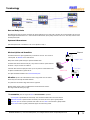
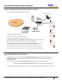

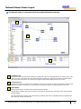

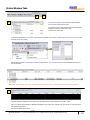
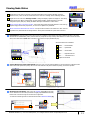


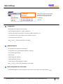
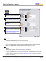
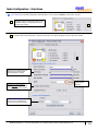

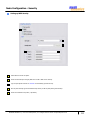

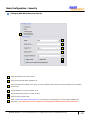
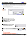

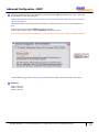

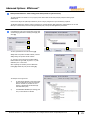
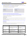

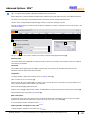
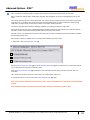

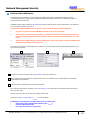

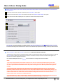
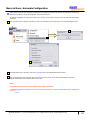

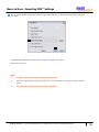
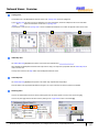
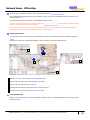
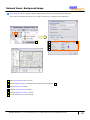


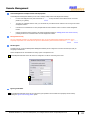

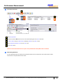
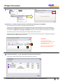
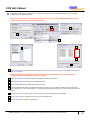
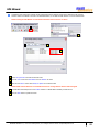

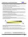
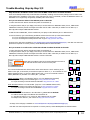


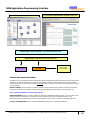


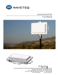
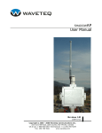

![1 Getting Zabbix [Zabbix]](http://vs1.manualzilla.com/store/data/005748780_1-c6fae7d52ae49b905c6dc80adee0ad61-150x150.png)