1
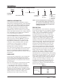
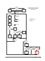
OPERATING INSTRUCTIONS ECONOMIZERS WITH EXHAUST for EQUIPMENT BUILDING APPLICATIONS Model ECONHMT-T5* (Factory Installed Vent Option “F”) with D.B. OUTDOOR CONTROL & ECONHMT-E5* (Factory Installed Vent Option “G”) with ENTHALPY OUTDOOR CONTROL Only for Use with 3½ – 5 Ton H**A/L Series Wall Mount Air Conditioners and the MD4000 Lead-Lag Controller BMC, Inc. Bryan, Ohio 43506 Manual:2100-576A Supersedes:2100-576 File: Volume III Tab 19 Date:09-05-12 Manual2100-576A Page 1 of 10 CONTENTS GENERAL Nomenclature............................................................. 3 General Information................................................... 3 Unpacking.................................................................. 3 Description................................................................. 3 INSTALLATION Intake Air Hood Assembly.......................................... 4 Factory Installed Economizers................................... 4 Field Installed Economizer Hood............................... 4 Enthalpy Settings....................................................... 5 Economizer Features................................................. 6 MV4000 w/AC Units w/DC Control Economizers....... 7 BASIC THEORY of OPERATION Economizer Sequence of Operation.......................... 8 Display & Keypad Operation................................. 8 User Mode............................................................. 8 Engineer Mode...............................................8 - 10 SETUP DC Ampere Current Transmitter.............................. 10 Units Indoor Fan CFM.............................................. 10 Manual2100-576A Page 2 of 10 FIGURES Figure 1 Intake Air Hood.......................................... 4 FigureEnthalpy.................................................... 5 Figure 2 100% Closed Loop Airflow Path................ 6 MV4000 w/AC Units Flow Chart................................ 7 TABLES Table 1 Economizer Application............................. 3 TableEnthalpy.................................................... 5 GENERAL ECONIMIZER WITH EXHAUST MODEL NOMENCLATURE ECON ECONOMIZER H**A/L Series HM T – T 5 X T = Telcom/Equipment Bldg. WALL MOUNT A/C or HP GENERAL INFORMATION The economizer should only be installed by a trained heating and air conditioning technician. These instructions serve as a guide to the technician installing an economizer package, not as a step-by-step procedure with which the mechanically inclined owner can install the package. The economizer installation requires the use of the MD4000 lead-lag controller (if there is not one already present) and requisite amounts of low voltage conductor wire. The number of low-voltage control conductors will vary depending upon application. For H model units with F or G vent option economizers, refer to the MD4000 Series Lead/Lag Controller manual 2100-574 for low voltage connections diagrams. F and G vent option economizers MUST be used with the MD4000 Lead/Lag Controller. No other Lead/ Lag Controller or thermostat is compatible with this economizer. Factory installed F and G vent option economizers are wired per Figure 2 of 2100-574. These economizers CAN NOT be used with the MV4000 Series Lead/Lag Controllers. Any wall mount unit equipped with an economizer must also have a factory/field installed low ambient control. Please refer to appropriate model/year Specification Sheet for requisite field installed low ambient control kit part numbers. UNPACKING Upon receipt of the equipment, be sure to compare the model number found on the shipping label with the accessory identification information on the orders and shipping document to verify that the correct accessory has been shipped. Inspect the carton housing of each economizer assembly as it is received, and before signing the freight bill – verify that all items have been received and there is no visible damage. Note any shortages or damage on all copies of the freight bill. The receiving party must contact the last carrier immediately, preferably in writing, requesting inspection by the carrier’s agent. Concealed damage not discovered until after loading must be reported to the carrier within 15 days of its receipt. T = Temperature E = Enthalpy COLOR OPTIONS X-Beige 1-White 4 - Buckeye Gray 5 - Desert Brown 8 - Dark Bronze CABINET SIZE 5 - 5 Ton (See Table 1) NOTE: Factory installed Telcom economizers have the air intake hood shipped knocked-down. See “Intake Air Hood Assembly” section for shipping location of hood parts and follow the assembly instructions. DESCRIPTION The ECONHMT-T5X, -E5X economizer is designed to be used with wall mount series air conditioners and heat pumps, shown in Table 1, equipped with low ambient controls. They are electromechanical economizer systems designed to provide “free” cooling where the outdoor air temperature/enthalpy is cool enough to provide the needed cooling without running the compressor, or in addition to the compressor. When cooling is required, the system automatically takes advantage of cold outdoor air when available and uses it for first stage cooling. This then reduces the need to run the air conditioning compressor providing lower operating costs and increasing the service life of the equipment. If the outdoor air temperature/enthalpy is too warm to be sufficient for cooling, the dry bulb outdoor air temperature sensor detects the condition and automatically closes the outdoor air intake/exhaust damper, opens the return air damper, and switches to compressor-only operation. Without attention from the end user, the economizer assembly is meant to automatically achieve maximum savings while ensuring appropriately cool space temperatures. The economizer utilizes a fully-modulating damper actuator, which will control intake/exhaust in order to obtain and maintain a factory-set minimum supply air temperature. As a secondary feature, the economizer assembly can be programmed for a minimum ventilation based on an “occupied” (or otherwise dedicated) 24V signal to satisfy fresh air ventilation on populated structures or dilution of internal pollutants. TABLE 1 j MODEL FOR USE WITH FOLLOWING UNITS ECONHMT-T5X -E5X H42A H48A H60A H42L H48L H60L Low ambient control is required w/economizer for low temperature operation and is standard on H-Series units. Manual2100-576A Page 3 of 10 INTAKE AIR HOOD ASSEMBLY The Telcom/Equipment Building version economizers utilize an air intake hood to maximize outdoor airflow performance and to be able to introduce this at low intake velocity. FACTORY INSTALLED ECONOMIZERS The main economizer assembly is installed in the unit’s ventilation cavity, but the air intake hood is shipped knocked down. The intake hood pieces are located on the back side of the A/C unit and inside the front area of the economizer. These will be visible when the temporary shipping panel covering the ventilation cavity is removed and discarded. NOTE: Some applications on equipment buildings necessitate the air intake hood assembly be shipped inside the building for installation at the final site. In this case, the solid panel covering the economizer section must be left in place to protect and weatherize the equipment during transit. FIELD INSTALLED ECONOMIZER HOOD 1. Where discarded Vent Option Panel used to be, install the left and right side of the air hood assembly. Leave the bottom screw out of the right side. (See Figure 1.) 2. With right side of air hood assembly slightly loose and askew, insert the air hood back angle between both sides of the air hood. Move right side into proper position, and insert bottom screw. Attach back angle to both sides of air hood assembly with four (4) screws. (See Figure 1.) 3. Insert rear flange of the top of the air hood assembly behind the bottom of the filter access panel and “hinge” down onto the top of both sides of the air hood assembly. Attach top to sides with four (4) screws. (See Figure 1.) 4. Slide in mist filter through support brackets in sides of air hood assembly. Fine screen should be at the top of the mist filter as it is installed. (See Figure 1.) 5. Attach mist eliminator door to front of air hood. (See Figure 1.) Basic installation and assembly of the economizer hood is now complete. FIGURE 1 3 1 5 2 1 4 SEXP-617 Manual2100-576A Page 4 of 10 ENTHALPY SETTINGS If economizer is dry bulb or enthalpy-based, and was shipped with the appropriate temp/humidity sensor, the economizer must be programmed for the specific enthalpy curve boundary or dry bulb temperature desired for “free” outdoor cooling. The available enthalpy boundaries are all subject to specific OA temperature, OA humidity, and OA dew points. If all of the OA conditions are below the specific points outlined in each boundary, the conditions are good to economize and economizer mode is set to “YES”. If some or all the OA conditions are above the specific points outlined in each boundary, the conditions are not good to economize and the economizer mode is set to “NO”. Point P1 Point P2 Display Setting Enthalpy Curve Temp. Dry Bulb (°F) Temp. Dewpoint (°F) Enthalpy (btu/lb/da) Temp. °F Humidity % RH Temp. °F Humidity % RH 1 ES1 80.0 60.0 28.0 80.0 36.8 66.3 80.1 2 ES2 75.0 57.0 26.0 75.0 39.6 63.3 80.0 3 ES3 70.0 54.0 24.0 70.0 42.3 59.7 81.4 4 ES4 65.0 51.0 22.0 65.0 44.8 55.7 84.2 5 ES5 60.0 48.0 20.0 60.0 46.9 51.3 88.5 0 – 70.0 – – – – – – NOTE: Factory Default Setting is ES3. Manual2100-576A Page 5 of 10 FIGURE 2 100% CLOSED LOOP AIRFLOW PATH COOLING COIL ECONOMIZER FEATURES • One piece construction – easy to install. Direct- drive actuator eliminates linkage. • Exhaust air damper – built in with positive closed position. Provides exhaust air capability to prevent pressurization of tight buildings. SUPPLY AIR • SPYDER™ controller provides nearly limitless customization on a solid, intuitive electronic platform. • AIR FILTER Actuator Motor – 24 volt, power-open, spring- return, direct-coupled with stall protection. Self- centering shaft clamp and access cover facilitate ease of replacement/maintenance. • Proportioning-type control – for maximum “free” cooling economy and comfort with up to 100% outside air. MIST ELIMINATOR 100% RETURN AIR DAMPER BLADE • Dry bulb sensor to monitor outdoor air temperature. • Outdoor Humidity Sensor to monitor outdoor air enthalpy in conjunction with the outdoor air sensor (optional). CONDENSER AIR • Remote display for easy troubleshooting and programming. CONDENSER COIL MIS-2937 • Minimum Ventilation Position available for required ventilation of occupants or dilution of pollutants. • Mixed air sensor to monitor outdoor and return air to automatically modulate damper position. Manual2100-576A Page 6 of 10 MD4000 decides Lead unit Spyder 1 is lead Signals Spyder2 as lag. Is OAT suitable for Cooling MD4000-BCESDC/MD4000-BESDC W/ AC UNITS W/ DC CONTROL ECONOMIZERS Spyder 2 is lead Signals Spyder1 as Lag If OAT <= SP-MTD and Enthalpy is below curve(if equipped No Yes DC Amp load is read and converted to building load with the equation DCA * 106.4-.2455 = BTUH Determine Building Load OAT = Outdoor Air Temperature BL = Building Load MDT = Minimum Temperature Differential RT = Room Temperature SP = Setpoint AC = Available Cooling MAT will be adjusted to take into account deviation from setpoint BL+((RT-SP)*Airflow*1.2) Calculate adjusted building Load (BL) Calculate Available Cooling (AC) for 1 econ Available cooling =( SPMTD-OAT)*1.08*Airflow No Calculate Available cooling for 2 econ If AC > BL Yes No If AC*2 > BL Yes Calculate MAT Start Econ 1 Stop Econ 2 Stop Blower 2 Calculate MAT Start Econ 1 Start Econ 2 Start Blower 2 No Is RT above or below SP Yes Allow econ operation with Compressor Yes Calculate MAT Start Econ 1 Start Econ 2 Start Blower 2 No Stop Econ 1 Stop Econ 2 Stop Blower 2 No Is RT above SP Yes Start Lead Compressor Start Lead Blower Yes No Is RT Below SP Yes Stop Lead Compressor Is 2nd comp Allowed NO Is RT Above ALarn Setpoint No Yes Start Lag Compressor Manual2100-576A Page 7 of 10 BASIC THEORY OF OPERATION These economizers MUST be used with H**A/L model air conditioners and MD4000 Lead/Lag controller. Additionally the shelter must be equipped with a DC amp transmitter that will output a 0-10 volt signal to the MD4000. These economizers monitor outdoor temperature and humidity, mixed air temperature to the coil, and the DC amp draw of the building to determine the building load. The required mixed air temperature to cool the shelter is then determined and the appropriate number of economizers and/or compressors are energized to meet the building load. The control logic resides in the economizers and works in conjunction with the MD4000 Lead lag controller. Access to economizer settings and operational data is done through the remote display and keypad that is mounted on the MD4000 lead lag controller. ECONOMIZER SEQUENCE OF OPERATION (Flow chart on Page 7.) Display and Keypad Operation The display and keypad is used to view current operating parameters, change setpoints, and view current conditions. There are two modes of operation. USER mode displays current operational information and allows temporary override of the setpoint to an occupied setting. ENGINEER mode which allows changes and monitoring of the following sections. Operational data under the USER INFO section, setpoints under the SETPOINT section, economizer setup under the ECON SU section, and load settings under the LOAD SP section. USER Mode User Mode is the default operating mode of the display. On power-up the display will read TR 71 for a few seconds and then the room setpoint, outdoor air temperature and room temperature will be displayed. The display has five (5) keys. Three soft keys whose function is displayed above the key and two (2) arrow keys used to increase or decrease values or settings. On the default screen the Soft keys displayed are OVERIDE and VIEW MORE. Pressing the OVERRIDE soft key will allow overriding the room setpoint to the occupied setpoint for the desired number of hours. Use the up and down arrows to change, DONE to accept the changes or CANCEL to cancel the changes. Once the setpoint is overridden the display will now show that the room is occupied, the current setpoint, the time remaining in the override period. The VIEW MORE soft key displays the following information with each successive key press. No changes can be made to the displayed information. Manual2100-576A Page 8 of 10 RMT - Current room temperature ACT SP - Active room setpoint OAT - Outdoor air temperature OAH - Outdoor humidity MAT - Mixed air temperature to the coil LEAD STS - Lead Status indicates if the unit is the LAG or LEAD unit. FAN STS - Fan status indicated if the fan is ON or OFF. ECO AVL - Economizer availability indicates if the outdoor air is suitable for cooling. YES or NO. ECO CMD - Economizer command indicates that the economizer is ON or OFF. DMPR CMD - Damper command indicates the current position of the damper 0 to 100% open. COMP STS - Compressor Status indicated if the compressor is ON or OFF SD INPUT - Shutdown input indicates if the economizer is closed because the shutdown input is energized. ON or OFF DCT AMP - DC transmitter amp indicates the current DC amp draw of the shelter (0 to 1000 amps). ENGINEER Mode Engineer mode is entered by pressing the UP Arrow, DOWN Arrow, and middle soft key at the same time. Once pressed TR 71 will appear for a few seconds and then the screen will change to the password screen. A password is required for access. The password is 1914. To enter the password use the arrow keys to increment or decrement each blinking digit to the correct number. Use the NEXT soft key to move to the next digit. Once the password is displayed press the DONE soft key to enter the password. The display will now show the room setpoint, outdoor air temperature, and room temperature. Two soft keys will show SET VIEW MORE and PARAMETERS. The SET VIEW MORE soft key allows the engineer to make a property available to the user or not. If the property is yes it is available to the User - if no it is not. Bard does not recommend making any changes to the exposed properties. The PARAMETERS soft key allows the engineer to configure and change setting in five categories. User info Setpoint Econ SU Load SU WM SP Room & Unit operating values. Read only. Room setpoint values. Economizer setpoint values setup. Load calculation values setup. Future use. USER INFO These are read only values and the same values that the user has access to. See previous for descriptions. RMT ACT SP OAT OAH MAT LEAD STS FAN STS ECO AVL ECO CMD DMPR CMD COMP STS SD INPUT DCT AMP SETPOINT RMT SP OCC SP RMT HI SP TEMPOFST DEADBAND Unoccupied setpoint. Default 77. Range 75 - 90 Occupied setpoint. Default 72. Range 70 - 85 High temperature setpoint. Default 80. Range 75 - 90 Room temperature offset. Used to calibrate room temperature. Default 0. Range -10 to +10 Future Use. ECON SU DB ENTH Dry bulb temperature or enthalpy curve for determining if economizer operation is available. If the outdoor temperature is above the room dry bulb temperature or the enthalpy is above the enthalpy curve economizer operation is inhibited. ECONHMT-T5*(F vent option) is a dry bulb only economizer and the value of this must be set to db for proper operation. Default (db). ECONHMT-E5* is an enthalpy economizer and may be set to curves ES1-ES5. See Figure 2 and Table 1 for curve details. Default (ES3). MTD SP Minimum temperature difference setpoint. Economizer operation is allowed if the mixed air temperature is less than the room temperature minus the minimum temperature difference. Default (5 deg.) Range 0-10. MAT LOSP Mixed air temperature Low Setpoint: The lowest mixed air temperature allowed by the economizer to prevent freezing (Default 35) Range 35-55. MIN POS Minimum position of the damper: May be used to provide some continuous ventilation to the structure. Default (0) Range 0 – 100%. DMPR CYL Cycle Damper: Change to 1 to test damper. Damper will cycle full open to full closed. Value will return to 0 when cycle is done. FRZ POS Freeze Position: The position the damper goes to when outdoor temp is below MAT LOSP. Default (0 closed) Range (0-1) 1 (Min. Pos.). EMG VENT Emergency Vent: The position the damper goes to when outdoor temp is below MAT LOSP. Default (0 closed) Range (0-100%). LO T LCK Low Temperature Lock: The temperature below which the compressor will be inhibited from running. Default (0 Deg.) Range (-45 – 80). Manual2100-576A Page 9 of 10 LOAD SU DCT RNGE FAN CFM LOOP TR LOOP INT DV amp transmitter high amp setting Default (500 amps) Range 0-1000 Unit fan CFM Default 1600 See the unit CFM chart in the setup section. PID loop Throttling RangeDefault 2.0 DO NOT change unless instructed to do so by the factory PID loop Integral Time Default 120 DO NOT change unless instructed to do so by the factory Units Indoor Fan CFM WM SP S3DLY HR Future use SETUP The following setting items must be configured via the display and keypad before proper operation of the unit occur. DC Ampere Current Transmitter The DCT RNGE value must be set to the upper limit of the DC ampere current transmitter. If the range is from 0 to 600 amps, set the DCT RNGE to 600. If the range is 0-400 Amps set to 400. Default is 500. Manual2100-576A Page 10 of 10 The FAN CFM value must be set to the airflow the unit is delivering. See the chart below for CFM value for the H model units. A more accurate procedure would be to measure with an airflow hood the air delivered by the unit. MODEL H42A/L H48A/L H60A/L CFM DUCT FREE W/GRILLES High Speed Low Speed Dry Wet Dry Wet 1770 1665 15501500 1770 1665 15501500 2100 1900 15251375 All other settings are pre-set to preferred values and only need changed if desired.