1
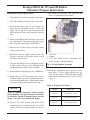
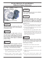
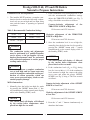
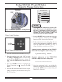
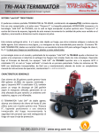
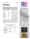
Prestige SOLO 60, 175 and 250 Boilers
Natural to Propane Instructions
Kit Part Number: PSRKIT33
Kit Includes:
- Rating Label
- Conversion Label
- (3) Propane Gas Orifices
- T-25 Torx Wrench
Recommended Tools
-
Standard Adjustable Wrenches
Phillips-Head Screwdriver
Flat-blade Screwdriver
T-40 Torx Wrench
Calibrated Combustion Analyzer
NOTICE
WARNING
Indicates a potentially hazardous situation
which, if ignored, can result in serious
injury or substantial property damage.
Indicates special instructions on installation, operation or maintenance, which are
important to equipment but not related to
personal injury hazards.
NOTICE
WARNING
Failure to follow instructions below can
result in severe personal injury or damage if
ignored.
•
•
•
Upon completion of the conversion from
Natural to Propane, affix the new rating
label included in the kit to the unit adjacent
to the existing rating label. DO NOT affix
the new label over the existing rating label.
Add propane conversion labeling to the gas
valve.
Instructions are for a qualified
installer/service technician.
Read all instructions before proceeding.
Follow instructions in proper order.
NOTICE
WARNING
For your safety, turn off electrical power
supply at service panel before proceeding to
avoid possible electrical shock hazard.
Failure to do so can cause severe personal
injury or death.
These instructions cover NG to LP conversion
for MCBA and Trimax controlled Prestige
boilers. Specific control related instructions
are denoted as (MCBA) or (TRIMAX).
1
Prestige SOLO 60, 175 and 250 Boilers
Natural to Propane Instructions
Installation of the Propane Orifice
the venturi for reference later when the gas
valve is reassembled to the venturi.
1. Turn off the electrical power supply to the boiler.
2. Close the manual gas shut off valve to the unit.
3. Remove the front panel of the Prestige by
removing the mounting screw(s) along the
upper edge of the unit. Lift the panel up and
pull forward to remove the front panel from the
unit.
4. Remove the Phillips head retaining screw from
the control panel. Open the display panel cover
and swing the control panel out (MCBA).
5. Remove the air inlet elbow from the venturi
using a twist motion.
6. Disconnect the gas supply piping inside the
Prestige enclosure at the brass union located
just below the gas valve.
1. Gas Valve
2. Venturi
3. T-25 Torx Head Screws. Attaching Gas
Valve/Venturi to Blower Housing
7. Unscrew the Phillips screw securing the rectifier cable / plug to the gas valve. Disconnect the
rectifier plug from the gas valve (MCBA).
Fig. 1: Prestige Burner Assembly
11. Install the appropriate brass propane orifice
from Table 1 in the gasket between the gas
valve and the venturi. The black rubber gasket
must remain attached to the gas valve. See Fig.
2 page 3.
8. Remove Molex plug from gas valve (TRIMAX).
9. Remove the two T-25 Torx head screws used to
mount the venturi / gas valve assembly to the blower. Do not discard the screws. Dismount the venturi
/ gas valve assembly from the blower. See Fig. 1.
Table 1: Propane Gas Orifice
NOTICE
There is a gasket between the venturi and the
blower housing. This gasket must be reinstallated when the venturi is mounted back onto the
blower. Use care not to damage the gasket.
10. Using a T-25 Torx wrench remove the three
mounting screws attaching the gas valve to the
venturi. Note the orientation of the gas valve to
2
Model
Orifice Size
Solo 60
0.120 inch (3.1 mm)
Solo 175
0.221 inch (5.6 mm)
Solo 250
0.250 inch (6.3 mm)
Prestige SOLO 60, 175 and 250 Boilers
Natural to Propane Instructions
Blower
the blower housing using the two T-25 Torx
head screws.
Install Brass
Gas Valve
Propane Orifice.
Maintain Black Gasket
on Gas Valve
NOTICE
For the reassembly process do not use adhesive
on the venturi / blower gasket.
NOTICE
Use care in the reassembly of the venturi / gas
valve to the blower housing not to cross thread
the mounting screws. Support the weight of the
venturi / gas valve assembly when threading the
mounting screws.
Venturi
Fig. 2:
Venturi/Gas Valve Assembly
NOTICE
14. Reconnect the rectifier plug to the gas valve and
secure using the Phillips head screw (MCBA).
The Solo 60 contains a natural gas orifice. This
orifice must be remove prior to the installation
of the propane orifice.
15. Reconnect Molex plug to the gas valve electrical connection (TRIMAX).
16. Reconnect the brass gas piping union connection and open the manual gas shut off valve.
Before placing the Prestige boiler back into
operation check and test all gas connections for
leaks. Repair leaks if found.
WARNING
Failure to retain the rubber gasket on the gas
valve will cause an improper seal between the
gas valve and the venturi resulting in a potential
risk of a gas leak. Any potential gas leakage may
result in death, serious injury or substantial
property damage.
WARNING
Do not check for gas leaks with an open flame.
Use a bubble test. Failure to check for gas leaks
can cause severe personal injury, death or substantial property damage.
WARNING
Ensure the proper orifice for propane as given in
Table 1. Failure to comply will affect input rate and
combustion of the boiler which may result in death,
serious injury or substantial property damage.
17. Reattach the air inlet elbow to the venturi.
18. Reposition the control panel and reattach the
retaining screw (MCBA).
12. Reassemble the gas valve onto the venturi using
the three T-25 Torx head screws. Ensure the gas
valve is orientated with the venturi correctly.
19. Replace the front jacket panel and secure with
thumb screw.
13. With the venturi / blower gasket in place,
reassemble the venturi / gas valve assembly to
20. Turn on the electrical power supply to the
Prestige boiler and return the unit back to service.
3
Prestige SOLO 60, 175 and 250 Boilers
Natural to Propane Instructions
Combustion Test and Adjustments
2. If the combustion levels during high fire is outside the recommended combustion settings
adjust the THROTTLE SCREW (see Fig. 3)
using a flat-blade screwdriver as follows:
1. The installer MUST perform a complete combustion check to ensure the following combustion levels are met at high and low input firing
rates and the burner is operating at optimum
conditions.
Counter-clockwise adjustment of
THROTTLE SCREW at High Fire:
O2 decreases and CO2 increases
Table 2: Recommended Combustion Settings
02 Min - 2.7%
C02 Min - 10.7%
02 Max - 4.7%
C02 Min - 12.0%
the
Clockwise adjustment of the THROTTLE
SCREW at High Fire:
O2 increases and CO2 decreases
CO Max - 100 ppm
3. Once the combustion level is set at high fire,
manually place the boiler into low fire mode by
pressing the “MODE” button with “-” button
simultaneously on the control display while in
the Standby (STBY) mode.
WARNING
The combustion testing and adjustments
must be performed by a qualified installer,
service agency or the gas supplier. All combustion measurements must be performed
with calibrated equipment to ensure proper
readings and accuracy.
NOTICE
The control panel will display a L followed
by the current boiler temperature when
placed into low fire test mode.
WARNING
4. If the combustion levels (O2 or CO2) during
low fire is not within +/- 0.2 of the combustion
level measured at high fire, remove the offset
cover screw and adjust the plastic OFFSET
SCREW (see Fig 3) using a T-40 Torx wrench
as follows:
Failure to perform a complete combustion
test at both high and low input rates may
result in incomplete combustion and the production of carbon monoxide, which can
cause severe personal injury, death or substantial property damage.
MCBA Instructions
Counter-clockwise adjustment of the OFFSET
SCREW at Low Fire:
1. Manually place the boiler into high fire mode
by pressing the “MODE” button with “+” button simultaneously on the control panel display
while in the Standby (STBY) mode.
O2 increases and CO2 decreases
Clockwise adjustment of the OFFSET SCREW
at Low Fire:
NOTICE
O2 decreases and CO2 increases
The control panel will display a H followed
by the current boiler temperature when
placed into high fire test mode.
5. Press the “+” and “-” buttons simultaneously to
shutdown the burner.
4
Prestige SOLO 60, 175 and 250 Boilers
Natural to Propane Instructions
Offset Pressure
Cover Screw
Manual Operation
Throttle
Screw
FAN
CH
CH1
DHW
SYS
CH2
Released
Off
Off
Off
NOTICE
An adequate CH load must be present to dissipate the heat generated during the combustion test. If an adequate CH load is not available, an indirect water heater can be used to
dissipate the heat by creating a DHW call
which will enable the DHW circulator.
Fig. 3: Combustion Adjustment - Prestige Burner
Trimax Control Procedure
5. Press the RIGHT button to adjust the firing rate
to 100% (high fire). Hold down the RIGHT
button to rapidly increase the firing rate.
6. If the combustion levels during high fire are
outside the recommended combustion settings
adjust the THROTTLE SCREW (see Fig. 3)
using a flat-blade screwdriver as follows:
Installer
Button
Counter-clockwise adjustment of the THROTTLE SCREW at High Fire (100% firing rate):
Fig. 4: Trimax Navigation Buttons
O2 decreases and C02 increases
1. Press the round INSTALLER button. See Fig. 4.
2. Enter the installer access code “054” by using
the LEFT and RIGHT buttons to select a digit
and the UP and DOWN buttons to change the
digit. Press the OK button to enter the access
code.
Clockwise adjustment of the THROTTLE
SCREW at High Fire (100% firing rate):
O2 increases and CO2 decreases
3. Press the RIGHT button to highlight the
Manual Operation icon
then press the OK
button.
7. Once the combustion level is set at high fire,
manually place the boiler into low fire mode by
pressing the LEFT button to adjust firing rate
down to 0% (low fire).
4. Press the OK button while the FAN icon is highlighted to manually fire the burner and power
the CH circulator.
5
Prestige SOLO 60, 175 and 250 Boilers
Natural to Propane Instructions
9. Press the OK button while the fan icon is highlighted to shutdown the burner.
8. If the combustion level (O2 or CO2) during low
fire is not within +/-0.2 of the combustion level
measured at high fire. The offset cover screw
and adjust the plastic OFFSET SCREW (see
Fig. 3) using a T-40 Torx wrench as follows:
10. Press the LEFT or RIGHT button to highlight
the home screen icon
to exit the service
mode.
Counter-clockwise adjustment of OFFSET
SCREW at Low Fire (0% firing rate):
O2 increases and CO2 decreases
Clockwise adjustment of OFFSET SCREW at
Low Fire (0% firing rate):
O2 decreases and CO2 increases
Revised date: 6/5/2012
6
2011-57 Prestige_60,175 and 250 N to LP