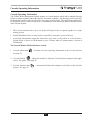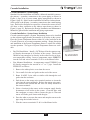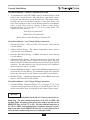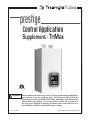
1
prestige
Control Application
Supplement - TriMax
LI
STED
WARNING This document is intended to be used by a factory trained and qualified heating contractor or service technician only. Read all instructions within this
document and within the PRESTIGE Boiler Installation and Maintenance
Manual before proceeding. It is recommended to follow the procedures in
the steps given. Skipping or missing procedural steps could result in severe
personal injury, death or substantial property damage.
Revised 4/20/2012
2012-13 Prestige Trimax Control Appl. Supl.
Table of Contents
Product and Safety Information . . . . . . . . . . . . . . . . . . . . . . . . . . . . . . . . . . 1
Operating Information . . . . . . . . . . . . . . . . . . . . . . . . . . . . . . . . . . . . . . . . . 2
Entering Installer Access Code. . . . . . . . . . . . . . . . . . . . . . . . . . . . . . . . . . . 3
Trimax Installer Menu Structure . . . . . . . . . . . . . . . . . . . . . . . . . . . . . . . . . 4
CH Settings . . . . . . . . . . . . . . . . . . . . . . . . . . . . . . . . . . . . . . . . . . . . . . . . . . 5-13
DHW Settings . . . . . . . . . . . . . . . . . . . . . . . . . . . . . . . . . . . . . . . . . . . . . . . . 14-18
Reset All Settings . . . . . . . . . . . . . . . . . . . . . . . . . . . . . . . . . . . . . . . . . . . . . 19
Factory Trimax Settings . . . . . . . . . . . . . . . . . . . . . . . . . . . . . . . . . . . . . . . . 20
Cascade Operating Information . . . . . . . . . . . . . . . . . . . . . . . . . . . . . . . . . . 21
Trimax Cascade Menu Structure . . . . . . . . . . . . . . . . . . . . . . . . . . . . . . . . . 22
Cascade Installation . . . . . . . . . . . . . . . . . . . . . . . . . . . . . . . . . . . . . . . . . . . 23-31
Cascade Information . . . . . . . . . . . . . . . . . . . . . . . . . . . . . . . . . . . . . . . . . . . 32
Cascade Settings . . . . . . . . . . . . . . . . . . . . . . . . . . . . . . . . . . . . . . . . . . . . . . 33-38
Modbus Interface . . . . . . . . . . . . . . . . . . . . . . . . . . . . . . . . . . . . . . . . . . . . . 39-40
Manual Operation . . . . . . . . . . . . . . . . . . . . . . . . . . . . . . . . . . . . . . . . . . . . . 41
i
Product and Safety Information
IMPoRTanT InfoRMaTIon - REad
BEfoRE PRocEEdInG
WARNING
This document is intended to be used by a factory trained and qualified heating contractor or
service technician only. Read all instructions
within this document and within the PRESTIGE Boiler Installation and Maintenance
Manual before proceeding. It is recommended
to follow the procedures in the steps given.
Skipping or missing procedural steps could
result in severe personal injury, death or substantial property damage.
dEfInITIonS
The following terms are used throughout this
manual to bring attention to the presence of
potential hazards or to important information
concerning the product.
NOTICE
Indicates special instructions on installation,
operation or maintenance, which are important to the equipment but not related to personal injury hazards.
DANGER
Indicates the presence of a hazardous situation which, if ignored, will result in death,
serious injury or substantial property damage.
BEST PRACTICE
Indicates
recommendations made by Triangle
Tube for the installers which will help to
ensure optimum operation and longevity of
the equipment.
WARNING
Indicates a potentially hazardous situation
which, if ignored, can result in death, serious
injury or substantial property damage.
CAUTION
Indicates a potentially hazardous situation
which, if ignored, may result in minor injury
or substantial property damage.
NOTICE
Triangle Tube reserves the right to modify the technical specifications and components of its product without prior notice.
1
operating Information
oPERaTInG InfoRMaTIon
The TriMax Boiler Management System is designed to be flexible yet easy to use. TriMax monitors
and controls the Prestige to operate as efficiently as possible. TriMax monitors the boiler supply,
return and flue gas temperatures and operates the igniter, gas valve and blower. TriMax uses this
information to modulate the boiler’s firing rate to maintain the required setpoint.
TriMax offers many advanced control options, which may be adjusted for various applications to
achieve optimum boiler efficiency and operation.
•
Two central / space heating (CH) call inputs with separate outdoor reset curves.
•
Domestic Hot Water (DHW) call input with optional priority.
•
System temperature sensing and control with an optional system temperature sensor.
•
Cascade function allows up to six Prestige boilers to operate together in a single heating system.
•
Modbus interface for integrating with building management systems.
These advanced features are adjustable in the Installer Menu after entering an access code.
2
Entering Installer access code
EnTERInG InSTaLLER accESS codE
The InSTaLLER button (the small round button) provides the installing contractor with full access
to all available features after entering an access code.
Installer
Button
fig. 1: TriMax navigation Buttons
Entering installer access code procedure
1. Press the round InSTaLLER button.
2. Enter the installer access code “054” by using the LEfT and RIGHT
buttons to select a digit and the UP and doWn buttons to change the
digit. Press the oK button to enter the access code.
3. The Installer Menu will be displayed after successfully entering the
access code. The Home Screen will be displayed if the access code is
not entered correctly.
ENTER INSTALLER
ACCESS CODE
05[4]
NOTICE
Entering the installer access code allows the installer to make adjustments for 30 minutes. after 30 minutes, the access code will need to
be entered again to make any adjustments.
The Installer Menu is divided into four sections:
1. CH & DHW Settings
– Allows the installer to adjust the boilers
central / space heating and domestic hot water settings for the application. See pages 5 through 18.
2. Manual Operation
– The burner and circulators can be manually
enabled for testing. See page 41.
3. Reset All Settings
– Resets all CH, DHW, and Cascade Settings
back to the factory defaults. See pages 19 through 20.
4. Cascade – Settings
Allows the installer to setup, adjust, and monitor the Cascade System. See pages 21 through 38.
3
CH & DHW Settings
Trimax Installer Menu Structure
TriMax Installer Menu Structure
Home Screen
Installer Access Code
ENTER INSTALLER
ACCESS CODE
05[4]
Installer Menu
CH & DHW Settings
CH & DHW Settings Menu
CH Settings
Reset All Settings
Cascade Menu
Reset All Settings
Cascade Information
Manual Operation
Manual Operation
FAN
Press OK button
to restore factory settings,
any other button
to keep current settings
CH
CH1
DHW
SYS
CH2
4
Released
Off
Off
Off
cH Settings
Heating Settings
cH Settings
navigation: Home Screen>Installer Menu>cH & dHW Settings>cH
Settings
The CH Settings menu contains settings related to central heating operation. Each line contains a CH Setting followed by its current value.
Six CH Settings are displayed on the screen at one time. Press the UP
or doWn buttons to scroll through additional CH Settings.
Heating operation
default: Enabled
Heating Operation allows the central heating function to be enabled and
disabled. Press the UP or doWn buttons to select Enabled or Disabled
then press the oK button to store the setting.
•
•
Enabled - The Prestige will respond to a central heating call.
disabled - The Prestige will not respond to a central heating call.
The heating operation disabled icon
is displayed on the home
screen when central heating operation has been disabled.
demand Type
default: Switch & Setpoint
Demand Type allows the installer to select how a CH Demand is generated. Press the UP or doWn buttons to select the CH Demand Type then
press the oK button to store the setting. The CH Demand options are:
•
Switch & outdoor Reset – A central heating call from a dry contact switch will enable the Prestige and the setpoint will vary with
the outdoor temperature for central heating calls
•
Switch & Setpoint - A central heating call from a dry contact
switch will enable the Prestige and the setpoint will be fixed for
central heating calls
•
constant & outdoor Reset - The Prestige will maintain setpoint
and the central heating circulators will be constantly enabled without an external call from a dry contact switch. The central heating
circulators will be disabled when the outdoor temperature exceeds
the Warm Weather Shutdown Temperature setting. The setpoint
will vary with the outdoor temperature for central heating calls.
•
constant & Setpoint - The Prestige will maintain setpoint and the
central heating circulators will be constantly enabled without an
external call from a dry contact switch. The central heating circulators will be disabled when the outdoor temperature exceeds the
Warm Weather Shutdown Temperature setting. The setpoint will be
fixed for central heating calls.
•
0-10V Modulation Signal – This option allows the Prestige firing rate
to be controlled by an external control system with a 0-10 VDC signal.
5
Heating Operation Enabled
Demand Switch & Setpoint
Absolute Max CH Setpoint 194ºF
CH1 Maximum Setpoint 180ºF
CH1 Minimum Setpoint 120ºF
0ºF
Reset Curve Coldest Day
Heating Operation
Disabled
Enabled
Demand Type
Switch & Outdoor Reset
Switch & Set point
Constant & Outdoor Reset
Constant & Setpoint
0-10V Modulation Signal
cH Settings
absolute Max cH Setpoint
default: 194°f [90°c]
Absolute Max CH Setpoint limits the setpoint during a central heating call.
This setting can be used to prevent a user from adjusting the central heating
setpoint or outdoor reset curve above a safe operating temperature in the EZ
Setup Menu. A warning screen will be displayed in EZ Setup if the user
attempts to raise the setpoint above the Absolute Max CH Setpoint. The
Absolute Max CH Setpoint will be displayed on the outdoor reset curve in
EZ Setup if the user selects an outdoor reset curve which goes above the
Absolute Max CH Setpoint. Press the LEfT or RIGHT buttons to adjust
the Absolute Max CH Setpoint then press the oK button to store the setting.
cH1 Maximum Setpoint
default: 180°f [82°c]
CH1 Maximum Setpoint is the maximum setpoint for a CH1 heating call
when an Outdoor Reset option is chosen in CH Demand. CH1 Maximum
Setpoint is the fixed setpoint for a CH1 heating call when a Setpoint option
is chosen in CH Demand. Press the LEfT or RIGHT buttons to adjust
the CH1 Maximum Setpoint then press the oK button to store the setting.
cH1 Minimum Setpoint
default: 120°f [49°c]
CH1 Minimum Setpoint is the minimum setpoint for a CH1 heating call
when an Outdoor Reset option is chosen in CH Demand. This setting is
not applicable when a Setpoint option is chosen in CH Demand. Press the
LEfT or RIGHT buttons to adjust the CH1 Minimum Setpoint then press
the oK button to store the setting.
Reset curve coldest day
default: 0°f [-18°c]
Reset Curve Coldest Day is the coldest outdoor design temperature of the
heating system when an Outdoor Reset option is chosen in CH Demand.
This setting is not applicable when a Setpoint option is chosen in CH
Demand. Press the LEfT or RIGHT buttons to adjust the Reset Curve
Coldest Day then press the oK button to store the setting.
6
Absolute Max
CH Setpoint
194ºF
68ºF
194ºF
CH1 Maximum
Setpoint
180ºF
68ºF
194ºF
CH1 Minimum
Setpoint
120ºF
60ºF
140ºF
Reset Curve
Coldest Day
0ºF
-30ºF
50ºF
cH Settings
Reset curve Warmest day
default: 64°f [18°c]
Reset Curve Warmest Day is the warmest outdoor design temperature of
the heating system when an Outdoor Reset option is chosen in CH
Demand. This setting is not applicable when a Setpoint option is chosen
in CH Demand. Press the LEfT or RIGHT buttons to adjust the Reset
Curve Warmest Day then press the oK button to store the setting.
Reset Curve
Warmest Day
64ºF
60ºF
cH2 circuit
default: Enabled
CH2 Circuit allows the CH2 heating call to be enabled and disabled.
Press the UP or doWn buttons to select Enabled or Disabled then press
the oK button to store the setting.
•
Enabled – The Prestige will respond to a CH2 heating call
•
disabled – The Prestige will not respond to a CH2 heating call
78ºF
CH2 Circuit
Disabled
Enabled
cH2 Maximum Setpoint
default: 140°f [60°c]
CH2 Maximum Setpoint is the maximum setpoint for a CH2 heating call
when an Outdoor Reset option is chosen in CH Demand. CH2
Maximum Setpoint is the fixed setpoint for a CH2 heating call when a
Setpoint option is chosen in CH Demand. Press the LEfT or RIGHT
buttons to adjust the CH2 Maximum Setpoint then press the oK button
to store the setting.
cH2 Minimum Setpoint
default: 80°f [27°c]
CH2 Minimum Setpoint is the minimum setpoint for a CH2 heating
call when an Outdoor Reset option is chosen in CH Demand. This setting is not applicable when a Setpoint option is chosen in CH Demand.
Press the LEfT or RIGHT buttons to adjust the CH2 Minimum
Setpoint then press the oK button to store the setting.
Warm Weather Shutdown
default: off
Warm Weather Shutdown allows the installer to enter an optional outdoor temperature at which to disable the central heating function. The
Prestige will continue to respond to a domestic hot water call or a 010V Modulation Signal when the outdoor temperature exceeds the
Warm Weather Shutdown Temperature setting. Press the LEfT or
RIGHT buttons to adjust the Warm Weather Shutdown Temperature
then press the oK button to store the setting. The Warm Weather
Shutdown icon
is displayed on the home screen when the outdoor
temperature reaches the Warm Weather Shutdown Temperature.
7
Warm Weather Shutdown
Off
Off
78ºF
cH Settings
Pump constant circulation
default: disabled
Pump Constant Circulation allows the central heating circulators to be
constantly enabled even without a central heating call. A domestic hot
water call will cause the circulators to be disabled during the domestic call
as long as DHW Priority is enabled. Press the UP or doWn buttons to
select Enabled or Disabled then press the oK button to store the setting.
•
Pump Constant
Circulation
Disabled
Enabled
Enabled – The central heating circulators will be enabled for constant circulation without a central heating call.
Table 1: circulator operation with Pump circulation = Enabled
•
Prestige Model
CH2 Pump/
System Pump
Auxillary
Boiler Pump
DHW
Pump
CH (1)
Pump
Solo
ON
ON
OFF
ON
Excellence
ON
ON
OFF
OFF
disabled – The central heating circulators will only be enabled during a central heating call.
cH Post Pump Time
default: 1 Minute
CH Post Pump Time sets how long the central heating circulators will
continue to operate at the completion of a heating call. Reference
System Pump in CH Settings on page 10 to determine which circulators
will continue to operate. Any call during the CH Post Pump Time will be
ignored until the post pump has completed. The CH Post Pump feature
allows the heat remaining in the boiler at the completion of a call to be
sent to the heating system, which will improve the overall efficiency of
the system. Press the LEfT or RIGHT buttons to adjust the CH Post
Pump Time then press the oK button to store the setting.
freeze Protection
default: Enabled
Freeze Protection allows the freeze protection feature to be enabled and
disabled. Press the UP or doWn buttons to select Enabled or Disabled
then press the oK button to store the setting.
•
•
Enabled – The Freeze Protection feature is enabled to protect the
boiler from freezing. This feature monitors the boiler water temperature and responds as follows when no call is present:
-
46°F [8°C] – Auxiliary Boiler Pump ON
-
42°F [6°C] – CH(1), Auxiliary Boiler & System Pumps ON.
Burner operates at low fire.
-
60°F [15°C] – Freeze protection ends. Burner & all pumps OFF
after completing CH Post Pump Time.
disabled – The Freeze Protection feature is disabled.
8
CH Post
Pump Time
1 min.
20 min.
Off
Freeze Protection
Disabled
Enabled
cH Settings
WARNING
freeze Protection should only be disabled when the system contains antifreeze to prevent the system from freezing. Serious damage could occur to the Prestige as well as the entire heating system
if freeze Protection is disabled without antifreeze in the system.
WARNING
The Prestige should nEVER be installed in a location where
freezing could occur. Subjecting the Prestige to freezing conditions could lead to freezing of the condensate possibly causing
serious injury or death.
frost Protection Setpoint
default: -22ºf [-30ºc]
Frost Protection will enable the central heating circulators if the outdoor
temperature falls below the Frost Protection Setpoint and no call is present.
This feature requires using the outdoor temperature sensor and is always
active and cannot be disabled. Press the LEfT or RIGHT buttons to adjust
the Frost Protection Setpoint then press the oK button to store the setting.
Frost Protection
Setpoint
-22ºF
-22ºF
50ºF
Table 2: frost Protection circulator operation
Prestige Model
CH2 Pump/
Auxillary
System Pump Boiler Pump
DHW
Pump
CH (1)
Pump
Solo
ON
ON
OFF
ON
Excellence
ON
ON
OFF
OFF
Parallel Shift Value
default: 0°f [0°c]
Parallel Shift allows the CH setpoint to be externally adjusted when a
Constant option is chosen in CH Demand. When a Constant option is chosen in CH Demand, continuous CH1 and CH2 heating calls are generated.
Simultaneous CH1 and CH2 calls will result in the Prestige operating at the
highest CH1 or CH2 setpoint. The CH1 or CH2 Thermostat terminals with
the highest setpoint will be used to adjust the setpoint. If the Thermostat
terminals with the highest setpoint are open, the CH setpoint will decrease
by the Parallel Shift Value. If the Thermostat terminals with the highest
setpoint are closed, the CH setpoint will return to the highest CH1 or CH2
setpoint. Press the LEfT or RIGHT buttons to adjust the Parallel Shift
Value then press the oK button to store the setting.
cH call Blocking
default: 1 Minute
CH Call Blocking sets the minimum time between burner firings for
central heating calls. At the completion of a burner firing, the CH Call
Blocking time will begin. The burner will not fire again until after the
CH Call Blocking time has elapsed. The CH Call Blocking time only
prevents the burner from firing, the central heating circulators will
respond to a central heating call. This blocking time has no affect on
domestic hot water calls. The CH Call Blocking feature prevents short
cycling of the burner and extends the life of the burner components.
Press the LEfT or RIGHT buttons to adjust the CH Call Blocking
time then press the oK button to store the setting.
9
Parallel Shift Value
0ºF
0ºF
144ºF
CH Call Blocking
1 min.
0 min.
30 min.
cH Settings
System Pump
default: cH1/cH2
System Pump allows the system pump operation to be adjusted for the
application. Press the UP or doWn buttons to select the desired System
Pump operation then press the oK button to store the setting. The System
Pump options are:
•
cH1/cH2/dHW – The system pump will be enabled for any CH1,
CH2, or DHW call. Figure 2, page 11 illustrates a typical existing
system requiring this setting.
Table 3: circulator operation with System Pump = cH1/cH2/dHW
•
CH2 Pump/
System Pump
Auxillary
Boiler Pump
CH 1 Call
ON
ON
CH 2 Call
ON
ON
DHW Call
ON
ON
DHW
Pump
OFF
CH (1)
Pump
(Note 1)
OFF
ON
ON
(Note 1)
(Note 1)
ON
OFF
cH1/cH2 – The system pump will only be enabled for a CH1 or
CH2 central heating call. Figure 3, page 12 illustrates a system
zoned with zone valves requiring this setting.
Table 4: circulator operation with System Pump = cH1/cH2
•
CH2 Pump/
System Pump
Auxillary
Boiler Pump
CH (1)
Pump
ON
DHW
Pump
OFF
CH 1 Call
ON
(Note 1)
ON
CH 2 Call
ON
ON
OFF
ON
DHW Call
(Note 1)
OFF
ON
ON
(Note 1)
OFF
cH2 – The system pump will only be enabled for a CH2 central
heating call. The CH(1) pump will only be enabled for a CH1 central heating call. Figure 4, page 13 illustrates a system zoned with
zone circulators requiring this setting.
Table 5: circulator operation with System Pump = cH2
CH2 Pump/
System Pump
Auxillary
Boiler Pump
CH 1 Call
OFF
ON
CH 2 Call
ON
ON
DHW Call
(Note 1)
OFF
ON
DHW
Pump
OFF
CH (1)
Pump
(Note 1)
OFF
OFF
ON
(Note 1)
(Note 1)
ON
OFF
note 1: Domestic Hot Water Priority can be disabled which allows the
CH and DHW circulators to operate at the same time.
NOTICE
The circulator operation shown above only applies when Prestige
Model is set to Solo. System Pump only allows the system pump
operation to be adjusted when Prestige Model is set to Excellence.
10
System Pump
CH1/CH2/DHW
CH1/CH2
CH2
cH Settings
fig. 2: System Piping with System Pump = cH1/cH2/dHW
11
cH Settings
fig. 3: System Piping with System Pump = cH1/cH2
12
cH Settings
fig. 4: System Piping with System Pump = cH2
13
dHW Settings
dHW Settings
DHW Settings
navigation: Home Screen>Installer Menu>cH & dHW
Settings>dHW Settings
The DHW Settings menu contains settings related to domestic hot
water operation. Each line contains a DHW Setting followed by its current value. Six DHW Settings are displayed on the screen at one time.
Press the UP or doWn buttons to scroll through additional DHW
Settings.
dHW operation
default: Enabled
DHW Operation allows the domestic hot water function to be enabled
and disabled. Press the UP or doWn buttons to select Enabled or
Disabled then press the oK button to store the setting.
•
•
Enabled
DHW Operation
Solo
Prestige Model
Switch
Demand
186ºF
Boiler DHW Setpoint
DHW Storage Setpoint 140ºF
6ºF
DHW On Differential
DHW Operation
Disabled
Enabled
Enabled - The Prestige will respond to a domestic hot water call.
disabled - The Prestige will not respond to a domestic hot water
call. The domestic hot water operation disabled icon
is displayed on the home screen when domestic hot water operation has
been disabled.
Prestige Model
PRESTIGE Solo default: Solo
PRESTIGE Excellence default: Excellence
Prestige Model selects how the circulator / diverter valve line voltage terminals will operate. Press the UP or doWn buttons to select Solo or
Excellence then press the oK button to store the setting.
•
•
Solo - The circulator / diverter valve terminals can be used to operate CH(1), DHW, Auxiliary Boiler, and System circulators.
Excellence - The CH(1), DHW, and Auxiliary Boiler circulator /
diverter valve terminals will operate the internal boiler circulator
and diverter valve. Only the System circulator terminals are available for operating a system circulator.
NOTICE
Excellence units also require setting demand Type to Sensor for
correct dHW operation.
14
Prestige Model
Solo
Excellence
dHW Settings
demand Type
PRESTIGE Solo default: Switch
PRESTIGE Excellence default: Sensor
Demand Type allows the installer to select the type of device which will
generate a domestic hot water call. Press the UP or doWn buttons to
select the DHW Demand Type then press the oK button to store the setting. The DHW Demand options are:
•
•
Demand Type
Switch
Sensor
Switch - A domestic hot water call from an aquastat or dry contact
switch will enable the Prestige with a fixed setpoint for a domestic
hot water call.
Sensor - This option requires the use of Indirect Water Heater Sensor
PSRKIT22 which is included with every PRESTIGE Solo. The
PRESTIGE Excellence utilizes an Indirect Water Heater Sensor. The
Prestige will monitor the DHW storage temperature and generate a
domestic hot water call when the temperature drops below the DHW
Storage Setpoint - DHW On Differential.
Boiler dHW Setpoint
default: 186ºf [86ºc]
Boiler DHW Setpoint is the fixed boiler setpoint temperature during a
domestic hot water call when the Switch option is chosen in DHW
Demand. Press the LEfT or RIGHT buttons to adjust the Boiler DHW
Setpoint then press the oK button to store the setting.
dHW Storage Setpoint
default: 140°f [60°c]
DHW Storage Setpoint is the domestic hot water storage setpoint temperature when the Sensor option is chosen in DHW Demand. Press the LEfT
or RIGHT buttons to adjust the DHW Storage Setpoint then press the oK
button to store the setting.
Boiler
DHW Setpoint
186ºF
96ºF
194ºF
DHW
Storage Setpoint
140ºF
68ºF
150ºF
NOTICE
The boiler setpoint is automatically set to the dHW Storage
Setpoint + dHW Storage adder when the Sensor option is chosen in dHW demand.
dHW on differential
default: 6°f [3°c]
DHW On Differential sets how far the DHW storage temperature must fall
below the DHW Storage Setpoint to create a domestic hot water call when
the Sensor option is chosen in DHW Demand. The domestic hot water call
will end when the DHW storage temperature rises above the DHW
Storage Setpoint. Press the LEfT or RIGHT buttons to adjust the DHW
On Differential then press the oK button to store the setting.
15
DHW On Differential
6ºF
4ºF
18ºF
dHW Settings
DANGER
The dHW on differential setting greatly affects the production
of domestic hot water. a low setting could result in a rapid
response to a domestic hot water call resulting in a potential
scald hazard. It is strongly recommended that the installer utilize a thermostatic mixing valve on the hot water outlet of the
Indirect Water Heater. failure to comply could result in severe
personal injury, death, or substantial property damage.
dHW Storage adder
default: 46°f [25°c]
DHW Storage Adder is used to compute the boiler setpoint when the
Sensor option is chosen in DHW Demand. The boiler setpoint will be
DHW Storage Setpoint + DHW Storage Adder for a domestic hot water
call. Press the LEfT or RIGHT buttons to adjust the DHW Storage
Adder then press the oK button to store the setting.
dHW Post Pump Time
default: 1 Minute
DHW Post Pump Time sets how long the domestic hot water circulator
will continue to operate at the completion of a domestic hot water call.
Any call during the DHW Post Pump Time will be ignored until the post
pump has completed. The DHW Post Pump feature allows the heat
remaining in the boiler at the completion of a call to be sent to the
Indirect Water Heater, which will improve the overall efficiency of the
system. Press the LEfT or RIGHT buttons to adjust the DHW Post
Pump Time then press the oK button to store the setting.
dHW Priority Timeout
default: off
DHW Priority Timeout allows the installer to enter an optional time limit
that a domestic hot water call has priority over a central heating call
when DHW Priority is set to Enabled. Press the LEfT or RIGHT buttons to adjust the DHW Priority Timeout then press the oK button to
store the setting.
16
DHW
Storage Adder
46ºF
0ºF
54ºF
DHW Post
Pump Time
1 min.
30 min.
Off
DHW Priority Timeout
Off
Off
60 min.
dHW Settings
DHW Priority
dHW Priority
default: Enabled
DHW Priority allows the domestic hot water priority function to be
enabled and disabled. Press the UP or doWn buttons to select Enabled
or Disabled then press the oK button to store the setting.
•
Enabled- Domestic hot water calls will have priority over a central
heating call. The boiler setpoint will be set to the domestic hot water
setpoint during a domestic hot water call. The DHW circulator will
be enabled and the heating circulators will be disabled during a
domestic hot water call.
•
disabled - Domestic hot water calls will not have priority over a central heating call. The boiler setpoint will be set to the domestic hot
water setpoint when only a domestic hot water call is present. The
boiler setpoint will be set to the highest setpoint when simultaneous
domestic hot water and central heating calls are present. The DHW
circulator will be enabled during a domestic hot water call. The heating circulators will be enabled during a central heating call.
Enabled
Disabled
WARNING
Simultaneous domestic hot water and central heating calls will
result in the PRESTIGE operating at the highest target temperature when dHW Priority is set to disabled. The use of a mixing device on the lower temperature zones such as the Triangle
Tube optima Series SMV control may be required to protect the
lower temperature zones from damage.
NOTICE
dHW Priority should only be set to disabled when Prestige
Model is set to Solo. Setting dHW Priority to disabled when
Prestige Model is set to Excellence will not disable dHW
Priority.
dHW call Blocking
default: 0 Minute
DHW Call Blocking sets the minimum time between burner firings for
domestic hot water calls. At the completion of a burner firing, the DHW
Call Blocking time will begin. The burner will not fire again until after the
DHW Call Blocking time has elapsed. The DHW Call Blocking time only
prevents the burner from firing, the domestic hot water circulator will
respond to a domestic hot water call. This blocking time has no affect on
central heating calls. The DHW Call Blocking feature prevents short
cycling of the burner and extends the life of the burner components. Press
the LEfT or RIGHT buttons to adjust the DHW Call Blocking time then
press the oK button to store the setting.
17
DHW Call
Blocking
0 min.
0 min.
30 min.
dHW Settings
dHW To cH call Blocking
default: 1 Minute
DHW To CH Call Blocking sets the minimum time between a DHW
burner firing and a CH burner firing. At the completion of a DHW burner firing, the DHW to CH Call Blocking time will begin. The burner will
not fire again for a central heating call until after the DHW To CH Call
Blocking time has elapsed. The DHW To CH Call Blocking time only
prevents the burner from firing, the central heating circulators will
respond to a central heating call. This blocking time has no affect on
domestic hot water calls. The DHW To CH Call Blocking feature prevents the burner from firing when switching from a domestic hot water
call to a central heating call. This allows the remaining heat in the heat
exchanger to be dissipated and potentially satisfy the central heating call.
Press the LEfT or RIGHT buttons to adjust the DHW To CH Call
Blocking time then press the oK button to store the setting.
DHW to CH
Call Blocking
1 min.
30 min.
0 min.
Antilegionella Function
antilegionella function
default: disabled
The Antilegionella Function ensures that an Indirect Water Heater is heated at least once per week to prevent the growth of Legionella bacteria.
Press the UP or doWn buttons to select Enabled or Disabled then press
the oK button to store the setting.
•
Enabled- When the Switch option is chosen in DHW Demand, a
domestic hot water call is generated for 15 minutes once per week
to heat the Indirect Water Heater. When the Sensor option is chosen in DHW Demand, a domestic hot water call is generated until
the DHW storage temperature reaches 140°F [60°C] once per
week. When the Sensor option is chosen in DHW Demand, the
weekly timer is reset whenever the DHW storage temperature
reaches 140°F [60°C] to prevent unnecessary firings. This function
will be active even if DHW Operation has been set to Disabled.
•
disabled - The Prestige will only fire in DHW mode when a
domestic hot water call is received.
WARNING
The antilegionella function should only be enabled when an
Indirect Water Heater is installed. Enabling the antilegionella
function without an Indirect Water Heater will result in the
Prestige firing once per week in dHW mode. This could cause
a Manual Reset Hard Lockout resulting in substantial property damage.
BEST PRACTICE
The antilegionella function is most effective when the Sensor
option is chosen in dHW demand. The use of an Indirect
Water Heater Sensor ensures that the domestic hot water is
heated to 140°f [60°c] at least once per week.
18
Enabled
Disabled
Reset all Settings
Reset all Settings
navigation: Home Screen>Installer Menu>Reset all Settings
Reset All Settings allows the installer to reset all CH, DHW, and Cascade
settings back to the original PRESTIGE Solo factory defaults. Follow
the onscreen instructions to reset all settings back to the original factory
defaults
NOTICE
PRESTIGE Excellence units require setting Prestige Model to
Excellence and dHW demand Type to Sensor after using the
Reset all Settings function.
19
Reset All Settings
Press OK button
to restore factory settings,
any other button
to keep current settings.
factory Trimax Settings
factory Trimax Settings
Heating Setting
Heating operation
demand
factory default
Minimum Setting
Maximum Setting EZ Setup Reset Installer Reset
Enabled
Switch & Setpoint
absolute Max cH Setpoint
194°f [90°c]
68°f [20°c]
194°f [90°c]
cH1 Maximum Setpoint
180°f [82°c]
68°f [20°c]
194°f [90°c]
cH1 Minimum Setpoint
120°f [49°c]
60°f [15°c]
140°f [60°c]
Reset curve coldest day
0°f [-18°c]
-30°f [-34°c]
50°f [10°c]
Reset curve Warmest day
64°f [18°c]
60°f [15°c]
78°f [25°c]
cH2 circuit
Enabled
cH2 Maximum Setpoint
140°f [60°c]
68°f [20°c]
194°f [90°c]
cH2 Minimum Setpoint
80°f [27°c]
60°f [15°c]
140°f [60°c]
off
off
78°f [25°c]
off
20 minute
-22°f [-30°c]
-22°f [-30°c]
50°f [10°c]
0°f [0°c]
1 minute
cH1/cH2
0°f [10°c]
0 minute
144°f [80°c]
30 minutes
domestic Setting
factory default
Minimum Setting
dHW operation
Prestige Model
demand
Enabled
Solo
Switch
Warm Weather Shutdown
Pump constant circulation
disabled
cH Post Pump Time
1 minute
freeze Protection
Enabled
frost Protection Setpoint
Parallel Shift Value
cH call Blocking
System Pump
Minimum Setting EZ Setup Reset Installer Reset
Boiler dHW Setpoint
186°f [86°c]
96°f [35°c]
194°f [90°c]
dHW Storage Setpoint
140°f [60°c]
68°f [20°c]
150°f [65°c]
dHW on differential
6°f [3°c]
4°f [2°c]
18°f [10°c]
dHW Storage adder
46°f [25°c]
0°f [0°c]
54°f [30°c]
1 minute
off
30 minutes
off
off
60 minutes
dHW Post Pump Time
dHW Priority Timeout
dHW Priority
Enabled
dHW call Blocking
0 minute
0 minute
30 minutes
dHW to cH call Blocking
1 minute
0 minute
30 minutes
antilegionella function
disabled
cascade Setting
Maximum Setting EZ Setup Reset Installer Reset
factory default
Minimum Setting
60 seconds
30%
398 MBH [117kW]
0
0 second
0%
0 MBH [0kW]
0
255 seconds
100%
869 MBH [255kW]
6
cH Proportional Gain
10
1
255
cH Integral Gain
245
1
255
dHW Proportional Gain
10
1
255
dHW Integral Gain
245
1
255
0=BcST
0
247
Stage delay
Minimum firing Rate
Maximum firing Rate
cH or dHW Boilers
Modbus address
20
cascade operating Information
cascade operating Information
The TriMax Boiler Management System includes a Cascade function which allows multiple Prestige
boilers to operate together without the need for an external controller. One Prestige will be selected as
the Master and will be wired to accept all the low voltage control signals. The other Prestige boilers will
be designated as Slaves and will only have a communication cable connecting them to the other boilers
in the Cascade System.
•
The Cascade function allows up to six identical Prestige boilers to operate together in a single
heating system.
•
Parallel Modulation fires as many boilers as possible to maximize system efficiency.
•
Lead Stage Autorotation rotates the lead boiler every time a call for heat is received when a
Switch option is chosen in CH Demand or every 24 hours when a Constant option is chosen in
CH Demand.
The cascade Menu is divided into three sections
1. Cascade Information
See page 32.
– Provides real time operating information of the Cascade System.
2. Cascade Settings
– Allows the installer to adjust the Cascade System settings for the application. See pages 33 through 38.
3. Cascade Autodetection
System. See page 25.
– Automatically finds and configures each boiler of the Cascade
21
Trimax cascade Menu Structure
Trimax cascade Menu Structure
Installer Menu
Cascade
Cascade Menu
Cascade
Cascade Information Menu
Cascade Information
Cascade Role
System Temp.
Active Boilers
Total Boilers
Cascade Firing Rate
Master
86ºF
0
2
0%
Cascade Settings Menu
Cascade Autodetection
Cascade Settings
Cascade Autodetection
Stage Delay
60 sec
Minimum Firing Rate
30%
Maximum Firing Rate 398 MBH
CH or DHW Boilers
0
CH Proportional Gain
10
CH Integral Gain
245
Press OK Button
to begin Cascade
Autodetection, any
other button to cancel
22
cascade Installation
cascade Installation – System Piping
Standard Cascade installations will utilize a balanced manifold system as
the primary / secondary connection to the system piping as shown in
Figure 6, page 26 or a reverse return piping arrangement as shown in
Figure 8, page 28. Split Cascade installations will utilize a balanced manifold system as the primary / secondary connection to the central heating
loop. Each boiler configured to respond to a domestic hot water call will
also have a direct connection to the indirect water heater as shown in
Figure 10, page 30. Reference the Prestige Installation and Maintenance
Manual for general boiler installation and piping requirements.
cascade Installation – System Sensor Installation
Cascade operation requires a System Temperature Sensor to be installed
on the common supply header downstream of all boilers in the system.
Place the System Temperature Sensor within 10’ of the last boiler in the
Cascade System for an accurate temperature reading. Proper placement
and installation of the System Temperature Sensor is critical for reliable
cascade operation. Two types of System Temperature Sensor are available:
•
•
Dry Well Installation – Install a 3/8”ID drywell in the common supply header downstream of all boilers in the system. The drywell
should be long enough to be directly in the water flow for an accurate temperature reading. Insert a temperature sensor PSRKIT22
into the well and wire to terminals 15 & 16 of the Master boiler.
Pipe Mounted Installation – A temperature sensor PTSENS12 can
be directly strapped to the outside of a 1” to 3” pipe. Install the
PTSENS12 as follows:
1. Remove the white plastic cover from the sensor
2. Cut a small slit in the seal gasket on the end of the sensor.
3. Route 18 AWG 2-wire cable or similar cable through the seal
gasket into the enclosure.
4. Push down on the orange wire terminal retainers to insert the
wires into the sensor terminals. Release the orange wire terminal retainers and confirm that the wires are firmly attached to
the sensor terminals.
5. Select a location for the sensor on the common supply header
downstream of all boilers in the system. Clean the pipe with
fine sandpaper or emery cloth to ensure the pipe is clean and
sensor will make good contact with the pipe.
6. Press the white cover onto the sensor and strap the sensor to the
pipe using the included wire tie.
7. Wire the sensor to terminals 15 & 16 of the Master boiler.
23
Fig. 5: System Sensor
Dry Well Installation
cascade Installation
cascade Installation – cascade communication cable
•
A communication cable PTCAB01 must be installed between each
boiler in the Cascade System. The cable has a 6 pin molex connector on one end and bare wires on the other end. The molex connector plugs into the Cascade Slave connector of the Slave boiler. The
bare wires terminate on the Cascade Master terminals of the Master
boiler or prior Slave boiler in cascades of three or more boilers.
Reference Figure 7,9,11 on pages 27, 29, 31 for wiring details. The
connections are as follows:
Red Wire to Terminal #17
White Wire to Terminal #18
Black Wire & Cable Shielding to Terminal #19
cascade Installation – Low Voltage Wiring connections
•
Thermostat Wiring – CH1 and CH2 calls must be wired into the
Cascade Master.
•
Outdoor Sensor Wiring – The outdoor temperature sensor must be
wired into the Cascade Master.
•
Domestic Hot Water Wiring – A DHW call must be wired into the
Cascade Master.
•
Additional Boiler Limits – Boiler Limits must be wired into each
boiler in the Cascade System. When a boiler limit opens, that particular boiler will lockout and will be removed from Cascade System
operation. The other boilers in the Cascade System will continue to
operate if they are not in a lockout.
•
External Modulation Control – An External Modulation Signal must be
wired into the Cascade Master. The modulation signal will control the
firing rate of the entire Cascade System, not just the Cascade Master.
•
Modbus Wiring – A building management system (BMS) connection
must be wired into the Cascade Master.
cascade Installation – Line Voltage Wiring connections
•
Circulator Wiring - Reference Figures 7,9, 11 on pages 27, 29, 31 for
circulator wiring required for each type of Cascade System. The circulator connections used will depend on the systems piping layout.
NOTICE
Each circulator is individually fused with a 2.5a fuse located in the terminal strip. The total combined amp draw of the cH (1), dHW, and
auxiliary Boiler circulators must not exceed 4 amps at any time for the
PRESTIGE Solo 60, 110, 175, or 250. The total combined amp draw of
the cH (1), dHW, and auxiliary Boiler circulators must not exceed 3
amps at any time for the PRESTIGE Solo 399. Use an isolation relay to
lower the total combined amp draw if exceeding these limits.
24
cascade Installation
•
Power Supply – A dedicated 120 VAC / 15A minimum service must
be used to power the boilers in the Cascade System. Multiple boilers in the Cascade System can be placed on the same electrical circuit. Each boiler can draw a maximum of 8 amps.
•
Alarm Wiring – The alarm contact closes whenever that particular
Prestige is in a soft or hard lockout. The alarm contact will also close
on the Master boiler when any of the Slave boilers are locked out.
cascade Installation – cascade autodetection
navigation: Home Screen>Installer Menu>cascade>cascade
autodetection
The Cascade System must be configured after wiring is completed and
any required adjustments are made in Cascade Settings. The Cascade
Autodetection function automatically finds and configures all boilers in
the Cascade System. This eliminates the need to manually configure
each boiler of the Cascade System. Select Cascade Autodetection on
the Master boiler then follow the onscreen instructions to perform
Cascade Autodetection. Once Cascade Autodetection is finished, a
message will be displayed indicating how many boilers have been
found. If the number of boilers found is correct, press oK to finish
Cascade Autodetection. If the number of boilers found is not correct,
check the cascade communication cables between the boilers and
repeat Cascade Autodetection.
Cascade Autodetection
Press OK button
to begin Cascade
Autodetection, any
other button to cancel
cascade operation – Lockouts
If a lockout occurs to a boiler in a Cascade System, it will be removed
from Cascade System operation. The remainder of the Cascade System
continues to operate and the next available boiler will fire if necessary.
The Lockout Screen will be displayed on the locked out boiler as well as
the Master boiler. The Master boiler Lockout Screen will also indicate
which boiler in the Cascade System is locked out.
Boiler #1
Master
Boiler #2
Slave
Boiler #3
Slave
Failed Ignition
Failed Ignition
The burner failed to light
after 5 ignition attempts.
Check gas supply to boiler.
The burner failed to light
after 5 ignition attempts.
Check gas supply to boiler.
If problem persists after two
reset attempts, call service.
Press OK to reset.
If problem persists after two
reset attempts, call service.
Press OK to reset.
[3] E1
-Slave Operation
E1
The Master boiler indicates
that boiler #3 is locked out
because of failed ignition.
Boiler #3 locked out due
to failed ignition
25
note: Reference Fig. 7, page 27 for cascade wiring.
cascade Installation
fig. 6: Standard Primary Secondary cascade System
26
cascade Installation
note: Reference Fig. 6, page 26 for cascade piping.
fig. 7: Standard Primary Secondary cascade Wiring
27
note: Reference Fig. 9, page 29 for cascade wiring.
cascade Installation
fig. 8: Standard Reverse Return cascade System
28
cascade Installation
note: Reference Fig. 8, page 28 for cascade piping.
fig. 9: Standard Reverse Return cascade Wiring
29
fig. 10: Split cascade System
30
note 2: DHW Priority must be set to Enabled in DHW Settings of the Cascade Master for proper operation.
note 1: Reference Fig. 11, page 31 for cascade wiring.
cascade Installation
cascade Installation
note: Reference Fig. 10, page 30 for cascade piping.
fig. 11: Split cascade Wiring
31
cascade Information
cascade Information
Cascade Information
navigation: Home Screen>Installer Menu>cascade>cascade
Information
Cascade Role
Master
Cascade Information provides real time operating information of the
System Temp.
86ºF
Cascade System. Each line contains an information item followed by its
Active
Boilers
0
current value. See below for a list of all Cascade Information items.
Total Boilers
Cascade Firing Rate
System Temperature Logging
System Temperature has a logging function which records one sample
every 12 minutes to produce a graph of the last 24 hours. Select System
Temperature in Cascade Information then press the oK button to view
the graph.
2
0%
System Temp.
194
68
-24.00
-16.00
-8.00
cascade Information Items
Information Item
Description
Displays the current role of the Prestige in the Cascade System. Cascade
Role will be one of the following:
Cascade Role
System Temperature
•
Master – Indicates this Prestige is the Master boiler in the Cascade
System.
•
Slave – Indicates this Prestige is a Slave boiler in the Cascade System.
•
Standalone – Indicates this Prestige is not part of a Cascade System.
Displays the current system temperature reading on the Master boiler.
If the system sensor is not wired in to the Master boiler, the Master
boiler supply temperature is displayed.
Active Boilers
Displays the current number of boilers fired in the Cascade System.
Total Boilers
Displays the total number of boilers in the Cascade System.
Cascade Firing Rate
Displays the current firing rate of the entire Cascade System.
32
0.00
cascade Settings
Cascade Setting
cascade Settings
navigation: Home Screen>Installer Menu>cascade>cascade
Settings
The Cascade Settings menu contains settings related to cascade operation.
Each line contains a Cascade Setting followed by its current value. Six
Cascade Settings are displayed on the screen at one time. Press the UP
or doWn buttons to scroll through additional Cascade Settings.
Stage Delay
60 sec
Minimum Firing Rate
30%
Maximum Firing Rate 398 MBH
CH or DHW Boilers
0
CH Proportional Gain
10
CH Integral Gain
245
NOTICE
cascade Setting changes must be made on the cascade Master.
cascade autodetection must be performed after making any
changes to a cascade Setting before the change will take effect.
Stage delay
default: 60 Seconds
Stage Delay sets the time delay before enabling or disabling a boiler in the
Cascade System. The Stage Delay begins once the Master boiler determines that
a boiler must be enabled to reach the setpoint or when the Master boiler determines a boiler should be disabled because of a decreasing load. Press the LEfT
or RIGHT buttons to adjust the Stage Delay then press the oK button to store
the setting. Adjusting the Stage Delay will have the following effects:
•
•
Stage Delay
60Sec.
255sec.
0sec.
Increase Stage delay
-
Reaching the setpoint could take longer due to a longer delay
between enabling boilers.
-
Overshooting the setpoint could occur due to boilers staying on
longer before being disabled.
decrease Stage delay
-
Overshooting the setpoint could occur due to boilers being
enabled quicker.
-
Boilers will be disabled quicker, possibly increasing boiler
cycling and decreasing runtimes.
Minimum firing Rate
default: 30%
Minimum Firing Rate is the minimum firing rate of a single boiler in the Cascade
System. The Master boiler uses this setting to determine when boilers can be
enabled and disabled. Setting the Minimum Firing Rate below the recommended minimum will result in boilers being enabled too quickly which may cause
sharp increases in temperature from the Cascade System. Setting the Minimum
Firing Rate above the recommended minimum will delay the enabling of boilers
which may lower the system efficiency. Press the LEfT or RIGHT buttons to
adjust the Minimum Firing Rate then press the oK button to store the setting.
The minimum recommended settings are:
Prestige Model
Solo 60
Solo 110 Natural Gas
Solo 110 Propane Gas
Solo 175
Solo 250
Solo 399
Minimum Firing Rate
28%
29%
27%
31%
28%
30%
33
Minimum Firing Rate
30%
0%
100%
cascade Settings
Boiler Enabling algorithm
The Master boiler uses the following algorithm to determine when the next
boiler can be enabled:
Number of Boilers Firing +1
x Minimum Firing Rate = Individual Boiler Firing Rate
Number of Boilers Firing
Once the currently fired boilers reach the calculated firing rate, the next
boiler can be enabled without affecting the overall cascade firing rate. For
example, the calculation for a Cascade System consisting of two PRESTIGE Solo 399s would be:
1+1
x 30% = 60%
1
Once the first PRESTIGE Solo 399 firing rate reaches 60%, the second
PRESTIGE Solo 399 can be enabled. Both will then fire at the minimum
30% firing rate so that the overall output from the Cascade System remains
the same.
Boiler disabling algorithm
Once the firing rate of all currently fired boilers decreases to the Minimum
Firing Rate, a boiler can be disabled. The boilers which continue to fire
will increase their firing rate if required to replace the output of the disabled boiler.
NOTICE
Stable cascade operation requires that all boilers in a cascade System
be the same size. Mixing boiler sizes in a cascade System could lead
to temperature fluctuations and erratic cascade operation.
Maximum firing Rate
default: 398 MBH
Maximum Firing Rate is the maximum firing rate of a single boiler in the
Cascade System. Press the LEfT or RIGHT buttons to adjust the
Maximum Firing Rate then press the oK button to store the setting. The
recommended settings are:
Prestige Model
Maximum Firing Rate
Solo 60
57 MBH
Solo 110 Natural Gas
109 MBH
Solo 110 Propane Gas
95 MBH
Solo 175
170 MBH
Solo 250
245 MBH
Solo 399
398 MBH
NOTICE
Stable cascade operation requires that all boilers in a cascade System be
the same size. Mixing boiler sizes in a cascade System could lead to temperature fluctuations and erratic cascade operation.
34
Maximum
Firing Rate
398 MBH
0MBH
869MBH
cascade Settings
cH or dHW Boilers
default: 0
The CH or DHW Boilers setting specifies how many boilers in a Split
Cascade System will respond to a domestic hot water call. The CH or
DHW Boilers always include the Master boiler. The remaining boilers
will only respond to central heating calls. This allows the Cascade
System to satisfy both central heating and domestic hot water calls at the
same time. At the completion of a domestic hot water call, the CH or
DHW Boilers will again be available to respond to central heating calls.
Press the LEfT or RIGHT buttons to adjust the CH or DHW Boilers
setting then press the oK button to store the setting.
CH or DHW Boilers
0
6
0
NOTICE
Splitting the cascade System into cH only and cH or dHW boilers
requires the boilers to be piped as shown in figure 10, page 30. The
cH or dHW boilers must be piped to both cH and dHW loads
directly for proper operation.
NOTICE
dHW Priority must be set to Enabled in dHW Settings of the
cascade Master for proper operation.
NOTICE
all cH or dHW Boilers will respond to a domestic hot water call. It
is important that the domestic load is capable of transferring all of
the heat generated to prevent excessive boiler cycling.
cH Proportional Gain
default: 10
CH Proportional Gain allows the cascade response to be adjusted for a
central heating call. CH Proportional Gain has the greatest influence
when the system temperature is far away from the setpoint. Press the
LEfT or RIGHT buttons to adjust the CH Proportional Gain then press
the oK button to store the setting.
•
•
Increase cH Proportional Gain
-
The Cascade System will reach setpoint faster, but overshooting
the setpoint may occur.
-
To reach the setpoint faster, increase the CH Proportional Gain
value by 2. Perform Cascade Autodetection and initiate a central heating call. Observe the cascade response and make further adjustments if necessary.
decrease cH Proportional Gain
-
The Cascade System will take longer to reach the setpoint, but
setpoint overshooting is minimized.
-
If the setpoint is reached too quickly, decrease the CH
Proportional Gain value by 2. Perform Cascade Autodetection
and initiate a central heating call. Observe the cascade response
and make further adjustments if necessary.
35
CH Proportional Gain
10
1
255
cascade Settings
NOTICE
only make adjustments to this setting after consulting Triangle Tube
Technical Support. Improper adjustment of cH Proportional Gain
could lead to temperature fluctuations and erratic cascade operation.
cH Integral Gain
default: 245
CH Integral Gain allows the cascade response to be adjusted for a central
heating call. CH Integral Gain has the greatest influence when the system
temperature is close to the setpoint. Press the LEfT or RIGHT buttons to
adjust the CH Integral Gain then press the oK button to store the setting.
CH Integral Gain
245
255
1
•
•
Increase cH Integral Gain
-
The Cascade System will take longer to reach the setpoint, but
setpoint overshooting is minimized.
-
If the setpoint is reached too quickly, increase the CH Integral
Gain value by 2. Perform Cascade Autodetection and initiate a
central heating call. Observe the cascade response and make further adjustments if necessary.
decrease cH Integral Gain
-
The Cascade System will reach setpoint faster, but overshooting
the setpoint may occur.
-
To reach the setpoint faster, decrease the CH Integral Gain value
by 2. Perform Cascade Autodetection and initiate a central heating call. Observe the cascade response and make further adjustments if necessary.
NOTICE
only make adjustments to this setting after consulting Triangle Tube
Technical Support. Improper adjustment of cH Integral Gain could
lead to temperature fluctuations and erratic cascade operation.
dHW Proportional Gain
default: 10
DHW Proportional Gain allows the cascade response to be adjusted for a
domestic hot water call. DHW Proportional Gain has the greatest influence when the system temperature is far away from the setpoint. Press the
LEfT or RIGHT buttons to adjust the DHW Proportional Gain then press
the oK button to store the setting.
•
Increase dHW Proportional Gain
-
The Cascade System will reach setpoint faster, but overshooting
the setpoint may occur.
36
DHW Proportional Gain
10
1
255
cascade Settings
-
•
To reach the setpoint faster, increase the DHW Proportional
Gain value by 2. Perform Cascade Autodetection and initiate a
domestic hot water call. Observe the cascade response and
make further adjustments if necessary.
decrease dHW Proportional Gain
-
The Cascade System will take longer to reach the setpoint, but
setpoint overshooting is minimized.
-
If the setpoint is reached too quickly, decrease the DHW
Proportional Gain value by 2. Perform Cascade Autodetection
and initiate a domestic hot water call. Observe the cascade
response and make further adjustments if necessary.
NOTICE
only make adjustments to this setting after consulting Triangle Tube
Technical Support. Improper adjustment of dHW Proportional
Gain could lead to temperature fluctuations and erratic cascade
operation.
dHW Integral Gain
default: 245
DHW Integral Gain allows the cascade response to be adjusted for a
domestic hot water call. DHW Integral Gain has the greatest influence
when the system temperature is close to the setpoint. Press the LEfT or
RIGHT buttons to adjust the DHW Integral Gain then press the oK button to store the setting.
•
•
Increase dHW Integral Gain
-
The Cascade System will take longer to reach the setpoint, but
setpoint overshooting is minimized.
-
If the setpoint is reached too quickly, increase the DHW Integral
Gain value by 2. Perform Cascade Autodetection and initiate a
domestic hot water call. Observe the cascade response and
make further adjustments if necessary.
decrease dHW Integral Gain
-
The Cascade System will reach setpoint faster, but overshooting
the setpoint may occur.
-
To reach the setpoint faster, decrease the DHW Integral Gain
value by 2. Perform Cascade Autodetection and initiate a
domestic hot water call. Observe the cascade response and
make further adjustments if necessary.
37
DHW Integral Gain
245
1
255
cascade Settings
NOTICE
only make adjustments to this setting after consulting Triangle Tube
Technical Support. Improper adjustment of dHW Integral Gain
could lead to temperature fluctuations and erratic cascade operation.
Modbus address
default:0=BcST
Modbus Address assigns the boiler with a unique address in the Modbus
control system. Press the LEfT or RIGHT buttons to change the Modbus
Address then press the oK button to store the setting.
Modbus Address
0=BCST
0=BCST
38
247
Modbus Interface
Modbus Interface
The Modbus Interface allows a Building Management System (BMS) to directly connect to the Prestige.
A BMS can read information from the boiler to determine its operating state, lockout status, sensor readings, etc. A BMS can also operate the boiler by providing a setpoint.
Table 6: Modbus Configuration
Protocol
MODBUS RTU
Baud Rate
38400bps
Data Length
8
Parity
None
Stop Bits
1
Physical Layer
RS485 (2 wire)
Table 7: Supported Commands
DEC
HEX
Description
03
0x03
Read Holding Registers
04
0x04
Read Input Registers
06
0x06
Write Single Register
16
0x10
Write Multiple Registers
17
0x11
Report Slave ID
Table 8: Holding Registers (Read/Write)
Address
DEC (HEX)
Supported
Commands
512 (0x0200)
0x03
0x06
0x10
Description
Byte: Format
Notes
CH Demand
MB:U8
Writing
0= Modbus CH1 Demand has priority
over a DHW call
255 = DHW call has priority over a
Modbus CH1 Demand
LB:U8
Reading
0 = No CH Calls Present
255 = CH1 or CH2 Call Present
Writing
0 = End CH1 Demand
255= Begin CH1 Demand
A CH1 Demand lasts for 30 seconds
from the last successful write.
513 (0x201)
0x03
0x06
0x10
Maximum Firing Rate
LB:U8
Value = Maximum Firing Rate %
This register becomes active when 255
is written to register 512 (0x0200)
514 (0x202)
0x03
0x06
0x10
CH Setpoint
LB:U8
Value = CH Setpoint °C
This register becomes active when 255
is written to register 512 (0x0200)
1280 (0x0500)
0x03
CH1 Maximum
Setpoint
LB:U8
Value = °C
1281 (0x0501)
0x03
DHW Storage Setpoint
LB:U8
Value = °C
39
Modbus Interface
Table 9: Input Registers (Read only)
Address
DEC (HEX)
0 (0x0000)
Supported
Commands
0x04
Description
Byte: Format
Boiler Status
LB: Flag8
Bit: Description
0: PC Manual Mode
1: DHW Mode
2: CH Mode
3: Freeze Protection Mode
4: Flame Present
5: CH(1) Pump
6: DHW Pump
7: System / CH2 Pump
0 = Off, 1 = On
1 (0x0001)
0x04
Lockout Status
MB: Flag8
Bit: Description
1: Lockout Code Type
0 = Automatic Reset Lockout
1 = Manual Reset Lockout
Notes
LB:U8
Value = Lockout Code
0 = Single / Master Boiler
1 = Slave 1
2 = Slave 2
3 = Slave 3
4 = Slave 4
5 = Slave 5
F = Single / Master Display
2 (0x0002)
0x04
Lockout Status
LB:U8
768 (0x0300)
0x04
Boiler Supply
Temperature /
System Temperature
S16
Value = 0.1°C
Invalid Value = 32768 (0x8000)
Value is the Boiler Supply
Temperature unless the System
Temperature Sensor is installed
769 (0x0301)
0x04
LB:S8
770 (0x0302)
0x04
771 (0x0303)
0x04
772 (0x0304)
0x04
Boiler Return
Temperature
DHW Storage
Temperature
Boiler Flue
Temperature
Outdoor Temperature
Value = °C
Invalid Value = 65472 (0xFFC0)
Value = °C
Invalid Value = 32768 (0x8000)
Value = °C
Invalid Value = 65472 (0xFFC0)
Value = °C
Invalid Value = 32768 (0x8000)
773 (0x0305)
0x04
Future Use
LB:U8
774 (0x0306)
0x04
LB:U8
Value = Flame Current µA
775 (0x0307)
0x04
LB:U8
Value = Firing Rate %
776 (0x0308)
0x04
Flame Ionization
Current
Boiler / Cascade
Firing Rate
Boiler Setpoint
LB:U8
Value = °C
Invalid Value = 32768 (0x8000)
40
LB:S8
LB:S8
LB:S8
Manual operation
Manual operation
navigation: Home Screen>Installer Menu>Manual operation
The Manual Operation Screen allows the burner and circulators to be manually enabled for testing.
fan
Press the oK button while the FAN icon is highlighted to manually fire
the burner and power the CH (1) circulator. Press the LEfT and
RIGHT buttons to adjust the firing rate from 0% (Low Fire) to
100% (High Fire). Hold down the LEfT or RIGHT buttons to rapidly
increase or decrease the firing rate. Press the oK button again while the
FAN icon is highlighted to shutdown the burner when finished.
Manual Operation
FAN
CH
CH1
DHW
SYS
CH2
Released
Off
Off
Off
NOTICE
an adequate cH load must be present to dissipate the heat generated
while the burner is manually fired. If an adequate cH load is not available, an indirect water heater can be used to dissipate the heat by creating a domestic hot water call which will enable the dHW circulator.
cH cH1
Press the oK button while the CH CH1 icon is highlighted to manually
power the CH (1) circulator. Press the oK button again while the CH
CH1 icon is highlighted to shutdown the CH (1) circulator.
Manual Operation
FAN
CH
CH1
DHW
SYS
CH2
Released
Off
Off
Off
NOTICE
The auxiliary Boiler circulator is also powered when the cH (1) circulator is manually enabled.
dHW
Press the oK button while the DHW icon is highlighted to manually
power the DHW circulator. Press the oK button again while the DHW
icon is highlighted to shutdown the DHW circulator.
Manual Operation
FAN
CH
CH1
DHW
SYS
CH2
Released
Off
Off
Off
NOTICE
The auxiliary Boiler circulator is also powered when the dHW circulator is manually enabled.
SYS cH2
Press the oK button while the SYS CH2 icon is highlighted to manually
power the System circulator. Press the oK button again while the SYS
CH2 icon is highlighted to shutdown the System circulator.
Manual Operation
FAN
CH
CH1
DHW
SYS
CH2
41
Released
Off
Off
Off
Additional quality water heating equipment available from
Triangle Tube/Phase III
MAXI-FLO AND SPA HEAT EXCHANGERS
-
Construction of high quality corrosion resistant stainless
steel (AISI 316) or titanium
-
Specially designed built-in flow restrictor to assure maximum heat exchange
-
Compact and light weight
-
Available in 5 sizes that can accommodate any size pool
or spa
SMART INDIRECT FIRED WATER HEATERS
-
Exclusive tank-in-tank design
-
Stainless steel construction
-
Available in 8 sizes
-
Limited LIFETIME residential warranty
-
6 year commercial warranty
-
Self cleaning/self descaling design
TTP BRAzED PLATE HEAT EXCHANGERS
-
For domestic water, snow melting, radiant floor, refrigeration
-
Plates made of stainless steel, with a 99.9 % copper and
brazed, ensuring a high resistance to corrosion
-
Self cleaning and self descaling
-
Computerized sizing available from Triangle Tube
-
Available in capacities from 25,000 BTU/hr to 5,000,000
BTU/hr
1 Triangle Lane - Blackwood, NJ 08012
Tel: (856) 228 8881 - Fax: (856) 228 3584
E-mail: [email protected]