1
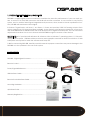
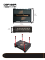
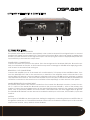
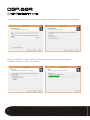
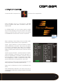
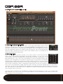
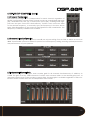
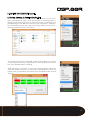
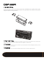
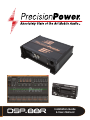
Installation Guide
& Users Manual
1
Index
1. PRODUCT DESCRIPTION & WARNINGS3
2. CONTENTS3
3. DIMENSIONS & MOUNTING
4
4. PRIMARY WIRE HARNESS & CONNECTIONS 4.1 Primary Wire Harness5-6
4.2 Input Gain Control7
4.3 RCA Auxiliary Input7
4.4 SPDIF / Optical Input7
4.5 Remote Control Connecition7
4.6 USB Connection7
4.7 RCA Outputs7
5. SOFTWARE INSTALLATION8-10
6. DSP-88R DSP COMPOSER 11
6.1 Channel Summing & Input Mode12
6.2 Channel Setting12
6.3 Crossover Configuration13
6.4 Crossover Slope Configuration13
6.5 Independent Channel Gain13
6.6 Independent Channel Delay14
6.7 Response Graph14
6.8 Equalizer Adjustments14
6.9 Saving, Opening, & Downloading Pre-Sets
15
7. REMOTE CONTROL 7.1 Master Volume Control16
7.2 Preset Selection16
7.3 Input Selection16
8. SPECIFICATIONS17
2
1. PRODUCT DESCRIPTION & WARNINGS
DSP-88R is a digital signal processor essential to maximize the acoustic performance of your car audio system. It consists of a 32-bit DSP processor and 24-bit AD and DA converters. It can connect to any factory
system, even in vehicles featuring an integrated audio processor, since, thanks to the de-equalization function, DSP-88R will send back a linear signal.
It features 7 signal inputs: 4 Hi-Level, 1 Aux Stereo, 1 Phone and provides 5 PRE OUT analog outputs. Each
output channel has a 31-band equalizer available. It also features a 66-frequency electronic crossover as
well as BUTTERWORTH or LINKWITZ filters with 6-24 dB slopes and a digital time delay line. The user can select
adjustments that allow him or her to interact with DSP-88R through the remote control device.
WARNING: A PC provided with Windows XP, Windows Vista or Windows 7 operating system, 1.5 GHz mini-
mum processor speed, 1 GB RAM minimum memory and a graphics card with a minimum resolution of 1024
x 600 pixels are required to install the software and setup the.
2- Before connecting DSP-88R, carefully read this manual. Improper connections may cause damage to the
DSP-88R or to the speakers in the car audio system.
2. CONTENTS
DSP-88R - Digital Signal Processor.......................................................................
Remote Control...............................................................
Power / Signal Wire Harness...................................................................................
USB Interface Cable.........................................................
Remote Control Interface Cable..........................................................................
Mounting Hardware.........................................................
Quick Start Guide..................................................................................................
Warranty Registration.......................................................
3
3. DIMENSIONS & MOUNTING
5 3/8”
135mm
6 3/4”
172mm
1 7/8”
47mm
4
4. PRIMARY WIRE HARNESS & CONNECTIONS
1
2
3
4
5
4.1 Primary Wire Harness
HIGH LEVEL / SPEAKER LEVEL INPUTS
The primary wire harness includes appropriately color-coded 4-channel hi-level signal inputs to connect
speaker level signal from the head unit. If the head unit low-level RCA outputs are equal or greater than
2V RMS, you can connect it to the high-level inputs. Use the input gain control to appropriately match the
input sensitivity to the head unit output level.
POWER SUPPLY CONNECTIONS
Connect constant 12V+ power to the yellow 12V+ wire and ground to the black GND wire. Be sure the polarity is as indicated on the wire. A misconnection may result in damage to DSP-88R. After applying power,
wait at least 10 seconds before turning on.
REMOTE IN / OUT CONNECTIONS
Connect the amplifier turn-on of the head unit or switched/ACC 12V power to the red REM IN wires. Connect the blue REM OUT wire to the remote turn-on terminal of the amplifier and/or other devices in the
system. REM OUT features a 2 second delay to eliminate noise pops. DSP-88R must be switched on before
any amplifiers are turned on. The head units amplifier turn-on must be connected to REM IN, and REM OUT
should be connected to the remote turn-on terminal of the amplifier(s) or other devices in the system.
HANDS-FREE BLUETOOTH MODULE INPUT
The primary wire harness also features connections for a hands free Bluetooth module. Connect the audio +/- outputs of the hands-free Bluetooth module to the pink color PHONE +/- wires of the primary wire
harness. Connect the mute trigger output of the hands-free Bluetooth module to the orange color PHONE
MUTE - wire of the primary harness. The mute control is activated when the mute trigger receives ground.
The PHONE MUTE terminal can also be used to enable the AUX input. In this case, the PHONE +/- inputs are
inactive.
MUTE IN
The outputs of DSP-88R can be muted when starting the engine by connecting the brown MUTE IN wire to
the ignition starter turn-on. The MUTE IN terminal can be used to enable the AUX IN input. In this case the
output mute function, set by default, will be disabled.
5
4. PRIMARY WIRE HARNESS & CONNECTIONS (cont.)
MUTE TRIGGER (BROWN) 1
REMOTE OUT (BLUE) 2
N/A 3
RREMOTE IN (RED) 4
N/A 5
PHONE - (PINK/BLK) 6
REAR LEFT - (GREEN/BLK) 7
REAR RIGHT - (PURPLE/BLK) 8
FRONT LEFT WHITE/BLK) 9
FRONT RIGHT - (GREY/BLK) 10
11
12
13
14
15
16
17
18
19
20
GROUND (BLACK)
N/A
+12V (YELLOW)
REMOTE IN (RED)
PHONE MUTE (ORANGE)
PHONE + (PINK)
REAR LEFT + (GREEN)
REAR RIGHT + (PURPLE)
FRONT LEFT + (WHITE)
FRONT RIGHT + (GREY)
1
BROWN
MUTE TRIGGER
2
BLUE
REMOTE OUT
3
N/A
4
RED
5
N/A
6
PINK/BLK
PHONE -
7
GREEN/BLK
REAR LEFT -
8
PURPLE/BLK
REAR RIGHT -
9
WHITE/BLK
FRONT LEFT -
REMOTE IN
10 GREY/BLK
FRONT RIGHT -
11 BLACK
GROUND
12 N/A
6
13 YELLOW
+12V
14 RED
REMOTE IN
15 ORANGE
PHONE MUTE
16 PINK
PHONE +
17 GREEN
REAR LEFT +
18 PURPLE
REAR RIGHT +
19 WHITE
FRONT LEFT +
20 GREY
FRONT RIGHT +
4. PRIMARY WIRE HARNESS & CONNECTIONS (cont.)
4.2 Input Gain Control
Use the input gain control to appropriately match the input sensitivity to the head unit output level.
High-level input sensitivity is adjustable from 2v-15V.
AUX/low level input sensitivity is adjustable from 200mV-5V.
4.3 RCA Auxiliary Input
DSP-88R features an auxiliary stereo signal input to connect to an external source such as mp3 player
or other audio sources. The AUX input can be selected by the remote control or activating the brown
MUTE-IN wire.
4.4 SPDIF / Optical Input
Connect the optical output of the head unit or audio device to the SPDIF/Optical audio input. When the
optical input is used, the high level inputs are bypassed.
4.5 Remote Control Connecition
Connect the remote control module to the remote control input, using the supplied network cable. See
section 7 for use of the remote control.
6
7
4.6 USB Connection
Connect DSP-88R to a PC and manage its functions via the supplied USB cable. The connection standard is USB 1.1 / 2.0 compatible.
4.7 RCA Outputs
Connect the RCA outputs of DSP-88R to the corresponding amplifiers, as determined by the settings of
the DSP software.
7
5. SOFTWARE INSTALLATION
Visit SOUNDSTREAM.COM to download the latest version of the DSP Composer software and USB drivers to
your PC. Be sure to download USB drivers for your computers operating system, Windows 7/8 or XP:
After downloading, first install the USB drivers by launching SETUP.EXE in the USB folder. Click INSTALL to complete installation of the USB drivers:
After successful installation of the USB drivers,
launch the DSP Composer setup application. Select
your preferred language:
8
5. SOFTWARE INSTALLATION (cont.)
Close any open applications and click NEXT:
Review the license agreement &
select I ACCEPT THE AGREEMENT, and
click NEXT:
Choose an alternate location to save
the program files, or click NEXT to confirm the default location:
9
5. SOFTWARE INSTALLATION (cont.)
Choose to install a short cut in the start menu or create a desktop and QuickLaunch icons, click NEXT:
Finally, click INSTALL to begin installation of the DSP Composer software. If prompted after
installation completion, restart your computer:
10
6. DSP-88R DSP COMPOSER
Locate the DSP Composer icon
and launch the application:
Select DSP-88R if the PC is connected to DSP-88R
via the supplied USB cable, otherwise select OFFLINE-MODE.
In OFFLINE-MODE, you can create and/or modify
new and pre-existing custom user presets. No modifications to the DSP will be saved until you reconnect
to DSP-88R and download the custom user preset.
When creating a new setting, chose the EQ combination that is appropriate for your application:
Option 1 gives channels 1-6 (A-F) 31-bands of equalization (20-20kHz). Channels 7 & 8 (G & H) are given
11 bands of equalization (20-150Hz). This configuration is optimal for typical 2-way component or bi-ampable coaxial systems where active crossovers will be
utilized.
Option 2 gives channels 1-4 (A-D) 31-bands of equalization (20-20kHz). Channels 5 & 6 (E & F) are given 11
bands of equalization, (65-16kHz). Channels 7 & 8 (G
& H) are given 11 bands of equalization (20-150Hz).
This configuration is ideal for advanced 3-way component applications using all active crossovers.
Other options include units of measurement for time
delay adjustment, and READ FROM DEVICE.
Select MS for millisecond or CM for centimeter time
delay.
Select READ FROM DEVICE for the DSP Composer to
read the EQ combination settings currently uploaded
to DSP-88R.
11
6. DSP-88R DSP COMPOSER (cont.)
9
1
2
3
5
6
4
4
7
8
6.1 Channel Summing & Input Mode
For input summing options, in the FILE menu, chose CD SOURCE SETUP. Select which
channels are high-pass or low-pass by selecting TWEETER or MIDRANGE for the appropriate input channel, otherwise keep FULLRANGE. Chose the signal input mode
you are creating this preset for. SPDIF for the optical input, CD for the primary wire
harnesses high / speaker level input, AUX for the AUX RCA input, or PHONE for the
hands-free Bluetooth module input.
6.2 Channel Setting
Select the channel 1-8 (A-H) to modify. If you chose option 1 from the EQ combination menu, equalization adjustments for the left channels (1, 3, & 5 / A, C & E)
are matched. Crossover settings remain independent. Likewise, equalization for the
right channels (2, 4, & 6 / B, D, & F) are matched. Crossover settings remain independent. This configuration is optimal for typical 2-way component or bi-ampable
coaxial systems where active crossovers will be utilized. Channels 7 & 8 (G & H) are
independently variable equalization and crossover settings. If you chose option 2
from the EQ combination menu, equalization adjustments for the left channels (1
& 3 / A & C) are matched, as right channels (2 & 4 / B & D). Crossover settings remain independent.
Channels 5 & 6 (E & F) are independently variable for equalization and crossover settings, as are channels 7 & 8 (G & H) for subwoofers. This configuration is ideal for advanced 3-way component applications using all active crossovers.
Use A>B COPY to duplicate the equalization settings of the left channels, (1, 3, & 5 / A, C, & E) for the
right channels, (2, 4, & 6 / B, D, & F). The right channels can be modified further after an A>B COPY
without effect to the left channels.
12
6. DSP-88R DSP COMPOSER (cont.)
6.3 Crossover Configuration
The crossover configuration is independent for each channel, regardless of
the EQ configuration chosen. Each channel could use a dedicated high-pass
(HP), dedicated low-pass (LP), or band-pass option (BP), enabling both highpass and low-pass crossovers simultaneously. Position each crossover slider
to the desired frequency, or manually type the frequency in the box above
each slider. Regardless of the crossover configuration or EQ combination, the
frequency is infinitely variable from 20-20kHz.
6.4 Crossover Slope Configuration
Each crossover setting can be given its own dB per octave setting, from as little as 6dB to as much as
48dB. These flexible crossovers allows for precise cut-off frequency setting, ensuring optimal protection
and performance of your speakers.
6.5 Independent Channel Gain
Each channel is give -40dB gain, and a master gain for all channels simultaneously of -40dB up to
+12dB. The gain is set by .5dB increments. Position each channel slider to the desired gain level, or
manually type the level in the box above each slider. Channel gain is available regardless of EQ combination. Each channel also has an independent mute switch.
13
6. DSP-88R DSP COMPOSER (cont.)
6.6 Independent Channel Delay
A specific digital time delay can be applied to each channel. Depending on your choice at the EQ
combination menu, the unit of measure is milliseconds or centimeters. If you chose millimeters, the
delay is set in .05ms increments. If you chose centimeters, the delay is set in 2cm increments. Position
each channel slider to the desired delay level, or manually type the level in the box above each slider.
Also, each channel has a 180 0 phase switch below each slider.
6.7 Response Graph
The response graph shows the response for each channel with the modifications given to it, including crossover and all bands of equalization, with reference to 0dB. The crossover frequencies can be
manually adjusted by clicking the blue position for low-pass, or red position for high-pass and dragging
to the desired location. The graph will show each channels projected response when the channel is
selected from the channel setting.
6.8 Equalizer Adjustments
Available frequency bands for the selected channel will appear. If option 1 was chosen for the EQ
combination, channels 1-6 (A-F) will have 31 1/3 octave bands, 20-20kHz. Channels 7 & 8 will have
11-bands, 20-200 Hz. If option 2 was chosen, channels 1-4 (A-D) will have 31 1/3 octave bands, 2020kHz. Channels 5 & 6 (E & F) will have 11-bands, 63-16kHz. Channels 7 & 8 (G & H) will have 11 bands,
20-200Hz.
14
6. DSP-88R DSP COMPOSER (cont.)
6.9 Saving, Opening, & Downloading Pre-Sets
While using DSP-88R DSP Composer in off-line mode, you can create a new preset or open, view and modify an existing preset. If
making a new preset, be sure to save the preset for recalling and
downloading to DSP-88R the next time your computer is connected. Click FILE from the menu bar, and chose SAVE. Chose a convenient location to save your preset.
To download a preset to DSP-88R, either after making your preset
or opening a previously created preset, select FILE from the menu
bar, then DOWNLOAD TO DEVICE.
After choosing a location to save your preset again, select an
available preset position to download to DSP-88R. Click SAVE TO
FLASH. Now your preset(s) are ready to be recalled by the remote
control.
15
7. REMOTE CONTROL
Connect the remote control to the remote control input of DSP-88R by the supplied network cable.
Mount the remote control in a convenient location in the main cabin of the vehicle for easy access
using the supplied mounting hardware.
1
2
3
7.1 Master Volume Control
The master volume knob can be used as an auxiliary volume control, the maximum is 40. A quick press
of the button will mute all output. Depress the button again to cancel mute.
7.2 Preset Selection
Press the up or down arrow buttons to scroll thru your saved presets. After locating the preset you wish
to activate, press the OK button.
7.3 Input Selection
Press the INPUT buttons to activate the different inputs from your various audio devices.
16
8. SPECIFICATIONS
Power Supply
Voltage 11-15 VDC
Idle Current 0.4 A
Switched Off without DRC 2.5 mA
Switched Off with DRC 4 mA
Remote IN Voltage 7-15 VDC (1.3 mA)
Remote OUT Voltage 12 VDC (130 mA)
Signal Stage
Distortion - THD @ 1kHz, 1V RMS Output 0.005 %
Bandwidth @ -3 dB 10-22k Hz
S/N ratio @ A weighted
Master Input 95 dBA
Aux Input 96 dBA
Channel Separation @ 1 kHz 88 dB
Input Sensitivity (Speaker In) 2-15V RMS
Input Sensitivity (Aux In) 200mV-5V RMS
Input Sensitivity (Phone) 2-15V RMS
Input Impedance (Speaker In) 2.2kΩ
Input Impedance (Aux) 15kΩ
Input Impedance (Phone) 2.2kΩ
Max Output Level (RMS) @ 0.1% THD 4V RMS
17