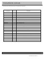
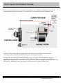
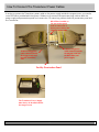
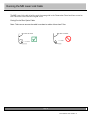
1
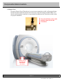
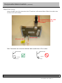
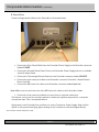
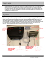
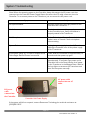
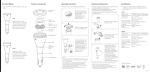
INSTALLATION / OPERATION MANUAL
Part Number: RTC-SS Rev 8
Notes:
Part Number: RTC-SS Rev 8
TABLE OF CONTENTS:
Page
Introduction ..................................................................................
1
Safety Instructions .......................................................................
2-3
Block Diagram .............................................................................
4
Checking Materials ......................................................................
5-6
Room Layout and Installation Overview ...............................…...
7
How to Connect the Transducer Power Cables………………..…
8
Running the MR Laser Link Cable .....................................…....
9
Components Interconnection ...........................................….......
10-12
Control Room Setup ...................................................................
13
Patient Setup ………………........................................................
14
Operation and Troubleshooting...................................................
14-15
Part Number: RTC-SS Rev 8
Introduction
Congratulations on your purchase of the Serene Sound Digital MRI-compatible system. This device
represents more than 24 years of development and state-of-the-art engineering. We are confident this
product will give you the tools you need for comforting the patient while undergoing MRI scans.
This user/installation manual outlines how to properly care for and operate this system.
Thank you for choosing to purchase this system from Resonance Technology, Inc. the leader in fMRI
and MRI patient comfort systems.
Suggestions on how to improve this system are always welcome.
Sincerely,
Mokhtar Ziarati
Resonance Technology, Inc.
President and CEO
Page 1
Part Number: RTC-SS Rev 8
Resonance Technology, Inc., patient safety is our top priority. If the headset becomes damaged, stop using the headset immediately
and notify Resonance Technology, Inc. Customer Service for assistance at (818) 882-1997 or (800) 428-6788. Use of broken
components can cause injury to the clinician or the patient.
Caution: Seizures.
If you have a history of temporary spasms, unconsciousness, or epileptic seizures, consult your doctor before using this
system. Use of this product by such individuals may cause spasms, unconsciousness or seizures. If you experience these
symptoms, stop the using this system immediately and consult your doctor.
System: Warranty and Shelf life
The system comes with a one year warranty on all parts and labor, and a shelf life of two years starting from the day of its
original installation. Resonance Technology, Inc. suggest a maintenance call every six months after the one year original
warranty period to check up on frequently used items such as the patient audio headset and the Technologist Rremote
Control. This way you will make the best use of this system for your facility and your patients.
Caution: Sound Volume.
Avoid using the audio headset on patients at high volume. Hearing expert’s advice against continuous loud and extended
audio play. If your patients experience ringing in their ears, reduce the audio volume or discontinue use the system use
until the patient feels comfortable.
This document contains proprietary information that is protected by copyright. All rights are reserved. No part of this document may be
photocopied or reproduced without prior written consent of Resonance Technology Inc. Information contained in this document is covered by one
or more of the following U.S. patents 5627902, 5877732,5432544, 5412419
Page 2
Part Number: RTC-SS Rev 8
WARNING: Inspect system components that come in contact with the patient prior to use. Discontinue product usage if any damage
is visible or presents other potential hazards. Use of broken components can cause injury to the clinician or the patient.
Caution: MRI Environment Hazards.
Installation of materials inside the MRI suite must be done with extreme caution.
Take care that ferromagnetic materials be kept at least three meters away from the magnet and that no installation shall
be done near the filter panel if a scan is in progress.
In addition, no persons with ferromagnetic prosthetic devices, such as pacemakers or joint replacements, should enter
the MRI suite at any time. Extreme high magnetic fields inside the magnet room have the potential to dislodge items at
high velocities and can result in serious injury, or death.
For questions regarding installation procedures or technical support, call Resonance Technology, Inc. via telephone
Mondays through Fridays, 8 a.m. to 5 p.m. Pacific Standard Time at (818) 882-1997 and via email at
[email protected]
Resonance Technology, Inc. will not be liable for any injury or property damage that occurs as a result of improper
installation procedures or improper use of this system. By agreeing to this notice, users certify that they are familiar with
basic MRI safety procedures and that they have read and understand this notice.
Only system components explicitly designated for use inside the MRI suite should be placed inside the magnet room.
Components not designated for MRI use may present a projectile hazard and can become airborne, causing serious
injury, damage or death.
Caution: Electric Shock.
Failure to observe all operating and maintenance instructions may cause damage to your product, property damage, or
injury or death from electric shock, fire or other causes.
Caution: Do Not Disassemble.
Only trained, authorized personnel should perform any required service on this product. Failure to comply with this
warning may result in property damage, injury or death from electric shock, fire or other causes.
Caution: Avoid Extreme Heat, Wet, Humid, Dusty and Smoky Environments.
This product may be deformed by high temperature, direct sunlight and dropping or other mechanical shock. Do not
expose the unit to rain or moisture.
Caution: Unplug the Product When Not in Use.
Always unplug this product when not in use for extended periods, such as during vacations and MRI maintenance.
Page 3
Part Number: RTC-SS Rev 8
Block Diagram
Serene Sound System Components
AM/FM-CD-Ipod
Iphone Sound System
Serene Sound Transducer
Patient Audio Headset
Serene Sound Controller
Magnet Room
Components
(MRI SAFE)
Technologist Tech Remote Unit
Room Components
(NOT MRI SAFE)
Note: The antenna shown in the Serene Sound Transducer unit is an option for future system features that may not be included
with your system. If the antenna is missing proceed using the system since none of the system functions are affected in any way.
Page 4
Part Number: RTC-SS Rev 8
Checking Materials
Your Serene Sound system comes complete with all the necessary components for full installation at your
site. The following checklist is provided for verification:
Part Number
Quantity
Description
-- Main Items --
RTC-660-170-370-000
RTC-660-050-535-000
RTC-660-050-540-000
RTC-650-050-005-000
RTC-661-050-005-000
RTC-650-050-260W-000
RTC-LPS
RTC-650-020-000-000
RTC-650-062-000-000
RTC-651-060-621-000
RTC-ALS-SFA
RTC-SS
Part Number varies
RTC-650-300-605-000
1
1
1
1
1
1
1
1
1
1
1
1
1
1
Serene Sound Controller
Serene Sound Controller Power Supply
Serene Sound Transducer
Power Supply (For Transducer)
Switching Power Supply
Linear Power Supply (optional)
Linear Power Supply Installation/Operation Manual (optional)
Technologist Remote Control
Audio Headset
Headset Headband
Stereo System
Installation / Operation Manual (This manual)
Filter Plate
9pin D-Sub Filter
RTC-ALS-HEC
RTC-ALS-TWR
RTC-ALS-TWH
RTC-650-060-052-000
RTC-651-000-453-000
RTV-108
RTC-ALS-HDH
17304
50
20
20
10
1
1
1
1
Headset Earpiece Covers
Tie Wraps
Tie Wrap Holders
Headset Microphone Cushions
Patient Headrest
Silicone Glue Tube
Headset Hook
Cable Bundler
RTC-101-102-001-101
1
MR Laser Link Cable
RTC-101-950-003-000
1
RG-59 Antenna Cable - 35 feet
RTC-330-170-404-000
ATS300SP
RTC-101-210-001-101
1
1
1
Mini Stereo to Mini Stereo Cable (male)
“T” FM Transformer for radio antenna
Transducer DC Power Cords (3m)
RTC-101-245-001-001
1
Transducer DC Power Cord (10m)
RTC-101-306-003-000
2
Hospital Grade Power Cords (USA)
RTC-ALS-HGC
2
Hospital Grade Power Cords (Europe, etc)
-- Accessories --
-- Cables --
Page 5
Part Number: RTC-SS Rev 8
Checking Materials (continued)
The following list details placement of all equipment components:
Part Number
Quantity
Description
-- Control Room –
RTC-660-170-370-000
1
Serene Sound Controller
RTC-660-050-535-000
1
Serene Sound Controller Power Supply
RTC-101-306-003-000
1
Hospital Grade Power Cord
RTC-650-020-000-000
1
Technologist Remote Control
RTC-ALS-SFA
1
Stereo System
RTC-660-000-072-101
1
Installation / Operation Manual
RTC-101-950-003-000
ARX-Mini315
1
1
RG-59 Antenna Cable - 35 foot
3.5mm Mini Stereo cable
ATS300SP
1
“T” FM Transformer for radio antenna
(This manual)
-- Inside the Magnet Room -RTC-660-050-540-000
1
Serene Sound Transducer
RTC-101-245-001-001
1
Transducer DC Power Cord (10m long)
RTC-650-062-000-000
1
Patient comfort Audio Headset
RTC-101-102-001-001
1
MR Laser Link Cable
RTC-ALS-HDH
1
Headset Hook
-- On the penetration panel Outside the Magnet Room -RTC-101-102-001-101
1
MR Laser Link Cable
RTC-101-210-001-101
1
Transducer DC Power Cords (3m)
RTC-650-300-605-000
1
DB-9 D-Sub Filter
Part Number varies
1
Filter Plate
Page 6
Part Number: RTC-SS Rev 8
Room Layout and Installation Overview
Below is the standard setup for the Serene Sound system. Your individual installation may vary, but will
generally be distributed in three areas: 1) Control Room, 2) Computer Room and 3) Magnet Room.
The Control Room setup consists of placement and connection of the Serene Sound Controller,
Technologist Remote Control and AM/FM/CD/I-pod/I-phone Stereo system.
A single Laser Link Fiber Optics cable bundle will run from the Serene Sound Controller through the
penetration panel wave-guide to the Serene Sound Transducer. With the exception of the headset, all
Magnet Room Serene Sound components must be placed to the side of the magnet shroud and never in line
with the bore. Additionally, these components should be placed in a lightly trafficked area.
Page 7
Part Number: RTC-SS Rev 8
How To Connect The Transducer Power Cables
In order to connect the Transducer power cable to the power supply outside the magnet room, you need to
use a DB-9 filter provided with the system. Make sure to connect the two meter long cable to both the
power supply and penetration panel and connect the 10 meter long cable to both the penetration panel and
the Transducer.
DB-9 Filter installed on
the penetration panel
used to connect the 2meter power cable to the
10-meter power cable
2 meters long power
cable connected outside
the magnet room into
the DB-9 filter and
power supply.
10 meters long power
cable connected inside
the magnet room and
into the Transducer
unit.
Facility Penetration Panel
The Transducer Power Supply
must always be installed outside
the magnet room.
Page 8
Part Number: RTC-SS Rev 8
Running the MR Laser Link Cable
The MR Laser Link cable is fed through the wave-guide in the Penetration Panel and then routed to
the Transducer unit inside the magnet room.
Caring For the Fiber Optics Cable:
Note: Take care to ensure the cable is not bent in radius of less than 15cm.
MR Laser Link Cable
MR Laser Link Cable
r
r ≥ 15 cm
r
r < 15 cm
Page 9
Part Number: RTC-SS Rev 8
Components Interconnection
A. Magnet Room
Place the Serene Sound Transducer in a secure area away from traffic as illustrated below.
Install the audio headset firmly into the Transducer using the bracket provided. Make sure
that the audio headset connector is connected all the way into the Transducer audio socket
for proper installation.
Press down firmly on the audio
headset connector into the
Transducer.
SERENE SOUND
TRANSDUCER
PREFERRED
LOCATION
Page 10
Part Number: RTC-SS Rev 8
Components Interconnection
(continued)
Magnet Room (cont’d)
Attach the MR Laser Link connectors to the Transducer as illustrated below. Match the cable colors
to those on the unit’s labels.
Press down firmly on the audio
headset connector into the
Transducer.
Fiberlink cable
DC power cable
Note: Remember not to bend the individual cables smaller than a 15 cm radius.
Individual Cable
Individual Cable
r
r≥15 cm
r
r<15 cm
Page 11
Part Number: RTC-SS Rev 8
Components Interconnection
(continued)
B. Control Room
Connect all appropriate cables to the Controller as illustrated below.
•
Connect the 5-pin Round Cable from the Controller Power Supply to the Controller connector
labeled POWER.
•
Connect the Hospital Grade Power Cord to the Controller Power Supply and into an available
active AC power outlet.
•
Connect the Technologist Remote Control to the Controller connector labeled REMOTE.
•
Connect the mini stereo jack cable to the Controller connector Controller* labeled Control
Room Audio IN.
•
Connect the MR Laser Link cable to the Controller connector labeled Optic Link.
Note: Make sure to match the color of the MR Laser Link cables to the Controller’s labels.
• Connect the mini stereo jack cable from record-out to computer audio input.
This feature can be used to record the patients’ headset microphone response into a computer
microphone input. This is an optional feature.
Apply power to the Controller first and then turn on the Transducer Power Supply. Wait until the
system is fully synchronized (logo lights rotating on the Transducer inside the Magnet Room).
*The
Controller is IPOD and Iphone ready.
Page 12
Part Number: RTC-SS Rev 8
Control Room Setup
TECHNOLOGIST REMOTE CONTROL OPERATION:
Notice: Always adjust the audio input source to a level that will not cause distortion. Otherwise
a crackling noise will be heard on the patient audio headset!
!
Wheel #1: Patient Audio Volume (scroll up and down to adjust)
Scrolling the wheel up increases the patient’s headset volume.
Scrolling the wheel down decreases the patient’s headset volume.
Technologist Microphone – Press and hold the talk button. Then scroll the adjustment wheel
This adjustment is to change the volume that the patient can hear during communication.
Wheel #2: Patient Microphone Volume (scroll up and down to adjust)
Scrolling the wheel up increases the volume of the patient’s microphone volume heard in the control room.
Scrolling the wheel down decreases the volume of the patient’s microphone.
Wheel #3: Main Volume (scroll up and down to adjust)
Scrolling the wheel up increases the control room volume (you need to connect external speakers to the Controller).
Scrolling the wheel down decreases the control room volume.
Wheel #4: Main Menu (scroll and press to select sub-menu items)
Pressing down on this wheel activates the system menu. Scrolling the wheel up or down rotates through the system
functions. To set the patient microphone in AUTO or MANUAL mode always press on the TALK button to activate either
mode. The MANUAL mode is used to mute the patient’s microphone during scanning. To adjust your technologist
microphone volume built into the technologist remote unit, simply press on the TALK button and at the same time scroll the
wheel #1 to set the PTT volume to about 60 to 70. If your voice sounds too loud in the patient’s audio headset lower the
PTT volume.
Please Note: If the tech remote
unit is not responding you can
reset it to its original factory
default settings by following these
5 simple steps:
1 : Set Patient Audio (Adjustment
Wheel #1) to 1
st
2 :Set Patient Microphone
(Adjustment Wheel #2) to 2
nd
3 : Set the Main Volume
(Adjustment Wheel #3) to 3
rd
#1
#2
#3
#4
4 : Press and hold talk button for
15 seconds
th
5 : Release the talk button. All the
settings have been reset to the
original factory defaults. You now
have to re-adjust all the wheels
settings.
th
Page 13
Part Number: RTC-SS Rev 8
Patient Setup
Make sure all cables have been connected securely into the Transducer and that the components do
not impede walkways. Ensure that the Transducer is not placed directly in front of the magnet bore or
directly under the bed. Before placing the headset on the patient, make sure that the technologist
microphone volume has been set to a comfortable level for the patient. Place the audio headset over
the patient’s ears and adjust the headband. If necessary, position the headset microphone about one
cm. away from the patient’s mouth.
Operation
When operating normally, the logo lights on the Transducer are rotating and the sides of the Controller are
blue. However, after two to three hours of non-operation, the system goes into a SLEEP mode and the
system appears to be turned off. To wake up the system, just press down once on the TALK button of the
Technologist Remote Control and wait for the system to synchronize completely. Remember to always
communicate with the patient to adjust the headset audio volume. Always start at a low setting progressively
to a higher setting until the patient can hear you clearly. Read the stereo system user manual for its
operation. Below is an illustration how to connect the control room components:
Technologist
Remote Control
AM/FM/CD/Ipod/
Iphone Stereo
System
Controller
Audio input cable
from the stereo
system
FM radio antenna
Audio ouput cable
connects into the
Controller
Stereo system power
cord
Controller DC power
cord attached to the
Controller Power
Supply
Fiber optics cable that
connects to the
Transducer in the
Magnet Room
Page 14
Part Number: RTC-SS Rev 8
System Troubleshooting
Note: When disconnecting power to the Controller, always disconnect the AC power cord that
connects into the Controller Power Supply. Never disconnect the DC cable connector from the
Controller. To re-connect power to the Transducer, just re-connect the AC power cord.
Symptom
Verify
No Synchronization
The fiber optics are in the right position on the
Controller and Transducer.
No Audio
Check the mini-stereo cable properly connected
on the Controller input. Verify the headset is
properly seated in the Transducer.
No Microphone
On the Technologist Remote Control, check comm
mode is auto or manual. Check microphone
volume setting.
System Reboots
Unplug the power supply from the A/C outlet.
Unplug the Controller; turn off the power supply
for the Transducer.
If the system hangs up* or fails to respond to the
Technologist Remote Control commands.
Power down the Controller for approximately 10
seconds and then power up again.
If the system still does not respond.
Power down the complete system for
approximately 10 seconds, then power up the
Controller first in the Control Room, then power
up the Transducer in the Magnet Room. Wait for
the logo lights to rotate on the Transducer and
then use the system normally.
*System Hang up is when the system refuses to function normally.
AC power cable
connects into an AC
outlet.
DC power
cable
connects into
the Controller.
Controller Unit Power Supply
If the system still fails to respond, contact Resonance Technology for technical assistance at
(818)882-1997.
Page 15
Part Number: RTC-SS Rev 8
Part Number: RTC-SS Rev 8