1
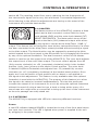
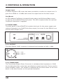
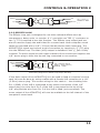
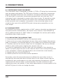
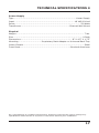
ACOUSTI-Q Tube Preamplier/Blender USER’S MANUAL 1.0 Copyright © 2001, PreSonus Audio Electronics, Inc. ALL RIGHTS RESERVED TABLE OF CONTENTS 1 1.1 1.2 Overview.................................................................................. 1 Introduction ............................................................................... 1 Features .................................................................................... 2 2 2.1 2.1.1 2.1.2 2.1.3 2.1.4 2.1.5 2.2 2.2.1 2.2.2 2.2.3 Controls & Operation................................................................ 4 Front Panel................................................................................. 4 Gain Controls/Blender.................................................................. 5 Notch Filter ................................................................................ 6 Equalizer.................................................................................... 7 Master ....................................................................................... 9 Metering .................................................................................... 9 Back Panel ............................................................................... 10 Output..................................................................................... 10 Tuner/Amp ............................................................................... 10 Effects Loop ............................................................................. 11 3 3.1 3.2 3.2.1 3.3 Connections ........................................................................... 12 Instrument Input/Blender .......................................................... 12 Vacuum Tubes .......................................................................... 12 Replacing The Vacuum Tube ....................................................... 12 Wiring Scenerios ....................................................................... 15 4 Technical Specications ......................................................... 16 5 PreSonus Limited Warranties ................................................. 18 i OVERVIEW 1 1.1 INTRODUCTION Thank you for purchasing the PreSonus ACOUSTI-Q Tube Preamp/Blender. This preamp was designed using state of the art components to deliver crystal clear audio for an innite period of time. We believe the ACOUSTI-Q Tube Preamp/Blender to be an exceptional sounding unit and an exceptional value. Please contact us at 1-800-750-0323 with your questions or comments regarding this product. PreSonus Audio Electronics is committed to constant product improvement and believes the best way to accomplish this task is by listening to the experts on our gear, our valued customers. We appreciate the support you have shown us through the purchase of this product. Please pay close attention to how you connect your ACOUSTI-Q to your system. Improper grounding is the most common cause of noise problems found in studio or live sound systems. We urge you to scan this manual before hooking up your ACOUSTI-Q to familiarize yourself with its features and applications. Good luck and enjoy your ACOUSTI-Q! 1 1 OVERVIEW 1.2 FEATURES The following is a summary of your ACOUSTI-Q’s features: Dual Input Stage Your ACOUSTI-Q contains two separate dual servo preamps with separate volume controls. This award-winning design provides ultra low noise performance and wide dynamic control for both preamps giving the ACOUSTI-Q the ability to boost the desirable signals without increasing unwanted background noise Blender Control Separate volume controls are provided for mixing the input signals. This is accomplished by way of a dual concentric volume control for blending incoming signals to the 1⁄4” TRS input jack. 12AX7 Tube The input signal is routed through a 12AX7 vacuum tube after the Master output. This design applies the aural enhancement capabilities of the tube on the input while minimizing unwanted audio artifacts. 12V Phantom Power The ACOUSTI-Q has +12VDC Phantom power available to the Ring of the 1⁄4” TRS input. When the Phantom power switch is engaged, +12VDC power is supplied for use by mini-condenser microphones installed in some acoustic instruments. Use caution when engaging the Phantom power switch as a loud transient may occur. Phase A phase reverse switch is provided to enable the user to invert the phase of the input signal. Engaging the phase switch can compensate for different connector hook-ups. Varying the signal’s phase may also be used to achieve an intentional ‘out-of-phase’ sound. Experiment! Notch Filter The ACOUSTI-Q has a Notch lter on the front panel for isolating and controlling low frequencies that may be prone to feedback. 2 OVERVIEW 1 Equalizer The ACOUSTI-Q Equalizer section has a pair of dual concentric potentiometers. The left inner control is a sweepable Mid-Range control and allows the user to select a frequency from 250Hz to 5kHz while the left outer control cuts/boosts the selected frequency +/- 12dB. The right side inner control, which is labeled Brilliance, boosts or cuts (+/- 12dB) 8kHz and above while the outer left side control in the Equalizer section, which is labeled Bass, boosts or cuts (+/- 12dB) 100Hz and below. Master Section The Master section of the ACOUSTI-Q contains a Mute switch and a dual concentric control for use in setting the level of the Main output and the level of the Cut/Boost feature*. The Mute feature is provided for use in conjunction with an external tuner. Engaging this switch mutes the Main output while allowing the signal to remain present at the -20dB AMP/TUNER output. *Activation of the Volume Cut/Boost feature requires use of an optional external footswitch which also provides footswitch operation of the Mute function. The footswitch may be purchased at your authorized PreSonus Dealer. 3 2 CONTROLS & OPERATION 2.1 FRONT PANEL The front panel of the ACOUSTI-Q contains: POWER OUTPUT LEVEL (dBu) -42 -36 -30 -24 -18 -12 TUBE PREAMP NOTCH -3 0 3 CUT/BOOST 6 0 293 10 TIP (CH 1) RING (CH 2) -6 9 12 15 18 24 EQUALIZER 0 1k MASTER 0 0 0 +12V MUTE 3(dB) INPUT PHASE 30 TIP GAIN RING GAIN -12 92 494+12 FREQ LEVEL -12 250 +/- 12dB 5k+12 FREQ LEVEL +/- 12dB -12 +12 BRILLIANCE BASS -12 -80 +20+12 LEVEL CUT/BOOST PEDAL +/- 12dB Preamp Instrument (1⁄4”) input (TIP Ch.1; RING Ch.2) Phase Switch +12V Phantom Power Switch Blender Control (separate Gain control for Tip and Ring) Notch Notch Filter Control (Frequency and Level) Equalizer Sweepable Mid Range Separate Frequency Selector and Level Cut/Boost control (+/- 12dB) Separate Brilliance and Bass controls (+/- 12dB) Master Mute (Main out) Level (-80/+20) and Cut/Boost (+/-12) LED Indicators Power Output Level (-42/+24dBu) Cut/Boost Phantom Power Phantom Power (12 Volts) is provided to the RING of the input connector of the ACOUSTI-Q for powering mini-condenser microphones installed in acoustic instruments. These microphones are typically utilized in conjunction with a transducer-style pick-up. The 12VDC supplied by way of the RING portion of 4 CONTROLS & OPERATION 2 the TRS connector is designed to fulll the power requirements of the internal mini-condenser microphone and is not intended to supply the necessary current to replace the 9V battery needed by many types of on-board preamps installed in acoustic instruments. Tip Sleeve Ring Tip Sleeve Ring Tip TIP = Pick-Up Ring RING = 12V DC, Sleeve Mic or Pick-Up SLEEVE = GND Cable Wiring Diagram for Phantom Power TRS Plug LE SS E OR M 2.1.1 GAIN CONTROLS/BLENDER The ACOUSTI-Q Gain potentiometers give the user independent control over the amount of input signal from the Tip (Ch.1) and Ring (Ch.2). The Blender feature lets you change the characteristics of the ampli3(dB) 30 ed sound of your instrument if it is equipped with both a mini-condenser mic and a pick-up. A variety of tonal shadings are available by simply adjusting the relationship between the signals from the mini-condenser mic and the pick-up. 10 For example, the low end of the instrument’s sound can be accentuated by blending the mini-condenser mic level louder than the output from the transducer (pick-up). This setting will typically result in a darker, rounder sound. The mini-condenser microphone will reproduce the sound emanating from inside the instrument, which will have greater bass content than the pick-up, which is designed to reproduce the vibrations from the instrument’s body. On the other hand, favoring the pick-up over the mini-condenser mic will result in a sound that is brighter and punchier and will bring out the percussive qualities of the performance. The Blender feature provides a palette of subtle tonal colors for instruments equipped with both a mini-condenser mic and a pick-up. Feel free to paint your sound. Remember to turn the Master level OFF (outer Gain control fully counterclockwise) BEFORE the phantom power is turned ON – for instruments equipped with mini-condenser microphones. Powering up the phantom power for the mini-condenser mic with the Master turned up may result in VERY LOUD feedback, which could damage your loudspeakers! 5 2 CONTROLS & OPERATION Phase The phase of the signal from the mic may be reversed to change it’s sound. The inverted phase results in a signal that sounds more wooden and hollow. This sound is much like the sound of single coil pick-up electric guitars such as the Fender® Stratocaster™. It can be especially effective for rhythm guitar. LE SS E OR M 2.1.2 NOTCH FILTER The ACOUSTI-Q has been outtted with a Notch lter for controlling feedback without greatly altering the instrument’s sound. A Notch lter affects a very narrow frequency bandwidth with minimal overlap into 494+12 -12 92 adjacent frequencies. This is why a Notch lter can virtually eliminate a feedback problem while retaining an instrument’s original sound. The dual concentric control for the Notch lter has an inner knob that selects the frequency to be ltered and an outer knob to select how much the selected frequency is boosted or how much the selected frequency is reduced. 0 293 Frequency The Frequency control (inner knob) of the Notch lter’s dual concentric control is labeled FREQ. The frequencies governed by this control are graduated incrementally from 92Hz (inner knob rotated completely counter-clockwise) to 494Hz (inner knob turned completely clockwise). These frequencies are effective at controlling feedback because they correspond to the speed of the vibrations of specic musical notes (ex. 92Hz=F#) that may resonate (feedback) inside an acoustic instrument such as a guitar. The shape of the instrument, the density of the material from which it was manufactured, as well as the volume that the instrument’s signal is being amplied and reverberates inside the instrument all play a role in why an amplied acoustic instrument may feedback. Level The Level control is the outer knob of the Notch lter’s dual concentric control. Notice that the markings for this control have a zero (0) at the twelve o’clock (straight up and down) position. With the outer knob set at this position, the Notch lter has no effect on the signal. Rotating the control fully counter clockwise reduces (cuts) the frequency that has been selected by twelve dB (12dB). Bringing the knob back to the top or twelve o’clock position adds back the selected frequency until it is completely restored at the twelve o’clock (0) 6 CONTROLS & OPERATION 2 position. The Level of the selected frequency can be increased (boosted) by rotating the outer knob of the Notch lter clockwise from the twelve o’clock (0) position. This boost can be by as much as twelve dB (+12). Care should be exercised when boosting the instrument’s signal with the Notch lter so as to not cause a feedback problem. The Notch lter can be effective at boosting a decient frequency, however, the Bass control of the Equalizer section of the ACOUSTI-Q should be the rst choice for increasing the low end of an instrument’s voice. Setting the Notch Filter for an Acoustic Guitar As stated previously, the Notch lter is controlled by way of a dual concentric potentiometer. The inner knob allows selection of a frequency from 92Hz to 494Hz and the outer knob can cut or boost the selected frequency’s level by as much as 12dB. Begin by turning the Frequency selector fully counter clockwise and placing the Level control in the twelve o’clock (0) position. Press down on the lowest string at the rst fret. Continue fretting the lowest string moving up the neck one fret at a time until the resonant frequency is located. While keeping the note on the guitar fretted, turn the Boost/Cut (outer control) counterclockwise about halfway. Slowly rotate the Frequency control from the 92Hz position, clockwise, until the feedback is reduced. Try to zero in on the feedback by very slowly advancing the frequency controller past the point at which the feedback was initially reduced. If the level of the feedback increases, go back to the point where it was encountered. You have found the offending frequency and reducing or eliminating it is now simply a matter of rotating the Level (outer control) of the Notch lter. LE SS LE SS 5k+12 -12 E OR M -12 250 0 E OR M 0 1k +12 2.1.3 EQUALIZER The ACOUSTI-Q Equalizer has two dual concentric controls. A sweepable Mid-Range control and a Brilliance/Bass control. Mid-Range Controls The dual concentric Mid-Range control has a Frequency selector (inner knob) and a Level control (outer knob). The Frequency control is labeled FREQ and is graduated incrementally from 250Hz (completely counter clockwise) to 5kHz (fully clockwise). The Level can be cut 12dB (completely counter clockwise) or 7 2 CONTROLS & OPERATION boosted (fully clockwise) by as much as 12dB. As a rule, it is preferable to cut a frequency rather than to boost one. The ear is more sensitive to frequency boosts than it is to cuts and, therefore, the effect of boosting a frequency is much more pronounced. The Level control has no effect on a selected frequency in the twelve o’clock position. Rotating the Level control counter clockwise can reduce the selected frequency, as well as adjacent frequencies, by as much as (-12) twelve dB. Turning the Level control clockwise can boost the selected and adjacent frequencies by as much as (+12) twelve dB. This control has a Q that is equal to 1. This means that the center frequency, the frequency selected by using the Mid-Range frequency selector, is cut or boosted the most while frequencies on either side of the selected frequency are also affected but to a lesser and lesser extent, the farther they are from the selected center frequency. So while you may select 1kHz to boost by +6 dB, remember you are also boosting 1.1 kHz and 900Hz to a slightly lesser extent and 1.2kHz and 800Hz a little less than 1.1 kHz and 900 Hz, etc. Brilliance/Bass Control The Brilliance/Bass dual concentric control can be used for boosting or cutting the frequencies of 8kHz and above and 100Hz and below by as much as +/12 dB. The inner dual concentric control is labeled Brilliance. The frequencies of 8kHz and above can be increased or decreased by adjusting this knob. The twelve o’clock position is zero and no effect on the high frequencies is heard. By rotating the Brilliance control clockwise from the twelve o’clock (0) position, the brighter, more treble portion of the signal becomes more pronounced. If the instrument seems dull and lifeless, boosting the brilliance control results in a sound with more air and sparkle. If the instrument’s sound seems thin, rotating the Brilliance control counter clockwise can reduce the harsh quality and make the overall tone of the instrument rounder and more full range. A little adjustment goes a long way and gradual adjustment of this control produces a much more pleasing sound than extreme positions. The outer dual concentric control is labeled Bass. As it’s name implies, this control adjusts the Bass frequencies from 100Hz and below. Once again, the twelve o’clock position corresponds to zero boost or cut. No effect is exerted over the low frequencies of the signal while the control remains in this position. The Bass frequencies (100Hz and below) can be boosted by rotating this control clockwise. The instrument’s tone becomes smoother and richer. Over adjustment of the Bass control can result in a mufed sound and can induce feedback if care is not taken. Conversely, counter clockwise rotation of the Bass control from the twelve o’clock (0) position can reduce 100Hz and below by as much as 8 CONTROLS & OPERATION 2 twelve dB. The resulting sound from overly reducing the low frequencies of the instrument’s signal can be very thin and harsh. Incremental adjustments while listening to the effect the adjustments are having on the sound of the instrument will yield the best results. LE SS E OR M 2.1.4 MASTER The Master section of the ACOUSTI-Q contains a Mute switch and a dual concentric control with the inner knob labeled LEVEL and the outer knob labeled CUT/ BOOST FOOTSWITCH. The Mute switch turns off the +20+12 -12 -80 signal at the Main (XLR) balanced output while allowing the signal to remain at the Amp/Tuner -20dB 1⁄4” output. This feature lets the performer tune his/her instrument silently if a tuner has been connected to the Amp/Tuner output provided without sending a signal to the Main output. The Mute function may be engaged by pressing the Mute switch located on the front panel to the ON position or by engaging this function by way of the optional footswitch. The dual concentric control of the Master section is used to set the output level of the ACOUSTI-Q. The inner knob adjusts the output Level of the unit’s Main output. The Level control adjusts from 80 (fully counter clockwise) to +20 (completely clockwise) which is the loudest position. Unity (zero) occurs at the twelve o’clock position. The outer knob is labeled Cut/Boost Footswitch and adjusts from 12 (rotated fully counter clockwise) to +12 (completely clockwise) at the loudest boost position. Once again zero is at the twelve o’clock position with no boost or cut applied to the signal at this adjustment. This feature is only available when the optional footswitch is used with the ACOUSTI-Q. The purpose of this feature is to allow the signal to be raised or lowered instantaneously. This lets the performer increase the output of his instrument for a solo by using the optional footswitch without the need of using a hand to turn a knob or being at the mercy of a sound man who might miss a cue and fail to bring up the level of the instrument so the solo passage can really stand out. 0 0 2.1.5 METERING The ACOUSTI-Q is equipped with LED’s for observing different functions: Power A red LED indicator labeled POWER is located at the top of the front panel above the input level controls. This LED is lighted when power is supplied to the unit by plugging in the power supply. 9 2 CONTROLS & OPERATION Output Level A sixteen segment LED meter has been provided to monitor the output level. It goes from 42dBu to +24dBu and meters the signal level at the Main output. Cut/Boost An LED labeled Cut/Boost is located directly above the Brilliance/Bass control on the top of the ACOUSTI-Q front panel. This LED is lighted when the optional Cut/Boost footswitch is engaged. 2.2 BACK PANEL The back panel of the ACOUSTI-Q contains the input for the power supply and optional footswitch, the 20dB Tuner/Amp output, the insert for the Effects Loop and the Main Output (XLR) POWER 18 VAC Tip = Mute Ring = Cut/Boost Sleeve = GND Tuner/Amp Tip = Output Ring = Input Sleeve = GND Footswitch -20dB Output Effects Loop ACOUSTI-Q TUBE ACOUSTIC PREAMP/BLENDER Created, Designed and Manufactured by PreSonus Audio Electronics In The USA Main Output 2.2.1 OUTPUT The Main Output (XLR) connector is balanced and operates at 0dB = 0dBu. 1 2 PIN 1 = GND PIN 2 = High (+) PIN 3 = Low (-) 3 Cable Wiring Diagram for Input and Output XLR 2.2.2 TUNER/AMP The Tuner/Amp Output Phone Connector is unbalanced and operates at -20dB. As the label describes, it has been provided as a signal source for Tuners and for guitar amplier inputs. This output is unaffected by the Mute switch on the front panel or the Mute function on the optional footswitch. 10 CONTROLS & OPERATION 2 Sleeve Tip Sleeve Tip Ring Tip TIP = High (+) Sleeve SLEEVE = GND (-) Cable Wiring Diagram for Tuner/Amp Output Phone Plug 2.2.3 EFFECTS LOOP The Effects Loop jack is designed for use with outboard effects such as compressors, delay units, or reverbs. A ‘Y’ cord with one TRS 1⁄4’’ connector to two 1⁄4” TS is required to use this function. This Effects Loop output jack can also be used to supply the audio feed for a sound card. Most computer sound cards are provided with a 1/8” (3.5mm) female stereo audio input jack. The ACOUSTI-Q’s signal can be sent to this connection by inserting a 1⁄4” (TS) plug into the Effects Loop. The Main (XLR) output is defeated if the 1⁄4” jack is fully inserted. To send a signal to both input channels of the sound card requires the 1/8” stereo plug to have the tip and ring connected to one another. Sleeve Ring Tip Tip Sleeve Ring TIP = Output (Send) RING = Input (Return) SLEEVE = GND Cable Wiring Diagram for Effects Loop Output TRS Plug If the Main output of the ACOUSTI-Q is to be used to feed a computer’s sound card, this can be done by using a cable with a female XLR connector to a 1/8” (3.5mm) stereo plug. The correct wiring for this cable is – the shielding from Pin 1 (GND) of the XLR is connected to the sleeve connection of the 1/8” stereo plug, the wire from Pin 2 of the XLR is connected to the tip of the 1/8” plug and the wire from Pin 3 of the XLR is lifted (not connected). The mono output of the ACOUSTI-Q will now be available to the left channel of the computer’s sound card. 11 3 CONNECTIONS 3.1 INSTRUMENT INPUT/BLENDER The instrument input is designed to handle 1⁄4” TRS or TS plug from instruments such as guitars and basses. The TRS style connector is used with instruments that are equipped with both mini-condensor microphones and piezo pick-ups. A TS style jack is used with instruments equipped with only pick-ups. This instrument input is designed to accept either type of plug. (It should be noted that the Blender function requires the output of an instrument that has both a pick-up and a mini-condensor microphone.) Care should be taken not to overdrive the input of the ACOUSTI-Q with instrument preampliers or line level output. 3.2 VACUUM TUBES The ACOUSTI-Q comes supplied with a 12AX7 vacuum tube that provides excellent performance characteristics. We expect some owners of the ACOUSTI-Q will try different brands of 12AX7 tubes to investigate the various performance possibilities they might provide. 3.2.1 REPLACING THE VACUUM TUBE 1. Disconnect the ACOUSTIC-Q from it’s electrical outlet. 2. Remove the six screws that attach the top of the unit’s chassis. The vacuum tube is mounted in a horizontal fashion in the middle of the ACOUSTI-Q’s body. 3. Carefully remove the vacuum tube from it’s receptacle. Be sure to hold the socket in place while gently wiggling the vacuum tube out. 4. Insert the replacement vacuum tube into the receptacle. Care should be taken to properly align the pins on the vacuum tube to the corresponding holes in the receptacle. (Caution should be taken not to break the circuit board.) 5. Replace the top of the ACOUSTIC-Q. 6. Restore power to the unit and resume operation. Remember, tube life and performance are affected by how often a tube is used and by how hard the tube is driven when in use. Signs of wear may be exhibited by poor performance or by the tube becoming microphonic. Periodic replacement of vacuum tubes is recommended. The time interval for tube replacement may vary greatly. If you notice deterioration in sound quality of the ACOUSTI-Q then it’s time to change the tube. 12 CONNECTIONS 3 Mounting Diagram for the PreSonus Amp/Stand Mount 13 3 CONNECTIONS 3.3 WIRING SCENERIOS Foot Pedal (Optional) A = TRS B = TRS AMP Amp C = TS D = TS Effects Loop E = TRS F = TS G = TS Sound Card H = TS I = 1/8” Stereo Mixer J = XLR (Female) K = XLR (Male) POWER 18 VAC ACOUSTI-Q TUBE ACOUSTIC PREAMP/BLENDER Created, Designed and Manufactured by PreSonus Audio Electronics In The USA FOOT PEDAL MUTE Possible ACOUSTI-Q Hook-Up Scenerios 14 CUT/BOOST CONNECTIONS 3 P MIXER Tip = Mute Ring = Cut/Boost Sleeve = GND Tuner/Amp Tip = Output Ring = Input Sleeve = GND Footswitch -20dB Output Effects Loop Q R d A EFFECTS PROCESSOR Main Output SOUND CARD Possible ACOUSTI-Q Hook-Up Scenerios 15 4 TECHNICAL SPECIFICATIONS Input 1⁄4” TRS Impedance, TIP......................................................................10 Meg Ohms Impedance, Ring ............................. 10 Meg Ohms (No +12V Phantom Power) 3.2K Ohms (With +12V Phantom Power) Output Main Output Impedance, XLR ......................................... 51 Ohms (Balanced) -20dB Tuner/Amp ...................................................... 51 Ohms (Unbalanced) Sleeve = Ground .............................................................................. (GND) Effects Loop Tip = Output/Send .................................................... 51 Ohms (Unbalanced) Ring = Input/Return ................................................................... 50K Ohms Sleeve = Ground .............................................................................. (GND) Performance THD + Noise (Unweighted) ......................................... 0.005% (0dBu output) 0.05% (+10dBu output) 0.3% (+20dBu output) Signal to Noise................................................................................ >90dB Amplier Type ............................................................................Dual Servo Panel Controls +12VDC Phantom Power (Ring Only) Phase Invert (Ring Only) Tip Gain ................................................................................... 0dB - 40dB Ring Gain ................................................................................. 0dB - 40dB Notch Filter (+/-12dB) .............................................................. 92 - 494 Hz Equalizer (+/- 12dB)........................................................250Hz - 5kHz Bass Bass (+/- 12dB) ............................................................................... 400Hz Brilliance (+/- 12dB)........................................................................... 8kHz Mute................................................................................Main Output Only Master Level ........................................................................ -80dB - +20dB Cut/Boost (Footswitch Only) ........................................................... +/-12dB Metering LED ....................................................................................... -42Bu to clip 16 TECHNICAL SPECIFICATIONS 4 Power Supply Type ..................................................................................... Linear Supply Input ..................................................................................18 VAC/100mA Power ..........................................................................................20 Watts Transformer .................................................................. External Wall Mount Physical Weight ............................................................................................. 7 lbs. Size ............................................................................................... U Rack Dimensions....................................................................... 8” X 4.5” X 1.75” Mounting............................... Proprietary Rack Adapter or Universal Rack Tray Insert Chassis .................................................................................... Steel Front Panel .....................................................................Brushed Aluminum As a commitment to constant improvement, PreSonus reserves the right to change any specication stated herein at any time in the future without prior notication. 17 5 PRESONUS LIMITED WARRANTY IN THE UNITED STATES PreSonus Audio Electronics Inc. warrants this product to be free of defects in material and workmanship for a period of one year from the date of original retail purchase. This warranty is enforceable only by the original retail purchaser. To be protected by this warranty, the purchaser must complete and return the enclosed warranty card within 14 days of purchase. During the warranty period PreSonus shall, at its sole and absolute option, to either repair or replace, free of charge, any product that proves to be defective on inspection by PreSonus or its authorized service representative. To obtain warranty service, the purchaser must rst call or write PreSonus at the address and telephone number printed below to obtain a Return Authorization Number and instructions of where to return the unit for service. All inquiries must be accompanied by a description of the problem. All authorized returns must be sent to the PreSonus repair facility postage prepaid, insured and properly packaged. PreSonus reserves the right to update any unit returned for repair. PreSonus reserves the right to change or improve the design of the product at any time without prior notice. This warranty does not cover claims for damage due to abuse, neglect, alteration or attempted repair by unauthorized personnel, and is limited to failures arising during normal use that are due to defects in material or workmanship in the product. Any implied warranties, including implied warranties of merchantability and tness for a particular purpose, are limited in duration to the length of this limited warranty. Some states do not allow limitations on how long an implied warranty lasts, so the above limitation may not apply to you. In no event will PreSonus be liable for incidental, consequential or other damages resulting from the breach of any express or implied warranty, including, among other things, damage to property, damage based on inconvenience or on loss of use of the product, and, to the extent permitted by law, damages for personal injury. Some states do not allow the exclusion of limitation of incidental or consequential damages, so the above limitation or exclusion may not apply to you. This warranty gives you specic legal rights, and you may also have other rights, which vary form state to state. This warranty only applies to products sold and used in the United States of America. For warranty information in all other countries please refer to your local distributor. PreSonus Audio Electronics, Inc. 7257 Florida Blvd. Baton Rouge, LA 70806 (225) 216-7887 Copyright © 2001, PreSonus Audio Electronics, Incorporated. All rights reserved. 18 PRESONUS LIMITED WARRANTY 5 OUTSIDE OF THE UNITED STATES PreSonus Audio Electronics products are warranted only in the country where originally purchased, through the authorized PreSonus distributor in the country of original purchase, against defects in material and workmanship. The specic period of this limited warranty shall be that which is described to the original retail purchaser by the authorized PreSonus dealer or distributor at the time of purchase. PreSonus does not, however, warrant its products against any and all defects: 1) arising Out of materials or workmanship not provided or furnished by PreSonus, or 2) resulting from abnormal use of the product or use in violation of instructions, or 3) in products repaired or serviced by other than authorized PreSonus repair facilities, or 4) in products with removed or defaced serial numbers, or 5) in components or parts or products expressly warranted by another manufacturer. PreSonus agrees, through the applicable authorized distributor in the country of original retail purchase, to repair or replace defects covered by this limited warranty with parts or products of original or improved design, at its option in each respect, if the defective product is shipped prior to the end of the warranty period to the designated authorized PreSonus warranty repair facility in the country where purchased, or to the PreSonus factory in the U.S., in the original packaging or a replacement supplied by PreSonus, with all transportation cost and full insurance paid each way by the purchaser or owner. All remedies and the measure of damages are limited to the above services. It is possible that economic loss or injury to person or property may result from the failure of the product; However, even if PreSonus has been advised of this possibility, this limited warranty does not cover any such consequential or incidental damages. Some states or countries do not allow the limitations or exclusion of incidental or consequential damages, so the above limitation may not apply to you. Any and all warranties, express or implied, arising by law, course of dealing, course of performance, usage of trade, or otherwise, including but not limited to implied warranties of merchantability and tness for a particular purpose, are limited to a period of two years from either the date of original retail purchase or, in the event no proof of purchase date is available, the date of manufacture. Some states or countries do not allow limitations on how long an implied warranty last, so the above limitations may not apply to you. This limited warranty gives you specic legal rights, and you may also have other rights which vary from state to state, country to country. PreSonus Audio Electronics, Inc. 7257 Florida St. Baton Rouge, LA 70806 (225) 216-7887 Copyright © 2001, PreSonus Audio Electronics, Incorporated. All rights reserved. 19