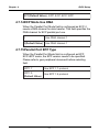
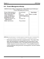
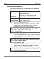
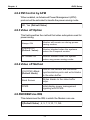
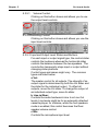
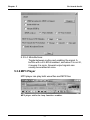
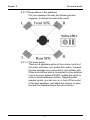
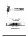
1
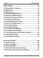
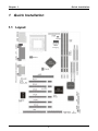
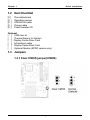
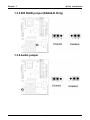
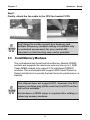
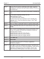
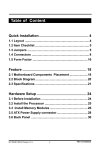
Table of Content
Quick Installation ................................................. 4
1.1 Layout............................................................................ 4
1.2 Item Checklist ................................................................ 5
1.3 Jumpers ........................................................................ 5
1.4 Connectors ................................................................... 8
1.5 Form Factor ................................................................. 16
Feature ................................................................ 18
2.1 Motherboard Components Placement ..................... 18
2.2 Block Diagram ............................................................. 20
2.3 Specifications ............................................................. 21
Hardware Setup ................................................. 24
3.1 Before Installation ...................................................... 24
3.2 Install the Processor ................................................... 25
3.3 Install Memory Modules ............................................. 28
3.4 ATX Power Supply connector ................................... 30
3.5 Back Panel ................................................................... 32
KK266/KK266-R Version 1.1A
1
FB11351020000
Chapter 1
Quick Installation
BIOS Setup ......................................................... 34
4.1PhoenixNet Introduction ............................................. 34
4.2 BIOS Setup .................................................................. 37
4.3 Main Menu ................................................................... 39
4.4 Standard CMOS Features ........................................... 40
4.5 Advanced BIOS Features............................................ 45
4.6 Advanced Chipset Features ....................................... 51
4.7 Integrated Peripherals ................................................ 55
4.8 Power Management Setup ......................................... 62
4.9 PnP/ PCI Configurations ............................................ 69
4.10 PC Health Status ....................................................... 72
4.11 Iwill Smart Setting ..................................................... 73
4.12 Load Fail Safe Defaults ............................................ 76
4.13Load Optimized Defaults ........................................... 77
4.14 Set Supervisor/ User Password Setting ................. 78
4.15 Save & Exit Setup ..................................................... 80
4.16 Exit Without Saving .................................................. 81
On board Audio ................................................. 82
5.1 Audio Features ............................................................ 83
5.2 Driver Installation ........................................................ 84
5.3 The Audio Rack ........................................................... 88
5.4 The Application Program Setup................................. 98
5.5 About Recording 24bit Audio Setting ...................... 103
2
Chapter 1
Quick Installation
5.6 SPDIF/IN (SPDIF version only) ................................ 108
5.7 Loopback (bypass) mode Setup ............................. 112
Power Installar CD........................................... 116
6.1 Software Installation ................................................. 116
6.2 How to use the Power installer CD ......................... 117
6.3 How to make driver diskette .................................... 117
6.4 Install Driver .............................................................. 119
6.5 Install Software Utility ............................................... 120
3
Chapter 1
Quick Installation
1 Quick Installation
1.1 Layout
4
Chapter 1
Quick Installation
1.2 Item Checklist
[V ]
[V ]
[V ]
[V ]
[V ]
The motherboard
Operation manual
ATA/66/100 cable
Floppy cable
Power Installer CD
Optional
[ ] USB riser kit
[ ] Thermal Sensor for System
[ ] Display Cache Riser Card
[ ] Infrared port cable
[ ] Display Cache Riser Card
[ ] Optional Module (SPDIF version only)
1.3 Jumpers
1.3.1 Clear CMOS jumper(CMOS)
5
Chapter 1
Quick Installation
1.3.2 FSB select jumper
1.3.3 PCI compatibility jumper
1.3.4 VIO (JP10) jumper
6
Chapter 1
Quick Installation
1.3.5 IDE RAID jumper(KK266-R Only)
1.3.6 Audio jumper
7
Chapter 1
Quick Installation
1.4 Connectors
1.4.1 CPU fan header (J39)
1.4.2 Auxiliary fan header(J41)
1.4.3 System fan header (J40)
8
Chapter 1
Quick Installation
1.4.4 Infrared connector (IR)
1.4.5 Wake-ON-LAN header
9
Chapter 1
Quick Installation
1.4.6 Wake On Moden
1.4.7 SmBus connector
10
Chapter 1
Quick Installation
1.4.8 ATX power connector (J37)
11
Chapter 1
Quick Installation
1.4.9 Front panel connector (J43)
12
Chapter 1
Quick Installation
13
Chapter 1
Quick Installation
1.4.10 Aux-In connector(Aux_IN)
1.4.11 CD_In connector(CD_IN)
1.4.12 Internal USB connector
The motherboard has two USB ports onboard. The extra two
USB support can only functionable with the additional USB
riser kit.
14
Chapter 1
Quick Installation
1.4.13SPDIF connector(Optional)
15
Chapter 1
Quick Installation
1.5 Form Factor
16
Chapter 1
Quick Installation
17
Chapter 2
Feature
2 Features
2.1 Motherboard Components Placement
18
Chapter 2
[
Feature
N O.
D escription
1
ATX Power connector
2
VIA VT8363
3
C PU of Slocket 462
4
D IMM slocktets
5
FD C connector
6
ID E connectors
7
AMI ID E RAID chi pset
8
RAID -ID E connectors
9
PC I slots
10
C MI chi pset for suond onboard
11
AGP slot
12
ISA slot
13
Joysti ck, Mi di Li ne In / Out, Mi crophone In
14
Parallel connector
15
C OM1
16
USB ports
17
PS2 Mous / Keyboard
18
VIA VT82C 686B
19
C OM2
19
Chapter 2
Feature
2.2 Block Diagram
20
Chapter 2
Feature
2.3 Specifications
Processor I/F (Socket A)
Supports 1 processor through Socket A
Supports DDR_200MHz FSB (Front Side Bus)
Supports AMD Duron CPU from 600 MHz to 800 MHz
Supports AMD Athlon (T-Bird) CPU from 750 MHz to 1.2GHz or
higher.
CPU Frequency/Voltage Select
Supports CPU VIO adjustable by Jumper
Supports CPU Multiplier selection by BIOS
Supports CPU External Frequency selection “Micro stepping” 1MHz
increment
Chipset
VIA KT133A chipset
North Bridge VT8363A
South Bridge VT82C686B
Memory
DRAM interface may be faster/slower than CPU by 33 MHz
Supports PC100/PC133 SDRAM/VCM
Supports Unbuffered DIMMs
Supports 64M/128M/256M/512MB SDRAM Module
Supports up to 1.5GB when using 256Mbit technology DRAM
21
Chapter 2
Feature
Graphics
Supports AGP2X/AGP4X
General I/O
PCI 2.2 compliance
Supports 32-bit/33MHz PCI interface
Supports AC97 Digital Link interface
Supports ATA33/ATA66 IDE interface
Supports Floppy interface
Supports 16550A UART interface
Supports ECP/EPP interface
Supports PS2 interface
Supports SIR interface
Supports USB interface
RAID onboard (KK266-R only)
Supports 2 ATA100 channels
Supports RAID Level 0/1
Supports Win9X/WinNT/Win2K/Linux
Sound support
C-Media HW Sound controller on board
Supports Game/MIDI interface
Supports Win9X/WinNT/Win2K
22
Chapter 2
Feature
Expansion Slot, Sockets and Connectors
One Socket 462 socket
Three DIMM sockets
One AGP slot
Five PCI slots
One AMR slot
Two IDE connectors
Two IDE RAID connectors
One FDC connector
Others
ATX Form Factor 305mm x 235mm
23
Chapter 3
3
Hardware Setup
Hardware Setup
3.1 Before Installation
For installation, you may need some or all of the following tools:
Medium size flat blade screwdriver
Medium size Phillips head screwdriver
A 3/16 inch nut driver or wrench
Users must follow these guidelines to ensure the
motherboard is protected during installation.
1.Make sure your computer is powered-off wheneven
work in with inside components
2.The motherboard, like all other electronic equipment, is
sensitive to static. Please take the proper precautions
when handling it. If possible, ground yourself by touching a
metal table or desk. keep the board in its conductive
wrapping until it is configured and ready to be installed in
your system.
3.Keep all magnets away from both your hard and floppy
disk drives, especially magnetic screwdrivers. Keep both
floppy and hard disks apart if disassembed.
4.Keep water and liquids away from your computer and its
components.
24
Chapter 3
Hardware Setup
3.2 Install the Processor
T he CPU should have a f an at t ached t o it t o prevent
overheating. If this is not the case, then purchase a fan
before you turn on your system.
Be sure that there is sufficient air circulation across the
processors heat sink by regularly checking t hat your
CPU fan is working. Without sufficient circulation, the
p r o c e s s o r c o u ld o v e r h e a t a n d d a ma g e b o t h t h e
pr ocessor and t he mot her boar d. You may inst all an
auxiliary fan, if necessary.
25
Chapter 3
Hardware Setup
Step1:
Locate the ZIF socket and open it by first pulling the lever of socket
upward.
Step2:
Insert the CPU into the socket. Please keep the lever right angle
when inserting CPU.
Step3:
When inserting the CPU please note the correct orientation as
shown. The notched corner should point toward the end of the
lever.
26
Chapter 3
Hardware Setup
Step4:
Push the lever down to close the socket.
Step 5:
Attach the heatsink onto the CPU.
Be careful not to scrape the motherboard w hen
mounting a clampstlye processor fan or else damage
maay occur to the motherboard.
Step6:
Push the clip of heatsink downward to hock the ear of socket firmly.
27
Chapter 3
Hardware Setup
Step7:
Finally, attach the fan cable to the CPU fan header FCPU.
Don't forget to set the correct bus frquency and
Multiple (frequency multiple setting is available only
on unlocked processors) for your socket 462
processor or else boot-up may not be possible.
3.3
Install Memory Modules
The motherboard has three Dual Inline Memory Module (DIMM)
sockets and supports the maximum memory size up to 1.5GB.
These DIMM sockets only support 3.3V unbuffered SDRAM
modules. The motherboard also support SPD (Serial Presence
Detect) architecture to provide the best choice for performance vs.
stability.
T he chipset does not support ECC. However, the ECC
memory modules may still be used, but the ECC function
will not be available.
No hardware or BIOS setup is required after adding or
removing memory modules.
28
Chapter 3
Hardware Setup
Step 1:Open latches of DIMM socket
Step 2:Proofread the RAM module to the DIMM Socket.
Step 3:Insert the RAM module into the DIMM socket.
29
Chapter 3
Hardware Setup
Step 4:Press the latches into the notches of the RAM module.
3.4 ATX Power Supply Connector
3.4.1 Power on procedures
STEP
Description
1
After all connections are made, close thesystem case
over.
2
Be sure that all switches are off.
3
Connect the power cord into the power suppply located
on the back of your system case.
4
Connect the power coard a power outlet that is equipped
with a surge protector.
5
Many of the power supply support 110V/220V by a
switch setting. Switch your power supply to the correct
supply voltage.
6
Turn on your system in the following order
a. The monitor
b. The external devices.
c. The computer system.
30
Chapter 3
Hardware Setup
T he power LED on the front panel of the chassis will
light. After few seconds, the system will then run poweron tests. Some additional messages will appear on the
screen during the test. If you do not see anything within
30 seconds from the time you turn on the power, the
system may have failed a power-on test. Recheck the
jumper settings and connections or call your retailer for
assistance.
3.4.2 Power off procedures
STEP
Description
1
Exit from all the software applications.
2
shut down your operating system.
3
Switch off power button. If you are using Win 95/98,the
power supply should turn off automatically after
Windows shut down.
4
Turn off all external devices.
5
Turn off your monitor.
31
Chapter 3
Hardware Setup
3.5 Back Panel
Function
color
Description
PS2/Mouse
Green
This connector can be used to support
a PS/2 mouse
P S 2/
keyboard
Purple
This connector can be used to support
a PS/2 keyboard.
Universal Serial
Black
Bus
This motherboard has two USB ports,
any USB-compatible peripherals
and/or hub can be connected into
either USB port.
Serial port
COM1&COM2
Teal
One serial port is ready for a modem
or other serial devices
Parellel port
Burgundy
This connector is used for printers, or
other parallel devices.
Gold
You may connect joysticks or game
pads to this connector for playing
games, or connect MIDI devices for
playing / editing professional audio.
Line Out (Lime color) can be
connected to headphones or powered
speakers. Line In (Light Blue color)
allows audio sources to be recorded
by your computer or played through the
Line Out connector. Mic (Pink color)
allows microphones to be connected
for inputting voice.
Joystick,
Midi and
Audio Port
T h e P S / 2 mo u s e a n d P S / 2 k e y b o a r d c a n b e a u t o detected by this motherboard. T hat means if you plug
the PS/2 keyboard into the mouse connector, it still can
wor k wit hout any t r ouble and vice ver sa. It is
recommended t hat you t urn of f t he comput er bef ore
connecting or disconnecting keyboard and/or mouse.
32
Chapter 3
Hardware Setup
33
Chapter 4
4
BIOS Setup
BIOS Setup
4.1 PhoenixNet Introduction
PhoenixNet is a service that provides PC users with best-of-breed,
free, software services to support their PC hardware and software
and to turn their computer into a powerful tool for communication,
entertainment, education and business
4.1.1 Internet Launch System
The PhoenixNet Internet Launch System (ILS) is a patentpending technology built into the firmware to enable online
PC users worldwide to communicate with PhoenixNet and to
receive the free PhoenixNet services. ILS resides safely
within ROM and is activated the first time a user launches a
PhoenixNet-enabled PC with a Windows 98 Operating
System.
4.1.2 PhoenixNet Online Services
When the PhoenixNet ILS detects an Internet connection, it
makes contact with the PhoenixNet server and delivers userselectable services from PhoenixNet’s Internet Partners.
These services are delivered to the user as hotlinks on the
desktop and in the web browser or, as applications that
PhoenixNet automatically packages, downloads and
installs.
34
Chapter 4
BIOS Setup
4.1.3 PhoenixNet Online Services
Manage & protect your computer and your files
Antivirus.com Driveway Help.com
Turn your computer into a communication tool
RocketTalk FireTalk Adobe ActiveShare
Turn your computer into an entertainment center
Real JukeBox NetRadio
Save time and money when shopping online
MySimon CNET.com
Best of the Web¡K
Portals: Lycos Snap Excite Yahoo ISPs:AOL
35
Chapter 4
BIOS Setup
4.1.4 User Boot
1
User reads system information from graphic
Launch Screen.
2
User registers MS Windows and completes MS
OOBE.
3
User accepts/Rejects PhoenixNet service.
4
User accepts/Rejects PhoenixNet ISP partnery.
5
PhoenixNet and ISP icon appear on desktop.
4.1.5 Internet Access
1
PhoenixNet sets desktop icons & browser defaults.
2
New browser window appears linking to
www.phoenixnet.com.
3
User selects Phoenixnet partner software &
services.
4
User enters name, e-mail and country
5
PhoenixNet downloads and installs selected partner
software in the background, with one mouse-click.
6
User receives monetary reward by e-mail.
7
User receives ongoing PhoenixNet services to
enhance their PC and Internet experience.
36
Chapter 4
BIOS Setup
4.2 BIOS Setup
4.2.1 Upgrade BIOS
The BIOS can be upgraded from a diskette with the Award
Flash utility — AWDFLASH.EXE. The BIOS image file, and
update utility are available from IWILL’s WEB site: www.
iwill.net
4.2.2 Enter BIOS setup program
Power-on the system by either pressing the Power-On
button, or by using any of the power-on features provided by
the motherboard. Then, press the <Del> key after the PowerOn Self Test (POST), and before the scanning of IDE devices.
Simply look for the message “Press DEL to enter SETUP”
displayed at the bottom of the screen during the boot up
process. If the message disappears before you’ve had a
chance to respond, you can restart the system by
Turning off the system power then turn it on again, or
Pressing the “RESET” button on the system case, or
Pressing <Ctrl>, <Alt> and <Del> keys simultaneously.
Generally, the BIOS default settings have been carefully
chosen by the system manufacturer to provide the
absolute maximum performance and reliability. It is very
dangerous to change any setting without full
understanding. We strongly recommend that you.
DO NOT update your BIOS if the system works perfectly.
DO NOT change any setting unless you fully understand
what it means.
37
Chapter 4
BIOS Setup
4.2.3 Using BIOS setup program
Up
Down
Left
Right
<Esc>
<PgUp> or
<+>
<PgDn> or <->
<F1>
<F2>
<F5>
<F6>
<F7>
<F10>
Move to the previo
Move to the next f
Move to the field o
side
Move to the field o
side
Quit from setup pr
saving changes, o
current menu page
main menu page
Select the previou
Select the next val
General Help
Item Help
Previous Values
Fail-Safe Defaults
Optimized Defaults
Save the current v
setup program
If the system is no longer able to boot after changing the settings,
the only way to recover it is to clear the data stored in RTC CMOS.
To reset the RTC CMOS data, take the JP1 jumper cap off pins 1-2,
place onto pins 2-3, and then place back onto pins 1-2 again. This
will return the RTC to the default setting. Then, get into the BIOS
setup program , choose Load Fail-Safe Defaults ; Load Optimized
Defaults, and select the original manufacturer default settings in your
CMOS.
38
Chapter 4
BIOS Setup
4.3 Main Menu
The main menu allows you to select from several setup pages. Use
the arrow keys to select among these pages and press <Enter> key
to enter the sub-menu. A brief description of each highlighted
selection appears at the bottom of the screen.
Up
Down
Left
Right
<Esc>
<PgUp> or
<+>
<PgDn> or <->
<F1>
<F2>
<F5>
<F6>
<F7>
<F10>
Move to the previo
Move to the next f
Move to the field o
side
Move to the field o
side
Quit from setup pr
saving changes, o
current menu page
main menu page
Select the previou
Select the next val
General Help
Item Help
Previous Values
Fail-Safe Defaults
Optimized Defaults
Save the current v
setup program 3 9
Chapter 4
BIOS Setup
4.4 Standard CMOS Features
4.4.1Date
This field specifies the current date. The date format is
<month>, <day>, and <year>.
4.4.2 Time
This field specifies the current time. The time format is
<hour>, <minute>, and <second>. The time is calculated
based on the 24-hour (military-time) clock.
40
Chapter 4
BIOS Setup
4.4.3 IDE Primary Master / Primary Slave /
Secondary Master / Secondary Slave
Press “Enter” to enter next page for detail hard drive setting.
4.4.3.1 IDE HDD Auto-Detection
Auto-Detect the HDDs Capacity, and its parameters,
ex: Cylinder, Head and Sector.
4.4.3.2 IDE Primary Master / Primary Slave / Secondary Master
/ Secondary Slave
This field specifies type of drive that corresponds to
the drive installed in your system. If you select User,
please specify the correct number of Cylinders,
Heads, and Sectors.
Manual
Selecting anual lets you set the remaining
fields on this screen. Selects the type of
fixed disk.
Auto
BIOS automatically fills in the values for
(Default Vaule) the cylinders, heads and sectors fields.
None
Any Disk Drives are attached
4.4.3.3 Capacity Auto Display your disk drive size
4.4.3.4 Access MODE
This field specifies the IDE translation mode.
NORMAL
S p e c i f i e s t r a d i t i o na l C HS a d d r e s s i ng
mode.
LARGE
Specifies extended CHS translation mode
LBA
Specifies LBA translation mode.
AUTO
B I O S s p e c i f i e s t r a ns l a t i o n m e t ho d
(Default Vaule) automatically.
41
Chapter 4
BIOS Setup
4.4.3.5 Cylinders
Set the number of cylinders for this hard disk.
4.4.3.6 Heads
Set the number of read/write heads
4.4.3.7 Precomp
Setting a value of 65535 means no hard disk
4.4.3.8 Sectors
Set the number of sectors per track
4.4.4 Drive A / Drive B
This field specifies the traditional type of floppy drives.
None
Any Floppy drive is connected
(*Drive B default)
360K, 5.25 in.
Sp e c if ie s e xt e nd e d CHS t r a ns la t io n
mode
1.2M, 5.25 in.
A 1.2M floppy drive is connected
720K, 3.5 in.
A 720K floppy drive is connected.
1.44M, 3.5 in.
A 1.44M floppy drive is connected
(*Drive B default)
2.88M, 3.5 in.
A 2.88M floppy drive is connected
4.4.5 Floppy 3 Mode Support
3 Mode floppy drive is a type of 3.5-inch drive used by NEC
PC98 computers. It supports both 1.2M and 1.44M formats
using the same drive. This field specifies which drive
supports 3 Mode. When a floppy drive is specified to support
3 Mode, the respective drive setting in “Drive A / Drive B” field
will be invalid.
42
Chapter 4
BIOS Setup
Disabled
No 3 Mode drive is connectedd
(Default Value)
Drive A
A 3 Mode drive is connected as drive A
Drive B
A 3 Mode drive is connected as drive B
Both
Both drive A and drive B are 3 Mode drives
4.4.6 Video
EGA/VGA
Specifies EGA or VGA adapterd
(Default Value)
CGA 40
Specif ies CG A adapt er w it h 40 column
mode
CGA 80
Specif ies CG A adapt er w it h 80 column
mode
MONO
Specifies Monochrome adapter
4.4.7 Halt On
All Errors
(Default Value)
Each time the BIOS detects a non-fatal
error, the system will stop and display an
error message
No Errors
The system will stop for any errors that
are detected
All, But Keyboard
T he s y s t e m w i l l s t o p f o r a ny e r r o r s
except keyboard error
All, But Diskette
T he s y s t e m w i l l s t o p f o r a ny e r r o r s
except diskette error
All, But Disk/Key
T he s y s t e m w i l l s t o p f o r a ny e r r o r s
except diskette and key board errors
43
Chapter 4
BIOS Setup
4.4.8 Base Memory
The POST (Power-On Self Test) determines the amount of
base (conventional) memory installed in the system. The
value of the base memory is typically 640K. This field has no
options.
4.4.9 Extended Memory
The BIOS determines how much extended memory is
present during the POST. This is the amount of memory
located above 1MB in the processor’s memory address map.
This field has no options.
4.4.10Total Memory
Displays the total memory available in the system
44
Chapter 4
BIOS Setup
4.5 Advanced BIOS Features
45
Chapter 4
BIOS Setup
4.5.1 Virus Warning
When this function is enabled, the BIOS monitor the boot
sector and partition table of the hard disk drive for any attempt
at modification. If an attempt is made, the BIOS will halt the
system and then display an error message. Afterwards, if
necessary, you can run an anti-virus program to locate and
remove the problem before any damage is done.
Many disk diagnostic programs will attempt to access the
boot sector table, which can cause the above warning
message. If you run such a program, we recommend that
you first disable the Virus Warning function beforehand.
Enable, Disabled (Default Value)
4.5.2 CPU Internal Cache
This field configures the CPU internal cache (L1 cache).
Enable (Default Value), Disabled
4.5.3 External Cache
This field configures the system’s external cache (L2 cache).
Enable (Default Value), Disabled
4.5.4 CPU L2 Cache ECC Checking
This field specifies whether the CPU L2 cache supports ECC
or not.
Enable, Disabled (Default Value)
46
Chapter 4
BIOS Setup
4.5.5 Quick Power On Self Test
This field allows the system to skip certain tests while
booting. This will decrease the time needed to boot the
system.
Enable (Default Value), Disabled
4.5.6 First / Secondary / Third / Other Boot Device
The BIOS attempts to load the operating system from the
devices in the sequence selected in these items.
Floppy, LS120, HD D -0, SC SI, RAID 100, C D ROM, HD D -1,
HD D -2, HD D -3, ZIP100, USB-FD D , USBZIP,USB-C D ROM,
LAN, D i sabled
4.5.7 Swap Floppy Drive
When enabled, floppy drives A and B will be exchanged
without the user physically changing the connection on the
cable.
Enable, Disabled (Default Value)
4.5.9 Boot Up Floppy Seek
Seeks disk drives during boot up. Disabling speeds boot up.
Enable(Default Value), Disabled
4.5.10Boot Up NumLock Status
This field determines the configuration of the numeric keypad
after system boot up. If On, the keypad uses numbers keys.
If Off, the keypad uses arrow keys.
ON (Default Value), Off
47
Chapter 4
BIOS Setup
4.5.11Gate A20 Option
This field configures how the gate A20 is handled. The gate
A20 is a device used to address memory above 1 MB. At
first, the gate A20 was handled from a pin on the keyboard.
While some keyboards still provide this support, it is more
common, and much faster, for modern system chipsets to
provide support for gate A20.
Fast
GateA20 signal supported by core logic.
Normal
(Default Vaule)
GateA20 signal supported by keyboard
controller.
4.5.12Typematic Rate Setting
This field determines if the typematic rate is to be used.
When enabled, the BIOS will report (after a moment) that the
key has been depressed repeatedly. When disabled, the
BIOS will report only once if a key is held down continuously.
This feature is used to accelerate cursor movements using
the arrow keys.
Enable, Disabled (Default Value)
4.5.13Typematic Rate (Chars/Sec)
When Typematic Rate Setting enabled, this field specifies
how many characters will be displayed in one second when a
key is held down continuously.
6 (Default Value) 8,10, 12,15,20,24,30
48
Chapter 4
BIOS Setup
4.5.14Typematic Delay (Msec)
When enabled, typematic delay allows you to select the time
delay between when the key is first pressed and when the
acceleration begins.
250msec (Default Value) 500msec, 750msec, 1000msec
4.5.15Security Option
This field configures how the system security is handled. It
works conjunction with SETTING SUPERVISOR / USER
PASSWORD page to control the security level of the system.
Setup
(Default Value)
System needs a password to enter BIOS
setup program
System
System needs a password to boot
4.5.16OS Select for DRAM >64MB
When enabled, this field allows you to access the memory
that is over 64MB under OS/2.
Non-OS2 (Default Value),OS2
4.5.17Report No FDD For WIN 95
For a floppy diskless system that runs Windows 95, this field
should be set to Yes.
Y ES, NO (Default Value)
49
Chapter 4
BIOS Setup
4.5.18Video BIOS Shadow
When enabled, the video BIOS will be copied to system
memory and increase the video speed.
Enable(Default Value), Disabled
4.5.19C8000-CBFFF/CC000-CFFFF/D0000-D3FFF
Shadow
D4000-D7FFF/D8000-DBFFF/DC000-DFFFF
Shadow
Enable, Disabled (Default Value)
50
Chapter 4
BIOS Setup
4.6 Advanced Chipset Features
This setup page is used to specify advanced features available
through the chipset. The default settings have been chosen
carefully for most operating conditions. DO NOT change the value of
any field in this setup page without full understanding.
51
Chapter 4
BIOS Setup
DRAM Settings
The first chipset settings deal with CPU access to dynamic
random access memory (DRAM). The default timings have
been carefully chosen and should only be altered if data is
being lost. Such a scenario might well occur if your system
had mixed speed DRAM chips installed. Longer delays
might result, however this preserves the integrity of the data
held in the slower memory chips.
4.6.1 SDRAM Cycle Length
When synchronous DRAM is installed, the number of clock
cycles of CAS latency depends on the DRAM timing. Do not
reset this field from the default value specified by the system
designer.
2, 3 (Default Value)
4.6.2 Bank Interleave
Select numbers of Bank to Bank to realize fast and seamless
data access mode amony many different pages.
By SPD (Default Vaule), 2 Banks, 4 Banks
4.6.3 DRAM Clock
This field allows you to select the DRAM operating frequency
to get better performance.
Host Clk
(Default Value)
DRAM clock is the same speed as Front
Side Bus
HCLK 33 MHz
DRAM clock is set 33 MHz less than the
Front Side Bus
52
Chapter 4
BIOS Setup
4.6.4 Memory Hole
In order to improve performance, certain space in memory is
reserved for ISA cards. This memory must be mapped into
the memory space below 16MB.
15M-16M, Disabled (Default Value)
4.6.5PCI Dynamic Bursting
When enabled, every write transaction goes to the write
buffer, and burstable transactions will then burst on the PCI
bus, and non-burstable transactions won’t burst on the PCI
bus.
When disabled, if the write transaction is a burst transaction,
the information goes into the write buffer and burst transfers
are later performed on the PCI bus. If the transaction is not a
burst transaction, PCI write occurs immediately (after a write
buffer flush).
Enable (Default Value), Disabled
4.6.6 Delayed Transaction
The chipset has embedded 32-bit posted writer buffer to
support delayed transaction cycles. When enable, the
system is compliant with PCI specificationversion 2.2.
Enable (Default Value), Disabled
4.6.7System BIOS Cacheable
When enable accesses to the system BIOS will be cached
Enable (Default Value), Disabled
53
Chapter 4
BIOS Setup
4.6.8 Video RAM Cacheable
When enabled, access to the video memory located at
A0000H to BFFFFH will be cached.
Enable (Default Value), Disabled
4.6.10 AGP Aperture Size
This field specifies the size of system memory that can be
used for AGP graphics aperture.
4M,8M,16M,32M,64M (Default Value), 128M
4.6.11AGP-4X Mode
This item allows you to enable/disable the AGP-4X Mode.
Enable, Disabled (Default Value)
4.6.12OnChip USB Port
This should be enabled if your system have USB ports
external/internal on the system board and you wish to use it.
Even when so equipped, if you add a higher performance
controller, you will need to disable this feature.
Enabled, Disabled (Default Value)
4.6.13USB Keyboard Under DOS
Select Enabled if your system contains a Universal Serial
Bus (USB) controller and you have a USB keyboard under
DOS.
Enabled, Disabled (Default Value)
54
Chapter 4
BIOS Setup
4.7 Integrated Peripherals
55
Chapter 4
BIOS Setup
4.7.1 On-Chip Primary IDE Channel 0
This field enables or disables the onboard IDE controller.
Enable (Default Value), Disabled
4.7.2 On-Chip SecondaryIDE Channel 1
This field enables or disables the onboard IDE controller.
Enable (Default Value), Disabled
4.7.3 Primary Master / Slave PIO
Secondary Master / Slave PIO
These fields configure the PIO (Programmable Input Output)
transfer mode for each IDE devices. The maximum transfer
rates of each PIO mode are listing as follow:
PIO
PIO
PIO
PIO
PIO
Mode 0
Mode 1
Mode 2
Mode 3
Mode 4
3.3 MB/sec
5.2 MB/sec
8.3 MB/sec
11 MB/sec
16.6 MB/sec
Auto(Default Value)
Mode 0
Mode 1
Mode 2
Mode 3
Mode 4
Negotiated with device automatically
Use Mode 0 timing to access device
Use Mode 1 timing to access device
Use Mode 2 timing to access device
Use Mode 3 timing to access device
Use Mode 4 timing to access device
56
Chapter 4
BIOS Setup
4.7.4Primary Master / Slave UDMA
Secondary Master / Slave UDMA
If you select Auto, the IDE controller uses Ultra DMA 33/66
Mode to access Ultra DMA-capable IDE devices.
Disabled, Auto (Default Value)
4.7.5 Init Display First
This item allows you to decide which slot to activate first,
either PCI slot or AGP slot.
PCI Slot ,AGP (Default Value)
4.7.6 AC97 Audio
This item allows you to decide to enable/disable theVIA
chipset family to support AC97 Audio.
Auto, Press Enter (Default Value)
4.7.6.1 Onboard Sound blaster
This item allows you to decide onboard legacy sound
blaster compatible device.
Enable, Disabled (Default Value)
4.7.6.2 SB I/O Address Use
This item allows you to select sound blaster I/O
address.
220H (Default Value), 240H,260H,280H
4.7.6.3 SB IRQ Use Select
This item allows you to select sound blaster IRQ.
IRQ 5 (Default Value),7,9,10
57
Chapter 4
BIOS Setup
4.7.6.4 SB DMA Use Select
This item allows you to selec sound blaster DMA
channel.
DMA 0 , 1 (Default Value),2,3
4.7.6.5 MIDI Port
This item allows you to selec MIDI Port enable/
disable.
Enable, Disabled (Default Value)
4.7.6.6 MIDI Address Port
This item allows you to selec MIDI Port I/O address.
330-303H ,310-313H ,320-323H ,
330-333H (Default Value)
4.7.6.7 Game port Address
This item allows you to select game port enable/
disable.
200-207H, Disabled (Default Value)
4.7.7AC97 Modem
This item allows you to decide to enable/disable the VIA
chipset family to support AC97 Modem.
Auto , Disabled(Default Value)
4.7.8 IDE HDD Block Mode
When enabled, the IDE controller will use the faster block
mode to access devices.
Enable (Default Value), Disabled
58
Chapter 4
BIOS Setup
4.7.9Onboard FDD Controller
This field enables or disables the onboard floppy controller.
Enable (Default Value), Disabled
4.7.10Onboard Serial Port 1 / 2
These fields configure the onboard serial ports. There are
several port addresses and IRQ channels to select from.
3F8 / IRQ 4
(Default Vaule)
Port address 3F8h, IRQ 4
2F8 / IRQ 3
Port address 2F8h, IRQ 3
3E8 / IRQ 4
Port address 3E8h, IRQ 4
2E8 / IRQ 3
Port address 2E8h, IRQ 3
Auto
BI O S as s igns por t addr es s and I RQ
channel automatically.
Disabled.
Disables serial port
4.7.11 COM2 Mode Select
A second serial port is using a serial port bracket connected
from the motherboard to an expansion slot opening.
Standard (Default Value), HPSIR, ASKIR
4.7.11.1RxD, TxD Active
When setting the field to either IrDA or ASKIR, you
must select the active level of receiving and
transmission signal.
Hi, Lo (Default Value) /Lo, Hi/Lo, Lo/Hi, Hi
11 UART2 Mode Select
59
7.
Chapter 4
BIOS Setup
4.7.11.2IR Duplex Mode
When setting the field to either HPSIR or ASKIR, you
must select the mode of receiving and transmitting
signals.
Half (Default Value) ,Full
A second serial port is using a serial port bracket connected
from the motherboard to an expansion slot opening.
Standard (Default Value), HPSIR, ASKIR
4.7.11.1IR Transmission delay
Full, Half (Default Value)
4.7.11.2IX, RX inverting enable
NO NO (Default Value) ,NO Y ES, Y ES NO,Y ES Y ES
4.7.12 Onboard Parallel Port
This field configures the onboard parallel port. There are
several port addresses and IRQ channels to select from.
378 / IRQ 7
Port address 378h, IRQ 7
(Default Value)
278 / IRQ 5
Port address 278h, IRQ 5
3BC / IRQ 7
Port address 3BCh, IRQ 7
Disabled
Disables parallel port
4.7.13Parallel Port Mode
This field configures the operating mode of an onboard parallel
port. Ensure you know the specifications of your parallel port
devices before selecting field.
60
Chapter 4
BIOS Setup
SPP(Default Value) , EPP, ECP, ECP/ EPP
4.7.14ECP Mode Use DMA
When the Parallel Port Mode field is configured as ECP, it
needs a DMA channel for data transfer. This field specifies the
DMA channel for ECP parallel port use.
1
Use DMA channel 1
3(Default Value)
Use DMA channel 1
4.7.15Parallel Port EPP Type
When the Parallel Port Mode field is configured as EPP,
ECP+EPP mode, the EPP version needs to be specified.
Please refer to ypur peripheral document before selecting
field.
EPP1.7
Use EPP 1.7 protocol
EPP1.9
(Default Value)
Use EPP 1.9 protocol
61
Chapter 4
BIOS Setup
4.8 Power Management Setup
Each power-saving mode has a respective timer. The value of the
timer can be assigned or reloaded and it will count down to zero.
When the timer equals to zero, the system will be forced into the
related suspend or power-saving mode. If any predefined signal or
event is detected during the timer counting period, the timer restarts
automatically.
62
Chapter 4
BIOS Setup
4.8.1Power Management
This feature allows the user to select the default parameters
for the power-saving mode.
Min saving
When idle for one hour, the system
entersuspend mode.
Max Saving
When idle for fifteen minutes, the
system enters suspend mode.
User Define
(Default Vaule)
User can specify the time the system
enters suspend mode.
4.8.1.1 APM HDD Power Down Timer
This field specifies the time the system enters HDD
power down. It is available only when the Power
Management field is set to User Define.
1Min, 2Min, 3Min, 4Min, 5Min, 6Min, 7Min, 8Min, 9Min,
10Min,11Min, 12Min,13Min, 14Min, 15Min,
Disable (Default Value)
4.8.1.2 APM Doze Timer Mode
This field specifies the timer value of Doze Mode. It is
available only when the Power Management field set
to User Define.
1Min, 2Min, 4Min, 6Min, 8Min 10Min, 20Min,30Min, 40Min,
1Hour, Disable (Default Value)
4.8.1.3 APM Suspend Timer
This field specifies the time the system enters powersaving mode. It is available only when the Power
Management field is set to User Define.
1Min, 2Min, 4Min, 6Min, 8Min 10Min, 20Min,30Min, 40Min,
1Hour, Disable (Default Value)
63
Chapter 4
BIOS Setup
4.8.2 PM Control by APM
When enabled, an Advanced Power Management (APM)
protocol will be activated to handle the power-saving mode.
NO, Yes (Default Value)
4.8.3 Video off Option
This field specifies the method that video subsystem used for
power saving.
Always ON
Suspend Off
(D efault Value)
All Modes Off
Moni tor wi ll remai n on duri ng power
savi ng modes.
Moni tor blanked when the systems
enters the Suspend modes
Moni tor blanked when the system
enters any power savi ng mode.
4.8.4 Video off Method
V/H SY NC+Blank
(Default Vaule)
Turn off the vertical and horizontal
synchronization ports and write blanks
to the video buffer.
Blank Screen
Writes blanks to the video buffer
onlye.
DPMS
Initial display power management
signaling with DPMS.
4.8.5MODEM Use IRQ
This determines the IRQ in which the Modem can use.
3(Default Value) , 4, 5, 7, 9,10, 11, NA
64
Chapter 4
BIOS Setup
4.8.6 PWR-Off Mode by PWR-BTTN
This field specifies the function of power button.
Instant-Off
(Default Vaule)
Delay 4 Sec.
When power button pressed, the system
turns off immediately
After the power button has been pressed
and held f or f our seconds, t he syst em
turns off
4.8.7 Wake Up Events
These are I/O events whose occurrence can prevent the
system from entering a power-saving mode, or can awaken
the system from such a mode. In effect, the system remains
alert for anything that occurs to a device configured and
recognized by the system, even when the system is in a
power down mode.
4
.
65
Chapter 4
BIOS Setup
4.8.7.1VGA
When ON, your can set the VGA to awaken the
system.
OFF (Default Value), ON
4.8.7.2 LPT & COM
When On, any activity from one of the listed system
peripheral devices or IRQs wakes up the system.
LPT/COM (Default Value), COM, LPT, None
4.8.7.3 HDD & FDD
When On, any activity from either hard disk drive or
floppy disk drive wakes up the system.
ON (Default Value), OFF
4.8.7.4 PCI master
When On, the system can be resumed from power
saving mode by any PCI / master activity signal.
OFF (Default Value), ON
4.8.7.5 Wake up by PCI card
When enabled, you can “wake-up” your system using
a PCI rev.2.2 card, such as a WOL card, connected
in your PCI slot.
Enabled, Disabled (Default Value)
4.8.7.6 Wake Up by Ring/LAN
When enabled, the PC can power-on through an
external modem connected to your PC. For example,
you may send an e-mail message to your PC from
66
Chapter 4
BIOS Setup
another location, and this will power-on your PC.
When using this feature, you must have a modem,
and your PC must be turned off.
Enabled, Disabled (Default Value)
4.8.7.7 PWROn/Resume by Alarm
When enabled, you can set the date and time to
automatically power-on your PC (similar to an alarm
clock). The alarm from RTC (real-time clock)
automatically turns on the system.
Enabled
Sets Date (0-31) and Timer (hr, min,
sec) to power-on the PC. When date is
set to 0, the Timer is set for every day.
Disabled
(Default Vaule)
Disables RTC alarm function
4.8.7.8 Primary INTR
ON (Default Vaule),OFF
67
Chapter 4
BIOS Setup
4.8.7.9IRQs Activity Monitoring
When On, any event that occurs will awaken the
system after it has powered-down.The following is a
list of IRQ’s, or “Interrupt Requests,” which can be
exempted much as the COM ports and LPT ports
above can. When an I/O device wants to gain the
attention of the operating system, it signals this by
causing an IRQ to occur. When the operating
system is ready to respond to the request, it
interrupts itself and performs the service.
68
Chapter 4
BIOS Setup
4.9 PnP/ PCI Configurations
69
Chapter 4
BIOS Setup
4.9.1 PNP OS Installed
The field specifies whether a Plug and Play operating system
is installed.
Yes, NO (Default Value)
4.9.2 Reset Configuration Data
Normally, you leave this field Disabled. Select Enabled to
reset Extended System Configuration Data (ESCD) when you
exit Setup if you have installed a new add-on and the system
reconfiguration has caused such a serious conflict that the
operating system can not boot.
Enable, Disabled (Default Value)
4.9.3 Resources Controlled By
The Award Plug and Play BIOS has the capacity to
automatically configure all of the boot and Plug and Play
compatible devices. However, this capability means absolutely nothing unless you are using a Plug and Play operating
system such as WindowsÒ98/95/NT. If you set this field to
“manual” choose specific resources by going into each of the
sub menu that follows this field (a sub menu is preceded by a
“Ø”).
Manual
Resources controlled by the user.
Auto(ESCD)
(Default Vaule)
Resources controlled by BIOS
automatically.
70
Chapter 4
BIOS Setup
4.9.3.1 IRQ Resources
When resources are controlled manually, assign each
system interrupt a type, depending on the type of
device using the interrupt.
4.9.3.1.1IRQ3/4/5/7/9/10/11/12/14/15 assigned to
PCI / ISA PnP (Default Value), Legacy ISA
4.9.3.2 DMA Resources
4.9.3.2DMA 0/1/ 3/ 5/ 6/ 7 assigned to
PCI / ISA PnP (Default Value), Legacy ISA
4.9.4 PCI / VGA Palette Snoop
This field controls the ability of a primary PCI graphics
controller to share a common palette with an ISA/VESA video
or MPEG card.
Enabled
PCI VGA co-works with ISA MPEG card
Disabled
(Default Vaule)
All cases except above.
4.9.4.1-5 PCI 1 IRQ
PCI 1/5 IRQ
PCI 2/6 IRQ
PCI 3 Onboard Sound IRQ
PCI 4 Onboard RAID IRQ
These fields set how IRQ use is determined for each
PCI slot. The default setting for each field is Auto,
which uses auto-routing to determine IRQ use.
Auto (Default Value) 3, 4, 5, 7, 9, 10,11,12,14,15
71
Chapter 4
BIOS Setup
4.10 PC Health Status
This page is monitoring your status of computer. On the screen
displays CPU/System temperature, FAN speed, and voltages.
72
Chapter 4
BIOS Setup
4.11 Iwill Smart Setting
Over-clocking is not guaranteed. Users must have
substantial knowledge of proper CPU relative to
adjusting CPU speeds. Over-clocking should be done
only by experienced engineers who conduct tests.
73
Chapter 4
BIOS Setup
4.11.1 Iwill MicroStepping
MicroStepping
Microstepping is Iwill's anther step forward to provides users a
fuss free CPU frequency set up procedure. It contains two
main functions, Auto Detecting CPUs speed and Micro
Adjustable CPU FSB speed.
Auto Detecting CPU speed:
IWILL MicroStepping will auto detect the CPU's factory
multiplier setting and CPU FSB to the factory default. This
function provides a "fuss free" CPU set up process for the
general users.
Micro Adjustable CPU FSB speed:
IWILL provides a user friendly overclocking function that
allows users to experience the fun of overclocking. This
function allows user to adjust CPU FSB by 1MHz interval.
This is particularly useful when user wants to extract the
most out of the purchased CPU. For example: you select
from 100, 101, 102, 103, 104,105MHz and up to the
maximum speed 166MHz that the system can sustained.
In the time should overclocking failed, MicroStepping will auto
detects the CPU's factory multiplier setting and set the CPU
FSB to default 100MHz, to protect the CPU installed.
Most of the AMD x86 CPUs sold in the market are with
multiplier locked. In this case, the CPU can only
function at it's factory multiplier setting even the
multiplier setting is changed in the IWILL
MicroStepping.
74
Chapter 4
BIOS Setup
4.11.2Spread Spectrum
This item comfigures radiation emitted from the system.
When enabled, system will release less radiation.
Enable, Disabled (Default Value)
4.11.3Vcore Voltage Setting
1.525, 1.550, 1.575, 1.600, 1.625, 1.650, 1.675, 1.700,
1.725, 1.750, 1.775, 1.800, 1.825, 1.850, A uto (D efault
Value)
4.11.4BIOS-ROM Flash Protect
The main function of BIOS-ROM Flash Protect prevents the
virus of computers to destory the system of computers.
When JP16 is set on 1-2 , the Flash ROM pretection mode
will be controlled by this field.
Non-Fresh By BIOS
Freshable
By BIOS
75
Chapter 4
BIOS Setup
4.12 Load Fail Safe Defaults
When you press <Enter> on this item you get a confirmation dialog
box with a message similar to: Pressing ‘Y’ loads the BIOS default
values for the most stable, minimal-performance system operations.
76
Chapter 4
BIOS Setup
4.13 Load Optimized Defaults
When you press <Enter> on this item you get a confirmation dialog
box with a message similar to:
77
Chapter 4
BIOS Setup
4.14 Set Supervisor/ User Password Setting
78
Chapter 4
BIOS Setup
These setup pages are used for password setting. When a
password has been enabled and the Security Option field is set as
Setup, you will be required to enter the password every time you try
to enter BIOS Setup program. This prevents an unauthorized person
from changing any part of your system configuration. Additionally, if
the Security Option field is set as Boot, the BIOS will request a
password every time your system boot. This would prevent unauthorized use of your computer.
In you wish to use this function, bring the cursor to this field, then
press <Enter>. The computer will display the message, “Enter
Password”. Type your password and press <Enter>. After the
message onfirm Password” is displayed, re-type your password.
The Supervisor Password function will be in effect after you save and
exit setup.
To disable a password, bring the cursor to this field, then press
<Enter>. The computer will display the message, “Enter
Password”. Press <Enter>. A message will confirm that the
password is disabled. Once the password is disabled, the system
will boot and you can enter setup program freely.
79
Chapter 4
BIOS Setup
4.15 Save & Exit Setup
Saves current CMOS value and exit BIOS setup program.
80
Chapter 4
BIOS Setup
4.16 Exit Without Saving
Abandons all CMOS value changes and exits BIOS setup program.
81
Chapter 5
On board Audio
5 On board Audio
The on board 4.1 channel PCI Audio on Iwill motherboards offer a
new generation PCI audio solution: it utilizes the state-of-the-art
CRL® 3D Audio technology (HRTF 3D positional audio), and
supports Microsoft® Direct Sound ® 3D and Aureal®’s A3D®
interfaces. Better yet, it supports two / four speakers and DLS based
(Down Loadable Sound) wave table music synthesizer which
supports the Direct Music®. Besides being legacy audio SB16®
compatible and providing professional SPDIF IN/OUT non-distortion
digital interface, it also supports MPU-401 interface, etc. We
provide line-in/rear speaker jack, microphone jack, audio output jack,
SPDIF/OUT header, and 15pin D-SUB multiplexed joystick/MIDI
connector.
Trademark Acknowledgments
Microsoft, Windows, Direct Sound 3D, and Direct Music are
trademarks of Microsoft Corporation. Sound Blaster is a trademark
of Creative Technology, Ltd. Aureal is a trademark of Aureal Inc. A3D
is a registered trademark of Aureal Inc. All other trademarks and
registered trademarks mentioned in this manual are the property of
their respective holders and are hereby acknowledged.
Information in this manual is subject to change without notice.
82
Chapter 5
On board Audio
5.1 Audio Features
5.1.1 Special Features
32 bit PCI bus master. Full duplex playback and recording,
built-in 16 bits CODEC.
HRTF 3D positional audio, supports both Direct Sound 3D® &
A3D® interfaces, supports earphones, two and four channel
speakers mode.
Support Windows 3.1 / 95 / 98 and Windows NT 4.0.
MPU-401 Game/Midi port and legacy audio SB16 support.
Downloadable Wave Table Synthesizer, supports Direct
Music®.
5.1.2 Digital Audio (SPDIF IN/OUT)
(SPDIF version only)
Up to 24 bit stereo 44KHz sampling rate voice playback/
recording.
Full duplex playback and recording, 120dB audio quality
measured.
Auto detectable SPDIF/IN signal level from 0.5V to 5V.
5.1.3 Stereo Mixer and FM Music Synthesizer
Stereo analog mixing from CD-Audio, Line-in
Stereo digital mixing from Voice, FM/Wave-table, Digital CDAudio
Mono mixing from MIC and software adjustable volume
OPL3 FM synthesizer (4 operators)
Up to 15 melody sounds and 5 rhythm sounds (20 voices)
5.1.4 Game and Midi Interface
Fully compatible with MPU-401 Midi UART and Sound
Blaster Midi mode/ Standard IBM PC joystick/game port
83
Chapter 5
On board Audio
5.2 Driver Installation
5.2.1 DOS Installation
Before beginning the installation, please make sure that your
hard disk has sufficient space(min. 4MB). Insert the Power
Installer CD into the CD-ROM Drive.
STEP 1
Change directory to PCI audio DOS drivers
folder at DOS prompt, and type:
INSTALL [Enter]
STEP 2
Type DOS utilities path which you want to
install.
STEP 3
Program will expand the file to the path which
you've specified.
STEP 4
Install program will add initial drivers.
5.2.2 Win 95/98 Installation
We recommend that you have Microsoft Windows intalled,
and remove any exsisting sound drivers from your current
system, before you install this PCI sound device driver
84
Chapter 5
On board Audio
STEP 1
Power off your system, install the audio cable, speaker,
microphone, and insert the Iwill Power Installer CD into the
CD-ROM drive.
STEP 2
Turn on the computer, and enter the Microsoft Windows 95
/ 98.
STEP 3
You will see a windows prompt like this:
"New Hardware Found
PCI Multimedia Audio Device
Windows has found new hardware and is installing the
software for it", then the dialog box shown. Click "Next"
button to go on.
STEP 4
Click on "Other LocationsK" button to specify drivers path.
STEP 5
When CMI8738/C3Dx (SX) PCI Audio Device found, click
Finish.
STEP 6
Now, system is installing device drivers autiomaticlly, After
a while, the system will finish the installation includs the
following device drivers.
CMI8738/C3DX (SX) PCI Audio Device
CMI8738/C3DX (SX) PCIJoystick Device
CMI8738/C3DX (SX) PCI Legacy Device
STEP 7
Click start key
STEP 8
Select Run
STEP 9
Key in the drive and path for Windows application
installation program.
STEP 10
Click OK to start the installation procedure, and follow the
on-screen instructions to finish the installation. When all the
application softwares have been installed, please shut
down Windows 95/98 system, and reboot your system.
85
Chapter 5
On board Audio
5.2.3 Win 95/98 Un-Installation
In the cases you are experiencing some technical difficulties
(the sound device is not function properly). It is suggested
that you proceed with the un-install procedure:
STEP 1
Click start button.
STEP 2
Select run item.
STEP 3
Find UINSTDRV.EXE in driver disk under
Win95/98 drivers folder.
STEP 4
Run it.
STEP 5
Follow the on-screen instructions to re-install
the hardware.
If you want to completely remove the drivers, you can also run
the un-install procedure as described previously, and then
reboot the system.
5.2.4 Windows NT4.0 Installation
We recommend that you have Microsoft Windows NT intalled,
and remove any exsisting sound drivers from your current
system, before you install this PCI sound device driver.
86
Chapter 5
STEP 1
STEP 2
On board Audio
Click "Start" button, move the highlight bar to "Setting"
item, and select the "Control Panel".
Double-click "Multimedia" icon..
STEP 3
Select "Devices" page, and press "Add" button.
STEP 4
Select "Unlisted or Updated Driver" item in "List of
Drivers".
STEP 5
Select "C-Media CM8738" item and press "OK" button.
STEP 6
Select proper I/O value.
STEP 7
Press "OK" button
STEP 8
Restart the system when being asked
STEP 9
Now, you have already installed the PCI Audio Adapter
under Microsoft Windows NT4.0 successfully. If you
want to install the Windows applications, continue the
following steps:
STEP 10
Click start key
STEP 11
Select Run item
STEP 12
key in drive and path for Windows NT application
installation program,
STEP 13
Click OK to start the installation procedure, and follow
the on-screen instructions to finish the installation. When
all of application softwares have been installed shut
down the Windows NT system, and then reboot your
system.
87
Chapter 5
On board Audio
5.3 The Audio Rack
5.3.1 Introduction
By means of a user-friendly interface (as easy as operating
your home stereo system), this PCI audio rack provides you
with the control over your PC’s audio functions, including the
advantage of four speakers mode enable/ disable, and perfect
digital sound ( SPDIF version ONLY) input / output. control.
88
Chapter 5
On board Audio
5.3.2About Audio Rack
The Audio Rack is consisted of several major components.
5.3.2.1 Control Center
Controls the display of the PCI Audio Rack’s
components.
5.3.2.2 MIDI Player
Plays MIDI music files, and allows you to create your
personal song playlists, and play the song files.
5.3.2.3 MP3/Wave Player
Records and plays digital audio (mp3/wave) files.
Allows you to create wave file playlists, and playback
the wave files.
5 .3.2.4CD Player
Plays standard audio CDs. Allows you to create your
favorite song playlists.
5.3.2.5 System Mixer
Controls the volume level of your audio inputs and
outputs
5.3.3 Showing or Hiding Audio Rack Components
To remove or add a component from the display, click on the
component’s button on the Control Center’s Button Bar or
toggle it off.
5.3.4 MIDI Player, Wave Player, and CD Player
CD Player(above, similar to MP3/Wave Player and MIDI Player)
89
Chapter 5
On board Audio
5.3.4.1 Sel (or Trk) field:
If you have multiple selections in your playlist, this
shows the number of the current selection or CD
track.
5.3.4.2 Current File or Track:
The name of the current MIDI file, wave audio file, or
CD track.
5.3.4.3 Total Length field:
Displays the total length of files or tracks in minutes
and seconds.
5.3.4.4 Current Time field:
Displays the current time of files or tracks in minutes
and seconds when playback or recording.
Please refer to the help screen or more detail button
function descriptions.
(click on help button on the player)
5.3.5 System Mixer
System Mixer allows you to control all the audio output and
input levels. System Mixer displays the volume controls
which your audio drivers make available. The names for these
controls may vary.
Mixer panel while the four speakers mode is enabled.
Mixer panel while the four speakers mode is disabled.
90
Chapter 5
On board Audio
5.3.5.1
Volume Control:
Clicking on this button shows and allows you to use
the output level controls.
5.3.5.2Recording Control:
Clicking on this button shows and allows you use the
input level controls.
5.3.5.3 Input and Output Level Sliders and Buttons:
For each input or output signal type, the control slider
controls the loudness whereas the horizontal slider
controls the balance between the two speakers. The
mute button temporarily stops input or output without
changing slider positions.
Control types and names might vary. The common
types are listed below:
a Vol:
The master control for all outputs. The strength of an
output signal is determined by both the Vol slider and
the slider for the individual output. To affect all
outputs, move the Vol slider. To change the output of
an individual output type, move its slider.
b Line-in/Rear:
Controls the audio hardware’s Line In or Line Out
levels. Line levels might be for an externally attached
cassette player, for instance, while the four speakers
mode is enabled, this control becomes the Rear
speaker volume control.
c Mic:
Controls the microphone input level.
91
Chapter 5
On board Audio
d Wave:
Controls wave (voice) playback or the recording levels.
e FM:
Controls the FM music playback or the recording
level.
f Aux-in:
Controls the Aux-in music play or the recording level.
g PC-SPK:
Controls the external PC speaker input level.
h CD:
Controls the CD drive output level, for CD drives
configured to play their audio output through the PCs
audio hardware.
i 4SPK:
Turn on or turn off the Rear speakers effect.
j Surround:
Turn on or turn off the 3D surround sound effect.
k SPDIF-in:
Turn on or turn off the SPDIF digital signal input.
(SPDIF version ONLY)
l Advanced:
Check the SPDIF status (SPDIF version ONLY),
HRTF 3D sound CPU Utilization, turn on the
Microphone Booster.
92
Chapter 5
On board Audio
5.3.5.4 Mute Buttons:
Toggle between muting and enabling the signal. A
button with a lit LED is enabled, and when it is not lit,
it means it is mute. Several output signals can
usually be enabled at once.
5.3.6 MP3 Player
MP3 player can play both wave files and MP3 files.
MP3 player while the loop function enables.
93
Chapter 5
On board Audio
The settings’ window when one of the SPDIF functions is enabled.
(SPDIF version ONLY)
5.3.7 The 4 Speakers System
The on board audio on Iwill motherboards provide 2 wave
channels (front/rear + subwoffer), known as the 4.1 speakers
system. When games or application programs via
DirectSound® 3D or A3D® interface locate the sound sources
to the listener’s back, the two rear speakers will work to
enhance the rear audio positional effect, so as to complement
the insufficiency of using only two front speakers to emulate
the audio effect. The following is the hardware installation
and the software setups:
5.3.7.1 The speaker installation.
Connect the front pair speakers to the Line-out jack of
the audio adapter, and then connect rear pair
speakers to Line-in/Rear jack of the audio adapter.
94
Chapter 5
On board Audio
5.3.7.2The positions of the speakers
Put your speakers the way the following picture
suggests, to deliver the best audio result.
5.3.7.3 The mixer setup
There is a 4 speakers option in the volume control of
the mixer, and when you enable this option, it means
the rear speakers are connected to Line-in/Rear jack.
When Line-in/Rear jack is connected to other external
Line-in sources, please DO NOT enable this option in
order to avoid hardware conflicts. Regarding rear
speaker option, you can turn on or turn off the output
of the back speakers, and adjust the volume, to have
the rear/front speakers have the same volume.
95
Chapter 5
On board Audio
5.3.7.4 The demo
Execute the “Helicopter” demo within the C3D HRTF
Positional Audio Demos of this audio adapter. When
the helicopter flies behind you, the rear speakers will
work.
T he following sections are for IWILL motherboards with
SPDIF feature only.
5.3.8 SPDIF(SPDIF VERSION ONLY)
SPDIF is a digital singal in / out put interface that is definded
by both SONY® and Philips®. It is commonly used in audio
industry now adays.
5.3.9 IWILL Opti-Link(SPDIF VERSION ONLY)
Opti-Link™ is an optical in / out put module that allows users
to export and inport audio signal with a superior qulaity.
96
Chapter 5
On board Audio
5.3.10Opt-Link Installation
5.3.11Optical SW Setting
97
Chapter 5
On board Audio
5.4 The Application Program Setup(Please install)
STEP 1:When the connection between devices and Opti-Link™ is
done, please go to the Start menu and select PCI Audio
Applications \ Audio Environment Setting.
98
Chapter 5
On board Audio
When all the procedures have been completed, there
will be an infrared signal coming from the SPDIF/OUT
of the optical fiber of the sound card.
99
Chapter 5
On board Audio
Please note that signal beam may cause severe damage to the
eyes. For your safety, please point the output end to a piece of
white paper to check if thebeam is in function
STEP 2: Please connect the output signal to the MD input, then
play the music via the MP3 player:
100
Chapter 5
On board Audio
Please note that in playback, if there is no gap longer
than three seconds between each track, the MD can
not recognize the tracks and will record all of them
into one. It is recommended that you set the gap time
to 3~5 seconds to meet all type of MD requirements.
101
Chapter 5
On board Audio
102
Chapter 5
5.5
On board Audio
About Recording 24bit Audio Setting
24-bit audio can only be applied to SPDIF IN/OUT
mode; It does not apply to other modes such as the
four channels or the analog. No sound will be heard
while in playback, yet it can be recorded.
103
Chapter 5
On board Audio
The un-selected area will be gray out.
104
Chapter 5
On board Audio
The un-selected area will be gray out.
105
Chapter 5
On board Audio
The un-selected area will be gray out.
106
Chapter 5
On board Audio
You can double-click this circuit icon to have the
following setting box. By means of this setting box,
you can also complete the above-mentioned setting
procedures..
107
Chapter 5
On board Audio
5.6 SPDIF/IN (SPDIF version only)
5.6.1Portable CD / MD Player (output) to Iwill® OptiLink™ (optical input) Setup.
STEP 1
connecting the Toslink plug to one side of the
optcial cable, and than plugs it into the optical
out put jack of the oprtable CD player .
STEP 2
Unplug the optical protection plug from the Iwill
Opti-Link.
STEP 3
Connects the other side of the optical cable to
the Iwill Opti-Link in put optical jack.
108
Chapter 5
On board Audio
5.6.2 Standard CD / MD Player (output) to Iwill® OptiLink™ (optical input) Setup.
STEP 1
Unplug the optical protection plug from both
connecting devices.
STEP 2
connects one side of the optical cable to the
CD/MD out put optical jack.
STEP 3
Connects the other side of the optical cable to
the Iwill opti-Link in put optical jack.
109
Chapter 5
On board Audio
When the connection is done, please go to the Start
menu and select PCI Audio Applications\Audio
Environment Setting.
110
Chapter 5
On board Audio
111
Chapter 5
On board Audio
5.7 Loopback (bypass) mode Setup
5.7.1CD-ROM (Digital Output) to Opti-Link™
(SPDIF/IN) Setup
STEP 1
Connects one side of the 2-pin cable (option)
to the Digital Out jack at the back of the CDROM.
STEP 2
Connects the other side of the 2-pin cable to
the J1 SPDIF In header on the Iwill Opti-Link.
112
Chapter 5
On board Audio
When the connection is done, please go to the Start
menu and select PCI Audio Applications\Audio
Environment Setting.
113
Chapter 5
On board Audio
Please follow these setting procedures.
Now you can insert the CD into the CD ROM drive,
then activate Audio Rack? CD player and push the
"play" button to do the recording job.
114
Chapter 5
On board Audio
Please note that you have to set the MD in the
simultaneous-recording mode in order to achive
recording process.
115
Chapter 6
6
Power Installer CD
Power Installer CD
6.1 Software Installation
The attached Power Installer CD contains all the necessary drivers,
utilities. It provides an easy way for users to install the needed
drivers without going through a complicated process. The Power
Installer CD is able to auto-detect and display the drivers, utilities
needed for your motherboard.
6.1.1 What is inside Power Installer CD for this
motherboard
Driver
Intel INF Utility
Security Driver
Award Patch File
Onboard AGP Driver
USB Device Driver
RAID 100 Install Guide
User's Manual
Software Utility
PC-Cillin Anti-Virus
Hardware Monitor Utility
Suspend To Disk Guide
Adobe Acrobat Reader
Management Console(MMC)
HyperDisk RAID Utiltiy
Audio Application Utility
(Windows NT only)
Make Driver
Exit
116
Chapter 6
Power Installer CD
6.2 How to use the Power installer CD
The Power Installer CD supports the Auto Run program under
Windows 98/95/2000 and Windows NT operating systems. All the
necessary drivers, utilities and manual for this motherboard will
show on the screen.
Power Installer does not support a keyboard at this moment.
You must use a mouse to install it.
6.2.1 How to view manual
This Power Installer CD includes detailed information of all
manuals for every motherboard manufactured. Please insert
the Power Installer CD into the CD-ROM drive; Click the
“View Manual” item, and select the product that you want to
view.
6.3 How to make driver diskette
6.3.1 Without O.S. installed
This bootable Power Installer CD also allows you to boot up
your system, even when the OS has not been installed.
During the boot-up process, you can perform Diskette
Creator, which will automatically make the driver diskettes
you need. Follow the instructions below to make your own
device driver floppy diskettes if you have a CD-ROM with IDE
interface. If you have already installed SCSI CD-OM, please
make sure your SCSI host adapter supports bootable CDROM, and then proceed directly to step 8 ,and then finish the
procedure.
117
Chapter 6
Power Installer CD
STEP 1
First, power-on or boot your system.
STEP 2
Press <Del> key during boot sequence to enter
CMOS Setup Utility.
STEP 3
Use arrow keys to select ADVANCED BIOS
FEAT URES on the menu, then press Enter.
STEP 4
Select First Boot Device and change the default
setting to CDROM using Page Up /Page Down
key.
STEP 5
Press <Esc> key to go back to CMOS SETUP
Utility menu.
STEP 6
Press <F10> to select Save and Exit Setup.
STEP 7
Press Y then Enter to complete. Now you are able
to boot up the system from the CD-ROM.
STEP 8
Insert the Power Installer CD into the CD-ROM
drive and re-start the computer.
STEP 9
The Diskette Creator will now execute automatically
for making your own driver disketes.
STEP10
Make the desired driver diskettes according to the
instructions displayed on screen.
6.3.2Under windows 98/95/NT
You may just click on the software Make Driver Diskettes
Utility shown on screen, then select the driver you need,
follow the messages shown on screen to complete.
118
Chapter 6
Power Installer CD
6.4 Install driver
6.4.1 How to install Security Driver
You may just click on the Security Driver shown on screen
that needs to be installed, then follow the prompts to
complete setup.
6.4.2 How to install Award Patch File
You may just click on the Award Patch File shown on
screen that needs to be installed, then follow the prompts to
complete setup.
6.4.3How to Install Onboard AGP Driver
You may just click on the Onboard AGP Driver shown on
screen that needs to be installed, then follow the prompts to
complete setup.
6.4.4 How to install USB Device Driver
Please follow the steps on section of USB Device Driver
Setup to complete setup.
6.4.5 How to install High Point XStore Pro
You may just click on the High Point XStore Pro shown on
screen that needs to be installed, then follow the prompts to
complete setup.
6.4.6 How to install RAID 100 Install Guide
(KK266-R Only)
TheDrivers Location:Drivers\AMIRaid\Win9x
Please follow the steps on the document to complete setup.
119
Chapter 6
Power Installer CD
6.5 Install Software Utility
6.5.1 How to use PC-Cillin Anti-Virus program
Simply click on the PC-Cillin Anti-Virus shown on screen
that be installed, then follow the prompts to complete setup.
6.5.2 How to use Hardware Monitoring Utility
You may just click on the Hardware Monitor Utility shown
on screen then follow the prompts to complete setup.
6.5.3 How to use Suspend To Disk Guide
Please follow the steps on the document to complete setup.
6.5.4 How to use Adobe Acrobat Reader
You may just click on the Adobe Acrobat Reader shown on
screen then follow the prompts to complete setup.
6.5.5 Management Console (MMC)(KK266-R only )
Please follow the steps on section of IDE RAID Setup to
complete setup.
6.5.6 HyperDisk RAID Utility(KK266-R only )
Please follow the steps on section of IDE RAID Setup to
complete setup.
6.5.7 Audio Application Utility (For Windows NT)
Please follow the steps on section of Audio Application Utility
to complete setup.
120