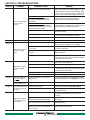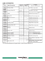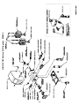
1
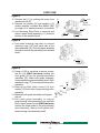
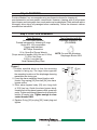
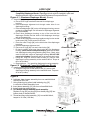
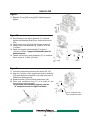
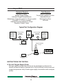
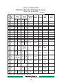
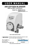
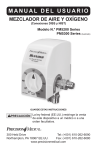
Air-Oxygen Blender Service Manual Model No. PM5200 Series PM5300 Series (shown) SAVE THESE INSTRUCTIONS 300 Held Drive Tel: (+001) 610-262-6090 Northampton, PA 18067 USA Fax: (+001) 610-262-6080 www.precisionmedical.com Contents SECTION 1: SAFETY INFORMATION - WARNINGS AND CAUTIONS..................................2 EXPLANATION OF ABBREVIATION........................................................... 3 LOW Flow Blender Diagrams (PM5300 Model).......................................... 3 HIGH Flow Blender Diagrams (PM5200 Model)........................................ 3 COMPONENT DESCRIPTIONS in Blender Diagrams................................ 4 MANIFOLD ASSEMBLY SERIVCE........................................................... 4 AIR / OXYGEN FLOW PATH INDICATION DIAGRAM................................. 6 SECTION 3: MAINTENANCE PROCEDURES, REPAIR AND CALIBRATION.................. 7 I. LOW FLOW (PM5300 Model) ................................................................. 7 Step 1: DISASSEMBLY............................................................................ 7 Step 2: CLEANING................................................................................. 10 Step 3: LOW FLOW ASSEMBLY............................................................. 10 Step 4: Test.......................................................................................... 13 Typical Test Configuration Diagram....................................................... 13 LOW Flow Operation Verification Procedure......................................... 16 II. HIGH FLOW (PM5200 Model) ............................................................... 17 Step 1: DISASSEMBLY........................................................................... 17 Step 2: CLEANING................................................................................. 20 Step 3: HIGH FLOW ASSEMBLY............................................................ 20 Step 4: Test.......................................................................................... 23 Typical Test Configuration Diagram....................................................... 23 HIGH Flow Operation Verification Procedure........................................ 26 III. INTERNATIONAL LOW / HIGH Flow Operation Verification Procedure .27 SECTION 5: BLENDER PARTS LIST............................................................................... 29 Label information........................................................................................ 30 LOW FLOW Service Kit Diagram 504933................................................. 31 HIGH FLOW Service Kit Diagram 505952................................................ 32 Air-Oxygen Blender -1- SECTION 1: SAFETY INFORMATION - WARNINGS AND CAUTIONS WARNING Indicates a potentially hazardous situation which, if not avoided, could result in death or serious injury. CAUTION Indicates a potentially hazardous situation which, if not avoided, may result in minor or moderate injury. • • • • • • • • • WARNING Disconnect the Air-Oxygen Blender from all connections prior to disassembly. Use Medical Air and Medical Oxygen when servicing to avoid contamination. The Air-Oxygen Blender should be serviced by a qualified service technician. An Oxygen Analyzer/Monitor must be used to verify oxygen concentrations. When reassembling the Blender, do not pressurize the system until the retaining screw of the Proportioning Module has been fully tightened. The Proportioning Module can be forcefully ejected by gas pressure if not sufficiently tightened. Always follow ANSI and CGA standards for Medical Gas Products, Flowmeters and Oxygen Handling. When servicing requirements of Directive 93/42/EEC concerning medical devices and all International Standards apply. (On CE marked devices ONLY) DO NOT obstruct the alarm. Oxygen Concentration Dial does not rotate 360 degrees. Rotating the dial less than 21% or over 100% oxygen will damage the Blender. Service Warning • This Service Manual is provided for your safety and to prevent damage to the Air-Oxygen Blender. • It is essential to read and understand this entire manual before attempting to service the Air-Oxygen Blender. • If you have any questions regarding the installation, setup, operation, and/or maintenance of the Air-Oxygen Blender, contact Precision Medical, Inc. CAUTION • Use recommended lubricants sparingly as lubricant may migrate to other areas • • • • • • • • and cause the Blender to malfunction. When pressurizing the Blender inlets, avoid pressure surges greater than 100 psi (6.9 bar) . Be sure all connections are tight and leak free before returning to service. Store Blender in a clean, dry area when not in use. DO NOT steam autoclave. DO NOT gas sterilize with (ETO) Ethylene Oxide. DO NOT immerse Air-Oxygen Blender into any liquid. DO NOT use if dirt or contaminants are present on or around the Blender or connecting devices. DO NOT clean with aromatic hydrocarbons. Air-Oxygen Blender -2- EXPLANATION OF ABBREVIATION FIO2 Fractional Concentration of Inspired Oxygen DISS Diameter Indexed Safety System NIST Non-Interchangeable Screw Thread lpm Liters Per Minute psi Pounds Per Square Inch Nm Newton meter LOW Flow Blender Diagrams (PM5300 Model) E A D G F B C H HIGH Flow Blender Diagrams (PM5200 Model) E D B G A F H C Air-Oxygen Blender -3- ITEM COMPONENT DESCRIPTIONS in Blender Diagrams A Primary Outlet Port A male DISS oxygen fitting with check valve that delivers flow when engaged to any controlling device, such as a flowmeter. Oxygen Inlet Fitting A female DISS or NIST oxygen fitting with one way valve that is used to connect an oxygen supply hose. Air Inlet Fitting A male DISS or NIST air fitting with one way valve that is used to connect an air supply hose. Oxygen Concentration Dial A dial used for selecting oxygen concentrations between 21%-100%. The FIO2 scale is used for reference only. This Dial does not rotate 360°. The dial starts at 21% and ends at 100%. Rear Slide Mount with dove tail. Auxiliary Bleed Collar The collar is used to engage and disengage the bleed. The bleed is necessary to maintain accurate FIO2 Concentration below 15 lpm for the High Flow and 3 lpm for the Low Flow. To activate the bleed, slide and rotate (if applicable) the knurled collar back until it contacts the cover. To deactivate the bleed, pull and rotate (if applicable) collar away from cover until it reaches a positive stop. Auxiliary Outlet Port A male DISS oxygen fitting with check valve that delivers flow when engaged to any controlling device, such as a flowmeter. This outlet is equipped with a bleed valve that allows the user to control if the bleed is ON or OFF. With the bleed in the ON position, this outlet delivers accurate oxygen concentrations in the following flows: Model Flow Range High Flow 2 – 100 lpm Low Flow 0 – 30 lpm Alarm An audible alarm that sounds due to an excessive pressure drop or deletion of either gas supply. B C D E F G H Manifold Outlet with (3) primary outlets. (Optional) The Manifold Repair Kit (Part # 506742) is not contained in the Blender Service Kit . MANIFOLD ASSEMBLY SERVICE Disassembly 1. Remove Manifold Outlet Assembly from the bottom of the Blender using a 5/32 Hex Key. 2. Unscrew (3) Primary Outlets from Manifold Block and discard. 3. Remove the Manifold Body Outlet from the bottom of the Manifold Block. a. Remove and discard the (3) O-rings. b. Remove and discard the plastic washer from the top of the Manifold Block. Assembly 1. Install (3) new Primary Outlets on the Manifold Block. (Use small amount of Blue Loctite on threads). 2. Place (3) O-rings on the Manifold Body Outlet. 3. Lubricate the hole on the Manifold Block with Krytox GPL106. 4. Insert Manifold Body Outlet through the opening of the Manifold Block. 5. Place plastic washer on top of the Manifold Body Outlet. 6. Reinstall Manifold Assembly when installing air and oxygen inlets on the Blender using a 5/32 Hex Key. Air-Oxygen Blender -4- SECTION 2: TECHNICAL DESCRIPTION The Air-0xygen Blender is a medical device used to mix Medical Air and USP Oxygen into a gas source ranging from 21% - 100% oxygen. The inlet gas connections are standard DISS or NIST for each gas. The inlets are clearly marked and labeled on the bottom of the Blender. The outlets are standard DISS male oxygen connections. The front panel of the Blender is designed has a dial that is used to set the specific FIO2 blend. The dial settings range from 21% oxygen to 100% oxygen. The Path of the Gases The supply enters through the air and oxygen inlet connectors located on the bottom of the Blender. Each inlet connector contains a particulate filter and duckbill check valves which prevent possible reverse gas flow. Diaphragm Housing Module The two gases then enter the two-stage pressure Diaphragm Housing Module. In this module, the pressures of both gas sources are equalized prior to entering the Proportioning Module. The pressure is equalized at the lower pressure. The diaphragm within the module responds to the difference in pressure and directs the movement of each check valve assembly contained within the air and oxygen chambers. The movement of each ball adjusts the amount of gas flowing through the Diaphragm Housing Module, equalizing the air and oxygen pressures to the lower pressure. Proportioning Module From the Diaphragm Housing Module the gases flow into the Proportioning Module and are mixed according to the oxygen percentage selected on the Oxygen Concentration Dial. The Proportioning Module consists of a double ended valve positioned between two valve seats. One seat controls the passage of air and the other valve seat controls the passage of oxygen into the outlet. At this point, the two gases have been blended according to the oxygen percentage selected on the Oxygen Concentration Dial. With the Oxygen Concentration Dial at the full counterclockwise position (21%), the double ended valve will completely close off the flow of oxygen, allowing only the air to flow. By adjusting the Oxygen Concentration Dial to the full clockwise position (100%), the flow of air is blocked, permitting only the flow of oxygen through the Blender outlet. Alarm and Alarm Bypass An audible alarm located on the bottom of the Blender that signals when the difference in pressure between the two inlet gasses exceeds 20 psi. When the two source gases are near equal in pressure, the alarm bypass poppet is positioned over the bypass channel, blocking the flow of both gases. The poppet will remain seated for unequal pressures up to 20 psi (1.41 kg/cm2). Once a 20 psi (1.41 kg/cm2) difference is sensed by the poppet, the higher gas pressure will overcome the spring force and pressure will overcome the spring force and pressure at its opposite end, thus creating a path for gas (air or oxygen) to flow into the alarm channel. The gas with the higher pressure will also flow directly to the Blender outlet port by passing the Balance and Proportioning Modules. The gas is also directed to the bottom of the unit to the reed alarm, thus creating and audible warning. The oxygen concentration will be that of the gas at the higher pressure. The Blender in the alarm/bypass mode will deliver the oxygen (100%) or air (21%) until the bypass mechanism resets when the source gas pressure is restored to a differential of approximately 6 psi (0.42 kg/cm2). If the Blender is set at 21% and the OXYGEN source pressure is reduced sufficiently to produce a 20 psi (1.41 kg/cm2) or greater differential, the unit will not alarm because it will continue to deliver 21% concentration according to the setting. If the control is moved slightly from the 21% setting, the alarm will sound. Similarly, if the Blender is set to deliver 100% oxygen concentration and AIR source pressure is reduced or lost, the unit will not alarm because it will continue to deliver the selected 100% concentration. The alarm will not function when there is no flow to the Blender. Air-Oxygen Blender -5- Gas Outlets The Primary and Auxiliary Outlets are DISS male adapters with check valves. AIR / OXYGEN FLOW PATH INDICATION DIAGRAM DIAPHRAGM DIAPHRAGM CHECK VALVE ALARM BYPASS VALVE PROPORTIONING VALVE BYPASS CHECK VALVE ORIFICE DUCK BILL CHECK VALVE FILTER O2 (DISS shown) AUDIBLE ALARM AIR (DISS shown) Air-Oxygen Blender -6- SECTION 3: MAINTENANCE PROCEDURES, REPAIR AND CALIBRATION I. LOW FLOW (PM5300 Model) Step 1: DISASSEMBLY Tools Required #2 Phillips Screwdriver 3 Phillips Screwdriver # 1/2 in. Open End Wrench 11/32 in. Nut Driver 5/32 in. Long Hex Key Small Retaining Ring Pliers NOTE: Photos shown of Diaphragm Blocks are Engineered Composite Blocks. Figure A 1.Rotate dial [1] to the 60 graduation. 2.Remove the two flat head screws [2] on each side of the top cover [3]. 3.Remove top cover by pulling upwards. The cover will not come off unless the dial is at the 60 graduation. [3] [2] QUANTITY - 4 [1] Figure B 4. Use a ½ in. open end wrench to unscrew and remove the air [4] and oxygen [5] inlet assemblies from bottom of the Blender. Oxygen inlet has left hand threads. 5. If manifold outlet assembly is present, unscrew the stem using a 5/32 hex key and holding the manifold outlet assembly to the bottom of the Blender. 6. Remove the four flat head screws [2] from bottom cover [6]. 7. Remove bottom cover. [6] [2] QUANTITY - 4 [4] [5] Air-Oxygen Blender -7- LOW FLOW Figure C 8.Remove dial [1] by pulling dial away from manifold block [8]. 9.Remove the primary [9] and auxiliary [10] outlets (auxiliary contains Blue Muffler [38]) by using a ½ in. open end wrench to unscrew. 10.Use Retaining Ring Pliers to unscrew and remove audio alarm assembly [11] from the bottom of the manifold block. [10] [1] [38] contained in [10] [8] [9] [11] Figure D 11.Use small retaining ring pliers to remove retaining rings [12] from each side of the alarm assembly [13]. Push the alarm assembly through to remove the assembly from manifold block. [13] [12] QUANTITY - 2 Figure E 12.Using a 11/32 in. nut driver or socket, loosen the nut [14] (ONLY two turns) holding the knob guide [15] on the proportioning valve assembly [16]. Slide knob guide assembly from proportioning valve assembly shaft. Slide resistance ring [17] from proportioning valve assembly. 13.Remove phillips head screw [18] and washer [19] from side of proportioning valve assembly. 14.Replace knob guide assembly and tighten [14] the nut. 15.Pull knob guide assembly to remove proportioning valve assembly from manifold block. Again, loosen the nut (ONLY two turns) holding the knob guide to the proportioning valve assembly, remove knob guide from proportioning valve assembly shaft. [19] [18] [16] [17] [15] Air-Oxygen Blender -8- LOW FLOW Figure F [21] 16. Remove each diaphragm housing assembly [20] from the manifold by removing the two hex socket head screws [21] on the top of each diaphragm housing with 5/32 hex key. QUANTITY - 4 NOTE: If you have received engineered composite blocks, keep the four (4) Hex Socket head screws [21] and discard the aluminum blocks you have removed. [20] QUANTITY - 2 Figure G [25] [23] 17. Using 5/32 in. long hex wrench, unscrew and remove plug [22] from the bottom of the manifold block. 18. Remove rear plug [22] from the back of the manifold block. Insert a long 5/32 hex key through rear plug opening, unscrew and remove the alarm bypass body [23], ball [24] and spring [25]. [24] [22] [22] QUANTITY - 2 NOTE: For Engineered Composite Diaphragm Blocks disregard Figure “H” and proceed to Figure “I” in the Blender maintenance process. Diaphragm blocks shall be installed in pairs and aluminum blocks shall not be mixed with engineered composite blocks. Figure H 19. Remove and discard the two O-rings [26] from the bottom of each of the diaphragm housings [27]. 20. Remove the four hex socket head screws [28] holding diaphragm housings together. 21. Remove and discard the diaphragm [29]. 22. Using Retaining Ring Pliers, remove and discard check valves [30]. Ensure inner O-ring [36] is removed from diaphragm housing. NOTE:If check valve [30] comes apart when removing it from diaphragm housing, a ¼ in. hex wrench or (#3 Phillips Screwdriver) will be needed to complete removal of the check valve from the diaphragm housing. 23. Repeat steps 19-22 for the remaining diaphragm housing assembly. 24. Make sure all O-rings have been removed from diaphragm housings and check valves. 25. Disassembly is complete. 26. Manifold block and diaphragm housing may be ultrasonically cleaned. QUANTITY -4 [28] Air-Oxygen Blender -9- Aluminum Blocks [29] QUANTITY - 2 [27] QUANTITY -2 [36] [26] QUANTITY - 4 [30] QUANTITY- 2 Step 2: CLEANING Precision Medical, Inc. recommends using an ultrasonic cleaner for cleaning all non-elastometric and non-metallic components. However, cleaning with an all-purpose liquid cleaner and rinsing with clean, warm water may be substituted. Both methods require thoroughly blow drying all passages before reassembly. Follow the ultrasonic cleaner manufacturer instruction. Step 3: LOW FLOW ASSEMBLY Tools Required Lint Free Swab (optional) Pointed instrument for removing O-rings Krytox GPL 106 or equivalent Oxygen safe lubricant #2 Phillips Screwdriver 1/2 in. Open End Torque Wrench (Torque wrench(s) capable of 60 in-lbs and 10 ft-lbs) 11/32 in. Nut Driver 5/32 in. Long Hex Key Small Retaining Ring Pliers Tools Supplied with Kit Diaphragm Alignment Tool (P/N 504838) NOTE: For use with Aluminum Diaphragm Blocks ONLY. Figure I 1.Position manifold block so that the mounting bracket is facing up. The large holes opposite the mounting locations of the diaphragm housing assemblies are facing you. 2. Cover the alarm assembly thread location with thumb. Drop spring [25] then ball [24] into alarm bypass orifice. 3. Place alarm bypass body [23] onto long shaft of 5/32 hex key. Guide the alarm bypass body, threads first into the alarm bypass orifice, screw into cavity. Tighten until alarm bypass body is flush with bottom of center hole. Tighten enough to clear center threads ONLY. 4. Replace O-ring [32] on plug [22]. Insert plug and tighten. [22] Air-Oxygen Blender - 10 - [32] [24] [23] [25] LOW FLOW NOTE: See Figure J-1 for Aluminum Diaphragm Blocks and Figure J-2 for Engineered Composite Diaphragm Blocks. Diaphragm blocks shall be installed in pairs and Aluminum Blocks shall not be mixed with Engineered Composite Blocks. Figure J-1 (Aluminum Diaphragm Blocks) (shown) 5. Assembling diaphragm housing assemblies. a. Ensure all O-rings have been removed from diaphragm housing. b. Place diaphragm alignment tool through center hole of one diaphragm housing. c. Place new diaphragm [29] on top of diaphragm housing, ensure center pin of diaphragm is in the center of diaphragm alignment tool (P/N 504838). d. Place other diaphragm housing on top of the one with the diaphragm. Ensure the inlet holes of the diaphragm housings are on the same side. e. Fasten the two diaphragm housings together using four hex socket head screws [28]. Torque screws to 60 in-lbs. f. Place four new O-rings [26] on the inlet holes of the diaphragm housings. g. Remove diaphragm alignment tool. h. Place new O-rings [36] onto each check valve [30]. i. By hand, carefully insert new check valve [30] into diaphragm housing. (Check valves are double threaded) Thread check valves into diaphragm housing using Retaining Ring Pliers. Check valve must be flush with surface of diaphragm housing. DO NOT USE power tool to tighten. Repeat this step for the second check valve. j. Using two long hex socket head screws [21] secure each diaphragm housing assembly to the manifold block. Torque to 60 in-lbs (6.8 Nm). k. Repeat steps a - i for remaining diaphragm housing assembly. [29] QUANTITY - 4 [26] Diaphragm Alignment Tool [28] QUANTITY - 4 Aluminum Blocks [21] QUANTITY - 2 [30] QUANTITY - 2 [36] QUANTITY - 2 Figure J-2 (Engineered Composite Diaphragm Blocks) 5. Installing diaphragm housing to manifold. a. Using two long hex socket head screws [21] secure each diaphragm housing assembly to the manifold block. Torque to 30 in-lbs (3.4 Nm). Figure K 6. Lubricate alarm bypass assembly bore on manifold block with Krytox GPL 106. 7. Using retaining ring pliers install retaining ring [12] in one side of alarm assembly bore. 8. Insert alarm assembly [13] into bore of manifold block. 9. Install remaining retaining ring. 10. For Models without manifold block assembly: Replace O-ring [32] on plug [22] then install plug [22] into bottom hole of manifold block. 11. Thread auxiliary outlet assembly [10] to manifold block, torque to 10 ft-lbs (13.6 Nm). [10] [12] QUANTITY - 2 [13] [32] Air-Oxygen Blender - 11 - [22] LOW FLOW Figure L 12.Thread new primary outlet assembly [37] to Manifold Block torgue to 10 ft-lbs (13.6 Nm). [37] Figure M 13.Start threads of new alarm assembly [11] by hand, tighten with Retaining Ring Pliers, ensure not to bend reed. 14.Attach bottom cover [6] using four flat head screws [2]. 15.Install new oxygen inlet assembly [5] torque to 10 ft-lbs (13.6 Nm). Oxygen inlet assembly has left handed threads. 16.Install new air inlet assembly [4], torque to 10 ft-lbs (13.6 Nm). [6] [11] [4] [5] [2] QUANTITY- 4 Figure N 17. Lubricate proportioning valve bore with Krytox GPL 106. 18. Align the (3) holes on the proportioning valve assembly [16] equal distance between the (2) plugs and push in. *Reference drawing below. [19] 19.Replace washer [19] and phillips head screw [18]. [18] 20.Place new resistance ring [17] in its place on the proportioning valve assembly. *Proportional valve assembly inserted, with [17] the “L” stamped on back for Low Flow Model. [16] plugs Air-Oxygen Blender - 12 - The “L” is stamped on the back for LOW Flow models Step 4: Test Equipment Required Tools Required Medical Air Supply Phillips Screwdriver Torque Driver capable of 10 in-lbs Medical Oxygen Supply Adjustable Wrench Calibrated Oxygen Analyzer/Monitor Calibrated Air or Oxygen flow monitor 0 to 70 lpm or greater Retaining Ring Pliers Flowmeter 0 to 70 lpm or greater Nut Driver Calibrated Pressure Gauges 0 to 100 psi Regulators Tubing / Hoses Typical Test Configuration Diagram Compressed Air Supply Adjustable 0-100 psi (0-6.89 bar) Pressure Gauge 0-100 psi (0-6.89 bar) Blender Pressure Gauge 0-100 psi (0-6.89 bar) Oxygen Supply Adjustable 0-100 psi (0-6.89 bar) Oxygen Flowmeter 0-70 lpm Condensation Trap (Recommended) Oxygen Analyzer T - Fitting Calibrated Flow Monitor Instructions for Testing A. Air and Oxygen Supply Setup Both gas supplies must be clean and dry per the specifications outlined in this manual and have the ability to generate up to 100 psi (6.89 bar) for both the air and oxygen inlet pressures. Verify air and oxygen supply concentrations with a analyzer/monitor. Air-Oxygen Blender - 13 - B. Blender Setup 1. Mount the Blender into a secured mating wall or pole bracket in an upright position. 2. Secure the air and oxygen hoses to the corresponding Blender inlets. 3. It is recommended that a condensation trap be installed in the air supply line just before the Blender air inlet. 4. Attach a flowmeter capable of 0-70 lpm to the auxiliary outlet on the Blender. 5. Attach a t-fitting to the outlet of the flowmeter. 6. Attach an Oxygen Analyzer/Monitor to the one outlet on the t-fitting. 7. Attach a calibrated Air or Oxygen Flow Monitor capable of 0-70 lpm or greater to the other outlet on the t-fitting. 8. The system is now ready for an initial performance test. C. Initial Performance Test NOTE: Before pressurizing make sure proportioning valve assembly is secure and screw is tightened. 1.Perform calibration on Oxygen Analyzer/Monitor per the manufacture’s instructions prior to testing the Blender. 2.Set Air & Oxygen pressures to 50 psi (3.45 bar) each. NOTE: Turn OFF and check for leak by watching for pressure drops on pressure gauges. 3.An initial pressure drop may occur, no further drop in pressure should occur. 4.If continued pressure drop is observed, troubleshoot by using a commercial leak detector to find source of leak and refer to Section 4: TROUBLESHOOTING for further instructions. 5.Use a lint free dry cloth to wipe Blender clean of commercial leak detector. 6.Ensure both inlet pressures are at 50 psi. 7. Replace the top cover. NOTE: DO NOT install the (4) mounting screws until the end of the Final Test, or after satisfactory completion of the Performance Check. Refer to the “OPERATING INSTRUCTIONS” in Users Manual. 8. Set flowmeter to 3-3.5 lpm. 9. Set the Blender to 60% FIO2 with Oxygen Analyzer/Monitor, this value should remain within 3.0% of original reading throughout the following test. a. Set flowmeter to 30-30.5 lpm, check concentration reading. b. Set flowmeter back to 3-3.5 lpm. c. Set air inlet pressure to 50 psi (3.45 bar) and the oxygen inlet pressure to 43 psi (2.96 bar) adjust flow to 3-3.5 lpm, check concentration reading. d. Set air inlet pressure to 43 psi (2.96 bar) and the oxygen inlet pressure to 50 psi (3.45 bar) adjust flow to 3-3.5 lpm, check concentration reading. e. If the Oxygen Analyzer/Monitor setting does not remain within 3.0% of the original reading, then replace one or both of the diaphragm block assemblies. NOTE: Diaphragm blocks shall be installed in pairs and Aluminum Blocks shall not be mixed with Engineered Composite Blocks. Air-Oxygen Blender - 14 - D. Reverse Gas Flow Procedure (Reference Operational Verification Procedure #’s 2 & 3 in Table, page 16 or 27.) 1. Disconnect the oxygen hose from the gas source. Remove all outlet connections from the Blender to ensure that there is no outlet flow. 2. Place the free end of the oxygen supply hose under water. Gradually increase the air supply pressure from 30 - 75 psi (2.07 - 5.17 bar), check for leakage past the oxygen inlet check valve. 3. Replace the Duckbill Check Valve in the oxygen inlet if bubbles indicate leakage. 4. Repeat steps 1-3 to check for leakage past the air inlet check valve. 5. Reconnect the air inlet hose and adjust both supply pressures back to standard inlet pressure. E. Setup of PROPORTIONING VALVE ASSEMBLY CALIBRATION 1. Set air and oxygen inlet pressures to 50 psi. 2. Set flow to 9 lpm. 3. Turn Adjustment Shaft counterclockwise until the Oxygen Analyzer/Monitor displays a concentration equal to that of the source air (±0.3), reference Part A in Setup. 4. Attach knob guide assembly onto adjustment shaft of proportioning valve assembly so that the knob stop rests on top of the screw. Ensure knob stop aligns with the slot in the resistance ring. 5. While applying downward pressure to the 2 screws on the knob guide assembly, attach nut to adjustment shaft using nut driver. 6. Turn knob guide fully clockwise, Oxygen Analyzer/Monitor display should be equal to concentration of the source oxygen (±0.3). 7. Turn knob guide back to 21% position to ensure no drift from original reading (±0.3). 8. Re-attach knob guide, torque nut to adjustment shaft and tighten to 10 in-lbs using a torque driver. 9. Snap in knob back into knob guide, pay close attention to the key location of the knob. 10.Set knob to 60 graduation. 11.Replace the top cover. NOTE: DO NOT install the four (4) mounting screws until the end of the Final Test. F. Final Test Complete Operation Verification Procedure as per the test table, page 16 or 27. Record test results in the test table. When Final Test is complete replace top cover and install the four (4) mounting screws into cover. NOTE: Operation Verification Procedure should be performed at least once a year. Air-Oxygen Blender - 15 - USA and CANADA ONLY LOW Flow Operation Verification Procedure (50 psi / 3.45 bar MODELS) Serial No. S E Q # Dial Set Oxygen% 1 OXYGEN PRESS ±1.0 AIR PRESS ±1.0 FLOWMETER Auxiliary Function SET TO Bleed lpm ±0.2 Target Value psi bar psi bar ANY 50 3.45 50 3.45 closed closed *2 60 75 5.17 0 0 0 closed back flow <100 ml/min *3 60 0 0 75 5.17 0 closed back flow <100 ml/min 4 21 50 3.45 50 3.45 3 open end point 5 40 50 3.45 50 3.45 3 open set point 37.0%-43.0% 6 60 50 3.45 50 3.45 3 open set point 57.0%-63.0% 7 80 50 3.45 50 3.45 3 open set point 77.0%-83.0% 8 100 50 3.45 50 3.45 3 open end point 9 60 50 3.45 50 3.45 1 open set point 57.0%-63.0% 10 60 60 4.14 67 4.62 1 open set point 57.0%-63.0% 11 60 60 4.14 50 3.45 1 open set point 57.0%-63.0% 12 60 50 3.45 Slowly Slowly reduce reduce to 30 to 2.07 3 closed Alarm ON 30.0 ± 2.0 psi 3.45 Slowly Increase until alarm shuts off 3 closed Alarm OFF 45.0 psi MAX 50 leak <2 psi / 2 MIN (±0.3) Source Value (±0.3) Source Value 13 60 14 60 Slowly Slowly Reduce Reduce to 30 to 2.07 50 3.45 3 closed Alarm ON 30.0 ± 2.0 psi 15 60 Slowly Increase until alarm shuts off 50 3.45 3 closed Alarm OFF 45.0 psi MAX 16 60 50 3.45 50 3.45 MAX closed flow rate 30.0 lpm MIN 17 60 50 3.45 MAX closed flow rate 30.0 lpm MIN 18 60 19 60 0 50 3.45 0 50 3.45 MAX closed flow rate 30.0 lpm MIN 50 3.45 MAX open flow rate 30.0 lpm MIN * Reference, Letter D. (Reverse Gas Flow Procedure) Air-Oxygen Blender - 16 - Actual Value II. HIGH FLOW (PM5200 Model) Step 1: DISASSEMBLY Tools Required #2 Phillips Screwdriver 3 Phillips Screwdriver # 1/2 in. Open End Wrench 11/32 in. Nut Driver 5/32 in. Long Hex Key Small Retaining Ring pliers NOTE: Photos shown of Diaphragm Blocks are Engineered Composite Blocks. Figure A 1. Rotate dial [1] to the 60 graduation. 2. Remove the two flat head screws [2] on each side of the top cover [3]. 3. Remove top cover by pulling upwards. The cover will not come off unless the dial is at the 60 graduation. [3] [2] QUANTITY - 4 [1] Figure B 4.Use a ½ in. open end wrench to unscrew and remove the air [4] and oxygen [5] inlet assemblies and primary [9] outlet assemblies from bottom of the Blender. Oxygen inlet has left hand threads. 5.If manifold outlet assembly is present, unscrew the stem using a 5/32 hex key and holding the manifold outlet assembly to the bottom of the Blender. 6.Remove the four flat head screws [2] from bottom cover [6]. 7.Remove bottom cover. [6] [2] QUANTITY - 4 [9] [5] [4] Air-Oxygen Blender - 17 - HIGH FLOW Figure C [1] 8.Remove dial [1] by pulling dial away from manifold block [8]. 9.Remove the auxiliary [10] outlets (auxiliary contains Blue Muffler [38]) by using a ½ in. open end wrench to unscrew. 10.Use Retaining Ring Pliers to unscrew and remove audio alarm assembly [11] from the bottom of the manifold block. [10] [38] contained in [10] [8] [11] Figure D 11.Use small retaining ring pliers to remove retaining rings [12] from each side of the alarm assembly [13]. Push the alarm assembly through to remove the assembly from manifold block. [13] [12] QUANTITY - 2 Figure E 12.Using a 11/32 in. nut driver or socket, loosen the nut [14] (ONLY two turns) holding the knob guide [15] on the proportioning valve assembly [16]. Slide knob guide assembly from proportioning valve assembly shaft. Slide resistance ring [17] from proportioning valve assembly. 13.Remove phillips head screw [18] and washer [19] from side of proportioning valve assembly. 14.Replace knob guide assembly and tighten the nut. [14] 15.Pull knob guide assembly to remove proportioning valve assembly from manifold block. Again, loosen the nut (ONLY two turns) holding the knob guide to the proportioning valve assembly, remove knob guide from proportioning valve assembly shaft. [19] [18] [16] [17] [15] Air-Oxygen Blender - 18 - HIGH FLOW Figure F [21] 16.Remove each diaphragm housing assembly [20] from the manifold by removing the two hex socket head screws [21] on the top of each diaphragm housing with 5/32 hex key. QUANTITY - 4 NOTE: If you have received engineered composite blocks, keep the four (4) Hex Socket head screws [21] and discard the aluminum blocks you have removed. [20] QUANTITY - 2 Figure G [23] 17.Using 5/32 in. long hex wrench, unscrew and remove plug [22] from the side of the manifold block. (For High Flow models with a manifold outlet assembly remove plug from left side of manifold block instead of from the bottom of the manifold [22] block.) 18.Remove rear plug [22] from the back of the manifold block. Insert a long 5/32 hex key through rear plug opening, unscrew and remove the alarm bypass body [23], ball [24] and spring [25]. [25] [24] [22] [22] QUANTITY - 2 NOTE: For Engineered Composite Diaphragm Blocks disregard Figure “H” and proceed to Figure “I” in the Blender maintenance process. Diaphragm blocks shall be installed in pairs and aluminum blocks shall not be mixed with engineered composite blocks. Figure H 19. Remove and discard the two O-rings [26] from the bottom of each of the diaphragm housings [27]. 20. Remove the four hex socket head screws [28] holding diaphragm housings together. 21. Remove and discard the diaphragm [29]. 22. Using Retaining Ring Pliers, remove and discard check valves [30]. Ensure inner O-ring [36] is removed from diaphragm housing. NOTE: If check valve [30] comes apart when removing it from diaphragm housing, a ¼ in. hex wrench or (#3 Phillips Screwdriver) will be needed to complete removal of the check valve from the diaphragm housing. 23. Repeat steps 19-22 for the remaining diaphragm housing assembly. 24. Make sure all O-rings have been removed from diaphragm housings and check valves. 25. Disassembly is complete. 26. Manifold block may be ultrasonically cleaned. Aluminum Blocks QUANTITY -4 [28] Air-Oxygen Blender - 19 - [29] QUANTITY - 2 [27] QUANTITY -2 [36] [26] QUANTITY - 4 [30] QUANTITY- 2 Step 2: CLEANING Precision Medical, Inc. Recommends using an ultrasonic cleaner for cleaning all non-elastometric components. However, cleaning with an all-purpose liquid cleaner and rinsing with clean, warm water may be substituted. Both methods require thoroughly blow drying all passages before reassembly. Follow the manufacturer’s instruction for ultrasonic cleaning. Step 3: HIGH FLOW ASSEMBLY Tools Required Lint Free Swab (optional) Pointed instrument for removing O-rings Krytox GPL 106 or equivalent Oxygen safe lubricant #2 Phillips Screwdriver 1/2 in. Open End Torque Wrench (Torque wrench(s) capable of 60 in-lbs and 10 ft-lbs) 11/32 in. Nut Driver 5/32 in. Long Hex Key Small Retaining Ring Pliers Tools Supplied Diaphragm Alignment Tool (P/N 504838) NOTE: For use with Aluminum Diaphragm Blocks ONLY. Figure I 1.Position manifold block so that the mounting bracket is facing up. The large holes opposite the mounting locations of the diaphragm housing assemblies are facing you. 2.Cover the alarm assembly thread location with thumb. Drop spring [25] then ball [24] into alarm bypass orifice. 3.Place alarm bypass body [23] onto long shaft of 5/32 hex key. Guide the alarm bypass, threads first into the alarm bypass orifice, screw into cavity. Tighten until alarm bypass is flush with bottom of center hole. Tighten enough to clear center threads ONLY. 4.Replace O-ring [32] on plug [22]. Insert plug and tighten. Air-Oxygen Blender - 20 - [22] [32] [24] [23] [25] HIGH FLOW NOTE: See Figure J-1 for Aluminum Diaphragm Blocks and Figure J-2 for Engineered Composite Diaphragm Blocks. Diaphragm blocks shall be installed in pairs and Aluminum Blocks shall not be mixed with Engineered Composite Blocks. Figure J-1 (Aluminum Diaphragm Blocks) (shown) 5. Assembling diaphragm housing assemblies. a. Ensure all O-rings have been removed from diaphragm housing. b. Place diaphragm alignment tool through center hole of one diaphragm housing. c. Place new diaphragm [29] on top of diaphragm housing, ensure center pin of diaphragm is in the center of tool. d. Place other diaphragm housing on top of the one with the diaphragm. Ensure the inlet holes of the diaphragm housings are on the same side. e. Fasten the two diaphragm housings together using four hex socket head screws [28]. Torque screws to 60 in-lbs. f. Place four new O-rings [26] on the inlet holes of the diaphragm housings. g. Remove diaphragm alignment tool. h. Place new O-rings [36] onto each check valve [30]. i. By hand, carefully insert new check valve [30] into diaphragm housing. (Check valves are double threaded). Thread into diaphragm housing using Retaining Ring Pliers, Check valve must be flush with surface of diaphragm housing. DO NOT USE power tool to tighten. Repeat this step for the second check valve. j. Using two long hex socket head screws [21] secure each diaphragm housing assembly to the manifold block. Torque to 60 in-lbs (6.8 Nm). k. Repeat steps a - i for remaining diaphragm housing assembly. [29] QUANTITY - 4 [26] Diaphragm Alignment Tool [28] QUANTITY - 4 Aluminum Blocks [21] QUANTITY - 2 [30] QUANTITY - 2 [36] QUANTITY - 2 Figure J-2 (Engineered Composite Diaphragm Blocks) 5. Installing diaphragm housing to manifold. a. Using two long hex socket head screws [21] secure each diaphragm housing assembly to the manifold block. Torque to 30 in-lbs (3.4 Nm). Figure K 6.Lubricate alarm bypass assembly bore on manifold block with Krytox GPL 106. 7.Using retaining ring pliers install retaining ring [12] in one side of alarm assembly bore. 8.Insert alarm assembly [13] into bore of manifold block. 9. Install remaining retaining ring. 10.Thread auxiliary outlet assembly [10] to manifold block, torque to 10 ft-lbs (13.6 Nm). [10] QUANTITY - 2 [12] [13] Air-Oxygen Blender - 21 - HIGH FLOW Figure L 11. Replace O-ring [32] on plug [22]. Install plug and tighten. [32] [22] Figure M 12. Start threads of new alarm assembly [11] by hand, tighten with Retaining Ring Pliers, ensure not to bend reed. 13. Attach bottom cover [6] using four flat head screws [2]. 14. Install new air inlet assembly [4], torque to 10 ft-lbs (13.6 Nm). 15. Install new oxygen inlet assembly [5] torque to 10 ft-lbs (13.6 Nm). Oxygen inlet assembly has left handed threads. 16. Thread new primary outlet assembly [37] to manifold block torque to 10 ft-lbs (13.6 Nm). [6] [11] [4] [5] [2] [37] QUANTITY- 4 Figure N 17. Lubricate proportioning valve bore with Krytox GPL 106. 18. Align the (3) holes on the proportioning valve assembly [16] equal distance between the (2) plugs and push in. *Reference drawing below. 19. Replace washer [19] and phillips head screw [18]. 20. Place new resistance ring [17] in its place on the proportioning valve assembly. *Proportional valve assembly inserted, with the “H” stamped on back for High Flow Model. [19] [18] [17] plugs [16] Air-Oxygen Blender - 22 - The “H” is stamped on the back for HIGH Flow models Step 4: Test Equipment Required Tools Required Medical Air Supply Phillips Screwdriver Torque Driver capable of 10 in-lbs Medical Oxygen Supply Adjustable Wrench Calibrated Oxygen Analyzer/Monitor Calibrated Air or Oxygen flow monitor 0 to 120 lpm or greater Retaining Ring Pliers Flowmeter 0 to 120 lpm or greater Nut Driver Calibrated Pressure Gauges 0 to 100 psi Regulators Tubing / Hoses Typical Test Configuration Diagram Compressed Air Supply Adjustable 0-100 psi (0-6.89 bar) Pressure Gauge 0-100 psi (0-6.89 bar) Blender Pressure Gauge 0-100 psi (0-6.89 bar) Oxygen Supply Adjustable 0-100 psi (0-6.89 bar) Oxygen Flowmeter 0-70 lpm Condensation Trap (Recommended) Oxygen Analyzer T - Fitting Calibrated Flow Monitor Instructions for Testing A. Air and Oxygen Supply Setup Both gas supplies must be clean and dry per the specifications outlined in this manual and have the ability to generate up to 100 psi (6.89 bar) for both the air and oxygen inlet pressures. Verify air and oxygen supply concentrations with a analyzer/ monitor. Air-Oxygen Blender - 23 - B. Blender Setup 1. Mount the Blender into a secured mating wall or pole bracket in an upright position. 2. Secure the air and oxygen hoses to the corresponding Blender inlets. 3. It is recommended that a condensation trap be installed in the air supply line just before the Blender air inlet. 4. Attach a flowmeter capable of 0-120 lpm to the auxiliary outlet on the Blender. 5. Attach a t-fitting to the outlet of the flowmeter. 6. Attach an Oxygen Analyzer/Monitor to the one outlet on the t-fitting. 7. Attach a calibrated Air or Oxygen Flow Monitor capable of 0-120 lpm or greater to the other outlet on the t-fitting. 8. The system is now ready for an initial performance test. C. Initial Performance Test NOTE: Before pressurizing make sure proportioning valve assembly is secure and screw is tightened. 1.Perform calibration on Oxygen Analyzer/Monitor per the manufacture’s instructions prior to testing the Blender. 2.Set Air & Oxygen pressures to 50 psi (3.45 bar) each. NOTE: Turn OFF and check for leak by watching for pressure drops on pressure gauges. 3.An initial pressure drop may occur, no further drop in pressure should occur. 4.If continued pressure drop is observed, troubleshoot by using a commercial leak detector to find source of leak and refer to Section 4: TROUBLESHOOTING for further instructions. 5.Use a lint free dry cloth to wipe Blender clean of commercial leak detector. 6.Ensure both inlet pressures are at 50 psi. 7. Replace the top cover. NOTE: DO NOT install the (4) mounting screws until the end of the Final Test, or after satisfactory completion of the Performance Check. Refer to the “OPERATING INSTRUCTIONS” in Users Manual. 8. Set flowmeter to 3-3.5 lpm. 9. Set the Blender to 60% FIO2 with Oxygen Analyzer/Monitor, this value should remain within 3.0% of original reading throughout the following test. a. Set flowmeter to 30-30.5 lpm, check concentration reading. b. Set flowmeter back to 3-3.5 lpm. c. Set air inlet pressure to 50 psi (3.45 bar) and the oxygen inlet pressure to 43 psi (2.96 bar) adjust flow to 3-3.5 lpm, check concentration reading. d. Set air inlet pressure to 43 psi (2.96 bar) and the oxygen inlet pressure to 50 psi (3.45 bar) adjust flow to 3-3.5 lpm, check concentration reading. e. If the Oxygen Analyzer/Monitor setting does not remain within 3.0% of the original reading, then replace one or both of the diaphragm block assemblies. NOTE: Diaphragm blocks shall be installed in pairs and Aluminum Blocks shall not be mixed with Engineered Composite Blocks. Air-Oxygen Blender - 24 - D. Reverse Gas Flow Procedure (Reference Operational Verification Procedure #’s 2 & 3 in Table, page 26 or 27.) 1. Disconnect the oxygen hose from the gas source. Remove all outlet connections from the Blender to ensure that there is no outlet flow. 2. Place the free end of the oxygen supply hose under water. Gradually increase the air supply pressure from 30 - 75 psi (2.07 - 5.17 bar), check for leakage past the oxygen inlet check valve. 3. Replace the Duckbill Check Valve in the oxygen inlet if bubbles indicate leakage. 4. Repeat steps 1-3 to check for leakage past the air inlet check valve. 5. Reconnect the air inlet hose and adjust both supply pressures back to standard inlet pressure. E. Setup of PROPORTIONING VALVE ASSEMBLY 1. Set air and oxygen inlet pressures to 50 psi (3.45 bar). 2. Set flow to 15 lpm. 3. Turn Adjustment Shaft counterclockwise until the Oxygen Analyzer/Monitor displays a concentration equal to that of the source air (±0.3), reference Part A in Setup. 4. Attach knob guide assembly onto adjustment shaft of proportioning valve assembly so that the knob stop rests on top of the screw. Ensure knob stop aligns with the slot in the resistance ring. 5. While applying downward pressure to the 2 screws on the knob guide assembly, attach nut to adjustment shaft using nut driver. 6. Turn knob guide fully clockwise, Oxygen Analyzer/Monitor display should be equal to concentration of the source oxygen (±0.3). 7. Turn knob guide back to 21% position to ensure no drift from original reading (±0.3). 8. Re-attach knob guide, torque nut to adjustment shaft and tighten to 10 in-lbs using a torque driver. 9. Snap in knob back into knob guide, pay close attention to the key location of the knob. 10.Set knob to 60 graduation. 11.Replace the top cover. NOTE: DO NOT install the four (4) mounting screws until the end of the Final Test. F. Final Test Complete Operation Verification Procedure as per the test table, page 26 or 27. Record test results in the test table. When Final Test is complete replace top cover and install the four (4) mounting screws into cover. NOTE: Operation Verification Procedure should be performed at least once a year. Air-Oxygen Blender - 25 - USA and CANADA ONLY HIGH Flow Operation Verification Procedure (50 psi / 3.45 bar MODELS) Serial No. S E Q # Dial Set Oxygen% 1 OXYGEN PRESS ±1.0 AIR PRESS ±1.0 FLOWMETER Auxiliary Function SET TO Bleed lpm ±0.2 Target Value psi bar psi bar ANY 50 3.45 50 3.45 closed closed *2 60 75 5.17 0 0 0 closed back flow <100 ml/min *3 60 0 0 75 5.17 0 closed back flow <100 ml/min 4 21 50 3.45 50 3.45 15 closed end point 5 40 50 3.45 50 3.45 15 closed set point 37.0%-43.0% 6 60 50 3.45 50 3.45 15 closed set point 57.0%-63.0% 7 80 50 3.45 50 3.45 15 closed set point 77.0%-83.0% 8 100 50 3.45 50 3.45 15 closed end point leak <2 psi / 2 MIN (±0.3) Source Value (±0.3) Source Value 9 60 50 3.45 50 3.45 1.5 open set point 57.0%-63.0% 10 60 60 4.14 67 4.62 1.5 open set point 57.0%-63.0% 11 60 60 4.14 50 3.45 1.5 open set point 57.0%-63.0% 12 60 50 3.45 Slowly Slowly reduce reduce to 31 to 2.14 15 closed Alarm ON 31.0 ± 6.0 psi 3.45 Slowly Increase until alarm shuts off 15 closed Alarm OFF 45.0 psi MAX 13 60 50 14 60 Slowly Slowly Reduce Reduce to 2.14 to 31 50 3.45 15 closed Alarm ON 31.0 ± 6.0 psi 15 60 Slowly Increase until alarm shuts off 50 3.45 15 closed Alarm OFF 45.0 psi MAX 16 60 50 3.45 50 3.45 MAX closed flow rate 120.0 lpm MIN 17 60 50 3.45 MAX closed flow rate 85.0 lpm MIN 18 60 19 60 0 50 3.45 0 50 3.45 MAX closed flow rate 85.0 lpm MIN 50 3.45 MAX open flow rate 120.0 lpm MIN * Reference, Letter D. (Reverse Gas Flow Procedure) Air-Oxygen Blender - 26 - Actual Value III. INTERNATIONAL LOW / HIGH Flow Operation Verification Procedure (60 psi / 4.14 bar MODELS) Serial No. S E Q # Dial Set Oxygen% 1 OXYGEN PRESS ±1.0 AIR PRESS ±1.0 FLOWMETER Auxiliary SET TO Bleed lpm ±0.2 Low Flow High Flow Target Value Function Low Flow low high flow flow High Flow psi bar psi bar ANY 60 4.14 60 4.14 closed closed *2 60 75 5.17 0 0 0 closed back flow <100 ml/min *3 60 0 0 75 5.17 0 closed back flow <100 ml/min 4 21 60 4.14 60 4.14 3 15 open closed end point 5 40 60 4.14 60 4.14 3 15 open closed set point 37.0%-43.0% 6 60 60 4.14 60 4.14 3 15 open closed set point 57.0%-63.0% 7 80 60 4.14 60 4.14 3 15 open closed set point 77.0%-83.0% 8 100 60 4.14 60 4.14 3 15 open closed end point 9 60 60 4.14 60 4.14 1 1.5 open set point 57.0%-63.0% 10 60 60 4.14 70 4.83 1 1.5 open set point 57.0%-63.0% 11 60 60 4.14 53 3.65 1 1.5 open set point 57.0%-63.0% 12 60 60 4.14 Slowly Slowly Lower Lower to 40 to 2.76 3 15 closed Alarm ON 13 60 60 Slowly Slowly 4.14 Increase Increase to 60 to 4.14 3 15 closed Alarm OFF 14 60 Slowly Slowly Lower Lower to 40 to 2.76 60 4.14 3 15 closed Alarm ON 15 60 Slowly Slowly Increase Increase to 60 to 4.14 60 4.14 3 15 closed Alarm OFF 16 60 60 4.14 60 4.14 MAX closed flow rate 30.0 lpm MIN 120.0 lpm MIN 17 60 60 4.14 0 0 MAX closed flow rate 30.0 lpm MIN 85.0 lpm MIN 18 60 0 0 60 4.14 MAX closed flow rate 30.0 lpm MIN 85.0 lpm MIN 19 60 60 4.14 60 4.14 MAX open flow rate 30.0 lpm MIN 120.0 lpm MIN leak * Reference, Letter D. (Reverse Gas Flow Procedure) Air-Oxygen Blender - 27 - <2 psi / 2 MIN (±0.3) Source Value (±0.3) Source Value 42.0 ±2.0 psi 31.0 ±6.0 psi 55.0 psi MAX 42.0 ±2.0 psi 31.0 ±6.0 psi 55.0 psi MAX Actual Value SECTION 4: TROUBLESHOOTING Test #’s Problem 1 Pressure drop greater than 2 psi in two minutes 2 and 3 Back flow leak 4 thru 8 Measured FIO2 values do not meet target values 9 thru 11 Measured FIO2 values do not meet target values Probable Cause Remedy Leakage from manifold caused by cut or missing o-ring or due to particulates. Check ALL manifold connections (inlets, outlets, plugs, proportioning valve, alarm poppet, etc.) with oxygen leak detector to find source of leakage; if leak is found, remove appropriate parts and clean seal area and o-rings and/or replace appropriate o-ring. Aluminum Blocks ONLY Leakage from diaphragm housing caused by damaged diaphragm or particulates. Check diaphragm housings with oxygen leak detector. If leak is found, replace with new Engineered Composite Diaphragm Blocks. Aluminum Blocks ONLY Leakage from check valve/diaphragm housing seal caused by cut or missing o-ring or due to particulates. Check check-valve/diaphragm housing seal with oxygen leak detector. If leak is found, replace with new Engineered Composite Diaphragm Blocks. Ball not sealing in the alarm bypass. Replace spring and ball in alarm bypass; ensure seal surface is clean. Auxiliary bleed is open. Close auxiliary bleed by turning and pulling knurled collar away from cover until bleed is closed. Leakage from one of the outlets. Replace outlet. Faulty inlet. Replace duckbill valve or entire inlet assembly. Outlet flow is less than 3 lpm. Adjust flowmeter to 3 lpm (Note: flow must be adjusted after each change in FIO2 setting). Proportioning valve endpoints are not set correctly. Set proportioning valve endpoints (See setup procedure in Section E). Diaphragm blocks not balancing properly. Replace with new Engineered Composite Diaphragm Blocks. Internal leakage in proportion valve. Remove proportioning valve; clean seal areas and/ or replace the two rear o-rings. If necessary, replace proportioning valve assembly. Bleed not open. Open bleed by turning and pushing the knurled collar until it contacts the cover. Blockage in bleed holes. Replace auxiliary outlet. Internal leak in proportioning valve. Remove proportioning valve; clean seal areas and/ or replace the two rear o-rings. If necessary, replace proportioning valve assembly. Flow not set to 1 lpm. Adjust flow to 1 lpm. Diaphragm blocks not balancing properly. Replace diaphragm block. 12 and 14 Alarm not audible and gas is not exiting the alarm vent Pressure differential not sufficient to trigger alarm. Ensure supply pressures are set properly to achieve differential (Low Flow: 18 to 22; High Flow: 13 to 25). Alarm not audible and gas is exiting the alarm vent Faulty alarm. Replace alarm. (See Figure C & M) Faulty alarm assembly. Replace alarm assembly. (See Figure D & K) Ball not sealing in the alarm bypass. Replace spring and ball in alarm bypass; ensure seal surface is clean. Gas inlets are restricted. Check appropriate gas inlet(s) for restriction in gas pathway; replace duckbill or entire inlet as necessary. High flow model only: low flow inlets installed in place of high-flow inlets. Confirm that high-flow inlets are installed; replace as necessary. 13 and 15 Alarm does not turn off after balancing supply pressures 16 thru 19 Measured flow values do not meet minimum target values Alarm bypass is threaded too far into manifold Replace ball and spring (see Figure I for proper block (only applicable to tests 17 and 18). assembly method). High flow models only: wrong ball in alarm bypass block (only applicable to tests 17 and 18). - 28 - Confirm that correct ball is installed in alarm bypass; replace as necessary. Air-Oxygen Blender SECTION 5: BLENDER PARTS LIST Part # 504562 504720 504718 504719 504830 505045 504537 505046 504605 504546 504741 506084 505994 504566 504536 504530 set 504938 505030 504664 set 504557 set 505009 504561 504684 506327 504526 506745 506748 504122 504686 1013 504997 504744 506743 506744 505407 504932 506742 Description CONTROL KNOB (dial) FLAT HEAD SCREW TOP COVER BOTTOM COVER AIR INLET ASSEMBLY Low Flow PM5300 High Flow PM5200 OXYGEN INLET Assembly MANIFOLD BLOCK ASSEMBLY PRIMARY OUTLET Assembly EASYOFF AUXILIARY ASSEMBLY AUDIO ALARM ASSEMBLY RING RETAINING MAIN ALARM Assembly GUIDE KNOB Assembly PROPORTIONING VALVE Assembly RESISTANCE RING pAN HEAD SCREW FLAT WASHER MOLDED DIAPHRAGM HOUSING ASSEMBLY HEX SOCKET HEAD SCREW BYPASS ALARM SERVICE KIT O-RING, #008,SILICONE,70 DUROMETER O-RING, #013,SILICONE,70 DUROMETER O-RING,#006,BUNA-N,70 DUROmeter O-RING,10MM X 1.5MM,VITON,75 DUROmeter outlet cap flow path plug assembly bypass alarm body assembly (Incuded in 506748 and 506745: Bypass Alarm Service Kit) Service Kit MANIFOLD SERVICE KIT (Sold Separately) NIST Blenders ONLY 505534 505535 506498 506499 505498 505496 505497 505495 SERVICE KIT - PM5200NIST SERVICE KIT - PM5300NIST Service Kit inlets & alarm,1year - pm5200nist Service Kit inlets & alarm,1year - pm5300nist NIST AIR INLET ASSEMBLY NIST OXYGEN INLET ASSEMBLY - 29 - Air-Oxygen Blender Label information Part # *504679 504680 505302 505494 504844 504675 505301 505304 504678 504672 504673 504681 504682 505300 505303 504676 504677 505268 505269 505426 *505427 504674 504748 505143 505144 504879 Label Description Primary Outlet Primary Outlet, CE Scale Scale, CE Top Face Auxiliary Outlet Auxiliary Outlet, CE Bottom Bottom, CE Outlet, Auxiliary Outlet, Primary Model#, Caution Serial # Year of mfr / CE Low Flow PM5300 High Flow PM5200 Location (Blender / dial facing you) Left Side on top cover Left Side on top cover Bottom Front on top cover Bottom Front on top cover Top Back on top cover Top Front on top cover Right Side on top cover Right Side on top cover Bottom Cover Bottom Cover Front of manifold by outlet(s) Front of manifold by outlet(s) Top Back on top cover Bottom Back on rear slide mount Bottom Back on top cover under Model#, Caution label *For customized Blenders with special labels, contact Precision Medical, Inc. - 30 - Air-Oxygen Blender Air-Oxygen Blender - 31 - LOW FLOW Service Kit Diagram 504933 Air-Oxygen Blender - 32 - HIGH FLOW Service Kit Diagram 505952 Precision Medical, Inc. 300 Held Drive Northampton, PA 18067 USA Toll Free Tel: 800-272-7285 Toll Free Fax: 800-353-1240 Tel:(+001) 610-262-6090 Fax:(+001) 610-262-6080 504827 Rev8 090811 Printed in USA