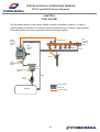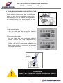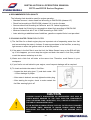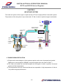
1
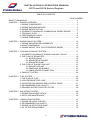
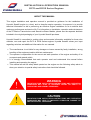
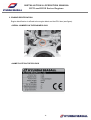
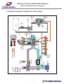
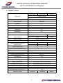
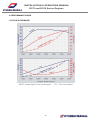
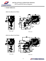
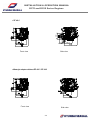
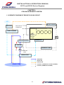
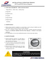
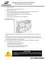
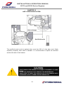
INSTALLATION & OPERATION MANUAL
D170 and D150 Series Engines
TABLE OF CONTENTS
PAGE NUMBER
ABOUT THIS MANUAL ………………………………………………………………….....…. 3
CHAPTER 1 ENGINE OVERVIEW ……………………………………………………………… 4
1. ENGINE COMPONENTS ……………………………………………………… 4
2. ENGINE SUSPENSION EYES ……………………………………………….. 5
3. ENGINE IDENTIFICATION ……………………………………………………. 6
4. SCHEMATIC DIAGRAM OF COMMON RAIL DIESEL ENGINE …….. 7
5. TECHNICAL DATA ……………………………………………...………… 8
6. PERFORMANCE CURVE ………………………………………………… 9
7. ENGINE DIMENSIONS ………………………………………………...… 12
CHAPTER 2 ENGINE MOUNT SYSTEM .………………………………………………..
1. ENGINE MOUNTING REQUIREMENTS ……………………………….
2. MOUNT DIMENSIONS ……………………………………………………
3. ENGINE MOUNT TOOL FOR STERNDRIVE MODEL ………………..
15
15
15
16
CHAPTER 3 COOLING & EXHAUST SYSTEM ………………………………………….
1. SCHEMATIC DIAGRAM OF ENGINE COOLING CIRCUIT ……..…...
2. THE FLOW OF SEAWATER …………………………………………..…
2.1 WATER PICKUP ………………………………………………..
2.2 SEAWATER STRAINER ……………………………………….
2.3 SEAWATER PUMP ………………………………………..……
3. THE FLOW OF ENGINE COOLANT ………………………………..…...
3.1 ENGINE COOLANT …………………………………………..…
3.2 REMOVING AIR BUBBLE ……………………………………...
3.3 CABIN HEATER CONNECTION ………………………………
4. EXHAUST SYSTEM …………………………………………………….....
17
17
18
18
18
19
21
21
23
23
24
CHAPTER 4 FUEL SYSTEM ……………………………………………………………….. 25
1. THE FLOW OF FUEL …………………………..…………………………. 26
2. LOW PRESSURE FUEL LINE …………………....……………………… 26
3. ACCELERATION SENSOR AND CONTROL LEVER …………………. 27
4. RECOMMENDED FUEL QUALITY ………………....…………………… 28
5. DRAINING WATER FROM FUEL FILTER ……………………………… 28
CHAPTER 5 AIR INTAKE SYSTEM ……………………………………………………….. 29
1. ENGINE ROOM VENTILATION ………………………………………….. 29
2. AIR FILTER MAINTENANCE …………………………..………………… 30
CHAPTER 6 LUBRICATION SYSTEM ……………………………………………………
1. ENGINE OIL LEVEL CHECKS ……………………….…………………
2. RECOMMENDED OIL QUALITY …………………….....………………
3. ENGINE OIL EXTACTION PUMP ………………………..…………….
4. OIL FILTER REPLACEMENT …………………………….…………….
-1-
31
31
31
32
32
INSTALLATION & OPERATION MANUAL
D170 and D150 Series Engines
TABLE OF CONTENTS
PAGE NUMBER
CHAPTER 7 ELECTRICAL SYSTEM …………………………………………………….
1. BATTERY CABLE CONNECTIONS ……………………………...…….
2. BATTERY CHECKS ………………………………………………..…….
3. FUSE AND RELAY …………………………………………………...…..
33
33
34
35
CHAPTER 8 INSTRUMENT SYSTEM ……………………...………………………........
1. INSTRUMENTS CONNECTION …………..……………………………
2. CUT-OUT FOR GAUGE ……………………...………………………….
3. CUT-OUT FOR EOI SYSTEM …………………..………………………
37
37
39
39
CHAPTER 9 EOI SYSTEM …………………………………………..…………………….
1. OVERVIEW OF EOI SYSTEM ……………………..……………………
1.1 INFORMATION LCD ITEM ……………………...…………………..
1.2 SWITCHES ………………………………………......……………….
1.3 ALARM LAMPS ………………………………………..……………..
2. EOI CONNECTIONS ………………………………………......………….
3. EOI PIN ASSIGNMENT …………..……………………………......…….
4. NEUTRAL SWITCH AND DUAL EOI CONNECTION …………..…….
5. ALARM AND DTC(DIAGNOSIS TROUBLE CODE) ……………......…
5.1 ALARM AND DTC(DIAGNOSIS TROUBLE CODE) ……………..
5.2 DTC(DIAGNOSIS TROUBLE CODE) LIST……….. ……………..
40
40
40
41
41
42
43
45
46
46
49
CHAPTER 10 ANTI CORROSION SYSTEM ……………………………………………... 54
CHAPTER 11 ENGINE OPERATION …………………………………………..…………..
1. ENGINE ON/OFF …………………………………………………..………
2. EMERGENCY STOP …………………..…………………………….…….
3. WINTER OPERATION AND STORAGE ……………………….………..
55
55
56
56
CHAPTER 12 ENGINE STORAGE …………………………………………………..……… 57
CHAPTER 13 MAINTENANCE ………………………………………………………..……
1. PREDELIVERY INSPECTION LIST……………………………………..
2. MAINTENANCE SCHEDULE ………………………………………..…..
3. MAINTENANCE LOG …………………………………………………..…
58
58
59
60
CHAPTER 14 TROUBLESHOOTING GUIDE ………………………………………….....
61
CHAPTER 15 WARRANTY …………………………………………………………………. 63
WARRANTY REGISTRATION CARD ………………………………….… 66
-2-
INSTALLATION & OPERATION MANUAL
D170 and D150 Series Engines
ABOUT THIS MANUAL
This engine installation and operation manual is provided as guidance for the installation of
Hyundai SeasAll engine to a boat, and to describe engine operation. Its purpose is to provide
technical information to aid in performing an effective engine installation so as to achieve both
maximum performance and service life. For information on installation, operation and maintenance
of the ZF Marine Transmissions and Sterndrive Bravo Models, please see the separate booklets
included in the original packaging of your Hyundai SeasAll purchase.
Hyundai SeasAll is committed to making clear and accurate information available for those who
maintain, own and repair the D170 & D150 Series engines. Hyundai SeasAll values your input
regarding revisions and additional information for our manuals.
§ The manufacturer is not liable for any damages or losses caused by faulty installation, wrong
handling of the equipment and/or deficient maintenance.
§ The operator is responsible for the correct and safe operation of the engine and safety of its
occupants and general public.
§ It is strongly recommended that each operator read and understand this manual before
installing and operating the engine.
§ This manual as well as safety labels posted on the engine use the following safety alerts to
draw your attention to special safety instructions that should be followed.
!
!
WARNING
WARNING
DEVIATION
DEVIATION FROM
FROM INSTALLATION
INSTALLATION INSTRUCTIONS
INSTRUCTIONS AND
AND OPERATION
OPERATION
GUIDELINES
MAY
LEAD
TO
PERSONAL
INJURY
GUIDELINES MAY LEAD TO PERSONAL INJURY OR
OR DEATH
DEATH TO
TO
OPERATORS
AND
NEARBY
PERSONNEL.
OPERATORS AND NEARBY PERSONNEL.
CAUTION
CAUTION
DEVIATION
DEVIATION FROM
FROM INSTALLATION
INSTALLATION INSTRUCTIONS
INSTRUCTIONS AND
AND OPERATION
OPERATION
GUIDELINES
GUIDELINES MAY
MAY LEAD
LEAD TO
TO IMPROPER
IMPROPER OPERATION,
OPERATION, DAMAGE
DAMAGE OR
OR
DESTRUCTION
OF
THE
ENGINE.
DESTRUCTION OF THE ENGINE.
-3-
INSTALLATION & OPERATION MANUAL
D170 and D150 Series Engines
CHAPTER 1
ENGINE OVERVIEW
1. ENGINE COMPONENTS
1.
2.
3.
4.
5.
6.
ECU Box
Coolant Expansion Tank
Engine Oil Cap
Engine Oil Filter
P/S Oil Cooler
Fuel Pump
1.
2.
3.
4.
5.
6.
VGT
Exhaust Elbow
Bell Housing
Air Filter
Engine Oil Exchange Button
Engine Emergency Stop Button
7. Engine Oil Gauge
8. Acceleration Lever Sensor
9. Seawater Pump
10. Intercooler
11. Heat Exchanger
12. Alternator
7. VGT Controller
8. Shift Plate
9. Oil Extraction Pump
10. Injector
11. PRV
12. BPS & IATS
-4-
INSTALLATION & OPERATION MANUAL
D170 and D150 Series Engines
2. ENGINE SUSPENSION EYES
1) To lift the engine, first remove the engine cover. You will find two engine eyes (see
figure)
2) To avoid engine damage, take care that engine lift chains or belts do not hit or
touch surrounding parts during engine lifting.
-5-
INSTALLATION & OPERATION MANUAL
D170 and D150 Series Engines
3. ENGINE IDENTIFICATION
Engine identification is affixed to the engine block and the ECU box (see figure).
§ SERIAL NUMBER ON THE ENGINE BLOCK
§ NAME PLATE ON THE ECU BOX
-6-
INSTALLATION & OPERATION MANUAL
D170 and D150 Series Engines
4. SCHEMATIC DIAGRAM OF COMMON RAIL DIESEL ENGINE
Pump
pressure
regulator
valve
Fuel
temperature
sensor
Water sensor
in fuel
Feed
pump
return
High
pressure
pump
Fuel tank
Main
fuel
filter
Glow
plug
Injector
Coolant
temperature
sensor
return
Rail pressure sensor
Common rail
return
Crankshaft
position
sensor
Cam Position
Sensor
Sensor
Actuator
Rail
pressure
regulator
valve
return
Air
filter
Air temp.
sensor
Vacuum
modulator
VGT actuator
Intercooler
Boost pressure & air
temp sensor
Fuel feed (low)
Fuel return
Fuel feed (high)
VGT
Accel position
sensor
-7ECU
INSTALLATION & OPERATION MANUAL
D170 and D150 Series Engines
5. TECHNICAL DATA
D170 / 150S
Engine type
D170 / 150P
D170J
4-stroke, 4-valve
After-cooled, direct-injection, water cooling
Output ps (kW)
170ps (125) / 150ps (110)
rpm at full load
3800/3200
Cylinders
I-4
Ignition sequence
1-3-4-2
Displacement [cm3]
2188
Bore [mm]
87
Stroke [mm]
92
Compression ratio
17.3 : 1
Max. torque [kgm]
@ speed [rpm]
36
34
2000
3500
Injection system
Common rail direct injection
Diesel fuel
at least CN 51 as per DIN EN 590
Intake air pressure (abs. bar)
@ speed [rpm]
2.5
2.5
2.5
3800/3200
3800/3200
3800
Coolant quantity (liter)
6.5
Coolant cap opening pressure (bar)
1.1
Engine oil (liter)
6
Engine oil pressure (bar)
2~3 at 1800rpm, 100 ℃(oil temp.)
Exhaust gas pressure (kPa)
Max. 45
Alternator [A]
120
Engine diagnosis
Yes
Weight (kg)
261
Battery capacity (AH)
12V, at least 150AH recommended
Thermostat opening temp. (℃)
85 (starting to open), 95 (fully open)
Idle rpm warmed up (rev/min)
700
Permissible eng. oil temp (℃)
135
Permissible eng. coolant temp (℃)
104
Propulsion system
Sterndrive
-8-
Shaftdrive
Waterjet
INSTALLATION & OPERATION MANUAL
D170 and D150 Series Engines
6. PERFORMANCE CURVE
§ D170S & D170P MODEL
*BSFC : Brake Specific Fuel Consumption
-9-
*FC : Fuel Consumption
INSTALLATION & OPERATION MANUAL
D170 and D150 Series Engines
§ D170J MODEL
*BSFC : Brake Specific Fuel Consumption
-10-
*FC : Fuel Consumption
INSTALLATION & OPERATION MANUAL
D170 and D150 Series Engines
§ D150S & D150P MODEL
*BSFC : Brake Specific Fuel Consumption
-11-
*FC : Fuel Consumption
INSTALLATION & OPERATION MANUAL
D170 and D150 Series Engines
7. ENGINE DIMENSIONS
§ MerCruiser Bravo One X Diesel
Front view
Side view
§ MerCruiser Bravo Two X Diesel
Front view
Side view
-12-
INSTALLATION & OPERATION MANUAL
D170 and D150 Series Engines
§ MerCruiser Bravo Three X Diesel
Front view
Side view
§ ZF 45 A
Side view
Front view
-13-
INSTALLATION & OPERATION MANUAL
D170 and D150 Series Engines
§ ZF 45 C
Front view
Side view
§ Waterjet adapter without ZF 45C / ZF 63C
Front view
Side view
-14-
INSTALLATION & OPERATION MANUAL
D170 and D150 Series Engines
CHAPTER 2
ENGINE MOUNT SYSTEM
1. ENGINE MOUNTING REQUIRMENTS
§ The mount must be strong enough to carry the loads applied by the weight and power of the
engine. It also must be stiff enough that the engine does not sag or move too much when
power is applied.
§ The mount must position the engine at the correct height and angle so that the engine’s
thrust line suits the boat.
2. ENGINE MOUNT DIMENSIONS
!
CAUTION
CAUTION
USE
USE ONLY
ONLY THE
THE ORIGINAL
ORIGINAL HYUNDAI
HYUNDAI SeasAll
SeasAll MOUNTINGS
MOUNTINGS THAT
THAT WERE
WERE
SUPPLIED
SUPPLIEDWITH
WITHTHE
THEINITIAL
INITIALPURCHASE.
PURCHASE.
AFTER
AFTER INSTALLATION
INSTALLATION AND
AND ALIGNMENT
ALIGNMENT OF
OF THE
THE ENGINE,
ENGINE, MAKE
MAKE SURE
SURE
THAT
NO
RESIDUAL
TENSION
EXISTS
IN
THE
DRIVETRAIN.
THAT NO RESIDUAL TENSION EXISTS IN THE DRIVETRAIN.
-15-
INSTALLATION & OPERATION MANUAL
D170 and D150 Series Engines
3. ENGINE MOUNT TOOL FOR STERNDRIVE MODEL
Mount hole for S250 and S220 model
Mount hole for D170 and D150 model
CAUTION
CAUTION
!
FOR
FOR INFORMATION
INFORMATION ON
ON INSTALLATION
INSTALLATION OF
OF THE
THE STERNDRIVE
STERNDRIVE BRAVO
BRAVO
MODELS,
PLEASE
SEE
THE
SEPARATE
BOOKLETS
INCLUDED
IN
MODELS, PLEASE SEE THE SEPARATE BOOKLETS INCLUDED IN THE
THE
ORIGINAL
ORIGINAL PACKAGING
PACKAGING OF
OF YOUR
YOUR HYUNDAI
HYUNDAI SeasAll
SeasAll PURCHASE.
PURCHASE. IF
IF IN
IN
DOUBT
DOUBT ABOUT
ABOUT ENGINE
ENGINE INSTALLATION,
INSTALLATION, PLEASE
PLEASE CONTACT
CONTACT YOUR
YOUR
NEAREST
NEARESTHYUNDAI
HYUNDAISeasAll
SeasAllDEALER.
DEALER.
-16-
INSTALLATION & OPERATION MANUAL
D170 and D150 Series Engines
CHAPTER 3
COOLING & EXHAUST SYSTEM
1. SCHEMATIC DIAGRAM OF ENGINE COOLING CIRCUIT
AIR
ENG.OIL COOLER
AIR FILTER
CABIN HEATER
CONNECTOR
TURBO CHARGER
Pc
COOLANT
PUMP
IN-MANIFOLD
HEAT EXCHANGER
THERMOSTAT
OIL COOLER
EXPANSION TANK
OIL
Ps
SEA WATER
PUMP
INTERCOOLER
SEAWATER
INTAKE AIR
EXHAUST AIR
COOLANT ( THERMOSTAT CLOSED & OPENED )
SEAWATER
COOLANT (THERMOSTAT OPENED )
-17-
INSTALLATION & OPERATION MANUAL
D170 and D150 Series Engines
2. THE FLOW OF SEAWATER – OPEN COOLING CIRCUIT
Water strainer ← Water valve ← Water pickup
↓
① Intercooler
↓
② Seawater pump
↓
③ Oil cooler
↓
④ Heat exchange
↓
⑤ Exhaust elbow
↓
Sea water
2.1 WATER PICKUP
1) Water pickup should be installed in an area where it won’t pickup air bubbles and will
access fresh water during the duration of engine operation.
2) For use in sterndrive models, please see the section “Installing Sterndrive Seawater
Pickup” of the BRAVO MODELS INSTALLATION MANUAL,
included in the original
packaging.
3) For further safety, you can use an additional transom or bottom type water pickup.
2.2 WATER STRAINER
1) Strainer should be located in an area where it
will be easily accessible for periodic seawater
flow inspection and cleaning.
2) The size of strainer must be of sufficient capacity
to pass the seawater (a flow rate over 150 liters
per minute flow rate).
3) Strainer must be installed after water inlet valve
in order to allow user to shut off seawater when
cleaning strainer filter.
!
CAUTION
CAUTION
IF
IFASSEMBLY
ASSEMBLYIS
ISNOT
NOTCONDUCTED
CONDUCTEDPROPERLY,
PROPERLY,AIR
AIRCAN
CANBE
BESUCKED
SUCKED
IN,
IN, DISTURBING
DISTURBING THE
THE VACUUM
VACUUM PROCESS.
PROCESS. THIS
THIS CAN
CAN CAUSE
CAUSE THE
THE
ENGINE
ENGINETO
TOOVERHEAT.
OVERHEAT.
-18-
INSTALLATION & OPERATION MANUAL
D170 and D150 Series Engines
4) To clean strainer filter,
• Stop the engine and close the water valve
• Remove the filter cap
• Remove the filter element, flush it thoroughly with clean water or compressed air
• Insert the cleaned filter element and screw the filter cap
• Check the cap and the gasket for correct seating and sealing
• Open the water valve
• Start the engine and check if there is water leakage
2.3 SEAWATER PUMP
1) The internal diameter of hoses from water pick up to seawater pump inlet should be
40mm.
2) The cross section of hose may shrink due to inlet pressure drop. Therefore, the hose from
water pickup in the boat’s hull to seawater pump inlet should be as short as possible and
must be made of steel wire reinforced material.
3) The seawater pump impeller must be checked periodically and replaced if necessary.
4) To check seawater pump and impeller :
• Stop the engine and close the water valve
• Remove the impeller housing cover
• Remove the impeller from inside the seawater pump
• Check the condition of impeller and bushing
!
CAUTION
CAUTION
IF
IFASSEMBLY
ASSEMBLYIS
ISNOT
NOTCONDUCTED
CONDUCTEDPROPERLY,
PROPERLY,AIR
AIRCAN
CANBE
BESUCKED
SUCKEDIN,
IN,
DISTURBING
THE
VACUUM
PROCESS.
THIS
CAN
CAUSE
THE
DISTURBING THE VACUUM PROCESS. THIS CAN CAUSE THE ENGINE
ENGINE
TO
TOOVERHEAT.
OVERHEAT.
-19-
INSTALLATION & OPERATION MANUAL
D170 and D150 Series Engines
• Apply soapy water to impeller when assembling, and reassemble towards
rotation direction
• Replace of the O-ring on the impeller housing cover
• Open the water valve
• Start the engine and check if there is water leakage
!
!
!
CAUTION
CAUTION
DO
DO NOT
NOT RUN
RUN THE
THE ENGINE
ENGINE WITHOUT
WITHOUT SEAWATER.
SEAWATER. THE
THE SEAWATER
SEAWATER
PUMP
IMPELLER
WILL
BE
DAMAGED.
BEFORE
PUMP IMPELLER WILL BE DAMAGED. BEFORE STARTING
STARTING THE
THE
ENGINE,
ENGINE,BE
BESURE
SURETO
TOSUPPLY
SUPPLYSEAWATER
SEAWATERTO
TOTHE
THEPASSAGES.
PASSAGES.
CAUTION
CAUTION
IMPELLER
IMPELLERDAMAGE
DAMAGEMAY
MAYOCCUR
OCCURIF
IF APPROPRIATE
APPROPRIATE TOOLS
TOOLS ARE
ARE NOT
NOT
USED
WHEN
REMOVING
THE
IMPELLER.
MAKE
SURE
TO
CHECK
USED WHEN REMOVING THE IMPELLER. MAKE SURE TO CHECK OORING
RINGCONDITION
CONDITIONAFTER
AFTERSEAWATER
SEAWATERPUMP
PUMPREASSEMBLY.
REASSEMBLY.
CAUTION
CAUTION
DO
DO NOT
NOT INSTALL
INSTALL ADDITIONAL
ADDITIONAL DEVICES
DEVICES WHICH
WHICH COULD
COULD OBSTRUCT
OBSTRUCT
THE
FLOW
OF
SEAWATER.
THIS
CAN
CAUSE
THE
ENGINE
THE FLOW OF SEAWATER. THIS CAN CAUSE THE ENGINE TO
TO
OVERHEAT.
OVERHEAT.
-20-
INSTALLATION & OPERATION MANUAL
D170 and D150 Series Engines
3. THE FLOW OF ENGINE COOLANT – CLOSED COOLING CIRCUIT
§ THERMOSTAT CLOSED CONDITION
① Coolant engine outlet
↓
Thermostat closed (opening temp 85℃)
↓
② Engine coolant circulation internally
§ THERMOSTAT OPENED CONDITION
① Coolant engine outlet
④ Expansion tank
② Heat exchanger
↓
Thermostat opened (opening temp 85℃)
↓
③ Coolant engine inlet
3.1 ENGINE COOLANT
1) The high-pressure cooling system has a reservoir
filled with year-round antifreeze coolant. The
reservoir is filled at the factory.
2) The coolant level should be between MAX and MIN
marks on the side of the coolant reservoir when the
engine is cool.
-21-
INSTALLATION & OPERATION MANUAL
D170 and D150 Series Engines
3) If the coolant level is low, add enough specified coolant to provide protection against
freezing and corrosion. Bring the level to MAX, but do not overfill.
4) If frequent additions are required, see an authorized dealer for a cooling system
inspection.
5) Use only soft (demineralized) water in the coolant mixture.
6) The engine has aluminum engine parts and must be protected by an ethylene-glycolbased coolant to prevent corrosion and freezing.
7) DO NOT USE alcohol or methanol coolant or mix them with the specified coolant.
8) DO NOT USE a solution that contains more than 60% antifreeze or less than 35%
antifreeze, which would reduce the effectiveness of the solution.
9) For mixture percentages, refer to the following table:
10) In order to drain engine coolant, please remove clamp and hose① from the heat
exchanger
11) when reassemble hose, please exchange old clamp with new one.
HEAT EXCHANGER
Anode & Drain plug (water)
Engine coolant hose
-22-
INSTALLATION & OPERATION MANUAL
D170 and D150 Series Engines
3.2 REMOVING AIR BUBBLES IN COOLANT LINE
1) Start the engine and warm it up at a low rpm (up to thermostat opening)
2) Next, stop the engine and allow the engine to cool enough, and then open the cap of the
expansion tank carefully.
*NOTE: Never open the cap when the engine is hot. Doing so may cause scalding.
3) Refill with coolant if needed.
4) Recap the expansion tank.
5) Please check the level of expansion tank regularly while driving.
3.3 CABIN HEATER CONNECTION
1) In order to use cabin heater, an extra coolant circulation pump is needed.
2) After connecting cabin heater lines, engine coolant must be refilled and checked.
3) Please check coolant flow direction, as shown in figure.
4) If in doubt, please contact your nearest Hyundai SeasAll dealer.
To heater
From heater
* Outer diameter of line is Ø19.3 mm
!
WARNING
WARNING
NEVER
NEVER OPEN
OPEN THE
THE EXPANSION
EXPANSION TANK
TANK CAP
CAP WHEN
WHEN THE
THE ENGINE
ENGINE IS
IS
OPERATING
OR
HOT.
IT
MAY
CAUSE
ENGINE
DAMAGE
AND
OPERATING OR HOT. IT MAY CAUSE ENGINE DAMAGE AND COULD
COULD
RESULT
RESULTIN
INSERIOUS
SERIOUSPERSONAL
PERSONALINJURY.
INJURY.
-23-
INSTALLATION & OPERATION MANUAL
D170 and D150 Series Engines
4. EXHAUST SYSTEM
1) Your Hyundai SeasAll engine’s exhaust system consists of a coolant-cooled exhaust
manifold and a seawater-cooled exhaust elbow (water injected wet exhaust system).
2) The vessel’s exhaust pipe line should not be made too long or to bend. The maximum
back pressure of the exhaust gas should be under 350 mbar.
3) Make sure that the shortest height between bottom of the exhaust elbow and the
center of the crank axis is 30cm.
4) If the distance between the bottom of the exhaust elbow and the waterline is less than
15cm, or if the waterline is above the water injection point, there is a risk of flowing
back (siphoning by engine stopping and outside seawater entering through the
transom exhaust hole).
5) In order to avoid this risk, an air ventilation unit and exhaust riser are needed. If in
doubt about exhaust system installation, please contact your nearest Hyundai SeasAll
dealer.
Shift plate mount
hole
Exhaust elbow bottom
×
150mm
304mm
Sea waterline ×
Screw plug for sea water extraction
Screw plug for exhaust gas extraction
× Center of crank axis
!
CAUTION
CAUTION
IF
IF IN
IN DOUBT
DOUBT ABOUT
ABOUT EXHAUST
EXHAUST SYSTEM
SYSTEM INSTALLATION,
INSTALLATION, PLEASE
PLEASE
CONTACT
YOUR
NEAREST
HYUNDAI
SeasAll
CONTACT YOUR NEAREST HYUNDAI SeasAllDEALER.
DEALER.
-24-
INSTALLATION & OPERATION MANUAL
D170 and D150 Series Engines
CHAPTER 4
FUEL SYSTEM
The fuel supply system of this engine is diesel common rail direction injection. In order to
optimize engine combustion, its maximum injection pressure is up to 1600 bar. Multi-injection
is possible thanks to the quick response of the solenoid type injector.
Pump
pressure
regulator
valve
Rail
Pressure
regulator
valve
Common rail
return
High
Pressure
pump
Rail Pressure Sensor
return
Injector
Fuel
Temperature
Sensor
Water in Fuel
Sensor
Fuel
filter
return
Feed
Pump
Fuel feed (low)
Fuel return
Fuel tank
Fuel feed (high)
-25-
return
INSTALLATION & OPERATION MANUAL
D170 and D150 Series Engines
1. THE FLOW OF FUEL
Fuel tank
↓
Auxiliary fuel filter
↓
① Fuel pump (low pressure)
↓
② Fuel filter with water detection sensor
↓
③ High pressure pump
↓
④ Common rail
↓
⑤ Injector or return to fuel tank
Fuel return
Fuel feeding
2. LOW PRESSURE FUEL LINE
① Return line to fuel tank ( engine out )
② Feeding line from main fuel filter to high pressure pump
③ Feeding line from fuel tank to electric feed pump (low pressure pump)
※ The internal diameter of all fuel lines must be at least 8 mm.
-26-
INSTALLATION & OPERATION MANUAL
D170 and D150 Series Engines
3. ACCELERATION SENSOR AND CONTROL LEVER
65 mm
When installing control lever cable to acceleration
sensor, be sure that the acceleration sensor lever is
fully released to the idle position and fully pulled to
the full-load position. The swing distance of lever
between idle and full-load position is 65mm.
The procedures for control lever installation
1) Idle position setting
You can make sure that the position value(%)
should indicate 0% at neutral condition.
2) Full load position setting
You can make sure that the position value(%)
should
indicate
full
load
range(90~99.2%)
adequately at fully forward lever condition. If not
fulfilled, you need to disassemble and adjust the
base neutral position of control lever by moving it
to the rear until fulfilled.
Base neutral
position
F
!
R
CAUTION
CAUTION
YOU
YOU SHOULD
SHOULD PERFORM
PERFORM ABOVE
ABOVE PROCEDURES
PROCEDURES ON
ON CONDITION
CONDITION
ENGINE
ENGINE IS
IS NOT
NOT RUNNING
RUNNING BUT
BUT IGNITION
IGNITION KEY
KEY ON
ON AFTER
AFTER CONTROL
CONTROL
LEVER
LEVERINSTALLATATION.
INSTALLATATION.
-27-
INSTALLATION & OPERATION MANUAL
D170 and D150 Series Engines
4. RECOMMENDED FUEL QUALITY
The following fuels should be used for engine operation:
• Standard summer / winter diesel fuel according to DIN EN 590 (classes A-F)
• Diesel fuel according to DIN EN 590 (classes 0-4) in arctic climates
• Summer diesel fuel according to California and U.S. federal regulations
• Winter diesel fuel if lubricity is comparable to diesel fuel according to DIN EN 590
• Mixture of diesel fuel with 5 Vol.% RME according to DIN 51606
• Later admixing or additional use of additives, gasoline or special fuels is not permitted
5. DRAINING WATER FROM FUEL FILTER
1) The fuel filter for a diesel engine plays an important role of separating water from fuel
and accumulating the water in its base. If water accumulates in the fuel filter, a warning
light comes on when the ignition switch is at the ON position.
2) If the water in the fuel filter is over the limit, the Water Sensor Lamp on the EOI will light
up. If this happens, you must stop the engine and drain the water in fuel filter yourself
or ask the nearest workshop to do this.
3) Water and a little fuel will drain at the same time. Therefore, avoid flames in your
workspace.
4) If your fuel is not well suited to your engine, more frequent drainage will be required.
5) To check and drain the water in fuel filter:
• Loosen the drain plug (part ①) and drain water. 100
~ 120cc drainage is proper
• After water is drained, securely tighten the drain plug
• After starting the engine, check to make certain the
fuel filter warning light is off
CAUTION
CAUTION
!
HYUNDAI
HYUNDAI SeasAll’S
SeasAll’S GUARANTEES
GUARANTEES OR
OR WARRANTIES
WARRANTIES ARE
ARE VOID
VOID IN
IN
CASES
CASES WHERE
WHERE DAMAGE
DAMAGE TO
TO THE
THE FUEL
FUEL INJECTON
INJECTON COMPONENTS
COMPONENTS
(HIGH
(HIGH PRESSURE
PRESSURE PUMP,
PUMP, INJECTORS,
INJECTORS, ETC.)
ETC.) CAN
CAN BE
BE ATTRIBUTED
ATTRIBUTED TO
TO
THE
THEUSE
USEOF
OFUNQUALIFIED
UNQUALIFIEDFUELS.
FUELS.
IF
IF THE
THE WATER
WATER ACCUMULATED
ACCUMULATED IN
IN THE
THE FUEL
FUEL FILTER
FILTER IS
IS NOT
NOT DRAINED
DRAINED
AT
PROPER
TIMES,
DAMAGE
TO
MAJOR
ENGINE
PARTS.
AT PROPER TIMES, DAMAGE TO MAJOR ENGINE PARTS. WHEN
WHEN
REPLACING
REPLACING THE
THE FUEL
FUEL FILTER
FILTER CARTRIDGE,
CARTRIDGE, USE
USE GENUINE
GENUINE PARTS
PARTS
ONLY.
ONLY.
-28-
INSTALLATION & OPERATION MANUAL
D170 and D150 Series Engines
CHAPTER 5
AIR INTAKE SYSTEM
The intake air system of this engine is optimized by VGT and a highly efficient intercooler system.
The pressure of the air system is up to about abs. 2.5 bar in order to optimize engine combustion.
Air
filter
Air temp.
sensor
Boost pressure &
air temp. sensor
Cam Position
Sensor
Intercooler
VGT
VGT actuator
Glow
plug
Coolant
temperature
sensor
Crankshaft
position
sensor
Vacuum
modulator
1. ENGINE ROOM VENTILATION
1) Engines with turbo-charger air inlet systems require much more air pumped and cooled.
(Maximum air consumption is 600kg/h, minimum engine room vent area is 40cm2.)
2) The fresh and cooled air must be pumped into the engine in order to perform at normal
power and fuel consumption.
3) The temperature at the air inlet should be as low as possible. A high temperature of inlet air
may reduce engine performance.
-29-
INSTALLATION & OPERATION MANUAL
D170 and D150 Series Engines
2. AIR FILTER MAINTENANCE
1) The air filter must be cleaned regularly. If the engine is operated in a dirty environment,
clean the filter more frequently.
2) Blow out the air filter from the inside toward the outside with max. 2.0 bar compressed air.
3) Never use petrol, thinner or other agents for cleaning. Such products can destroy the filter.
CAUTION
CAUTION
!
WHEN
WHEN REMOVING
REMOVING THE
THE AIR
AIR FILTER,
FILTER, BE
BE CAREFUL
CAREFUL THAT
THAT DUST
DUST OR
OR
DIRT
DIRTDOES
DOESNOT
NOTENTER
ENTERTHE
THEAIR
AIRINTAKE,
INTAKE,OR
ORDAMAGE
DAMAGEMAY
MAYRESULT.
RESULT.
AND
AND DO
DO NOT
NOT RUN
RUN WITHOUT
WITHOUT AIR
AIR CLEANER.
CLEANER. THIS
THIS COULD
COULD RESULT
RESULT IN
IN
EXCESSIVE
ENGINE
WEAR.
EXCESSIVE ENGINE WEAR.
USE
USE OF
OF NON-GENUINE
NON-GENUINE PARTS
PARTS COULD
COULD DAMAGE
DAMAGE THE
THE TURBO
TURBO
CHARGER
OR
ENGINE.
CHARGER OR ENGINE.
-30-
INSTALLATION & OPERATION MANUAL
D170 and D150 Series Engines
CHAPTER 6
LUBRICATION SYSTEM
1. ENGINE OIL LEVEL CHECKS
The engine oil level must be checked at regular
intervals.
l Be sure the boat is level.
l Start the engine and allow it to reach normal
operating temperature.
l Turn the engine off and wait about 5 minutes,
F
until the oil has returned to the oil pan.
l Pull the dipstick out, wipe it clean, and reinsert it fully.
L
l Pull the dipstick out again and check the level.
The level should be between F and L. If it is
near or at L, add enough oil to bring the level
to F. Do not fill with engine oil above the F
mark.
2. RECOMMENDED OIL QUALITY
For best performance and maximum protection during all types of operation, select only those
lubricants which :
1) Satisfy the requirement of the API or ACEA classification.
2) Have proper SAE grade number for expected ambient temperature range.
Description
Specifications
ACEA
Above B4
API
Above CH - 4
Limit
Service oil quality should conform to ACEA or API
classification.
15W-40
-15°C above
10W-30
-20°C ~ 40°C
Oil quality
SAE
5W-30
-25°C
0W-30
10°C below
-31-
~ 40°C
INSTALLATION & OPERATION MANUAL
D170 and D150 Series Engines
3. ENGINE OIL EXTACTION PUMP
1) Allow the engine to warm up at least 5 minutes.
2) Remove the engine oil inlet cap and oil filter.
3) The supplied oil change hose is connected on to the oil extraction pump ①, and you
must route the other end of the hose into the container being used for the oil change②.
4) Turn the ignition key on and press and hold button ③ on the left side of the ECU box
with the ignition switched on until the engine oil (about 6liters) is completely pumped
out.
4. OIL FILTER REPLACEMENT
1) Remove the oil filter (A) with the oil filter wrench.
2) Inspect the threads and O-ring to apply a light coat
engine oil onto the new filter. Wipe off the seat.
3) Install the new oil filter by hand.
4) After the packing seats, tighten the oil filter clockwise
with the oil filter wrench. (2.3 ~ 2.5kgf·m / 24.5 Nm)
5) Complete the reassembly and start the ignition. Then
check any oil leakage.
!
WARNING
WARNING
USED
USEDOIL
OIL MUST
MUSTBE
BESTORED
STOREDIN
IN AASAFE
SAFE PLACE
PLACE AWAY
AWAY FROM
FROM CHILDREN
CHILDREN
AND
FIRE
PLACE
UNTIL
ITS
PROPER
DISPOSAL.
AND FIRE PLACE UNTIL ITS PROPER DISPOSAL. IF
IF YOU
YOU HAVE
HAVE
DISPOSAL
DISPOSAL PROBLEM,
PROBLEM, PLEASE
PLEASE CARRIED
CARRIED OUT
OUT ENGINE
ENGINE OIL
OIL CHANGE
CHANGE BY
BY
AANEAREST
NEARESTHYUNDAI
HYUNDAISEASALL
SEASALLSERVICE
SERVICENETWORKS.
NETWORKS.
-32-
INSTALLATION & OPERATION MANUAL
D170 and D150 Series Engines
CHAPTER 7
ELECTRICAL SYSTEM
1. BATTERY CABLE CONNECTIONS
1) The diameter of battery cable should be at least 40mm2 within a length of 4m.
2) And it should be at least 50mm2 if the cable is longer than 4m.
3) Recommended battery capacity is over 150 amperes.
4) Connect the battery (+) cable from the battery to the start motor with the cable from
alternator (+) cable.
5) Connect the battery (-) cable from the battery to engine block.
6) Battery cables should be clean and tightly connected.
(ENGINE GROUND, - )
!
(START MOTOR , +)
WARNING
WARNING
DO
DO NOT
NOT TOUCH
TOUCH OR
OR REMOVE
REMOVE ELECTRICAL
ELECTRICAL PART
PART WHEN
WHEN STARTING
STARTING OR
OR
DURING
OPERATION.
DURING OPERATION.
KEEP
KEEP HAND,
HAND, HAIR,
HAIR, AND
AND CLOTHES
CLOTHES AWAY
AWAY FROM
FROM THE
THE FLYWHEEL
FLYWHEEL AND
AND
OTHER
OTHERROTATING
ROTATINGPARTS
PARTSWHILE
WHILETHE
THEENGINE
ENGINEIS
ISRUNNING.
RUNNING.
-33-
INSTALLATION & OPERATION MANUAL
D170 and D150 Series Engines
2. BATTERY CHECKS
Battery inspection is very important in electronic control engines: You must check the battery
condition regularly.
LOAD TEST
1) Perform the following steps to complete the load test procedure for maintenance-free
batteries.
2) Connect the load tester clamps to the terminals and proceed with the test as follows:
a. If the battery has been charged, remove the surface charge by connecting a 300
ampere load for 15 seconds.
b. Connect the voltmeter and apply the specified load.
c. Read the voltage after the load has been applied for 15 seconds.
d. Disconnect the load.
e. Compare the voltage reading with the minimum and replace the battery if the voltage is
less than shown in the table, replace the battery. If the voltage is greater than shown in the
table, the battery is good.
!
!
Voltage
Temperature
9.6
20°C (70°F) and above
9.5
16°C (60°F)
9.4
10°C (50°F)
9.3
4°C (40°F)
9.1
-1°C (30°F)
8.9
-7°C (20°F)
8.7
-12°C (10°F)
8.5
-18°C (0°F)
WARNING
WARNING
BATTERY
BATTERY MUST
MUST BE
BE STORED
STORED AND
AND TREATED
TREATED IN
IN AA SAFE
SAFE PLACE
PLACE AWAY
AWAY
FROM
FROMCHILDREN
CHILDRENAND
ANDFIRE
FIREPLACE.
PLACE.
FLUID
FLUID IN
IN THE
THE BATTERY
BATTERY IS
IS AA CORROSIVE
CORROSIVE ACID
ACID AND
AND MUST
MUST BE
BE
HANDLED
HANDLED WITH
WITH CARE.
CARE. IF
IF SPILLED
SPILLED ON
ON ANY
ANY PART
PART OF
OF BODY,
BODY, FLUSH
FLUSH
IMMEDIATELY
IMMEDIATELYWITH
WITHWATER.
WATER.
CAUTION
CAUTION
DO
DONOT
NOTLOOSEN
LOOSENOR
ORDETACH
DETACHBATTERY
BATTERYTERMINALS
TERMINALSWHILE
WHILEENGINE
ENGINEIS
IS
RUNNING.
DOING
SO
WILL
DAMAGE
CHARGING
SYSTEM
AMD
RUNNING. DOING SO WILL DAMAGE CHARGING SYSTEM AMD OTHER
OTHER
ELECTRONIC
ELECTRONICDEVICES.
DEVICES.
-34-
INSTALLATION & OPERATION MANUAL
D170 and D150 Series Engines
3. FUSE AND RELAY
3. 1 FUSE
An engine’s electrical system is protected from electrical overload damage by fuses.
If a fuse has blown, the element inside the fuse will be melted. If the electrical system
does not work, first check the fuses in ECU box. Always replace a blown fuse with one of
the same rating.
If the replacement fuse blows, this indicates an electrical problem. Avoid using the
system involved and immediately consult an authorized Hyundai SeasAll dealer.
Fuses in the ECU Box
1)
System Power_30Amp
2)
Ignition Power_5Amp
3)
ECM(ECU) Power_20Amp
4)
Main Relay Power_15Amp
5)
Spare_30Amp
6)
Fuel Filter_30Amp
-35-
INSTALLATION & OPERATION MANUAL
D170 and D150 Series Engines
3.2 RELAY
Relay in the ECU Box
1) Main Relay_30Amp
2) Oil Extract Relay_30Amp
3) Fuel Pump Relay Power_30Amp
4) Spare_30Amp
5) Start Sol. Relay_30Amp
6) Fuel Heater Relay _30Amp
Using an ohmmeter, check that there is continuity between each terminal.
Terminal
Continuity
30 - 87
NO
85 - 86
YES
Apply 12V to terminal 85 and ground to terminal 86. Check for continuity between terminals
30 and 87. Always replace a damaged relay with one of the same rating.
-36-
INSTALLATION & OPERATION MANUAL
D170 and D150 Series Engines
CHAPTER 8
INSTRUMENT SYSTEM
1. INSTRUMENTS CONNECTION
gauges only
available
for dual EOI
application
※ For information about the installation and operation of the EOI (Engine Operating
Indicator) system, please refer to Chapter 9.
-37-
INSTALLATION & OPERATION MANUAL
D170 and D150 Series Engines
1.1 Standard instrumentation
136
204
Ø5
RPM Gauge
Coolant Temperature Gauge
Battery Volt Meter Gauge
Ignition Key switch
1.2 COOLANT TEMPERATURE GAUGE
1) When the key is at ignition ON position, this
gauge will work.
2) Avoid max. rpm and WOT (Wide Open
Throttle) before a cold engine is fully
warmed up, as it can harm the engine.
3) The gauge needle should be in proper
range. If the outside temperature is high, the
gauge needle may sit at a higher range. As
long as the alarm doesn’t sound, the engine
is normal.
4) If the gauge blinks and an EOI alarm sounds EOI, check the coolant temperature and
level. If the coolant is low, refill it.
5) If the temperature of the engine coolant is higher than 105℃, the engine power will
decrease. You should check the engine cooling system.
-38-
INSTALLATION & OPERATION MANUAL
D170 and D150 Series Engines
1.3 RPM GAUGE
1) When the key is at ignition ON position, this
gauge will work.
2) This gauge indicates real-time engine rpm.
3) Avoid max. rpm and WOT (Wide Open
Throttle) before a cold engine is fully
warmed up, as it can harm the engine.
1.4 BATTERY VOLT METER GAUGE
1) When the key is at ignition ON position, this
gauge will work.
2) This gauge indicates real-time battery bolt.
3) If battery bolt is not sufficient, the engine can
not be started.
4) For a working engine, 12∼16V bolt is normal.
If the battery bolt is under 12V, you should
check battery and alternator.
5) At the moment of engine ignition, the bolt
meter needle may move down to 8V
temporarily. This is normal.
2. CUT-OUT FOR GAUGE
• RPM Gauge : Ø 86 mm
• Coolant Temperature Gauge : Ø 53 mm
• Battery Volt Meter Gauge : Ø 53 mm
• Ignition Key : Ø 27 mm
3. CUT-OUT FOR EOI SYSTEM
You can use an installation template enclosed with EOI for a cut-out.
-39-
INSTALLATION & OPERATION MANUAL
D170 and D150 Series Engines
CHAPTER 9
EOI SYSTEM
The Engine Operating Indicator (EOI) system gives you a lot of information about the engine’s
current workings. You can hear alarm beeps, or see information including RPM, coolant
temperatures, warning lamps, error codes and engine working time. If the switch is on, warning
lamps for battery, engine oil and so on are flashed on. Then if the engine starts normally, the
lamps all go off. If there is a problem, the specific lamp will come on. You should contact a close
dealer and have engine checked as soon as possible in this case
1. OVERVIEW OF EOI SYSTEM
1.1 INFORMATION LCD ITEM
1) Engine rpm (RPM)
6) Running Time (Hr)
2) Engine Coolant Temp. (℃)
7) Total WOT running Time (Hr)
3) Lever Position (%)
8) Glow Indicator lamp
4) Fuel Consumption (ℓ/h)
9) Neutral Lever Alarm lamp
5) Battery Bolt (V)
10) DTC (Diagnosis Trouble Code)
- 40 -
INSTALLATION & OPERATION MANUAL
D170 and D150 Series Engines
1.2 SWITCHES
1) Buzzer Reset Switch - This switch is used for turning off the alarm temporarily.
2) Dimmer Switch - This switch is used for controlling brightness of the other gauges
connected to the EOI.
3) Function Switch - This switch is used for changing the information display on the LCD.
1.3 ALARM LAMPS
Alarm may sound when alarm lamps flicker.
WATER SENSOR LAMP
ENGINE OIL LAMP
• This lamp informs you to extract water
• This lamp informs you that the engine
oil pressure.
from fuel filter.
• If the lamp is on, you should stop the
If this lamp is on, you should stop the
engine immediately and extract the water
engine and check the oil level with oil
in the fuel filter.
gauge. If the oil is low, refill it. If you
• It is recommended to check and extract
refill the oil and the lamp still does not
the water in the fuel filter at fixed periods
turn off, you should ask your local
before the lamp turns on.
service shop for maintenance.
• It can be harmful to drive your engine
CHECK ENGINE LAMP
with this lamp on.
• This lamp informs you that the engine
has a serious problem.
ALTERNATOR LAMP
• This lamp informs you to recharge your
• You can see the DTC on the LCD of
the EOI .
battery.
• If this lamp turns on, you should stop the
• It is possible to drive at limited rpm.
engine and eliminate electric load, as
The ECU will control the functions to
well as check the alternator, drive belt
protect the engine. You should check
system and wiring system.
the engine at the nearest service shop
immediately.
- 41 -
INSTALLATION & OPERATION MANUAL
D170 and D150 Series Engines
2. EOI CONNECTIONS
Rear view
1. Connection plug – CN1 (from engine)
6. Connection plug – CN6 (service tool)
2. Connection plug – CN2 (to dual EOI)
7. Connection plug – CN7 (external)
3. Connection plug – CN3 (tachometer)
8. Connection plug – CN8 (key box)
4. Connection plug – CN4 (coolant tem. gauge)
9. System power fuse (3 amp)
5. Connection plug – CN5 (volt gauge)
10. Buzzer
!
!
WARNING
WARNING
LISTEN
LISTEN FOR
FOR AA CLICK
CLICK WHEN
WHEN LOCKING
LOCKING CONNECTORS.
CONNECTORS. THIS
THIS SOUND
SOUND
INDICATES
THAT
THEY
ARE
SECURETY
LOCKED.
INDICATES THAT THEY ARE SECURETY LOCKED.
CAUTION
CAUTION
DON’T
DON’TCONNECT
CONNECTEXTRA
EXTRAINSTRUMENTS
INSTRUMENTSWHICH
WHICHCAPACITY
CAPACITYIS
ISOVER
OVER11
AMPERE,
THE
E.O.I
WOULD
BE
DAMAGED
BY
OVERLOAD.
AMPERE, THE E.O.I WOULD BE DAMAGED BY OVERLOAD.
- 42 -
INSTALLATION & OPERATION MANUAL
D170 and D150 Series Engines
3. EOI PIN ASSIGNMENT
CN1 (MAIN EOI CONNECTOR FROM ENGINE)
12
1
24
13
1. Ignition power
13. RPM signal
2. Main relay power
14. Spare
3. Permanent power
15. Spare
4. Not used
16. Spare
5. Not used
17. Neutral signal
6. Coolant temperature signal
18. K line
7. Not used
19. CAN_L
8. Check lamp
20. Changing signal
9. Oil pressure signal
21. CAN_H
10. Gnd
22. Not used
11. Not used
23. Gnd
12. Water detection signal
24. Not used
CN2 (DUAL EOI CONNECTOR)
12
1
24
13
1. Ignition power
13. RPM signal
2. Main relay power
14. Spare
3. Permanent power
15. Spare
4. Not used
16. Spare
5. Not used
17. Neutral signal
6. Not used
18. K line
7. Not used
19. CAN_L
8. Check lamp
20. Changing signal
9. Oil pressure signal
21. CAN_H
10. Gnd
22. Not used
11. Not used
23. Gnd
12. Water detection signal
24. Not used
- 43 -
INSTALLATION & OPERATION MANUAL
D170 and D150 Series Engines
CN3 (TACHOMETER)
1.
Main relay power
2.
RPM signal
3.
Gnd
4.
illumination
5.
illumination
6.
CAN_H
7.
CAN_L
8.
Not used
CN4 (COOLANT TEMP. GAUGE)
1.
Coolant temperature signal
2.
Ignition power
3.
Gnd
4.
illumination
5.
illumination
6.
Not used
CN5 (VOLT GAUGE)
1.
Ignition power
2.
Gnd
3.
illumination
4.
illumination
CN6 (SERVICE TOOL)
1.
CAN_H
2.
CAN_L
3.
K_line
4.
Gnd
5.
Main relay power
6.
Not used
1
4
5
8
1
3
4
6
1
2
3
4
1
3
4
6
CN7 (EXTERNAL)
1.
Gnd
2.
Permanent power
3.
Ignition power
4.
Neutral switch
5.
Neutral switch
6.
Charging signal
7.
RPM signal
8.
Dimmer
8
1
- 44 -
INSTALLATION & OPERATION MANUAL
D170 and D150 Series Engines
CN8 (KEY BOX)
3
1. Ignition power
2. Start power
1
3. Permanent power
4. NEUTRAL SWITCH AND DUAL EOI CONNECTION
1) Neutral switch wires should be connected at pin #4 and #5 of the external connector
of the EOI. If there is no neutral switch, jumper #4 and #5 with short wiring.
SYSTEM WITH A NEUTRAL SWITCH
1
4
SYSTEM WITH NO NEUTRAL SWITCH
4
5
5
Jumper
8
From neutral switch wiring
2) If there is a dual EOI, you should connect the wiring between #5 (external connector of
the main EOI) and #5 (external connector of the dual EOI)
Main EOI external connector
Dual EOI external connector
1
4
5
8
From neutral switch wiring
!
5
Additional proper wiring needed
CAUTION
CAUTION
ENGINE
ENGINE WOULD
WOULD NOT
NOT CRANK
CRANK AND
AND START
START FOR
FOR USER’S
USER’S SAFETY
SAFETY IF
IF
GEAR
GEAR POSITION
POSITION IS
IS NOT
NOT NEUTRAL
NEUTRAL OR
OR NOT
NOT CONNECTED
CONNECTED TO
TO EOI
EOI
EXTERNAL
EXTERNALCONNECTION.
CONNECTION.
- 45 -
INSTALLATION & OPERATION MANUAL
D170 and D150 Series Engines
5. ALARM AND DTC(DIAGNOSIS TROUBLE CODE)
If there is a problem with the engine, the EOI display (audible or visible) alarm and related DTC
(diagnosis trouble code) will give you information about it. The DTC display is only for initial
assistance and to aid communication with a Hyundai SeasAll dealer if there is an emergency.
You should contact your nearest Hyundai SeasAll dealer as soon as possible if a system problem
arises.
5.1 ALARM LIST
Fail safety
Item
DTC
P2263
VGT
variable
geometry
turbocharger
Description
EVGT controller overheat, learning error,
feedback line error
P2563
PWM failure
P0048
Short circuit battery
Short circuit ground
Fuel cut
off
Alarm
Note 1)
RPM limit
Expectation Cause(s)
Lamp
-
○
-
Buzzer
√
• Overload, VGT cooling circuit
• VGT actuator adaption error
• VGT actuator performance error
√
• VGT actuator circuit
• VGT actuator
P0047
No Load
P0234
Boost pressure higher than target value
P0299
Boost pressure lower than target value
P2138
Plausibility With Aps2 Violated
P2127
Voltage Above Lower Limit
P2123
Voltage Above Upper Limit
P0643
Supply Voltage Above Upper Limit
• VGT actuator performance error
√
-
APS1
acceleration
position
sensor1
1250 rpm
fixed
√
√
• APS1/2 sensor circuit
• APS sensor
• ECM (engine control module)
●
√
√
• CMPS circuit
• CMPS
√
-
√
√
• CKPS circuit
• CKPS
• Target wheel check
-
●
√
√
• Water in fuel, fuel filter
(drain out water and check the fuel in fuel tank)
• Warning lamp circuit
• Water detection sensor error
√
√
• Injector circuit
• Injector
√
√
• Injector circuit
• Injector
P0642
Supply Voltage Below Lower Limit
APS2
acceleration
position
sensor2
P2128
Voltage above upper limit
P0653
Supply voltage above upper limit
P0652
Supply voltage below lower limit
CMPS
cam position
sensor
P0340
No camshaft signal
P0341
Wrong camshaft signal
CKPS
crank position
sensor
P0335
No crankshaft signal (engine running)
Water detection
in fuel
P0336
Wrong crankshaft signal (restart)
P2264
Water in fuel is detected
P0201
Open load
P0261
Short circuit ground
P0262
Short circuit battery
√
(at starting)
○
√
Cylinder1 injector
P0263
Defect resistance cylinder1,
Charging/discharging energy error
P0202
Open load
P0264
Short circuit ground
P0265
Short circuit battery
-
○
√
Cylinder2 injector
P0266
Defect resistance cylinder1,
Charging/discharging energy error
• Air leakage check
• Intercooler
• VGT actuator performance error
-
- 46 -
INSTALLATION & OPERATION MANUAL
D170 and D150 Series Engines
Alarm
Fail safety
Item
DTC
Description
P0203
Open load
P0267
Short circuit ground
P0268
Short circuit battery
Fuel cut
off
Note 1)
RPM limit
Expectation Cause(s)
Lamp
Buzzer
√
√
• Injector circuit
• Injector
√
√
• Injector circuit
• Injector
√
√
• Injector circuit
• Injector
√
√
• Injector circuit
• Injector
○
√
Cylinder3 injector
P0269
Defect resistance cylinder1,
Charging/discharging energy error
P0204
Open load
P0270
Short circuit ground
P0271
Short circuit battery
-
○
√
Cylinder4 injector
-
Note 2)
Cylinder5 injector
Note 3)
Cylinder6 injector
Injector Bank
Error
P0272
Defect resistance cylinder1,
Charging/discharging energy error
P0205
Open load
P0273
Short circuit ground
P0274
Short circuit battery
Rail pressure
Monitoring
BPS
boost pressure
sensor
○
√
P0275
Defect resistance cylinder1,
Charging/discharging energy error
P0206
Open load
P0276
Short circuit ground
P0277
Short circuit battery
-
○
√
P0278
Defect resistance cylinder1,
Charging/discharging energy error
P062D
Bank 1 error
P062E
Bank 2 error
P0611
Error path for short circuit of charging switch is
detected
Injectors Circuit
RPS
rail pressure
sensor
-
-
√
-
√
√
• Charging system
(battery, alternator check)
• ECM
√
-
√
√
• Injectors circuit
• ECM
√
√
• PRS circuit
• PRS
• APS 2 power supply circuit
• BPS power supply circuit
• ECM
√
√
• Fuel filter
• RPS check
• P-PRV , PRV check(stuck)
●
√
√
-
-
-
●
√
√
P0200
Injector circuit error
P0193
Voltage above upper limit
P0192
Voltage below lower limit
P0653
Supply voltage above upper limit
P0652
Supply voltage below lower limit
P0087
Maximum positive deviation of rail pressure
exceeded
P0088
Maximum negative deviation of rail pressure
exceeded
P1171
Minimum rail pressure exceeded
√
-
P1172
Maximum rail pressure exceeded
-
○
P0238
Voltage above upper limit
P0237
Voltage below lower limit
P0069
Not plausible with atmospheric pressure sensor
P0653
Supply voltage above upper limit
P0652
Supply voltage below lower limit
-
●
-
○
-
- 47 -
• BPS circuit
• BPS
• RPS power supply circuit
• APS 2 power supply circuit
• ECM
INSTALLATION & OPERATION MANUAL
D170 and D150 Series Engines
Fail safety
Item
DTC
P0254
PPRV
pump pressure
regulator vlave
PRV
(rail) pressure
regulator vlave
Description
Fuel cut
off
Alarm
Note 1)
RPM limit
Short circuit to battery of metering unit output
-
○
Short circuit to ground of metering unit output
√
-
P0253
Expectation Cause(s)
Lamp
Buzzer
√
√
• P-PRV circuit
• P-PRV
Open load of metering unit output
P0252
Powerstage error
P0092
Short circuit to battery of pressure control valve
output
P0091
Short circuit to ground of pressure control valve
output
-
○
√
-
√
√
• PRV circuit
• PRV
Open load of pressure control valve output
P0089
Powerstage error
OPS
oil pressure
sensor
-
Oil pressure low (below 0.8 bar)
-
-
√
√
• Oil switch, Oil level, Circuit check
Charging Error
-
Charging system error
-
-
√
√
• Alternator, Charging circuit check
E(C)TS
engine coolant
temp. sensor
-
Coolant temperature high (above 110℃)
-
Depending
temp.
EOI LCD
Blinking
√
• ECTS circuit
• ECTS
• Cooling line check
Note 1) RPM Limit : ● ( Rated rpm - 500rpm), ○ (Rated rpm - 800rpm)
Note 2),3) would be applied to S250/220 models
- 48 -
INSTALLATION & OPERATION MANUAL
D170 and D150 Series Engines
5.2 DTC(DIAGNOSIS TROUBLE CODE) LIST
NO
P code
DESCRIPTION
1
P0016
Crankshaft Position – Camshaft Position Correlation
2
P0047
Turbocharger Boost Control Solenoid Circuit Low
3
P0048
Turbocharger Boost Control Solenoid Circuit High
4
P0069
Manifold Absolute Pressure – Barometric Pressure Correlation
5
P0087
Fuel Rail/System Pressure - Too Low
6
P0088
Fuel Rail/System Pressure - Too High
7
P0089
Fuel Pressure Regulator 1 Performance
8
P0091
Fuel Pressure Regulator 1 Control Circuit Low
9
P0092
Fuel Pressure Regulator 1 Control Circuit High
10
P0097
Intake Air Temperature Sensor 2 Circuit Low
11
P0098
Intake Air Temperature Sensor 2 Circuit High
12
P0107
Atmospheric Pressure Sensor Voltage Lower Limit
13
P0108
Atmospheric Pressure Sensor Voltage Upper Limit
14
P0112
Intake Air Temperature Sensor1 Circuit Low Input
15
P0113
Intake Air Temperature Sensor1 Circuit High Input
16
P0116
Engine Coolant Temperature Circuit Range / Performance
17
P0117
Engine Coolant Temperature Circuit Low Input
18
P0118
Engine Coolant Temperature Circuit High Input
19
P0182
Fuel Temp Sensor A Circuit Low Input
20
P0183
Fuel Temp Sensor A Circuit High Input
21
P0192
Fuel Rail Pressure Sensor Circuit Low input
22
P0193
Fuel Rail Pressure Sensor Circuit High Input
23
P0194
Fuel Rail Pressure Sensor Circuit Intermittent
24
P0201
Cylinder 1 Injector Open Load
25
P0202
Cylinder 2 Injector Open Load
26
P0203
Cylinder 3 Injector Open Load
27
P0204
Cylinder 4 Injector Open Load
28
*P0205
Cylinder 5 Injector Open Load
29
*P0206
Cylinder 6 Injector Open Load
30
P0231
Fuel Pump Secondary Circuit Low
- 49 -
INSTALLATION & OPERATION MANUAL
D170 and D150 Series Engines
NO
P code
DESCRIPTION
31
P0232
Fuel Pump Secondary Circuit High
32
P0234
Turbocharger Over boost Condition
33
P0237
Turbocharger Boost Sensor "A" Circuit Low
34
P0238
Turbocharger Boost Sensor "A" Circuit High
35
P0252
Pump Pressure Regulation Valve Circuit
36
P0253
Pump Pressure Regulation Valve Circuit Low
37
P0254
Pump Pressure Regulation Valve Circuit High
38
P0261
Cylinder 1 - Injector Circuit Low
39
P0262
Cylinder 1 - Injector Circuit High
40
P0263
Cylinder 1 Contribution/Balance
41
P0264
Cylinder 2 - Injector Circuit Low
42
P0265
Cylinder 2 - Injector Circuit High
43
P0266
Cylinder 2 Contribution/Balance
44
P0267
Cylinder 3 - Injector Circuit Low
45
P0268
Cylinder 3 - Injector Circuit High
46
P0269
Cylinder 3 Contribution/Balance
47
P0270
Cylinder 4 - Injector Circuit Low
48
P0271
Cylinder 4 - Injector Circuit High
49
P0272
Cylinder 4 Contribution/Balance
50
*P0273
Cylinder 5 - Injector Circuit Low
51
*P0274
Cylinder 5 - Injector Circuit High
52
*P0275
Cylinder 5 Contribution/Balance
53
*P0276
Cylinder 6 - Injector Circuit Low
54
*P0277
Cylinder 6 - Injector Circuit High
55
*P0278
Cylinder 6 Contribution/Balance
56
P0299
Turbocharger Under boost
57
P0300
Random/Multiple Cylinder Misfire Detected
58
P0335
Crankshaft Position Sensor A Circuit
59
P0336
Crankshaft Position Sensor A Circuit Range/Performance
60
P0340
Camshaft Position Sensor A Circuit Malfunction
- 50 -
INSTALLATION & OPERATION MANUAL
D170 and D150 Series Engines
NO
P code
DESCRIPTION
61
P0341
Camshaft Position Sensor A Circuit Range/Performance
62
P0381
Glow Plug/Heater Indicator Circuit
63
P0562
System Voltage Low
64
P0563
System Voltage High
65
P0601
Internal Control Module Memory Check Sum Error
66
P0602
Control Module Programming Error
67
P0604
Internal Control Module Random Access Memory (RAM) Error
68
P0605
Internal Control Module Read Only Memory(ROM) Error
69
P0606
ECM/PCM Processor
70
P0611
Injector Circuit Error
71
P062D
Injector Bank1 Error
72
P062E
Injector Bank2 Error
73
P0642
Sensor Reference Voltage “A” Circuit Low
74
P0643
Sensor Reference Voltage “A” Circuit High
75
P0650
Malfunction Indicator Lamp(MIL) Control Circuit
76
P0652
Sensor Reference Voltage “B” Circuit Low
77
P0653
Sensor Reference Voltage “B” Circuit High
78
*P0670
Glow Plug Module Control Circuit
79
*P0671
Cylinder 1 Glow Plug Circuit
80
*P0672
Cylinder 2 Glow Plug Circuit
81
*P0673
Cylinder 3 Glow Plug Circuit
82
*P0674
Cylinder 4 Glow Plug Circuit
83
*P0675
Cylinder 5 Glow Plug Circuit
84
*P0676
Cylinder 6 Glow Plug Circuit
85
*P0683
Glow Control Module Signal
86
*P0684
Glow Control Module Performance
87
P0685
ECM/PCM Power Relay Control Circuit /Open
88
*P0698
Variable Swirl Actuator Voltage Lower Limit
89
*P0699
Variable Swirl Actuator Voltage Upper Limit
90
P1145
Overrun Monitoring
- 51 -
INSTALLATION & OPERATION MANUAL
D170 and D150 Series Engines
NO
P code
DESCRIPTION
91
P1171
Minimum Rail Pressure Exceeded
92
P1172
Maximum Rail Pressure Exceeded
93
P1173
Set Value of PCV not in Plausibility Range
94
P1185
Maximum Pressure Exceeded
95
P1186
Minimum Pressure at Engine Speed Too Low
96
P1187
Regulator Valve Stick
97
P1188
Leakage
98
P1307
Acceleration Sensor Range/Performance
99
P1308
Acceleration Sensor Circuit Low Input
100
P1309
Acceleration Sensor Circuit High Input
101
P1325
Glow Relay Malfunction
102
P1636
Voltage Regulator for Injector
103
P1652
Ignition Key No Signal
104
P1653
After-Run Check Error
105
P1655
Tachometer Output Fault
106
P1670
Invalid Injector IQA/C2I
107
P1671
Injector IQA Checksum Error
108
P1679
EMS Data Fail (Data frame, CS, Message error)
109
P1694
EMS Message Error
110
P1695
EMS Memory Error
111
P1697
HI-SCAN message Error
112
*P2009
Variable Swirl Actuator Control Circuit Low(Bank 1)
113
*P2010
Variable Swirl Actuator Control Circuit High(Bank 1)
114
*P2015
Variable Swirl Actuator Position Sensor/Switch Circuit Range/Performance
115
*P2016
Variable Swirl Actuator Position Sensor/Switch Circuit Low
116
*P2017
Variable Swirl Actuator Position Sensor/Switch Circuit High
117
P2122
Throttle/Pedal Position Sensor/Switch "D" Circuit Low Input
118
P2123
Throttle/Pedal Position Sensor/Switch "D" Circuit High Input
119
P2127
Throttle/Pedal Position Sensor/Switch "E" Circuit Low Input
120
P2128
Throttle/Pedal Position Sensor/Switch "E" Circuit High Input
- 52 -
INSTALLATION & OPERATION MANUAL
D170 and D150 Series Engines
NO
P code
DESCRIPTION
121
P2138
Throttle/Pedal Position Sensor/Switch “D” / “E” Voltage Correlation
122
P2228
Barometric Pressure Circuit Low Input
123
P2229
Barometric Pressure Circuit High Input
124
P2262
Turbocharger Boost Pressure Not Detected - Mechanical
125
P2263
Turbocharger Boost System Performance
126
P2264
Water in Fuel Sensor Circuit
127
*P2562
Turbocharger Boost Control Position Sensor "A" Circuit
128
*P2563
Turbocharger Boost Control Position Sensor "A" Circuit Range/Performance
129
*P2564
Turbocharger Boost Control Position Sensor "A" Circuit Low
130
*P2565
Turbocharger Boost Control Position Sensor "A" Circuit High
131
*P2566
Turbocharger Boost Control Position Sensor "A" Circuit Intermittent
132
U0001
High Speed CAN Communication Bus
133
U0100
Faults in CAN a Transmit Messages
*Pxxxx codes would be applied to only S250/220 models
- 53 -
INSTALLATION & OPERATION MANUAL
D170 and D150 Series Engines
CHAPTER 10
ANTI CORROSION SYSTEM
Heat exchanger
Sacrificial anodes
Intercooler
The sacrificial anode must be replaced when more than 60% of it has been used. Check
especially frequently when used in saltwater. It is recommended to replace the sacrificial
anode at the start of each season.
CAUTION
CAUTION
!
••DON’T
DON’TDRIVE
DRIVEIN
INTHE
THEABSENCE
ABSENCEOF
OFANODES.
ANODES.IT
ITIS
ISHARMFUL
HARMFULTO
TOYOUR
YOUR
ENGINE.
ENGINE.
••CLOSE
CLOSETHE
THESEAWATER
SEAWATERVALVE
VALVEBEFORE
BEFORETHIS
THISMAINTEMANCE.
MAINTEMANCE.
••MAKE
SURE
TO
CHECK
THE
ANODE
PLUG
IN
MAKE SURE TO CHECK THE ANODE PLUG IN ACCORDANCE
ACCORDANCE WITH
WITH
THIS
MANUAL;
DON’T
LOOSEN
COOLANT
DRAIN
PLUG.
THIS MANUAL; DON’T LOOSEN COOLANT DRAIN PLUG.
-54-
INSTALLATION & OPERATION MANUAL
D170 and D150 Series Engines
CHAPTER 11
ENGINE OPERATION
1. ENGINE ON/OFF
1) Before starting the engine, you should check engine oil, coolant, gearbox oil, fuel gauge,
raw water pump, battery, and so on.
2) When you start the engine, check that the engine throttle lever① is at neutral position. If
not, the engine may not start or there is possibility of shooting off. Especially if your boat
is equipped with a neutral safety lever, when the engine throttle lever is not at neutral
position, you can’t crank. You can also check this on the EOI.
3) After starting the engine, release the key② immediately to prevent damage to the start
motor.
5) Avoid max. rpm and WOT ( Wide Open Throttle) before the cold engine is fully warmed
up.
6) At a cold start, it takes a few or more seconds to start the engine.
7) If the engine does not start in 10 seconds, release the key. After 10 seconds try again.
This method can help avoid start-motor damage.
!
WARNING
WARNING
DO
DONOT
NOTDRIVE
DRIVEIN
INSPACE
SPACEWHERE
WHERETHERE
THEREIS
ISNO
NOAIR
AIRCIRCULATION.
CIRCULATION.
EMISSION
GAS
IS
HARMFUL.
EMISSION GAS IS HARMFUL.
-55-
INSTALLATION & OPERATION MANUAL
D170 and D150 Series Engines
2. EMERGENCY STOP
1) You can stop the engine by pushing this switch. After releasing the switch, you can start
the engine again.
2) When the switch is pressed or it doesn’t work normally, the engine doesn’t crank. We
recommend that you check this switch first if there is any cranking problem.
3) You can use this switch to avoid unexpected engine ignition during maintenance.
4) You can use this switch for any emergency situation.
3. WINTER OPERATION AND STORAGE
1) When using or storing your engine under 0°C, protect all seawater passing parts
(seawater pump, intercooler, heat exchanger) and line (seawater strainer, valve and
pipe) from freezing. the sterndrive models especially should trim down fully to prevent
trapped water in gear case from freezing.
2) The battery capacity decreases as the temperatures drop. We recommend recharging
the battery frequently. Check and clean all battery cable connections, as oxidized
connections lead to voltage drops and starting difficulties.
-56-
INSTALLATION & OPERATION MANUAL
D170 and D150 Series Engines
CHAPTER 12
ENGINE STORAGE
The major consideration in preparing your engine for storage is to protect it from rust, corrosion,
and damage caused by freezing of trapped water.
The following storage procedures should be followed to prepare your engine for out-of-season
storage or prolonged storage (two months or longer and winter storage) :
CHECK LIST
• Visual inspection for leaks and damage
• Change engine oil and oil filter
• Replace fuel filter
• Check air filter element and clean if necessary
• Check engine coolant level and top up if necessary
• Check impeller and replace if necessary
• Check anode and replace if necessary
• Clean the engine
• Flush and drain seawater cooling system
• Fill fuel tank until full and inspect the fuel system
• Remove the battery and store in a cool, dry place
!
CAUTION
CAUTION
FOR
FOR OVER-WINTERING,
OVER-WINTERING, SEAWATER
SEAWATER SHOULD
SHOULD BE
BE DRAINED
DRAINED FULLY
FULLY
BY
LOOSENNING
HEAT
EXCHAGER
ANODE.
BY LOOSENNING HEAT EXCHAGER ANODE.
REFER
REFERTO
TOCHAPTER
CHAPTER10.
10.
- 57 -
INSTALLATION & OPERATION MANUAL
D170 and D150 Series Engines
CHAPTER 13
MAINTENANCE
1. PREDELIVERY INSPECTION CHECK LIST
1.1 BEFORE THE WATER TEST
-ENGINE CHECKS
Seawater inlet valve open
Engine coolant level
Cooling system hose clamps tight
Engine oil level
1.2 ON THE WATER TEST
Y
-ENGINE CHECKS
N
Boat drain plug in place
(check before putting boat in water)
Seawater pump operation
Seawater strainer correctly mounted ,
Clean and tightly closed
Power steering fluid level
Engine alignment (propulsion only)
Drive belt tension
Fuel leaks
All electrical connections tight
Oil leaks
EOI warning system operating
Coolant leaks
Battery fully charged and secured
Water leaks
All fuel connection tight
Exhaust leaks
Exhaust system hose clamps tight
EOI and gauges operation
Engine mount tight
Engine alignment
Engine emergency stop switch
operation
Correct rotation propeller
(Installed and torque)
Idle RPM, within specifications
Engine coolant and oil drain plug
closed
WOT RPM, within specifications
(in forward gear)
Throttle, shift and steering system
fasteners tightened properly
-PROPULSION CHECKS
Steering operation throughout range
Power trim operation (stern drives)
-PROPULSION CHECKS
Stern drive unit oil level
Forward - Neutral - Reverse gear
operation
Power trim oil level (stern drives)
Drive unit fasteners torque
1.3 AFTER THE WATER TEST
Power trim cylinders fasteners tight
Fuel, oil, coolant, water and fluid
leaks
Propeller nut torque
Oil and fluid level
Transmission fluid level
Propeller nut torque
- 58 -
Y
N
INSTALLATION & OPERATION MANUAL
D170 and D150 Series Engines
2. MAINTENANCE SCHEDULE
Maintenance
item
Maintenance
intervals
Daily
Check the coolant level and leakage
Cooling system
Whichever comes first
200h /
1year
●
Replace the seawater pump Impeller
●
Inspect the thermostat
●
●
Clean the pipe bundle of heat exchanger
Check and clean the seawater strainer
●
Check the leakage
●
Exhaust system
●
Replace the exhaust rubber bellows
●
Check the leakage
Fuel system
400h /
2years
Replace the fuel filter
●
Replace the additional fuel filter
●
Clean the air filter
●
Air intake system
●
Clean the pipe bundle of inter-cooler
Check the level and leakage
●
Lubrication system
Change the engine oil and filter
●
Electrical systems
Connection / contamination
●
Anti corrosion system
Check the sacrificial anodes1)
●
Driving belt
Check the belt conditions
●
Battery
Check the operating voltage
●
●
Check tightness of the bolts, nuts and other fasteners
Check tightness and corrosion of hose clamps
●
Steering system
Check the oil level and leakage
●
Propulsion system2)
Check the level and leakage
●
1) If corroded over 60%, replace it.
2) More detailed maintenance, follow manufacturer’s specifications.
!
CAUTION
CAUTION
YOU
YOU SHOULD
SHOULD EXERCISE
EXERCISE THE
THE UTMOST
UTMOSTCARE
CARE TO
TO PREVENT
PREVENT ENGINE
ENGINE
DAMAGE
DAMAGEOR
ORINJURY
INJURYTO
TOYOURSELF
YOURSELFWHENEVER
WHENEVERPERFORMING
PERFORMING ANY
ANY
MAINTENANCE.
MAINTENANCE.
- 59 -
INSTALLATION & OPERATION MANUAL
D170 and D150 Series Engines
3. MAINTENANCE LOG
DATE
MAINTENANCE PERFORMED
- 60 -
ENGINE HOURS
INSTALLATION & OPERATION MANUAL
D170 and D150 Series Engines
CHAPTER 14
TROUBLESHOOTING GUIDE
■ Starter motor does not crank the engine
Possible Causes
•Engine stop switch “ON” position
•Engine is not shifted to neutral position
•Wrong neutral switch connection to EOI
•Weak battery or battery connections are loose
or corroded
•Starter motor solenoid or slave solenoid failure
•Ignition key switch failure
•Blown fuse at EOI
•Wiring or electrical connection fault
•Defective ECU
■ Engine cranks but does not start
Possible Causes
•Weak battery or bad starter motor
•Low fuel pressure
•No fuel
•Low compression pressure
•ECU not functioning
•Crank position sensor not functioning
•Incorrect starting procedure
•Fuel is not reaching the engine
•Faulty fuel filter or electric fuel pump
•Bad fuel quality or water ingress in fuel
•Faulty fuse
•Faulty injector
■ Engine starts with difficulty or starts and stalls
Possible Causes
•Low fuel pressure in fuel rail
•Not connected fuel return line at injector
•Leakage in high pressure fuel circuit
•Faulty alternator or voltage regulator
•Faulty fuse
•No engine coolant temperature sensor signal
•No rail pressure sensor signal
•Low battery voltage
•Oil level too high or too low
•Low compression pressure
•ECU program error or hardware fault
•Clogged fuel filter
■ Engine idle is rough
Possible Causes
•Not connected fuel return line at injector
•Low compression pressure
•No rail pressure sensor signal
•Poor tightening of injector clamp
•Wiring harness open or poor connection
•Faulty high pressure fuel pump
•Bad fuel quality or water ingress in fuel
•Faulty injector
•Clogged fuel filter / air filter
•Carbon deposit on the injector
- 61 -
INSTALLATION & OPERATION MANUAL
D170 and D150 Series Engines
■ Engine rattling, noisy engine
Possible Causes
•Compensation of individual injector not
adapted
•No engine coolant temperature sensor signal
•Low compression pressure
•Clogged injector return line
•No rail pressure sensor signal
•Faulty injector
•Poor injector O-ring
•Carbon deposit on the injector
■ Untimely acceleration / deceleration
Possible Causes
•Intermittent faulty fuel line connection
•Oil suction
•No rail pressure sensor signal
•ECU program error or hardware fault
•Leakage in intake system
•Damaged turbocharger or leakage in vacuum
line
•Clogged fuel filter
•Low compression pressure
•Leakage in high pressure fuel circuit
•Injector needle stuck
■ Engine stop
Possible Causes
•Run out of fuel
•Crank signals missing
•Not connected fuel feed line
•Fuel pressure regulator valve contaminated,
stuck, jam-med
•Leakage in high pressure fuel circuit
•Rail pressure regulator valve contaminated,
stuck, jam-med
•Fuel out of order
•Faulty alternator or voltage regulator
•Bad fuel quality or water ingress in fuel
•Faulty high/low pressure fuel pump
•Clogged low pressure fuel circuit
•ECU program error or hardware fault
■ Performance loss
Possible Causes
•Compensation of individual injector not
adapted
•Leakage at the injector
•Clogged air filter
•Fuel or intake air temperature too high
•Oil level too high or too low
•Engine coolant temperature too high
•Damaged turbocharger or intake air leakage
•Low compression pressure
•Clogged fuel filter
•Poor valve clearance
- 62 -
INSTALLATION & OPERATION MANUAL
D170 and D150 Series Engines
CHAPTER 15
WARRANTY
WHAT IS COVERED
Hyundai SeasAll warrants its new products to be free of defects in material and workmanship
during the period described below.
DURATION OF COVERAGE
This Limited Warranty provides coverage for two (2) years from the date the product is first sold
to a recreational use retail purchaser or when the Product has been operated for 1000 hours,
whichever occurs first. This Limited Warranty provides coverage for one (1) year from the date
the product is first sold to a commercial use retail purchaser or when the Product has been
operated for 1000 hours, whichever occurs first. This limited warranty is transferable to a
subsequent purchaser, but only for the remainder of the unused portion of the limited warranty.
To transfer the warranty to the subsequent owner, send or fax a copy of the bill of sale or
purchase agreement, new owner’s information and engine serial number to Hyundai SeasAll’s
distributor or dealer. Upon processing the transfer of warranty, Hyundai SeasAll will send
registration verification to the new owner of the product by mail.
WARRANTY REGISTRATION
Your selling dealer fills out the Warranty Registration Card and mails it to the distributor
responsible for administering the warranty registration for your country. Warranty Registration
must be made no later than 15 days from the date of sale after purchase from authorized dealer.
The Warranty Registration Card identifies information on customer and product, models and
serial numbers, date of sale, type of use and the selling dealer.
The distributor or dealer also certifies that you are the original purchaser and user of the product.
A copy of the Warranty Registration Card, designated as the Purchaser's Copy, must be given
to you immediately after the card has been completely filled out by the selling distributor or
dealer.
This card represents your registration identification, and should be retained by you for future use
when required. Should you ever require warranty service on this product, your dealer may ask
you for the Warranty Registration Card to verify date of purchase and to use the information on
the card to prepare the warranty claim forms.
- 63 -
INSTALLATION & OPERATION MANUAL
D170 and D150 Series Engines
CONDITIONS THAT MUST BE MET TO OBTAIN WARRANTY COVERAGE
Warranty coverage is available only to retail customers who purchase from a dealer authorized
by Hyundai SeasAll to distribute the product in the country in which the sale occurred, and then
only after the Hyundai SeasAll specified pre-delivery inspection process is completed and
documented. Warranty coverage becomes available upon proper registration of the product by
the authorized dealer. Routine maintenance outlined in the Installation and Operation Manual
must be timely performed in order to obtain warranty coverage. Hyundai SeasAll reserves the
right to make any warranty coverage contingent upon proof of proper maintenance.
WHAT HYUNDAI SeasAll WILL DO
Hyundai SeasAll will pay for all parts and labor needed to repair the damage to the product
resulting from a defect in materials or factory workmanship.
The warranty does not apply to any damage or defect that is the result of abnormal use or
carelessness.
The repair or replacement of parts, or the performance of service under this warranty does not
extend the life of this warranty beyond its original expiration date.
OWNER’S OBLIGATIONS
It is the owner’s obligation to install, operate, maintain and care for Hyundai SeasAll engines in
accordance with the instruction and requirements stated in the Installation and Operation
Manual.
The owner is responsible for providing enough time and cooperation to get the engine repaired
by an authorized dealer, and to deliver it to a proper facility for repair.
The owner is responsible for the cost for warranty inspection, including landing, launching and
transport.
HOW TO OBTAIN WARRANTY COVERAGE
The customer must provide Hyundai SeasAll with a reasonable opportunity to repair the engine,
as well as reasonable access to the product for warranty service. Warranty claims shall be
made to a Hyundai SeasAll Authorized Repair Facility to service the product. Purchaser shall
not, unless requested by Hyundai SeasAll, ship the product or parts of the product directly to
Hyundai SeasAll. The warranty registration card is the only valid registration identification and
must be presented to the dealer at the time warranty service is requested in order to obtain
coverage.
- 64 -
INSTALLATION & OPERATION MANUAL
D170 and D150 Series Engines
LIMITATIONS – EXPENDABLE PARTS
• Filters : fuel filter, engine oil filter, air filter
• Engine oil and coolant
• Rubber products : seawater pump impeller, rubber hoses, belt
• Gaskets, anode, thermostat
WHAT IS NOT COVERED
• Fuel injector or filter cleaning
• belt or control adjustments or lubrication checks made in connection with normal services.
• Damage caused by neglect, lack of maintenance, accidents, abnormal operation, improper
installation or service, or freezing temperatures.
• Haul-out, launch or towing charges; removal and/or replacement of boat partitions or material
for necessary access to the product when such service is due to boat design; all related
transportation charges and/or travel time, etc.
• All incidental and/or consequential damages (storage charges, telephone or rental charges of
any type, inconvenience or loss of time or income) are the owner’s responsibility.
• Use of other than Hyundai SeasAll genuine replacement parts when making warranty repairs.
• Participating in or preparing for racing or other competitive activity.
• Water entering the engine via the air inlet filter or exhaust system or submersion. Also, water
in the starter motor.
• Failure of any parts caused by lack of cooling water.
• Use of fuels and lubricants that are not suitable for use with or on the product. Please refer to
Installation and Operation Manual.
TRANSMISSION AND STERNDRIVE WARRANTIES
The ZF Marine Transmissions and CMD Diesel Sterndrive Bravo Models are covered under
separate warranties, and serviced by those companies. For information on those warranties,
please see the separate booklets included in the original packaging of your Hyundai SeasAll
purchase.
- 65 -
Date of sale / Warranty Transfer
Month
Day
Year
Please fill out the following registration card in English.
Owner’s Information
Name/Company
ZIP Code/Post Code
Street/P.O. Box
City
State/Province
Country
E-Mail
Telephone
Mobile Phone
Dealer Information
Dealer Name
Dealer Code
City
State/Province
Country
E-Mail
Telephone
Mobile Phone
Engine Information
Number of Engines Single
Dual
Engine Model
Gear Model
Engine Serial No.
Gear Serial No.
Transom Serial No.
Engine Model
Gear Model
Engine Serial No.
Gear Serial No.
Transom Serial No.
Boat Information
Repower
Manufacturer
Material
Model
LOA
Boat Type
Hull ID
Type of Use
Pleasure
Commercial
Planing
Steel
Alu.
FRP
ft Beam
Semi.
Wood.
ft
Disp.
© 2010 HYUNDAI SEASALL
Text, figures and standards in this guide are based on information current at the time of printing.
Reprinting, reproduction or translation, in whole or in part, is not permitted without the written
approval of HYUNDAI SeasAll. All rights according to the applicable copyright laws are
expressly reserved for HYUNDAI SeasAll. Subject to alterations.
www.hyundai-seasall.com
- 66 -