1
HYOSUNG MOTORS & MACHINERY INC.
SERVICE MANUAL
SERVICE MANUAL
99000-91201
GROUP INDEX
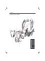
FOREWORD
This service manual has been specially prepared to provide all the
necessary information for the proper maintenance and repair of the
SD-50.
The SD-50 is a new type of motorcycle that has many technical
features such as :
V-belt drive automatic transmission
Forced air-cooling system
P.E Ignition system
Electric starter system
The SD-50 fits the needs of a wide variety of motorcycle users.
Those who will be servicing this motorcycle should carefully review
this manual before performing any repair or services.
PERIODIC MAINTENANCE AND
TUNE-UP PROCEDURE
2
ENGINE
3
FUEL AND LUBRICATION
SYSTEM
5
CHASSIS
6
SERVICING INFORMATION
C
O
PY
RI
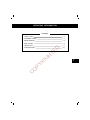
The SD-50 motorcycles distributed in your county might differ in
minor respects from the standard specification and, if they do, it
is because some minor modifications (which are of no consequence in most cases as far as servicing is concerned) has to be
made to comply with the starutory requirements of your country.
HYOSUNG MOTORS & MACHINERY INC.
Overseas Service
� COPYRIGHT HYOSUNG MOTORS & MACHINERY INC.
4
ELECTRICAL SYSTEM
G
Information of this manual is up-to-date at the time of issue.
Major modification and changes incorporated later will be advised
to HYOSUNG product distributor in each market. Therefore, if
newest information is requested in the future, please contact the
local HYOSUNG distributor.
1
H
TE
D
※
※
※
※
GENERAL INFORMATION
7
GENERAL INFORMATION
1
CONTENTS
1-1
FUEL AND OIL RECOMMENDATIONS
1-1
BREAKING-IN PROCEDURE
1-1
PRECAUTIONS AND GENERAL INSTRUCTIONS
1-2
SPECIAL MATERIALS
1-3
SPECIFICATIONS
1-4
C
O
PY
RI
G
H
TE
D
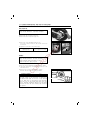
MODEL IDENTIFICATION
1-1 GENERAL INFORMATION
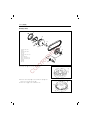
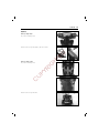
MODEL IDENTIFICATION
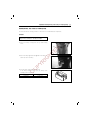
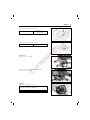
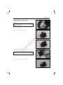
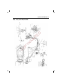
FRAME NUMBER
The frame number ① or VIN is stamped on the right side of the under
center in the frame.
①
ENGINE NUMBER
The engine serial number ② is stamped on the crankcase.
FUEL AND OIL RECOMMENDATIONS
②
RI
G
Be sure to the specified fuel and oils.
The following are the specification.
H
TE
D
These numbers are required especially for registering the motorcycle and
ordering spare parts.
FUEL
PY
Gasoline used should be graded 85-95 octane or higher.
An unleaded gasoline is recommended.
ENGINE OIL
C
FINAL GEAR OIL
O
For the HYOSUNG CCI system, use of“APOLLOIL BIKE-K”or“HYPOL HS”is highly recommended, but if they are not available, a good
quality two-stoke oil (non-diuent type) should be used.
Use a good quality SAE 10W/40 multi-grade motor oil.
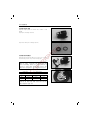
BREAKING-IN PROCEDURE
During manufacture only the best possible materials are used and all machined parts are finished to a very high standard but it is still
necessary to allow the moving parts to“BREAK-IN”before subjecting the engine to maximum stresses. The future performance and reliability of the engine depends on the care and restraint exercised during its early life. The general rules are as follow :
● Keep to these breaking-in speed limit:
Up to 1000 km(600 miles): Less than 4/5 throttle
● Upon reaching an odometer reading of 1000km(600 miles) you can subject the motorcycle to full throttle operation.
● Do not maintain constant engine speed for an extended time period during any portion of the break-in.
Try to vary the throttle position.
GENERAL INFORMATION 1-2
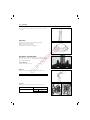
PRECAUTIONS AND GENERAL INSTRUCTIONS
Observe the following items without fail when disassembling and reassembling motorcycles.
□ Do not run engine indoors with little or no ventilation.
□ Be sure to replace packing, gaskets, circlips, O-rings and cotter pins with new ones.
CAUTION:
Never reuse a circlip after it has been removed from a shaft, it should be discarded and a new circlip must be
installed.
When installing a new circlip, care must be taken not to expend the end gap larger than required to slip the
circlip over the shaft.
After installing a circlip, always insure that it is completely seated in its groove and securely fitted.
G
H
TE
D
□ When tightening cylinder head or a case, torque the bolt or nut of larger thread diameter first and then
proceed to that of smaller diameter. They should also be tightened crosswise from inside to outside to
the specified torque.
□ Use special tools where specified.
□ Use genuine parts and recommended oils.
□ When two or more persons work together, pay attention to safety of each other.
□ After the reassembly, check parts for tightness and operation.
□ Treat gasoline, which is extremely flammable and highly exposive, with greatest care. Never use gasoline as cleaning solvent.
RI
Warning, Caution and Note are included in this manual occasionally, describing the following contents.
................ The parsonal safety of the rider may be involved. Disregarding this information
could result in injury to rider.
CAUTION ................. These instructions point out special service procedures or precautions that must
be followed to avoid damaging the machine.
NOTE ..................... This provides special information to make maintenance easier or important instructions clearer.
C
O
PY
WARNING
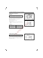
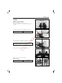
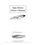
REPLACEMENT PARTS
When you replace any parts, use only genuine HYOSUNG replacement parts, or their equivalent. Genuine HYOSUNG parts are high
quality parts which are designed and built specifically for HYOSUNG
vehicles.
CAUTION:
Use of replacement parts which are not equivalent in quality to genuine HYOSUNG parts can lead to performance
problems and damage.
GENUINE
HYOSUNG
PARTS
1-3 GENERAL INFORMATION
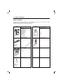
SPECIAL MATERIALS
The materials shown are required for maintenance works on the Model SD-50 and should be kept on hand for ready use. in addition,
such standard materials as cleaning fluids, lubricants, etc., should also available.
Methods of use are discussed in the text of this manual on later pages.
use
I ndustrial e
purpos
M ulti-
●
●
●
●
●
●
●
●
●
●
●
●
●
ase
G re
GREASE“G2”
99000-07C00
Oil seal
Throttle grip
Speedometer cable
Oil pump drive/driven gear
Kick starter gear
Kick starter shaft
Movable driven face
Fixed driven face
Starter pinion
Starter motor
Wheel bearing
Brake camshaft
Steering stem bearing
● Crankcase mating surface
● Final gear cover
THREAD LOCK
“1342”
99000-32050
● Front fork socket bolt
RI
15
1 2
PY
C
O
● Front brake caliper
SILICONE
GREASE
99000-25110
● Magneto rotor nut
THREAD LOCK
SUPER“1322”
99000-32110
● Reed valve securing screw
● Crankshaft oil seal outer
surface
G
e.
t yp ta
y.
S ag esis
G ra e & ine r
on
ket
ol
G as S ilic g as
&
uid
ss
L iq ventle h eat
ol
nt
S
elle
E xc
THREE BOND
No. 1215
99000-31110
use
Material
H
TE
D
Material
Anaerobic Adhesive
Sealant
1324
A4A021
THREAD LOCK
“1324”
99000-32030
GENERAL INFORMATION 1-4
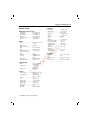
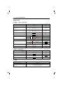
SPECIFICATIONS
ELECTRICAL
Ignition type …………………
Ignition timing ………………
…………………………………
Spark plug …………………
Battery ………………………
Generator ……………………
Fuse …………………………
Headlight ……………………
Front turn signal light ………
Rear turn signal light ………
Tail/Brake light ……………
Speedometer light …………
Oil level
indicator light ………………
Turn signal
indicator light ………………
Trunk light …………………
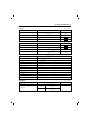
DIMENSIONS AND DRY MASS
Overall length ………………
Overall width ………………
Overall height ………………
Wheelbase …………………
Ground clearance ……………
Dry mass ……………………
1,780 mm(70.1 in)
660 mm(26.0 in)
1,065 mm(41.9 in)
1,221 mm(48.1 in)
112 mm (4.4 in)
84 kg(185 lbs)
Two-stroke, forced aircooled
Reed valve
1
41.0 mm(1.614 in)
37.4 mm(1.472 in)
49 ㎤(3.0 cu.in)
TRANSMISSION
……………………… Dry shoe, automatic,
centrifugal type
Reduction ratio …………… 2.815-0.866
………………………………… (Variable)
Drive system ……………… V-belt drive
O
C
CHASSIS
PY
Clutch
Front suspension …………… Telescopic, coil spring,
oil dampened
Rear suspension …………… Swingarm type, coil
spring, oil damped
Caster ……………………… 25°
Trail ………………………… 70 mm(2.75 in)
Steering angle ……………… 45°(right & left)
Turning radius ……………… 1.9 mm(6.2 ft)
Front tire size ……………… 100/80-10 53J
Rear tire size ……………… 100/80-10 53J
Front brake ………………… Disc
Rear brake ………………… Internal expanding
* The specifications are subject to change without notice.
12V 1.7 W
12V 1.7W
12V 2 W
CAPACITIES
RI
7.4:1
SIDEDRAFT V.V.
Polyurethane foam
element
Starter system ……………… Electric and kick
Lubrication system ………… HYOSUNG“CCI”
Fuel tank ……………………
…………………………………
Engine oil tank ……………
…………………………………
Final gear oil ………………
…………………………………
G
Type …………………………
…………………………………
Intake system ………………
Number of cylinder …………
Bore …………………………
Stroke ………………………
Piston displacement ………
Corrected compression
ratio …………………………
Carburetor ……………………
Air cleaner …………………
H
TE
D
ENGINE
HYOSUNG“CDI”
23°B.T.D.C.at
4,000 r/min
GOLDEN: BP6HS
12V 3Ah/10HR
Magneto
10 A
12V 15/15 W×2
12V 21 W
12V 10 W
12V 5/21 W
12V 3.4 W×2
4.8 L(1.3/1.1 US/lmp
gal)
1.2 L(1.2/1.0 US/lmp
qt)
80 ml(2.7/2.8 US/lmp
oz)
PERIODIC MAINTENANCE AND
TUNE-UP PROCEDURES
CONTENTS
PERIODIC MAINTENANCE SCHEDULE
2- 1
MAINTENANCE AND TUNE-UP PROCEDURE
2- 2
2- 2
CYLINDER HEAD NUTS AND EXHAUST PIPE BOLTS
2- 3
CYLINDER HEAD AND CYLINDER
2- 3
SPARK PLUG
2- 4
H
TE
D
BATTERY
FUEL LINE
AIR CLEANER
THROTTLE CABLE
G
ENGINE IDLE SPEED
BRAKES
TIRES
2- 5
2- 5
2- 5
2- 6
2- 7
2- 7
2-10
O
2-10
FRONT SUSPENSION
2-11
C
STEERING
PY
FINAL GEAR OIL
RI
OIL PUMP
2- 4
REAR SUSPENSION
2-11
CHASSIS BOLTS AND NUTS
2-11
GENERAL LUBRICATIONS
2-13
2
2-1 PERIODIC MAINTENANCE AND TUNE-UP PROCEDURES
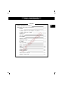
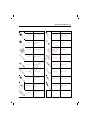
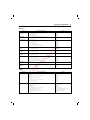
PERIODIC MAINTENANCE SCHEDULE
The chart below lists the recommended intervals for all the required periodic service work necessary to keep the motorcycle
operating at peak performance and economy. Mileages are expressed in terms of miles, kilometers and months.
NOTE:
More frequent servicing may be performed on motorcycles that are used under severe conditions.
PERIODIC MAINTENANCE CHART
Battery
Cylinder head nuts and exhaust pipe nuts
Cylinder head and cylinder
Spark plug
Every 2400
Every 4800
km
Initial 1000
Every 4000
Every 8000
months
2
6
12
I
I
-
T
T
-
-
-
C
-
C
R
l
l
-
RI
Air cleaner
Throttle cable play
PY
Engine idle rpm
Oil pump
O
Final gear oil
C
Brakes
Brake hose
Initial 600
G
Fuel line
miles
H
TE
D
INTERVAL: This intervals judged by odometer reading or month whichever comes first
Brake fluid
Replace every 4 years
-
C
-
I
I
-
I
I
-
I
I
-
I
-
I
I
I
-
I
I
-
Replace every 4 years
I
I
-
Replace every 2 years
Tire
I
I
-
Steering
I
I
-
Front suspension
I
-
I
Rear suspension
I
-
I
Chassis bolts and nuts
T
T
-
NOTE: I = Inspect and clean, adjust, lubricate or replace, if necessary.
A = Adjust, C = Clean, R = Replace, T = Tighten
PERIODIC MAINTENANCE AND TUNE-UP PROCEDURES 2-2
MAINTENANCE AND TUNE-UP PROCEDURE
This section describes the servicing procedures for each item of the Periodic Maintenance requirements.
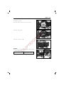
BATTERY
Inspect at Initially 1000km (600miles, 2momths), and
Every 4000km (2400miles, 6months) thereafter
● Remove the battery cover ① from the leg shield mounting
screws.
H
TE
D
①
O
PY
RI
G
● Remove the battery � lead and then � lead at the battery terminals and remove the battery.
C
● Check the battery voltage with the pocket tester.
If the voltage reading is below 12.0V, this battery needs
recharging. (Refer to page 5-10)
Battery voltage
09900-25002
Minimum 12.0V
Pocket tester
2-3 PERIODIC MAINTENANCE AND TUNE-UP PROCEDURES
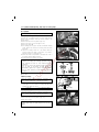
CYLINER HEAD NUT AND EXHAUST
PIPE BOLTS
Tighten at Initially 1000km (600miles, 2months), and
Every 4000km (2400miles, 6months) thereafter
H
TE
D
Cylinder head nuts, when they are not tightened to the specified
torque, may result in leakage of the compressed mixture and reduce
output. Tighten the cylinder head nuts in the following procedure.
● Remove the frame side cover.(Refer to page 6-3)
● Remove the spark plug cap.
● Remove the cylinder head cover bolts.
(Refer to page 3-5)
● Tighten the nuts evenly one by one in stages until each one is
tightened to the specified torque. Tighten the nuts in the order
indicated.
Tightening torque
8-12 N∙m
(0.8-1.2 kg-m, 6.0-8.5 lb-ft)
Exhaust pipe nut
8-12 N∙m
(0.8-1.2 kg-m, 6.0-8.5 lb-ft)
O
PY
RI
G
Cylinder head nut
C
CYLINER HEAD AND CYLINDER
Remove carbon Every 8000km (4800miles, 12months)
Carbon deposits in the combustion chamber and the cylinder head
will raise the compression ratio and may cause preignition or overheating. Carbon deposited at the exhaust port of the cylinder will
prevent the flow of exhaust gases, reducing the output. Remove
carbon deposits periodically.
Carbon
PERIODIC MAINTENANCE AND TUNE-UP PROCEDURES 2-4
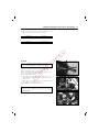
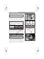
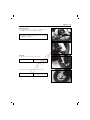
SPARK PLUG
Clean Every 4000km (2400miles, 6months) and
Replace Every 8000km (4800miles, 12months)
09900-20804
Spark plug gap
H
TE
D
Neglecting the spark pulg maintenance eventually leads to difficult starting
and poor performance. If the spark plug is used for a long period, the electrode gradually burns away and carbon builds up along the inside part. In
accordance with the Periodic Inspection Chart, the plug should be removed
for inspection, cleaning and to reset the gap.
● Carbon deposits on the spark plug will prevent good sparking and cause
misfiring. Clean the deposits off periodically.
● If the center electrode is fairly worn down, the plug should be replaced
and the plug gap set to the specified gap using a thickness gauge.
Thickness gauge
0.6-0.7 mm(0.024-0.028 in)
● Check the spark plug for burnt condition. If abnormal, replace
the plug as indicated in the chart.
REMARKS
BP5HS
If the standard plug is apt to get wet,
replace with this plug.
BP6HS
Standard
BP7HS
If the standard plug is apt to get overheat,
replace with this plug.
PY
RI
G
GOLDEN
O
● Tighten the spark plug to the specification.
C
Spark plug
Tightening torque
25-30 N∙m
(2.5-3.0 kg-m, 18.0-21.0 lb-ft)
NOTE:
● To check the spark plug, first make sure that the fuel used is unleaded gasoline, and if plug is either sooty with carbon or burnt white,
replace it.
● Confirm the thread size and reach when replacing the plug.
FUEL LINE
Inspect at Initially 1000km (600miles, 2momths), and
Every 4000km (2400miles, 6months) thereafter
Replace Every 4 years.
0.6~0.7 mm
(0.024~0.028in)
2-5 PERIODIC MAINTENANCE AND TUNE-UP PROCEDURES
AIR CLEANER
Clean Every 4000km (2400miles, 6months)
If the air cleaner is clogged with dust, intake resistance will be
increased with a resultant decrease in power output and an
increase in fuel consumption. Check and clean the element in the
following manner.
● Remove the frame side cover.(Refer to page 6-3)
● Remove the cleaner cover by removing the screw.
● Remove the element ①.
● Fill a washing pan of a proper size with non-flammable cleaning
solvent. Immerse the element in the cleaning solvent and wash
them clean.
● Squeeze the cleaning solvent out of the washed element by
pressing it between the palms of both hands: do not twist or
wiring the element or if will develop tears.
● Immerse the element in SAE 10/W40 oil, and squeeze the oil out of
the element leaving it slightly wet with oil.
● Fit the elements to the cleaner case properly.
H
TE
D
①
�
RI
G
CAUTION:
● Before and during the cleaning operation, inspect
the element for tears. A torn element must be
replaced.
● Be sure to position the element snugly and correctly, so that no incoming air will bypass it.
Remember, rapid wear of piston rings and cylinder
bore is often caused by a defective or poorly fitted
element.
PY
C
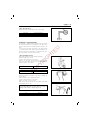
THROTTLE CABLE
O
� Non-flammable cleaning solvent
� SAE 10W40
�
Adjust at Initially 1000km (600miles, 2momths), and
Every 4000km (2400miles, 6months) thereafter
● Loosen the lock nut ① and adjust the cable play � by turning
adjuster ② in or out to obtain the following cable play. After
adjusting play, tighten the lock nut.
Cable play
0.5-1.0 mm(0.020-0.040 in)
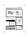
ENGINE IDLE SPEED
Adjust at Initially 1000km (600miles, 2momths), and
Every 4000km (2400miles, 6months) thereafter
● Adjust the throttle cable play.
● Remove the frame side cover.(Refer to page 6-3)
● Warm up the engine.
NOTE:
A warm engine means an engine that has been run for 10
minutes.
→ ←�
②
①
PERIODIC MAINTENANCE AND TUNE-UP PROCEDURES 2-6
● Connect an electric tachometer to the connecting portion of the
high tension lead. Use the selector key“C”position.
09900-26006
Tachometer
● Asjust the throttle stop screw to obtain the idle r/min as follows.
Idle r/min
1800±50 r/min
H
TE
D
● Finally adjust the throttle cable play.
G
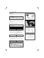
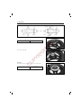
OIL PUMP
RI
Inspect at Initially 1000km (600miles, 2momths), and
Every 4000km (2400miles, 6months) thereafter
C
O
PY
The engine oil is fed by the oil pump to the engine. The amount of
oil fed to it is regulated by engine speed and oil pump control lever
which is controlled by amount of throttle opening.
Check the oil pump in the following manner to confirm correct operation for throttle valve full opening position.
● Turn the throttle grip full open.
● Check whether the mark ① on the oil pump control lever is
aligned with the index mark ② when the throttle valve is positioned as above.
● If the marks are not aligned, loosen lock nuts ③ and turn the
adjuster ④ in or out to align the marks.
● After aligning the marks, tighten the lock nuts.
②
①
CAUTION:
Oil pump cable adjustment must be done after throttle
cable adjustment.
③
④
2-7 PERIODIC MAINTENANCE AND TUNE-UP PROCEDURES
FINAL GEAR OIL
Inspect at Initially 1000km (600miles, 2momths), and
Every 8000km (4800miles, 12months) thereafter
Inspect final gear oil periodically following procedure below.
● Remove the side cover.(Refer to page 6-3)
● Remove the clutch cover.(Refer to page 3-5)
①
H
TE
D
● Remove the oil level bolt ① and inspect oil level.
If the level is below the level hole, add oil until oil flows from
the level hole.
● Tighten the oil level bolt to the specified torque.
9-15 N∙m
(0.9-1.5 kg-m, 6.5-11.0 lb-ft)
Tightening torque
BRAKES
RI
G
Inspect at Initially 1000km (600miles, 2momths), and
Every 4000km (2400miles, 6months) thereafter
Replace(change) brake fluid Every 2 years
Replace brake hose Every 4 years
PY
FRONT BRAKE FLUID LEVEL
C
O
● Keep the motorcycle upright and place the handlebar straight.
● Check brake fluid level by observing the lower limit line on the
brake fluid reservoir.
● When the level is bolow the lower limit line, replenish
with brake fluid that meets the following specification.
Specification and classification
DOT4
WARNING:
The brake system of this motorcycle is filled with a
glycolbased brake fluid. Do not use or mix different
type of fluid such as silicone-based and petroleumbased. Do not use any brake fluid taken from old,
used or unsealed containners. Never re-use the brake
fluid left over from the last servicing and stored for
long periods.
Lower limit line
Oil drain plug
PERIODIC MAINTENANCE AND TUNE-UP PROCEDURES 2-8
WARNING:
Brake fluid, if it leaks, will interfere with safe running and
immediatery discolor painted surfaces.
Check the brake hoses for cracks and hose joints for leakage before riding.
BRAKE PADS
H
TE
D
Wearing condition of brake pads can be checked by observing the
limit line ① marked on the pad. When the wear exceeds the limit
mark, replace the pads with new ones.(Refer to page 6-13.)
BLEEDING AIR FROM THE BRAKE FLUID CIRCUIT
C
O
PY
RI
G
Air trapped in the fluid circuit acts like a cushion to absorb a large
proportion of the pressure developed by the master cylinder and
thus interferes with the full braking performance of the brake
caliper. The presence of air is indicated by “sponginess” of the
brake lever and also by lack of braking force. Considering the danger to which such trapped air exposes the machine and rider, it is
essectial that, after remounting the brake and restoring the brake
system to the normal condition, the brake fluid circuit be purged of
air in the following manner:
● Fill up the master cylinder reservoir to the upper end of the
inspection window. Replace the reservoir cap to prevent entry of
dirt.
● Attach a pipe to the caliper bleeder valve, and insert the free
end of the pipe into a receptacle.
● Bleed air from the bleeder valve.
● Squeeze and release the brake lever several times in rapid succession, and squeeze the lever fully without releasing it. Loosen
the bleeder valve by turning it a quarter of a turn so that the
brake fluid runs into the receptacle: this will remove the tension
of the brake lever causing it to touch the handlebar grip. Then,
close the valve, pump and squeeze the lever, and open the
valve. Repeat this process until the fluid flowing into the receptacle no longer contains air bubbles.
①
2-9 PERIODIC MAINTENANCE AND TUNE-UP PROCEDURES
NOTE:
Replenish the brake fluid reservoir as necessary while
bleeding the brake system.
Make sure that there is always some fluid visible in the
reservoir.
● Close the bleeder valve, and disconnect the pipe. Fill the reservoir to the upper end of the inspection window.
Bleeder valve
6-9 N∙m
(0.6-0.9 kg-m, 4.5-6.5 lb-ft)
H
TE
D
Tightening torque
CAUTION:
Handle the brake fluid with care: the fluid reacts
chemically with paint, plastics, rubber materials, etc.
REAR BRAKE
G
Adjust by turning the adjusting nut ① so that the play � is 15-25
mm (0.6-1.0 in) as shown in the illustration.
PY
15-25mm
RI
�
O
Brake lining wear limit
①
Index mark
C
This motorcycle is equipped with the brake lining wear limit indicator
on the rear brake. As shown in the illustration at right, at the condition of normal lining wear, an extended line from the index mark
on the brake camshaft should be within the range embossed on the
crankcase. To check wear of the brake lining, follow the steps
below.
● First check if the brake system is properly adjusted.
● While operating the brake, check to see that the extension line
from the index mark is within the range on the crankcase.
● If the index mark is outside the range as shown in the illustration at right, the brake shoe assembly should be replaced to
ensure safe operation.
Brake lining
wear limit
The extension line of the index mark is within the range.
Index mark
Brake lining
wear limit
The extension line of the index mark is outside of the range.
PERIODIC MAINTENANCE AND TUNE-UP PROCEDURES 2-10
TIRES
Inspect at Initially 1000km (600miles, 2momths), and
Every 4000km (2400miles, 6months) thereafter
TIRE PRESSURE
If the tire pressure is too high, the motorcycle will tend to ride
stiffly and have poor traction. Conversely, if the tire pressure is too
low, stability will be adversely affected. Therefore, maintain the correct tire pressure for good roadability and to prolong tire life.
SOLO RIDING
H
TE
D
CAUTION:
The standard tire fitted on this motorcycle is
100/90-10 56J for front and rear. The use of a
tire other than the standard may cause handling
instability. It is highly recommended to use a
HYOSUNG Genuine Tire.
OVER
DUAL RIDING
kPa
kg/㎠
psi
kPa
kg/㎠
FRONT
125
1.25
18
-
-
REAR
200
2.00
29
-
-
-
-
RI
TIRE TREAD CONDITION
psi
G
COLD INFLATION
TIRE PRESSURE
STEERING
O
1.6 mm (0.064 in)
Tire depth gauge
C
Front and Rear
09900-20805
PY
Operating the motorcycle with the excessively worn tires will
decrease riding stability and consequently invite a dangerous situation. It is highly recommended to replace the tire when the remaining depth of tire tread reaches the following specification.
Inspect at Initially 1000km (600miles, 2momths), and
Every 4000km (2400miles, 6months) thereafter
Steering should be adjusted properly for smooth turning of handlebars and safe running. Too stiff steering prevents smooth turning of
handlebars and too loose steering will cause poor stability.
Check that there is no play in the front fork assembly by supporting
the machine so that the front wheel is off the ground, with wheel
straight ahead, grasp lower shock absorber near the axle and pull
forward. If play is found, perform steering bearing adjustment.(Refer
to page 6-24)
NORMAL
SHORT
2-11 PERIODIC MAINTENANCE AND TUNE-UP PROCEDURES
FRONT SUSPENSION
Inspect at Initially 1000km (600miles, 2momths), and
Every 8000km (4800miles, 12months) thereafter
Inspect the front shock absorber for oil leakage or other damage,
and replace the defective parts, if necessary.
REAR SUSPENSION
Inspect at Initially 1000km (600miles, 2momths), and
Every 8000km (4800miles, 12months) thereafter
H
TE
D
Inspect the rear shock absorber for oil leak and the mounting rubbers including engine mountings for wear and damage. Replace the
defective part if necessary.
CHASSIS BOLTS AND NUTS
G
Tighten at Initially 1000km (600miles, 2momths), and Every 4000km (2400miles, 6months) thereafter
ITEM
N∙m
kg∙m
lb∙ft
33-52
3.3-5.2
24.0-37.5
Front axle nut
②
Steering stem lock nut
60-100
6.0-10.0
43.5-72.5
③
Handlebar clamp nut
48-52
4.8-5.2
34.5-37.5
④
Handlebar set bolt
22-28
2.2-2.8
16.0-20.0
⑤
Front brake master cylinder bolt
8-12
0.8-1.2
6.0-8.5
⑥
Front brake hose union bolt
20-25
2.0-2.5
14.5-18.0
⑦
Front brake caliper mounting bolt
18-28
1.8-2.8
13.0-20.0
⑧
Front brake air bleeder valve
6-9
0.6-0.9
4.5-6.5
⑨
Rear axle nut
60-90
6.0-9.0
43.5-65.0
⑩
Rear shock absorber bolt (upper and lower)
22-35
2.2-3.5
16.0-25.5
⑪
Rear brake cam lever nut
6-9
0.6-0.9
4.5-6.5
⑫
Engine mounting bracket nut
48-72
4.0-6.0
34.5-52.0
⑬
Engine mounting nut
40-60
7.0-10.0
29.0-43.5
O
PY
①
C
No.
RI
These bolts and nuts listed below are important safety parts. They must be loosened first and retightened, to the specified
torque with a torque wrench.
PERIODIC MAINTENANCE AND TUNE-UP PROCEDURES 2-12
⑨
①
H
TE
D
⑩
⑪
G
②
RI
③
C
O
PY
④
⑥
⑤
⑬
⑧
⑦
⑫
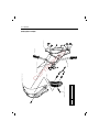
2-13 PERIODIC MAINTENANCE AND TUNE-UP PROCEDURES
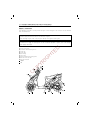
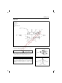
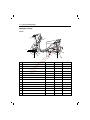
GENERAL LUBRICATIONS
Proper lubrication is important for smooth operation and long life of each working part of the motorcycle. The major lubrication
points are indicated below.
NOTE:
* Lubricate expodes parts which are subject to rust with motor oil grease.
* Before lubricating each part, clean off any rusty spots and wipe off any grease, oil dirt of grime.
WARNING:
Be careful not to apply too much grease to the rear break camshaft. If grease gets on the linings,
G
Steering stem bearing
Speedometer cable and drive gear box
Throttle grip
Throttle cable
Wheel bearing
Center stand
Engine mounting bracket pivoting portion
Rear brake lever and cable
Rear brake camshaft
RI
①
②
③
④
⑤
⑥
⑦
⑧
⑨
H
TE
D
brake slippage will result.
G : Grease
PY
O : Oil
O
⑧G
④O
③G
C
②G
①G
⑨G
⑤G
②G
⑦G
⑥G
⑧G
ENGINE
CONTENTS
ENGINE REMOVAL AND REMOUNTING
3- 1
ENGINE REMOVAL
3- 1
ENGINE REMOUNTING
3- 3
ENGINE DISASSEMBLY
3- 4
ENGINE COMPONENTS INSPECTION AND SERVICING
3-13
3-13
OIL SEALS
3-13
H
TE
D
BEARINGS
CRANKSHAFT
3-13
AUTOMATIC CLUTCH INSPECTION
3-14
CYLINDER HEAD
3-16
CYLINDER
G
PISTON
ENGINE REASSEMBLY
PY
OIL SEALS
RI
REED VALVE
3-17
3-17
3-19
3-20
3-20
3-20
BUSHINGS
3-21
CRANKSHAFT
3-22
CRANKCASE
3-23
CENTER STAND
3-24
REAR AXLE SHAFT, BRAKE AND WHEEL
3-25
TRANSMISSION
3-27
STARTER DRIVEN GEAR AND STARTER MOTOR
3-29
MOVABLE DRIVEN AND CLUTCH
3-30
MOVABLE DRIVE
3-33
KICK STARTER
3-35
PISTON
3-36
OIL PUMP AND INTAKE PIPE
3-38
MAGNETO
3-39
MUFFLER
3-40
C
O
BEARINGS
3
3-1 ENGINE
ENGINE REMOVAL AND
REMOUNTING
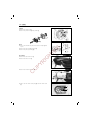
ENGINE REMOVAL
Before taking the engine out of the frame, thoroughly clean the
engine with a suitable cleaner. The procedure of engine removal is
sequentially explained as follows.
● Remove the frame side covers. (Refer to page 6-3)
● Remove the air cleaner by removing the mounting bolts and
clamp screw.
①
O
PY
RI
G
● Disconnect the ignition coil lead wires and spark plug cap.
H
TE
D
②
C
● Disconnect the oil pump cable ③ and the thermoelement lead
coupler ④.
● Disconnect the throttle cable. (Refer to page 4-2)
④
③
● Disconnect the carburetor hoses and oil hose.
Vacuum hose ⑤.
Fuel hose ⑥.
Oil hose ⑦.
⑤
⑥
⑦
ENGINE 3-2
● Disconnect the magneto lead wire and starter lead wire.
● Remove the rear brake cable ② by removing the bolt ①, bolt
③ and adjuster nut.
O
PY
RI
G
H
TE
D
①
C
● Remove the rear shock absorber mounting lower bolt.
● Remove the engine mounting shaft and remove the engine from
the frame.
②
③
3-3 ENGINE
ENGINE REMOUNTING
The engine can be mounted in the reverse order of removal.
● Install the damper to the crankcase bracket as shown in the
illustration.
● With“UP”mark faced upward, install the crankcase bracket ①
on the frame. Do not tighten the bracket bolt ② at this stage.
Pull up on the rear part of crankcase bracket and while holding
it, tighten the bracket bolt ② to specification. Tighten both the
rear shock absorber bolt ④ and engine mounting bolt ③ to
specification.
Front side
①
“UP”mark
10mm
8mm
Damper
N∙m
48-72
40-60
20-30
kg∙m
4.8-7.2
4.0-6.0
2.0-3.0
lb-ft
34.5-52.0
29.0-43.5
14.5-21.5
③
①
②
④
O
PY
RI
G
②
③
④
H
TE
D
Tightening torque
C
● Install the magneto lead wire and starter motor lead wire correctly.
After remounting the engine, route the wiring harness properly
(Refer to page 6)and following adjustments are necessary.
Page
∙Throttle cable play
2-5
∙Idling adjustment
2-5
∙Oil pump cable paly
2-6
∙Rear brake cable adjustment
2-9
∙Air bleeding at oil pump
4-8
⑤
ENGINE 3-4
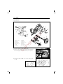
ENGINE DISASSEMBLY
MUFFLER
● Remove the muffler by removing the bolts and nuts.
MAGNETO
②
①
● Remove the cooling fan.
● Remove the magneto rotor nut ① with the special tool.
Rotor holder
● Remove the magneto rotor with the special tool.
09930-30163
Rotor removerr
Special tool
②
PY
RI
G
● Remove the magneto stator and key.
H
TE
D
09930-40113
O
REED VALVE
Special tool
C
● Remove the intake pipe ① with reed valve.
①
②
OIL PUMP
②
● Remove the oil pump ①.
● Remove the oil pump driven gear ②.
①
②
3-5 ENGINE
CYLINDER
● Remove the cylinder cowling.
● Remove the cylinder head ① and cylinder ②.
②
①
④
PISTON
● Place a cloth beneath the piston and remove the circlip ① with
a pliers.
● Remove the piston pin ② and piston ③.
● Remove the piston pin bearing ⑤.
H
TE
D
③
KICK STARTER
⑤
RI
G
● Remove the kick starter lever ①.
● Remove the clutch cover ②.
①
②
O
PY
①
③
C
● Remove the crankcase left cover ③.
②
● Remove the kick starter shaft spring ④ and kick starter shaft
⑤.
⑤
④
ENGINE 3-6
KICK STARTER DRIVEN GEAR
● Remove the E-ring ① with the long nose plier.
● Remove the spacer ②, spring ③ and kick starter driven gear
④.
④ ③
② ①
MOVABLE DRIVE FACE
09910-20115
Conrod holder
③
④
PY
RI
● Remove the fixed drive face ② and V-belt ③.
● Disassemble the movable drive face ④.
G
CAUTION:
This nut has left-hand thread.
H
TE
D
● Remove the kick starter driven nut with the special tool.
O
STARTER DRIVEN GEAR
②
C
● Remove the starter driven gear ①.
①
MOVABLE DRIVEN FACE
● Remove the clutch housing with the special tool.
09930-40113
Rotor holder
①
3-7 ENGINE
● Loosen the clutch shoe nut with the special tool.
09930-40113
Rotor holder
● Remove the nut while holding down the clutch shoe assembly by
both hands as shown in the illustration.
①
;;
;;
;;
;;
;;
;;
;;
;;;;
②
① Nut
② Clutch shoe assembly
③ Spring
H
TE
D
WARNING:
Gradually back off the clutch shoe assembly pressed
down by hand to counter the clutch spring load.
Releasing the hand suddenly may cause the parts to
fly apart.
②
①
④
G
③
PY
RI
CAUTION:
Do not attempt to diassemble the clutch shoe
assembly.
It is not serviceable.
O
● Using a thin blade screwdriver or the like, pry up the movable
driven face spring guide ④.
● Remove the pins ⑤, movable driven face ⑥ and fixed driven
face ⑦.
C
⑤
⑦
⑥
● Remove the roller bearing � with the special tools.
09923-73210
09930-30102
Bearing remover
Sliding shaft
CAUTION:
The removed bearing should be replaced with a new one.
Special tool
�
Special tool
ENGINE 3-8
● Remove the circlip �.
�
�
�
�
● Remove the bearing � with the special tool.
09941-50111
Wheel bearing remover
Special tool
H
TE
D
CAUTION:
The removed bearing should be replaced with a new
one.
TRANSMISSION
①
G
● Drain gear oil.
● Remove the gear box cover ①.
● Remove the driveshaft ②.
O
PY
RI
②
C
● Remove the oil seal ③ from the gear box cover with the special
tool.
09913-50121
Oil seal remover
Special tool
③
CAUTION:
The removed oil seal should be replaced with a new
one.
● Remove the bearing ④ with the special tool.
Installer
09943-88211
Bearing remover
(Bearing installer)
CAUTION:
The removed bearing should be replaced with a new
one.
④
3-9 ENGINE
● Remove the circlip ④ and final driven gear ⑤.
● Remove the idle shaft ⑥.
④
⑥
⑤
● Remove the drive shaft bearing ⑦.
Special ①
tool
Sliding shaft
09921-20210
Bearing remover
⑦
H
TE
D
09930-30102
WHEEL, BRAKE
③
①
②
O
PY
RI
● Remove the rear axle nut ① and washer ②.
● Remove the rear wheel ③.
G
Special ②
tool
C
● Remove the brake shoes ⑤ and rear axle shaft ④.
⑤
④
⑤
● Remove the bearing retainer ⑥.
⑦
⑥
ENGINE 3-10
● Remove the bearing ⑦ with the special tool.
⑦
Bearing remover
(Bearing installer)
09913-75820
Special tool
● Remove the oil seal ⑧ with the special tool.
09913-50121
Oil seal remover
H
TE
D
⑧
Special tool
CENTER STAND
PY
RI
G
● Remove the return spring ①.
O
①
C
● Remove the cotter pin ②, washer ③ and shaft ④.
● Remove the center stand ⑤.
⑤
③②
④
CRANKCASE
● Remove the crankcase securing screws.
NOTE:
Loosen the crankcase nuts diagonally.
09920-13120
Crankcase separation tool
3-11 ENGINE
● Remove the crankshaft with the special tool.
C
O
PY
RI
G
● Remove the bearings, oil seals and bushing.
H
TE
D
Crankshaft remover
(Crankcase separating tool)
09920-13120
ENGINE 3-12
● Using two steel tubes of appropriate size, press out the engine
mounting bushings on a vise as shown in the illustration.
Bushing
Front side
28.1
25.5
H
TE
D
Bushing
C
O
PY
RI
G
Crankcase
15
Rear side
Bushing
Crankcase
15
20
22.3
3-13 ENGINE
ENGINE COMPONENTS INSPECTION AND SERVICING
BEARINGS
Wash the bearing with cleaning solvent and lubricate with motor oil
before inspecting.
Turn the inner ring and check to see that the inner ring turns
smoothly. If it does not turn lightly, quietly and smoothly, or if noise
is heard, the bearing is defective and must be replaced with a new
one.
OIL SEAL
G
H
TE
D
Damage to the lip of the oil seal may result in leakage of the fuelair mixture or oil. Inspect for damage and be sure to replace the
damaged seal if found.
CRANKSHAFT
RI
CRANKSHAFT RUNOUT
PY
Support crankshaft by “V” blocks, with the dial gauge rigged to
read the runout as shown.
C
09900-21304
O
Service limit
0.05 mm(0.002 in)
Excessive crankshaft runout is often responsible for abnormal engine
vibration. Such vibration shortens engine life.
V-block(100 mm)
09900-20701
Magnetic stand
09900-20206
Dial gauge(1/100 mm)
CONDITION OF BIG END BEARING
Turn the crankshaft with the conrod to feel the smoothness of
rotary motion in the big end. Move the rod up and down while
holding the crankshaft rigidly to be sure that there is no rattle in
the big end.
Wear on the big end of the conrod can be estimated by checking
the movement of the small end of the rod. This method can also
check the extent of wear on the parts of the conrod's big end.
If wear exceeds the limit, conrod, crank pin and crank pin bearing
should all be replaced.
Service limit
3.0 mm(0.12 in)
ENGINE 3-14
CONROD SMALL END BORE I.D.
Measure the conrod small end diameter with a caliper gauge.
Service limit
14.047 mm(0.5530 in)
09900-20605
Dial calipers
AUTOMATIC CLUTCH INSPECTION
H
TE
D
This motorcycle is equipped with an automatic clutch and variable
ratio belt drive transmission. The engagement of the clutch is governed by engine RPMs and centrifugal mechanism located in the
clutch.
To insure proper performance and longevity of the clutch assembly
it is essential that the clutch engages smoothly and gradually. Two
inspection checks must be performed to thoroughly check the operation of the drivetrain. Follow the procedures listed.
1. INITIAL ENGAGEMENT INSPECTION
PY
RI
G
Warm up the motorcycle to normal operating temperature.
Remove the right frame side cover.
Connect an electric tachometer to the engine.
Seated on the motorcycle with the motorcycle on level ground,
increase the engine RPMs slowly and note the RPM at which the
motorcycle begins to move forward.
ENGAGEMENT R/MIN
C
STD
Tolerance
Tachometer
O
09900-26006
3300 r/min
± 300 r/min
2. CLUTCH“LOCK-UP”INSPECTION
Perform this inspection to determine if the clutch is engaging fully
and not slipping.
Warm the engine to normal operating temperatures.
Connect an electric tachometer to the engine.
Apply the rear brake as firm as possible.
Briefly open the throttle fully and note the maximum engine RPMs
sustained during the test cycle.
CAUTION:
Do not apply full power for more than 10 seconds or
damage to the clutch or engine may occur.
LOCK-UP R/MIN
STD
Tolerance
5800 r/min
± 500 r/min
3-15 ENGINE
If the engine r/min does not coincide with the specified r/min range,
then disassemble the clutch.
Clutch shoe - inspect the shoes visually for chips, cracking, uneven
wear and burning, and check the thickness of the shoes with
vernier calipers. If the thickness is less than the following service
limit, replace them as a set.
Clutch springs - visually inspect the clutch springs for stretched coils
or broken coils.
Service limit
2.0 mm(0.08 in)
H
TE
D
CAUTION:
Clutch shoes or springs must be changed as a set
and never individually.
Clutch wheel - inspect visually the condition of the inner clutch
wheel surface for scrolling, cracks, or uneven wear. Measure inside
diameter of the clutch wheel with inside calipers. Measure the
diameter at several points to check for an out-of-round condition as
well as wear.
110.35 mm(4.344 in)
PY
RI
G
Service limit
O
DRIVE BELT
C
Remove the drive belt and check for cracks, wear and separation.
Measure the drive belt width with a vernier calipers. Replace it if
the belt width is less than the service limit or any defect has been
found.
Service limit
15.3 mm(0.602 in)
CAUTION:
Always keep the drive belt away from any greasy
mater.
DRIVE FACE
Inspect the belt contact surface of the drive faces for wear, scratches or any abnormality. If there is something unusual, replace the
drive face with a new one.
Measuring clutch wheel I.D.
ENGINE 3-16
ROLLER AND SLIDING SURFACE
Inspect each roller and sliding surface for wear or damage.
DRIVEN FACE SPRING
Service limit
104.5 mm(4.11 in)
DRIVEN FACE PIN AND OIL SEAL
H
TE
D
Measure the free length of the driven face spring. If the length is
shorter than the service limit, replace the spring with a new one.
O
PY
RI
G
Turn the driven faces and check to see that the driven faces turn
smoothly.
If any stickness or hitches are found, visually inspect the lip of oil
seal, driven face sliding surface and sliding pins for wear or damage.
DRIVEN FACE
C
Inspect the belt contacting surface of both driven faces for any
scratches, wear and damage.
Replace driven face with new one if there are any abnormality.
CYLINDER HEAD
Decarbon the combustion chamber.
Check the gasketed surface of the cylinder head for distortion with
a straightedge and thickness gauge, taking a clearance reading at
several places.
09900-20803
Service limit
Thickness gauge
0.1 mm(0.004 in)
3-17 ENGINE
If the largest reading at any portion of the straightedge exceeds the
limit, rework the surface by rubbing it against emery paper (of
about # 400) laid flat on the surface plate in a lapping manner.
The gasketed surface must be smooth and perfectly flat in order to
secure a tight joint: a leaky joint can be the cause of reduced
power output and increased fuel consumption.
CYLINDER
Decarbon exhaust port and upper part of the cylinder, taking care
not to damage the cylinder wall surface.
Cylinder gauge set
G
09900-20508
H
TE
D
The wear of the cylinder wall is determined from diameter reading
taken at 20 mm from the top of the cylinder with a cylinder gauge.
If the wear thus determined exceeds the limit indicated below,
rework the bore to the next oversize by using a boring machine or
replace the cylinder with a new one. Oversize piston is available in
one size: 0.5 mm oversize.
41.070 mm(1.6169 in)
RI
Service limit
O
PY
After reworking the bore to an oversize, be sure to chamfer the
edges of ports and smooth the chamfered edges with emery paper.
To chamfer, use a scraper, taking care not to nick the wall surface.
C
NOTE:
Minor surface flaws on the cylinder wall due to
seizure or similar abnormalities can be corrected by
grinding the flaws off with fien-grain emery paper. If
the flaws are deep grooves or otherwise persist, the
cylinder must be reworked with a boring machine to
the next oversize.
PISTON
CYLINDER TO PISTON CLEARANCE
Cylinder-to-piston clearance is the difference between piston diameter and cylinder bore diameter. Be sure to take the maked diameter
at right angles to the piston pin. The value of elevation � is prescribed to be 15 mm from the skirt end.
09900-20202
Service limit
Micrometer(25-50 mm)
40.885 mm(1.6096 in)
ENGINE 3-18
As a result of the above measurement, if the piston-to-cylinder
clearance exceeds the following limit, overhaul the cylinder and use
an oversize piston, or replace both cylinder and piston. The measurement for the bore diameter should be taken in the intake-toexhaust port direction and at 20mm from the cylinder top surface.
Unit: mm
STD
41.005-41.020
40.935-40.950
0.065-0.075
Cylinder
Piston
Cylinder to piston
Service Limit
41.070
40.885
0.120
DE-CARBONING
O
PY
RI
G
H
TE
D
De-carbon the piston and piston ring grooves, as illustrated. After
cleaning the grooves, fit the rings and rotate them in their respective grooves to be sure that they move smoothly.
Carbon in groove is liable to cause the piston ring to get stuck in
the groove, and this condition will lead to reduced engine power
output.
A piston whose sliding surface is badly grooved or scuffed due to
overheating must be replaced. Shallow grooves or minor scuff can
be removed by grinding with emery paper of about # 400.
PISTON PIN BORE
C
Using a caliper gauge, measure the piston pin bore inside diameter.
If reading exceeds the following service limit, replace it with a new
one.
09900-20605
Service limit
Dial calipers
10.036 mm(0.4079 in)
PISTON PIN O.D.
Using a micrometer, measure the piston outside diameter at three
positions.
09900-20205
Service limit
Micremeter(0-25 mm)
9.980 mm(0.3929 in)
3-19 ENGINE
PISTON RINGS
Check each ring for end gap, reading the gap with a thickness
gauge shown in the illustration. If the end gap is found to exceed
the limit, indicated below, replace it with a new one.
The end gap of each ring is to be measured with the ring fitted
squarely into the cylinder bore and held at the least worn part near
the cylinder bottom, as shown in the illustration.
09900-20803
Thickness gauge
Service limit
0.75 mm(0.030 in)
1st
2nd
3.7 mm(0.15 in)
3.5 mm(0.14 in)
G
Service Limit
H
TE
D
As the piston ring wears, its end gap increases reducing engine
power output because of the resultant blow by through the enlarged
gap. Here lies the importance of using piston rings with end gaps
within the limit.
Measure the piston ring free end gap to check the spring tension.
RI
Fix the piston ring in the piston ring groove, measure the ring side
clearance with the thickness gauge while matching the sliding surfaces of piston and ring.
0.020-0.060 mm
(0.0008-0.0024 in)
O
PY
STD clearance
REED VALVE
C
When reinstalling the reed valve and stopper plate to the body,
align the both cut on the reed valve and stopper plate.
Apply Thread Lock“1324”to the stopper plate securing screws.
99000-32030
Thread Lock“1324”
ENGINE 3-20
ENGINE REASSEMBLY
Reassembly is generally performed in the reverse order of disassembly, but there are a number of reassembling steps that demand
or deserve detailed explanation or emphasis. These steps will be
taken up for respective parts and components.
OIL SEALS
99000-07000
Grease“G2”
H
TE
D
Fit the oil seals to the crankcase following the procedure below.
Replace removed oil seals with new ones.
● Apply grease to the lip of the oil seals.
● Be sure to apply Thread Lock“1324”to outer surfaces of right
and left crankshaft oil seals to prevent them from moving.
Thread Lock“1324”
G
99000-32030
RI
● When fitting the oil seal in the crankcase, insert it slowly with
the special tools.
Oil seal installer
09924-74510
Oil seal installer handle
PY
09913-75830
09924-74540
Oil seal installer attachment
BEARINGS
C
O
NOTE:
Align the oil seal with edge � of the crankcase as
shown in the illustration.
Install new bearings with the special tool.
09913-75810
Bearing installer
09913-76010
Bearing installer
ell
S h
A valnia
I ndustrial e
purpos
M ulti-
3
ase
G re
3-21 ENGINE
BUSHINGS
②
Using two steel tubes of appropriate size and a vise, press the
mounting bushings ① and ② into the crankcase holes as shown in
the illustration.
NOTE:
Knurled end ③ should face inside. Protruside � and �
should be in the same dimension.
C
O
PY
RI
G
H
TE
D
①
ENGINE 3-22
CRANKSHAFT
①Crankshaft
②Crankcase(R)
③Oil seal
④Oil seal
⑤Oil pump drive gear
⑥Oil pump drive gear
⑦Oil
② ⑥
H
TE
D
③
⑤
⑦
G
④
O
PY
RI
①
C
● Deside the length between the webs referring to the figure at
right when rebuilding the crankshaft.
Standard width between webs
35.0 ± 1.0 mm
(1.378 ± 0.004 in)
● When mounting the crankshaft into the crankcase, it is necessary
to pull its left end into the crankcase with the special tool.
09910-32812
Crankshaft installer
CAUTION:
Never fit the crankshaft into the crankcase by driving
it with a plastic hammer. Always use the special tool,
otherwise crankshaft alignment accuracy will be
affected.
3-23 ENGINE
CRANKCASE
● Wipe the crankcase mating surfaces(both surfaces)with cleaning
solvent.
● Apply THREE BOND NO.1215 uniformly to the mating surface of
the left half of the crankcase, and install the dowel pins.
99000-31110
③
THREAD BOND NO.1215
H
TE
D
● Install the two dowel pins.
● Tighten the crankcase screws securely.
● Check if crankshaft rotates smoothly.
● Install the new oil seal ① to the crankcase with the special tool.
G
NOTE:
Align the oil seal with edge � of the crankcase as
shown in the illustration.
①
Bearing installer
C
O
PY
RI
09913-85210
�
Apply grease
Special tool
ENGINE 3-24
CENTER STAND
④
● Install the center stand ①.
● Install the shaft ②, washer ③ and cotter pin ④.
● Hook center stand spring ⑤ into the crankcase.
③
①
⑤
⑥
②
①
④
②
C
O
PY
RI
G
H
TE
D
③
⑥
⑤
3-25 ENGINE
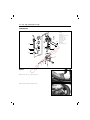
REAR AXLE SHAFT, BRAKE AND WHEEL
⑦
⑨
⑧
⑤ ⑥
②
④
G
①Rear axle shaft
②Rear brake cam
③Rear brake cam lever
④Rear brake cam lever bolt
⑤Rear brake shoe
⑥Brake shoe spring
⑦Rear wheel
⑧Rear wheel washer
⑨Rear wheel nut
H
TE
D
③
RI
①
C
O
PY
● Install the rear axle shaft ① into the crankcase by tapping its
end lightly.
● Apply engine oil on the left end of the rear axle shaft being
inserted later in the reduction rear box cover.
①
● Apply grease lightly on the rear brake cam pivot part and install
it to the crankcase.
99000-07000
Grease“G2”
● Turn to position the cam where the punched mark � on the
end face is directed toward the axis of the rear axle shaft.
Brake
cam
Apply grease
�
ENGINE 3-26
● When installing the cam lever ④ to the cam, align the punched
mark with the slit of cam lever.
Punched
mark
Slit
④
● Tighten the cam lever nut ⑤ to the specified torque.
6-9 N∙m
(0.6-0.9 kg-m, 4.5-6.5 lb-ft)
H
TE
D
Tightening torque
RI
G
● Install the brake shoes.
● Apply grease to the camshaft and pin before installing the brake
shoes.
99000-07000
Grease“G2”
O
PY
CAUTION:
Be careful not to apply too much grease to the
camshaft and pin. If grease gets on the lining, brake
effectiveness will be lost.
C
● Install the rear wheel and nut.
Tightening torque
60-90 N∙m
(6.0-9.0 kg-m, 43.5-65.0 lb-ft)
⑤
④
3-27 ENGINE
TRANSMISSION
②
⑦
⑩
⑫
⑮
⑪
①
H
TE
D
⑨
⑤
⑧
G
RI
③
⑨
⑥
⑭
⑦
⑧
PY
⑨Washer
⑩Gasket
⑪Dowel pin
⑫Gear box cover
⑬Bearing
⑭Oil seal
⑮Oil level bolt
�Oil drain bolt
②
⑬
O
①Rear axle shaft
②Circlip
③Idle shaft
④Oil drain bolt
⑤Washer
⑥Final driven gear
⑦Circlip
⑧Driveshaft
①
⑤
⑭
④
C
● Install the circlip ① on to the rear axle shaft ②.
● Assemble the idle shaft subassembly using the idle shaft ③ and
thrust washer ④, then install the subsasembly on the gear box.
②
④
③
①
● Install the final driven gear ⑤ on the rear axle shaft using the
circlip ⑥.
Thrust
�
Rounded corner
⑥
The center
Circlip
⑤
ENGINE 3-28
● Install the new bearing ⑦ to the gear box cover ⑧ with the
special tool.
09913-70610
Special tool
Bearing installer
⑦
⑧
● Apply grease to the lip of the oil seal ⑨ and install it to the
gear box cover with the special tool.
09914-05210-005
Bearing installer
Align face
Special tool
PY
RI
G
Grease“G2”
H
TE
D
Oil seal
99000-07000
O
⑨
● Install the washer ⑩, new gasket and dowel pin ⑪.
● Install the driveshaft ⑫ to the gear box cover.
C
⑪
⑫
⑪
● Apply THREE BOND NO.1215 at the hatched area shown in the
illustration and install the gear box cover ⑬ on the crankcase.
99000-31110
Three Bond No. 1215
● Tighten all the screws enenly one by one in a diagonal fashion.
Hatched
area
⑬
3-29 ENGINE
STARTER DRIVEN GEAR AND STARTER MOTOR
①Starter driven gear
②Starter motor
①
H
TE
D
②
G
● Install the starter driven gear ① over the left crankshaft end.
PY
RI
NOTE:
The convex side of hub should face outside when
installed in proper position.
O
①
C
● Install the starter motor ②.
②
ENGINE 3-30
MOVABLE DRIVEN AND CLUTCH
①Fixed driven face
②Bearing
③Circlip
④Needle roller bearing
⑤Movable driven face
⑥Oil seal
⑦Oil seal
⑧Spacer
⑨Pin
③
②
⑨
⑧
①
④
�
⑩
H
TE
D
그리스
⑦
⑥
;;
;;
;;
;;
;;
;;;;
RI
G
⑤
⑬
⑪
⑭
⑮
O
PY
⑫
⑩O-ring
⑪Spring
⑫Clutch shoe assembly
⑬Clutch shoe nut
⑭Clutch housing
⑮Clutch housing nut
�V-velt
C
● Install the bearing ② in the fixed driven face ① with the special
tool.
09943-88211
Special tool
Bearing installer
②
①
● Install the circlip ③.
③
Thrust
�
Rounded corner
3-31 ENGINE
● Install the bearing with the special tool.
09943-88210
Special tool
Bearing installer
④
● Install the new oil seals (⑤, ⑥) to the movable driven face
with the special tool.
09913-76010
Oil seal
Special tool
Bearing installer
⑥
Grease“G2”
99000-07000
⑤
G
● Install the movable driven ⑦ to the fixed driven face ⑧.
H
TE
D
● Apply grease to the lip of oil seals and groove of inside of movable driven face.
RI
NOTE:
When reinstalling the movable face to the fixed face,
make sure that the oil seal is positioned properly.
⑦
PY
⑧
C
O
● Install the pin ⑨ at three places on the driven face hub.
● Apply grease lightly to the cam part where the pins are placed.
● Position two O-ring ⑩.
⑩
Pin
Grease
⑨
Spacer
● Install the movable driven face seat ⑪.
⑪
ENGINE 3-32
● Install the spring ⑫.
● Install the clutch shoe assembly ⑬ and nut ⑭.
⑭
⑬
⑫
● Tighten the nut to the specified torque with the special tool.
Rotor holder
H
TE
D
09930-40113
40-60 N∙m
(4.0-6.0 kg-m, 29.0-43.5 lb-ft)
Tightening torque
Special tool
RI
G
● Insert the V-belt between the driven faces as deep inside as
possible while pulling the movable driven face all the way outside to provide the maximum belt clearance.
O
PY
CAUTION:
The belt should be positioned so that the arrows on
the belt periphery point the normal turning direction.
The V-belt contact face on the driven faces should be
thoroughly cleaned to be free from oil.
⑬
C
● Thoroughly clean the clutch housing ⑬ to be free from oil and
position it over the clutch shoe assembly.
● Tighten the clutch housing nut ⑭ to the specified torque with
the special tool.
09930-40113
Rotor holder
Tightening torque
40-60 N∙m
(4.0-6.0 kg-m, 29.0-43.5 lb-ft)
⑭
Special tool
3-33 ENGINE
MOVABLE DRIVE
⑥
⑤
④
⑦
③
⑧
①
H
TE
D
②
⑪
⑨
⑫
⑬
⑩
PY
RI
G
①Movable drive face
②Roller
③Movable drive plate
④Damper
⑤O-ring
⑥Movable drive face cover
⑦Spacer
⑧Fixed drive face
⑨Kick starter driven nut
⑩Kick starter driven gear
⑪Spring
⑫Spacer
⑬E-ring
O
● Install the roller ② to the movable drive face ①.
C
①
● Mount the three dampers ④ on the movable drive plate ③ and
install it on the movable drive face ⑤.
● Position the O-ring ⑥ on the movable drive face.
②
⑤
③
④
④
④
⑥
ENGINE 3-34
● Install the movable drive face cover ⑦.
NOTE:
Make sure that the movable drive plate is fully positioned
inside, or the weight roller may come off.
⑦
Spacer
● Insert the spacer.
NOTE:
Thoroughly clean the belt contact to be from oil.
H
TE
D
● Position the movable drive face subassembly on the crankshaft
as shown in the photo.
RI
G
● Install the fixed drive face ⑧.
● Tighten the nut ⑨ to the specified torque with the special tool.
Conrod holder
Tightening torque
40-60 N∙m
(4.0-6.0 kg-m, 29.0-43.5 lb-ft)
⑨
O
PY
09910-20115
⑧
C
● Fill grease in the groove provided inside sliding surface of the
kick driven gear and install it ⑩ on the end of the crankshaft.
Wipe off excess grease.
99000-07000
● Install the spring ⑪ and spacer ⑫.
⑪
Grease“G2”
⑩
⑬
⑫
● Install the E-ring ⑬.
Apply grease
⑩
⑪
⑫
⑬
3-35 ENGINE
● Continue turning the fixed drive face ⑭ by hand until the belt is
seated in and both the drive and driven faces ⑮ will move
together smoothly without slip.
● Fill the final gear box with engine oil up to the level hole.
Oil Capacity
⑮
90 ml
● Tighten the oil level bolt to the specified torque.
⑭
9-15 N∙m
(0.9-1.5 kg-m, 4.5-11.0 lb-ft)
Tightening torque
KICK STARTER
H
TE
D
⑤
⑧
②
RI
⑥
⑦
O
①Kick starter lever
②Kick starter shaft
③Kick starter shaft spring
④Circlip
⑤Crankcase cover LH
⑥Gasket
⑦Clutch cover
⑧Screw
①
G
④
PY
③
C
● Apply grease lightly on the rolling surface and install it on the
crankcase cover.
99000-07000
①
Grease“G2”
● Position the kick starter shaft return spring and hook the spring
end on the crankcase cover boss ①.
● Install the dowel pin and crankcase cover ②.
②
ENGINE 3-36
● Install the clutch cover and kick starter lever ①.
①
NOTE:
Install the kick starter lever as shown in the illustration.
13�
● Tighten the kick starter lever bolt to the specified torque.
8-12 N∙m
(0.8-1.2 kg-m, 6.0-8.5 lb-ft)
H
TE
D
Tightening torque
④
⑥
C
⑤
②
O
⑦
PY
RI
G
PISTON
Apply engine oil
①
⑨
⑧
③
①Needle roller bearing
②Piston
③Piston ring
④1st ring
⑤2nd ring
⑥Expender ring
⑦Circlip
⑧Piston pin
⑨Cylinder gasket
⑩Cylinder
⑪Cylinder head gasket
⑫Cylinder head
⑬Cylinder head nut
⑩
⑦ ⑬
⑪
⑫
3-37 ENGINE
● Install the piston rings on the piston.
∙1st - Keystone ring
∙2nd - Rectangular ring
�Expander ring
NOTE:
Position the ring so that the marking is on upside.
Locating pin
H
TE
D
● It is extremely important that, when the piston is fed into the
cylinder, each ring in place should be so positioned as to hug
the locating pin as shown in the illustration.
CORRECT
INCORRECT
G
● Apply engine oil on the piston pin and install the piston to the
conrod.
PY
RI
NOTE:
The arrow mark ① on the piston head should point
the exhaust side.
②
C
O
● The circlip should be mounted in such a position ② that the
mating ends of the circlip do not coincide with the groove portion of the piston.
● Position the cylinder base gasket.
● Apply engine oil on the piston and cylinder wall surfaces and
install the cylinder over the piston carefully.
①
● Tighten the cylinder head nut to the specification.
Tightening torque
8-12 N∙m
(0.8-1.2 kg-m, 6.0-8.5 lb-ft)
Outside
ENGINE 3-38
OIL PUMP AND INTAKE
②
①
H
TE
D
Apply grease
G
● Apply grease to the oil pump driven gear ① and install it to the
crankcase.
①
Grease“G2”
O
PY
RI
99000-07000
①Oil pump driven gear
②Oil pump
C
● Install the oil pump ② and tighten it to the specified torque.
Tightening torque
3-5 N∙m
(0.3-0.5 kg-m, 2.0-3.6 lb-ft)
● Install the gaskets (③, ④) and intake pipe ⑥ with reed valve
⑤ to the crankcase.
⑥
④
⑤
③
②
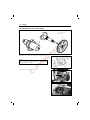
3-39 ENGINE
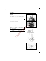
MAGNETO
①Stator
②Key
③Magneto rotor
④Nut and washer
⑤Fan case
⑥Cooling fan
⑦Fan cover
④
③
②
①
⑥
H
TE
D
⑤
O
PY
RI
G
⑦
C
● Degrease the tapered portion of the crankshaft and also the
magneto rotor.
● Install the stator ①.
● Install the key ②.
● Install the rotor ③.
①
● Apply THREAD LOCK“1324”to the rotor nut ④ and tighten it to
the specified torque with the special tool.
99000-32030
THREAD LOCK“1324”
09930-40113
Rotor holder
Tightening torque
35-45 N∙m
(3.5-4.5 kg-m, 25.5-31.0 lb-ft)
②
④
③
ENGINE 3-40
● Install the fan case ⑤.
● Install the magneto lead wire and starter motor lead wire.
⑤
● Install the cooling fan ⑥.
H
TE
D
⑥
⑦
PY
RI
G
● Install the cooling fan cover ⑦.
O
MUFFLER
C
● Tighten the exhaust pipe bolts ① and muffler mounting bolts ②
to the specified torque.
Tightening torque
8-12 N∙m
(0.8-1.2 kg-m, 6.0-8.5 lb-ft)
②
①
FUEL AND LUBRICATION SYSTEM
CONTENTS
CARBURETOR
4- 1
REMOVAL
4- 1
DISASSEMBLY
4- 2
INSPECTION
4- 4
REASSEMBLY AND REMOUNTING
4- 4
H
TE
D
FUEL TANK
REMOVAL
REMOUNTING
C
O
PY
RI
G
OIL PUMP
4- 6
4- 6
4- 7
4- 8
4
4-1 FUEL AND LUBRICATION SYSTEM
CARBURETOR
④
⑪
⑤
⑫
③
②
⑩
⑨
C
O
PY
RI
G
⑧
REMOVAL
⑦
H
TE
D
⑥
● Remove the side cover. (Refer to page 6-3)
● Remove the absorber mounting lower bolt.
①
①Carburetor chamber
②Float
③Main jet
④Throttle stop screw
⑤Needle jet
⑥Needle valve
⑦Pilot air screw
⑧Throttle valve
⑨Jet needle
⑩E-ring
⑪Spring
⑫Thermoelement
FUEL AND LUBRICATION SYSTEM 4-2
● Remove the carburetor top cap ①, and disconnect the throttle
cable ②.
②
①
● Disconnect the carburetor hoses and oil hose.
Vacuum hose ③.
Oil hose ④.
Fuel hose ⑤.
H
TE
D
⑤
③
④
C
DISASSEMBLY
O
PY
RI
G
● Remove the careburetor by loosening the mounting bolts ⑥ and
clamp screw ⑦.
● Remove the thermoelement assembly.
CAUTION:
Do not attempt to disassemble the thermoelement
assembly.
It is not serviceable.
⑥
⑦
4-3 FUEL AND LUBRICATION SYSTEM
● Remove the float chamber ①.
①
● Remove the float ③ by removing the screw and pin ②.
②
③
H
TE
D
SCREW
G
● Remove the needle valve ④.
PY
RI
④
O
● Remove the throttle stop screw ⑤ and pilot air screw ⑥.
C
NOTE:
When removing the pilot air screw, record the revolutions until tighten completly.
⑤
⑥
⑥
⑤
● Remove the main jet ⑦ and needle jet ⑧.
⑦,⑧
⑦
⑧
FUEL AND LUBRICATION SYSTEM 4-4
INSPECTION
Inspect the valve surface
for worn.
Check following items for any damage or clogging.
● Pilot jet
● Main jet
● Pilot air screw
● Needle jet air bleeding hole
● Float
● Gasket
● Pilot outlet and bypass holes
Foreign
matter
NEEDLE VALVE INSPECTION
H
TE
D
If foreign matter is caught between the valve seat and the needle,
the gasoline will continue flowing and cause it to overflow. If the
seat and needle are worn beyond the permissible limits, similar
trouble will occur. Conversely, if the needle sticks, the gasoline will
not float chamber. Clean the float chamber and float parts with
gasoline. If the needle is worn as shown in the illustration, replace
it together with a valve seat. Clean the fuel passage of the mixing
chamber with compressed air.
RI
PY
③ ④ ①
②
O
● Reassemble following items.
①Pilot air screw
②Throttle stop screw
③Main jet
④Needle jet
G
REASSEMBLY AND REMOUNTING
C
● Install the needle ⑤ and float ⑥ on the carburetor body.
⑥
⑤
● Install the float pin and tightened the screw ⑦.
● Install the gasket and float chamber.
⑦
4-5 FUEL AND LUBRICATION SYSTEM
● Install the thermoelement assembly.
③
O
PY
RI
G
● Install the vacuum hose ①, oil hose ② and fuel hose ③.
H
TE
D
● Install the carburetor assembly.
C
● Install the carburetor top cap.
②
①
FUEL AND LUBRICATION SYSTEM 4-6
FUEL TANK
①
REMOVAL
● Remove the side covers. (Refer to page 6-3)
● Remove the rear center cover ①.
● Disconnect the fuel hose ②.
H
TE
D
NOTE:
To prevent fuel flow, connect the suitable cap to the
fuel tank outlet.
②
③
O
PY
RI
G
● Disconnect the oil gauge lead wire ③.
C
● Remove the shock absorber mounting lower bolt.
● Remove the rear fender bolts, then take off the rear fender.
CLEANING
Dust from the fuel tank tends to bulid up in the fuel filter which,
when the fuel filter has been neglected for a long period, inhibits
the flow of fuel.
Remove the dust from, the fuel filter ① using compressed air.
①
4-7 FUEL AND LUBRICATION SYSTEM
REMOUNTING
Remount the fuel tank in the reverse of removal.
①Fuel tank
②Fuel level gauge
③Fuel level gauge cap
④Fuel tank cap
⑤Vacuum hose
⑥Inlet hose
⑦Outlet hose No.1
⑧⑨Cushion
⑩Fuel strainer
⑪Outlet hose No.2
③
②
④
H
TE
D
;yy; ;y
①
PY
RI
G
⑨
⑥
C
O
⑤
⑦
⑪
⑩
⑧
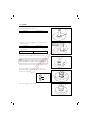
FUEL AND LUBRICATION SYSTEM 4-8
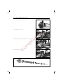
OIL PUMP
AIR BLEEDING
Whenever evidence is noted of some air having leaked into the oil
pipe from the oil tank in a machine brought in for servicing, or if
the oil pump has to be removed for servicing, be sure to carry out
an air bleeding operating with the oil pump in place before returning
the machine to the user.
To bleed air, hold the machine in standstill condition. Loosen the
screw ① to let out air and after making sure that the trapped air
has all been bled, tighten the screw good and hare.
CHECKING OIL PUMP
RI
G
H
TE
D
Use the special tool, to check the pump for capacity by measuring
the amount of oil the pump draws during the specified interval.
● Remove the left side cover.
● Have the tool filled with HYOSUNG HYPOL OIL and connect it to
the suction side of the pump.
● Run the engine at 3000 r/min.
● Holding engine speed at the same 3000 r/min., let the pump
draw for 5 minutes. For this operation, the reading taken on the
device should be 0.9~1.1 ml.
CCI oil gauge
PY
09900-21602
0.9-1.1 ml at 3000 r/min.
for 5 minutes.
CAUTION:
O
Oil discharge amount
points.
C
During this inspection, strictly follow the following
� The machine should be rested on the center stand.
� Do not touch the rear wheel while running the
engine.
①
ELECTRICAL SYSTEM
CONTENTS
ELECTRICAL PARTS
5- 1
IGNITION/CHARGING SYSTEM
5- 2
5- 2
STATOR COILS
5- 3
REGULATOR/RECTIFIER
5- 3
STARTER SYSTEM
STARTER MOTOR INSPECTION
STARTER RELAY INSPECTION
FUEL LEVEL GAUGE
G
OIL LEVEL CHECK LIGHT
H
TE
D
IGNITION COIL
RI
THERMOELEMENT
SWITCHES
C
O
PY
BATTERY
5- 4
5- 5
5- 5
5- 6
5- 7
5- 8
5- 9
5-10
5
5-1 ELECTRICAL SYSTEM
ELECTRICAL PARTS
①
②
③
④
⑤
①
Ignition coil
Thermolement assembly
Trunk box lamp
Fuel level gauge
Oil level gauge
②
Turn signal relay
H
TE
D
Key set
G
Starting motor relay
③
RI
Rectifier
PY
M.F battery
C.D.I Unit
C
O
Horn
④
⑤
ELECTRICAL SYSTEM 5-2
IGNITION/CHARGING SYSTEM
Stator
Ignition
coil
Regulator/Rectifier
CDI
unit
Spark
plug
Lighting
switch
H/L
T/L
Battery
12V 3AH
(MF)
M/L
H
TE
D
Engine stop
switch
12V
15W×2
IGNITION COIL
12V
5W
12V
3.4W×2
09900-28106
PY
RI
G
● Check the ignition coil with electro tester.
● Test the ignition coil for sparking performance. Test connection is
as indicated. Make sure that the three-needle sparking distance
is at least 8mm. Test it at least for 5 minutes.
Electro tester
8 mm
O
STD spark performance
R
C
Y
B
B
Spark
● Check the ignition coil with pocket tester.
09900-25002
Pocket tester
B/R
IGNITION COIL RESISTANCE
Primary
Secondary
W/L-Ground
Approx. 0.15-0.28Ϊ
Plug cap-Ground
Approx. 14-20㏀
그라운드
플러그 캡
5-3 ELECTRICAL SYSTEM
STATOR COILS
● Using a pocket tester, measure the resistance between the lead
wire and ground. If the resistance checked is incorrect, replace
the coil.
Y/W
W/R
B/R
Standard resistance
Lighting
0.6-1.4Ϊ
Charging
0.6-1.4Ϊ
Exciting
180-230Ϊ
Ground
Ground
Ground
CHARGING OUTPUT CHECK
H
TE
D
Start the engine and keep it running at 5000 r/min with lighting
switch turned ON.
Measure the DC voltage between the battery terminal � and �
with a pocket tester.
If the tester reads under or over following specification, check the no-lead
performance or replace the regulator/rectifier.
NOTE:
When making this test, be sure that the battery is in
fully-charged condition.
Pocket tester
09900-26006
Tachometer
G
09900-25002
14-15V at 5000 r/min
RI
STD charging output
NO-LOAD PERFORMANCE
C
O
PY
● Disconnect the magneto lead wire coupler.
● Start the engine and keep it running at 5000 r/min.
● Using a pocket tester, measure the AC voltage between the
White with Red tracer white lead wire and ground. If the
tester reading is as follows, magneto is in good condition.
STD No-load performance
More than 100 V(AC)at
5000 r/min
REGULATOR/RECTIFIER
● Disconnect the coupler.
● Using the pocket tester(×1㏀ range), measure the resistance between the terminals as shown in the following table.
If the resistance checked is incorrect, replace the
regulator/rectifier.
09900-25002
Pocket tester
� Probe of tester to:
Unit: Approx.㏀
①
①
②
③
④
50-230
∞
∞
� Probe of tester to:
②
③
50-260
∞
∞
∞
∞
10-100
④
∞
∞
∞
ELECTRICAL SYSTEM 5-4
STARTER SYSTEM
DESCRIPTION
The starter system is shown in the diagram below: namely, the starter motor, relay, starter switch
and battery. Depressing the starter button (on the right handlebar switch box) while squeezing the
front or rear brake lever energizes the relay, causing the contact points to close which connects the
starter motor to the battery.
Starter relay
R
Fuse
R/W
IG switch
Starter button
H
TE
D
Y/G
Point
Brake switch
Starter
motor
W/B
RI
G
Battery
PY
STARTER MOTOR REMOVAL AND DISASSEMBLY
O
Remove the starter motor.
Disassemble the starter motor as shown in the illustration.
C
①
②
③
④
⑤
①
②
③
④
⑤
Holder
Pinion gear assembly
Brush holder assembly
Amateur
Starting motor cover
5-5 ELECTRICAL SYSTEM
STARTER MOTOR INSPECTION
CARBON BRUSHES
When the brushes are worn, the motor will be unable to procedure sufficient torque, and the engine will be difficult to
turn over. To prevent this, periodically inspect the length of
the brushes and replace them when they are too short or
chipping.
Service Limit
4mm(0.16in)
COMMUTATOR
Service Limit
4mm(0.16in)
ARMATURE COIL
H
TE
D
If the commutator surface is dirty, starting performance will
decrease. Polish the commutator with #400 or similar fine emery
paper when it is dirty. After polishing wipe the commutator with a
clean dry cloth.
Measure the commutator under cut ①.
PY
RI
G
Using the pocket tester, check the coil for open and ground
by placing probe pins on each commutator segment and rotor
core (to test for ground)and on any two segments at various
places (to test for open), with the brushes lifted off the
commutator surface.
If the coil is found to be open-circuited or grounded, replace
the armature. Continuous use of a defective armature will
cause the starter motor to suddenly fail.
Pocket tester
O
09900-25002
STARTER RELAY INSPECTION
C
● Disconnect the starter relay lead wire coupler.
Check the coil for “open”, “ground” and ohmic
resistance. The coil is in good condition, if the
resistance is as follows.
09000-25002
Pocket tester
STD resistance
0-70Ϊ
ELECTRICAL SYSTEM 5-6
FUEL GAUGE
Fuel level gauge
O
B/W
Y/B
H
TE
D
Fuel tank
FUEL LEVEL METER/GAUGE
FUEL METER INSPECTION
PY
RI
G
To test the Fuel Meter two different checks may be used.
The first, and simplest test will tell if the meter is operating but will
not indicate the meters accuracy throughout the range. To perform
this test, lift the seat and remove the right frame cover, then disconnect the B/W and Y/B lead connector of the fuel gauge sending
unit. Connect a jumper wire between B/W and Y/B wires coming
from the main wiring harness. With the ignition switch turned ON,
the fuel meter should indicate“F”.
C
O
The second test will check the accuracy of the meter in the full and
empty positions. Connect a 90-ohm resistor between the Y/B and
B/W lead wires. The fuel meter is normal if its pointer indicates the
E(empty) position when the specified voltage is applied to the circuit
and if its pointer indicates the F(full) position when the resistor is
changed to 10 ohms.
If either one or both indications are abnormal, replace the fuel
meter with a new one.
5-7 ELECTRICAL SYSTEM
FUEL GUAGE SENDING UNIT INSPECTION
● Disconnect the lead wires coming out of the fuel gauge and
check resistance of each position.
● If the resistance measured is incorrect, replace the fuel gauge
assembly with a new one.
● The relation between the position of the fuel gauge float and
resistance is shown in the following table.
Float position
F(Full)
1/2
E(Empty)
Resistance
Approx. 10Ϊ
Approx. 38Ϊ
Approx. 90Ϊ
Full
1/2
Empty
H
TE
D
OIL LEVEL CHECK LIGHT
Oil level check light
G
Oil
level switch
PY
RI
IG switch
C
O
Battery
OIL LEVEL SWITCH INSPECTION
Check the oil level switch for continuity between the lead wire. If the
tester does not show the value of 0-1 ohm when the switch ring is
in bottom position, file the contact surface or replace the unit.
09900-25002
Switch
�
Pocket tester
�
ELECTRICAL SYSTEM 5-8
OIL LEVEL CHECK LIGHT INSPECTION
Disconnect the L/W and B/W lead connector ① of the oil level
check light.
Connect a jumper wire between L/W and B/W wires coming from
the main wiring harness. With the ignition switch turned ON, the oil
level check light should flash.
If there is no flash, check the wiring harness continuity and the bulb
blown out.
①
B/R
H
TE
D
THERMOELEMENT
R
Y/W R/W
�
�
REGURATOR/RECTIFIER
Battery
MAGNETO
RI
G
PTC
PY
INSPECTION
C
O
● Disconnect the thermoelement coupler.
● Connect the thermoelement coupler ① to a 12V battery and
touch the thermoelement ② to check the temperature being
raised.
The thermoelement ② should become heated to a temperature
more than that of human body within five minutes. If not,
replace with new one.
NOTE:
This check should be carried out when the carburetor
is cold.
①
②
5-9 ELECTRICAL SYSTEM
SWITCHES
LIGHTING SWITCH
Inspect each switch for continuty with the pocket tester
referring to the chart. If it is found any abnormality,
replace the repective switch assembly with new one.
ON
Gr
YW
○
○
OFF
STARTER BUTTON
BW
YG
○
○
ON
WIRE COLOR
FRONT AND REAR BRAKE LIGHT SWITCH
PY
O
O
WB
○
○
H
TE
D
ON
OFF
DIMMER SWITCH
G
W
Y
Gr
○
○
○
○
LO
HI
RI
Black
Green
Gray
Light blue
Light green
Orange
Red
White
Yellow
Black with Red tracer
Black with White tracer
White with Black tracer
Yellow with white tracer
TURN SIGNAL LIGHT SWITCH
Lg
L
B
Sb
○
○
∙
R
C
B
G
Gr
Sb
Lg
O
R
W
Y
B/R
B/W
W/B
Y/W
OFF
○
○
HORN BUTTON
ON
BW
G
○
○
OFF
IGNITION SWITCH
LOCK
OFF
ON
BW
BR
○
○
○
○
R
O
○
○
ELECTRICAL SYSTEM 5-10
BATTERY
SPECIFICATION
Type designation
Capacity
Standard electrolyte S.G.
YTX4L-BS
12V, 3AH/10HR
1.32 at 20 ℃(68℉)
INITIAL CHARGING
FILLING ELECTROLYTE
H
TE
D
● Remove the aluminum tape ① sealing the battery electrolyte
filler holes.
G
● Remove the caps ②.
O
PY
RI
NOTE:
After filling the electrolyte completely, use the
removed cap ② as the sealed caps of battery-filler
holes.
Do not remove or pierce the sealed areas ③ of the
electrolyte container.
C
● Insert the nozzels of the electrolyte container into the battery、s
electrolyte filler holes, holding the container firmly so that it does
not fall. Take precaution not to allow any of the fluid to spill.
● Make sure air bubbles are coming up each electrolyte container,
and leave in this position for about more than 20 minutes.
5-11 ELECTRICAL SYSTEM
NOTE:
If no air bubbles are coming up from a filler port, tap the
bottom of the two or three times.
Never remove the container from the battery.
H
TE
D
● After confirming that the electrolyte has entered the battery
completely, remove the electrolyte containers from the battery.
Wait for around 20 minutes.
● Insert the caps into the filler holes, pressing in firmly so that the
top of the caps do not protrude above the upper surface of the
battery、s top cover.
CAUTION:
Never use anything except the specified battery.
Once install the caps to the battery, do not remove the
caps.
RI
G
● Using HYOSUNG pocket tester, measure the battery voltage. The tester
should indicate more than 12.5-12.6 V(DC)as shown in the Fig. If the
battery voltage is lower than the specification, charge the battery with
a battery charger.
C
SERVICING
O
PY
NOTE:
Initial charging for a new battery is recommended if
two years have elapsed since the date of manufacture.
Visually inspect the surface of the battery container. If any signs of
cracking or electrolyte leakage from the sides of the battery have
occurred, replace the battery with a new one. If the battery terminals are found to be coated with rust or an acidic white powdery
substance, then this can be cleaned away with sandpaper.
ELECTRICAL SYSTEM 5-12
RECHARGING OPERATION
● Using the pocket tester, check the battery voltage. If the voltage
reading is less than 12.0V(DC), recharge the battery with a battery charger.
CAUTION:
When recharging the battery, remove the battery from the
motorcycle.
NOTE:
Do not remove the sealing cap off the battery top while
recharging.
0.4A for hours or
4.0A for half an hour
H
TE
D
Recharging time
CAUTION:
Be careful not to allow the charging current to exceed 4A
at any time.
C
O
PY
RI
G
● After recharging, wait for more than 30 minutes and check the
battery voltage with a pocket tester.
● If the battery voltage is less than 12.5V, recharge the battery
again.
● If the battery voltage is still less than 12.5V after recharging,
replace the battery with a new one.
● When a battery is left for a long term without using, it is subject
to discharge. When the motorcycle is not used for more than 1
month(especially during the winter season), recharge the battery
once a month at least.
CHASSIS
CONTENTS
HANDLE BAR COVERS
6- 1
REMOVAL
6- 2
REMOUNTING
6- 2
LEG SHIELD AND SIDE COVERS
6- 3
REMOVAL
6- 4
REMOUNTING
6- 7
6- 8
REMOVAL AND DISASSEMBLY
INSPECTION
H
TE
D
FRONT WHEEL
REASSEMBLY AND REMOUNTING
FRONT BRAKE
BRAKE PAD REPLACEMENT
CALIPER INSPECTION
RI
CALIPER REASSEMBLY
G
CALIPER REMOVAL AND DISASSEMBLY
6- 8
6-10
6-10
6-13
6-13
6-14
6-15
6-15
6-16
DISC PLATE INSPECTION
6-16
MASTER CYLINDER REMOVAL AND DISASSEMBLY
6-16
MASTER CYLINDER INSPECTION
6-18
MASTER CYLINDER REASSEMBLY AND REMOUNTING
6-18
O
PY
DISC PLATE REMOVAL AND DISASSEMBLY
C
FRONT FORK
6-19
REMOVAL AND DISASSEMBLY
6-19
INSPECTION
6-21
REASSEMBLY AND REMOUNTING
6-21
STEERING
6-22
REMOVAL AND DISASSEMBLY
6-22
INSPECTION
6-23
REASSEMBLY AND REMOUNTING
6-23
REAR WHEEL AND BRAKE
6-25
REMOVAL AND DISASSEMBLY
6-25
INSPECTION
6-25
REASSEMBLY AND REMOUNTING
6-26
6
4 ㎜
5 ㎜
Tightening torque
10~20 ㎏∙㎝
20~40 ㎏∙㎝
Tightening torque: 10~20 ㎏∙㎝
Headlight
Handle bar
RI
G
Throttle grip
H
TE
D
Tightening torque: 15~25 ㎏∙㎝
PY
O
C
Handlebar front cover
Handle rear cover
6-1 CHASSIS
HANDLEBAR COVERS
CHASSIS 6-2
REMOVAL
HANDLEBAR FRONT COVER
HANDLEBAR REAR COVER
O
PY
RI
G
H
TE
D
● Remove the handlebar front cover by removing the mounting
screws and disconnecting the lead wires.
C
● Disconnect the lead wire couplers and speedometer cable.
● Remove the handlebar rear cover by removing the mounting
screws.
REMOUNTING
● Remount the handlebar covers in the reverse order of removal.
4 ㎜
5 ㎜
6 ㎜
Tightening torque
10~20 ㎏∙㎝
20~40 ㎏∙㎝
40~70 ㎏∙㎝
Front lower shield
Side leg shield, L
Side leg shield, R
Mat floor
H
TE
D
Battery cover
Leg shield cover
G
RI
PY
O
C
Front upper leg shield
Side cover, L
Side cover, R
Center cover
6-3 CHASSIS
LEG SHIELD AND SIDE COVERS
CHASSIS 6-4
REMOVAL
FRONT LEG SHIELD UPPER
● Loosen the mounting screws.
H
TE
D
● Remove the front leg shield upper by pull out it forward.
FRONT LEG SHIELD LOWER
C
O
PY
RI
G
● Loosen the mounting screws.
● Remove the front leg shield lower.
6-5 CHASSIS
REAR CARRIER
● Open the seat.
● Remove the rear carrier by removing the bolts and screw.
RIGHT SIDE COVER, RIGHT SIDE LEG SHIELD
C
O
PY
RI
G
H
TE
D
● Loosen the mounting screws.
● Remove the right side cover and right side leg shield at the
same time.
Side cover
Side leg shield
CHASSIS 6-6
LEFT SIDE COVER, LEFT SIDE LEG SHIELD
O
PY
RI
G
H
TE
D
● Loosen the mounting screws.
C
● Remove the handle grip ① by removing the bolts.
①
● Remove the left side cover and left side leg shield at the same
time.
Side cover
side leg shield
6-7 CHASSIS
REAR CENTER COVER
● Remove the rear center cover by removing the bolts.
COVER LEG SHIELD REAR AND LEL SHIELD REAR
H
TE
D
● Remove the ignition cap.
● Remove the battery cover by removing the screw.
Battery cover
C
O
PY
RI
G
● Loosen the screw and bolts.
● Remove the cover leg shield ① rear and leg shield rear ② at
the same time.
REMOUNTING
● Remount the leg shield and side covers in the reverse orders of
removal.
①
②
CHASSIS 6-8
FRONT WHEEL
①
Item
①
⑩
②
③
Tightening torque
Nㆍm
㎏ㆍm
lbㆍft
33-52
3.3-5.2 24.0-37.5
18-28
1.8-2.8 13.0-20.0
④
H
TE
D
⑥
⑩
RI
PY
O
C
①Front axle nut
②Speedometer gear box
③Wheel bearing(R)
④Spacer
⑤Wheel bearing(L)
⑥Disc plate
⑦Spacer
⑧Oil seal
⑨Front axle shaft
⑩Disc bolt
G
⑤
REMOVAL AND DISASSEMBLY
● Remove the front brake caliper by removing the mounting bolts.
NOTE:
Do not operate the front brake lever while dismounting the caliper.
● Remove the front axle nut.
● Support the motocycle by jack or wooden block.
● Remove the front wheel by removing the front axle shaft.
⑦
⑧
⑨
6-9 CHASSIS
● Remove the disc plate ① by removing the bolts.
①
● Remove the spacer.
H
TE
D
②
G
● Remove the dust seal ③ with the special tool.
Oil seal remover
O
PY
RI
09913-50121
C
● Drive out the both bearing with the special tool in the following
procedures.
● Insert the adapter into the bearing.
● After inserting the wedge bar from the opposit side, lock the
wedge bar in the slit of the adapter.
● Drive out the bearing by knocking the wedge bar.
09941-50110
Bearing remover
CAUTION:
The removed dust seal and bearing should be
replaced with new ones.
③
CHASSIS 6-10
INSPECTION
WHEEL RIM
Make sure that the wheel rim runout does not exceed the service
limit when checked as shown.
An excessive runout is usually due to worn or loose wheel bearings
and can be reduced by replacing the bearings. If bearing replacement fails to reduce the runout, replace the wheel.
Service limit
(Axle and Radial)
3 .0 mm(0.12 in)
TIRE
TIRE DEPTH SERVICE LIMIT
Front & Rear
1.6 mm(0.064 in)
Special tool
H
TE
D
Inspect the tires for wear and damage;and check the tire tread
depth as shown. Replace a badly worn or damaged tire. A tire with
its tread worn down to the limit(in terms of tread depth)must be
replaced.
Check the tire pressure, and examine the value for evidence of air
leakage.
G
TIRE DEPTH SERVICE LIMIT
NORMAL RIDING
SOLD RIDING
DUAL RIDING
kPa
kg/㎠
kPa
kg/㎠
125
1.25
-
-
200
2.00
-
-
RI
COLD INFLATION
TIRE PRESSURE
O
PY
FRONT
REAR
REASSEMBLY AND REMOUNTING
C
Reassemble and remount the front wheel in the reverse order
diassembly and removal, and also carry out the following steps.
ell
S h
A valnia
WHEEL BEARING
3
● Apply grease to the bearings before installing.
I ndustrial e
purpos
M ulti-
99000-07C00
Grease“G2”
● Install the wheel bearings by using the special tool.
09924-84520
Bearing installer
CAUTION:
First install the wheel bearing for left side.
ase
G re
6-11 CHASSIS
Right side
Left side
Special tool
Bearing(R)
Spacer
Clearance
Bearing(L)
Bearing(L)
OIL SEAL
● Install the oil seal ① with the special tool.
①
Oil seal installer
H
TE
D
09922-55131
O
PY
RI
G
● Install the spacer ②.
DISC PLATE
C
● Install the disc plate and tighten them to the specified torque.
Tightening torque
18-28 Nㆍm
(1.8-2.8 kgㆍm, 13-20 lb-ft)
②
CHASSIS 6-12
SPEEDOMETER GEAR BOX
● When installing the speedometer gear box, align the two drive
pawls � with the two recesses � of the wheel hub.
CAUTION:
After touching the speedometer gear box � to the stopper
�, tighten the axle shaft.
�
�
�
H
TE
D
�
● Tighten the front axle nut to the specified torque.
G
FRONT WHEEL
33-52 Nㆍm
(3.3-5.2 kgㆍm, 24-38 lbㆍft)
O
PY
RI
Tightening torque
C
● Tighten the caliper mounting bolts to the specified torque.
Tightening torque
18-28 Nㆍm
(1.8-2.8 kgㆍm, 13-20 lbㆍft)
6-13 CHASSIS
FRONT BRAKE
⑤
①
Apply silicone grease
②
⑥
H
TE
D
③
④
⑦
⑧
⑨
Item
①
③
⑥
Tightening
Nㆍm
8-12
20-25
6-9
torque
kgㆍm
0.8-1.2
2.0-2.5
0.6-0.9
O
PY
RI
G
①Master cylinder bolt
②Master cylinder
③Brake hose union bolt
④Brake hose
⑤Pad
⑥Air bleeder valve
⑦Dust seal
⑧Piston
⑨Piston seal
⑩Caliper
⑩
BRAKE PAD REPLACEMENT
C
● Remove the caliper by removing the mounting bolts ①.
NOTE:
Do not operate the front brake lever while dismounting the
caliper.
①
● Remove the brake pads ②.
CAUTION:
Replace the brake pads as a set, otherwise braking performance will be adversely affected.
②
lb-ft
6.0-8.5
14.5-18.0
4.5-6.5
CHASSIS 6-14
CALIPER REMOVAL AND DISASSEMBLY
● Remove the brake hose and catch the brake fluid in a suitable
receptacle.
CAUTION:
Never re-use the brake fluid left over from the last servicing
and stored long periods.
● Remove the caliper.
● Remove the brake pads.
● Remove the pad holder ① and spring ②.
②
O
PY
RI
G
H
TE
D
①
C
● Place a rag over the piston to prevent popping up. Force out the
piston with a air gun.
CAUTION:
Do not use high pressure air to prevent piston damage.
● Remove the dust seal ③ and piston seal ④.
④
③
6-15 CHASSIS
CALIPER INSPECTION
Inspect the caliper cylinder bore wall for nicks, scratches or other
damage.
Inspect piston for damage and wear.
H
TE
D
Inspect each rubber part for damage and wear.
CALIPER REASSEMBLY
G
RI
O
PY
{
CAUTION:
Wash the caliper components with fresh brake fluid
before reassembly. Never use cleaning solvent or
gasoline to wash them. Apply brake fluid to the
caliper bore and piston to be inserted into the bore.
Apply grease
{
Reassemble and remount the caliper in the reverse order of removal
and disassembly, and also carry out the following steps.
C
● Apply silicone grease to the caliper holder.
99000-25100
Silicone grease
● Tighten the each bolts.
Item
③
④
Nㆍm
18-28
20-25
kgㆍm
1.8-2.8
2.0-2.5
lb-ft
13-20
14-18
WARNING:
Bleed the air from brake fluid circuit after reassembling caliper(See page 2-8)
③
④
CHASSIS 6-16
DISC PLATE REMOVAL AND DISASSEMBLY
● Remove the front wheel(Refer to page 6-8)
● Remove the disc plate(Refer to page 6-9)
● Install the disc plate(Refer to page 6-11)
DISC PLATE INSPECTION
Service Limit
09900-20205
3.5 mm(0.14 in)
Micrometer(0-25 mm)
H
TE
D
● Check the disc for wear with a micrometer. Its thickness can be
checked with disc and wheel in place. Replace the disc if the
thickness exceeds the service limit.
RI
G
● With the disc mounted on the wheel, check the disc for face
runout with a dial gauge as shown. Replace the disc if the
runout exceeds the service limit.
0.3 mm(0.012 in)
Dial gauge(1/100 mm)
Magnetic stand
O
PY
Service Limit
09900-20606
09900-20701
C
MASTER CYLINDER REMOVAL AND
DISASSEMBLY
● Remove the handlebar cover(Refer to page 6-1)
● Disconnect the front brake light switch lead wires.
● Place a cloth underneath the union bolt on the master cylinder
to catch spilled drops of brake fluid. Unscrew the union bolt and
disconnect the brake hose/master cylinder joint.
CAUTION:
Completely wipe off any brake fluid adhering to any
part of motorcycle. The fluid reacts chemically with
paint, plastics, rubber materials, etc.
6-17 CHASSIS
● Remove the master cylinder.
● Remove the brake lever ① and brake switch ②.
②
H
TE
D
①
③
O
PY
RI
G
● Remove the dust boot ③.
C
● Remove the circlip ④ with the special tool.
09900-06108
Snapring pliers
● Remove the piston/primary cup with return spring ⑤.
● Remove the reservoir cap ⑥ and diaphragm ⑦.
● Drain brake fluid.
④
⑥
}
⑦
⑤
CHASSIS 6-18
MASTER CYLINDER INSPECTION
Inspect the master cylinder bore for any scratches or other damage.
Inspect the piston surface for scratches or other damage.
Inspect the primary cup and dust boot for wear or damage.
MASTER CYLINDER REASSEMBLY AND REMOUNTING
Reassemble and remount the master cylinder in the reverse
order of removal and disassembly, and also carry out the
following steps.
H
TE
D
Boot
CAUTION:
Wash the master cylinder components with fresh brake fluid
before reassembly. Never use cleaning solvent or gasoline
to wash them.
Apply brake fluid to the cylinder bore and all the internals
to be inserted into the bore.
Circlip
Spring
Piston
Primary cap
Second cap
RI
G
● Reassemble and remount the master cylinder.(Refer to page 613)
● When remounting the master cylinder on the handlebar, first
tighten the clamp bolt for upside.
C
O
PY
CAUTION:
Bleed air after remounting the master cylinder.(Refer to
page 2-8)
UP
△
6-19 CHASSIS
FRONT FORK
Item
③
⑥
⑫
⑦
③
Tightening torque
Nㆍm
kgㆍm
35-55
3.5-5.5
25-35
2.5-3.5
20-26
2.0-2.6
lb-ft
22.5-40.0
16.0-25.5
14.5-18.8
⑧
⑨
⑩
⑪
⑥
H
TE
D
①
②
④
G
⑫
O
PY
RI
⑤
REMOVAL AND DISASSEMBLY
C
● Remove the front leg shield(Refer to page 6-3).
● Remove the front brake caliper by removing the mounting bolts.
NOTE:
Do not operate the front brake lever while dismounting the caliper.
● Remove the front axle nut.
● Remove the motorcycle by jack or wooden block.
● Remove the front wheel by removing the front axle shaft.
①Steering stem
②Under bracket
③Fork bolt
④Cushion spring
⑤Pipe seat
⑥Fork lower clamp bolt
⑦Fork pipe
⑧Dust boot
⑨Stopper ring
⑩Oil seal
⑪Bottom case
⑫Socket bolt
CHASSIS 6-20
● Loosen the front fork bolt, then draw out the fork spring.
● Loosen the front fork lower clamp bolts.
O
PY
RI
G
● Remove the scoket bolt ① with the hexagon wrench.
● Seperate the fork pipe ② and pipe seat ③.
H
TE
D
● Invert the fork and stroke it several times to remove the oil.
● Hold the fork inverted for a few minutes.
②
③
①
C
● Remove the dust boot ④ and stopper ring ⑤.
● Remove the oil seal by using the special tool.
CAUTION:
The oil seal removed should be replaced with a new
oil seal.
④
⑤
6-21 CHASSIS
INSPECTION
Inspect pipe seat for wear and damage.
H
TE
D
Inspect fork pipe and bottom case sliding surfaces for any scuffing
or flaws.
CUSHION SPRING
G
Measure the cushion spring free length, if it is shorter than the
service limit, replace it.
240
240 mm(9.45 in)
PY
RI
Service limit
O
REASSEMBLY AND REMOUNTING
FRONT FORK BOLT
C
Reassemble and remount the fork in the reverse order of removal
and disassembly, and also carry out the following steps.
● Apply thread lock “1324”to the fork bolt and tighten the bolt
with specified torque.
}
}
Thread lock“1324”
99000-32030
Tightening torque
Thread lock“1324”
35-55 Nㆍm(3.5-5.5 kgㆍm 25.3-40.0 lb-ft)
Threebond“1215”
FORK OIL
● For the fork oil, be sure to use a front fork oil whose viscosity
rating meets specification below.
Fork oil type
Capacity
TELLUS #22
50 ml
FORK SPRING
● When installing the front fork spring, the close end should position upside.
Up side
CHASSIS 6-22
STEERING
REMOVAL AND DISASSEMBLY
● Remove the handlebar cover.(Refer to page 6-1)
● Remove the handlebar by removing the clamp bolt ① and set
bolt ②.
②
①
● Loosen the steering stem lock nut ③ with the special tool.
③
Universal clamp wrench
G
H
TE
D
09910-60611
● Remove the front fork assembly by removing the lock washer ④,
steering outer upper race ⑤ and dust seal ⑥.
RI
④
⑤
CAUTION:
Do not drop the steering stem steel balls.
O
PY
⑥
C
● Remove the lower bearing outer race ⑦ with a chisel.
⑦
● Remove the steering stem steel balls ⑧.
Number of steel balls
Upper
Lower
22 pcs
25 pcs
⑧
⑧
6-23 CHASSIS
● Remove the upper and lower bearing inner race with a appropriate bar.
INSPECTION
H
TE
D
Inspect the removed parts for the following abnormalities.
● Bearing race wear and brinelling.
● Worn and damaged steel balls.
● Distortion of steering stem or handlebar.
REASSEMBLY AND REMOUNTING
RI
G
Reassemble and remount the steering stem, handlebar and front
fork in the reverse order of disassembly and removal, and also
carry out the following steps.
O
● Press in the outer lower race.
PY
OUTER LOWER RACE
INNER RACE
C
● Press in the upper and lower inner races with special tool.
09941-34513
Steering inner race installer
STEEL BALL
● Apply grease when installing the upper and lower steel balls.
99000-07C00
Number of steel balls
Grease“G2”
Upper
Lower
22 pcs
25 pcs
CHASSIS 6-24
STEERING OUTER RACE NUT
● Tighten the steering outer race ① until resistance is felt, then
loosen it 1/8-1/4 turn.
NOTE:
This adjustment will vary from motorcycle to motorcycle. Make sure that the steering turns smoothly and
easily, left to right.
①
● Tighten the steering stem lock nut ② with the special tool.
09910-60611
Universal clamp wrench
②
H
TE
D
Tightening torque
60-100 Nㆍm
(6.0-10.0 k gㆍm, 43.5-72.5 lb-ft)
G
● Install the handlebar and tighten the set bolt ③ and clamp nut
④ to the specified torque.
Tightening torque
④
Tightening torque
48-52 Nㆍm
(4.8-5.2 kgㆍm, 34.5-37.5 lb-ft)
PY
RI
③
22-28 Nㆍm
(2.2-2.8 kgㆍm, 15.9-20.3 lb-ft)
C
O
CAUTION:
After performing the adjustment and installing the
handlebar, “rock” the front wheel assembly forward and backward to ensure that there is no
play and that the procedure was accomplished
correctly. If play is noticeable, readjust the
steering outer race nut.
④
③
6-25 CHASSIS
REAR WHEEL AND BRAKE
Tightening torque
Nㆍm
kgㆍm
60-90
6.0-9.0
6-9
0.6-0.9
Item
①
⑨
①
②
⑤
③
H
TE
D
⑨
⑥
④
⑩
PY
RI
● Place the motorcycle on level ground.
● Remove the muffler.(Refer to page 3-4)
● Remove the rear wheel by removing the axle nut ①.
G
REMOVAL AND DISASSEMBLY
INSPECTION
BRAKE DRUM
C
O
Measure the brake drum I.D. to determine the extent of wear and,
if the limit is exceeded by the wear noted, replace the drum. The
value of this limit is indicated inside the drum.
Service Limit
100.7 mm(3.96 in)
BRAKE SHOE
Using a vernier calipers, measure the brake shoe outside diameter
at the place as shown in the photo. If the measurement is less
than the limit, replace the brake shoe.
Service Limit
96.6 mm(3.78 in)
CAUTION:
Replace the brake shoe with a set, otherwise braking
performance will be adversely affected.
lb-ft
43.5-65.0
4.5-6.5
①Rear axle nut
②Washer
③Rear wheel
④Brake shoe
⑤Spring
⑥Rear brake camshaft
⑦Indicate plate
⑧Brake cam lever
⑨Brake cam lever nut
⑩Brake cam lever bolt
⑧
①
CHASSIS 6-26
WHEEL
Refer to page 6-10.
TIRE
Refer to page 6-10.
REASSEMBLY AND REMOUNTING
Reassemble and remount the rear wheel and brake in the reverse
order of removal, and diassembly.
①
②
H
TE
D
BRAKE CAM LEVER
● When installing the brake cam lever, align the punched mark ①
of camshaft with the slit ② on cam lever.
6-9 Nㆍm
(0.6-0.9 kgㆍm, 4.5-6.5 lb-ft)
Tightening torque
BRAKE SHOE
G
● Apply grease to the camshaft and pin before installing the brake
shoes.
Grease“G2”
RI
99000-07C00
O
PY
CAUTION:
Be careful not to apply too much grease to the
camshaft and pin. If grease gets on the lining, brake
effectiveness will be lost.
REAR AXLE NUT
C
● Tighten the rear axle nut to the specified torque.
Tightening torque
60-90 Nㆍm
(6.0-9.0 kgㆍm, 43.5-65.0 lb-ft)
Brake cam lever
SERVICING INFORMATION
CONTENTS
7- 1
TIGHTENING TORQUE
7- 3
WIRING DIAGRAM
7- 5
WIRE ROUTING
7- 6
SERVICE DATA
7- 7
TROBLESHOOTING
7-11
C
O
PY
RI
G
H
TE
D
SPECIAL TOOLS
7
7-1 SERVICING INFORMATION
SPECIAL TOOLS
PART No.
PART NAME
09900-00401
Hexagon wrench set
09910-20116
Conrod holder
09900-06107
Snap ring pliers
(opening type)
09910-32812
Crank shaft installer
09900-06108
Snap ring pliers
(closing type)
09900-09003
Impact driver set
09900-20804
Thickness gauge
PART No.
D
FIG
Universal clamp wrench
09913-50121
Oil seal remover
Bearing remover/
installer
G
H
TE
09910-60611
09900-20805
Tire depth gauge
09913-75820
Bearing remover/
installer
09900-21602
CCI oil gauge
09913-75830
Bearing remover/
installer
09900-25002
Pocket tester
09913-76010
Bearing remover/
installer
09900-26006
Tachometer
09913-84510
Bearing remover/
installer
O
PY
RI
PART NAME
09913-75810
C
FIG
SERVICING INFORMATION 7-2
PART No.
PART NAME
FIG
PART No.
PART NAME
Bearing remover/
installer
09925-98220
Bearing installer
09914-05210-005
Bearing remover/
installer
09930-30102
Sliding shaft
09921-20210
Bearing remover
09923-73210
Bearing remover
09930-30163
Rotor remover
09930-40113
Rotor holder
Bearing installer
TE
Crankcase separating tool
09941-34513
09923-74510
Bearing remover
09941-50110
Bearing remover
09924-74510
Bearing installer
handle
09941-74910
Bearing installer
09924-74540
Bearing installer
attachment
09943-88211
Bearing installer
09924-84520
Bearing installer
set
O
PY
RI
G
H
09920-13120
D
09913-85210
C
FIG
7-3 SERVICING INFORMATION
TIGHTENING TORQUE
CHASSIS
⑧
⑨
④
③
D
⑭
TE
⑩
⑬
⑦
H
⑪
⑥ ⑤
RI
Item
PY
No
G
①
②
⑫
N∙m
kg∙m
lb-ft
33~52
3.3~5.2
24.0~37.5
60~90
6.0~9.0
43.5~65.0
48~52
4.8~5.2
34.5~37.5
Front axle nut
2
Rear axle nut
3
Handle bar clamp nut
4
Handle bar set bolt
22~28
2.2~2.8
16.0~20.0
5
Engine mount nut
40~60
4.0~6.0
29.0~43.5
6
Engine mounting bracket nut
48~72
4.8~7.2
34.5~52.0
7
Rear shock absorber bolt
20~30
2.0~3.0
14.5~21.5
8
Front brake master cylinder bolt
8~12
0.8~1.2
6.0~8.5
9
Front brake hose union bolt
20~25
2.0~2.5
14.5~18.0
10
Front brake caliper mounting bolt
18~28
1.8~2.8
13.0~20.0
11
Front brake air bleeder valve
6~9
0.6~0.9
4.5~6.5
12
Rear brake cam lever nut
6~9
0.6~0.9
4.5~6.5
13
Front brake disc bolt
18~28
1.8~2.8
13.0~20.0
14
Steering stem lock nut
60~100
6.0~10.0
43.5~72.5
C
O
1
SERVICING INFORMATION 7-4
ENGINE
Item
No
N∙m
kg∙m
lb-ft
Spark plug
25~30
2.5~3.0
18.0~21.5
2
Magneto rotor nut
35~45
3.5~4.5
25.5~31.0
3
Kick starter driven nut
40~60
4.0~6.0
29.0~43.5
4
Clutch shoe nut
40~60
4.0~6.0
29.0~43.5
5
Clutch housing nut
40~60
4.0~6.0
29.0~43.5
6
Kick starter lever bolt
8~12
0.8~1.2
6.0~8.5
7
Final gear oil drain plug
4~7
0.4~0.7
3.0~5.0
8
Final gear oil level bolt
9~15
9
Cylinder head nut
10
Muffler mounting bolt
11
Exhaust pipe nut
D
1
6.5~11.0
8~12
0.8~1.2
6.0~8.5
8~12
0.8~1.2
6.0~8.5
8~12
0.8~1.2
6.0~8.5
RI
TIGHTENING TORQUE CHART
G
H
TE
0.9~1.5
For other bolts and nuts not listed in the preceding page, refer to this chart.
N∙m
4
1~2
“7”marked bolt
lb-ft
N∙m
kg∙m
lb-ft
0.1~0.2
0.7~1.5
1.5~3
0.15~0.3
1.0~2.0
1~4
0.2~0.4
1.5~3.0
3~6
0.3~0.6
2.0~4.5
O
kg∙m
6
C
5
PY
Conventional or“4”marked bolt
Bolt Diameter
� (mm)
4~7
0.4~0.7
3.0~5.0
8~12
0.8~1.2
6.0~8.5
8
10~16
1.0~1.6
7.0~11.5
18~28
1.8~2.8
13.0~20.0
10
22~35
2.2~3.5
16.0~25.5
40~60
4.0~6.0
29.0~43.5
12
35~55
3.5~5.5
25.5~40.0
70~100
7.0~10.0
50.5~72.5
14
50~80
5.0~8.0
36.5~58.0
110~160
11.0~16.0
79.5~115.5
16
80~130
8.0~13.0
58.0~94.0
170~250
17.0~25.0
123.0~181.0
18
130~190
13.0~19.0
94.0~137.5
200~280
20.~28.0
144.5~202.5
Conventional bolt
“4”marked bolt
“7”marked bolt
BW
Lg
FRONT TURN SIGNAL LIGHT (L)
BW
B
HEAD LIGHT
W
BW
W
HORN
DIMMER SWITCH
G
B
Br
G
Gr
L
:
:
:
:
:
Black
Brown
Green
Gray
Blue
WIRE COLOR
BW
Y
Gr
BW
B
W
Y
Y
BW
Y
W
Lg
B
Sb
Lg
O
R
W
Sb
:
:
:
:
:
O
R
R
Light green
Orange
Red
White
Light blue
IGNITION SWITCH
BW BR
BW BR
O
O
G
O
HORN
LW
LW
Y
BR
BW
WR
WB
:
:
:
:
:
YW
YW
RB
RB
BY
BY
BY
YB
BW
BW
BR
C.D.I
RB
BW
WL
R
WL
BW
FRAME EARTH
WL
YB
YG
YW
RB
:
:
:
:
:
SPARK PLUG
IGNITION COIL
R
YG RW
D
BW
RW
RW
WR
YW
BW
BW
P.T.C
BW
BATTERY
R
White with Blue tracer
Yellow with Black tracer
Yellow with Green tracer
Yellow with White tracer
Red with Black tracer
STARTER MOTOR
YW
R
WR
BW
REGULATOR
STARTER RELAY
R
LW BW
LW BW
OIL LEVEL SWITCH
TE
H
G
R BW
YB
TRUNK BOX
LAMP
FUEL GAUGE
Red tracer
White tracer
Red tracer
Black tracer
MAGNETO
WR
WR
Yellow
Black with
Black with
White with
White with
REAR BRAKE
LIGHT SWITCH
O WB
O WB
O
RI
Sb
TURN SIGNAL
RELAY
PY
WB
FRONT BRAKE
LIGHT SWITCH
O
C
Gr YW
LIGHTING SWITCH
TURN SIGNAL
LIGHT SWITCH
BW O
YB LW Sb YG Gr B Lg YW G
BW
FRONT TURN SIGNAL LIGHT (R)
BW
Lg
BW O
B/W YG
STARTER BUTTON
YB LW Sb YG Gr B Lg YW G
SPEEDOMETER
BW
BW
Lg
WB
BW
BW
B
REAR TURN SIGNAL LIGHT(L)
BW
B
TAIL/BRAKE LIGHT
Gr
WB
Gr
BW
REAR TURN SIGNAL LIGHT(R)
BW
Lg
7-5 SERVICING INFORMATION
WIRING DIAGRAM
VIEW C
Z
To the rear turn signal light, R
To the tail/brake light
To the rear turn signal light, L
Clamp
Oil tank
Oil
Clamp
P.T.C
Clamp
DETAIL Z
Frame ground
Clamp
Clamp
Guide
Engine ground
Starter motor,
magneto
Clamp
Crankcase
P.C
Grommet
ENGINE GROUND DETAIL
Guide, rear brake cable
Engine ground
Screw
Clamp
Base mark
(white tape)
Starter relay
D
Horn
Regulator
To turn signal, L
Clamp
VIEW B
HANDLE BAR WIRE ROUNTING
Regulator
Ignition switch
C.D.I unit
To battery wire
Starter relay
Turn signal relay
Front brake
Switch lead wire
TE
H
Slit
Base mark(white tape)
Clamp
VIEW A
Top
G
RI
PY
O
C
Clamp
Rear brake switch
lead wire
C.D.I unit
Battery
To turn signal, R
Turn signal relay
Speedometer lead wire
SERVICING INFORMATION 7-6
WIRE, CABLE AND HOSE ROUTING
7-7 SERVICING INFORMATION
SERVICE DATA
CYLINDER + PISTON + PISTON RING
Unit : mm (in)
ITEM
STANDARD
LIMIT
0.065-0.075
(0.0026-0.0030)
0.120
(0.0047)
Cylinder bore
41.005-41.020
(1.6143-1.6120)
Measure at 20(0.8) from the top surface
41.07
(1.6169)
Piston diam
40.935-40.950
(1.6116-1.6122)
Measure at 20(0.8) from the skirt end
40.885
(1.6096)
Piston to cylinder clearance
D
Cylinder distortion
1st
Piston ring free end gap
TE
Cylinder head distortion
R
Apporox.
4.5(0.18)
3.7(0.15)
Apporox.
4.3(0.17)
3.5(0.14)
0.10-0.25
(0.004-0.010)
0.02-0.06
(0.0008-0.0024)
0.02-0.06
(0.0008-0.0024)
(0.002-10.010
(0.3938-0.3941)
9.995-10.000
(0.3935-0.3937)
H
2nd
1st
Piston ring groove clearance
RI
2nd
PY
Piston pin bore
O
Piston pin O.D.
CONROD + CRANKSHAFT
C
ITEM
Conrod small end I.D.
STANDARD
LIMIT
14.003-14.011
(0.5513-0.5516)
14.047
(0.5530)
3.0
(0.12)
35±0.1
(1.378±0.004)
0.05
(0.002)
Crankshaft runout
OIL PUMP
ITEM
10.036
(0.4079)
9.980
(0.3929)
Unit : mm (in)
Conrod deflection
Crank web to wed width
0.75
(0.030)
G
Piston ring end gap
0.1
(0.004)
0.1
(0.004)
STANDARD
Oil pump reduction ratio
30.000(30/1)
CCI pump discharge rate
(Full open)
0.9-1.1 ml
(0.030/0.032-0.037/0.039 US/lmp oz)
for 5 minutes at 3000 r/min
SERVICING INFORMATION 7-8
CLUTCH
Unit : mm (in)
ITEM
Clutch Wheel I.D.
Clutch shoe thickness
STANDARD
LIMIT
110-110.15
(4.3307-4.3366)
3.0
(0.118)
110.35
(4.344)
2.0
(0.08)
Clutch engagement
3300±300 r/min
Clutch lock-up
5800±500 r/min
TRANSMISSION+DRIVE CHAIN
Unit : mm (in) Except ratio
ITEM
STANDARD
Final reduction ratio
LIMIT
12.0
Variable 2.815-0.866
16.5
(0.650)
110.0
(4.33)
TE
Drive belt width
Driven face spring free length
H
CARBURETOR
G
ITEM
Carburetor type
RI
Bore size
I.D. No.
PY
Idle r/min
Pilot air jet (P.A.T.)
Main air jet (M.A.J.)
SIDERAFT VARIABLE VENTURI
14 mm
PA35E
1800±50 rpm
1.0mm
# 76
ф2.0
J68A-2
C
Jet needle (J.N.)
15.3
(0.602)
104.5
(4.11)
SPECIFICATION
O
Main jet (M.J.)
D
Gear ratio
Needle jet (N.J.)
ф2.1
Cut-away(C.A.)
# 3.5
Pilot jet (P.J.)
# 3.5
0.5-1.0mm(0.02-0.04in)
Throttle cable play
ELECTRICAL
Unit : mm (in)
ITEM
SPECIFICATION
B.T.D.C. 23�at 4000 r/min
Ignition timing
Type
Spark plug
Gap
L87YC
BP6HS
0.6-0.7
(0.024-0.028)
NOTE
7-9 SERVICING INFORMATION
ITEM
SPECIFICATION
Spark performance
Over 8(0.3) at 1 atm
Ignition coil resistance
Magneto coil resistance
Secondary
14-20㏀
Lighting
0.6-1.4Ϊ
Y/W-Ground
Charging
0.6-1.4Ϊ
W/R-Ground
Exciting
180-230Ϊ
R/B-Ground
Regulated voltage
14-15V at 5000 r/min
Starter motor brush length
Limit: 4.0(0.15)
Commutator under-cut
Limit: 0.2(0.008)
Starter relay resistance
0-70Ϊ
YTX4L-BS
Capacity
12V 3Ah/10HR
Standard
electrolyte S.G.
1.32 at 20℃(68℉)
TE
D
Type designation
Battery
10A
Fuse size
H
WATTAGE
LO
Tail/ Brake light
Rear turn signal light
5/21
21
10
3.4 ×2 EA
1.7
O
Speedemeter light
Oil level indicator light
15 × 2 EA
PY
Front turn signal light
3 × 2 EA
RI
POSITION
Headlight
1.7
Turn signal indicator light
C
2
Unit : mm (in)
BRAKE+WHEEL
ITEM
Brake lever play
Unit : W
SPECIFICATION
G
ITEM
Trunk light
NOTE
STANDARD
Front
5-20(0.2-0.8)
Rear
15-25(0.6-1.0)
Brake drum I.D.
Rear
Brake lining thickness
Rear
Brake disc thickness
Front
Brake disc runout
Front
Master cylinder bore
Front
Master cylinder piston diam.
Front
100
(3.94)
99.2
(3.91)
4.0±0.2
(0.157±0.008)
11.000-11.043
(0.4331-0.4348)
10.957-10.984
(0.4314-0.4324)
LIMIT
100.7
(3.96)
96
(3.78)
3.5
(0.14)
0.30
(0.012)
SERVICING INFORMATION 7-10
ITEM
Brake caliper cylinder bore
Front
Brake caliper piston diam.
Front
LIMIT
STANDARD
30.230-30.306
(1.1902-1.1931
30.150-30.200
(1.1870-1.1890
3.0
(0.12)
3.0
(0.12)
0.25
(0.010)
Axial
Wheel rim runout
Radial
Front
Wheel axle runout
Tire size
Front
100/80-10 53J
Rear
100/80-10 53J
Tire tread depth
TE
Rear
SUSPENSION
SPECIFICATION
70 (2.7)
Rear wheel travel
65 (2.6)
Unit: mm (in)
LIMIT
NOTE
G
Front fork stroke
H
ITEM
1.6
(0.06)
1.6
(0.06)
D
Front
FRONT
DUAL RIDING
kPa
kg/㎠
psi
kPa
kg/㎠
psi
125
1.25
18
-
-
-
200
2.00
29
-
-
-
O
REAR
SOLO RIDING
PY
COLD INFLATION
TIRE PRESSURE
RI
TIRE PRESSURE
C
FUEL + OIL
ITEM
Fuel type
SPECIFICATION
Gasoline used should be graded 85-95 octane or higher.
An unleaded gasoline is recommended.
4.8 L
(1.3/1.1 US/lmp gal)
Fuel tank capacity
Engine oil type
Use APOLLOIL BIKE-K or HYPOL HS or an epuivalent good
quality synthetic based 2-cycle oil.
1.2 L
(1.2/1.0 US/lmp qt)
Engine oil tank capacity
SAE 10W/40
Final gear oil type
Final gear oil capacity
Change
Overhaul
Brake fluid type
80 ml
(2.7/2.8 US/lmp oz)
90 ml
(3.0/3.2 US/lmp oz)
DOT4
NOTE
7-11 SERVICING INFORMATION
TROUBLESHOOTING
ENGINE
Complaint
Remedy
Compression too low
1. Excessively worn cylinder or piston rings.
2. Stiff piston ring in place.
3. Gas leaks from the joint in crankcase, cylinder or cylinder head.
4. Damaged reed valve.
5. Spark plug too loose.
6. Broken, cracked or otherwise failed piston.
Replace.
Refair or replace.
Refair or replace.
Replace.
Tighten.
Replace.
Plug not sparking
1. Damaged spark plug or spark plug cap.
2. Dirty or wet spark plug.
3. Defective CDI & Ignition coil unit or stator coil.
4. Open or short in high-tension cord.
5. Defective ignition switch.
Replace.
Clean and dry.
Replace.
Replace.
Replace.
D
Engine does not
start, or is hard
to start.
Symptom and possible causes
H
Clean.
Clean or replace.
Replace.
Clean or replace.
Clean.
Replace.
Clean.
Clean.
Clean.
1.
2.
3.
4.
5.
Noisy engine.
Noise appears to come from piston
1. Piston or cylinder worn down.
2. Combustion chamber fouled with carbon.
3. Piston pin, bearing or piston pin bore worn.
4. Piston rings or ring grooves worn.
Replace.
Clean.
Replace.
Replace.
Noise seems to come from crankshaft
1. Worn or brunt crankshaft bearings.
2. Worn or brunt conrod big-end bearings.
Replace.
Replace.
Noise seems to come from final gear box
1. Gears worn or rubbing.
2. Badly worn splines.
3. Worn or damaged bearings of drive shaft for rear axle shaft.
Replace.
Replace.
Replace.
1. Worn or damaged clutch shoes.
Replace.
2. Worn clutch drum.
Replace.
1.
2.
3.
4.
5.
6.
7.
8.
9.
Replace.
Replace.
Replace.
Adjust or replace.
Replace.
Replace.
Replace.
Clean or adjust.
Replace.
G
Engine stalls
easily.
C
O
PY
RI
Carbon deposited on the spark plug.
Defective CDI & Ignition coil unit.
Clogged fuel hose.
Clogged jets in carburetor.
Clogged exhaust pipe.
TE
No fuel reaching the carburetor
1. Clogged hole in the fuel tank cap.
2. Clogged or defective fuel cock.
3. Defective carburetor float valve.
4. Clogged fuel hose or defective vacuum hose.
Slipping clutch
Engine idles
poorly.
Excessively worn cylinder or piston rings.
Stiff piston ring in place.
Gas leaks from crankshaft oil seal.
Spark plug gaps too wide.
Defective CDI & Ignition coil unit.
Defective magneto stator coil.
Float-chamber fuel level out of adjustment in carburetor.
Clogged jets in carburetor.
Broken or damaged reed valve.
SERVICING INFORMATION 7-12
Complaint
1.
2.
3.
4.
5.
6.
7.
8.
9.
Replace.
Adjust or replace.
Clean
Clean, and prime.
Clean.
1.
2.
3.
4.
5.
6.
7.
Heavy carbon deposit on piston crown.
Defective oil pump or clogged oil circuit.
Fuel level too low in float chamber.
Air leakage from intake pipe.
Use of incorrect engine oil.
Use of improper spark plug.
Clogged exhaust pipe/muffler.
Replace.
Replace.
Replace.
Adjust or replace.
Clean.
Adjust or replace.
Clean.
Clean or replace.
Retighten or replace.
Replace.
Replace.
Replace.
Replace.
D
Excessively worn cylinder or piston rings.
Stiff piston ring in place.
Gas leaks from crankshaft oil seal.
Spark plug gaps incorrect.
Clogged jets in carburetor.
Float-chamber fuel level out of adjustment.
Clogged air cleaner element.
Fouled spark plug.
Sucking air from intake pipe.
Slipping or worn V-belt.
Damaged/worn rollers in the movable drive face.
Weakened movable driven face spring.
Too rich fuel/air mixture due to defective starter system.
TE
1.
2.
3.
4.
5.
6.
7.
8.
9.
10.
11.
12.
13.
Check oil pump.
Change.
H
Engine overheats.
Replace.
Replace.
Adjust.
Replace.
1. Too much engine oil to the engine.
2. Use of incorrect engine oil.
G
Engine lacks
power.
Excessively worn cylinder or piston rings.
Stiff piston ring in place.
Spark plug gaps to narrow.
Ignition not advanced sufficiently due to poorly working CDI
& Ignition coil unit.
Defective magneto stator coil.
Float-chamber fuel level too low.
Clogged air cleaner element.
Clogged fuel hose, resulting in inadequate fuel supply to carburetor.
Clogged fuel cock vacuum pipe.
Clean.
Replace or clean.
Adjust or replace.
Retighten or replace.
Change.
Change.
Clean or replace.
PY
Dirty or heavy
exhaust smoke.
Remedy
RI
Engine runs
poorly in highspeed range.
Symptom and possible causes
CARBURETOR
O
Complaint
Symptom and possible causes
Remedy
3. Air leaking from carburetor's joint or vacuum hose joint.
4. Starter plunger is not operating properly.
Clean.
Check starter body and carburetor
for tightness, and replace gasket.
Check and replace.
Check and replace.
Idling or low-speed
trouble.
1.
2.
3.
4.
Pilot jet, pilot air jet are clogged or loose.
Air leaking from carburetor's joint, vacuum pipe joint, or starter.
Pilot outlet is clogged.
Starter plunger is not fully closed.
Check and clean.
Clean and replace.
Check and clean.
Check and replace.
Medium or highspeed trouble.
1.
2.
3.
4.
5.
Main jet or main air jet is clogged.
Needle jet is clogged.
Fuel level is improperly set.
Throttle valve is not operating properly.
Fuel filter is clogged.
Check
Check
Check
Check
Check
Overflow and fuel
level fluctuations.
1.
2.
3.
4.
5.
Needle valve is worn or damaged.
Spring in deedle valve is broken.
Float is not working properly.
Foreign matter has adhered to needle valve.
Fuel level is too high or low.
Replace.
Replace.
Check and adjust.
Clean.
Adjust or replace.
1. Starter jet is clogged.
2. Air leaking from a joint between starter body and carburetor.
C
Trouble with
starting.
and clean.
and clean.
and replace.
throttle valve for operation.
and clean.
7-13 SERVICING INFORMATION
ELECTRICAL
Complaint
Symptom and possible causes
Remedy
Defective CDI & Ignition coil unit.
Defective spark plug.
Defective magneto stator coil.
Loose connection of lead wire.
Replace.
Replace.
Replace.
Connect/tighten.
Spark plug soon
becomes fouled
with carbon.
1.
2.
3.
4.
5.
6.
Mixture too rich.
Idling speed set too high.
Incorrect gasoline.
Dirty element in air cleaner.
Spark plug too cold.
Incorrect engine oil.
Adjust carburetor.
Adjust carburetor.
Change.
Clean.
Replace by hot type plug.
Replace.
Spark plug
electrodes overheat or
burn.
1.
2.
3.
4.
5.
Spark plug too hot.
The engine overheats.
Spark plug loose.
Mixture too lean.
Not enough engine oil.
Replace by hot type plug.
Turn up.
Retighten.
Adjust carburetor.
Check oil pump.
Magneto does not
charge.
1. Open or short in lead wires, or loose lead connections.
2. Shorted, grounded or open magneto coil.
3. Shorted or open regulator/rectifier.
Magneto charge, but
charging rate is
below the specifications.
1. Lead wires tend to get shorted or open-circuited or
loosely connected at terminal.
2. Grounded or open-circuited stator coils of magneto.
3. Defective regulator/rectifier.
4. Defective cell plates in the batttery.
Magneto
overcharges
1. Internal short-circuit in the battery.
2. Resistor element in the regulator/rectifier damaged or defective.
3. Regulator.rectifier unit poorly grounded.
Replace the battery.
Replace.
Clean and tighten groun connection.
Ustable charging.
1. Lead wire insulation frayed due to vibration,
resulting in intermittent shorting.
2. Magneto coil internally shorted.
3. Defective regulator/rectifier.
Repair or replace.
1.
2.
3.
4.
5.
6.
Recharge or replace.
Replace.
Repair or replace.
Replace.
Replace.
Replace or repair.
TE
H
G
RI
PY
O
Battery run down.
Defective switch contacts.
Brushes not seating properly on commutator in starter motor.
Defective starter relay.
Defective starter pinion gears.
Defective front or rear brake light switch circuit.
C
Starter button is
not effective.
D
No sparking or
poor sparking.
1.
2.
3.
4.
Repair, replace or retighten.
Replace.
Replace.
Repair, or retighten.
Replace.
Replace.
Replace the battery.
Replace.
Replace.
BATTERY
Complaint
Battery runs down
quickly.
Symptom and possible causes
1. The charging method is not correct.
2. Cell plates have lost much of their active material as a result
of over-charging.
3. A short-circuit condition exists within the battery due to
excessive accumulation of sediments caused by the incorrect
electrolyte.
4. Battery is too old.
Remedy
Check the magneto and regulator/rectifier circuit connections, and make
necessary adjustments to obtain specified charging operation.
Replace the battery, and correct
the charging system.
Replace the battery.
Replace the battery.
Reversed battery
polarity.
1. The battery has been connected the wrong way round in the
system, so that it is being charged in the reverse direction.
Replace the battery and be sure to
connect the battery properly.
Battery discharges
too rapidly.
1. Dirty container top and sides.
2. Battery is too old.
Clean.
Replace.
SERVICING INFORMATION 7-14
CHASSIS
Complaint
Symptom and possible causes
Remedy
Adjust.
Replace.
Replace.
Adjust.
Handling feels
too heavy.
1.
2.
3.
4.
Wobbly handle.
1. Loss of balance between right and left front suspension.
2. Distorted front axle or crooked tire.
Replace.
Replace.
Wobbly front wheel.
1.
2.
3.
4.
5.
6.
7.
Replace.
Replace.
Replace.
Retighten.
Retighten.
Replace.
Tighten.
Front suspension
too soft.
1. Weakened springs.
2. Oil leakage of shock absorber.
Front suspension
too stiff.
1. Not enough grease.
Noisy front
suspension.
1. Not enough grease.
Wobbly rear wheel.
1.
2.
3.
4.
5.
Rear suspension
too soft.
1. Weakened spring.
2. Oil leakage of rear shock absorber.
Noisy rear
suspension.
1. Loosen nuts on shock absorber.
2. Worn engine mounting bushing.
Brake squeaking.
D
Replace.
TE
Replace.
Refill.
Replace.
Refill.
Retighten.
Replace.
Replace.
Replace.
Replace.
Retighten.
Replace.
Replace.
Retighten.
Replace.
O
PY
RI
G
Distorted wheel rim.
Defective or incorrect tire.
Loose nuts on the rear shock absorber.
Worn engine mounting bushing.
Loose nuts or bolts for engine mounting.
H
2. Loose nuts on suspension.
C
Insufficient brake
power.
Distorted wheel rim.
Worn front wheel bearings.
Defective or incorrect tire.
Loose nut on axle.
Loose nuts on the rear shock.
Worn engine mounting bushing.
Loose nuts or bolts for engine mounting.
2. Worn suspension arm spacer.
BRAKES
Complaint
Steering stem nut overtightened.
Broken bearing/race in steering stem.
Distorted steering stem.
Not enough pressure in tires.
Symptom and possible causes
Remedy
1.
2.
3.
4.
5.
6.
7.
8.
9.
Leakage of brake fluid from hydraulic system.
Worn pad.
Oil adhesion on engaging surface of pad.
Worn disc.
Air entered into hydraulic system.
Worn shoe.
Friction surfaces of shoes are dirty with oil.
Excessively worn drum.
Too much brake lever play.
Repair or replace.
Replace.
Clean disc and pads.
Replace.
Bleed air.
Replace.
Replace.
Replace.
Adjust.
1.
2.
3.
4.
5.
6.
7.
8.
9.
Carbon adhesion on pad surface.
Tilted pad.
Damaged wheel bearing.
Worn pad.
Foreign substance entered into brake fluid.
Clogged return ports of master cylinder.
Brake shoe surface glazed.
Loose front-wheel axle or rear-wheel axle nut.
Worn shoe.
Repair surface with sandpaper.
Modify and fitting.
Replace.
Replace.
Replace brake fluid.
Disassemble and clean master cylinder.
Repair surface with sandpaper.
Tighten to specified torque.
Replace.
7-15 SERVICING INFORMATION
Complaint
Symptom and possible causes
Remedy
1. Air entered into hydraulic system.
2. Insufficient brake fluid.
Leakage of brake
fluid.
1. Insufficient tightening of connection joints.
2. Cracked hose.
3. Worn piston seal.
Tighten to specified torque.
Replace.
Replace.
Brake drags.
1. Rusty moving parts.
Clean and lubricate.
C
O
PY
RI
G
H
TE
D
3. Improper quality of brake fluid.
4. Worn brake cam lever.
5. Excessively worn shoes and/or drum.
Bleed air.
Replenish fluid to narmal lever;bleed
air.
Replace with correct fluid.
Replace.
Replace.
Excessive brake
lever stroke.
D
TE
H
Prepared by
G
HYOSUNG MOTORS & MACHINERY INC.
RI
Overseas Service
PY
2nd Ed. APR. 1999
C
O
Manual No. 99000-91201
Printed in Korea