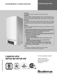
1
KN-2/4-CM2-808
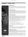
KN
Series
Cast iron condensing boilers
Models K N-2 and K N-4
Control manual
Control adjustment and
operation instructions
Also read and follow:
KN Boiler manual
KN Vent/air manual
This manual is intended only for use by a qualified heating installer/technician. Read and follow this manual, all supplements and related
instructional information provided with the boiler. Install, start and service the boiler only in the sequence and methods given in these
instructions. Failure to do so can result in severe personal injury, death or substantial property damage.
Do not use the boiler during construction. Construction dust and particulate, particularly drywall dust, will cause contamination of
the burner, resulting in possible severe personal injury, death or substantial property damage. The boiler can only be operated with a dustfree air supply. Follow the instruction manual procedures to duct air to the boiler air intake. If the boiler has been contaminated by operation
with contaminated air, follow the instruction manual guidelines to clean, repair or replace the boiler if necessary.
Affix these instructions near to the boiler/water heater. Instruct the building owner to retain the instructions for future use by a qualified
service technician, and to follow all guidelines in the User’s Information Manual.
P/N 42-9452 8/08 Copyright Hydrotherm
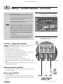
KN USER’S CONTROL MANUAL
The KN boiler — HeatNetTM control
Control overview
The KN HeatNet control monitors boiler temperature and limit circuit inputs, modulating boiler firing
rate to meet demand. The control uses microprocessor electronics, watching time-average response from
the system to anticipate how much heat the system needs. Coupled with the five-to-one turndown of the
KN boiler, this results in maximum possible condensing-mode operation. The KN boiler will provide
unmatched seasonal efficiency.
Indoor air reset (IAR)
HydroTherm’s unique approach to boiler output regulation is its Indoor Air Reset function. The control
monitors the demand from up to 8 different zones. Watching the demand duration and response to supply
temperature, averaging over time, the HeatNet control anticipates system needs. It sets boiler maximum
firing rate and adjusts supply water temperature to fine-tune boiler heat output. All that is required to
enable IAR is to connect thermostat circuit wires to the IAR inputs. The HeatNet control can also be
configured for outdoor reset operation, but IAR provides response based on system behavior rather than
just looking at outdoor temperature.
The HeatNet platform
HeatNet controls are designed to provide an integrated boiler management system on every boiler. The
platform provides multiple levels of selectivity. HeatNet electronics can be operated as a simple singleboiler control, while still providing intelligent regulation of boiler firing rate to match system demand.
With a few key strokes on the key pad, the HeatNet control can operate as a sophisticated multiple-boiler
controller, using simple RJ45 cable interfacing between units. The control can even accept external control
commands from building managements systems (Modbus standard, with optional bridge for BACnet or
LonWorks) or 20-milliamp analog input from an external controller.
The control method used by the HeatNet control is based on digital communications, which eliminates the
need for analog control signals. Analog signal inputs are supported, but a higher level of control precision,
repeatability and feedback is gained with digital communications.
The HeatNet control can be versatile, providing for operation in multiple ways:
• Operation as a stand-alone boiler.
• Operation as a boiler in a boiler network, using the on-board HeatNet protocol.
• Operation as a member boiler in a boiler management system.
• Operation as a member of a remotely-controlled boiler network (20-milliamp regulation).
• Setpoint can be determined by the HeatNet control or by a 20-milliamp input signal.
PID response
The HeatNet control uses proportional-integral-derivative calculations to determine the response to
boiler water temperature changes. This means it not only looks at how far away the water temperature is
from the setpoint temperature, but how fast the temperature is changing and how it has responded over
time. This ensures the boiler won’t make sudden unnecessary changes in firing rate.
Multiple boiler operation
HeatNet
Control panel
The HeatNet control easily interfaces with other HeatNet controls. Multiple boiler operation using HeatNet
protocol only requires RJ45 cables daisy-chained from boiler to boiler and a few key strokes setting up
control behavior. The master boiler is automatically selected by connecting a sensor lead to its HEADER
sensor terminals. The HeatNet control recognizes the sensor and configures the boiler as the master.
Other boilers only need to have an address assigned.
Among the advanced design features of the HeatNet control is the MOD-MAX setting. This limits the
firing rate of all boilers to a pre-set maximum (50% by default). This means all of the boilers will be run
at a very efficient level until all boilers are on. Only then can firing rate increase above this setting. Boiler
rotation can be first-on/first-off, first-on/last-off, or true rotation (the HeatNet control monitors the total
on time of all boilers, and rotates their usage so the total on time is the same for all).
2
P/N 42-9452 8/08 Copyright Hydrotherm
KN USER’S CONTROL MANUAL
The KN boiler — HeatNetTM control
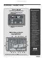
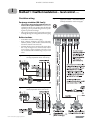
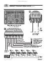
Wiring connections
1.
Power wiring, 120 vac
2.
Heat demand input
3.
DHW demand input
4.
Low fire terminals
5.
High fire terminals
6.
To boiler outlet water
temperature sensor
7.
To optional outdoor
temperature sensor
8.
To optional boiler return
water temperature sensor
9.
To optional header
temperature sensor
10.
To boiler postpurge pump
(factory piped and wired)
11.
To boiler circulator
12.
Alarm output dry contacts
13.
To external high limit and/or
low water cutoff if desired
14.
To flow switch, when used
15.
Used to activate combustion
air damper if desired
16.
To combustion air damper proving
switch, required when controlling
combustion air damper
17.
Indoor air reset inputs — connect
to up to 8 zone thermostats
18.
Optional 20 ma control signal input
19.
Remote enable to start when
operating on 20 ma input
20.
Optional HeatNet
communications board
21.
Boiler wiring socket to blower
and gas valve
22.
Boiler wiring socket to pressure
switches and Fenwal control
23.
Boiler wiring socket to
control panel
24.
Boiler wiring socket to
control panel
25.
Boiler wiring socket to
power switch
26.
Boiler wiring socket to transformer
27.
Termination DIP switches
components
P/N 42-9452 8/08 Copyright Hydrotherm
3
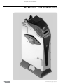
KN USER’S CONTROL MANUAL
The KN boiler — with HeatNetTM control
4
P/N 42-9452 8/08 Copyright Hydrotherm
KN USER’S CONTROL MANUAL
Contents
1 Method 1: HeatNet modulation – control. . . . . .page 6
•
The KN HeatNet control can control up to (16) KN boilers using built-in software and
hardware.
•
Install a RS485 interface on each boiler and connect with RJ45 HeatNet cables
(or shielded wires).
•
The header water temperature setpoint can be set by the master boiler or by a 4-20ma
input from an external controller.
•
Member boilers can override master boiler control if they receive a contact closure on
the Heat Demand or DHW Demand terminals.
2 Method 2: HeatNet modulation – BMS . . . . . page 14
•
This method uses the KN control’s built-in communications capabilities to accept
Modbus protocol inputs from a building management system. The master boiler control sequences and modulates the boiler network to accomplish the demands from the
building management system.
•
Each boiler requires the RS485 interface board and cable, above.
•
Boiler setup is essentially the same as for method 1, with the exception that each boiler
must be assigned both a HeatNet network address and an address for the Modbus interface.
•
An additional bus is required to interface with systems using BACnet or LonWorks protocol.
•
The master boiler will take control and regulate the boiler network if signal from the
BMS is lost or times out.
3 Method 3: External 4-20ma control . . . . . .page 16
•
Up to 5 boilers can be controlled by an external control that provides a 4-20ma input
signal. The external controls must also activate each boiler by closing a contact across
the boiler’s 4-20ma Remote Enable contacts.
•
Member boilers can override external boiler control if they receive a contact closure on
the Heat Demand or DHW Demand terminals.
4 Control menus and adjustments . . . . . . . . .page 22
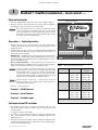
HeatNet
Control panel
•
Operating parameters and control behaviors are set using the KN control’s display/
keypad interface.
•
Refer to this section for the menu structure and explanations of the setting options.
5 Troubleshooting . . . . . . . . . . . . . . . . . . . . . . . .page 31
P/N 42-9452 8/08 Copyright Hydrotherm
5
KN USER’S CONTROL MANUAL
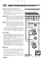
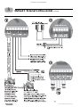
1
Method 1: HeatNet modulation – local control
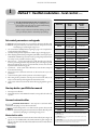
Figure 1
Electrical connection board (see item 10,
page 3 for location — Also see the wiring
summary illustrations on the next pages)
Figure 2
120VAC power service terminals on electrical
connection board — See Figure 15 for location
of the power terminal strip
Electrical shock hazard — Disconnect all electrical power
sources to the boiler before making any electrical connections.
Label all wires prior to disconnection when servicing controls.
Wiring errors can cause improper and dangerous operation!
Verify proper operation after servicing.
Failure to comply with the above could result in severe personal
injury, death or substantial property damage.
The electrical connections to this boiler must be made in
accordance with all applicable local codes and the latest
revision of the National Electrical Code, ANSI /NFPA-70.
Installation should also conform to CSA C22.1 Canadian
Electrical Code Part I if installed in Canada. Install a separate
120 volt 15 amp circuit for the boiler. A properly rated shutoff switch should be located at the boiler. The boiler must be
grounded in accordance with the authority having jurisdiction,
or if none, the latest revision of the National Electrical Code,
ANSI/NFPA-70.
Line voltage field wiring of any controls or other devices must
use copper conductors with a minimum size of #14 awg. Use
appropriate wiring materials for units installed outdoors.
Overview — control setup sequence
Follow the Boiler manual — Install the boilers according to the KN
Boiler manual before attempting to set up the control system.
1.
2.
3.
4.
5.
6.
7.
8.
9.
10.
Install all boilers per the Boiler manual.
Close the external gas valve on every boiler.
Wire all boilers following the guidelines in this section.
Attach a header sensor to the master boiler ONLY. The KN-2 control automatically configures the boiler with a header sensor as the master.
Set the master boiler control parameters using its display/keypad.
Set the master boiler’s termination DIP switches.
Set the termination DIP switches on the member boilers.
Set the member boilers’ control parameters using their display/keypads.
Follow the instructions in the Boiler manual to start up each boiler before proceeding
further.
Finish by connecting cables between the communications boards of all of the boilers
and verifying network operation.
Add communications modules
1. Insert a RS485 communications module onto each of the boilers’ electrical connection
panels, as shown in Figure 1.
Power supply (120 VAC)
1. See Figure 1 and Figure 2.
2. Connect minimum 14awg copper wire to the power connection as shown in Figure 2.
3. Install a fused service switch, mounted and installed in accordance with all applicable codes.
6
P/N 42-9452 8/08 Copyright Hydrotherm
KN USER’S CONTROL MANUAL
1
Method 1: HeatNet modulation – local control (cont.)
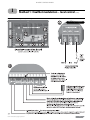
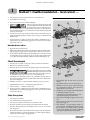
Circulator wiring
Postpurge circulator (KN-2 only)
•
•
Figure 5
Circulator wiring terminal strip (see Figure 1,
page 6, for location) — Also see the wiring
summary illustrations on the next pages)
The circulator shipped installed with the boiler cannot be used for system circulation. It must be used as
supplied from the factory. It circulates water after the boiler
stops firing to prevent potential damage from heat pocketing in the top of the heat exchanger.
The postpurge circulator is factory-piped and pre-wired. Do
not change the usage, the wiring, the location or the piping.
Boiler circulator
•
•
•
See the Boiler manual for circulator piping.
Figure 3, Figure 4, and Figure 5 show wiring of the Boiler
circulator (or boiler/system circulator) to the terminal strip
of the KN-2 electrical connection board.
DO NOT directly connect a circulator with a motor larger
than 1/4 hp. For larger motors, install a circulator relay or
motor contactor . Figure 3 and Figure 4 show the correct
ways to install the boiler circulator using a relay or motor
starter.
Figure 3
Wiring the boiler circulator using a circulator relay (required for motors over 1/4 hp)
Figure 4
Wiring the boiler circulator using a relay or
starter (required for motors over 1/4 hp)
P/N 42-9452 8/08 Copyright Hydrotherm
(KN-2 only)
7
KN USER’S CONTROL MANUAL
1
Method 1: HeatNet modulation – local control (cont.)
IAR (Indoor Air Reset) wiring, when used
•
Heat Demand terminal connections — The end switch leads from the zone valves
must connect to the Heat Demand terminals on the electrical connection board as
shown in Figure 7, page 9.
•
See Figure 6 for typical wiring to the IAR inputs when using 4-wire zone valves
without a zone controller. For other applications, such as circulator relays or zone
controllers, see Appendix A in the Boiler manual..
Figure 6
Indoor Air Reset wiring to IAR terminals with
4-wire zone valves and no zone controller
(see Figure 7, page 9 for terminal block 6 location)
Polarity — The connections to the IAR positive terminals (IAR +)
must be to the same location on the zone valve as the thermostat wire,
as shown in Figure A1. The connections to the IAR negative terminals
(IAR –) must be from the zone valve terminal connected to the 24VAC
common line, as shown. Connecting the wires incorrectly can cause the
transformer to be shorted out and damaged. Verify the wiring with a
voltmeter.
Always use a voltmeter to check the leads coming from the end switches
of the zone valves. With the thermostat calling for heat, connect the
voltmeter leads across the wires coming from the end switches. If
the meter shows a voltage reading, the zone valve wires are incorrect.
Change the wiring and retest. DO NOT connect the wires to the boiler
until you have tested as described. Incorrect wiring can damage the
boiler control or other system components.
•
If there is only one transformer feeding all of the zone valves in the system, you can
omit the wires to the IAR negative terminals (IAR –) on all but one of the zone
valves. This is because these terminals are jumpered internally on the electrical
connection board. If there is more than one transformer, provide one wire from
each transformer common side to one of the IAR negative terminals (IAR –).
Sensor wiring
•
Header sensor is required — A header sensor must be installed in the system
supply piping. Connect the header sensor ONLY to the master boiler. Install
the header sensor in an immersion well. Locate the sensor where it will accurately
sense the system water supply temperature. Connect the sensor leads to the electrical connection board as shown in Figure 8, page 10.
•
Outdoor reset application — To operate with outdoor reset, purchase and install an outdoor sensor. Mount the sensor such that it is shielded from direct sunlight if possible and not likely to be covered by snow drifts or debris. Connect the
outdoor sensor leads to the master boiler’s electrical connection board as shown
in Figure 8, page 10. (Member boilers could have their own outdoor sensor if they
will be operated in override mode by closing the Heat Demand terminals.)
•
Return water temperature sensor — The return water temperature sensor
is optional, only needed if you want to automatically control the boiler postpurge
pump cycle time. Install the sensor in a well in the boiler return piping. Connect
the sensor leads to the electrical connection board as shown in Figure 8, page 10.
DHW wiring
•
To operate the boiler for domestic water heating with a storage tank, install and pipe
the tank according to the tank manufacturer’s instructions and the recommended
piping diagrams in this manual. Consult the factory for applications not covered.
•
The circulator used for DHW must be operated by a circulator relay or zone controller that is activated when the tank aquastat calls for heat.
•
Connect the tank aquastat terminals across the DHW DEMAND terminals on the
master boiler’s electrical connection board as shown in Figure 7, page 9. (Member
boilers could be connected to tank aquastats if they are piped appropriately and
intended to operate in override mode.)
8
P/N 42-9452 8/08 Copyright Hydrotherm
KN USER’S CONTROL MANUAL
1
Figure 7
Method 1: HeatNet modulation – local control (cont.)
KN wiring summary — wiring to electrical connection board
Also see Figure 2, page 6.
P/N 42-9452 8/08 Copyright Hydrotherm
9
KN USER’S CONTROL MANUAL
1
Figure 8
Method 1: HeatNet modulation – local control (cont.)
KN wiring summary — wiring to electrical connection board, continued (see Figure 7, page 9, for terminal strip locations)
Also see Figure 5, page 7.
(KN-2 only)
10
P/N 42-9452 8/08 Copyright Hydrotherm
KN USER’S CONTROL MANUAL
1
Method 1: HeatNet modulation – local control (cont.)
External interlocks
Figure 9
Termination DIP switches (see item 7, Figure 7,
page 9 for location)
1. Wire external limits and flow switch, when used, as shown in Figure 8, page 10.
2. If wiring to and from a motorized combustion air damper, follow the guidelines
given in Figure 8, page 10. Connect only to the master boiler.
If any of the member boilers is to operate in override mode, and the
system is equipped with a combustion air damper, you must provide
special wiring in order to ensure the damper opens and proves when
the boiler fires. This must be done without compromising the wiring
between the master boiler and the damper.
Overrides — Control priorities
3. The KN control can provide override operation for any or all member boilers in
a HeatNet network. This requires the boilers be piped with appropriate isolation
piping and controls.
4. Override is done by closing a contact across the Heat Demand or DHW Demand
terminals of any boiler. These priority inputs override all network controls or 420mA input controls to the boiler.
5. DHW Demand — The DHW Demand closure takes priority for ALL boilers, including the master and all members. When DHW Demand closes, the boiler or
boilers immediately switch to DHW operation, including setting the water temperature to the DHW Setpoint.
6. Space heating, Heat Demand — If any member boiler sees closure across its
Heat Demand terminals it will begin operation in space heating mode independently of commands from the master boiler or 4-20mA input source.
Table 1
Termination DIP switch settings
Do not wire boilers for override operation unless the piping design
provides automatic isolation of the overriding boilers. The master
boiler would be unable to properly control system water temperature
if member boilers were to input heat to the system without control
from the master. DHW operation, in particular, would raise the supply
temperature from overriding boilers to the DHW Setpoint.
Master
Override operation control setup — Boilers must be set up with
operating parameters necessary during their override operation; i.e.,
local setpoint, DHW setpoint, etc.
Switch 1:
Switch 2:
Switch 3:
Switch 4:
ON
ON
OFF
OFF
Switch 1:
Switch 2:
Switch 3:
Switch 4:
ON
ON
ON
ON
Last member
Switch 1:
Switch 2:
Switch 3:
Switch 4:
ON
ON
OFF
OFF
Switch 1:
Switch 2:
Switch 3:
Switch 4:
ON
ON
OFF
OFF
Other members
Switch 1:
Switch 2:
Switch 3:
Switch 4:
OFF
OFF
OFF
OFF
Switch 1:
Switch 2:
Switch 3:
Switch 4:
OFF
OFF
OFF
OFF
Boiler
Priority 2 = Heat Demand
Priority 3 = HeatNet input
Modbus
(see note)
7. Summary — priority sequence is:
Priority 1 = DHW Demand
HeatNet
Note: Modbus setup is for applications controlled by a building management system. For
systems using BACnet or LonWorks, a bridge board is used to interface with the KN-2
control. The switch is “on” when in the down position and “off ” when in the up position.
Set termination DIP switches
1. The HeatNet network needs to recognize the beginning and end of the
network. This requires setting the four DIP switches on each boiler’s electrical
connection board.
2. See Figure 9 for location of the switches.
3. See Table 1 for required settings. The table gives settings for HeatNet modulation — local control and for remote control from a building management system
(Modbus protocol).
4. DO NOT connect the communications cables (or shielded wires) between boilers
until all boilers have had parameters set and then been started up following all instructions in the KN Boiler manual.
P/N 42-9452 8/08 Copyright Hydrotherm
11
KN USER’S CONTROL MANUAL
1
Method 1: HeatNet modulation – local control (cont.)
Table 2
Control parameters
Close the external manual gas valve on every boiler before
proceeding. DO NOT open any gas valve, or attempt to fire any
boiler, until the boilers have been set up and verified following
the instructions in the KN Boiler manual.
Parameter
Failure to comply could cause a boiler failure, leading to possible
severe personal injury, death or substantial property damage.
HEAT BAND
Set control parameters on keypads
Before turning boilers on to set parameters, disconnect all call for heat
wiring at the electrical connection boards. This will prevent the boiler
for attempting to cycle during the setup process.
1. See “Control menus and adjustments,” beginning on page 22 for a complete list of
control parameters and explanations.
2. Carefully read the parameter explanations in Table 8, page 25 through page 29.
3. When adjusting the limit band, operating limit (OP LIMIT), local setpoint (LOC
SETPOINT) and DHW setpoint, make sure the operating temperature bands do
not overlap or cause potential for nuisance cycling.
4. Indoor air reset — Use this option whenever possible. The indoor air technology
monitors space heating demand to help the boiler operate at the highest possible
efficiency throughout the season. To operate with IAR, you must wire to the IAR
input terminals as described on page 18.
5. System clock — Set the system clock on all boilers to ensure the time stamps will
be accurate in the data logs.
6. Turn on the power to each boiler and set the on/off switch to ON as you set its
parameters.
7. Use the boiler’s keypad to enter the parameters as described on page 22.
8. After setting a boiler’s parameters, turn the power off to the boiler until you are
ready to start the boiler up following the Boiler manual instructions.
9. Set the master boiler and each member boiler, following the guidelines given in
Table 2.
Start up boilers per KN Boiler manual
1. Turn off power to all boilers.
2. Follow all instructions in the KN Boiler manual to start up each boiler and verify
operation.
Connect network cables
Electrical shock hazard — Turn off power to each boiler before
attempting to connect the network cables.
Before turning boilers on to check network operation, disconnect all
call for heat wiring at the electrical connection boards. This will prevent
the boiler for attempting to cycle during the setup process.
Master boiler cable
1. Connect an RJ45 cable to the master boiler H-Link OUT block (item 2, Figure 10,
page 13) or 3-wire shielded cable to the H-Link terminal strip (item 4, Figure 10,
page 13). The other end of this cable will be attached to the first member boiler in
following steps.
12
Master
boiler
Member
boiler
(see notes)
Set on master boiler only
LOC SETPOI NT
Set
HD only1
SOURCE
Set
HD or DHW only1,2
DHW SETPOINT
Set if DHW will
be used
DHW only2
OP LIMIT
Set
Set
LIMIT BAND
Set
Set
IA RESET
ON if IAR is used,
or set to OFF
Do not set
OA SHUTDOWN
Set ON if used
or set to OFF
HDOA only3
OA SETPOINT
Set if used
HDOA only3
OA RESET
Set if used
HDOA only3
OA SETPTS
Set if used
HDOA only3
DELTA ENABLE
Set if used
Set if used
DELTA TEMP
Set if used
Set if used
PURGE TIME
Set if used
Set if used
ALWAYS ON
Set if used
Set if used
MASTER PUMP
Set if used
Do not set
NIGHT SETBACK
OPTIONS (all)
AUX FUNCTIONS
Set on master boiler only
Set
Set
Set on master boiler only
SYSTEM CLOCK
Set
Set
LOCAL ADD
Automatic
Set (beginning at 2)
CONSOLE ADD
Automatic
Set (beginning at 2)
MODULAR BOILER
Set on master boiler only
MODULATION PID
Set on master boiler only
FIRING MODE
Set on master boiler only
SENSOR #
Set
HD/HDOA only1,3
TYPE
Set
HD/HDOA only1,3
CALIBRATE ?
On any boiler if required
PASSWORD
Set
Set
COMMUNICATIONS
Set
Set
LOAD DEFAULTS
On any boiler if required
SYSTEM
On any boiler if required
Notes:
1 — HD Only means to set the parameter for a member boiler only if it is wired for
Heat Demand override.
2 — DHW Only means to set the parameter for a member boiler only if it is wired
for DHW Demand override.
3 — HDOA Only means to set these parameters only if the member boiler will be
operated with outdoor reset when put in override mode with closure across its Heat
Demand terminals (requires outdoor sensor connected to boiler).
P/N 42-9452 8/08 Copyright Hydrotherm
KN USER’S CONTROL MANUAL
1
Method 1: HeatNet modulation – local control (cont.)
2. Turn on power to the master boiler and set its on/off switch to ON.
3. You should hear at least 2 beeps.
4. The control’s firmware version number will display.
5.
After the control’s timer finishes, the display will
show STANDBY and SYS SET. This verifies that
the master boiler is setup correctly as the master.
The same display will show on member boilers when there is a call for heat from
the master boiler. When there is no call for heat at a member boiler, the display will
show LOC SET instead.
6. If the master is functioning correctly, the yellow LED’s on the H-Link jack ports
will blink. The blinking indicates that the master is trying to communicate with
member boilers.
7. If a FAULT message is displayed, clear the faults until the STANDBY message is
displayed. Refer to troubleshooting suggestions at the end of this manual if you
cannot resolve the issue.
Figure 10
RS485 communications board
Member boiler cables
1. Begin with the first member boiler.
2. Plug the other end of the master boiler’s communications cable to the member boiler’s
input port (Figure 10, page 13, item 2 for RJ45 cable or item 4 for 3-wire cable).
3. Connect cables to all of the member boilers by cabling from one to the next. Connect
incoming cables to item 1 or 4, Figure 10, page 13. Connect outgoing cables to item
2 or 4. (Note that shielded cable wires will share terminals when using item 4.)
Check the network
1. Turn the power on and the on/off switch to ON for all of the member boilers.
2. Allow time for each boiler to initialize.
3. After about 30 seconds, the master boiler should recognize the member boilers.
4.
Navigate to the BOILERS menu, then to HEAT
NET BOILERS display. The master control will
show the boilers it recognizes. Values from 10 to
15 will display as letters (10=A, 11=B, 12=C, 13=D, 14=E and 15=F).
5. If the display shows a blank space, such as “123_56789ABC,” the control does not
detect the missing boiler (boiler 4). Check the yellow LED on the communication
port of the missing boiler.
6. NORMAL connection — LED should flash steadily, about twice per second.
7. TERMINATION incorrect — LED will flash rapidly and stay on.
8. OPEN connection — LED does not flash at all.
9. If a FAULT message is displayed, clear the faults until the STANDBY message is
displayed. Refer to troubleshooting suggestions at the end of this manual if you
cannot resolve the issue.
Start the system
1.
2.
3.
4.
5.
Turn off power to all boilers.
Connect all call for heat wiring to the boilers.
Turn on power to all boilers and turn the on/off switches to ON.
The boilers should now operate normally, as described in the Boiler manual.
The master boiler will sequence and modulate boilers as necessary to control the
water temperature.
6. The master boiler will show the number of boilers firing as well as the temperature
and heat band display. Use the UP/DOWN keys to scroll through the displays to
watch the process of starting and stopping boilers.
P/N 42-9452 8/08 Copyright Hydrotherm
1. RJ45 HeatNet cable IN from master or previous
member
2. RJ45 HeatNet cable OUT to next member boiler
3. Shielded wire (3-2ire), option to RJ45 cable, HeatNet communications INPUT and connection for
additional boilers on the network
4. Shielded wire (option to RJ45 cable) Modbus INPUT
from building management system
5. USB cable port (for USB cable connection to a PC —
required when updating control firmware)
6. RJ45 cable from building management system, when
used
7. Plug for insertion into KN control electrical connection panel (see page 3)
8. NOT SHOWN — An optional plug-in bridge is required to interface with building management systems
that use BACnet or LonWorks protocol. The KN
control supports Modbus protocol with no additional
components except the RS485 interface board.
13
KN USER’S CONTROL MANUAL
2
Method 2: HeatNet modulation – BMS control
Overview
Modbus holding (read/write) registers
Address
1. This method uses an RS485 digital communications cable
with the Modbus protocol to control a boiler or HeatNet network.
Table 3
Data
Type
40001
Unsigned
Boiler/System Enable/Disable
40002
40003
40004
Unsigned
Unsigned
Unsigned
System Setpoint Timer (1)
System Setpoint (1)
Outdoor Air Reset Enable/Disable
40005
40006
Unsigned
Unsigned
Outdoor Air Setpoint
Water Temperature at High Outside Air
6. The master boiler assumes the role of MEMBER, RTU, 192Kb,
8 bits, Even Parity, 1 stop bit, when connected to a BMS.
40007
40008
40009
40010
40011
40012
40013
40014
40015
40016
Unsigned
Unsigned
Signed
Unsigned
Unsigned
Unsigned
Unsigned
Unsigned
Unsigned
Unsigned
High Outside Air Temperature
Water Temperature at Low Outside Air
Low Outside Air Temperature
Set Clock – Month (2)
Set Clock – Day of Month (2)
Set Clock – Year (2)
Set Clock – Hours (2)
Set Clock – Minutes (2)
Set Clock – Seconds (2)
Set Clock – Day of Week (2)
7. The Member Boilers should not be connected to a BMS
system other than to view read-only addresses.
40017
Unsigned
Set Clock – After the Set Clock Registers listed
above have been written, a 1 must be written to
this location to set the clock. (2)
2. The boiler or boiler network will operate as in the HeatNet local control method (Section 1 of this manual). But, instead of
the HEAT DEMAND input, a software form of the HEAT
DEMAND input is used (address 40001 — Boiler/System
Enable/Disable).
3. The System Setpoint Timer needs to be loaded periodically
to allow the HeatNet system to revert to local control from
the master boiler in the event communications is lost.
4. The Modbus protocol allows writing and reading registers
using Modbus commands. An optional BACnet or LonWorks
bridge module can be used to connect the Modbus network to a BACnet or LonWorks network.
5. This method allows enabling and disabling the boiler or
HeatNet system; changing setpoints; and reading boiler
status or temperatures remotely, using digital commands
from a Building Management System.
Description
Valid Values/
Range
0 = Disabled/Off
1 = Enabled/On
0 – 65535 seconds
40°F – 220 °F
0 = Disabled/Off
1 = Enabled/On
40°F -100 °F
60°F -150 °F
50°F -90 °F
70°F -220 °F
-35°F -40 °F
0 – 11
1 – 31
0 – 99
0 – 23
0 – 59
0 – 59
1 – Monday 7
– Sunday
1
MODBUS registers
1. See Table 3, page 14; Table 4, page 14; and Table 5, page 15
for register requirements.
2. The system setpoint timer and system setpoint work in tandem to externally control the operating setpoint.
3. The setpoint (countdown) timer should be loaded with a
timeout value (in seconds) prior to writing the system setpoint.
4. When the timer reaches zero, the control assumes that the
BMS is no longer operating and the local setpoint (saved on
the master control) is reloaded.
5. This is a fail-safe feature used to help safeguard the system in
case of BMS failure.
6. If the setpoint timer is not written, a default timeout value of
60 seconds is assumed.
7. To write the system clock, registers 40009 – 40015 must
first be loaded with the correct date and time. Then, a 1
must be written to register 16 to write the date and time to
the system clock.
14
Table 4
Bit
0
1
2
3
4
5
6
7
8
9
10
11
12
13
14
15
Boiler status flags
Description
Disabled
Local Override
Alarm
Failed
Member Error
Boiler Running
Pump Running
Spare 3 Interlock
LWCO Interlock
VFD Interlock
Gas Prove
Spare 4
Operator Interlock
Water Prove (Flow) Interlock
Air Prove UV Sensor Interlock
Main Valve
Bit
16
17
18
19
20
21
22
23
24
25
26
27
28
29
30
31
Description
Pilot Valve
Blower
Ignition Alarm
Valve Alarm
High Limit
Air Prove Switch
XS Factory
Software Operator
Header Sensor not Present
Supply Sensor not Present
Return Sensor not Present
Outside Air Sensor not Present
——
——
Master Boiler
Present (Boiler Detected)
P/N 42-9452 8/08 Copyright Hydrotherm
KN USER’S CONTROL MANUAL
2
Method 2: HeatNet modulation – BMS control (cont.)
BACnet or LonWorks protocols
Modbus input (read-only) registers
Address
1. Install the correct bridge to adapt to building management
systems using BACnet or LonWorks protocols.
Table 5
Data
Type
30001
Unsigned
Boilers Running
0 – 16
30002
Unsigned
Modulation (% BTU Load)
0 – 100
30003
Signed
Header / System Temperature
32 – 250 °F
30004
Signed
Supply Temperature
32 – 250 °F
1. Wire and set up the master boiler and member boilers exactly
as for HeatNet modulation — local control applications.
See page 6 through page 13.
30005
Signed
Return Temperature
32 – 250 °F
30006
Signed
Outside Air Temperature
-40 – 250 °F
2. ALL control parameters must be set up just as for the local
control method.
30007
Signed
Spare Input 1
-32768 to 32767
30008
Signed
Spare Input 2
-32768 to 32767
3. The ONLY difference in setup is the termination DIP switch
settings. Use the settings for Modbus communications given
in Table 1, page 11.
30009
Unsigned
Clock – Month
0 – 11
30010
Unsigned
Clock – Day
1 – 31
4. Connect communications cables (RJ45 or shield-wire
cables) between the control communications boards as for
the local control method.
30011
Unsigned
Clock – Year
0 – 99
30012
Unsigned
Clock – Hours
0 – 23
30013
Unsigned
Clock – Minutes
0 – 59
30014
Unsigned
Clock – Seconds
0 – 59
30015
Unsigned
Clock – Day of Week
30016 –
30047
Unsigned
Boilers 1 – 16 status flag (32-bit) registers. The
upper 16-bits of each 32-bit register is stored at
odd numbered addresses 30016 –30046. The
lower 16-bits of each 32-bit register is stored at
even numbered addresses 30017 – 30047.
See the Boiler
Status Flags
Table Below
30048 –
30079
Unsigned
Boilers 1 – 16 runtime (32-bit) registers. The
upper 16-bits of each 32-bit register is stored at
odd numbered addresses 30048 – 30078. The
lower 16-bits of each 32-bit register is stored at
even numbered addresses 30049 – 30079.
When the upper and lower registers are combined
they form a 32-bit unsigned integer that is the
number of seconds that the boiler has been
running. For instance: (((Register 29) * 65536)
+ Register 30) = Boiler 1 runtime in seconds.
Boiler 1 is the master boiler. Boilers 2 – 16 are
member boilers.
0 – 4294967295
seconds
2. The bridge translates the BACnet or LonWorks input to
the Modbus protocol for compatibility with the HeatNet
controls.
Wiring and set-up
5. Verify network operation BEFORE connecting the building
management system.
Connect the BMS cable
1. DO NOT connect the building management system cable
until the boiler network has been proven to operate independently. The system is designed to revert to local control
by the master boiler should communications with the
building management system be lost.
2. Turn off power to the master boiler.
3. See Figure 10, page 13. Connect an RJ45 cable to the BMS
input port, item 6. Or use shielded wire cable, connected to
terminal block, item 3.
Verify BMS/HeatNet operation
1. Turn on power to the master boiler.
2. Allow the master boiler to initialize.
Description
Valid Values/
Range
1 – Monday 7 –
Sunday
3. Verify operation with the building management system.
P/N 42-9452 8/08 Copyright Hydrotherm
15
KN USER’S CONTROL MANUAL
3
Method 3: External 4-20ma control
Figure 11
Electrical connection board (see item 10,
page 3 for location — Also see the wiring
summary illustrations on the next pages)
Figure 12
120VAC power service terminals on electrical
connection board — See Figure 15 for location of the power terminal strip
Electrical shock hazard — Disconnect all electrical power
sources to the boiler before making any electrical connections.
Label all wires prior to disconnection when servicing controls.
Wiring errors can cause improper and dangerous operation!
Verify proper operation after servicing.
Failure to comply with the above could result in severe personal
injury, death or substantial property damage.
The electrical connections to this boiler must be made in
accordance with all applicable local codes and the latest
revision of the National Electrical Code, ANSI /NFPA-70.
Installation should also conform to CSA C22.1 Canadian
Electrical Code Part I if installed in Canada. Install a separate
120 volt 15 amp circuit for the boiler. A properly rated shutoff switch should be located at the boiler. The boiler must be
grounded in accordance with the authority having jurisdiction,
or if none, the latest revision of the National Electrical Code,
ANSI/NFPA-70.
Line voltage field wiring of any controls or other devices must
use copper conductors with a minimum size of #14 awg. Use
appropriate wiring materials for units installed outdoors.
Overview — control setup sequence
Follow the Boiler manual — Install the boilers according to the KN
Boiler manual before attempting to set up the control system.
1.
2.
3.
4.
5.
6.
This method can be used for from 1 to 5 boilers.
Install all boilers per the Boiler manual.
Close the external gas valve on every boiler.
Wire all boilers following the guidelines in this section.
DO NOT install a header sensor on any of the boilers.
Disconnect the wires to the boilers’ Remote Enable terminals (and any override
wiring to Heat Demand or DHW Demand terminals) to ensure there will be no
call for heat while proceeding.
7. Set the boilers’ control parameters using their display/keypads.
8. Follow the instructions in the Boiler manual to start up each boiler before proceeding further.
9. Finish by reconnecting call for heat wiring, then operating the complete system to
verify operation in all modes.
Connect 4-20mA wiring
1. See Figure 16, page 19 for wiring from the 4-20mA controller. The control must
provide the 4-20mA signal and a contact for each boiler to enable its operation by
closing across the Remote Enable contact.
Power supply (120 VAC)
1. See Figure 11 and Figure 12.
2. Connect minimum 14awg copper wire to the power connection as shown in Figure 12.
3. Install a fused service switch, mounted and installed in accordance with all applicable codes.
16
P/N 42-9452 8/08 Copyright Hydrotherm
KN USER’S CONTROL MANUAL
3
Method 3: External 4-20ma control (continued)
Circulator wiring
Postpurge circulator (KN-2 only)
•
•
Figure 15
Circulator wiring terminal strip (see Figure 11,
page 16, for location) — Also see the wiring summary illustrations on the next pages)
The circulator shipped installed with the boiler cannot be used for system circulation. It must be used as
supplied from the factory. It circulates water after the boiler
stops firing to prevent potential damage from heat pocketing
in the top of the heat exchanger.
The postpurge circulator is factory-piped and pre-wired. Do
not change the usage, the wiring, the location or the piping.
Boiler circulator
•
•
•
See the Boiler manual for circulator piping.
Figure 13, Figure 14, and Figure 15 show wiring of the Boiler
circulator (or boiler/system circulator) to the terminal strip
of the KN-2 electrical connection board.
DO NOT directly connect a circulator with a motor larger
than 1/4 hp. For larger motors, install a circulator relay or
motor contactor . Figure 13 and Figure 14 show the correct
ways to install the boiler circulator using a relay or motor
starter.
Figure 13
Wiring the boiler circulator using a circulator
relay (required for motors over 1/4 hp)
Figure 14
Wiring the boiler circulator using a relay or
starter (required for motors over 1/4 hp)
P/N 42-9452 8/08 Copyright Hydrotherm
(KN-2 only)
17
KN USER’S CONTROL MANUAL
3
Method 3: External 4-20ma control (continued)
4-20mA operation
•
To operate the boiler for domestic water heating with a
storage tank, install and pipe the tank according to the tank
manufacturer’s instructions and the recommended piping
diagrams in this manual. Consult the factory for applications not covered.
•
The circulator used for DHW must be operated by a circulator relay or zone controller that is activated when the tank
aquastat calls for heat.
•
Connect the tank aquastat terminals across the DHW
DEMAND terminals on the master boiler’s electrical connection board as shown in Figure 7, page 9. (Member
boilers could be connected to tank aquastats if they are
piped appropriately and intended to operate in override
mode.)External interlocks
1. A 4.02 mA current signal will start the boiler, at low fire. A
20mA signal will cause the boiler to go to full input.
2. Between these input signal limits, the boiler modulates. The
boiler firing rate percentage is equal to the percentage of the
signal between 0 and 20 mA. Example, a signal of 12 mA is
60% of 20 mA, so the boiler firing rate would be 60% of max.
3. In addition to the 4-20mA signal, the remote controller
must also close a contact across each boiler’s Remote Enable contact in order for the boiler to fire.
4. See Figure 16, page 19 for wiring. Notice that the boiler 420mA terminals are wired in series.
IAR (Indoor Air Reset) wiring —
apply ONLY if using space heating
override mode
•
•
IAR can only be used if one or more of the boilers is wired
and piped for override operation. Override would occur
when a contact closed across the Heat Demand terminals.
While this contact is closed, the boiler will operate based on
local control, including feedback for IAR if wired.
If override operation will be used, and you want to operate
with IAR when in override mode, follow the instructions
under Method 1 in this manual to wire for IAR.
Sensor wiring
•
Header sensor cannot be used when the boilers
are configured for remote operation by a 24-mA
source.
•
Outdoor reset application can be done only in override mode — To operate with outdoor reset, purchase and
install an outdoor sensor. Mount the sensor such that it is
shielded from direct sunlight if possible and not likely to be
covered by snow drifts or debris. Connect the outdoor sensor leads to the master boiler’s electrical connection board
as shown in Figure 8, page 10. (Member boilers could have
their own outdoor sensor if they will be operated in override mode by closing the Heat Demand terminals.)
•
Return water temperature sensor — The return water temperature sensor is optional, only needed if you want
to automatically control the boiler postpurge pump cycle
time. Install the sensor in a well in the boiler return piping.
Connect the sensor leads to the electrical connection board
as shown in Figure 8, page 10. Each boiler requires a return
water temperature sensor.
5. Wire external limits and flow switch, when used, as shown
in Figure 17, page 20.
6. The combustion air interlocks cannot be used when operating with a 24-mA remote control. Combustion air damper
control must be done by the remote control system.
Overrides — Control priorities
1. The KN control can provide override operation for any or
all member boilers. This requires the boilers be piped with
appropriate isolation piping and controls.
2. Override is done by closing a contact across the Heat Demand or DHW Demand terminals of any boiler. These
priority inputs override all 4-20mA input controls to the
boiler.
3. DHW Demand — The DHW Demand closure takes priority for ALL boilers, including the master and all members.
When DHW Demand closes, the boiler or boilers immediately switch to DHW operation, including setting the water
temperature to the DHW Setpoint.
4. Space heating, Heat Demand — If any member boiler
sees closure across its Heat Demand terminals it will begin
operation in space heating mode independently of commands from the 4-20mA input source.
Do not wire boilers for override operation unless
the piping design provides automatic isolation of
the overriding boilers.
Override operation control setup — Boilers
must be set up with operating parameters
necessary during their override operation; i.e.,
local setpoint, DHW setpoint, etc.
5. Summary — priority sequence is:
DHW wiring — ONLY if using DHW
override mode
Priority 1 = DHW Demand
•
Priority 2 = Heat Demand
The boiler (or boilers) must be piped with isolation
valves and wired for override operation. Override of
the 4-20mA input will occur if a contact closes across the
boiler’s DHW Demand terminals.
18
Priority 3 = 4-20mA Input/Enable
P/N 42-9452 8/08 Copyright Hydrotherm
KN USER’S CONTROL MANUAL
3
Figure 16
Method 3: External 4-20ma control (continued)
KN wiring summary — wiring to electrical connection board
P/N 42-9452 8/08 Copyright Hydrotherm
19
KN USER’S CONTROL MANUAL
3
Figure 17
Method 3: External 4-20ma control (continued)
KN wiring summary — wiring to electrical connection board, continued (see Figure 7, page 9, for terminal strip locations)
(KN-2 only)
20
P/N 42-9452 8/08 Copyright Hydrotherm
KN USER’S CONTROL MANUAL
3
Method 3: External 4-20ma control (continued)
Table 6
Control parameters
Close the external manual gas valve on every boiler before
proceeding. DO NOT open any gas valve, or attempt to fire any
boiler, until the boilers have been set up and verified following
the instructions in the KN Boiler manual.
Parameter
HEAT BAND
Set
Failure to comply could cause a boiler failure, leading to possible
severe personal injury, death or substantial property damage.
LOC SETPOINT
HD only1
SOURCE
HD only1
DHW SETPOINT
DHW only2
OP LIMIT
Set
LIMIT BAND
Set
IA RESET
HD only1
OA SHUTDOWN
HD or HDOA only1,3
OA SETPOINT
HD or HDOA only1,3
OA RESET
HDOA only3
OA SETPTS
HDOA only3
DELTA ENABLE
Set if used
DELTA TEMP
Set if used
PURGE TIME
Set if used
ALWAYS ON
Set if used
MASTER PUMP
Set as required
NIGHT SETBACK
HD only1
OPTIONS (all)
Set
AUX FUNCTIONS
DO NOT use
SYSTEM CLOCK
Set
LOCAL ADD
DO NOT use
CONSOLE ADD
DO NOT use
MODULAR BOILER
DO NOT use
MODULATION PID
DO NOT use
FIRING MODE
DO NOT use
SENSOR #
HD/HDOA only1,3
TYPE
HD/HDOA only1,3
CALIBRATE ?
Only as required
PASSWORD
Set
COMMUNICATIONS
Only as required
LOAD DEFAULTS
Only as required
SYSTEM
Only as required
Set control parameters on keypads
Before turning boilers on to set parameters, disconnect all call for heat
wiring at the electrical connection boards, including the wiring to
the boilers’ Remote Enable terminals. This will prevent the boiler for
attempting to cycle during the setup process.
1. See “Control menus and adjustments,” beginning on page 22 for a complete list of
control parameters and explanations.
2. Carefully read the parameter explanations in Table 8, page 25 through page 29.
3. When adjusting the limit band, operating limit (OP LIMIT), local setpoint (LOC
SETPOINT) and DHW setpoint, make sure the operating temperature bands do
not overlap or cause potential for nuisance cycling.
4. System clock — Set the system clock on all boilers to ensure the time stamps will
be accurate in the data logs.
5. Turn on the power to each boiler and set the on/off switch to ON as you set its
parameters.
6. Use the boiler’s keypad to enter the parameters as described on page 22.
7. After setting a boiler’s parameters, turn the power off to the boiler until you are
ready to start the boiler up following the Boiler manual instructions.
Start up boilers per KN Boiler manual
(see notes)
1. Turn off power to all boilers.
2. Follow all instructions in the KN Boiler manual to start up each boiler and verify
operation.
Start the system
1. Turn off power to all boilers.
2. Connect all call for heat wiring to the boilers.
3. Turn on power to all boilers and turn the on/off switches to ON.
4. The boilers should now operate normally, as described in the Boiler manual.
5. The remote 4-20mA controller will sequence and modulate boilers as necessary to
control the water temperature.
P/N 42-9452 8/08 Copyright Hydrotherm
When to set
Notes:
1 — HD Only means to set the parameter for a member boiler only if it is wired for
Heat Demand override.
2 — DHW Only means to set the parameter for a member boiler only if it is wired
for DHW Demand override.
3 — HDOA Only means to set these parameters only if the member boiler will be
operated with outdoor reset when put in override mode with closure across its Heat
Demand terminals (requires outdoor sensor connected to boiler).
21
KN USER’S CONTROL MANUAL
4
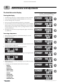
Control menus and adjustments
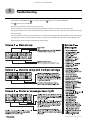
The Heat Net control display
Starting the display
Figure 18
Heat Net display during Standby (no call
for heat) — pressing the DOWN key on the
keypad changes the display as shown
1. Check all wiring to make sure it is complete and all wires are securely connected.
2. Verify that the HEAT DEMAND and DHW DEMAND wires are removed.
3. Close the external gas valve on every boiler.
4. Turn on power to the boiler and then turn the boiler on/off switch ON.
5. The control will beep at least twice and the display will show the first STANDBY
display in Figure 18. Note that pushing the DOWN button on the keypad will
change the right side of the display as shown, providing information on various
setpoints and parameters.
6. The display, LOC SET, means the setpoint temperature. Figure 18 shows the factory default values.
Accessing setup menus
1. With the display in STANDBY, press and hold the BACK key for 5 seconds.
2. The display will change to:
3. Press the SELECT key to select setup. (Note that pressing the DOWN key would
change the selection to VIEW LOG.)
4. The display will now show the first options in the setup menus:
5. Press the DOWN key to access additional menu options. Pressing the DOWN
button once will change the display to:
6. The cursor moves to the second line, indicating this option could now be selected
with the SELECT key.
7. Continuing to press the DOWN key will access these menu options:
•
BOILERS
•
SETPOINTS
•
INDOOR AIR
•
PUMP OPTIONS
•
NIGHT SETBACK
•
OPTIONS
•
LOG/RUNTIME
•
AUX FUNCTIONS
•
SYSTEM CLOCK
•
ADVANCED SETUP
22
P/N 42-9452 8/08 Copyright Hydrotherm
KN USER’S CONTROL MANUAL
4
Table 7
Control menus and adjustments (continued)
Setup menus (see Table 8, page 25 for explanations)
To enter Setup: From STANDBY, hold
for 5 seconds. Then press
with cursor on SETUP. Make sure there is no call for heat at
the boiler before attempting to perform setup adjustments.
until the display returns to standby, or turn boiler ON/OFF switch off, then on.
To return to STANDBY, press/release
Level 1
Level 2
next
Level 3
next item
next item
Level 4
Default {Range}
to change value
next item
item
to select
to select
to select
back one level
back one level
back one level
to accept value and return to
previous menu level
to select
KN-2 V X.X
BOILERS
SETPOINTS
INDOOR AIR
Shows firmware version number
KN-2
1 {1 to 16} — display only
# BOILERS
1
LEAD BOILER
LEAD BOILER
1
HEAT BAND
1 — display only — the lead boiler is the boiler with
a HEADER sensor connected
30 °F {10 to 50°F}
HEAT NET BOILERS
123456789ABCDEFG
Display only — shows 1 through the number of
boilers on the network
HEAT NET BOILERS
123456
30°F
180°F {140 to 180°F}
LOC SETPT
AUTO {AUTO, 4-20MA}
SOURCE
AUTO
DHW SETPT
180°F {140 to 180°F}
DHW SETPT
180°F
OP LIMIT
205°F {145 to 205°F}
OP LIMIT
215°F
LIMIT BAND
10°F {1 to 50°F}
LIMIT BAND
IA RESET
OFF {ON or OFF}
IA RESET
OFF
AVG TIME
60 MIN {30 to 120 minutes}
AVG TIME
60MIN
DELTA TEMP
@ HI IAR%
10°F {10 to 20°F}
70% {40 to 70%}
DELTA TEMP
@ HI IAR%
10°F
70%
DELTA TEMP
@ LO IAR%
20°F {10 to 20°F}
40% {40 to 70%}
DELTA TEMP
@ LO IAR%
20°F
40%
Display only, not changeable here — shows values
for 8 zones
70 70 70 70
70 70 70 70
180°F
20°F
OA SHUTDOWN
OFF {ON or OFF}
OA SHUTDOWN OFF
OA SETPT
68°F {40 to 100°F}
OA SETPT
68°F
OA RESET
OFF {ON or OFF}
OA RESET
OFF
LOW WATER
@ HI OA
140°F {60 to 150°F}
70°F {50 to 90°F}
LOW WATER 140°F
@ HI OA
70°F
HI WATER
@ LOW OA
180°F {70 to 180°F}
10°F {-35 to +40°F}
HI WATER
@ LOW OA
DELTA ENAB
OFF {ON or OFF}
DELTA ENAB
OFF
DELTA TEMP
10°F {10 to 50°F}
DELTA TEMP
10°F
PURGE TIME
0 seconds {0 to 255 seconds}
PURGE TIME
120s
ALWAYS ON
NO {YES or NO}
ALWAYS ON
NO
MASTER PUMP
OFF {ON or OFF}
MASTER PUMP OFF
SETBACK # X
ENTRY IS OFF
OPTIONS
HEAT BAND
LOC SETPT
SET OA SETPTS
NIGHT SETBACK
V 1.0
SOURCE
VIEW IAR VALUES
PUMP OPTIONS
(Display shows two
lines at a time; cursor
indicates active line)
# BOILERS
SET IAR SETPTS
OUTDOOR AIR
Typical line
180°F
10°F
1 {1 through 4}
SETBACK #
SETBACK
20°F {0 to 50°F}
ENTRY IS
OFF
ST DAY
SUN {SUN, MON, TUE, WED, THU, FRI, SAT}
ST DAY
THU
ST TIME
12:00AM
ST TIME
3:00PM
ENDDAY
SUN {SUN, MON, TUE, WED, THU, FRI, SAT}
ENDAY
ENDTIME
12:00AM
ENDTIME
2
SAT
10:00PM
TEMP SCALE
°F {°F or °C}
TEMP SCALE
°F
KEY CLICK
ON {ON or OFF}
KEY CLICK
ON
SKIP PASSW
ON {ON or OFF}
SKIP PASSW
ON
BRIGHTNESS
50% {12, 25, 37, 50, 62, 75, 87, 100%}
BRIGHTNESS 50%
P/N 42-9452 8/08 Copyright Hydrotherm
23
KN USER’S CONTROL MANUAL
4
Table 7
Control menus and adjustments (continued)
Setup menus (see Table 8, page 25 for explanations) (continued)
LOG/RUNTIME
AUX FUNCTIONS
SYSTEM CLOCK
ADVANCED SETUP
RUN HRS
LOG ENTRY
SIZE
Total time gas valve has been open
Current entry in the log (see Table 9, page 30)
The size of the data log
RUN HRS
BOILER CYC
COMB AIR DAMPER
IN USE?
USE RELAY #
PROOF TIME
DHW PROTECTION
IN USE?
TIME
DAY OF WEEK
MONTH
DAY
YEAR
DISTRIB CTRL
Number of times gas valve has been cycled on/off
YES {YES or NO}
BOILER CYC 5021
OPT
2:00 (2 min, 0 sec) {0 to 4 minutes}
NO {YES or NO}
USE RELAY # OPT
12:00AM
SUN
SEP
12
2007
HNET
YES (Display only, not changeable here)
Master default = 255 (not changeable)
Member default = 2 (Range = 2 to 16)
Default = 1; Range = 1 to 247
10 minutes {0 to 15 minutes}
TIME
MODULAR BOILER
CONTROL
HNET MASTER
LOCAL ADD
CONSOLE ADD
ADD BOILER DLY
SHED BOILER DLY
FIRING MODE
SENSORS
PASSWORD
COMMUNICATIONS
LOAD DEFAULTS
PROOF TIME
11:20AM
DAY OF WEEK
MON
MONTH
JAN
DAY
FRI
YEAR
2007
CONTROL
HNET
HNET MASTER
YES
LOCAL ADD
255
CONSOLE ADD 255
>
10 MINUTES
0 SECONDS
>
2 MINUTES
0 SECONDS
>
0 MINUTES
10 SECONDS
MOD MAX - LAST
50% {25 to 100%}
STOP MOD MAX
>
% 50
STOP BAND OFSET
5°F {0 to 50°F}
EARLY STOP
>
BLR START TIME
50 seconds {0 to 4 minutes}
(P)ROPOR =
(I)NTEGRAL=
(D)ERIVAT =
BAND
ROTATION
MASTER 1ST
SENSOR#
TYPE
CALIBRATE ?
CHANGE PASSWORD
OLD:>?______
100 {0 to 100}
10 {0 to 100}
10 {0 to 100}
100°F {40 to 18 0°F}
TRUE {True, FOFO, LOFO}
OFF
OUTSIDE
TYPEZ {TYPEZ, None, ON/OFF}
NO {YES or NO}
(P)ROPOR
Press
, enter old password using arrow keys and
for each character
CHANGE PASSWORD
OLD:>?_ _ _ _ _ _
CHANGE PASSWORD
NEW:>?______
Press
, enter new password using arrow keys and
for each character
CHANGE PASSWORD
NEW:>?_ _ _ _ _ _
ACCEPT >
YES / YES or NO
CHANGE PASSWORD
ACCEPT
>YES
BAUD
PARITY
MODEM
FACTORY CAL?
19200
EVEN {EVEN or ODD}
NO {YES or NO}
NO {YES or NO}
NO {YES or NO}
NO {YES or NO}
NO {YES or NO}
NO {YES or NO}
BAUD
ARE YOU SURE>
24
2:00
DHW PROTECTION
IN USE?
NO
10 seconds {0 to 60 minutes}
FACTORY SET?
SYSTEM
1000
COMB AIR DAMPER
IN USE?
YES
>
MODULATION PID
327
SI
ZE
2 minutes {0 to 15 minutes}
MOD DELAY TIME
1240
LOG ENTRY
UPDATE CTRL?
ARE YOU SURE>
ARE YOU SURE>
5°
0 MINUTES
30 SECONDS
=
100
(I)NTEGRAL =
10
(D)ERIVAT
=
10
BAND
100°F
ROTATION
TRUE
MASTER 1ST
OFF
SENSOR# SUPPLY
TYPE
TYPEZ
CALIBRATE ?
NO
19200
PARITY
EVEN
MODEM
NO
FACTORY CAL?
NO
ARE YOU SURE> NO
FACTORY SET?
NO
ARE YOU SURE> NO
UPDATE CTRL?
P/N 42-9452 8/08 Copyright Hydrotherm
KN USER’S CONTROL MANUAL
4
Table 8
Control menus and adjustments (continued)
Setup menus — parameter explanations
Menu item
Under . . .
HEAT BAND
BOILERS
LOC SETPT
SETPOINTS
Setpoint temperature controlled by the KN control.
NOTE: If the control is operated by a Master control or by a remote control (building management
system, 4-20ma control, etc.), this setpoint temperature only comes into play when the KN-2
control is in override mode (such as by closing its Heat Demand or DHW Demand terminals).
SOURCE
SETPOINTS
Specifies where the space heating setpoint temperature comes from:
AUTO means the KN control determines the setpoint (using local setpoint, outdoor reset or
header temperature setpoint).
The option is “4-20ma.” If 4-20 ma is selected, the KN control determines setpoint based on the
signal it receives at the 4-20ma terminals on the connection board. The setpoint temperature
(°F) equals the signal current (ma) divided by 0.09; example, a signal of 10ma will cause a
setpoint of 10/0.09 = 110°F.
DHW SETPT
SETPOINTS
This is the setpoint temperature for the boiler outlet water (or header water temperature) when
the DHW Demand terminals see a closed contact (DHW tank temperature control calls for heat,
for example).
OP LIMIT
SETPOINTS
This is the temperature at the boiler outlet (or header sensor) that will cause the control to shut
down on high temperature limit. It must be high enough above the upper end of the heat band
to avoid nuisance cycling.
The maximum setting is 205°F.
Example: If the boiler setpoint is 180°F, and the heat band is 30°F, the upper end of the heat
band is 180 + 30/2 = 195°F. The limit band (see below) must be set at 10°F so the OP LIMIT
setting can be: 195 + 10 = 205°F (maximum allowable setting).
The operating limit setting (OP LIMIT) always limits boiler outlet water temperature, regardless
of how the boiler is controlled (HeatNet member, 4-20ma control or stand-alone). The limit
band (see below) determines when the boiler begins to be forced to reduce input as the outlet
temperature rises toward the limit setting.
LIMIT BAND
SETPOINTS
If the boiler outlet water temperature rises toward
the limit setting (OP LIMIT, above), the KN control
will begin to reduce the boiler’s firing rate when
the temperature gets within the LIMIT BAND
degrees F below the operating limit setting. At
the lower end of the limit band, the boiler can fire
up to maximum input (100%). By the time the
temperature reaches the upper end of the band
(the OP LIMIT setting), the boiler is limited to
minimum input (20%).
The limit band reduces the likelihood of short cycling on boilers controlled by a master control
or a remote control by reducing boiler maximum allowable firing rate as the temperature rises
toward the limit setting. Make sure the lower end of the limit band is above the upper end of the
heat band.
P/N 42-9452 8/08 Copyright Hydrotherm
Explanation
The heat band is the height of the modulating
band. When the water temperature is between ½
the heat band above or below the setpoint
temperature, boiler firing rate modulates. Boilers
are at minimum input at the upper end of the band
and maximum input at the lower end of the band.
Boilers come on only if the water temperature is
below the band. Boilers stage off when the water
temperature is above the band.
25
KN USER’S CONTROL MANUAL
4
Table 8
Control menus and adjustments (continued)
Setup menus — parameter explanations (continued)
Menu item
Under . . .
Explanation
IA RESET
INDOOR AIR
Activate indoor air reset by setting this to “ON.” Zone wiring must be made to the IAR input
terminals for IAR to operate. See the Boiler manual for details on wiring to the IAR terminals.
AVG TIME
INDOOR AIR
The averaging time (AVG TIME) is the time span over which the control averages the results of
zone demands. Leave this setting at the factory default unless directly otherwise by HydroTherm
Technical Support.
SET IAR SETPTS
INDOOR AIR
Leave the delta temp settings at factory default settings unless directed otherwise by
HydroTherm Technical Support. The determine how much the control adjusts maximum
allowable firing rate based on its monitoring of zone demand.
OA SHUTDOWN
OUTDOOR AIR
When outdoor air shutdown is enabled (ON), the boiler and its circulating pump shut down
when the outside temperature is above the outdoor air setpoint (OA SETPT). This requires an
outdoor sensor when enabled.
OA SETPT
OUTDOOR AIR
The boiler and its circulator shut down when the outside air temperature is above this setting if
outdoor air shutdown is enabled (ON). This requires an outdoor sensor when enabled.
OA RESET
OUTDOOR AIR
Set to “ON” to enable resetting the boiler outlet temperature (or header temperature) based on
outside air temperature. Set to “OFF” to disable outdoor reset. This requires an outdoor sensor
when enabled.
LOW WATER
@ HI OA
OUTDOOR AIR
SET OA SETPTS
HI WATER
@ LOW OA
These temperatures determine the reset curve for
supply water temperature. High water at low
outside air means the design water temperature
for maximum load (at ODT, or outside design
temperature for the installation). The other end of
the reset curve is the low water temperature at high
outside air temperature. The low water temperature
is generally equal to room temperature, meaning
no heat input to the space would occur below this
outside air temperature.
DELTA ENABLE
PUMP OPTIONS
The boiler pump can be set to run after boiler shutdown to distribute residual heat to the
heating system. Delta enable causes the boiler pump to run until the temperature difference
between boiler inlet and outlet is less than DELTA TEMP (see below). The pump will continue to
run an additional period after this for the amount of time specified in PURGE TIME (below).
DELTA TEMP
PUMP OPTIONS
When DELTA ENABLE (above) is set to “ON,” the boiler pump will run until the temperature difference
across the boiler is less than DELTA TEMP. (The pump will run an additional time equal to the
PURGE TIME.) An inlet temperature sensor is required.
PURGE TIME
PUMP OPTIONS
The boiler pump can run after boiler shutdown to distribute heat remaining in the boiler water.
PURGE TIME sets how long the boiler pump will run. (Also see DELTA TEMP, above.) NOTICE: For
systems that shut off flow valves (such as zone valve systems) when the call for heat is satisfied,
this option must be set to “0” to prevent dead-heading the pump.
ALWAYS ON
PUMP OPTIONS
If ALWAYS ON is set to “YES,” the boiler circulator never turns off.
MASTER PUMP
PUMP OPTIONS
If set to “ON,” the master control in the network will keep its pump contacts closed (running
its pump and/or control valve) if no other boilers are operating. This is used to prevent deadheading system flow.
SETBACK#
NIGHT SETBACK
Setback number is the designator for the setback operation. Up to four (4) setback operations
can be programmed.
26
P/N 42-9452 8/08 Copyright Hydrotherm
KN USER’S CONTROL MANUAL
4
Table 8
Control menus and adjustments (continued)
Setup menus — parameter explanations (continued)
Menu item
Under . . .
Explanation
ENTRY IS
NIGHT SETBACK
Select “ON” to enable a setback operation. Then program the times, days and setpoint. The
setpoint assigned will override the KN control’s setpoint when setpoint is controlled locally. It
will not override 4-20ma control or building management control.
TEMP SCALE
OPTIONS
Select Fahrenheit or Centigrade.
KEY CLICK
OPTIONS
If activated, the control beeps when a key is pressed.
SKIP PASSW
OPTIONS
The control can be programmed such that a password is required to change settings. Setting
this to “ON” disables the password.
BRIGHTNESS
OPTIONS
Adjust the brightness of the display.
RUN HRS
LOG/RUNTIME
Displays the total time the boiler gas valve has been open.
LOG ENTRY
LOG/RUNTIME
Displays the current entry in the data log (see Table 9, page 30).
SIZE
LOG/RUNTIME
Displays the current number of entries in the data log.
BOILER CYC
LOG/RUNTIME
Displays the number of times the boiler gas valve has been cycled on, then off. It does not
include failed ignition attempts.
COMB AIR DMPR
IN USE?
AUX FNCTIONS
Select “YES” to connect a combustion air damper and its end switch to the electrical connection
board.
USE RELAY #
AUX FNCTIONS
Only one relay is available.
PROOF TIME
AUX FNCTIONS
Set proof time long enough to be sure the combustion air damper can open and activate its end
switch.
DHW PROTECTION
AUX FUNCTIONS
Select “YES” to have the control alarm and disable the DHW demand input if a DHW demand
lasts for more than 60 minutes.
SYSTEM CLOCK
Set the system clock (time, day of week, month, day and year) on start-up and after any power
outage to ensure the data log time stamp information will be accurate.
LOCAL ADD
ADVANCED SETUP
DISTRIB CTRL
Assign each member boiler a unique address, beginning with “2” or higher. Enter any value from
2 to 16.
NOTE: When the master boiler control displays the number of boilers on the network, it will
show numbers above 9 as letters: 10=A; 11=B; 12=C; 13=D; 14=E, and 15=F. For example,
if there are 12 boilers on the network, then the master control will show: “HeatNet BOILERS
123456789ABC” when displayed in the BOILERS menu.
The master boiler local address is automatically set to 255. (The master boiler is automatically
recognized because it is the one with a header sensor wired to its HEADER SENSOR terminals.)
CONSOLE ADD
ADVANCED SETUP
DISTRIB CTRL
This is used only when the boilers are regulated by a building management system, using
MODBUS, BACNET or LONWORKS. Assign each member boiler AND the Heat Net master boiler a
unique address, an value from 1 to 247.
ADD BOILER DLY
ADVANCED SETUP
MODULAR BOILER
This is the minimum wait time before an additional boiler can fire when called on by the master
boiler control.
SHED BOILER DLY
ADVANCED SETUP
MODULAR BOILER
This is the minimum wait time before a boiler can shut down by the master boiler control.
P/N 42-9452 8/08 Copyright Hydrotherm
27
KN USER’S CONTROL MANUAL
4
Table 8
Control menus and adjustments (continued)
Setup menus — parameter explanations (continued)
Menu item
Under . . .
Explanation
MOD DELAY TIME
ADVANCED SETUP
MODULAR BOILER
The boiler will remain at minimum fire when first starting until this amount of time has elapsed.
MOD MAX-LAST
ADVANCED SETUP
MODULAR BOILER
This sets the maximum firing percentage for boilers during times that some boilers are not firing.
It limits input of the boilers to keep them as efficient as possible. Once all boilers are started
(during high heat demand periods), this limit is remove, and all boilers can fire up to maximum
input. Once any boiler is dropped offline, the limit is applied again.
STOP BAND OFSET
ADVANCED SETUP
MODULAR BOILER
This setting helps reduce short-cycling when water temperature is within the heat band. If the
water temperature rises to the top of the heat band less the STOP BAND OFFSET before a boiler
just added has completed its modulation delay time, the boiler will shut down. Example, if the
top of the heat band is 190°F and stop band offset is 15°F, a newly-added boiler will shut down if
the temperature reaches 175°F (190 - 15) before its modulation delay time has ended.
BLR START TIME
ADVANCED SETUP
MODULAR BOILER
DO NOT CHANGE — This is the time from receiving a call for heat to when a boiler begins its
modulation operation (running at minimum fire).
(P)ROPOR =
ADVANCED SETUP
MODULATION PID
This parameter should generally be left at factory default.
(I)NTEGRAL =
ADVANCED SETUP
MODULATION PID
This parameter should generally be left at factory default.
(D)ERIVAT =
ADVANCED SETUP
MODULATION PID
This parameter should generally be left at factory default.
BAND
ADVANCED SETUP
MODULATION PID
This parameter should generally be left at factory default.
ROTATION
ADVANCED SETUP
FIRING MODE
Select the rotation method. True rotation attempts to fire all boilers an equal amount of time.
First on/first off jogs between boilers to balance usage. Last on/first off maintains the same
rotation sequence at all times.
MASTER 1ST
ADVANCED SETUP
FIRING MODE
Set this to “ON” to always start the master boiler first, regardless of the rotation scheme selected.
SENSOR#
ADVANCED SETUP
SENSORS
There are up to three sensors: OUTSIDE, HEADER and RETURN.
TYPE
ADVANCED SETUP
SENSORS
Type Z is for a thermistors sensor (as supplied by HydroTherm).
“None” means do not use this sensor.
ON/OFF looks for an external dry contact closure.
CALIBRATE ?
ADVANCED SETUP
SENSORS
Use this function only if the response to a sensor indicates the control calibration may be off.
Calibrate the control by attaching a 10k precision resistor across the sensor terminals.
Select “YES” after “CALIBRATE ?.”
The control will measure the resistance and establish a trim value (in ohms) for the sensor input.
The control display will show the trim value setting.
The trim value must not exceed +/- 200 ohms. If it does, verify that the resistor is correctly
connected. If so, the sensor input is bad. Contact HydroTherm for recommended action.
If the trim setting is acceptable, press the SELECT key to accept.
The display will show, “TRIM VALUE SET!”
After a slight delay, the display will return to the sensors menu.
28
P/N 42-9452 8/08 Copyright Hydrotherm
KN USER’S CONTROL MANUAL
4
Table 8
Control menus and adjustments (continued)
Setup menus — parameter explanations (continued)
Menu item
Under . . .
Explanation
CHANGE PASSWORD
ADVANCED SETUP
PASSWORD
Use to set/change a password.
BAUD
ADVANCED SETUP
COMMUNICATIONS
Not changeable. Always 19200.
PARITY
ADVANCED SETUP
COMMUNICATIONS
Select even or odd as required by communications port used.
MODEM
ADVANCED SETUP
COMMUNICATIONS
Select “YES” only if a modem is installed.
LOAD DEFAULTS
ADVANCED SETUP
Load the factory defaults when you want to be sure nothing has been changed or after you have
loaded new firmware.
1. Disconnect wires to the Heat Demand terminals and any other remote operation wiring. There
must be no call for heat during the process.
2. Navigate the control display to “LOAD DEFAULTS.’
3. To restore factory calibration settings or factory settings, section either of the options and
select “YES” for the prompt, “ARE YOUR SURE?”
FIRMWARE VERSION
(UPDATE CONTROL?)
ADVANCED SETUP
SYSTEM
The firmware version in the control must match the version in this manual in order to ensure
accuracy of the installation/operation information. The control displays the firmware version
number when Setup is accessed. To update the control’s firmware, obtain a disk from
HydroTherm.
1. Disconnect wires to the Heat Demand terminals and any other remote operation wiring. There
must be no call for heat during the process.
2. Record all setup information for the application before proceeding.
3. Insert the Firmware Update Program disk into the computer. The program will start and show
an option screen.
4. Select “Install USB Drivers” to install the program onto the computer.
5. After the USB driver installation is complete, select “Install Firmware Update.”
6. Plug a USB cable into the control connection board, with the other connected to the computer.
THE CABLE MUST BE CONNECTED BEFORE STARTING THE FIRMWARE UPDATE PROGRAM.
7. Start the Firmware Update Program. It will auto detect the KN-2 control. The program dialog
box will automatically show the control’s comport number in the first box.
8. The second box will show the firmware file number. Make sure this is the correct file. If not, use
the “. . .” box to the right of the file name to navigate to the correct file.
9. Navigate to the control Advanced menu, “System.”
10. Select “YES” to update the control.
11. NOTICE: The firmware must be downloaded now for the KN-2 control to function again.
12. Return to the computer. Select “UPDATE.” The computer program will ask to turn the boiler off,
then back on.
13. After the power is cycled on the boiler, the download will start.
14. If the download is interrupted or fails, turn the boiler ON/OFF switch OFF, then ON. Restart
the firmware download program to start the download. (The boiler will appear unresponsive
during this time because it is wating for the download to take place.)
15. When the download is complete, the boiler will power cycle. The display should show STANDBY.
16. If the firmware does not load correctly, the display will remain blank. Try running the firmware
program again.
17. Check that the boiler performs properly.
P/N 42-9452 8/08 Copyright Hydrotherm
29
KN USER’S CONTROL MANUAL
5
Table 9
Troubleshooting
Accessing and using the Log
Enter Setup: From STANDBY, hold
Press
for 5 seconds. Then press
until the cursor points to VIEW LOG.
with the cursor on VIEW LOG.
The screen will now show the most recent entry in the log.
Use the arrow keys to scroll through the log entries (entry number and date are on the first line of the log screen).
Each log entry includes three screens as described below. The top line remains the same in all three, and contains the date stamp
and entry number.
An entry is made each time a change in demand occurs, or when demand changes from heating to DHW or back, each prepurge
and postpurge occurrence, and each ignition sequence. An entry is also made when any of the Screen 3 events (below) occurs.
These events may be errors, faults or notification of setback activity.
30
P/N 42-9452 8/08 Copyright Hydrotherm
KN USER’S CONTROL MANUAL
5
Troubleshooting (continued)
Situtation
Nothing happens when the
power switch is turned on.
The display shows combustion
air damper failure.
The display is displaying random
characters or the control keeps
resetting.
There are no heating boilers on.
Unable to change the # of Boilers
in the BOILERS menu.
The BOILERS menu only indicates
one boiler, but there are member
boilers connected. The amber
light blinks on all of the boilers
communication’s jacks.
P/N 42-9452 8/08 Copyright Hydrotherm
Suggested procedure
❑ Check 120VAC power to connection board. Verify power is connected per wiring diagrams.
❑ The Power switch light (ON -Position) should illuminate if power is wired correctly.
❑ If the Ignition Control is active, but the front panel display is inactive check:
1. Cable and cable polarity from the control board to the display.
2. Check for 120vac on the primary of the transformer and 24vac on the secondary. If one of the 24vac
interlocks has been shorted to ground or the 24vac output is low, the transformer may be damaged or
a 24vac circuit may be miswired.
❑ The KN control is equipped with resettable fuses on the power input circuit. Wiring power incorrectly
to the unit will cause these fuses to open. Once the incorrect wiring is corrected, the fuses should reset
themselves in less than 5 minutes.
❑ If you are not using the combustion air damper then it needs to be disabled in the AUX FUNCTIONS menu.
❑ The prove switch for the combustion air damper is not closing. Check to make sure the dampers are being
controlled by the output relay you specified when programming for the damper. Also check to make sure
the prove switch is working properly.
❑ If there is no proving switch, you must put a jumper wire across input connection (USER INTRLK).
❑ If these steps have been done and you continue to get the error message, check the sensor TYPE specified
in the SENSORS menu. If it is set to NONE, the controller will not recognize the closed circuit. Set the
Sensor type to ON/OFF.
❑ There may exist a grounding problem with the controller or one of the boilers, pumps, contactors or other
devices connected to it.
❑ If all grounding is correct, there may be an issue with radiated or induced electrical noise (interference).
This may be caused by arcing across a contactor’s contacts when starting a pump motor or a large electrical
load. It may also be caused by the ignition transformer being improperly grounded or the spark gap being
out of adjustment.
❑ Attempt to identify the noise source:
1. What is the boiler/controller trying to do at the time of the failure?
2. Is the boiler on the same circuit as the noise source? (The boiler should have isolated power.)
3. Are shielded sensor wires used? (Ensure the shields are grounded only at the boiler control end.)
4. Are any sensors or sensor wires located near a transmitting antenna? (Move sensor)
❑ Check the settings for OA SETPOINT and OA RESET.
1. If the outdoor air temperature is above the OA SETPOINT and OA RESET is on, the circulator pump
relay will be locked out and the heating boilers will not fire.
2. If the water temperature is within the heating band around the setpoint, boilers will not come on.
3. The water temperature must fall below the lower band limit to begin firing boilers.
❑ In H-Net method, the KN control auto-detects the boilers in the system and adjusts the number of boilers
accordingly.
❑ Using H-NET, if the numbere of boilers is not being detected properly as the actual number of boilers in
the system, check each boiler. There can only be (1) master boiler, but there can be up to 15 member boilers.
❑ Make sure only the master boiler has a Header Sensor connected.
❑ Verify that each boiler’s HeatNet cable is in place.
❑ Verify that each boiler has a unique address assigned (ADVANCED SETUP, DISTRIB CTRL, LOCAL AD).
❑ Verify that the latest version of firmware is installed on all boilers.
❑ All boilers in a system must have the same firmware revision (version).
❑ Verify the proper termination is set on the Master and the last Member boiler.
31
KN USER’S CONTROL MANUAL
5
Troubleshooting (continued)
Situtation
HeatNet boilers are detected but
then lost and then detected again.
Only the MASTER boiler Fires, but
the system has many boilers and
is using HeatNet.
You get the error message –
WATER FLOW SWITCH or WAITING
FOR FLOW.
You have forgotten the password.
Firmware update program starts
to load, but then stops.
Suggested procedure
❑ The H-Net communications cable may be receiving interference from the blower, ignition, or other form
of radiated electrical noise.
❑ Termination of the jumpers may not be correct or there is more than one master.
1. Ensure that the termination dip switchs are set on the MASTER boiler and only the LAST MEMBER
boiler. All of the other member boilers should have their termination dip switches OFF.
2. There may be two or more MASTER boilers. Ensure that only one header sensor is present and connected to the HEADER input. There should be no wires or sensors connected to the HEADER input if
the boiler is operating as a member.
3. Verify that the HNet cables are of a shielded or twisted pair type. Shielding of the cable is required.
4. Minimize possible electrical interference by routing the communications cables away from electrical
noise sources, such as motors, ignition controls, contactors, etc.
❑ In order for the MASTER boiler to act as a MASTER, the header sensor must be set to TYPEZ, and there
must be a header sensor present.
❑ At power-up, the header sensor is auto detected. If the temperature of the header sensor at power-up is
greater than –25 °F and less than 240 °F it is considered a valid sensor. The boiler will default to the MEMBER
mode if the temperature is not in this range, and can only be run locally or by external inputs.
❑ The HNet needs a communications cable daisy-chained between boilers. Ensure that a good connection
is made on the communications board and that the lights on the dual RJ45 jacks flash (roughly twice a
second). The MASTER is the only one that should flash with no communications cables plugged in.
❑ If the control does not sense a closed circuit at input connection, FLOW SWITCH, check to make sure the
circuit for the circulator pump is correct, that the pump is being energized, and that the flow prove switch
is working properly.
❑ If there is no flow prove switch, check to make sure that a jumper wire has been connected across the
FLOW SWITCH terminals.
❑ Turn the ON/OFF switch off. Then depress and hold the ESC key while turning it back on. This will load
the default password “AAAAAA”.
❑ Ensure that the USB driver for your PC/Laptop computer is properly installed.
IN UNITED STATES: 260 NORTH ELM ST. • WESTFIELD, MA 01085 • (413) 564-5515 • FAX (413) 568-9613
IN CANADA: 7555 TRANMERE DRIVE • MISSISSAUGA, ONT. L5S 1L4 • (905) 672-2991 • FAX (905) 672-2883
www.hydrothermkn.com
32
P/N 42-9452 8/08 Copyright Hydrotherm