1
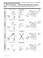
GWS
Gas-Fired Water Boilers
Venting Manual
(Also includes GWS-090E)
Hazard definitions
Hazards that will cause severe personal injury,
death or substantial property damage.
Hazards that can cause severe personal injury,
death or substantial property damage.
Hazards that will or can cause minor personal
injury or property damage.
Special instructions on installation, operation or
maintenance that are important but not related to
personal injury or property damage.
Venting method definitions
Direct vent — Uses outside combustion air with combustion air
connector piping sealed at all joints and seams. Also known as
“sealed combustion”. All GWS and GWS-090E flue gas vents are
pressurized, requiring careful sealing of all joints.
Direct exhaust venting — Uses inside combustion air with no
combustion air connector piping. All GWS flue gas vents are
pressurized, requiring careful sealing of all joints. Also known
as “non-direct venting”. (DO NOT apply direct exhaust venting to
GWS-090E boilers — they must be direct vented only.)
Chimney draft venting — Uses the natural draft provided by
a vertical vent or chimney. (This method cannot be used with
GWS boilers.)
Chimney draft venting cannot be used for GWS
or GWS-090E boilers. Vent system must be constructed only using venting materials listed in this
Venting Manual. Existing vertical vents or chimneys
may only be used as raceways for routing vent or
vent/air piping as described in this Venting Manual.
This Venting Manual must only be used by a qualified
installer/service technician. Read these instructions
completely before beginning the installation. Failure
to follow all instructions in proper order can cause
severe personal injury, death or substantial property
damage.
To install a new vent system follow instructions in:
• This Venting Manual
• GWS or GWS-090E Boiler Manual
• Vent pipe manufacturer’s instructions supplied
with vent material.
DO NOT apply direct exhaust venting for GWS-090E
boilers. These boilers must only be installed as direct
vent.
Contents
Page
1 Determine venting method.........................................2
2 Combustion air supply................................................3
3 Obtain vent system components................................4
4 Install vent starter.......................................................6
5 Vent termination.........................................................7
6 Direct exhaust — Vertical and sidewall venting..........8
7 Direct vent — Sidewall venting.................................10
8 Direct vent — Vertical venting..................................12
INSTALLER — Read all instructions before
installing. Follow all instructions in proper order
to prevent personal injury or death.
Boiler must be vented and supplied with combustion air as described in this manual. Failure to do
so will result in severe personal injury, death or
substantial property damage.
Use only the sealant specified by the vent pipe
manufacturer, applied per their instructions. Vent
piping must be sealed gas-tight to prevent possibility of flue gas spillage and carbon monoxide
emissions, resulting in severe personal injury or
death.
Provide combustion and ventilation air openings
as described in the GWS or GWS-090E Boiler
Manual. Failure to provide adequate air supply
could result in severe personal injury, death or
substantial property damage.
USER — Please read the following. Failure to
comply could result in severe personal injury,
death or substantial property damage.
• This manual is for use only by your qualified
heating installer/service technician.
• Please see the User’s Information Manual for your
reference.
• We recommend regular service by a qualified
service technician, at least annually.
Part Number 550-110-734/1108
GWS Gas-Fired Water Boilers – Venting Manual
1 Determine venting method
To prevent potential of severe personal injury or death, check for areas and products listed in Table 1, page 3, before installing boiler. If found, either remove products permanently or provide outside combustion air (direct vent installation).
Direct exhaust venting
Direct venting
Use only when openings for inside combustion air can be supplied in accordance with the GWS or GWS-090E Boiler Manual,
this venting manual and with all applicable codes. You must direct
vent the boiler if the boiler area may contain contaminants as
described in this manual. Two direct exhaust vent options are
permitted: sidewall and vertical, per instructions in this manual.
See Figure 1, items 1 and 2.
Install an elbow on the air intake fitting as shown
in illustrations in this Venting Manual. This will help
prevent accidental blockage of the air intake.
Combustion air is provided by air piping connecting from the boiler
air intake fitting to the outside.
You must direct vent the boiler (pipe outside air to boiler air
intake fitting) if the boiler area may contain contaminants as
described in this manual.
Two direct vent options are permitted:
1. Direct vent sidewall
— using Vent/Air Intake Termination Kit. See instructions in
this venting manual. Termination kit is included with GWS or
GWS-090E boiler. See Figure 1, item 3.
2. Direct vent vertical
— using Through-Roof or Through-Unused-Chimney Termination Kit. See Figure 1, item 4.
Do not apply to GWS-090E boilers. GWS-090E
boilers must be direct vented.
All GWS-090E boilers must be direct vented (not
direct exhaust).
Figure 1 Venting methods
Do not apply direct exhaust to GWS-090E boilers. GWS-090E boilers must be direct vented.
2
Part Number 550-110-734/1108
GWS Gas-Fired Water Boilers – Venting Manual
2 Combustion air supply
Please review the following information on potential combustion air contamination
problems.
Refer to Table 1 for products and areas that may cause contaminated combustion air.
These contaminants may cause damage to the vent piping, and must be eliminated
from the boiler combustion air supply. You may do this by removing the contaminants
permanently from the area or piping air directly to the boiler (direct vent) using one of
the methods described in this manual.
If the boiler is installed in any area likely to cause contamination, or if
products which would contaminate the air cannot be removed, you must
pipe combustion air to the boiler air intake. Contaminated combustion
air will damage the boiler, resulting in possible severe personal injury,
death or substantial property damage. Do not install a GWS boiler in a
laundry room or pool facility, for example, without using ducted outside
air. These areas will always contain contaminants.
Table 1
Corrosive contaminants
Products to avoid
Spray cans containing chloro/fluorocarbons
Permanent wave solutions
Chlorinated waxes/cleaners
Chlorine-based swimming pool chemicals
Calcium chloride used for thawing
Sodium chloride used for water softening
Refrigerant leaks
Paint or varnish removers
Hydrochloric acid/muriatic acid
Cements and glues
Antistatic fabric softeners used in clothes dryers
Chlorine-type bleaches, detergents, and cleaning solvents found in household laundry rooms
Adhesives used to fasten building products and other similar products
Areas likely to have contaminants
Dry cleaning/laundry areas and establishments
Swimming pools
Metal fabrication plants
Beauty shops
Refrigeration repair shops
Photo processing plants
Auto body shops
Plastic manufacturing plants
Furniture refinishing areas and establishments
New building construction
Remodeling areas
Garages with workshops
Part Number 550-110-734/1108
3
GWS Gas-Fired Water Boilers – Venting Manual
3 Obtain vent system components
Vent and air components
1. The following special gas vent systems comply with UL-1738
and ULC-S636 standards and are certified by CSA as the only
systems suitable for use with GWS and GWS-090E boilers.
Use only 3” vent piping from following:
• Heat-Fab, Inc. Saf-T Vent®
• Flex-L International, Inc. StaR-34
• Z-Flex®, Inc. Z-Vent II
• ProTech Systems FasNSeal™
Use only the vent starter of the same manufacturer
as the vent components. Do not mix components
from different systems. The vent system could fail,
causing flue gas spillage, resulting in severe personal injury or death.
2. Use suitable 3” material for combustion air connector piping,
such as:
Table 2 Direct exhaust and sidewall direct vent
maximum vent length
Maximum vent length
(feet)
Total number of elbows (Notes 1– 3)
1
2
3
4
5
6
GWS-063, -095 &
GWS-090E
55
48
41
34
27
20
GWS-127 & GWS-158
45
38
31
24
17
10
Notes:
1. Do not include termination fitting when counting total number of elbows.
2. One (1) 90° elbow equals two (2) 45° elbows.
3. GWs-090E can only be direct vented.
• Dryer vent
• Galvanized steel
• PVC (3” I.D.)
Direct exhaust and Direct vent sidewall
1. Select vent method based on page 2 and installation requirements.
2. Refer to Table 2 for maximum vent run lengths and number of
elbows. Do not exceed data in Table 2.
3. Select vent components from separate GWI and GWS Vent
Component Supplement. All components, including the vent
starter, must be of the same vent manufacturer. Do not mix
components.
4
Part Number 550-110-734/1108
GWS Gas-Fired Water Boilers – Venting Manual
3 Obtain vent system components
Direct vent vertical
1. The Through-Roof or Through-Unused-Chimney Termination Kit, part number 382-200-436WT, provides special parts
required to route 3-inch stainless vent pipe through 5-inch
B-vent. The space between the vents provides the passage
for combustion air. See Figure 3 for parts included with the
kit.
2. Verify that the vent termination will comply with the requirements listed on page 7. Then verify that the vent and air piping
will not exceed the length limits given in Section 8, page 12 of
this manual before locating boiler or floor/roof penetrations.
3. You will need to obtain stainless vent pipe and fittings, using
only the vent systems listed in separate GWI and GWS Vent
Component Supplement. Also obtain B-vent pipe and fittings
for the vertical run and floor/roof penetrations (See Table 3).
continued
Figure 3 Vertical direct vent — Parts provided in
Through-Roof or Through-Unused-Chimney
Termination Kit (part number 382-200-436WT)
Figure 2 Vertical direct vent — Typical installation,
showing component identification
1 2 3 4 5 6 7 8 Tee, galvanized 5” x 5” x 3” — qty: 1
Vent clamp — qty: 5
Bottom cap, galvanized with 4½” hole — qty:1
Vent support — qty: 1
Elastomer grippers — qty: 11
Screws, sheet metal, type A, #10 x 1¼” — qty: 11
Screws, sheet metal, type A, #10 x ½” — qty: 3
Elastomer flashing — qty: 2
Table 3 Vertical direct vent — Parts
required but not provided in kit
(provided by installer, see Figure 2)
Description
Rain cap, galvanized, 5”
Adjustable flashing, type B, 5”
Fire stop for each floor or attic penetration
Storm ring, type B, 5”
Support, type B, 5”
Draft hood connector, type B, 5”
Adequate B-Vent with clamp rings for combustion air run
(less than 30 feet)
Adequate 3” vent material for vent run and elbows from
one of the following (See Note):
• Heat-Fab, Inc. — Saf-T Vent®
• ProTech Systems — FasNSeal™
• Flex-L International, Inc. — StaR-34
• Z-Flex®, Inc. — Z-Vent II
Adequate sealant specified by vent pipe manufacturer’s
instructions
Quantity
1
1
1
1
1
1
---
--
-Adequate 3” PVC, galvanized or dryer vent (for
combustion air supply piping between tee and boiler)
Note: Do not mix types of vent material. CSA certification will be void.
Part Number 550-110-734/1108
5
GWS Gas-Fired Water Boilers – Venting Manual
4 Install vent starter
Use only the vent starter of the same manufacturer
as the vent components. Do not mix components
from different systems. The vent system could fail,
causing flue gas spillage, resulting in severe personal injury or death.
1. Select a vent pipe manufacturer and obtain all vent components needed, based on boiler location and venting method.
2. You must use the vent starter made by the vent pipe manufacturer. See GWI and GWS Vent Component Supplement,
for part number of each component, listed by vent manufacturer.
3. Follow all applicable national, state, local or provincial codes
when venting the GWS boiler.
4. Connect vent starter to blower housing outlet as shown in
Figure 4, below.
a. Do not mix components from different vent manufacturers.
b. Maintain minimum 2” clearance from combustible materials to
vent pipe. (Exception: PVC air pipe can be no closer than 3/16”
from the vent pipe, as dictated by the dimensions of the vent
termination.)
c. Seal with sealant specified by vent pipe manufacturer, using 3/8”
bead (not required for FasNSeal™).
d. Tighten strap at band clamp screw until strap is snug around
blower housing.
Figure 4 Vent starters
6
Part Number 550-110-734/1108
GWS Gas-Fired Water Boilers – Venting Manual
5 Vent termination
Follow instructions on this page when determining vent location to avoid possibility of severe personal injury, death or
substantial property damage.
1. Locate the boiler and vent penetration through the wall (Direct
exhaust and Direct vent sidewall) or roof (Direct vent vertical)
so all requirements on this page and in Figure 5 will be met.
Also follow vent manufacturer’s instructions.
2. Gases will form white plume in winter. Plume could obstruct
window view of nearby windows in multistory buildings.
3. Prevailing winds could cause freezing of condensate and
water/ice buildup on vent termination, building, plants or roof.
Ice buildup on vent termination can cause boiler shutdown
and building freeze-up.
4. Direct exhaust — Winds over 31 mph can cause nuisance
boiler shutdown if boiler is sidewall vented. This could result
in loss of heat to building, causing freeze-up.
5. Locate or guard vent termination to prevent condensate from
damaging exterior surfaces.
6. Locate the vent termination well away from trees, shrubs, and
decorative items.
7. Locate or guard vent to prevent accidental contact by people
or pets.
8. Do not terminate vent in window well, stairwell, alcove, courtyard, or other recessed areas.
9. Do not wrap or insulate vent pipe or fittings.
10.Direct exhaust and Direct vent sidewall: Do not terminate vent
above any door or window. Condensate can freeze, causing
ice formations.
11.Do not connect:
•
•
Any other appliance to vent pipe.
Multiple boilers to a common vent pipe.
12.Canadian installations — See B149.1 or B149.2 Installation
Code. Terminate vent no less than 6 feet from another combustion air inlet, 3 feet from any other building opening, and
3 feet from any gas service regulator.
13.See Figure 5, showing that the vent must terminate:
•
•
•
•
more than 1 foot (Direct vent) or 4 feet (Direct exhaust) below or
to side of all doors or windows.
more than 1 foot above grade or anticipated snow line.
at least 7 feet above public walkway
3 feet above any forced air intake within 10 feet.
14.Vent must also terminate:
•
•
•
at least 6 feet away from adjacent walls.
no closer than 5 feet below roof overhang.
at least 4 feet horizontally (and in no case above or below unless
a 4 foot horizontal distance is maintained) from electric meters,
gas meters, regulators, relief valves, and other equipment.
15.Site conditions may dictate greater clearances.
16.Direct exhaust and Direct vent sidewall — Do not extend exposed vent pipe outside of building. Condensate could freeze
and block vent pipe.
A gas vent extending through an exterior wall shall not terminate adjacent to the wall or below building extensions such
as eaves, overhangs, balconies or decks. Failure to comply could result in severe personal injury, death or substantial
property damage.
Figure 5 Sidewall Direct Vent or Direct Exhaust Vent — Vent termination minimum clearances
Part Number 550-110-734/1108
7
GWS Gas-Fired Water Boilers – Venting Manual
6 Direct exhaust — Vertical and sidewall venting
Do not apply to GWS-090E boilers. GWS-090E boilers must be direct vented.
Installation guidelines
Figure 6 Direct exhaust vertical or sidewall venting
1. Do not mix types or manufacturers of vent materials.
2. Clean all joints before sealing. See vent manufacturer’s instructions for cleaning and sealing joints. Use their specified
sealant. Do not use screws.
3. Install vent pipe with seams on top of vent horizontal runs.
Follow requirements on page 6 for vent termination.
4. Maintain minimum 2” clearance from combustible materials
to vent pipe.
5. Vertical venting — See Figure 6. Follow vent manufacturer’s
instructions for venting through roof (or unused chimney or
vent as raceway).
•
•
•
Vent pipe must extend through roof flashing, jacket or thimble.
Vent may pass through floor, inside wall or concealed space when
installed according to vent manufacturer’s instructions.
Vent may pass through an unused chimney or vent as a raceway
if allowed by vent manufacturer and installed per vent manufacturer’s instructions.
Sidewall venting — See Figure 7, page 9. Vent must terminate at least one foot above anticipated snowline. Vent must
be terminated only with:
•
•
Tee or elbow with integral screen. (Tee may be mounted either
vertically or horizontally.)
Elbow or termination coupling with screen (not available for StaR34).
Install an elbow on the air intake fitting as shown
in illustrations in this Venting Manual. This will help
prevent accidental blockage of the air intake.
6. Sidewall venting — Do not seal vent pipe to inside or outside
plate.
7. Sidewall venting — If passing through noncombustible wall,
provide hole diameter large enough to insert the vent pipe.
8. Install horizontal drain tee as close as possible to boiler, in
first horizontal run. See Figure 6.
9. Do not exceed the maximum vent system length given in
Table 3 on page 4.
Condensate drain line — use only silicone tubing
rated for at least 400 °F for the first 18” of condensate drain line, then other non-metallic tubing may
be used. Using any other material could cause flue
gas leakage, potentially resulting in severe personal
injury, death or substantial property damage.
On some installations, the condensate drain fitting
may be omitted, provided:
• Vent manufacturer shows this option in their instructions.
• Vent is sloped toward termination as shown in dotted
lines in Figure 6.
• The vent is installed per boiler manufacturer’s and
vent manufacturer’s instructions.
Condensate drippage from such vents may accumulate on the
ground below. Consider traffic in the area to avoid hazard due to
ice accumulation.
8
Part Number 550-110-734/1108
GWS Gas-Fired Water Boilers – Venting Manual
6 Direct exhaust — Vertical and sidewall venting
cont.
Do not apply to GWS-090E boilers. GWS-090E boilers must be direct vented.
Figure 7 Direct exhaust sidewall venting termination
Part Number 550-110-734/1108
9
GWS Gas-Fired Water Boilers – Venting Manual
7 Direct vent — Sidewall venting
termination cap and outside plate with any exterior building
material, such as siding or wood.
Installation guidelines
1. Install vent and air piping in accordance with the GWS or
GWS-090E Boiler Manual, this Venting Manual and with
all applicable national, state, provincial and local codes. In
Canada, see B149.1 or B149.2 Installation Code.
2. Do not mix types or manufacturers of vent materials.
3. Clean all joints before sealing. See vent pipe manufacturer’s
instructions for cleaning and sealing joints. Use their specified
sealant. Do not use screws.
4. Install vent pipe with seams on top of vent horizontal runs.
Follow requirements on page 7 for vent termination.
5. Maintain minimum 2” clearance from combustible materials to
vent pipe. Exception: PVC air pipe can be no closer than 3/16”
from the vent pipe, as dictated by the dimensions of the vent
termination.
6. See Figure 8. Vent must terminate at least one foot above
anticipated snow line.
7. Install horizontal drain tee as close as possible to boiler, in
first horizontal run. See Figure 8.
8. Do not exceed the maximum length given in Table 3, page 4,
for either the vent pipe or the air pipe.
Install Vent/Air Intake Termination
Use this kit with wall thicknesses of 2 inches minimum, 24 inches maximum.
1. Refer to Figure 9 on page 11 for installation details.
2. Remove the sidewall vent kit box from boiler. The kit should
include the following items:
• vent termination cap • screws
• aluminum inside plate
• spacers
• stainless steel outside plate • lockwashers
• anchors for masonry walls
3. Sidewall venting can be installed with pipes side-by-side or on
top of one another with vent pipe on top. Do not cover up vent
4. Cut a 5” x 8½” rectangular rough opening in inside and outside
walls for vent pipe and, if used, combustion air pipe. Use paper
template provided with kit.
Sealant recommended by vent pipe manufacturer
must be used as indicated in their instructions. Vent
piping must be sealed gas-tight to prevent possibility
of flue gas spillage and carbon monoxide emissions,
resulting in severe personal injury or death.
Follow vent manufacturer’s instructions for support
of vent pipe. Do not support from termination kit.
From outside the building
5. Install outside plate.
6. Loosely install vent pipe (with vent pipe termination in place)
through the termination cap and outside plate. Do not connect
pipe or seal to plate.
From inside the building
7. Install spacers and sleeve (if passing through combustible
wall).
8. Install inside plate. If used, feed combustion air pipe through
inside and outside plates.
From outside the building
9. Use termination cap to position combustion air pipe against
stops on the inside of termination cap.
10.Seal outside plate to building. Seal around combustion air
pipe.
11.Install termination cap. Set ¼” to ¾” space between outside
plate and stop on vent pipe termination.
From inside the building
12.Seal around air intake pipe on inside plate.
13.Complete vent pipe run to vent starter at boiler. (See page 11
for air piping instructions.)
Figure 8 Direct vent sidewall venting termination
10
Condensate drain line
— use only silicone
tubing rated for at least 400 °F for the
first 18” of condensate drain line, then
other non-metallic tubing may be used.
Using any other material could cause
flue gas leakage, potentially resulting
in severe personal injury, death or
substantial property damage.
Part Number 550-110-734/1108
GWS Gas-Fired Water Boilers – Venting Manual
7 Direct vent — Sidewall venting
continued
Sidewall direct-vented vent pipe must terminate with coupling as shown in Figure 9. Failure to do so could result in flue
gas recirculation, with the potential of severe personal injury or death.
If you remove the air piping from an existing direct-vented installation, to change to direct exhaust venting, you must
replace the termination coupling with a down-turned termination elbow with screen or a termination tee with screen as
shown in Figure 6, page 8 and Figure 7, page 9. Failure to do so could result in nuisance outages and loss of heat, with
potential substantial property damage.
Figure 9 Termination assembly
Install combustion air piping
Sidewall venting multiple GWS boilers
1. Seal all combustion air piping joints and seams, using sealant
as below:
Do not connect multiple boilers to the same vent.
Failure to comply could result in severe personal
injury, death or substantial property damage.
1. Space terminations apart as shown in Figure 10, below.
a. Dryer vent — A piece of 3” galvanized is required at each end
to adapt. Seal all pipe joints and seams between pipe and dryer
vent with approved silicone sealant (see NOTICE below).
b. Galvanized pipe — Seal all joints and seams using approved
silicone sealant (see NOTICE below).
c. PVC pipe — Seal all joints using PVC cement.
Figure 10 Venting multiple GWS boilers
Except where noted otherwise above, seal air piping
using either the sealant specified by the vent pipe
manufacturer for vent joints or one of the following
silicone sealants:
• Dow Corning 700™ or 732™
• General Electric 108 or 800
Support the air piping in the same manner as specified for the vent pipe by the vent pipe manufacturer.
Do not support the air pipe from the sidewall termination.
Part Number 550-110-734/1108
11
GWS Gas-Fired Water Boilers – Venting Manual
8 Direct vent — Vertical venting
Installation guidelines
1. Codes — Install vent and combustion air piping in compliance
with all applicable national, state, local or provincial codes.
2. Do not connect:
•
Any other appliance to combustion air or vent piping.
•
Any other appliance into or through chimney when using existing
chimney as raceway.
•
Multiple boilers into common vent.
3. Vent length limits — Position boiler as close as possible to
vertical vent/air run. Do not exceed vent length limits given
in Section 8 of this manual. B-vent limit is 30 feet. Vent or air
maximum lengths are:
•
GWS-063, GWS-095 & GWS-090E: Max 55 equivalent feet
•
GWS-127 & GWS-158: Max 45 equivalent feet
4. Materials and construction —
•
Seal all B-vent combustion air joints with approved silicone sealant (Dow Corning 700™ or 732™, General Electric 108 or 800,
or sealant specified by vent pipe manufacturer. B-vent sections
must be straight — no elbows.
•
Construct vent joints per vent manufacturer’s instructions, including use of their specified sealant. Vent pipe routed inside B-vent
must also be fitted with vent clamps with elastomer grippers,
installed per “Installation — Assembly”, pages 14 and 15 of this
manual.
•
Use only one of the approved vent systems listed in Table 2,
page 4. Do not mix types of vent material. CSA certification will
be void.
5. Install boiler per GWS or GWS-090E Boiler Manual.
Verify vent system length
The vent or air piping must be no longer than the maximum value
given in Tables 4 and 5. Note in the tables that the maximum
length of connector piping (vent or air piping between boiler and
B-vent tee connection) depends on the number of elbows and
the length of the B-vent section. The reason is each 90-degree
vent or air pipe elbow cause the same pressure drop as 7 feet
of straight pipe.
Vent/air piping length verification procedure:
Step 1 — Determine dimensions of vent/air pipe needed
for planned location
Measure or calculate the vent/air pipe lengths required for the
planned location of the boiler and floor/roof penetrations. See
Figure 11 for a typical layout.
• How long will the vertical B-vent section have to be? Round
up to the nearest 5 feet (for example, if B-vent length needs to
be 12 feet, round this amount up to the nearest 5 feet — use
15 feet for your B-vent length). (This is dimension L in Figure
11.)
• How many elbows will be needed in the vent connector piping
(from boiler to B-vent tee)?
• How many feet of vent piping will be needed for the connector runs? (This would be the sum of dimensions C & D in
Figure 11.)
• How many elbows will be needed in the air connector piping
(from boiler to B-vent tee)?
• How many feet of air piping will be needed for the connector
runs? (This would be the sum of dimensions A & B in Figure 11.)
Step 2 — Verify that vent connector piping is within allowable limits
Use Table 4 or 5, depending on boiler model to be used. Find the
row with the B-vent length the installation requires. Move across
to the column with the number of vent elbows needed for the installation. This number is the maximum allowable vent connector
piping length.
Step 3 — Verify that air connector piping is within allowable limits
Use Table 4 or 5 on page 13, depending on boiler model to be
used. Find the row with the B-vent length the installation requires.
Move across to the column with the number of air pipe elbows
needed for the installation. This number is the maximum allowable
air pipe connector piping length.
Step 4 — Replan boiler location & piping if piping length
of vent or air is too long
See if boiler can be moved closer to vertical vent/air piping.
See if you can reduce the number of elbows required vent piping
must have 2 elbows minimum in order to provide horizontal piping
to install condensate drain tee.
Vertical venting multiple GWS boilers
1. Multiple GWS boilers may be vented with vent terminations at
the same height. Space terminations to provide a minimum of
1 foot between pipes for U.S. installations. For Canadian installations, provide clearances required by B149.1 and B149.2
Installation Code. Refer to Figure 10 on page 11.
12
Part Number 550-110-734/1108
GWS Gas-Fired Water Boilers – Venting Manual
8 Direct vent — Vertical venting
continued
Example verification (Figure 11):
Figure 11 Typical vent/air piping
Step 1 — Vent/air piping required per plan
As an example, consider an installation of a GWS-127 boiler, where the boiler and vent/
air locations would require:
• Boiler model = GWS-127.
• B-vent length (L) = 20 feet.
• Vent connector piping requires 2 elbows.
• Vent connector piping length (D + C) = 16 feet.
• Air connector piping requires 1 elbow.
• Air connector piping length (B + A) = 17 feet.
Step 2 — Verify vent piping
• Enter Table 5 at the row for B-vent length of 20 feet.
• Move to the 2-elbow column.
• Read a maximum connector pipe length of 18 feet.
Conclusion — Vent piping is within limits because vent connector piping would only
be 16 feet (less than the maximum of 18 feet).
Step 3 — Verify air piping
• Enter Table 5 at the row for B-vent length of 20 feet.
• Move to the 1-elbow column.
• Read a maximum connector pipe length of 25 feet.
Conclusion — Air piping is within limits because air connector piping would only be
17 feet (less than the maximum of 25 feet).
Step 4 — Replanning
No replanning needed. Vent and air piping lengths are within limits.
Table 4
GWS-063, -095 & GWS090E Maximum connector
pipe length, vent or air:
Table 5
GWS-063, GWS-095 & GWS-090E
“B-Vent”
length
(feet)
L
1
5
43
36
29
22
15
8
10
38
31
24
17
10
15
33
26
19
12
20
28
21
14
25
23
16
30
18
11
GWS-127 and GWS-158
Total number of elbows
2
GWS-127 and GWS-158
Maximum connector pipe
length, vent or air:
“B-Vent”
length
(feet)
L
1
1
5
33
26
19
12
5
--
--
3
--
10
28
21
14
7
--
--
--
5
--
--
15
23
16
9
2
--
--
--
7
--
--
--
20
18
11
4
--
--
--
--
9
2
--
--
--
25
13
6
--
--
--
--
--
4
--
--
--
--
30
8
1
--
--
--
--
--
3
4
5
6
7
Max. length from boiler to
“B-Vent”
Note:
Combustion air connector
pipe length = A + B
Vent connector pipe length = C + D
Part Number 550-110-734/1108
Total number of elbows
2
3
4
5
6
7
Max. length from boiler to
“B-Vent”
Note:
Combustion air connector
pipe length = A + B
Vent connector pipe length = C + D
13
GWS Gas-Fired Water Boilers – Venting Manual
8 Direct vent — Vertical venting
continued
Installation — Assembly
Step 1 — Assemble B-vent piping
1. Install 5” type B support, B-vent combustion air run, flashing, fire stops and
storm collar per manufacturer’s instructions. Apply approved sealant to each
B-vent joint. See Figure 12.
2. Install type B draft hood connector to
bottom of combustion air run. Seal with
approved sealant.
Figure 12 Sealing B-vent joints
87305
Step 2 — Prepare and insert
vertical vent
Figure 13 Apply elastomer strips to
vent clamps
1. From top or bottom of combustion air
run, install vent piping.
•
•
Top of vent piping must extend 3” above
top of rain cap. See Figure 2, page 5.
Bottom of vent piping must extend 18”
below draft hood connector.
2. At each vent joint:
a. Follow vent pipe manufacturer’s instructions to assemble and seal joints.
Sealant recommended by vent pipe
manufacturer must be used as indicated in their instructions.
b. Apply 2 self-adhesive elastomer grippers to vent clamp. Grippers must be
positioned on clamp as shown in Figure
13. Bend out 2 ears on vent clamp.
c. Fasten clamp around vent pipe with 2
– 11/4” screws in top and bottom holes,
about every 5 feet. See Figure 14.
Tighten screws until clamp does not
turn or slide around vent piping.
Step 3 — Install vent support
87306
Figure 14 Install vent clamps on
vent piping
Figure 15 Install vent support
1. Apply 1 elastomer gripper to vent support.
2. Install vent support around vent piping just below draft hood connector
as shown in Figure 15. Fasten support around vent piping with 1 – 11/4”
screw.
3. Tighten screw until support does not
turn or slide around vent piping.
14
Part Number 550-110-734/1108
GWS Gas-Fired Water Boilers – Venting Manual
8 Direct vent — Vertical venting
continued
Installation — Assembly continued
Follow vent pipe manufacturer’s instructions to assemble and seal joints. Sealant recommended by vent pipe manufacturer must be used as indicated in their instructions. Vent and combustion air connector piping must be sealed gas-tight
to prevent possibility of flue gas spillage and carbon monoxide emissions, resulting in severe personal injury or death.
Step 4 — Install 5” x 5” x 3” tee
Figure 16 Install tee
1. Slide tee over vent piping and attach uncrimped end to bottom
of draft hood connector:
a. Drill 3 holes in tee for 1/4” sheet metal screws.
Do not allow drill to penetrate vent pipe. Drill holes
carefully in tee and use only 1/4” screws to fasten
tee to draft hood connector. Failure to do so can
damage vent pipe, causing severe personal injury
or substantial property damage.
b. Seal all seams and screws with approved sealant.
2. Secure bottom cap to tee with duct tape. Slide elastomer
flashing up around vent pipe and tuck lip into cap’s bottom
opening. Seal with approved sealant.
Step 5 — Install rain cap
Figure 17 Install rain cap
1. On roof, cut 4 1/2” hole in top of rain cap and install cap over
protruding vent pipe. Slide elastomer flashing down around
vent pipe and tuck lip into cap’s top opening.
2. Connect termination coupling to vent pipe using vent pipe
manufacturer’s specified sealant.
Step 6 — Finish installation
1. Complete vent piping to boiler, making sure to follow vent pipe manufacturer’s instructions and vent manufacturer’s special gas
vent system vent and combustion air venting supplements.
2. Use any of the following to install combustion air connector piping from tee to boiler, making sure to seal all joints and seams:
a. 3” Flexible dryer vent — A piece of 3” galvanized is required at each end to adapt. Seal all pipe joints and seams between pipe and dryer vent
with approved sealant.
b. Galvanized or aluminum single wall pipe — Seal all joints and seams using approved sealant.
c. 3” PVC — Seal all joints using PVC cement.
3. Condensate drain line — A condensate drain fitting is always required for through-roof vents. Follow vent manufacturer’s instructions to install condensate drain line.
Use only silicone tubing rated for at least 400 °F for the condensate drain line. Using any other material could cause flue
gas leakage, potentially resulting in severe personal injury, death or substantial property damage.
Part Number 550-110-734/1108
15
W-T
8201 W. Calumet Rd.
Milwaukee, WI 53223
16
Part Number 550-110-734/1108
GWS Gas-Fired Water Boilers – Venting Manual