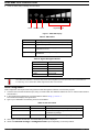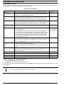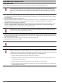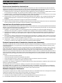
1
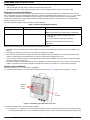
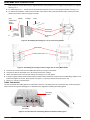
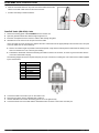
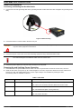
BU/RB MIMO Quick Installation Guide
This Quick Installation Guide describes the installation of the MIMO Bridge Unit/Remote Unit. This guide is intended for
experienced installers. For more information refer to the relevant sections in the System Manual.
CAUTION
ONLY experienced installation professionals who are familiar with local building and safety codes and,
wherever applicable, are licensed by the appropriate government regulatory authorities should install
outdoor units and antennas.
Failure to do so may void the product warranty and may expose the end user or Service Provider to legal
and financial liabilities. The company and its resellers or distributors are not liable for injury, damage or
regulation violations associated with the installation of Outdoor Units or antennas.
français
SEULS les installateurs professionnels expérimentés qui sont familiers avec les codes locaux des bâtiments et
de la sécurité et, lorsque cela s'applique, qui sont autorisés par les autorités gouvernementales de régulation,
doivent installer les unités extérieures et les antennes. Le non-respect de cette clause peut invalider la garantie
du produit et exposer l'utilisateur final ou le prestataire de services à des responsabilités légales et financières.
Le fabricant et ses revendeurs ou distributeurs ne sont pas responsables pour toute blessure, dommage ou
violation de la réglementation associée à l'installation d'unités extérieures ou d'antennes.
Italiano
ATTENZIONE: SOLO professionisti esperti che hanno familiarità con le norme di costruzione locali e coi codici
di sicurezza e, ove applicabile, sono autorizzati dalle autorità governative competenti possono installare unità
esterne ed antenne. Assicurarsi che le unità esterne, antenne e strutture di supporto siano installate
correttamente per eliminare ogni pericolo fisico a persone o cose. In caso contrario, ciò può invalidare la
garanzia del prodotto e può esporre l'utente finale o il fornitore di servizi a responsabilità legali ed economiche.
Anche quando la messa a terra non è obbligatoria in base alla normativa regolatoria applicabile e ai codici
nazionali, è obbligatorio garantire che l'unità esterna e il palo dell'antenna siano messi a terra e idonei dispositivi
di protezione contro i fulmini siano utilizzati in modo da fornire protezione contro le sovratensioni e le scariche
statiche. In ogni caso, il Fornitore e i suoi rivenditori non sono responsabili per eventuali danni fisici, danni ad
oggetti o violazioni del regolamento associati con o causati dall' installazione, la messa a terra o di protezione
contro i fulmini.
Package Content
The BU/RB units are available in packages of single, 10, or 50 units. The following list describes the content of a package with a
single unit.
•
•
•
•
•
One BU/RB unit (either B350, or B350D)
One indoor power supply unit (IDU)
Two power cables (one with a European plug and one with a USA plug)
Sealing gland fastening tool
One mounting kit:
»
»
»
»
»
»
»
»
»
One carriage
One tilting bracket
Two metal clamps
One hook
M8 threaded rods
M8 hex nuts
M8x20 hex screws
M8 flat washers
M8 spring washers
Additional Equipment and Tools required for Installation
• An external antenna (for B350D models only)*
• Antenna cables (for B350D models only)*
• Optional: service (serial) cable*
• A straight outdoor Cat.5e Ethernet cable (FTP 4x2x24 AWG 100 Ohm 8P8C) with two shielded RJ-45 connectors for
•
•
•
•
connecting the IDU to the ODU. This cable is available in various lengths: 20m, 30m, 50m, 70m, 90m, or a drum of 250m*
(see instructions herein on preparing the cable)
4 metal bands for installing the BU/RB on 4”-6” poles*
Mains plug adapter or termination plug (if the power plug on the supplied AC power cable does not fit local power outlets)
A PC/Notebook for configuring the BU/RB unit
Crimping tool for assembling the ethernet connectors
*. Items marked with an asterisk (*) are available from the manufacturer
P/N 215998
-1-
March 2012
BU/RB MIMO Quick Installation Guide
•
•
•
No.13 wrench
Isolation materials. Use high quality cold shrink for the antenna connectors
Grounding cable with at least 18 AWG gauge and with a closed loop (lug) terminal crimped to the ground cable
Equipment Location Guidelines
The BU/RB unit can be installed on straight or angled poles (±45° from upward position) and on a flat surface, such as walls.
Each unit package includes a tilt bracket that allows pole or wall mount installation with up/down tilt of +7.5° to -10°, and rotation
of ±45°. Select the orientation and installation mode according to the Radio Planning and Site Survey recommendations.
The BU/RB unit (depending on the model) is offered with either integrated antenna or external antenna. The following table
details the options for each model.
Follow the installation guidelines provided with the external antennas.
Table 1: Antenna Configuration Options
Model
Integrated Antenna
External Antenna
BU/RB-B350-5X
23 dBi 8 deg, dual polarization
N/A.
BU/RB-B350D-5X
N/A
Note: The two antenna connectors are not operational.
•
•
High gain dish: 28 dBi 2” parabolic dish, dual
polarization
Low gain antenna: 23 dBi dual polarization
Note: Only two of the antenna connectors are
operational.
Select the optimal locations for the equipment using the following guidelines:
•
•
•
•
•
The outdoor unit can be either pole or wall mounted. Its location should enable easy access to the unit for installation and
testing.
The higher the placement of the antenna, the better the achievable link quality.
ODU units with a detached antenna (D model) should be installed as close as possible to the antenna (to ensure that the
antenna's characteristics are not affected by the ODU, the distance must be higher than 10 cm).
The ODU with its integrated antenna (or the detached antenna) should be installed to provide a direct, or near line of sight
with the antenna on the other side.
The indoor equipment should be installed as close as possible to the location where the indoor-to-outdoor cable enters the
building. The location of the indoor equipment should take into account its connection to a power outlet and the CPE.
Outdoor Unit Installation
Mount the ODU unit on a 1"-4" pole using the supplied kit:
1
Assemble the tilt bracket on the unit and fasten the M8 screws (see Figure 1). Apply torque of 80 [Lib*In] = 9 [N*m].
Holes for
M8x20
screws
Tilt
Bracket
Figure 1: Assembling the Tilt Bracket on the Unit
2
Install the carriage using one of the following methods:
»
For poles up to 4” - Thread the four rods through the carriage. Insert the threaded rods with the grooves pointing outward,
as these grooves enable you to use a screwdriver to fasten the rods to the unit. Attach the carriage and the clamps to the
P/N 215998
-2-
March 2012
BU/RB MIMO Quick Installation Guide
pole and tighten on both sides using the supplied washers, spring washers and nuts. Apply torque of 80 [Lib*In] = 9 [N*m].
See Figure 2.
»
»
For poles larger than 4” - Thread the four metal bands through the grooves on the carriage and fasten. See Figure 3.
For wall mount installation - Mark the exact location of the holes to drill on the wall. Drill the holes, and use four metal
dowels and screws to affix the carriage to the wall.
Nuts,
washers and
spring
washers
Clamps
Carriage
Rods
Tilt fastening
screws(x2)
Tilt Control
screw
Figure 2: Assembling the Carriage on 1.5"-4" Poles Using Clamps
Metal bands
Tilt Control screw
Figure 3: Assembling the Carriage on Poles Larger than 4" Using Metal Bands
3
4
5
6
7
Insert the Tilt Control screws into the middle-side hole of the carriage on both sides.
Hang the unit with the tilt bracket on the Tilt-control screws of the carriage.
Attach and fasten all the screws at both sides of the carriage. Do not over tighten.
If required, slightly release the tilt bracket screws to enable rotation and the Tilt Control screws to enable tilting; adjust the unit
position and tighten the screws. Apply torques of 45 [Lib*In.] = 5 [N*m] to the M6 Tilt-control screws, and
80 [Lib*In] = 9 [N*m] to the M8 screws.
Cable Connection
The unit is provided with sealing glands on all the cable connectors. The cables are to be connected to the unit by inserting the
cable connector through the sealing gland. A dedicated tool is supplied for fastening the sealing glands.
Grounding
Terminal
USB/RS-232
For Debug
PoE In
PoE Out
Figure 4: Unit Connections with Sealing Glands and Gland Fastening Tool
P/N 215998
-3-
March 2012
BU/RB MIMO Quick Installation Guide
Grounding Cable
Connect one end of a grounding cable to the grounding terminal and tighten the grounding screw firmly. Connect the other end of
the grounding cable to a good ground (earth) connection.
Antenna Cables
Note that the antenna connectors labeled ANT 5 and ANT 6 are not operational in either the model with the integrated antenna
(BU/RB-B350-5X) or in the model with external antenna (BU/RB-B350D-5X).
ANT 1 ANT 2
ANT 5
ANT 6
Figure 5: RF Connectors
Connecting the Antenna Cables
Connect one end of the coaxial RF cable (LMR 400) to the RF connector labeled ANT 1 on the unit (see Figure 5).
1
2
3
4
5
6
Slide the cold shrink sleeve onto the cable before connecting the cable. See below instructions on sealing the connectors.
Connect the other end of the RF cable to the antenna.
Repeat for the second RF cable (and connect to the RF connector labeled ANT 2).
Seal the RF connectors to protect against rain and moisture. See below instructions.
Fix the RF cable onto the pole using Velcro® wide adjustable straps.
»
If possible, use additional straps to route the cable such that water can accumulate on the cable bends, away from the
unit.
»
When routing the cable, do not exceed the minimum bending radius in the cable specifications.
Sealing the Antenna Cables
Use high quality cold shrink sleeves to seal the connectors.
1
Cut the cold shrink sleeve to size. Take into account the size of the
unit’s connector and additional 2.5 cm (1 in.).
2
Slide the cold shrink sleeve onto the cable before connecting the cable.
3
Connect the cable.
4
Attach the mastic tape (Scotchfil™ Electrical Insulation Putty) and wrap
it around the connector butting up against the connector. Do not over
stretch.
5
Squeeze to tighten the mastic sealer. Make sure there are no air
bubbles.
P/N 215998
-4-
March 2012
BU/RB MIMO Quick Installation Guide
6
Slide the cold shrink sleeve on top of the connector. Make sure that the
sleeve covers both cable connector and unit connector.
7
Pull the cord slowly to shrink the sleeve.
Data/PoE Cable (IDU-ODU) Cable
1
2
3
4
Remove the sealing gland marked POE In from the outdoor unit.
Open the gland and thread the cable through the gland’s nut.
Insert the uncrimped end of the indoor-to-outdoor cable through the gland.
Assemble an RJ-45 connector to the open end of the cable:
Use a crimp tool for RJ-45 connectors to prepare the wires. Insert them into the appropriate pins and use the tool to crimp the
connector. Make sure to do the following:
»
Remove as small a length as possible of the external jacket. Verify that the external jacket is well inside the sealing cover
when connected to the unit, to ensure good sealing.
»
Pull back the shield drain wire before inserting the cable into the RJ-45 connector, to ensure a good connection with the
connector's shield after crimping.
The following diagram shows the required wire pair pin-to-pin connections, including the color codes used in cables supplied
by the manufacturer.
5
6
7
8
Pin
Wire Color
1
2
3
4
5
6
7
8
Blue
Blue/white
Orange
Brown
Brown/White
Orange/white
Green
Green/white
Connect the cable to the POE In port on the outdoor unit.
Reconnect the gland. Use the dedicated tool to fasten it.
Use the dedicated tool to fasten the sealing gland’s nut on the gland’s body.
Connect the other end of the cable with the assembled RJ45 connector to the indoor unit’s Out port.
P/N 215998
-5-
March 2012
BU/RB MIMO Quick Installation Guide
Indoor Unit Installation
Connecting and Sealing the IDU-ODU Cable
1
Connect one end of the grounding cable to the grounding terminal on either side of the IDU and tighten the grounding screw
firmly.
Figure 6: IDU Grounding
2
Connect the indoor to outdoor cable to the IDU’s Out port.
CAUTION
3
Do not connect the data equipment to the OUT port. The OUT port supplies DC power to the ODU, and this
may harm other equipment connected to it.
Connect the IN port of the indoor unit to the backhauling equipment using a standard Ethernet cable.
The combined lengths of the Ethernet cables must not exceed 100m.
4
Connect the power cable to the unit's AC socket, located on the rear panel.
Powering Up and Verifying Proper Operation
1
2
Connect the IDU’s AC power cable to the AC mains. The unit can operate with AC mains of 100-240 VAC, 50-60 Hz.
Check the IDU LEDs. Upon power-up, all 3 LEDs will light for 2 seconds, as part of the self-test for the IDU. After these 2
seconds, the "ON" LED will illuminate green. The DC output voltage is now available for powering the ODU.
The following LEDs are available on the IDU:
Table 2: IDU LEDs
Label
Description
Functionality
On
Power indication to the IDU
Green - The IDU is powered by the AC source and DC output is available
Off - ODU is not connected; ODU fault; Bad indoor-outdoor cable
Fault
IDU-ODU connection
Red - Fault detected (see below)
Off - No fault detected (after or during detection)
Connect
Power indication to the ODU
Green - ODU is connected and powered up
Off - No power to the ODU
P/N 215998
-6-
March 2012
BU/RB MIMO Quick Installation Guide
3
Check the ODU LEDs, indicating the unit’s status.
Power Wireless Fault
Signal Strength
Figure 7: ODU LED Display
Table 3: ODU LEDs
LED
Description
Power
Lights if power is supplied to the ODU (56 VDC).
Wireless
Lights at startup and if a wireless link is established.
Fault
Lights at startup and during operation if a fatal or
critical error occurs
Signal Strength
Indicates wireless signal strength if a wireless link is
established
Table 4: Signal Strength Indicator
No. of LEDs On
SNR
1 LED
5 - 8 dB
2 LEDs
8 - 15 dB
3 LEDs
15 - 20 dB
4 LEDs
20 - 25 dB
5 LEDs
Over 25 dB
The SNR measurement is accurate only when receiving data transmissions from the associated unit.
If necessary, use a continuous PING to generate data transmission.
Initial Configuration
Initial configuration can be performed using either the Web Management Interface or the Monitor program.
1
Connect a PC to the PoE In Ethernet port, using a crossed cable. The default IP address is 10.0.0.1 and the subnet mask is
255.255.255.0.
2
In the web browser’s address bar, type the default IP address: http://10.0.0.1.
The web browser displays the login window.
Type in your credentials. The following accounts are available:
3
Table 5: User Accounts
4
5
Username
Default
Description
guest
public
Read-only account. Cannot change any settings.
installer
installer
Account with writing privileges limited to
commissioning settings.
administratoe
private
Administrative account with full privileges.
Click Login to access the web GUI. The Quick Settings Screen is displayed.
Select either Manual settings or Configuration file options depending on the setup method.
P/N 215998
-7-
March 2012
BU/RB MIMO Quick Installation Guide
Configuring Manual settings
In many installations, most of the parameters should not be changed from their default values. However, if change is required,
use the following list of the basic parameters and their default values:
Table 6: Basic Parameters
Parameter
Description
Default
Select type
Base Unit (BU) and Remote Base (RB). For a Point-to-Point link, one end
should be set up as BU (Bridge Unit) and the other end as RB (Remote Bridge).
A change in Unit Type is applied after reboot.
Base Unit
Country code
Applies a country code. Depending on the country code, specific limitations
such as maximum EIRP, available bandwidths, available channels etc. will
apply to radio parameters. A change in Country Code is applied after reboot.
N/A
ESSID
The Extended Service Set IDentifier that identifies the wireless network. Only
units using the same ESSID are allowed to associate - the same ESSID must
be used on both sides of a link. The ESSID can have up to 32 characters.
Antenna type
Indicates whether the unit is using an internal or external antenna.
Depends on the
type of unit.
Antenna gain (dBi)
•
For integrated antennas, this value is automatically enforced to 23 dBi and
is not configurable
•
For detached antennas, sets the antenna net gain. The configured gain
should take into account the attenuation of the cable connecting the antenna
to the unit. In units using certain Country Codes that have some limitations
on allowed EIRP the configuration range for the Antenna gain parameter
may be limited for compliance with these limitations. A change in Antenna
gain is applied after reboot.
23 (read-only),
or 0, deprnding
on type of unit.
Frequency (MHz)
Sets a specific frequency channel to be used by the unit. Selecting Auto
allows the unit to select the lowest frequency in the selected channels list.
N/A
Clicking on Frequency opens the Channel List window.
Data encryption
option
•
•
Encryption key
Applicable only if Data encryption option is set to AES. Sets the encryption
key used by the AES encryption algorithm when it is enabled. A 16
characters long string.
IP Address
Sets the unit’s management IP address.
Subnet Mask
Sets the unit’s management subnet mask.
Default Gateway
Sets the unit’s management default gateway.
Unit location
Sets an optional description for the unit’s location.
Disable - Wireless traffic is unencrypted.
AES
AES - Uses the Advanced Encryption Standard for encrypting the wireless
traffic
Null
uploading unit settings Using the Configuration File
1
2
3
4
Select the Configuration file option button.
Click Browse... A Choose file to upload window opens.
Navigate to the desired configuration file, select it and click Open to upload the file and return to the Quick Settings window.
Click Save.
e
The new configuration file will be applied after reboot.
P/N 215998
-8-
March 2012
BU/RB MIMO Quick Installation Guide
Aligning the ODU
For optimal alignment of the internal antenna, it is recommended to use the Continuous SNR Display option.
Antenna alignment using the SNR bar display or the Continuous SNR Display is possible only after the RB is
associated with a BU. Both units must be operational and configured with the correct basic parameters (see
above). Otherwise, the two units will not be able to synchronize with each other. As the SNR measurement is
performed on received frames, it is recommended to generate traffic in the wireless link (e.g. by a continuous
ping).
1
2
3
4
Point the antenna of the BU (integrated into the front side of the ODU unit, or detached) towards the direction of the RB, and
vice versa. Take into account the direction in both horizontal and vertical planes. See note below regarding using a compass
for intial alignment.
Verify that the power indication of the units is On.
Verify that the Wireless LED of the ODUs is on, indicating wireless link connectivity. If the Wireless LED is off, check that the
basic parameters (see Table 6) are correctly configured. Proper wireless connectivity depends also on wireless link
conditions and correct orientation of the antennas.
Rotate/tilt the antenna of the RB-ODU until the maximum SNR reading is achieved, where at least 1 green LED is on. If you
encounter prolonged difficulty in illuminating the minimum required number of green LEDs, try to improve the reception
quality by placing the antenna at a higher point or in an alternate location.
All LEDs of the SNR bar display are on at SNR level of 25 dB. In many links a better link quality is expected. For
links with a better quality you should always use the Continuous SNR Display option via Telnet (you may also
connect a PC to the unit via the PoE Out connector).
5
6
7
Ensure that the front of the antenna is always facing the location of the BU. However, in certain conditions, such as when the
line of site to the BU is hampered, better reception may be achieved using a reflected signal. In this case, the antenna is not
always directed toward the BU.
After achieving maximum SNR reading, secure the unit/antenna firmly to the pole.
Repeat the process at the side of the BU.
If applicable, verify that the achieved SNR is similar to expected SNR according to Radio Network Planning.
Aligning the Antenna Using a Compass:
Aligning the antenna using a compass takes into account the original azimuth and calculates a new azimuth that
is shifted by ±90° from the actually required azimuth. The idea is to align the outer frame of the antenna so that
it is in line with the new azimuth, which will achieve higher accuracy of initial alignment.
P/N 215998
1
Point the antenna of towards the general direction of the other unit.
2
Depending on whether you are looking from the left or the right side of the antenna, add or subtract 90° to/
from the original antenna azimuth.
3
Identify a reference point on the landscape that is in the direction of the new heading.
4
Using the compass, align the outer frame of the antenna to the newly calculated azimuth, or to the reference
point identified in point 3 above.
-9-
March 2012
BU/RB MIMO Quick Installation Guide
Safety Information
Professional Installation Instructions
Please be advised that due to the unique function supplied by this product, the device is intended for use with our interactive
entertainment software and licensed third-party only. The product will be distributed through controlled distribution channel and
installed by trained professionals and will not be sold directly to the general public through retail store.
1
2
3
4
5
Installation personnel - This product is designed for specific application and must be installed by a qualified person who has
RF and related rule knowledge. The general user shall not attempt to install or change the settings.
Installation location - The product shall be installed at a location where the radiating antenna can be kept 20 cm from nearby
person in normal operation condition to meet regulatory RF exposure requirements.
External antenna - Use only the antennas which have been approved by the applicant. The non-approved antenna(s) may
produce unwanted spurious or excessive RF transmitting power which may lead to the violation of FCC/IC limit and is
prohibited.
Installation procedure - Please refer to Chapter 3 in this manual for the details.
Warning - Please carefully select the installation position and make sure that the final output power does not exceed the limit
set force in relevant rules. The violation of the rule could lead to serious federal penalty.
Instructions d'installation professionnelle
Veuillez noter que l'appareil etant dedie a une fonction unique, il doit etre utilise avec notre logiciel proprietaire de divertissement
interactif . Ce produit sera propose par un reseau de distribution controle et installe par des professionels; il ne sera pas propose
au grand public par le reseau de la grande distribution.
1
2
3
4
5
Installation - Ce produit est destine a un usage specifique et doit etre installe par un personnel qualifie maitrisant les
radiofrequences et les regles s'y rapportant. L'installation et les reglages ne doivent pas etre modifies par l'utilisateur final.
Emplacement d'installation - En usage normal, afin de respecter les exigences reglementaires concernant l'exposition aux
radiofrequences, ce produit doit etre installe de facon a respecter une distance de 20cm entre l'antenne emettrice et les
personnes.
Antenn externe - Utiliser uniiquement les antennes approuvees par le fabricant. L'utilisation d'autres antennes peut conduire
a un niveau de rayonnement essentiel ou non essentiel depassant les niveaux limites definis par FCC/IC, ce qui est interdit.
Procedure d'installation - Consulter le Chapitre 3 de ce document.
Avertissement - Choisir avec soin la position d'installation et s'assurer que la puissance de sortie ne depasse pas les limites
en vigueur. La violation de cette regle peut conduire a de serieuses penalites federales.
Federal Communication Commission Interference Statement
This device complies with Part 15 of the FCC Rules. Operation is subject to the following two conditions: (1) This device may not
cause harmful interference, and (2) this device must accept any interference received, including interference that may cause
undesired operation.
This equipment has been tested and found to comply with the limits for a Class B digital device, pursuant to Part 15 of the FCC
Rules. These limits are designed to provide reasonable protection against harmful interference in a residential installation. This
equipment generates, uses and can radiate radio frequency energy and, if not installed and used in accordance with the
instructions, may cause harmful interference to radio communications. However, there is no guarantee that interference will not
occur in a particular installation. If this equipment does cause harmful interference to radio or television reception, which can be
determined by turning the equipment off and on, the user is encouraged to try to correct the interference by one of the following
measures:
•
•
•
•
Reorient or relocate the receiving antenna.
Increase the separation between the equipment and receiver.
Connect the equipment into an outlet on a circuit different from that to which the receiver is connected.
Consult the dealer or an experienced radio/TV technician for help.
FCC Caution: Any changes or modifications not expressly approved by the party responsible for compliance could void the user's
authority to operate this equipment.
This transmitter must not be co-located or operating in conjunction with any other antenna or transmitter.
For operation within 5.15 ~ 5.25GHz / 5.47 ~5.725GHz frequency range, it is restricted to indoor environment. The band from
5600-5650MHz will be disabled by the software during the manufacturing and cannot be changed by the end user. This device
meets all the other requirements specified in Part 15E, Section 15.407 of the FCC Rules.
Radiation Exposure Statement
This equipment complies with FCC radiation exposure limits set forth for an uncontrolled environment. This equipment should be
installed and operated with minimum distance 165cm between the radiator & your body.
This device is intended only for OEM integrators under the following conditions:
1
2
The antenna must be installed such that 165 cm is maintained between the antenna and users, and
The transmitter module may not be co-located with any other transmitter or antenna.
P/N 215998
-10-
March 2012
BU/RB MIMO Quick Installation Guide
As long as 2 conditions above are met, further transmitter test will not be required. However, the OEM integrator is still
responsible for testing their end-product for any additional compliance requirements required with this module installed.
IMPORTANT NOTE: In the event that these conditions can not be met (for example certain laptop configurations or co-location
with another transmitter), then the FCC authorization is no longer considered valid and the FCC ID can not be used on the final
product. In these circumstances, the OEM integrator will be responsible for re-evaluating the end product (including the
transmitter) and obtaining a separate FCC authorization.
End Product Labeling
This transmitter module is authorized only for use in device where the antenna may be installed such that 165cm may be
maintained between the antenna and users. The final end product must be labeled in a visible area with the following: “Contains
FCC ID: LKT-BULTRA-5”. The grantee's FCC ID can be used only when all FCC compliance requirements are met.
Manual Information To the End User
The OEM integrator has to be aware not to provide information to the end user regarding how to install or remove this RF module
in the user's manual of the end product which integrates this module.
The end user manual shall include all required regulatory information/warning as show in this manual.
Europe - EU Declaration of Conformity
This device complies with the essential requirements of the R&TTE Directive 1999/5/EC. The following test methods have been
applied in order to prove presumption of conformity with the essential requirements of the R&TTE Directive 1999/5/EC:
•
EN60950-1:2006+A11:2009
Safety of Information Technology Equipment
•
EN50385: 2002
Generic standard to demonstrate the compliance of electronic and electrical apparatus with the basic restrictions related to
human exposure to electromagnetic fields (0 Hz - 300 GHz)
•
EN 301 893 V1.5.1: 2008
Broadband Radio Access Networks (BRAN); 5 GHz high performance RLAN; Harmonized EN covering essential
requirements of article 3.2 of the R&TTE Directive
•
EN 302 502 V1.2.1: 2008
Broadband Radio Access Networks (BRAN); 5,8GHz fixed broadband data transmitting systems; Harmonized EN covering
essential requirements of article 3.2 of the R&TTE Directive
•
EN 301 489-1 V1.8.1: 2008
Electromagnetic compatibility and Radio Spectrum Matters (ERM); ElectroMagnetic Compatibility (EMC) standard for radio
equipment and services; Part 1: Common technical requirements
•
EN 301 489-17 V2.1.1: 2009
Electromagnetic compatibility and Radio spectrum Matters (ERM); ElectroMagnetic Compatibility (EMC) standard for radio
equipment and services; Part 17: Specific conditions for 2,4 GHz wideband transmission systems and 5 GHz high
performance RLAN equipment
This device is a 5GHz wideband transmission system (transceiver), intended for use in all EU member states and EFTA
countries, except in France and Italy where restrictive use applies.
In Italy the end-user should apply for a license at the national spectrum authorities in order to obtain authorization to use the
device for setting up outdoor radio links and/or for supplying public access to telecommunications and/or network services.
This device may not be used for setting up outdoor radio links in France and in some areas the RF output power may be limited
to 10 mW EIRP in the frequency range of 2454 - 2483.5 MHz. For detailed information the end-user should contact the national
spectrum authority in France.
Industry Canada statement
This device complies with RSS-210 of the Industry Canada Rules. Operation is subject to the following two conditions: (1) This
device may not cause harmful interference, and (2) this device must accept any interference received, including interference that
may cause undesired operation.
Ce dispositif est conforme à la norme CNR-210 d'Industrie Canada applicable aux appareils radio exempts de licence. Son
fonctionnement est sujet aux deux conditions suivantes: (1) le dispositif ne doit pas produire de brouillage préjudiciable, et (2) ce
dispositif doit accepter tout brouillage reçu, y compris un brouillage susceptible de provoquer un fonctionnement indésirable.
Caution:
(i) the device for operation in the band 5150-5250 MHz is only for indoor use to reduce the potential for harmful interference to cochannel mobile satellite systems;
(ii) the maximum antenna gain permitted for devices in the bands 5250-5350 MHz and 5470-5725 MHz shall comply with the
e.i.r.p. limit; and
P/N 215998
-11-
March 2012
BU/RB MIMO Quick Installation Guide
(iii) the maximum antenna gain permitted for devices in the band 5725-5825 MHz shall comply with the e.i.r.p. limits specified for
point-to-point and non point-to-point operation as appropriate.
(iv) Users should also be advised that high-power radars are allocated as primary users (i.e. priority users) of the bands 52505350 MHz and 5650-5850 MHz and that these radars could cause interference and/or damage to LE-LAN devices.
Avertissement:
Le guide d'utilisation des dispositifs pour réseaux locaux doit inclure des instructions précises sur les restrictions
susmentionnées, notamment :
(i) les dispositifs fonctionnant dans la bande 5150-5250 MHz sont réservés uniquement pour une utilisation à l'intérieur afin de
réduire les risques de brouillage préjudiciable aux systèmes de satellites mobiles utilisant les mêmes canaux;
(ii) le gain maximal d'antenne permis pour les dispositifs utilisant les bandes 5250-5350 MHz et 5470-5725 MHz doit se
conformer à la limite de p.i.r.e.;
(iii) le gain maximal d'antenne permis (pour les dispositifs utilisant la bande 5725-5825 MHz) doit se conformer à la limite de
p.i.r.e. spécifiée pour l'exploitation point à point et non point à point, selon le cas.
(iv) De plus, les utilisateurs devraient aussi être avisés que les utilisateurs de radars de haute puissance sont désignés
utilisateurs principaux (c.-à-d., qu'ils ont la priorité) pour les bandes 5250-5350 MHz et 5650-5850 MHz et que ces radars
pourraient causer du brouillage et/ou des dommages aux dispositifs LAN-EL.
Radiation Exposure Statement:
This equipment complies with IC radiation exposure limits set forth for an uncontrolled environment. This equipment should be
installed and operated with minimum distance 165cm between the radiator & your body.
Déclaration d'exposition aux radiations:
Cet équipement est conforme aux limites d'exposition aux rayonnements IC établies pour un environnement non contrôlé. Cet
équipement doit être installé et utilisé avec un minimum de 165cm de distance entre la source de rayonnement et votre corps.
Disposal of Electronic and Electrical Waste
Disposal of Electronic and Electrical Waste
Pursuant to the WEEE EU Directive electronic and electrical waste must not be disposed of with unsorted waste.
Please contact your local recycling authority for disposal of this product.
P/N 215998
-12-
March 2012