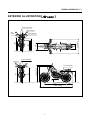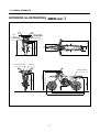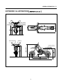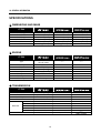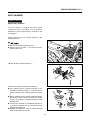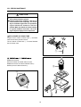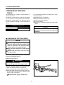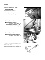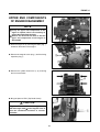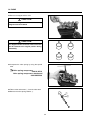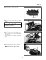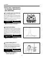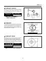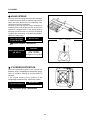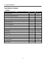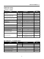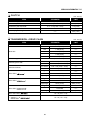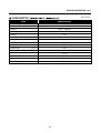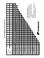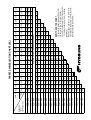
1
RX 125 D
RX 125 SM
RT 125 D
Kun motor. Udgivet 2009
ServiceManual
Holtvej 8-10, Høruphav
6470 Sydals
Telefon: +45 73 15 11 00
Fax: +45 73 15 11 01
E-mail: [email protected]
www.scanmi.dk
CVR: 27 73 31 07
FOREWORD
This manual contains an introductory description on
HYOSUNG『
』,『
』
&『
』 and procedures for its inspection /
service and overhaul of its engine components.
』&
It covers the differences from『
『
』’s engine and please refer to the
service manual of『
(99000-94610)』and
『
(99000-97100)』 for others which are
not covered in this manual.
Other information considered as generally known is
not included.
Read GENERAL INFORMATION section to
familiarize yourself with outline of the vehicle and
MAINTENANCE and other sections to use as a guide
for proper inspection and service.
This manual will help you know the vehicle better so
that you can assure your customers of your optimum
and quick service.
This manual has been prepared on the basis
of the latest specification at the time of
publication.
If modification has been made since then,
difference may exist between the content of
this manual and the actual vehicle.
Illustrations in this manual are used to show
the basic principles of operation and work
procedures.
They may not represent the actual vehicle
exactly in detail.
WARNING
This manual is intended for those who have
enough knowledge and skills for servicing
HYOSUNG vehicles. Without such knowledge and
skills, you should not attempt servicing by relying
on this manual only.
Instead, please contact your nearby authorized
HYOSUNG motorcycle dealer.
NOTE
『
』model :
COPYRIGHT S&T Motors Co., Ltd.
GROUP INDEX
GENERAL INFORMATION
1
PERIODIC MAINTENANCE
2
ENGINE
3
SERVICING INFORMATION
7
HOW TO USE THIS MANUAL
TO LOCATE WHAT YOU ARE
LOOKING FOR :
1. The text of this manual is divided into sections.
2. As the title of these sections are listed on the previous
page as GROUP INDEX, select the section where you are
looking for.
3. Holding the manual as shown at the right will allow you to
find the first page of the section easily.
4. On the first page of each section, its contents are listed.
Find the item and page you need.
SYMBOL
Listed in the table below are the symbols indicating instructions and other information necessary for servicing.
The meaning of each symbol is also included in the table.
SYMBOL
DEFINITION
SYMBOL
DEFINITION
Torque control required.
Data beside it indicates specified torque.
Apply THREAD LOCK“1324”
.
Apply oil.
Use engine oil unless otherwise specified.
Apply or use brake fluid.
Apply SUPER GREASE“A”
.
Measure in voltage range.
Apply SUPER GREASE“C”
.
Measure in resistance range.
Apply SILICONE GREASE.
Measure in current range.
Apply MOLY PASTE.
Measure in diode test range.
Apply BOND“1215”
.
Measure in continuity test range.
Use fork oil.
Use special tool.
2
WIRE COLOR
B
: Black
Gr
: Gray
Sb
: Light blue
L
: Blue
Lg
: Light green
W
: White
Br
: Brown
O
: Orange
Y
: Yellow
G
: Green
R
: Red
BL
: Black with Blue tracer
BBr
: Black with Brown tracer
BG
: Black with Green tracer
BO
: Black with Orange tracer
BR
: Black with Red tracer
BW
: Black with White tracer
BY
: Black with Yellow tracer
LB
: Blue with Black tracer
LG
: Blue with Green tracer
LR
: Blue with Red tracer
LW
: Blue with White tracer
LY
: Blue with Yellow tracer
BrB
: Brown with Black tracer
BrW
: Brown with White tracer
GB
: Green with Black tracer
GR
: Green with Red tracer
GY
: Green with Yellow tracer
GrB
: Gray with Black tracer
GrR
: Gray with Red tracer
GrW
: Gray with White tracer
OB
: Orange with Black tracer
OL
: Orange with Blue tracer
OG
: Orange with Green tracer
OR
: Orange with Red tracer
OW
: Orange with White tracer
OY
: Orange with Yellow tracer
RB
: Red with Black tracer
RW
: Red with White tracer
WB
: White with Black tracer
WL
: White with Blue tracer
WR
: White with Red tracer
YB
: Yellow with Black tracer
YL
: Yellow with Blue tracer
YG
: Yellow with Green tracer
YR
: Yellow with Red tracer
3
4
GENERAL INFORMATION
1
CONTENTS
EXTERIOR PHOTOGRAPH ………………………………………… 6 (1-3)
EXTERIOR ILLUSTRATION~
₩………………………… 7 (1-7-1)
EXTERIOR ILLUSTRATION~
₩……………………… 8 (1-7-2)
EXTERIOR ILLUSTRATION~
₩ ……………………… 9 (1-7-3)
SPECIFICATIONS ………………………………………………………10 (1-8)
5
1-3 GENERAL INFORMATION
EXTERIOR PHOTOGRAPH
6
GENERAL INFORMATION 1-7-1
EXTERIOR ILLUSTRATION~
₩
Rear turn signal lamp
Brake / Tail lamp
Rear
reflector
Front turn signal lamp
Head lamp
230
790
1,125 (HEIGHT)
1,060
945
940
Passenger footrests
1,350 (WHEEL BASE)
2,085 (LENGTH)
7
405
840 (WIDTH)
315
390
715
725
800
865
660
License plate lamp
1-7-2 GENERAL INFORMATION
EXTERIOR ILLUSTRATION~
Brake / Tail lamp
Rear
reflector
840 (WIDTH)
320
410
865
810
720
Rear turn signal lamp
Head lamp
1,160 (HEIGHT)
1,100
3
124cm
295
1,065
Passenger footrests
1,010
875
License plate lamp
Front turn signal lamp
₩
1,425 (WHEEL BASE)
2,190 (LENGTH)
8
GENERAL INFORMATION 1-7-3
EXTERIOR ILLUSTRATION~
Front turn signal lamp
Rear turn signal lamp
(WIDTH)
License plate lamp
Brake / Tail lamp
Head lamp
Passenger footrests
(HEIGHT)
Rear
reflector
₩
(WHEEL BASE)
(LENGTH)
9
1-8 GENERAL INFORMATION
SPECIFICATIONS
⊙ DIMENSIONS AND MASS
ITEM
Overall length
Overall width
Overall height
Wheelbase
Ground clearance
Mass
2,085 mm (82.1 in)
840 mm (33.1 in)
1,125 mm (44.3 in)
1,350 mm (53.2 in)
230 mm (9.1 in)
135 kg (298 lbs)
2,190 mm (86.2 in)
←
1,160 mm (45.7 in)
1,425 mm (56.1 in)
295 mm (11.6 in)
130 kg (287 lbs)
2,175 mm (85.6 in)
←
1,145 mm (45.1 in)
1,415 mm (55.7 in)
275 mm (10.8 in)
←
←
←
←
←
←
←
←
←
←
←
←
←
←
←
←
←
←
←
←
←
←
←
←
←
←
428H, 132 links
←
←
←
←
←
←
←
←
←
428H, 130 links
⊙ ENGINE
ITEM
Type
Number of cylinder
Bore
Stroke
Piston displacement
Fuel system
Starter system
Lubrication system
Four-stroke, DOHC,
Air & oil cooled
1 cylinder
57.0 mm (2.24 in)
48.8 mm (1.92 in)
124.5 ㎤ (7.6 in3 )
Carburetor
Electric starter
Wet sump
⊙ TRANSMISSION
ITEM
Clutch
Transmission
Gearshift pattern
Reduction ratio
1st
2nd
Gear ratio
3rd
4th
5th
Drive chain
Wet multi-plate type
5-speed constant mesh
1-down, 4-up
3.500
2.750
1.786
1.368
1.046
0.913
428SO, 130 links
10
GENERAL INFORMATION 1-9
⊙ CHASSIS
ITEM
Front suspension
Rear suspension
Steering angle
Caster
Trail
Front brake
Rear brake
Front tire size
Rear tire size
Front fork stroke
Telescopic type
Swingarm type
47˚(right & left)
25˚
84 mm (3.31 in)
Disk brake
Drum brake
130/80 - 18M/C 66P
180/80 - 14M/C 78P
160 mm (6.3 in)
←
←
45˚(right & left)
27.5˚
94 mm (3.70 in)
←
←
2.75 - 21 45P
4.10 - 18M/C 59P
250 mm (9.8 in)
←
←
←
27˚
88 mm (3.47 in)
←
Disk brake
110/70 - 17M/C 58H
130/70 - 17M/C 62H
←
←
←
←
←
←
←
←
12 V - H4 : 60 W ×1
12 V - H4 : 55 W ×1
←
←
←
←
←
←
←
←
←
←
←
←
←
←
←
←
←
←
←
←
←
8.0 ℓ
←
←
←
443 ± 2.5 cc
←
←
←
←
←
⊙ ELECTRICAL
ITEM
Ignition type
“CDI”type
6˚B.T.D.C. at 1,900 rpm
and 27˚B.T.D.C. at 4,250 rpm
Spark plug
CR8E
Battery
12 V 6 Ah (MF)
Fuse
15 A
HI
12 V - HS1 : 35 W ×1
LO
12 V - HS1 : 35 W ×1
Head lamp
Position
12 V - W5 W × 1
Turn signal lamp
12 V - RY10 W × 4
Brake / Tail lamp
12 V - P21/5 W × 1
License plate lamp
12 V - W5 W × 1
Illumination lamp
LED type
High beam indicator lamp
12 V - 1.7 W × 1
Turn signal indicator lamp(right & left)
12 V - 1.7 W × 2
Neutral indicator lamp
12 V - 1.7 W × 1
LED : Light Emitting Diode
Ignition timing
⊙ CAPACITIES
ITEM
Fuel tank
Oil change
Engine oil Oil and filter change
Engine overhaul
Front fork oil capacity (One side)
9.0 ℓ
850 ㎖
950 ㎖
1,200 ㎖
215 ± 2.5 cc
NOTE
The specifications are subject to change without notice.
11
12
PERIODIC MAINTENANCE
2
CONTENTS
MAINTENANCE PROCEDURES …………………………………14 (2-3)
CYLINDER HEAD COVER BOLTS,
CYLINDER HEAD & CYLINDER BASE NUTS,
EXHAUST PIPE NUTS AND MUFFLER BOLTS …………………14 (2-3)
AIR CLEANER …………………………………………………………15 (2-5-1)
VALVE CLEARANCE……………………………………………………18 (2-6-1)
SPARK PLUG ……………………………………………………………20 (2-7)
ENGINE OIL ……………………………………………………………21 (2-8)
ENGINE OIL FILTER ……………………………………………………22 (2-9)
CARBURETOR …………………………………………………………23 (2-10)
COMPRESSION PRESSURE CHECK ………………………………24 (2-19)
OIL PRESSURE CHECK ………………………………………………25 (2-20)
13
2
2-3 PERIODIC MAINTENANCE
MAINTENANCE PROCEDURES
This section describes the servicing procedures for
each item.
CYLINDER HEAD COVER BOLTS,
CYLINDER HEAD & CYLINDER
BASE NUTS, EXHAUST PIPE
NUTS AND MUFFLER BOLTS
①
①
Inspect Interval
Tighten Initial at 1,000 km and Every 4,000 km
thereafter.
■ CYLINDER HEAD COVER BOLT
● Tighten the cylinder head cover bolts ① to the
specified torque.
Cylinder head cover bolt
·m (1.2 ~ 1.6 kgf·
·m)
: 12 ~ 16 N·
②
③
■ CYLINDER HEAD & CYLINDER BASE
NUT
● Tighten the cylinder head base buts ② and
cylinder base nuts ③ to the specified torque.
Cylinder head base nut
·m (0.7 ~ 1.1 kgf·
·m)
: 7 ~ 11 N·
Cylinder base nut
·m (0.7 ~ 1.1 kgf·
·m)
: 7 ~ 11 N·
⑦
⑤
■ EXHAUST PIPE NUTS & MUFFLER
BOLTS
⑥
● Tighten the exhaust pipe nuts ④ , muffler
connecting bolt ⑤, and muffler mounting bolts ⑥,
⑦ to the specified torque.
Exhaust pipe nut
·m (1.8 ~ 2.8 kgf·
·m)
: 18 ~ 28 N·
Muffler connecting bolt
·m (1.8 ~ 2.8 kgf·
·m)
: 18 ~ 28 N·
Muffler mounting bolt
·m (1.8 ~ 2.8 kgf·
·m)
: 18 ~ 28 N·
④
14
PERIODIC MAINTENANCE 2-5-1
AIR CLEANER
Inspect Interval
Clean Every 3,000 km,
Replace Every 12,000 km.
If the air cleaner is clogged with dust, intake
resistance will be increased, with a resultant
decrease in power output and an increase in fuel
consumption.
Check and clean the air cleaner element in the
following manner :
①
■
● Remove the seat and right side cover.
● Remove the six screws ① and remove the air
cleaner case cover.
● Take off the air cleaner element ②.
②
Clean the air cleaner element for the follwing :
● Fill a washing pan of a proper size with a nonflammable cleaning solvent . Immerse the air
cleaner element in the cleaning solvent and wash
it.
● Gently squeeze the air cleaner element between
the palms of both hands to remove the excess
solvent : do not twist or wring the element or it will
develop tears.
● Immerse the element in HYOSUNG genuine oil
, and then squeeze out the excess oil leaving
the element slightly wet.
● Reinstall the cleaned or new air cleaner element
in the reverse order of removal.
15
2-5-2 PERIODIC MAINTENANCE
CAUTION
Inspect the air cleaner element for tears.
A torn element must be replaced.
If driving under dusty conditions, clean the air
cleaner element more frequently. The surest
way to accelerate engine wear is to operate the
engine without the element or with torn
element. Make sure that the air cleaner element
is in good condition at all times. Life of the
engine depends largely on this component!
※ AIR CLEANER OIL DRAIN TUBE
Inspect the air cleaner oil drain tube ① and drain
water and oil at the periodic interval.
The air cleaner oil drain tube ① is located beneath
the air cleaner case.
①
■
②
&
● Remove the seat.
● The air cleaner is located under the seat.
● Remove the four air cleaner element bolts ②.
● Pull up the air cleaner element ③.
③
②
8
8
②
16
PERIODIC MAINTENANCE 2-5-3
Clean the air cleaner element for the following :
● When the air cleaner element clean with the air gun,
necessarily blow at the inside by compressed air.
● Carefully examine the air cleaner element for tears
during cleaning. Replace it with a new one if it is torn.
● Assemble the element completely or damage
severely the engine.
● Be careful not to allow water to go inside the air cleaner element.
CAUTION
More frequent servicing may be performed on
motorcycles that are used under severe
conditions, also clean the air cleaner element
when replacing the engine oil to prevent damage
of the engine.
※ AIR CLEANER OIL DRAIN TUBE
Inspect the air cleaner oil drain tube ① and drain
water and oil at the periodic interval.
The air cleaner oil drain tube ① is located beneath
the air cleaner case.
8
8
①
17
2-6-1 PERIODIC MAINTENANCE
VALVE CLEARANCE
Inspect Interval
Inspect Initial 1,000 km and Every 4,000 km
thereafter.
Excessive valve clearance results in valve noise and
insufficient valve clearance results in valve damage
and reduced power.
Check the intake and exhaust valve clearances at
the distances indicated above and adjust the valve
clearances to specification, if necessary.
● Remove the seat and fuel tank.
● Remove the spark plug.
● Remove the cylinder head cover ①.
The valve clearance specification is different for both
intake and exhaust valves.
Valve clearance adjustment must be checked and
adjusted :
1) at the time of periodic inspection,
2) when the valve mechanism is serviced, and
3) when the camshafts are removed for servicing.
①
● Remove the magneto cover plug ② and valve
timing inspection plug ③.
NOTE
The piston must be at top dead center (TDC)
on the compression stroke in order to check or
adjust the valve clearance.
The valve clearance should only be checked
when the engine is cold.
③
②
18
PERIODIC MAINTENANCE 2-6-2
● Rotate the magneto rotor clockwise or counterclockwise with a socket wrench to set the piston at
TDC on the compression stroke.
(Rotate the magneto rotor until the “T” index mark
on the magneto rotor is aligned with the triangle
mark ① on the crankcase.)
①
● To inspect the valve clearance, insert a thickness
gauge between the tappet and the camshaft.
Valve clearance
Standard (When cold)
IN.
0.1 ∼ 0.2 mm (0.004 ~ 0.008 in)
EX.
0.2 ∼ 0.3 mm (0.008 ~ 0.012 in)
Thickness gauge : 09900-20806
● If the clearance is out of specification, first remove
the cam chain tension adjuster, camshaft housing,
camshaft.
To install the tappet shim at original position,
record the shim NO. and clearance to present by
“A”, “B”, “C”, “D” mark on the cylinder head.
Select the tappet that agree with tappet clearance
(vertical line) and shim NO.(horizontal line) as refer
to the tappet shim selection chart.
(Refer to page 90·91)
Adjust valve timing, install the camshaft housing and
the cam chain tension adjuster.
After the crankshaft rotate about 10 times, measure
the valve clearance.
If the clearance be not correct, adjust the standard
clearance as the same manner above.
● In case of valve adjustment which is not the tappet
shim selection chart, please follow instructions of
example in the below.
For example, the intake clearance is 0.4 and the
shim is 170 (1.70 mm), select 195 (1.95 mm) of
the shim which 170 (1.70 mm) of the shim add up
the excess clearance 0.25 mm when adjust with
the standard 0.15 as the intake standard clearance
0.1∼ 0.2 mm.
CAUTION
If you don’t rotate the crankshaft about 10 times
before measuring the valve clearance, there is no
meaning of valve clearance.
19
2-7 PERIODIC MAINTENANCE
SPARK PLUG
Inspect Interval
Clean Initial 1,000 km and Every 4,000 km thereafter.
Replace Every 8,000 km.
①
● Disconnect the spark plug cap ① and remove the
spark plug.
TYPE
SPARK PLUG SPECIFICATION
Hot type
CR7E
Standard type
CR8E
Cold type
CR9E
■ CARBON DEPOSITS
Check to see if there are carbon deposits on the
spark plug.
If carbon is deposited, remove it using a wire or pin
with a pointed end.
■ SPARK PLUG GAP
Measure the spark plug gap using a thickness
gauge.
If the spark plug gap is out of specification, adjust the
gap.
Spark plug gap
0.7 ∼ 0.8 mm (0.028 ~ 0.032 in)
Thickness gauge : 09900-20806
0.7 ~ 0.8 mm
(0.028 ~ 0.032 in)
■ ELECTRODE
Check to see the worn or burnt condition of the electrodes.
If it is extremly worn or burnt, replace the spark plug
with a new one.
And also replace the spark plug if it has a broken
insulator, damaged thread, etc.
CAUTION
To avoid damaging the cylinder head threads ;
first, finger tighten the spark plug, and then
tighten it to the specified torque using the spark
plug wrench.
20
PERIODIC MAINTENANCE 2-8
● Insert the spark plug and finger tighten it to the
cylinder head and then tighten it to the specified
torque.
Spark plug
·m (2.0 ~ 2.5 kgf·
·m)
: 20 ~ 25 N·
ENGINE OIL
Inspect Interval
Replace Initial 1,000 km and Every 4,000 km
thereafter.
Necessary amount of engine oil
Oil change
850 ㎖
Oil and filter change
950 ㎖
Engine overhaul
1,200 ㎖
Engine oil type
SAE 10W/40
API Over SL
Engine oil should be changed while the engine is
warm.
Engine oil filter replacement at the above intervals,
should be together with the engine oil change.
● Keep the motorcycle upright.
● Place an oil pan below the engine, and drain the
engine oil by removing the engine oil filler plug ①
and drain plug ②.
● Reinstall the drain plug gasket and engine oil
drain plug ②.
● Tighten the drain plug ② to the specified torque,
and pour fresh engine oil through the engine oil
filler hole. Use an engine oil that meets the API
service classification of Over SL and that has a
viscosity rating of SAE 10W/40.
①
Engine oil drain plug
: 25 ~ 30 N·m (2.5 ~ 3.0 kgf·m)
● Install the engine oil filler plug ①.
● Start up the engine and allow it to run for a few
minutes at idling speed.
● Turn off the engine and wait about three minutes,
and then check the engine oil level through the
engine oil level lens.
If the level is below mark“F”, add engine oil to
“F”level. If the level is above mark“F”, drain
engine oil to“F”level. The motorcycle must be in
a level position for accurate measurement.
②
21
2-9 PERIODIC MAINTENANCE
CAUTION
Never operate the motorcycle if the engine oil level
is below the“Lower line mark (L)”in the engine
oil level lens. Never fill the engine oil above the
“Upper line mark (F)”.
Engine oil level being most suitable about 1 mm
under the“Upper line mark (F)”of the engine oil
level lens. In case of the engine oil pouring in
excessively, the engine output being made
insufficient.
Be careful not to pour the engine oil excessively
into the engine.
CAUTION
①
Necessarily, confirm and clean the oil strainer ①
when replace the engine oil (specially, when first
replacement).
CAUTION
More frequent servicing may be performed on motorcycles that are used under severe conditions.
ENGINE OIL FILTER
Inspect Interval
②
Replace Initial 1,000 km and Every 4,000 km
thereafter.
● Drain the engine oil as described in the engine oil
replacement procedure.
● Remove the oil filter cap ② by removing the three
nuts.
● Remove the oil filter ③.
● Install the new O-ring ④.
● Install the new oil filter.
● Install the new O-ring ⑤ and spring ⑥ to the oil filter
cap.
● Install the oil filter cap ②.
②
CAUTION
③
Before installing the oil filter cap, apply engine
oil lightly to the new O-ring ⑤.
⑤ ⑥
22
④
PERIODIC MAINTENANCE 2-10
■ OIL FILTER INSTALLATION
INSERTED
DIRECTION
⇦
CAUTION
LUSTER MATERIAL
When installing the oil filter, necessarily,
“HYOSUNG”character and“16510H05240”part’s
NO. is installed toward the outside, otherwise can
damage the engine.
WARNING
HYOSUNG
Engine oil and exhaust pipes can be hot enough to
burn you.
Wait until the engine oil drain plug and exhaust
pipes are cool enough to touch with bare hands
before draining oil.
16510H05240
● Add new engine oil and check the engine oil
level as described in the engine oil replacement
procedure.
CAUTION
ONLY USE A GENUINE HYOSUNG MOTORCYCLE
ENGINE OIL FILTER. Other manufacturer’s
engine oil filters may differ filtering performance
and durability which may lead to engine damage
or oil leaks.
CARBURETOR
Inspect Interval
①
Inspect Initial 1,000 km and Every 4,000 km
thereafter.
■ IDLE SPEED
CAUTION
Make this inspection when the engine is hot.
● Connect an engine tachometer to the high tension
cord.
Start up the engine and set its speed at anywhere
of the specified value by turning throttle stop
screw ①.
Engine idle speed
1,400 ∼ 1,600 rpm
&
Engine idle speed
1,400 ∼ 1,500 rpm
Engine tachometer : 09900-26006
23
⇦
OUTSIDE
2-19 PERIODIC MAINTENANCE
COMPRESSION PRESSURE
CHECK
Low compression pressure can indicate some of the
following conditions :
● Excessively worn cylinder wall
● Worn-down piston or piston rings
● Piston rings stuck in grooves
● Poor valve seating
● Ruptured or otherwise defective cylinder head
gasket
The compression of a cylinder is a good indicator of
its internal condition.
The decision to overhaul the cylinder is often based
on the results of a compression test. Periodic
maintenance records kept at your dealership should
include compression reading for each maintenance
service.
Compression pressure
Standard
14 ~ 16 kgf/㎠
Service limit
12 kgf/㎠
NOTE
When the compression pressure goes below
specification, check the engine for conditions
listed above.
■ COMPRESSION TEST PROCEDURE
NOTE
Before testing the engine for compression
pressure, make sure that the cylinder head
bolts are tightened to the specified torque
values and valves are properly adjusted.
Have the engine warmed up by idling before
testing.
Be sure that the battery used is in fullycharged condition.
Remove the related parts and test the compression
pressure in the following manner :
● Remove the spark plug.
WARNING
The hot engine can burn you.
Wait until the engine are cool enough to touch.
● Fit the compression gauge in the spark plug hole.
Make sure that the connection is tightened.
● Keep the throttle grip in the full-opened position.
● Press the starter switch and crank the engine for a
few seconds. Record the maximum gauge reading
as the cylinder compression.
Compression gauge : 09915-64511
24
PERIODIC MAINTENANCE 2-20
OIL PRESSURE CHECK
Check the engine oil pressure periodically.
This will give a good indication of the condition of the moving parts.
Standard
Oil pressure
0.4 ~ 0.6 kgf/㎠
(at 60 ℃·3,000 rpm)
If the engine oil pressure is lower or higher than the specification, the following causes may be considered.
■ LOW OIL PRESSURE
● Clogged oil filter
● Oil leakage from the oil passage way
● Damaged O-ring
● Defective oil pump
● Combination of the above items
■ HIGH OIL PRESSURE
● Engine oil viscosity is too high
● Clogged oil passage way
● Combination of the above items
■ OIL PRESSURE TEST PROCEDURE
Check the engine oil pressure in the following manner :
● Remove the oil check plug ① and install the oil
pressure gauge and adapter into the oil check plug
removed position.
● Connect an engine tachometer.
● Warm up the engine as follows :
Summer : 10 min. at 2,000 rpm.
Winter : 20 min. at 2,000 rpm.
● After warming up, increase the engine speed
to 3,000 rpm. (with the engine tachometer), and
read the oil pressure gauge.
①
Engine tachometer : 09900-26006
Oil pressure gauge : 09915-74511
25
26
ENGINE
CONTENTS
ENGINE REMOVAL AND REMOUNTING ……………………… 28 (3-5)
ENGINE REMOUNTING ……………………………………………… 28 (3-5)
UPPER END COMPONENTS OF ENGINE DISASSEMBLY 29 (3-6)
UPPER END COMPONENTS OF ENGINE INSPECTION
AND SERVICING ……………………………………………………… 34 (3-11)
UPPER END COMPONENTS OF ENGINE REASSEMBLY 44(3-21)
LEFT END COMPONENTS OF ENGINE DISASSEMBLY
54 (3-31)
RIGHT END COMPONENTS OF ENGINE DISASSEMBLY 57 (3-34)
LOWER END COMPONENTS OF ENGINE DISASSEMBLY 60 (3-37)
LOWER END COMPONENTS OF ENGINE INSPECTION
AND SERVICING ……………………………………………………… 63 (3-40)
LOWER END COMPONENTS OF ENGINE REASSEMBLY 66 (3-43)
RIGHT END COMPONENTS OF ENGINE REASSEMBLY
71 (3-48)
LEFT END COMPONENTS OF ENGINE REASSEMBLY
75 (3-52)
CAUTION
Mark an identification of assembly location on each removed part so that each will be restored to the
original position during reassembly.
Wash clean and dry the removed parts before inspecting and measuring.
Oil the rotating or sliding parts before assembly.
Make sure to use the correct type of lubricant where specified.
Check that each rotating or sliding part moves or operates smoothly after assembly.
Make sure to follow the bolt tightening order where specified.
If the correct length of the bolt is confused when tightening the crankcase or cover, insert all the bolts
and check that the tightening margin is equal in each bolt.
27
3
3-5 ENGINE
ENGINE REMOVAL AND
REMOUNTING
ENGINE REMOUNTING
Remount the engine in the reverse order of removal.
● Temporarily fasten the engine mounting bracket
before inserting the engine mounting bolts.
②
③
● Tighten the engine mounting bolts and nuts to the
specified torque.
①
Engine mounting bolt (M10) ①
·m (4.8 ~ 7.2 kgf·
·m)
: 48 ~ 72 N·
Engine mounting bolt (M8) ②, ③, ④
·m (2.2 ~ 3.3 kgf·
·m)
: 22 ~ 33 N·
④
● Tighten the engine mounting bracket bolts and nuts
to the specified torque.
Engine mounting bracket bolt (M8) ⑤
·m (2.2 ~ 3.3 kgf·
·m)
: 22 ~ 33 N·
⑤
■ INSTALLING POSITION FOR CLUTCH
RELEASE ARM
● Align the clutch release arm slit surface with the
notch mark on the clutch release camshaft.
Notch Mark
Slit
28
ENGINE 3-6
UPPER END COMPONENTS
OF ENGINE DISASSEMBLY
NOTE
If only the upper end components of the
engine is repaired, there is no necessary to
remove the engine from the frame.
Remove the seat and fuel tank so that the
upper end components of the engine is
disassemble.
①
● Drain the engine oil by removing the drain plug ①
located on the bottom of the engine.
● Remove the magneto cover plug ② and the timing
inspection plug ③.
③
②
● Remove the cylinder head cover ④ by removing
the four wrench bolts.
④
● Bring the piston at TDC (Top Dead Center).
CAUTION
”index mark on the magneto rotor
Align the“T”
with the triangle mark ⑤ on the magneto cover as
turn the crankshaft clockwise or counterclockwise.
⑤
29
3-7 ENGINE
● Remove the cam chain tension adjuster ①.
①
● Remove the cam chain guide NO.2 ②.
②
● Remove the camshaft housings ③.
③
● Remove the dowel pins, intake camshaft and
exhaust camshaft.
NOTE
Do not drop the dowel pins and cam chain into
the crankcase.
30
③
ENGINE 3-8
● Remove the camshaft C-rings ①.
①
● Loosen the three cylinder head bolts.
● Loosen the three cylinder head base nuts.
● Remove the cam chain guide NO.1.
31
3-9 ENGINE
● Remove the tappet and the shim.
CAUTION
Draw out the tappet and shim with the strong
magnet not to be scratched.
CAUTION
The tappet and shim should be lined so that each
will be restored to the original position during
reassembly.
● Compress the valve spring by using the special
tools.
Valve spring compressor
: 09916-14510
Valve spring compressor attachment
: 09916H35C00
● Take out the valve cotter ① from the valve stem.
● Remove the valve spring retainer ②.
①
②
32
ENGINE 3-10
● Pull out the valve ① from the other side.
①
● Remove the two cylinder base nuts and the
cylinder.
CAUTION
If tapping with the plastic hammer is necessary,
pay attention to break the fins.
● Place a clean rag over the cylinder base to
prevent the piston pin circlips from dropping into
the crankcase.
Remove the piston pin circlips with the long-nose
pliers.
● Remove the piston pin by using the special tool.
Piston pin puller : 09910-34510
33
3-11 ENGINE
UPPER END COMPONENTS
OF ENGINE INSPECTION
AND SERVICING
⊙ CYLINDER HEAD DISTORTION
Decarbonize in combustion chamber.
Check the gasket surface of the cylinder head for
distortion using a straightedge and thickness gauge.
Take clearance reading at several places as
indicated.
If any clearance reading exceeds the service limit,
replace the cylinder head with a new one.
Cylinder head
Cylinder
head
distortion
distortion
Service limit
0.05 mm (0.002 in)
Thickness gauge : 09900-20806
⊙ VALVE FACE WEAR
Visually inspect each valve face for wear or damage.
If any abnormal wear is found, replace the respective
valve with a new one. The thickness of the valve face
decreases as the face wears. Measure the valve
head thickness . If the valve head thickness is not
within the specified value, replace the valve with a
new one.
Cylinder
head
Valve
head thickness
distortion
(IN. & EX.)
Service limit
0.5 mm (0.02 in)
Vernier calipers : 09900-20101
⊙ VALVE STEM RUNOUT
Check the valve stem for abnormal wear or bend.
Support the valve using a V-blocks and measure the
valve stem runout using the dial gauge, as shown.
If the service limit is exceeded or abnormal condition
exists, replace the valve with a new one.
Cylinder
Valve
stemhead
runout
distortion
(IN.
& EX.)
Service limit
0.05 mm (0.002 in)
Dial gauge : 09900-20606
Magnetic stand : 09900-20701
V-block : 09900-21304
34
ENGINE 3-12
⊙ CAMSHAFT RUNOUT
Support the camshaft using a V-blocks and measure
the camshaft runout using the dial gauge. If the
runout exceeds the service limit, replace the
camshaft with a new one.
Camshaft runout
(IN. & EX.)
Service limit
0.10 mm (0.004 in)
Dial gauge : 09900-20606
Magnetic stand : 09900-20701
V-block : 09900-21304
⊙ CAMSHAFT
。)
TDC (0。
The camshaft should be checked for runout and also
for wear of cams and journals if the engine has been
noted to produce abnormal noise or vibration or a
lack of out-put power. Any of these abnormality could
be caused by a worn camshaft.
Intake open
(B.T.D.C)
Exhaust close
(A.T.D.C)
17。 45。
90。
270。
14。 48。
Intake close
(A.B.D.C)
Exhaust open
(B.B.D.C)
。)
BDC (180。
VALVE TIMING DIAGRAM
⊙ CAMSHAFT WEAR
Worn-down cams are often the cause of mistimed
valve operation resulting in reduced output power.
The limit of cam wear is specified for both intake and
exhaust cams in terms of cam height , which is to
be measured with a micrometer. Replace camshafts
if found it worn down to the limit.
Cam height
Service limit
Intake cam
34.17 mm (1.345 in)
Exhaust cam
34.12 mm (1.343 in)
Micrometer(25~50 mm) : 09900-20202
35
3-13 ENGINE
⊙ TAPPET & SHIM WEAR
When measuring the valve clearance, the clearance
should be within the standard range.
Valve clearance
Standard (When cold)
Intake valve
0.1 ~ 0.2 mm
(0.004 ~ 0.008 in)
Exhaust valve
0.2 ~ 0.3 mm
(0.008 ~ 0.012 in)
Thickness gauge : 09900-20806
● Inspect the tappet for wear and scratch.
If modification or scratch is present, replace the
tappet.
● When you checked the valve clearance, if the
valve clearance is wide please replace the present
shim into thick one, if the valve clearance is
narrow please replace the present shim into thin
shim. (Refer to page 90·91)
⊙ SHIM KIND
There are 41 kinds of shim which thickness is
increased by each 0.025 mm from 1.20 mm to 2.20
mm.
36
ENGINE 3-14
⊙ VALVE HEAD RADIAL
RUNOUT
Support the valve using a V-block and measure the
valve head radial runout using the dial gauge, as
shown. If the runout exceeds the service limit,
replace the valve with a new one.
Cylinder
Valve
headhead
radial
distortion
runout
(IN. & EX.)
Service limit
0.03 mm (0.0012 in)
Dial gauge : 09900-20606
Magnetic stand : 09900-20701
V-block : 09900-21304
⊙ VALVE STEM DEFLECTION
Lift the valve about 10 mm (0.39 in) from the valve
seat. Measure the valve stem deflection in two
directions, “X” and “Y”, perpendicular to each other.
Position the dial gauge as shown.
If the deflection exceeds the service limit, determine
whether the valve or the guide should be replaced
with a new one.
Valve stem deflection
Service limit
IN.
0.35 mm
(0.014 in)
EX.
0.35 mm
(0.014 in)
Dial gauge : 09900-20606
Magnetic stand : 09900-20701
⊙ VALVE STEM DIAMETER
Measure the valve stem outside diameter using the
micrometer.
If the diameter measured exceeds the standard,
replace the valve.
Valve stem diameter
Standard
IN.
4.475 ~ 4.490 mm
(0.1762 ~ 0.1768 in)
EX.
4.455 ~ 4.470 mm
(0.1754 ~ 0.1760 in)
Micrometer(0~25 mm) : 09900-20201
37
3-15 ENGINE
⊙ VALVE SPRING
The force of the coil spring keeps the valve seat tight.
A weakened spring results in reduced engine power
output and often accounts for the chattering noise
coming from the valve mechanism.
Check the valve springs for proper strength by
measuring their free length and also by the force
required to compress them. If the spring length is
less than the service limit or if the force required to
compress the valve spring is not within specification,
replace the valve spring.
Cylinder
head
Valve
spring
free
distortion
length
(IN. & EX.)
Service limit
37.80 mm (1.488 in)
Vernier calipers : 09900-20101
Cylinder head
Valve distortion
spring tension
(IN. & EX.)
Standard
12.1 ~ 13.9 kgf
(26.68 ~ 30.64 lbs)
at length 33.7 mm (1.33 in)
⊙ CYLINDER DISTORTION
Check the gasketed surface of the cylinder for
distortion using a straightedge and thickness gauge,
taking a clearance reading at several places as
indicated.
If the largest reading at any position of the
straightedge exceeds the limit, replace the cylinder.
Cylinder distortion
Service limit
0.05 mm (0.002 in)
Thickness gauge : 09900-20806
38
ENGINE 3-16
⊙ CYLINDER BORE
Measure the cylinder bore diameter at six place.
If any one of the measurements exceeds the limit,
overhaul the cylinder and replace the cylinder.
Service limit
Standard
Cylinder bore 57.000 ~ 57.015 mm
(2.2441 ~ 2.2447 in)
57.080 mm
(2.2472 in)
Cylinder gauge set : 09900-20508
⊙ PISTON DIAMETER
INSPECTION
Measure the outside diameter of the piston in the
direction perpendicular to the piston pin axis at the
height from the skirt as shown in the illustration using
a micrometer.
If the measurement is found less than the service
limit, replace the piston.
Piston diameter
15 mm (0.6 in)
Service limit
56.880 mm (2.2394 in)
Micrometer(50 ~ 75 mm) : 09900-20203
⊙ PISTON TO CYLINDER
CLEARANCE
To determine the piston to cylinder clearance,
calculate the difference between the cylinder bore
and outside diameter of the piston.
Piston to
cylinder
clearance
Standard
Service limit
0.050 ~ 0.060 mm
(0.0020 ~ 0.0024 in)
0.120 mm
(0.0047 in)
39
3-17 ENGINE
⊙ PISTON RING TO GROOVE
CLEARANCE INSPECTION
Remove carbon deposit both from the piston ring and
its groove.
Fit the piston ring into the groove. With the ring compressed and lifted up, measure the clearance on the
bottom side of the ring using a thickness gauge.
If any clearance reading exceeds the service limt,
replace both the piston and piston rings.
Piston ring-groove clearance
Service limit
1st
0.180 mm (0.007 in)
2nd
0.150 mm (0.006 in)
Piston ring groove width
Standard
1st
1.01 ~ 1.03 mm
(0.040 ~ 0.041 in)
2nd
1.01 ~ 1.03 mm
(0.040 ~ 0.041 in)
Oil
2.01 ~ 2.03 mm
(0.079 ~ 0.080 in)
Piston ring thickness
Standard
1st
0.970 ~ 0.990 mm
(0.0382 ~ 0.0390 in)
2nd
0.970 ~ 0.990 mm
(0.0382 ~ 0.0390 in)
Micrometer(0~25 mm) : 09900-20201
Thickness gauge : 09900-20806
40
ENGINE 3-18
⊙ PISTON RING FREE END GAP
INSPECTION
Before installing the piston rings, measure the free
end gap of each ring using vernier calipers. If the gap
is less than the service limit, replace the ring.
Piston ring free end gap
Service limit
1st
5.7 mm (0.224 in)
2nd
4.6 mm (0.181 in)
Vernier calipers : 09900-20101
⊙ PISTON RING END GAP
INSPECTION
(Assembly condition)
Insert the piston ring squarely into the cylinder using
the piston head.
Measure the end gap with a thickness gauge.
If the gap exceeds the service limit, replace the
piston ring with a new one.
Piston ring end gap (Assembly condition)
Standard
1st
0.20 ~ 0.32 mm
(0.008 ~ 0.013 in)
2nd
0.20 ~ 0.32 mm
(0.008 ~ 0.013 in)
Piston ring end gap (Assembly condition)
Service limit
1st
0.50 mm (0.020 in)
2nd
0.50 mm (0.020 in)
Thickness gauge : 0990-20806
41
3-19 ENGINE
⊙ PISTON PIN HOLE BORE
Using a dial calipers, measure the piston pin hole
bore both the vertical and horizontal directions.
If the measurement exceeds the service limit, replace
the piston with a new one.
Piston pin
hole bore
Service limit
15.030 mm (0.5917 in)
Dial calipers : 09900-20605
⊙ PISTON PIN DIAMETER
INSPECTION
Using a micrometer, measure the piston pin outside
diameter at three position, both the ends and the
center.
If any of the measurements is founds less than the
service limit, replace the pin with a new one.
Piston pin diameter
Service limit
14.980 mm (0.5898 in)
Micrometer(0~25 mm) : 09900-20201
⊙ CONROD SMALL END INSIDE
DIAMETER INSPECTION
Using a dial calipers, measure the conrod small end
inside diameter both in vertical and horizontal
directions.
If any of the measurements exceeds the service limit,
replace the conrod.
Standard
Service limit
Conrod small
15.006 ~ 15.014 mm
15.040 mm
end I.D.
(0.5908 ~ 0.5911 in)
(0.5921 in)
Dial calipers : 09900-20605
42
ENGINE 3-20
⊙ CONROD DEFLECTION
INSPECTION
Wear on the big end of the conrod can be estimated
by checking the movement of the small end of the
conrod.
Turn the conrod and see if it moves smoothly without
play and noise. This method can also be used to
check the extent of wear on the parts of the conrod’s
big end.
Service limit
Conrod deflection
3.0 mm (0.12 in)
Dial gauge : 09900-20606
Magnetic stand : 09900-20701
V-block : 09900-21304
⊙ CONROD BIG END SIDE
CLEARANCE INSPECTION
Push the big end of the conrod to one side and
measure the side clearance using a thickness gauge.
If the clearance exceeds the service limit, replace the
crankshaft assembly with a new one or bring the
deflection and the side clearance within the service
limit by replacing the worn parts (conrod, big end
bearing, crankshaft, crank pin, etc.) with new ones.
Conrod big
end side
clearance
Standard
Service limit
0.10 ~ 0.45 mm
(0.004 ~ 0.018 in)
1.00 mm
(0.040 in)
Thickness gauge : 09900-20806
⊙ CRANKSHAFT RUNOUT
INSPECTION
With the right and left crank journals supported using
a V-block, turn the crankshaft slowly. At this time,
measure the crankshaft end runout using a dial
gauge. If the runout exceeds the service limit,
replace the crankshaft with a new one.
Crankshaft runout
Service limit
0.05 mm (0.002 in)
Dial gauge : 09900-20606
Magnetic stand : 09900-20701
V-block : 09900-21304
43
3-21 ENGINE
UPPER END COMPONENTS
OF ENGINE REASSEMBLY
①
⊙ PISTON RING
● Install the oil ring first, the 2nd ring second, and
the 1st ring last.
NOTE
②
The 1st ① and 2nd ② piston rings differ in
shape.
The 1st and 2nd piston rings should be
installed with the mark facing up.
● First, install a spacer ③ into the oil ring groove,
and then install the two side rails ④. The spacer
and side rails do not have a designated top and
bottom. They can be installed in any position.
CAUTION
When installing the spacer, be careful not to allow
its two ends to overlap in the groove.
INCORRECT
CORRECT
● Position the piston ring gaps as shown. Before
inserting the piston into its cylinder, check that the
gaps are properly positioned.
EX
⑤
⑥
⑤ 2nd ring and lower side rail
⑥ Upper side rail
⑦ 1st ring and spacer
⑦
IN
44
ENGINE 3-22
⊙ PISTON AND CYLINDER
● Apply MOLY PASTE on the piston pin and small
end of the conrod.
MOLY PASTE
● Place a clean rag over the cylinder base to
prevent the piston pin circlip from dropping into
the crankcase, and then fit the piston pin circlip
with the long-nose pliers.
CAUTION
Use a new piston pin circlip to prevent circlip
failure with a bent one.
NOTE
①
Install the piston with the punch mark ① on the
piston head facing toward the exhaust side.
● Apply the engine oil to the sliding surface of the
piston and big end of the conrod.
● Install the dowel pins ② and new gasket onto the
crankcase.
②
CAUTION
Use a new gasket to prevent oil leakage.
● Hold each piston ring with the piston ring sections
positioned correctly and put it into the cylinder.
Make sure that the piston rings are caught by the
cylinder skirt.
③
NOTE
When mounting the cylinder, after attaching the
cam chain, keep the cam chain taut.
The cam chain must not be caught between the
cam chain sprocket and crankcase when the
crankshaft is rotated.
● Tighten the cylinder base nut ③ to the specified
torque.
Cylinder base nut
·m (0.7 ~ 1.1 kgf·
·m)
: 7 ~ 11 N·
45
3-23 ENGINE
⊙ VALVE AND SPRING
● Apply MOLY PASTE to the valve as shown, and
then insert them into the valve guides.
MOLY PASTE
CAUTION
When inserting each valve into the valve guides,
make sure not to damage the lip of the oil seal.
● Install the valve spring with the smaller pitch
facing the cylinder head.
Cylinder head
direction
● Put on the valve spring retainer ①, and using the
valve spring compressor, press down the spring,
fit the cotter halves to the stem end, and release
the valve spring compressor to allow the cotter ②
to wedge in between retainer and stem.
Be sure that the rounded lip ③ of the cotter fits
snugly into the groove ④ in the stem end.
Valve spring compressor : 09916-14510
Valve spring compressor attachment
: 09916H35C00
CAUTION
After installing the valve cotter, tap the valve
stem end by using the plastic hammer at 2~3
times for assembly of the valve and cotter.
①
④
③
②
46
ENGINE 3-24
● Install the dowel pins ① and new gasket.
①
CAUTION
Use a new cylinder head gasket to prevent gas
leakage.
⊙ CYLINDER HEAD
②
● Install the cylinder head ②.
● With the cylinder head snugly seated on the
cylinder, secure it by tightening the bolts in
diagonal stages. Tighten the cylinder head bolts
diagonally to the specified torque.
Cylinder head bolt
·m (2.1 ~ 2.5 kgf·
·m)
: 21 ~ 25 N·
NOTE
Apply engine oil to the threaded parts of the
cylinder head bolts and its washers.
Be sure to install the washer with rounded side
facing up.
Pay caution to prevent the cam chain from
dropping into the crankcase.
③
● After tightening the cylinder head bolts to the
specification, tighten the cylinder head base nuts
③ to the specified torque.
Cylinder head base nut
·m (0.7 ~ 1.1 kgf·
·m)
: 7 ~ 11 N·
● Install the tappet and shim.
CAUTION
With the tappet fitted, it should be replaced if it
doesn’
t turn smoothly by the hand.
47
3-25 ENGINE
CAUTION
The tappet and shim should be installed at the
original position when removed.
If otherwise, it is difficult to adjust the valve clearance.
Tappet
Shim
● With pulling up the cam chain, align the“T”index
mark of the magneto rotor into the triangle mark
① of the magneto cover to turn the crankshaft.
CAUTION
If turn the crankshaft without pulling up the cam
chain, the cam chain may be fallen off between the
crankcase and cam chain drive sprocket.
①
● Fit the cam chain guide NO.1.
48
ENGINE 3-26
⊙ CAMSHAFT ASSEMBLY
● Distinguish the “EX”mark for the exhaust
camshaft, the“IN”mark for the intake camshaft.
IN
● Install the camshaft C-rings ①.
EX
①
● When installing the camshaft and camshaft
sprocket, apply a small quantity of the THREAD
LOCK “1324” to the thread portion of the
camshaft sprocket bolts.
THREAD LOCK “1324”
● Tighten the camshaft sprocket bolts to the
specified torque.
Camshaft sprocket bot
·m (1.0 ~ 1.2 kgf·
·m)
: 10 ~ 12 N·
● Apply the engine oil to the camshaft bearings.
● Install the exhaust camshaft first, following the
intake camshaft.
CAUTION
Do not rotate the magneto rotor while doing this
operate.
49
3-27 ENGINE
● With the “T” index mark on the magneto rotor is
aligned with the triangle mark on the magneto
cover, hold the camshaft steady and lightly pull up
the cam chain to remove any slack between the
cam chain sprocket and exhaust camshaft
sprocket.
● The exhaust camshaft sprocket has an arrow
marked “1” ①. Turn the exhaust camshaft so that
the arrow marked “1” ① is aligned with the gasket
surface of the cylinder head. Engage the cam
chain with the exhaust camshaft sprocket.
②
③
2↑
①
3↑
1
←
Exhaust
Intake
● The other arrow marked “2” ② should now be
pointing straight up. Starting from the roller pin
that is directly above the arrow marked “2” ②,
count out 16 roller pins (from the exhaust
camshaft side going towards the intake camshaft
side).
Engage the 16th roller pin on the cam chain with
the arrow marked “3” ③ on the intake sprocket.
Refer to the following photograph and illustrations.
16 Pins
③
②
3↑
2↑
①
1
←
50
ENGINE 3-28
NOTE
The cam chain should now be on all three sprockets.
Be careful not to move the crankshaft until the camshaft housings and cam chain tensioner are secured.
16 Pins
②
③
①
Notch mark
EXHAUST
INTAKE
51
3-29 ENGINE
● Each camshaft housing is punched with“A”
“B”
“C”
“D”.
Put on the housing“A”to the“A”of head
surface, the housing“B”to the“B”, the housing
“C”to the“C”and the housing“D”to the“D”as
that“A”
“ B”
“ C”
“ D”is punched also to the
cylinder head upper surface.
● Fix the four camshaft housing and cam chain
guide NO.2 by tightening of the bolt in order.
Install each bolt diagonally by using the wrench
pulling the shaft down.
Tighten the bolt of each camshaft housing with the
same torque.
CAUTION
If get damaged the cylinder head or surface of
camshaft housing thrust, produce an result that
the camshaft housing not was tightened.
● Tighten the camshaft housing bolt with the
specified torque.
CAUTION
The camshaft housing bolt is made of the special
material.
This bolt is superior at the degree of hardness
more than the different high tension bolt.
Pay special caution that the different type of bolt
should not be used.
”mark.
This bolt head is punched the“9”
Camshaft housing bolt
: 8 ~ 12 N·m (0.8 ~ 1.2 kgf·m)
①
● If turn the lock shaft handle ① of the cam chain
tension adjuster in clockwise (
) direction, the
pushrod is inserted in.
Turn the mechanical spring continually until the
handle is turned to the end.
● Fix the cam chain tension adjuster into the
cylinder block.
● Tighten the cam chain tension adjuster mounting
bolt with the specified torque.
Cam chain tension adjuster mounting
bolt : 8 ~ 12 N·m (0.8 ~ 1.2 kgf·m)
52
ENGINE 3-30
● Get out the pushrod for the front to turn the lock
shaft handle of the cam chain tension adjuster in
counter-clockwise ( ).
● Turn the crankshaft about 10 times clockwise or
counter-clockwise on the basis of the magneto
rotor.
● If the valve clearance is within standard after
measured the valve clearance, begin the next
operation.
If it is out of standard, adjust the valve clearance
within standard limit after disassembled the
camshaft and replaced the proper shim.
Valve clearance
Standard (When cold)
IN.
0.1 ~ 0.2 mm (0.004 ~ 0.008 in)
EX.
0.2 ~ 0.3 mm (0.008 ~ 0.012 in)
Thickness gauge : 09900-20806
CAUTION
’
If you don’
t rotate the crankshaft about 10
times before measuring the valve clearance,
there is no meaning in valve clearance.
● Apply BOND“1215”to the surface of the cylinder
head cover packing block.
BOND“1215”
● Tighten the cylinder head cover bolts ① with the
specified torque.
Cylinder head cover bolt
: 12 ~ 16 N·m (1.2 ~ 1.6 kgf·m)
①
53
①
3-31 ENGINE
LEFT END COMPONENTS OF
ENGINE DISASSEMBLY
● Disconnect the magneto couplers.
● Remove the engine guard ①.
● Remove the engine sprocket cover ②.
②
①
● Remove the magneto cover ③.
③
● Remove the starter idle gear shaft ④ and starter
idle gear ⑤.
⑤
④
54
ENGINE 3-32
● With the magneto rotor held immovable, loosen
the rotor nut ①.
①
● Remove the magneto rotor ② by using the special
tool.
Rotor remover : 09930-30162
②
● Remove the key.
● Remove the starter clutch gear ③.
③
● Remove the starter one way clutch.
55
3-33 ENGINE
● The starter one way clutch is constituted as shown
in the right illustration.
● Separate the stator and magneto cover by
removing the stator screws.
● Remove the gear position switch by removing the
screws.
● Remove the switch contact ① and its spring ②.
CAUTION
Be careful not to lose the O-ring, switch contact and
its spring.
②
● Flatten the lock washer, and then remove the
engine sprocket nut.
● Remove the engine sprocket.
56
①
ENGINE 3-34
RIGHT END COMPONENTS
OF ENGINE DISASSEMBLY
● Drain the engine oil by removing the drain plug ①
located on the bottom of the engine.
①
● Remove the engine guard ②.
● Remove the clutch cover bolts and oil filter cap
nuts, and detach the clutch cover by tapping with
a plastic hammer.
②
● Remove the clutch spring mounting bolts
diagonally while holding the primary driven gear,
and remove the clutch pressure plate.
● Remove the clutch drive plates and driven plates.
57
3-35 ENGINE
● Remove the thrust washer ①, thrust bearing ②,
clutch push piece ③ and clutch push rod ④.
④
③
● Flatten the lock washer ⑤.
● With the crankshaft held immovable, remove the
primary drive gear nut ⑥.
CAUTION
⑥
The primary drive gear nut ⑥ has a left-hand thread.
If turning it counter-clockwise ( ), it may cause
damage.
⑤
● Flatten the lock washer.
● With the clutch sleeve hub held immovable using
the special tool, remove the clutch sleeve hub nut.
Clutch sleeve hub holder
: 09920-53710
● Remove the clutch sleeve hub and thrust washer.
● Take off the primary driven gear assembly ⑦.
⑦
58
②
①
ENGINE 3-36
● Remove the circlip ① and oil pump driven gear ②.
● Remove the primary drive NO.2 gear ③ and
primary drive gear.
Primary drive gear
Primary drive
NO.2 gear
③
①
Spring
②
● Loosen the oil pump screws, and then remove the
oil pump ④.
④
● Draw out the gearshift shaft ⑤.
⑤
● Loosen the four screws, and then remove the gear
shift pawl lifter ⑥ and gear shift cam guide ⑦.
● Take off the gear shift cam driven gear ⑧.
⑨
⑩
⑪
CAUTION
⑧
When removing the gear shift cam driven gear ⑧, be
careful not to lose the gear shift pawl ⑨, pin ⑩ and
return spring ⑪.
⑪
⑩
⑨
⑥
⑦
59
3-37 ENGINE
LOWER END COMPONENTS
OF ENGINE DISASSEMBLY
①
⊙ CRANKCASE
● Remove the oil strainer cap ①.
● Remove the gear shift cam stopper plug ②,
washer ③, spring ④ and neutral cam stopper ⑤.
⑤
④
③
②
②
● Remove the engine oil strainer by loosening the
screws.
● Loosen the crankcase bolts.
● Separate the crankcase into left and right halves
using the special tool.
Crankcase separator : 09920-13120
NOTE
Fit the crankcase separator, so that the tool
arms are in parallel with the side of crankcase.
The crankshaft and transmission components
should remain in the left crankcase half.
This is necessary because the gear shift cam
stopper is mounted on the left crankcase half
and will be damaged if the transmission
components remain in the right half.
60
ENGINE 3-38
⊙ TRANSMISSION
● Remove the gear shift arm stopper spring ①.
①
● Draw out the gear shift fork shaft NO.1 & NO.2.
● Take off the gear shift cam ② and gear shift fork
NO.1 & NO.2.
②
● Remove the driveshaft assembly ③ and
countershaft assembly ④.
③
61
④
3-39 ENGINE
⊙ CRANKSHAFT
● Remove the crankshaft using the special tool.
Crankcase separator : 09920-13120
⊙ OIL SEAL AND BEARING
● Remove the retainer, oil seals and bearings, right
and left.
● Remove the clutch release camshaft.
62
ENGINE 3-40
LOWER END COMPONENTS
OF ENGINE INSPECTION
AND SERVICING
⊙ CLUTCH DRIVE PLATES
Measure the thickness and claw width of the clutch
drive plates using the vernier calipers.
If the clutch drive plate is not within the the service
limit, replace the clutch plates as a set.
Standard
Thickness of clutch
drive plate
Thickness of clutch
drive plate
2.9 ~ 3.1 mm
(0.114 ~ 0.122 in)
Service limit
2.6 mm (0.102 in)
Standard
Claw width of clutch
drive plate
Claw width of clutch
drive plate
11.8 ~ 12.0 mm
(0.465 ~ 0.472 in)
Service limit
11.0 mm (0.433 in)
Vernier calipers : 09900-20101
⊙ CLUTCH DRIVEN PLATES
Measure each clutch driven plate for distortion using
the thickness gauge. If a clutch driven plate is not within
the service limit, replace the clutch plates as a set.
Clutch driven plate
distortion
Service limit
0.1 mm (0.004 in)
Thickness gauge : 09900-20806
⊙ CLUTCH SPRING FREE
LENGTH
Measure the free length of each clutch spring using the
vernier calipers. If any spring is not within the service
limit, replace all of the spring.
Clutch spring
free length
Service limit
29.5 mm (1.161 in)
Vernier calipers : 09900-20101
63
3-41 ENGINE
⊙ CLUTCH RELEASE BEARING
Inspect the clutch release bearing for any
abnormality, especially cracks. When removing the
bearing from the clutch, decide whether it can be
reused or if it should be replaced.
Smooth engagement and disengagement of the
clutch depends on the condition of this bearing.
⊙ GEAR SHIFT FORK & GEAR
Using a thickness gauge, check the clearance
between the groove of its gear and gear shift fork.
The clearance for each of the three gear shift forks
plays an important role in the smoothness and
positiveness of shifting action.
If the checked clearance is noted to exceed the limit
specified, replace the fork or its gear, or both.
Service limit
Standard
Shift fork-groove
0.10 ~ 0.30 mm
0.50 mm
clearance
(0.020 in)
(0.004 ~ 0.012 in)
Shift fork groove width
Standard
NO.1 & NO.2
5.00 ~ 5.10 mm
(0.197 ~ 0.201 in)
NO.3
5.50 ~ 5.60 mm
(0.217 ~ 0.221 in)
Shift fork thickness
Standard
NO.1 & NO.2
4.80 ~ 4.90 mm
(0.189 ~ 0.193 in)
NO.3
5.30 ~ 5.40 mm
(0.209 ~ 0.213 in)
Vernier calipers : 09900-20101
Thickness gauge : 09900-20806
64
ENGINE 3-42
⊙ PRIMARY DRIVEN GEAR
③
⑥
①
The primary driven gear is composed the following
parts :
① Primary driven gear
④ Rivet
② Plate
⑤ Washer
③ Clutch housing
⑥ Spring
②
④
⑤
If the tension of the inner spring of the primary driven
gear is not working, get a play and noise between the
gear and spring.
If necessary, replace the primary driven gear
assembly with a new one.
⊙ CAM CHAIN 20-PITCH
LENGTH
Pull the cam chain tight to remove any slack, then
using the vernier caliper, measure the 20-pitch (21
pins) length of the cam chain.
If it measures than the limits, replace the cam chain.
Cam chain 20-pitch
length
Service limit
129.9 mm (5.11 in)
Play
⊙ CRANKCASE BEARING
Play
Rotate the bearing inner race by finger to inspect for
abnormal play, noise and smooth rotation while the
bearings are in the crankcase.
Replace the bearing if there is anything unusual.
⊙ STARTER CLUTCH BEARING
Inspect the bearing for any abnormality, particularly
cracks, to decide whether it can reused or should be
replaced.
65
3-43 ENGINE
LOWER END COMPONENTS OF ENGINE REASSEMBLY
⊙ CRANKSHAFT
● Inspect the between the webs referring to the
below figure when rebuilding the crankshaft.
● When mounting the crankshaft in the crankcase, it
is necessary to pull its left end into the crankcase.
Standard
Width between webs
Crankshaft installer : 09910-32812
Conrod holder : 09910-20115
53.0 ± 0.1 mm
(2.087 ± 0.004 in)
53.0 ± 0.1 mm
(2.087 ± 0.004 in)
66
ENGINE 3-44
CAUTION
Never fit the crankshaft into the crankcase by
striking it with a plastic hammer.
Always use the special tool, otherwise crankshaft
alignment accuracy will be affected.
⊙ TRANSMISSION
CAUTION
Never reuse a circlip.
After a circlip has been removed from a shaft, it should be discarded and a new circlip must be installed.
When installing a new circlip, do not expand the end gap larger than required to slip the circlip over the
shaft.
After installing a circlip, always insure that it is completely seated in its groove and securely fitted.
67
3-45 ENGINE
Washers and circlips thickness
1.2 mm
1.0 mm
1.0 mm
0.5 mm
1.0 mm
NOTE
When reassembling the bearing retainer, apply a small quantity of THREAD LOCK“1324”to the threaded
parts of the bearing retainer screws.
In reassembling the transmission, attention must be given to the locations and positions of washers and
circlips. The cross sectional view shows the correct position of the gears, washers and circlips.
THREAD LOCK “1324”
⊙ COUNTERSHAFT
■ MOUNTING 2ND DRIVE GEAR
● Press-fit 2nd drive gear into the countershaft.
Before reassembling, coat the internal face of the
2nd drive gear with THREAD LOCK“1324”and
install it so that the length
is as shown in the
figure.
THREAD LOCK “1324”
Countershaft length
(Low to 2nd)
+0.1
mm
88.0
-0.2
+0.004
(3.465 -0.008 in )
CAUTION
This procedure may be performed only twice
before shaft replacement is required.
68
ENGINE 3-46
⊙ GEAR SHIFT CAM AND FORK
● Fit the gear shift cam on the crankcase.
Position the gear shift cam as shown in the figure
so that the gear shift fork can be installed easily.
69
3-47 ENGINE
CAUTION
Two kinds of the gear shift forks, ① and ②, are
used. They resemble each other very closely in
external appearance and configuration.
Carefully examine as shown in the illustration for
correct installing positions and directions.
● After the gear shift arm stopper and gear shift
forks have been fitted, hook the gear shift arm
stopper spring into the crankcase.
⊙ CRANKCASE
When reassembling the crankcase pay attention to
the following.
● Coat SUPER GREASE“A”to the lip of oil seals.
”
SUPER GREASE“A”
● Remove the sealant material on the fitting surface
of right and left halves of the crankcase and
thoroughly remove the oil stains.
● Fit the dowel pins on the left side of the
crankcase.
● Apply the engine oil to the big end of the
crankshaft conrod and all parts of the transmission
gears.
● Apply BOND“1215”uniformly to the fitting
surface of the left side of the crankcase, and after
waiting a few minutes, fit the right half on the left
half.
”
BOND“1215”
● Tighten the crankcase bolts to the specified
torque.
Crankcase bolt
·m (0.9 ~ 1.3 kgf·
·m)
: 9 ~ 13 N·
NOTE
Tightening the crankcase bolts, tighten each bolt
little by little diagonally.
● After the crankcase bolts have been tightened,
check if the driveshaft and countershaft rotate
smoothly.
70
ENGINE 3-48
● If a large resistance is felt to rotation, try to free
the shafts by tapping the driveshaft or
countershaft with a plastic hammer as shown in
the figure.
RIGHT END COMPONENTS
OF ENGINE REASSEMBLY
⊙ GEAR SHIFT CAM DRIVEN
GEAR
A
● When installing the gear shift pawls into the gear
shift cam driven gear, the large shoulder
must
face to the outside as shown.
● Next, install the gear shift cam guide and gear
shift pawl lifter. Apply a small quantity of THREAD
LOCK “1324”to the threaded parts of the
securing screws.
A
A
A
THREAD LOCK “1324”
⊙ GAER SHIFT SHAFT
When installing the gear shift shaft, match the center
teeth of the gear on the gear shift shaft with the
center teeth on the gear shift cam driven gear as
shown.
CAUTION
After the gear shift cam driven gear, gear shift
cam guide, gear shift shaft and neutral cam
stopper have been fitted, confirm that gear
change is normal while rotating the
countershaft and driveshaft. If gear change is
not obtained, it means that assembly of gears
or installation of gear shift fork is incorrect. If
this is the case, disassemble and trace the
mistake.
5th
4th
3rd
2nd
N
Low
71
3-49 ENGINE
● Before mounting the oil pump, apply engine oil to
the sliding surfaces of the case, outer rotor, inner
rotor and shaft.
● Apply a small quantity of THREAD LOCK“1324”
to the threaded parts of the oil pump mounting
screws.
THREAD LOCK “1324”
● Tightening the oil pump mounting screws to the
specified toruqe.
Oil pump mounting screw
·m (0.5 ~ 0.7 kgf·
·m)
: 5 ~ 7 N·
Align index mark
to the slot
⊙ OIL PUMP AND PRIMARY
DRIVE GEAR
● Install the primary drive gear and primary drive
NO.2 gear, and fit the key in the key slot on the
crankshaft completely.
CAUTION
When installing the primary drive NO. 2 gear,
align the index mark on the gear to the key slot
as show in the illustration.
Primary drive NO.2 gear
● Fit the oil pump driven gear ① and install the
circlip ②.
①
②
CAUTION
After mounting the oil pump in the crankcase,
rotate the oil pump driven gear by hand to see if
it turns smoothly.
72
ENGINE 3-50
⊙ CLUTCH
Assemble the clutch in the reverse order of
disassembly. Pay attention to the following points :
● When inserting the spacer on the countershaft,
apply a small quantity of engine oil to both inside
and outside of the spacer.
● Tighten the clutch sleeve hub nut using the
special tool to the specified torque.
Clutch sleeve hub holder
: 09920-53710
Clutch sleeve hub nut
·m (3.0 ~ 5.0 kgf·
·m)
: 30 ~ 50 N·
● Be sure to lock the nut by firmly bending the
tongue of the washer.
● With the clutch sleeve hub held immovable, install
the primary drive gear washer and nut, tighten the
primary drive gear nut to the specified torque and
bend up to the washer.
CAUTION
The primary drive gear nut is a left-hand thread
nut.
Primary drive gear nut
·m (4.0 ~ 6.0 kgf·
·m)
: 40 ~ 60 N·
73
3-51 ENGINE
● Install the clutch drive plates and driven plates
one by one into the clutch sleeve hub.
Part without groove of primary driven gear
Clutch drive
plate groove
CAUTION
The groove of the first installed clutch drive plate
in five drive plates is inserted between the part
without the groove of the primary driven gear.
● Insert the clutch push rod in the countershaft.
CAUTION
Inside
←
Insert the longer side of the clutch push rod
toward the inside.
Outside
→
● Install the clutch push piece, thrust bearing and
thrust washer to the countershaft.
Longer
Shorter
● Install the clutch pressure plate.
● Tighten the clutch spring set bolts.
NOTE
Tighten the clutch spring set bolts diagonally.
⊙ CLUTCH RELEASE
ADJUSTER SCREW
1/2
● Loosen the adjuster nut, and turn clutch release
adjuster screw to feel high resistance.
● From that position, turn out the clutch release
adjuster 1/4 ~ 1/2 turn, and tighten adjuster nut.
1/4
74
ENGINE 3-52
● Install the clutch cover, and tighten the clutch
cover bolts securely.
⊙ GEAR SHIFT CAM STOPPER
PLUG
● Insert the cam neutral stopper ①, spring ② and
washer ③.
● Tighten the gear shift cam stopper plug ④ to the
specified torque.
Gear shift cam stopper plug
·m (2.0 ~ 2.5 kgf·
·m)
: 20 ~ 25 N·
①
②
③
⊙ OIL DRAIN PLUG
● Tighten the engine oil drain plug ⑤ to the
specified torque.
④
Engine oil drain plug
·m (2.5 ~ 3.0 kgf·
·m)
: 25 ~ 30 N·
LEFT END COMPONENTS OF
ENGINE REASSEMBLY
⊙ STATOR
● Apply a small quantity of THREAD LOCK“1324”
to the thread parts of screws.
THREAD LOCK “1324”
⊙ STARTER CLUTCH
● When installing the starter clutch and rotor, apply
the THREAD LOCK“1324”to the bolts and
tighten to the specified torque.
THREAD LOCK “1324”
Starter clutch bolt
: 15 ~ 20 N·m (1.5 ~2.0 kgf·m)
75
⑤
3-53 ENGINE
⊙ MAGNETO ROTOR
● Fit the key into the key slot on the crankshaft.
● With the magneto rotor, install the starter clutch on
the crankshaft.
● Apply a small quantity of THREAD LOCK“1324”to
the threaded parts of crankshaft.
THREAD LOCK “1324”
● Hold the magneto rotor, and tighten the magneto
rotor bolt ① to the specified torque.
Magneto rotor bolt
: 56 ~ 60 N·m (5.6 ~ 6.0 kgf·m)
①
⊙ STARTER IDLE GEAR AND
MOTOR
● Install the starter idle gear ②.
②
● Install the starter motor ③.
③
76
ENGINE 3-54
⊙ DRIVESHAFT OIL SEAL
AND ENGINE SPROCKET
Oil seal
O-ring
CAUTION
Always replace the driveshaft oil seal with a
new one every disassembly to prevent oil
leakage. Also grease the oil seal lip.
On installation, refer to the figure, for correct
position and direction.
Replace the engine sprocket O-ring with a new
one every disassembly.
● Tighten the engine sprocket nut to the specified
torque and bend up the lock washer.
Rotor holder : 09930-40113
Engine sprocket nut
·m (8.0 ~ 10.0 kgf·
·m)
: 80 ~ 100 N·
⊙ GEAR POSITION SWITCH
● Install the spring ① and contact ②.
● Apply SUPER GREASE“A” to the O-ring and
install the gear position switch.
”
SUPER GREASE“A”
①
● Install the magneto cover ③ and engine sprocket
cover ④.
● Install the engine guard ⑤.
③
⑤
77
②
④
78
SERVICING INFORMATION
CONTENTS
TIGHTENING TORQUE ………………………………………………… 80 (7-11)
SERVICE DATA …………………………………………………………… 81 (7-13)
WIRING DIAGRAM~
WIRING DIAGRAM~
₩………………………………………88 (7-22-1)
₩ …………………89 (7-22-2)
&
7
79
7-11 SERVICING INFORMATION
TIGHTENING TORQUE
⊙ ENGINE
ITEM
N·m
kgf·m
Camshaft sprocket bolt
10 ~ 12
1.0 ~ 1.2
Camshaft housing bolt
8 ~ 12
0.8 ~ 1.2
Cam chain tension adjuster mounting bolt
8 ~ 12
0.8 ~ 1.2
Clutch sleeve hub nut
30 ~ 50
3.0 ~ 5.0
Crankcase bolt
9 ~ 13
0.9 ~ 1.3
Cylinder head base nut
7 ~ 11
0.7 ~ 1.1
Cylinder head bolt
21 ~ 25
2.1 ~ 2.5
Cylinder head cover bolt
12 ~ 16
1.2 ~ 1.6
Cylinder base nut
7 ~ 11
0.7 ~ 1.1
Engine mounting bolt (M10)
48 ~ 72
4.8 ~ 7.2
Engine mounting bolt (M8)
22 ~ 33
2.2 ~ 3.3
Engine mounting bracket bolt (M8)
22 ~ 33
2.2 ~ 3.3
Engine oil drain plug
25 ~ 30
2.5 ~ 3.0
Engine sprocket nut
80 ~ 100
8.0 ~ 10.0
Exhaust pipe nut
18 ~ 28
1.8 ~ 2.8
Gear shift cam stopper plug
20 ~ 25
2.0 ~ 2.5
Magneto rotor nut
56 ~ 60
5.6 ~ 6.0
Muffler connecting bolt
18 ~ 28
1.8 ~ 2.8
Muffler mounting bolt
18 ~ 28
1.8 ~ 2.8
Oil cooler bolt
20 ~ 25
2.0 ~ 2.5
5~7
0.5 ~ 0.7
Primary drive gear nut
40 ~ 60
4.0 ~ 6.0
Spark plug
20 ~ 25
2.0 ~ 2.5
Starter clutch bolt
15 ~ 20
1.5 ~ 2.0
Oil pump mounting screw
80
SERVICING INFORMATION 7-13
SERVICE DATA
⊙ VALVE + GUIDE
Unit : mm (in)
ITEM
IN.
STANDARD
22.0 (0.87)
EX.
19.0 (0.75)
———
IN.
0.1 ~ 0.2 (0.004 ~ 0.008)
———
EX.
0.2 ~ 0.3 (0.008 ~ 0.012)
———
IN.
0.010 ~ 0.037 (0.0004 ~ 0.0015)
———
EX.
0.030 ~ 0.057 (0.0012 ~ 0.0022)
———
Valve stem deflection
IN. & EX.
———
0.35 (0.014)
Valve guide I.D.
IN. & EX.
4.500 ~ 4.512 (0.1771 ~ 0.1776)
———
IN.
4.475 ~ 4.490 (0.1762 ~ 0.1768)
———
EX.
4.455 ~ 4.470 (0.1754 ~ 0.1760)
———
Valve stem runout
IN. & EX.
———
0.05 (0.002)
Valve head thickness
IN. & EX.
———
0.50 (0.02)
Valve diam.
Valve clearance (When cold)
Valve guide to valve stem clearance
Valve stem O.D.
0.9 ~ 1.1 (0.035 ~ 0.043)
Valve seat width
LIMIT
———
———
Valve seat angle
IN. & EX.
45°
Valve head radial runout
IN. & EX.
———
0.03 (0.0012)
IN.
———
37.80 (1.488)
EX.
———
37.80 (1.488)
IN.
12.1 ~ 13.9 kgf (26.68 ~ 30.64 lbs)
at length 33.7 mm (1.33 in)
———
EX.
12.1 ~ 13.9 kgf (26.68 ~ 30.64 lbs)
at length 33.7 mm (1.33 in)
———
Valve spring free length
Valve spring tension
⊙ CAMSHAFT + CYLINDER HEAD
Unit : mm (in)
ITEM
Cam height
Camshaft runout
STANDARD
IN.
34.47 ~ 34.51 (1.357 ~ 1.359)
LIMIT
34.17 (1.345)
EX.
34.42 ~ 34.46 (1.355 ~ 1.356)
34.12 (1.343)
IN. & EX.
———
0.10 (0.004)
Cylinder head distortion
———
0.05 (0.002)
Cylinder head cover distortion
———
0.05 (0.002)
Cam chain pin (Arrow“3”)
16th pin
———
Cam chain 20-pitch length
———
129.9 (5.11)
81
7-14 SERVICING INFORMATION
⊙ CYLINDER + PISTON + PISTON RING
ITEM
12 kgf/cm2
0.050 ~ 0.060 (0.0020 ~ 0.0024)
0.120 (0.0047)
57.000 ~ 57.015 (2.2441 ~ 2.2447)
57.080 (2.2472)
56.945 ~ 56.960 (2.2419 ~ 2.2425)
(Measure at 15 mm (0.6 in) from the skirt end)
56.880 (2.2394)
Piston to cylinder clearance
Cylinder bore
———
Cylinder distortion
Piston ring free end gap
Piston ring end gap (Assembly condition)
Piston ring to groove clearance
Piston ring groove width
Piston ring thickness
LIMIT
STANDARD
14 ~ 16 kgf/cm2
Compression pressure
Piston diameter
Unit : mm (in)
0.05 (0.002)
1st
Approx 7.2 (0.284)
5.7 (0.224)
2nd
Approx 5.8 (0.228)
4.6 (0.181)
1st
0.20 ~ 0.32 (0.008 ~ 0.013)
0.50 (0.020)
2nd
0.20 ~ 0.32 (0.008 ~ 0.013)
0.50 (0.020)
1st
———
0.180 (0.007)
2nd
———
0.150 (0.006)
1st
1.01 ~ 1.03 (0.040 ~ 0.041)
———
2nd
1.01 ~ 1.03 (0.040 ~ 0.041)
———
Oil
2.01 ~ 2.03 (0.079 ~ 0.080)
———
1st
0.970 ~ 0.990 (0.0382 ~ 0.0390)
———
2nd
0.970 ~ 0.990 (0.0382 ~ 0.0390)
———
Piston pin hole bore
15.002 ~ 15.008 (0.5906 ~ 0.5909)
15.030 (0.5917)
Piston pin O.D.
14.994 ~ 15.000 (0.5903 ~ 0.5906)
14.980 (0.5898)
⊙ CONROD + CRANKSHAFT
ITEM
Conrod small end I.D.
Unit : mm (in)
STANDARD
15.006 ~ 15.014 (0.5908 ~ 0.5911)
LIMIT
15.040 (0.5921)
———
3.0 (0.12)
0.10 ~ 0.45 (0.004 ~ 0.018)
1.00 (0.040)
15.95 ~ 16.00 (0.628 ~ 0.630)
———
53.0 ± 0.1 (2.087 ± 0.004)
———
———
0.05 (0.002)
STANDARD
NOTE
0.4 ~ 0.6 kgf/cm2
(at 60℃, 3,000 rpm)
———
2.00 (36/15)
———
Conrod deflection
Conrod big end side clearance
Conrod big end width
Crank web to web width
Crankshaft runout
⊙ OIL PUMP
ITEM
Oil pressure
Oil pump reduction ratio
82
SERVICING INFORMATION 7-15
⊙ CLUTCH
Unit : mm (in)
ITEM
STANDARD
LIMIT
4 (0.16)
———
Clutch drive plate thickness
2.9 ~ 3.1 (0.114 ~ 0.122)
2.6 (0.102)
Clutch drive plate claw width
11.8 ~ 12.0 (0.465 ~ 0.472)
11.0 (0.433)
Clutch driven plate distortion
———
0.1 (0.004)
Clutch spring free length
———
29.5 (1.161)
Clutch cable play
⊙ TRANSMISSION + DRIVE CHAIN
Unit : mm (in)
ITEM
STANDARD
3.500 (70/20)
Reduction ratio
Gear ratio
2.750 (33/12)
———
2nd
1.786 (25/14)
———
3rd
1.368 (26/19)
———
4th
1.046 (23/22)
———
5th
0.913 (21/23)
———
0.10 ~ 0.30 (0.004 ~ 0.012)
Shift fork thickness
Drive chain (
Drive chain (
Drive chain (
Drive chain slack (
Drive chain slack
(
&
)
)
)
———
1st
Shift fork to groove clearance
Shift fork groove width
LIMIT
0.5 (0.020)
NO.1 & NO.2
5.00 ~ 5.10 (0.197 ~ 0.201)
———
NO.3
5.50 ~ 5.60 (0.217 ~ 0.221)
———
NO.1 & NO.2
4.80 ~ 4.90 (0.189 ~ 0.193)
———
NO.3
5.30 ~ 5.40 (0.209 ~ 0.213)
———
Type
428SO
———
Links
130 LINKS
———
20-pitch length
254.0 (10.00)
256.5 (10.10)
Type
428H
———
Links
132 LINKS
———
20-pitch length
254.0 (10.00)
256.5 (10.10)
Type
428H
———
Links
130 LINKS
———
20-pitch length
254.0 (10.00)
256.5 (10.10)
)
20 ~ 30 (0.79 ~ 1.18)
50 ~ 60 (1.97 ~ 2.36)
)
83
7-16-1 SERVICING INFORMATION
⊙ CARBURETOR~
₩
Unit : mm (in)
SPECIFICATION
Piston valve type
ITEM
Carburetor type
Bore size
ф 24
Idle rpm
1,400 ~ 1,600 rpm
Float height
12.5 (0.492)
(M.J.)
# 102
Main air jet
(M.A.J.)
# 100
Jet needle
(J.N.)
A1FC
Needle jet
(N.J.)
ф 2.6
Pilot jet
(P.J.)
# 38
(TH.V.)
#3
Main jet
Throttle valve
Pilot outlet
Valve seat
ф 0.9
(V.S.)
ф 2.0
Starter jet
Pilot air jet
MAX # 500
(P.A.J.)
# 120
Throttle cable play
0.5∼1.0 (0.02∼0.04)
84
SERVICING INFORMATION 7-16-2
⊙ CARBURETOR~
₩
&
Unit : mm (in)
SPECIFICATION
Piston valve type
ITEM
Carburetor type
Bore size
ф 24
Idle rpm
1,400 ~ 1,500 rpm
Float height
12.5 (0.492)
(M.J.)
# 98
Main air jet
(M.A.J.)
# 90
Jet needle
(J.N.)
ф 2.6
Needle jet
(N.J.)
A1FC-2nd
Pilot jet
(P.J.)
# 38
(TH.V.)
#3
Main jet
Throttle valve
Pilot outlet
Valve seat
ф 0.9
(V.S.)
ф 2.0
Starter jet
Pilot air jet
MAX # 500
(P.A.J.)
# 150
Throttle cable play
0.5∼1.0 (0.02∼0.04)
85
7-16-3 SERVICING INFORMATION
⊙ FUEL + OIL
ITEM
SPECIFICATION
Gasoline used should be graded 91 octane or higher.
An unleaded gasoline is recommened.
Fuel type
Fuel tank capacity (
9.0 ℓ
)
Fuel tank capacity
(
&
Engine oil
Engine oil capacity
8.0 ℓ
)
API Over SL (SAE 10W/40)
Oil change
850 ㎖
Oil and filter change
950 ㎖
Engine overhaul
1,200 ㎖
86
NOTE
SERVICING INFORMATION 7-17
⊙ ELECTRICAL
Unit : mm (in)
ITEM
Ignition timing
Spark plug
Battery
STANDARD
BTDC 6°/ 1,900 rpm ~ 27°/ 4,250 rpm
Type
CR8E
Gap
0.7 ~ 0.8 (0.028 ~ 0.032)
Hot type
CR7E
Standard type
CR8E
Cold type
CR9E
Type
YTX7A-BS
Capacity
12V 6Ah
Standard
electrolyte S.G.
1.320 at 20℃ (68℉)
Fuse size
15A
87
NOTE
7-22-1 SERVICING INFORMATION
WIRING DIAGRAM~
₩
88
SERVICING INFORMATION 7-22-2
WIRING DIAGRAM~
&
89
₩
90
1.35 1.40 1.45 1.50 1.55 1.60 1.65 1.70 1.75 1.80 1.85 1.90 1.95 2.00 2.05 2.10 2.15 2.20
1.40 1.45 1.50 1.55 1.60 1.65 1.70 1.75 1.80 1.85 1.90 1.95 2.00 2.05 2.10 2.15 2.20
1.45 1.50 1.55 1.60 1.65 1.70 1.75 1.80 1.85 1.90 1.95 2.00 2.05 2.10 2.15 2.20
1.50 1.55 1.60 1.65 1.70 1.75 1.80 1.85 1.90 1.95 2.00 2.05 2.10 2.15 2.20
1.55 1.60 1.65 1.70 1.75 1.80 1.85 1.90 1.95 2.00 2.05 2.10 2.15 2.20
1.60 1.65 1.70 1.75 1.80 1.85 1.90 1.95 2.00 2.05 2.10 2.15 2.20
1.65 1.70 1.75 1.80 1.85 1.90 1.95 2.00 2.05 2.10 2.15 2.20
1.70 1.75 1.80 1.85 1.90 1.95 2.00 2.05 2.10 2.15 2.20
1.75 1.80 1.85 1.90 1.95 2.00 2.05 2.10 2.15 2.20
1.80 1.85 1.90 1.95 2.00 2.05 2.10 2.15 2.20
1.85 1.90 1.95 2.00 2.05 2.10 2.15 2.20
1.90 1.95 2.00 2.05 2.10 2.15 2.20
1.95 2.00 2.05 2.10 2.15 2.20
2.00 2.05 2.10 2.15 2.20
2.05 2.10 2.15 2.20
2.10 2.15 2.20
2.15 2.20
2.20
0.26 ~ 0.30
0.31 ~ 0.35
0.36 ~ 0.40
0.41 ~ 0.45
0.46 ~ 0.50
0.51 ~ 0.55
0.56 ~ 0.60
0.61 ~ 0.65
0.66 ~ 0.70
0.71 ~ 0.75
0.76 ~ 0.80
0.81 ~ 0.85
0.86 ~ 0.90
0.91 ~ 0.95
0.96 ~ 1.00
1.01 ~ 1.05
1.06 ~ 1.10
1.11 ~ 1.15
1. Measure the tappet clearance.(When cold)
2. Measure the shim thickness at present.
3. Look for meeting space in that horizontal line
for thickness and vertical line for clearance.
(EXAMPLE)
When the tappet clearance is 0.23 mm and the
shim thickness at present is 1.70 mm, the shim
thickness should be used 1.80 mm.
HOW TO USE THE CHART
1.30 1.35 1.40 1.45 1.50 1.55 1.60 1.65 1.70 1.75 1.80 1.85 1.90 1.95 2.00 2.05 2.10 2.15 2.20 2.20
Specified clearance - Adjustment unnecessary
0.21 ~ 0.25
0.10 ~ 0.20
1.20 1.25 1.30 1.35 1.40 1.45 1.50 1.55 1.60 1.65 1.70 1.75 1.80 1.85 1.90 1.95 2.00 2.05 2.10 2.15
0.05 ~ 0.09
1.20 1.25 1.30 1.35 1.40 1.45 1.50 1.55 1.60 1.65 1.70 1.75 1.80 1.85 1.90 1.95 2.00 2.05 2.10 2.15 2.20
1.20 1.25 1.30 1.35 1.40 1.45 1.50 1.55 1.60 1.65 1.70 1.75 1.80 1.85 1.90 1.95 2.00 2.05 2.10
SHIM THICKNESS
AT PRESENT
(mm)
120 125 130 135 140 145 150 155 160 165 170 175 180 185 190 195 200 205 210 215 220
0.00 ~ 0.04
MEASURING
TAPPET
CLEARANCE (mm)
SHIM No.
TAPPET SHIM SELECTION CHART (IN.)
91
1.20 1.25 1.30 1.35 1.40 1.45 1.50 1.55 1.60 1.65 1.70 1.75 1.80 1.85 1.90 1.95 2.00 2.05 2.10 2.15
Specified clearance - Adjustment unnecessary
0.15 ~ 0.19
1.35 1.40 1.45 1.50 1.55 1.60 1.65 1.70 1.75 1.80 1.85 1.90 1.95 2.00 2.05 2.10 2.15 2.20
1.40 1.45 1.50 1.55 1.60 1.65 1.70 1.75 1.80 1.85 1.90 1.95 2.00 2.05 2.10 2.15 2.20
1.45 1.50 1.55 1.60 1.65 1.70 1.75 1.80 1.85 1.90 1.95 2.00 2.05 2.10 2.15 2.20
1.50 1.55 1.60 1.65 1.70 1.75 1.80 1.85 1.90 1.95 2.00 2.05 2.10 2.15 2.20
1.55 1.60 1.65 1.70 1.75 1.80 1.85 1.90 1.95 2.00 2.05 2.10 2.15 2.20
1.60 1.65 1.70 1.75 1.80 1.85 1.90 1.95 2.00 2.05 2.10 2.15 2.20
1.65 1.70 1.75 1.80 1.85 1.90 1.95 2.00 2.05 2.10 2.15 2.20
1.70 1.75 1.80 1.85 1.90 1.95 2.00 2.05 2.10 2.15 2.20
1.75 1.80 1.85 1.90 1.95 2.00 2.05 2.10 2.15 2.20
1.80 1.85 1.90 1.95 2.00 2.05 2.10 2.15 2.20
1.85 1.90 1.95 2.00 2.05 2.10 2.15 2.20
1.90 1.95 2.00 2.05 2.10 2.15 2.20
1.95 2.00 2.05 2.10 2.15 2.20
2.00 2.05 2.10 2.15 2.20
2.05 2.10 2.15 2.20
2.10 2.15 2.20
2.15 2.20
2.20
0.36 ~ 0.40
0.41 ~ 0.45
0.46 ~ 0.50
0.51 ~ 0.55
0.56 ~ 0.60
0.61 ~ 0.65
0.66 ~ 0.70
0.71 ~ 0.75
0.76 ~ 0.80
0.81 ~ 0.85
0.86 ~ 0.90
0.91 ~ 0.95
0.96 ~ 1.00
1.01 ~ 1.05
1.06 ~ 1.10
1.11 ~ 1.15
1.16 ~ 1.20
1.21 ~ 1.25
1. Measure the tappet clearance.(When cold)
2. Measure the shim thickness at present.
3. Look for meeting space in that horizontal line
for thickness and vertical line for clearance.
(EXAMPLE)
When the tappet clearance is 0.33 mm and the
shim thickness at present is 1.70 mm, the shim
thickness should be used 1.80 mm.
HOW TO USE THE CHART
1.30 1.35 1.40 1.45 1.50 1.55 1.60 1.65 1.70 1.75 1.80 1.85 1.90 1.95 2.00 2.05 2.10 2.15 2.20 2.20
0.31 ~ 0.35
0.20 ~ 0.30
1.20 1.25 1.30 1.35 1.40 1.45 1.50 1.55 1.60 1.65 1.70 1.75 1.80 1.85 1.90 1.95 2.00 2.05 2.10
0.10 ~ 0.14
1.20 1.25 1.30 1.35 1.40 1.45 1.50 1.55 1.60 1.65 1.70 1.75 1.80 1.85 1.90 1.95 2.00 2.05 2.10 2.15 2.20
1.20 1.25 1.30 1.35 1.40 1.45 1.50 1.55 1.60 1.65 1.70 1.75 1.80 1.85 1.90 1.95 2.00 2.05
SHIM THICKNESS
AT PRESENT
(mm)
120 125 130 135 140 145 150 155 160 165 170 175 180 185 190 195 200 205 210 215 220
0.05 ~ 0.09
MEASURING
TAPPET
CLEARANCE (mm)
SHIM No.
TAPPET SHIM SELECTION CHART (EX.)
Prepared by
1st Ed. JUN. 2009.
Manual No. 99000HR7810
Printed in Korea
S&T Motors Co., Ltd.
ENGINE
SERVICE MANUAL
SERVICE MANUAL
99000HR7810