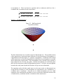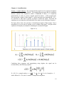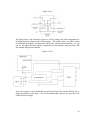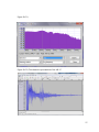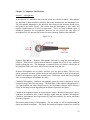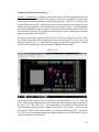
1
Chapter 1: Executive Summary Section 1 – Brief Project Description: The Acoustic Triangulation Device (ATD) is an electronic system designed to detect the location of a sonic event, specifically gunshots or explosions, and relay that location in real time to the user. Its main subsystems include but are not limited to a microphone array, GPS locator, and real time triangulation software. These systems will work together to determine the origin of any sonic event within a predetermined frequency range. This relative location will be translated into GPS coordinates and relayed a desired remote device. As will be shown, the philosophy of use is broad and the device will prove useful in a variety of applications. Each microphone array consists of four microphones in a pyramid configuration. The spacing and relative position of each microphone will be discussed in further detail in Chapter 3: Triangulation Theory. The microphones will be connected to a central timing unit that will measure the exact time that each microphone detects a valid event. The accuracy of the unit highly depends on the speed of our clock and the geometry of the array. Both the geometry of the pyramid and the arrival time of the events will be used by the triangulation software to calculate a unit vector in the direction of the event‟s origin. A second array will simultaneously time the event and the two calculated unit vectors will intersect at the acoustic source. A Global Positioning System (GPS) unit will be present in each array. This will provide the triangulation software with the absolute position of each unit and allow for central reference points in our calculations. These reference points will then be coupled with the relative vectors produced by the microphone array to provide an absolute position of the source. The source location can then be transmitted to the authorities, emergency services, or other remote user enabling them to take appropriate action in a timely manner. The real time triangulation software will act as a central hub for all sensor array and GPS information. The event times for each speaker array will be processed through the triangulation algorithms described in Chapter 6: Software and a unit vector in the direction of the source will be calculated. The three dimensional intersection of the unit vectors from each array will be calculated to provide the source location relative to the sensor location. The software will then use this relative location as well as the absolute location of each array to calculate the absolute coordinates of the source. The source coordinates will be displayed in the user interface along with an alert letting the user know an event has occurred and a map of the event‟s location. User options will include relaying step by step directions to the source, saving the source sound waves in a database for later playback, and transmitting the source coordinates to a remote user. The software will be designed to install and run in a Microsoft Windows environment. The ATD is designed to be scalable. Additions that can be incorporated may include but are not limited to a video surveillance unit that vectors to the source location, a Digital Signal Processing (DSP) unit to analyze and distinguish between types of events, simultaneous multiple shot recognition, and solar charging capabilities. The video 1 surveillance will consist of a linear control system that actuates towards the source GPS location and zooms in to a proper magnification based on the source distance. The DSP will be used as described in Chapter 4: Sound Detection to compare an event to a database of event wavelets and provide information about the source to the user such as gunshot type or signal attenuation. Simultaneous shot recognition would use the DSP to allow the ATD to separate multiple sources from multiple directions and relay all of the source locations simultaneously to the user. Solar power would allow the unit to be rapidly deployed in obscure locations. It would eliminate the need for an infrastructure to run the unit, making it a convenient choice for military applications. It will require further investigation to successfully integrate all of these additions. Section 2 – Motivation: Our combined knowledge of microcontroller programming, signal analysis, and software design proved the ATD to be the perfect project for our group. Our main motivation was to find a project to which we could all contribute equally and stay interested in through the entirety of our Senior Design experience. Additionally we were looking for a project that was applicable to real world events and would prepare us for our real world careers. With crime on the rise as well as recent world events, the ability to accurately detect gunfire has become increasingly important. Our first priority of course is to save lives by giving law enforcement their most advanced tool yet in the apprehension of armed criminals. If the location of a gunshot is known in real time, and the authorities can be notified instantly, the criminal has a greater chance of being caught and is therefore less likely to commit the crime in the first place. We all have vast experience with both firearms and electronics which makes this an exciting endeavor for everyone in the group. Learning more about topics we already love and are knowledgeable about makes this more of a hobby for us than a school project. Being passionate about what we‟re doing will keep us interested, and a high level of interest will yield excellent results in the final product. Passion and interest were important deciding factors for the ATD project. Section 3 – Philosophy of Use: We envision the ATD being used in four main situations including VIP protection, inner city law enforcement, military personnel protection, and civilian property protection. Clearly there are other applications but the ATD will be most effective in these areas. An example of a VIP protection scenario would be a large speech by an important public figure. History has shown these speeches to be among the most vulnerable times for public figures, and with the large numbers of people attending, it‟s easy for a gunman to escape in the crowd. If, once the shot was fired, the gunman‟s exact GPS location and a surveillance video of the area were sent to the secret service for example, the gunman would be apprehended immediately or better yet, knowing this, would never have fired in the first place. 2 Inner city law enforcement would find the ATD useful against gang violence and long distance fire such as Washington DC‟s beltway sniper situation in 2002. In situations like these, often there is no one left to alert the authorities once the crime has been committed. This results in slow response times by the authorities and emergency services and little if any evidence is left on scene by the time they arrive. If however, the ATD was used to alert law enforcement and paramedics, they could be on scene within minutes after the first shot was fired. The faster response time would lead to the apprehension of the criminal and an increased chance of saving the victims life. Military personnel would find the ATD especially useful as they are under fire for much of their career. Knowing the GPS coordinates of an ambush by guerilla fighters, snipers or even tank fire, the soldiers would be able to order an airstrike or mortar attack on the enemy position. Additionally the coordinates could be relayed to a drone to survey the area and send back reconnaissance data increasing our troops‟ survivability and lowering the chance of friendly fire. Owners of civilian properties, or national parks could use the ATD to detect if there is gunfire in an unauthorized location. Owners of hunting grounds would be able to tell if there was out of season hunting, or hunting in restricted or protected areas. The DSP addition would allow the property or park owners to determine if an unauthorized type of weapon was being fired on the premises thus helping with the conservation of wildlife. As you can see the ATD is extremely versatile and benefits everyone, everywhere, every time, real time. Figure 1.3 a) Figure 1.3 b) Figure 1.3 c) Figure 1.3 d) 3 Chapter 2: Requirements and Specifications Section 1 – Requirements: requirements: The ATD must be able to demonstrate the following Range and accuracy: The ATD must be accurate at long distances. The farther away the source is the less accurate the triangulation becomes, yet snipers can easily hit their targets from well outside 1000 meters. In order to be accurate at long distances our signal resolution must have a high signal resolution and in turn a high sample rate. This will require a fast clock. Additionally the farther apart each microphone is the more accurate the ATD will be. This size accuracy trade off will be important to balance. The ATD is intrinsically less accurate than the GPS it uses to determine its own position. This is due to two main factors. First, the GPS satellites surround the “source” which, in our case, is the GPS unit itself. This makes the GPS triangulation calculations simpler and more accurate than the ATD which is at a single location outside of the source. This is discussed in further detail in Ch 3 Triangulation Theory. The second is that the GPS satellites are thousands of kilometers apart, yet the ATD unit‟s satellites (microphones) are within a meter of each other. Cost: The ATD must be low cost in order to be effective. This would allow many ATD units to be spread across large areas such as cities or military encampments at a reasonable price. Additionally singular units should be affordable to private owners who may only need small areas of coverage. A good metric for the affordability of a unit may be its price per cubic foot of coverage. The cost of production will be largely determined by the GPS and Microcontroller. As shown above the ATD is intrinsically less accurate than the GPS and as such the error due to using a less expensive GPS is negligible in comparison to the error in the ATD unit. However we would like to minimize the ATD error and so where we will use an inexpensive GPS, we must use relatively expensive microphones, and a high frequency processor to take samples. The higher sample rate will let us put the microphones closer together while maintaining accuracy. Smaller units will therefore be more expensive. Computing requirements: The ATD must be able to give immediate feedback regarding the location of the source. This means efficient software and a clean easy to use interface. The sources GPS location must be apparent to the user within seconds in order for the source to be eliminated or contained. The computing requirements for this are relatively low however we will need a higher clock frequency on the DSP to produce accurate results. The faster the clock the higher the sample rate thereby creating a more accurate ATD. As stated before this has a direct effect on the price. Additionally the higher the clock rate, the closer together we can place microphones and the smaller we can make the unit as a whole. Portability: The ATD must be portable enough for its philosophy of use. If the ATD is being used as coverage for speeches by important public figures, the unit may have to be taken with them to multiple locations. This would require the unit be relatively light weight, and small enough to pack, perhaps to take on an airplane. 4 If however the unit is being used on the battlefield where it can be carried on armored personnel units it may not need to be as small or as light. In fact, for military applications, it may be desirable to have a larger unit and increase accuracy. In this application though, the unit must be small enough to be mobile as the battlefield is a constantly changing environment. In a situation like Washington DC‟s beltway sniper in 2002 we might want the unit to be small enough to be concealable. Where you would want a criminal like this to know the ATD exists, you wouldn‟t want him to know where they are and therefore be able to avoid or disable the unit. A similar unit could be used to prevent gang violence and unlawful gunfire within city limits. Durability: The ATD must also be durable enough for its philosophy of use. Returning to the speech scenario the unit should be able to survive constant handling and the abuse of travel. Packing and unpacking the unit should not change its dimensions in the slightest way. Any dimensional change in the unit will cause it to be increasingly inaccurate. For the battlefield scenario, the need for durability is apparent. Even in an armored vehicle the unit may be subject to vibration and shock. If the vehicle is jarred or turned over suddenly, the unit should still be able to function. The unit must be water resistant and heat resistant to cope with extreme outdoor environments. This applies to all scenarios where the weather will be unknown including the urban scenario described above. Ease of Use: The ATD must be easy to set up and use. It might seem that a preliminary set up would include leveling the units to the millimeter, aiming them in the correct orientation also to the millimeter, spacing each array to an exact specified distance, calibrating the unit with sensitive equipment, all while in the heat of battle or in the frenzy of a public event. The average user simply isn‟t capable of this, nor should they have to be. The ATD must be able to accurately triangulate an event from any orientation. Each ATD array must be able to be placed an arbitrary distance from each other. The ATD must never need calibration as setup time is critical in many of the scenarios described above. The user interface must be clean and simple. The feedback from the system must not be ambiguous and should have immediate meaning to the user. For example different scenarios require different coordinate systems and this must be apparent upon display. Section 2 – Specifications: The ATD must be capable of determining even coordinates within the following specifications. The ATD must Be under $500 We will accomplish this by minimizing our GPS costs as described above. Additionally we will use a low cost microcontroller and write the software on a free compiler. Chapter 5 7 Section 1 Budget shows that we are well under $500 and this allows for some margin of error as well as extra funding for additional components. Be under 10 lbs We will accomplish this by using light weight composite materials. Furthermore we will minimize the number of sensors and equipment to only what is necessary for the triangulation of the source. Be under 1 cubic meter We will accomplish this by using a microcontroller with a high speed clock. This will provide for increased accuracy with smaller microphone spacing. This is described in further detail in Chapter 3 Triangulation Theory. Be accurate to within 4 meters at a range of 400 meters We will accomplish this by sampling the source wave at a high rate, thus increasing resolution and decreasing error. Each array will have its own independent GPS giving the user the ability to place them anywhere they like (minimum allowable distance is at least 5 meters apart) Be able to be set up in less than 5 minutes We will accomplish this by programming the user interface to startup quickly and letting the arrays be placed at arbitrary distances. Also the arrays can be in any orientation at any height and still provide accurate results as described in Chapter 3 Triangulation Theory. This will allow the user to place the units quickly, anywhere and in any orientation they like. Software should install on any Windows XP or later computer We will accomplish this by programming the software in Microsoft Visual Studio and packaging the install file in a Microsoft Windows executable format using the Visual Studio packaging tool. Triangulate targets at multiple altitudes We will accomplish this as described by the equations shown in detail in Chapter 3 Triangulation Theory. Respond in less than 1 second We will accomplish this by programming a fast interface as well as making sure that the Microcontroller has a high enough transfer rate. Triangulate targets while moving under 20mph We will accomplish this as described by the equations shown in detail in Chapter 3 Triangulation Theory. Work in any orientation We will accomplish this as described by the equations shown in detail in Chapter 3 Triangulation Theory. 6 Figure 1.1 b) 7 Chapter 3: Triangulation/Multilateration Section 1 – 2D Multilateration: There are several different ways to find the location of the source of a sonic event. In our initial attempt to accomplish this task we used mulitilateration. This method needs only one array with at least three microphones for the two dimensional case and at least four microphones for the three dimensional case. Another benefit that the hyperbolic multilateration method has over triangulation is that the array can be any shape. When using the time difference of arrival of a sound wave between two microphones, the possible location of the sound source is a hyperbola as shown in figure 3.1 a. Knowing that the upper microphone heard the sound first, we can eliminate half of the hyperbola. The points along the hyperbola are the only places such that the difference in time for the sound wave to reach the second microphone after having reached the first microphone is the same. As the sound source approaches a point that is equidistant from the two microphones, the hyperbola flattens out. At this point where the source is equidistant from the two microphones, the sound wave will reach the two microphones at the same time and thus a straight line will represent the possible locations of the source. When a third microphone is added there are three different parings of microphones which will produce three different hyperbolas of possible locations based on their respective time differences of arrival. There is only one location where all three hyperbolas intersect, as shown in Figure 3.1 b, and this location is the location of the event source. Figure 3.1 b also demonstrates the fact that the microphones can be at any location. Each pair of microphones will produce a possible location hyperbola regardless of their location with respect to the other microphones in the array, as long as the three microphones are not in a single line. If the microphones are all in a single line there are still two points at which all hyperbolas intersect. Any additional microphones located in the same line beyond the first two will not give any new information. Figure 3.1 – 2D Hyperbolic Multilateration a) hyperbola of possible locations b) intersection of 3 hyperbolas 8 The point that is found after solving all the required equations is the relative location of the sound source with respect to the array. In order to find the exact location a compass is still required. Since we will know the locations of each microphone relative to the GPS unit in the array, the orientation of the array given by the compass will give us the exact coordinates of each microphone. The relative location of the source and the exact locations of the microphones can be used to calculate the exact location of the sound source. The multilateration equations involved in finding the exact location of the source start with the distance/rate/time formula in the same manner as the triangulation equations. The speed of sound, C, is the same formula as above relating to the temperature, T. 𝐶 = 331.3 + .606 × 𝑇 The distance, D, in the distance/rate/time formula now represents the distance from a particular microphone to the sound source. The time, t, now represents the time it takes for the sound wave produced by the sonic event to reach the particular microphone. 𝐷𝐴 = 𝐶 × 𝑡𝐴 The distance can be represented by the distance formula which uses the coordinate location of two points. For the two dimensional case there are three microphones located at points A, B, and C, which each have an x-coordinate and a y-coordinate. The sound source also has an x-coordinate and a y-coordinate that we will call x and y respectively. This gives us three equations. 𝑥 − 𝑥𝐴 𝑥 − 𝑥𝐵 𝑥 − 𝑥𝐶 2 + (𝑦 − 𝑦𝐴 )2 = 𝐶 × 𝑡𝐴 2+ 𝑦−𝑦 2 =𝐶×𝑡 𝐵 𝐵 2 + (𝑦 − 𝑦 )2 = 𝐶 × 𝑡 𝐶 𝐶 Unfortunately since we do not know the exact time the sonic event initially occurs we cannot know the time it takes the sound wave to travel to each individual microphone. Instead since we know the time the sound wave reaches each microphone we can use the difference between the time of the wave‟s arrival at the first microphone and the time of arrival at each other microphone. This difference is equal to the difference between the amount of time it takes the wave to reach each microphone. Solving the equations for t and then subtracting gives us these equations. 1 𝐶 1 𝐶 𝑥 − 𝑥𝐵 2 + 𝑦 − 𝑦𝐵 2 − 𝑥 − 𝑥𝐴 2 + (𝑦 − 𝑦𝐴 )2 = 𝑡𝐵 − 𝑡𝐴 = 𝜏𝐴𝐵 𝑥 − 𝑥𝐶 2 + 𝑦 − 𝑦𝐶 2 − 𝑥 − 𝑥𝐴 2 + (𝑦 − 𝑦𝐴 )2 = 𝑡𝐶 − 𝑡𝐴 = 𝜏𝐴𝐶 Also if we choose an origin for the system at microphone A then we can simplify further. This means that the locations for microphone B and C are relative locations with respect 9 to microphone A. There are then two equations and two unknowns which are the xcoordinate and y-coordinate for the sound source. 1 𝐶 1 𝐶 𝑥 − 𝑥𝐵 ′ 2 + 𝑦 − 𝑦𝐵 ′ 2 − 𝑥 2 + 𝑦 2 = 𝑡𝐵 − 𝑡𝐴 = 𝜏𝐴𝐵 𝑥 − 𝑥𝐶 ′ 2 + 𝑦 − 𝑦𝐶 ′ 2 − 𝑥 2 + 𝑦 2 = 𝑡𝐶 − 𝑡𝐴 = 𝜏𝐴𝐶 Section 2 – 3D Multilateration: Figure 3.2 – Half hyperboloid of possible locations The three dimensional case is similar to the two dimensional case. The possible location of the sound source, based on the time difference of arrival between two microphones, is a hyperboloid as shown in figure 3.2, instead of a hyperbola. To find the exact location of the sound source at least four hyperboloids and therefore four microphones are needed find a single point of intersection. These microphones can be located at any position as long as they are not all in the same plane. If all the microphones are in the same plane there will be two points at which all hyperboloids intersect. As before, any microphones located in the same plane beyond the first three will give no new information. The equations used to find the sound source are the same as the two dimensional case except that the locations of each microphone are represented by an x-coordinate a ycoordinate and a z-coordinate. Also the use of a fourth microphone gives us a third equation to solve and therefore the ability to solve for the three unknowns which are the x-coordinate the y-coordinate and the z-coordinate of the sound source. 10 1 𝐶 1 𝐶 1 𝐶 𝑥 − 𝑥𝐵 ′ 2 + 𝑦 − 𝑦𝐵 ′ 2 + 𝑧 − 𝑧𝐵 ′ 2 − 𝑥 2 + 𝑦 2 + 𝑧 2 = 𝑡𝐵 − 𝑡𝐴 = 𝜏𝐴𝐵 𝑥 − 𝑥𝐶 ′ 2 + 𝑦 − 𝑦𝐶 ′ 2 + 𝑧 − 𝑧𝐶 ′ 2 − 𝑥 2 + 𝑦 2 + 𝑧 2 = 𝑡𝐶 − 𝑡𝐴 = 𝜏𝐴𝐶 𝑥 − 𝑥𝐷 ′ 2 + 𝑦 − 𝑦𝐷 ′ 2 + 𝑧 − 𝑧𝐷 ′ 2 − 𝑥 2 + 𝑦 2 + 𝑧 2 = 𝑡𝐷 − 𝑡𝐴 = 𝜏𝐴𝐷 Section 3 – Error: When using multilateration there are several possible sources of error. The microphones can be too low resolution and cause inaccurate event times, the clock used to find the time difference can be inaccurate, or general noise in the system can give inaccurate readings and therefore cause inaccuracies in the calculation of the sound source location. To reduce the effects of these inaccuracies, estimation methods can be used. These estimation methods use the data from additional microphones and essentially average the resulting solutions to produce a final answer. For the three dimensional multilateration case, only four microphones are needed. We will instead be using eight microphones in a cube shaped array. This will produce additional timing data and allow us to find several possible locations. Since each array of four non coplanar microphones can produce a location for the sound source, we will use each of these possible arrays in our configuration to find a location estimate. The possible arrays include choosing three microphones from one face and one microphone from a different face. Examples of valid arrays would include microphones 1, 2, 3, and 5; microphones 1, 4, 8, and 7; and microphones 5, 8, 7, and 3 as seen in Figure 3.3 a. In total there are 58 valid arrays based on the cube configuration, therefore there are 58 different possible locations for the sound source. In the equations found in chapter 3-1 microphones A, B, C, and D can be replaced with the first, second, third and fourth microphones, respectively, in the chosen subset array. The microphones should be ordered from the first to hear the sonic event to the last to hear the sonic event so that the time difference of arrival values are positive. The solving of these equations then result in an x, y, and z coordinate for a possible location. Iterating through all possible combinations produces 58 estimations of the location of the sound source. The easiest way to estimate the location is to average all of the x-coordinates then all of the y-coordinates then all of the z-coordinates using the following equations. 𝑥𝑎𝑣𝑔 = 𝑥 1 +𝑥 2 +⋯+𝑥 58 58 , 𝑦𝑎𝑣𝑔 = 𝑦 1 +𝑦2 +⋯+𝑦 58 58 , 𝑧𝑎𝑣𝑔 = 𝑧1 +𝑧2 +⋯+𝑧58 58 It turns out that this estimation method is not accurate enough to be within the specifications that we desired. Another method using non-linear least squares regression is a better method for estimating the source location. This method is very difficult to accomplish. After much trial and error we realized that not only was this method not very feasible, it also required the use of faster and more expensive equipment which would have also put us outside our specifications. 11 Figure 3.3 b shows some sample points generated by several array subsets and the average of those points. This point (xavg, yavg, zavg) is the estimated relative location of the sound source with respect to the array. Figure 3.5 a) Cube shaped array 1 b) Estimated source location 2 4 3 5 8 6 7 Section 4 – 2D Triangulation: After having much difficulty with multilateration we decided to derive our own equations using triangulation instead. For two-dimensional triangulation we need two arrays of three microphones each, oriented in an equilateral triangle, to determine the exact location of a sound source. Each array will give us an angle which tells us the direction of the source. Using these two directions and the known distance between the two arrays we can determine the sound source‟s location. If the microphones are close enough together and the sound source is sufficiently far away we can assume the sound wave approaches as a straight line perpendicular to the line originating from the source. We can then find the distance Δx in figure 3.4 below, using the distance/rate/time formula where the distance is Δx, the rate is the speed of sound, C, and the time is the difference between the time of first detection and the time of second detection, tB – tA. ∆𝑥1 = 𝐶 × 𝑡𝐵 − 𝑡𝐴 The speed of sound, C, changes in relation to the temperature of the air. Other factors can affect the speed of sound, such as the barometric pressure and humidity, however 12 these factors are insignificant in comparison to the temperature. The temperature, T, is measured in ˚C. 𝐶 = 331.3 + .606 × 𝑇 Knowing the distance, Δx, and the side of the array, S, we can find the angle θ 1 using trigonometry. Then we can find the angle α1 based on its relationship with θ1 as shown in figure 3.4. 𝜃1 = cos −1 ( ∆𝑥 1 𝑆 ), 𝛼1 = 𝜃1 − 30° These equations will work regardless of the orientation of the array, therefore the times t A and tB will always be the time that the first and second microphones detect a sonic event, respectively. Based on these equations there are two locations that the source could come from, one on each side of the line which connects the first and second microphones. The third microphone tells us that the source came from the opposite side that it is located. There are two equations which can tell us the value of Δy1. The first is based on the speed of sound and the times of the second and third detections of the sonic event. The second equation is based on the triangle made up of Δy1 and the base of the array, and the angle determined by the previous equations. ∆𝑦1 = 𝐶 × 𝑡𝐶 − 𝑡𝐵 , ∆𝑦1 = 𝑆 × cos(180° − 60° − 𝜃1 ) If these two equations are not equal, then there is some error involved in the calculations. This error could be caused by the source being at a location other than ground level. Alternatively the error could be caused by inaccuracies in the time readings. All of the above equations that were used to find the values of the first array, and therefore the angle α1, can also be used to find the values of the second array, and therefore the angle α2. Using the angles α1 and α2 found by the previous equations, we can determine the angles β1, β2, and β3 of the larger triangle formed by the lines connecting the two arrays and the sound source, as shown below in figure 3.1. The relationship between the β angles and the α angles will have to be determined by knowing the orientation of each array with respect to the line that connects the two arrays. This information will be determined using a compass on each array. Based on figure 3.4 below, the case in which both arrays are in the same orientation and their bases are parallel to the line that connects them to each other, the correct equations to use would be the following equations. 𝛽1 = 90° + 𝛼1 , 𝛽2 = 90° − 𝛼2 , 𝛽3 = 180° − (𝛽1 + 𝛽2 ) Then using the Law of Sines we can determine the distance from the first array to the sound source. 13 𝐷= sin 𝛽2 × 𝐿 sin 𝛽3 In order to find the exact location, we then need to know the exact location of each array. This information is given to us by the GPS. Since the size of each array is small in comparison to the distance from the sound source to the arrays, the GPS can be located at any point inside the array and still give a good enough approximation of the array‟s location. This means that we can say that each microphone is at approximately the same location as the GPS unit. The coordinates for the sound source are found by adding the vertical portion of the distance to the vertical coordinate of the GPS and the horizontal portion of the distance to the horizontal coordinate of the GPS for the first array. The vertical and horizontal directions will have to be normalized to North/South and East/West directions to find the proper coordinates. This will be accomplished by using the compass values for each array and will adjust the α and β angles accordingly. The equations for finding the vertical and horizontal portions of the distance to the sound source based on figure 3.4 below, the case in which the positive vertical direction is North and the positive horizontal direction is East, are the following. 𝐷𝑣𝑒𝑟𝑡 = 𝐷 × sin(180° − 𝛽1 ) , 𝐷𝑜𝑟𝑖𝑧 = 𝐷 × cos(180° − 𝛽1 ) Combining these equations we can get a single equation for the angle that each array produces with only the variables tA, tB, the temperature, T, and α. 𝛼1 = cos−1 (331.3+ .606×𝑇)×(𝑡 𝐵 1 −𝑡 𝐴 1 ) 𝑆 − 30°, 𝛼2 = cos −1 (331.3+ .606×𝑇)×(𝑡 𝐵 2 −𝑡 𝐴 2 ) 𝑆 − 30° We can also combine the previous equations to get a single equation for the distance between the sound source and the first array, D, with only the variables α1, α2, the distance between the two arrays, L, and D. 𝐷= sin(90° − 𝛼2 ) × 𝐿 sin(180° − (90° + 𝛼1 ) + (90° − 𝛼2 ) ) 14 Figure 3.4 – 2D Triangulation β3 D α1 α2 β1 S Δx1 β2 S θ1 L θ2 S Δy1 S S S Δx2 Section 5 – 3D Triangulation: For three dimensional triangulation the equations are similar to the two dimensional case. When in three dimensions there are two angles represented by each array instead of just one. Each array will then consist of an equilateral triangular pyramid. The two directions produced by these arrays will again allow us to determine the exact location of the sonic event. In the three dimensional triangulation case we approximate the sound wave as a plane instead of a line. Also two perspectives are needed to get the two angles that make up the 15 direction. Figure 3.5 a below shows a side view which is rotated 30˚ above being parallel with the ground. This means that the side view is perpendicular to the plane made by the front face that is shown, and that the dot in the center represents the rear microphone that would be recessed into the page. The top view is perpendicular to the plane that is the ground and the dot in the center represents the top microphone which would be protruding out of the page. This top view is rotated from the side view such that the line connecting the two lower microphones is fixed and the upper microphone is rotated down and out of the page by 60˚. The same formula is then used as in the two dimensional case to determine the length Δx, this formula works for both the side view and the top view. ∆𝑥1 = 𝐶 × (𝑡𝐵 − 𝑡𝐴 ) The speed of sound, C, is different in the three dimensional case. In each view only a portion of the vector that represents the speed of sound is traveling in the same direction as the vector that points along Δx. This portion is dependent on the angle of the opposing viewpoint. In this way the two separate equations are solved simultaneously which results in finding the correct direction towards the sonic event. 𝐶𝑆𝐼𝐷𝐸 = 𝐶 × sin 𝛼2 , 𝐶𝑇𝑂𝑃 = 𝐶 × sin 𝛼1 Knowing the distance, Δx, and the side of the array, S, we can find the angle θ 1 in the same way as two dimensional triangulation. Then we can find the angle α1 based on its relationship with θ1 as shown in figure 3.2 below. 𝜃1 = cos−1 ( ∆𝑥 1 𝑆 ), 𝛼1 = 𝜃1 − 30° These equations again should work regardless of the orientation of the array. There are still two locations that the source could come from, one on each side of the line which connects the first and second microphones. The third microphone again tells us that the source came from the opposite side that it is located. The top view and the side both use the same equations with the exception of the value for the speed of sound. This allows for the simultaneous solving of the two equations which gives the values for the angle α1 and the angle α2. The angle α2 which is based on the top view must be normalized based on the reading from the compass. The angle α1 which is based on the side view must be normalized to find the vertical angle with respect to the ground. These angles for each array can then be used to find a distance and direction and therefore an exact location, in a similar way as in the two dimensional case. This exact location however will also take into account the elevation of the source of the sonic event. 16 Figure 3.5 – 3D Triangulation a) Side view – single array b) Top view – single array α1 S Δx1 θ1 α2 S S Δx2 S θ2 c) View with both arrays 17 Chapter 4: Sound Detection Section 1 – Signal Analysis: We reconstructed the signal out of a separate microphone attached to the computer using MatLab. The sampling theorem states that if a continuous function contains only frequencies within a bandwidth, B Hertz, it is completely determined by its value at a series of points spaced less than 1 / (2*B) seconds apart. This means that a signal of finite length T, can be restricted to the bandwidth B = f max – fmin, therefore we only need to specify An and Bn to define the signal. From this, the sampling rate now depends on the bandwidth of the signal, not the maximum frequency. The figure below shows the spectrum of a band-limited signal of finite length. This is important for us to use since a gunshot is not an infinite long signal. Using the below equations will simplify our analysis in obtaining the reconstructed signal. Figure 4.1 a) Combining these equations and manipulating using algebra, the signal can be reconstructed by the following equation. 𝐹𝑠 > 2𝐵, 𝑋𝑖 = 𝑠𝑎𝑚𝑝𝑙𝑒 𝑣𝑎𝑙𝑢𝑒𝑠, 𝑡𝑖 = (𝑖×𝑇) 1 𝑘 𝑠 𝑇 , 𝑇 = 𝐹 , ∆𝑡 = 𝑘 , 𝐾 = # 𝑜𝑓 𝑠𝑎𝑚𝑝𝑙𝑒𝑠 − 1 And it follows K > 2N, with N = number of amplitudes and phases. 18 Shown below is a figure of signal reconstruction from a series of sampled values using the sinc function from above to do the reconstruction. Figure 4.1 b) The reason why we want to reconstruct the signal out of the microphones is that we want to obtain the max amplitude; max frequency, min amplitude, and min frequency that come out of the band pass filters. MatLab will be programmed to do these tasks. Also, with the reconstructed signal, we can then proceed to use more signal analysis in order to distinguish of which type of event has passed through our band pass filters. Before we begin to explain the method we will be using for our type of gun detection, it is important that we first explain what a sound wave actually is. A sound wave is a traveling wave with an oscillation of pressure through air of frequencies within range and level of hearing. The speed of sound depends on the medium, temperature, and elevation of which the wave is traveling, not by the frequency or amplitude of the sound. In air, the speed of sound at sea level is approximately 343 m/s. Sound propagates through air as a longitudinal wave. Longitudinal sound waves are waves of alternating pressure from the equilibrium pressure, which cause regions of reduction in volume and density. Type of gun detection: In order to tell which type of gun was fired, we must be able to compare the event gunshot‟s sound wave with a database of gunshots that we have previously recorded and stored. We are not trying to reconstruct the original gunshot characteristics; we would just be comparing the event that we have received from our band pass filters with our database and then deciding which type of database signal best matches the event. In order to do this, we must have a large knowledge in the understanding of how the Fourier transform and wavelets transform works. The Fourier Transform: The Fourier transform is often called the frequency domain representation of the original function. The frequency domain representation is used to show which frequencies are present in the original function. The Fourier transform can separate low and high frequency information of a signal, and is mainly used for processing signals that are composed of sine and cosine signals. From our vast 19 knowledge and experience using the Fourier transform, it would be extremely nice if this could be implemented in the design of the ATD. The equation for the Fourier transform is as follows: The figure below is an example of a Fourier transform (ii) done on cosine signal (i) with thirty samples, sampled at ten samples per period. Figure 4.1 c) i) ii) Unfortunately, after further research, the problem with the Fourier transform being used in our project is that it can tell what frequencies are in the original signal, but it does not tell at what time instances the frequencies occurred. Since our recordings of our gunshots are non stationary, meaning they do not repeat, the Fourier transform is not a good method in order to compare our event gunshots with recorded gunshots. Because of this, the wavelet transform must be the method used for our non stationary recordings. Section 2 – Wavelet Analysis: Wavelets are localized waves whose energy is concentrated in time and space and are perfect for the analysis of transient signals. A wavelet transform is the representation of functions using wavelets. Wavelets are scaled into copies of daughter wavelets over a finite length non periodic waveform referred to as the mother wavelet. Wavelets are better used than Fourier analysis for our project, because they are used for non periodic waveforms, and they are also ideal at representing sharp peaked functions, such as the characteristic of a gunshot. 20 Figure 4.2 – Demonstration of a (A) wave and a (B) wavelet (A) (B) The type of wavelet transformation that we are interested in using for the ATD is the Discrete Wavelet Transform. The DWT is easy to implement and has a fast computation time with minimum resources required. In order to get the DWT, the use of high pass and low pass filtering is used on the signal. The figure below is of the wavelet decomposition tree, X(n) is the signal, Ho are the High Pass filters, Go are the Low Pass filters, D(n) are the detail information, A(n) is the coarse approximations associated with the scaling function. As you can see from this figure, down sampling is used, which means that only one out of two data is used in this process. At each level in the above figure, the signal is decomposed into low and high frequencies. The input signal must be a multiple of 2^n, with n equal to the number of levels. Figure 4.2-2 Down sampling is used in DWT because for every time you filter, you are incrementing by a large amount of data, so it is necessary for down sampling to occur. It should also be noticed that when half of the frequencies of the signal are removed, half the samples can be discarded according to Nyquist‟s rule. After this entire process is completed, there will be numerous signals that represent the same signal, but each signal will correspond to a specific frequency range. This process can be repeated multiple times, and the number of times it is repeated corresponds to what the application calls for. For our design, we will have to test this to see how many processes we need for our analysis. There are many different types of wavelet shapes to choose from. Using Matlab we have come across the Daubechies wavelet. This wavelet is most similar in shape to that of a gunshot. The following figure is an example of the Daubechies wavelet in Matlab. 21 The figure below shows a Daubechies wavelet in Matlab with a decomposition level of four. As you can see from the figure, it shows the decomposition of the low and high pass filter. This wavelet will be used in our project to divide our time signals into different scaled components. After each component is scaled, we will be studying each component. This data compression technique will then allow us to compare our event gunshots, with our database of stored characteristics. Figure 4.2-3 Figure 4.2-4 22 The above figure shows a Daubechies wavelet in Matlab with a decomposition level of six. As you compare the difference of decomposition levels, you can notice the wavelet functions difference. The higher the decomposition level, the more compressed the signal becomes. The Daubechies family can either be orthogonal or biorthogonal. Equations for the discrete wavelet transform: In the above equation is the mother wavelet. This mother wavelet is a representation of a function in time with a finite energy. This mother wavelet also has a fast decay time. The discrete wavelet transform can be computed using an extremely quick pyramidal algorithm. This pyramidal algorithm allows the signal to be analyzed in different octave frequency bands and it allows different resolutions by decomposing the signal in coarse approximations and detail information. This decomposition as mentioned above is done by using the high pass and low pass filtering of the time domain signal. Where Y[k] are the outputs of the high and low pass filters after the down sampling of a factor of two. The wavelet coefficients represent the energy of the signal in the time and frequency. These coefficients can be represented by using different techniques such as by taking the ratios of the mean values between adjacent sub bands in order to provide information on the frequency distribution. Other techniques such as by taking the mean value of the coefficients in each sub band can also provide information on the frequency distribution. In order to get the change in frequency distribution, we must take the standard deviation in each sub band. For our design purposes, we will be comparing the coefficients of the wavelet transforms. To make certain that all of our wavelet transforms are comparable to each other, all of our scales of our wavelet functions must be normalized to have unit energy. The equation we will be implementing to do the normalization is as follows: Then, after normalization each scale s has 23 with N being the number of points. By using the convolution formula, normalization of our functions to have unit energy can be done by: Since in our design we have chosen to use the Daubechies wavelet function, which is an orthogonal wavelet function reconstruction of the original time signal can be determined using deconvolution. The very first step in process of different type of gunshot recognition by using the discrete wavelet transform will be to take our recordings of the various types of guns that we have shot, eliminate all noises that do not pertain to the exact gunshot, and then to normalize the gunshot signatures. The reason that we will be normalizing these recordings is so that the volume of each type of gunshot does not affect our results. After we do the normalizing process, we will then proceed to do the discrete wavelet transform to each of the gunshot recordings. The next step will then be to take each of the gunshot recordings, and get the average of the coefficients. We will then being the storing process on these discrete wavelet transforms and coefficients into a database in the Arduino Mega microcontroller. After the storing process is complete, we will then be able to take the gunshot events, and do the process in order to normalize them in real time. After we have the normalized signal, the discrete wavelet transform will be done on the signal. We will be first taking the input signal of the gunshot events out of the external microphone and then we will send them to MatLab to normalize them. The next process will be to store these events into a database in the microcontroller. After the storing process is complete, we will then proceed and compare the event gunshots with our database of stored recordings in the computer. After the gunshot comparison of the coefficients and signals, we will then use our tolerance algorithm to output the best match of the type of gun that was used from the gunshot event. Section 3 – Amplifier Design: For our prototype, we decided to purchase Breakout Boards for our Electret microphones. The reason why we decided to use these in our design is that they were fairly cheap, and it amplifies our signals coming out of the microphones by one hundred. The figures below are of our Electret microphones set up with the Breakout Board. These are the actual units that will be transferring the sound wave into electric signals. After these signals are created, we can then take these signals and send to them to a filter, and then finally, they can be sent to our Arduino microcontroller. The Arduino microcontroller can then analyze these signals and determine the times of arrival using 24 the microcontroller‟s clock, from when the sound waves approach our array of microphones. The amplification of one hundred from the Breakout Boards should be enough for our microcontroller to be able to pick up a gunshot from a reasonable distance. If the gunshots from distances in our specifications are not received out of the Breakout Board, more amplification will be needed. From the knowledge and experience we have in amplifiers, this will not be a difficult task to solve. Figure 4.3-1) The figure below is a schematic of the Breakout Board. U1 in this figure is an OPA344 Operation Amplifier. This Breakout Board has an operating voltage ranging from 2.7V up to 5.5V. This is perfect for our design, and we will be using the Arduino microcontroller to power these units. The OPA344 is a series rail to rail CMOS operational amplifier designed for precision low power applications. It operates in a temperature range from -55 to 125 degrees Celsius. This operational amplifier has a voltage output swing from rail of 1mV. Figure 4.3-2) 25 Section 4 - Filtering: A gunshot‟s maximum sound level for a typical rifle is in the 130 Hz to 3 kHz Frequency range. The frequency range of an adult male voice is in the frequency range of 85 Hz to 155 Hz, and for an adult female 165 Hz to 255 Hz. Because of this, for our design purpose, we decided to use a band pass filter with a pass band frequency range of 300 Hz to 3 KHz. If we decide not to distinguish between types of gunshots and other sounds, analyzing the signals is unnecessary, and we would just be focusing on triggering when an event happens in the pass band range and then sending those signals from the microphones to the clock. However, if we do decide to distinguish between the different types of sounds, it would require the use of in depth signal analysis. There are many different types of band pass filters. One of the main types that we decided to do research on is the Butterworth Band Pass filter. The reason why we chose to do research on the Butterworth approach is as follows: 1) We have the most experience using them 2) Good frequency roll off 3) No ripples in either pass or stop bands The figure below is of a typical Butterworth band pass filter magnitude response. This is a fifth order Butterworth filter response with the Low pass cutoff frequency at 9 rad/s and High Pass of 0.1 rad/s. The red and pink show the Magnitude response. Phase delay is the green curve, and group delay is the cyan curve response. Figure 4.3-3) 26 After doing more research into band pass filters, we came across an approach that we think is best suited for our design. Since we are going to have to build a filter for each microphone, we will be building up to eight filters. We want each filter to be as close to an exact match as possible, and be as simple as possible to build. The filter design that we will be implementing is as follows. The figure below is of a second order band pass multi-loop filter with no positive feedback. In the figure, V1 corresponds to the microphone. The values for the capacitors and resistors were computed by using a design process with the Center frequency at 1350 Hz, Quality Factor of 0.5, and Mid Band Gain of 0.4. For our band pass filter we will be using the LM 358 operational amplifier. The design process for the values of the resistors and capacitors are as follows: Figure 4.3-4) Second Order Band Pass Multi Loop filter with no positive feedback With Capacitors equal to 0.1 µF, and Wo in radians per second: The figure below shows the typical response of a band pass filter. For our design, f1 and f2 corresponds to 300 Hz and 3000 Hz respectively. The 3 dB bandwidth for our design therefore is equal to the difference between these frequencies (2700 Hz). If we do not get an accurate measure using this band pass design, we will have the freedom in our testing phase to be able to easily adjust the bandwidth by re computing the values for the resistors and capacitors to meet our specifications. 27 Figure 4.3-5) R4 Q Wo * C1 * H BP R5 R6 2*Q Wo * C1 Q Wo * C1 * (2Q 2 H BP ) H BP 2Q 2 The figures below are simulations of our designed filter using the Multisim 2001 program. Figure (A) was simulated with an input voltage of 1V at 200 Hz. As you can see from this figure, the output voltage is extremely low, exactly how we need it to be since it is not in our pass band range. Figure (B) is a simulation with an input voltage of 1V at 1 KHz. As you can see from this figure, the voltage is high since it is in our pass band region. Below is the magnitude and phase response plot for our designed band pass filter. Figure 4.3-6) (A) (B) 28 Below is a magnitude plot of designed band pass filter. Figure 4.3-7) Below is a phase plot of our designed band pass filter Figure 4.3-8) The reason for using the LM 358 in our band pass filter for the ATD is that it is a single supply operating voltage amplifier. Single supply operating voltage is important in our design, because with this we do not need to worry about the negative voltage required to operate the operational amplifier. Since we will be powering all the band pass filters from our Arduino Mega microcontroller, it will make our prototype easier to build. The single supply voltage range for the LM 358 is 3V to 32 V, which is excellent for our prototype since the Arduino microcontroller has an output power supply of 3V and 5V. The figure below is of the connection diagram of the LM 358 chip. The LM 358 contains two operational amplifiers. For our design, we will require up to four LM 358 chips. Using this connection diagram, we can then proceed to design our wiring schematic for the microphones and band pass filters. 29 Figure 4.3-9) The figure below is the schematic of how we will be wiring each of the components for the signal detection scheme of the ATD prototype. This scheme is how we will be wiring an individual microphone and band pass filter to the Arduino Microcontroller. As you can see, the signal detection scheme is composed of a microphone, band pass filter, and the Arduino Mega microcontroller. Figure 4.3-10) From our research, we have found that it would most likely be the easiest and best way to design and build our own filters. We also determined that a passive low pass filter was sufficient for our design. 30 Chapter 4b: Gunshot Theory Section 1 – Sound detection overview: There are many different types of guns, however; the most conventional use an explosive charge to propel the bullet out of the barrel. The sound that comes out of the barrel travels in all directions, but the majority of the acoustic energy travels in the direction that the barrel is pointed. The shock wave that is emitted is called the muzzle blast, and this is what the ATD will be detecting and using to locate the origin of the blast. For our Sound Detection chapter, we were required to go out and shoot different types of guns. This was the fun part of our design project. To the right are pictures of our group and Louis shooting the AR-15 assault rifle. We would like to give a special thanks to Louis Schieferdecker (top) for supplying us with the firearms and ammunition that we used to record our data of the sound waves for all the firearms. We also would like to give a special thanks to Helen and Cliff Johnson for allowing us to use their property in Leesburg, Florida to go out and shoot these firearms. As you can see in the pictures, the weather outside was not ideal. However, with limited time we had to obtain our data, so a little rain did not ruin our plans. In order to obtain the sound waves, one member of our group sat inside a car so the rain would not ruin our laptop, and recorded the sound waves of the guns using the microphones we purchased. The software we used to gather our data is Audacity. We recorded our sound waves using an audio sampling rate of 44 KHz, and with a 16 bit audio sample size Initially, we thought that the rain might affect our readings in a negative way. We first believed that the rain would cause interference in our sound waves and that we would be unable to distinguish the noise apart from the actual gunshots. We also believed that since we were taking our recordings from inside a car, and the microphone being inside the car, that possibly we would have interference in our data due to sound reverberation from the walls of the car. Fortunately for us, these factors did not affect our data, however since we were recording our gunshots from a short distance (5 meters) clipping of the sound waves were obtained because of this. 31 After receiving the sound wave from Audacity, we obtained the Bode Plot of each individual sound wave using the built in Plot Spectrum tool provided in the Audacity software. We then used Audacity to convert the raw sound wave into a .Wav file, in order for Matlab to be able to read the data. Below is the data that we have obtained from our gunshot recordings. Section 2 – Sound Wave Analysis: 45 caliber: The figure below is the waveform of the 45 caliber round. This figure is a visual representation of our recorded sound wave using the Matlab „dis‟ function in DSP tools library. This visualization is the equivalent to what a digital oscilloscope would show. Notice, as you can see in the wave, at around 0.012 seconds there is a small sharp fall, followed by small slight sharp rise. This is the representation of the bullet noise ground reflection of our recorded gunshot. As you can see, right after the bullet noise ground reflection, the signal jumps extremely high. This is the visual representation of the gunshots muzzle blast. This muzzle blast is what our ATD prototype will be detecting from the 45 caliber round Figure 4b-1) 32 Spectrum of the 45 caliber: The figure below is of the frequency spectrum of the 45 caliber round. This figure is a visual representation of the frequency spectrum of our recorded sound wave using the Matlab „spec‟ function in DSP tools library provided by Dr. Kasparis. This program calculates the Fast Fourier Transform over the entire signal. As you can see from this figure, the frequency axis has been normalized. Notice from this figure, at around 0 normalized frequencies, the magnitude is max at around 9. At around 0.01 normalized Figure 4b-2) frequencies the magnitude is around 3.5 magnitude. At a normalized frequency of around 0.03, as you can see from the plot, the magnitude is approximately 3.7. These characteristics in our plots are extremely important, because we will be comparing these characteristics of each gunshot recording to an event gunshot in order to best compare which type of gunshot has been fired. 33 Bode Plot of 45 caliber: Below is a figure of the Bode Plot of the 45 caliber round. This figure is a visual representation of the 45 caliber sound wave‟s Bode Plot using the Audacity software. As you can see in the Bode Plot figure, the peak frequency is at 1249 Hertz, and its magnitude at this specific frequency is -2 dB. Also, it is to be noted from this figure that the max amplitudes of the of the 45 caliber sound wave occur in the frequency range of approximately 500 Hertz to around 1.5 KHz. This frequency range must be noted, and it must be compared to all other types of gunshot characteristics. This frequency range of the max amplitudes will most likely be different for all other types of guns. Figure 4b-3) Figure 4b-4) Time domain representation of the 45 caliber round. 34 .223 caliber (AR 15): The figure below is the waveform of the .223 caliber round. This figure is a visual representation of our recorded sound wave using the Matlab „dis‟ function in DSP tools library. This visualization is the equivalent to what a digital oscilloscope would show of the .223 caliber wave. Notice, as you can see from this figure at approximately three milliseconds, there is a sharp fall and then following, a slight rise of the waveform. This characteristic of the waveform is the representation of the .223 caliber bullet noise ground reflection of our recorded gunshot. As you can see, right after the bullet noise ground reflection, the signal increases in size, and begins to attenuate. This is the visual representation of the AR 15 gunshots muzzle blast. This attenuation in the AR 15‟s muzzle blast is not as high as the other gunshot characteristics. This muzzle blast is what our ATD prototype will be detecting from the .223 caliber round. As you can notice, from the above figure of the 45 caliber round‟s sound wave and that of the .223 caliber round, the sound waves are completely different. This will be an important characteristic in event discrimination. Figure 4b-5) Spectrum of the .223 caliber: The figure below is of the frequency spectrum of the .223 caliber round. This figure is a visual representation of the frequency spectrum of our recorded sound wave using the 35 Matlab „spec‟ function in DSP tools library. Notice from this figure, at around 0.01 normalized frequencies, the magnitude is max at around 4.6. At around 0.02 normalized frequencies the magnitude is around 1.4 magnitude. At around 0.3 normalized frequency, as you can see from the plot, the magnitude was approximately 1. These characteristics of the .223 caliber in our plots are extremely important, because we will be comparing these characteristics of each gunshot recording to an event gunshot in order to best compare which type of gunshot has been fired. Figure 4b-6) Below is a figure of the Bode Plot of the .223 caliber round. This figure is a visual representation of the .223 caliber sound wave‟s Bode Plot using the Audacity software. As you can see in the Bode Plot figure, the peak frequency is at 630 Hertz, and its magnitude at this specific frequency is -3 dB. Also, it is to be noted from this figure that the max amplitudes of the of the .223 caliber sound wave occur in the frequency range of approximately 350 Hertz to around 1 KHz. Bode Plot of .223 caliber: 36 Figure 4b-7) Figure 4b-8) Time domain representation of the .223 caliber round. 37 9 mm Kel-Tec PF-9: Spectrum of the 9mm (Kel Tec): The figure below is the waveform of the 9 mm caliber round of the Kel-Tec PF-9. This figure is a visual representation of our recorded sound wave using the Matlab „dis‟ function in DSP tools library. Notice, as you can see in the wave, at around 0.005 seconds there is a small sharp fall, followed by small slight sharp rise. This is the representation of the Kel-Tec‟s bullet noise ground reflection of our recorded gunshot. As you can see, right after the bullet noise ground reflection, the signal jumps extremely high. This is the visual representation of the gunshots muzzle blast. This muzzle blast is what our ATD prototype will be detecting from the Kel-Tec 9 mm caliber round. Figure 4b-9) The figure below is of the frequency spectrum of the 9 mm caliber round. This figure is a visual representation of the frequency spectrum of our recorded sound wave using the Matlab „spec‟ function in DSP tools library. As you can see from this figure, the frequency axis has been normalized. Notice from this figure, at around 0 normalized 38 frequencies, the magnitude is max at around 7. At around 0.01 normalized frequencies the magnitude is around 1.6 magnitude. At around 0.03 normalized frequency, as you can see from the plot, the magnitude was approximately 0.733. Figure 4b-10) Bode Plot of 9 mm (Kel Tec): Below is a figure of the Bode Plot of the 9 mm Kel-Tec. This figure is a visual representation of the 9 mm Kel-Tec‟s sound wave‟s Bode Plot using the Audacity software. As you can see in the Bode Plot figure, the peak frequency is at 1285 Hertz, and its magnitude at this specific frequency is -5 dB. Also, it is to be noted from this figure that the max amplitudes of the of the 9mm Kel-Tec‟s sound wave occur in the frequency range of approximately 500 Hertz to around 1 KHz. 39 Figure 4b-1l) Figure 4b-12) Time domain representation of the Kel-Tec PF-9 9 mm (Beretta): The figure below is the waveform of the 9 mm Berretta round. This figure is a visual representation of our recorded sound wave using the Matlab „dis‟ function in DSP tools library. Notice, as you can see in the wave, at around 0.004 seconds there is a sharp V shape that looks similar to a razor tooth. This is the representation of the 9 mm Beretta‟s 40 Figure 4b-13) bullet noise ground reflection of our recorded gunshot. As you can see, right after the bullet noise ground reflection, the signal increases, and attenuates extremely high. This is the visual representation of the 9 mm Beretta‟s gunshot muzzle blast. This muzzle blast is what our ATD prototype will be detecting from the 9 mm Berretta round. Spectrum of the 9 mm Beretta: The figure below is of the frequency spectrum of the 9mm Beretta caliber round. This figure is a visual representation of the frequency spectrum of our recorded sound wave using the Matlab „spec‟ function in DSP tools library. Notice from this figure, at around 0 normalized frequencies, the magnitude is at around 0.9. At around 0.01 normalized frequencies the magnitude is around 1 magnitude. Also, from the plot at around 0.03 normalized frequency, as you can see from the figure, the magnitude is max at approximately 3.5. 41 Figure 4b-14) 9 mm Beretta Bode Plot: Below is a figure of the Bode Plot of the 9 mm Beretta round. This figure is a visual representation of the 45 caliber sound wave‟s Bode Plot using the Audacity software. As you can see in the Bode Plot figure, the peak frequency is at 1249 Hertz, and its magnitude at this specific frequency is -2 dB. Also, it is to be noted from this figure that the max amplitudes of the of the 9 mm Beretta‟s sound wave occur in the frequency range of approximately 350 Hertz to around 1.1 KHz. This frequency range must be noted, and it must be compared to all other types of gunshot characteristics. 42 Figure 4b-15) Figure 4b-16) Time domain representation of the 9mm Beretta Below is the time domain representation of the 9mm Beretta. So far, we can tell just by the data that we have recovered from the above firearms, that every type of gun has its own distinguishable characteristics. The frequency range of the sound waves, max magnitudes, and attenuation factors are all types of characteristics that our data varies from. Below is more data that we have gathered for further investigation into the different types of firearms. 43 22 caliber: The figure below is the waveform of the 22 caliber round. This figure is a visual representation of our recorded sound wave using the Matlab „dis‟ function in DSP tools library. Notice, as you can see in the wave, at around 5 milliseconds there is a small sharp fall, followed by small slight sharp rise. This is the representation of the bullet noise ground reflection of our recorded gunshot from the 22 caliber. As you can see, right after the bullet noise ground reflection, the signal jumps extremely high, showing the representation of the gunshots muzzle blast. This characteristic of the 22 caliber round‟s muzzle blast is the signal that the ATD will be detecting and analyzing to distinguish itself from other types of sound. Figure 4b-17) 44 Spectrum of the 22 caliber: The figure below is of the frequency spectrum of the 22 caliber round. This figure is a visual representation of the frequency spectrum of our recorded sound wave using the Matlab „spec‟ function in DSP tools library. As you can see from this figure, the frequency axis has been normalized. Notice from this figure, at around 0 normalized frequencies, the magnitude is max at around 6. At around 0.025 normalized frequencies the magnitude then has another spike maximum magnitude of around 2. At around 0.03 normalized frequency, as you can see from the plot, the magnitude was minimum of approximately 0.2. These characteristics in our plots are extremely important, because we will be comparing these characteristics of each gunshot recording to an event gunshot in order to best compare which type of gunshot has been fired. So far, out of all of the data that we have received, the data for the 22 is the weakest. This spectrum signal of the 22 is extremely small compared to that of all the other guns. The reason for this is because the 22 is a very small round, and while we were firing it, it was definitely not nearly as loud as all the other guns. Figure 4b-18) Bode Plot of the 22: Below is a figure of the Bode Plot of the 22 caliber. This figure is a visual representation of the 22 caliber sound wave‟s Bode Plot using the Audacity software. As you can see in the Bode Plot figure, the peak frequency is at 1197 Hertz, and its magnitude at this specific frequency is -4 dB. Also, it is to be noted from this figure that the max amplitudes of the of the 22 calibers‟ sound wave occur in the frequency range of 45 approximately 600 Hertz to around 1 KHz. This frequency range must be noted, and it must be compared to all other types of gunshot characteristics. Figure 4b-19) Figure 4b-20) Visual representation of the 22 caliber‟s time domain spectrum. 46 38 Blackhawk: The figure below is the waveform of the 38 caliber round. This figure is a visual representation of our recorded sound wave using the Matlab „dis‟ function in DSP tools library. This visualization is the equivalent to what a digital oscilloscope would show. As you can see from the wave in this plot, at around 0.004 seconds there is a sharp fall, followed by a jump in the wave. This is the representation of the bullet noise ground reflection of our recorded gunshot. As you can see, right after the bullet noise ground reflection, the signal then jumps extremely high. This is the visual representation of the 38 calibers gunshots muzzle blast. This muzzle blast is what our ATD prototype will be detecting from the 38 caliber round. From this figure, and comparing with the sound waves, the slope of the fall in the representation of the bullet noise ground reflection is not as steep as the other figures. As you can tell from the figure, the gaps between the Figure 4b-21) signal of the muzzle blast can be noted as wider apart that that of the other gunshot characteristics of the other types of guns. 47 Spectrum of the 38: The figure below is of the frequency spectrum of the 38 caliber round. This figure is a visual representation of the frequency spectrum of our recorded sound wave using the Matlab „spec‟ function in DSP tools library. As you can see from this figure, the frequency axis has been normalized. At around 0 normalized frequencies, the magnitude is around 0.25. At around 0.01 normalized frequencies the magnitude is around 0.7 magnitude. At around 0.027 normalized frequency, as you can see from the plot, the magnitude was maximum and approximately 1.5.As the frequency increases after .005 the signals magnitude begins to decrease. These characteristics in our plots are extremely important, because we will be comparing these characteristics of each gunshot recording to an event gunshot in order to best compare which type of gunshot has been fired. Figure 4b-22) Bode Plot of 38 caliber: Below is a figure of the Bode Plot of the 38 caliber. This figure is a visual representation of the 38 caliber sound wave‟s Bode Plot using the Audacity software. As you can see in the Bode Plot figure, the peak frequency is at 1187 Hertz, and its magnitude at this specific frequency is -6 dB. This peak frequency is very close to the value of the peak frequency of the 22 caliber. Also, it is to be noted from this figure that the max amplitudes of the of the 38 calibers‟ sound wave occur in the frequency range of approximately 600 Hertz to around 1 KHz. This is also extremely similar to that of the 22 caliber characteristics. From observing this data, we believe that it will be a very 48 difficult task for us to determine between the 38 caliber and the 22 caliber. Maybe there is some way with the ratio of coefficients using the wavelet transform that we will be able to distinguish from extremely close data. Figure 4b-23) Figure 4b-24) Time domain representation of the 22 caliber round. 44 Magnum: The figure below is the waveform of the 44 Magnum round. This figure is a visual representation of our recorded sound wave using the Matlab „dis‟ function in DSP tools library. Notice, as you can see in the wave, at around 0.015 seconds there is a small sharp fall, followed by small slight sharp rise. This is the representation of the bullet noise ground reflection of our recorded gunshot of the 44 Magnum. This bullet noise 49 ground reflection is much attenuated. As you can see, right after the bullet noise ground reflection, the signal jumps extremely high. This is the visual representation of the gunshots muzzle blast. This muzzle blast is what our ATD prototype will be detecting, and comparing the coefficients from the 44 Magnum round to that of other types of events. Figure 4b-25) Spectrum of 44 Magnum: The figure below is of the frequency spectrum of the 44 Magnum round. This figure is a visual representation of the frequency spectrum of our recorded sound wave using the Matlab „spec‟ function in DSP tools library. Notice from this figure, at around 0 normalized frequencies, the magnitude is at around 2.6. At around 0.015 normalized frequencies the magnitude is around 2.4 magnitude. At around 0.0266 normalized frequency, as you can see from the plot, the magnitude is maximum and is approximately 4.47. Higher normalized frequencies than .04 begin to decrease in the plot, and become minimum of approximately 0 magnitude at around 0.15 normalized frequency. These are the most important characteristics of the spectrum of the 44 Magnum. 50 Figure 4b-26) Bode of 44 Magnum: Below is a figure of the Bode Plot of the 44 Magnum round. This figure is a visual representation of the 44 Magnum sound wave‟s Bode Plot using the Audacity software. As you can see in the Bode Plot figure, the peak frequency is at 1148 Hertz, and its magnitude at this specific frequency is -3 dB. Also, it is to be noted from this figure that the max amplitudes of the of the 44 Magnum‟s sound wave occur in the frequency range of approximately 500 Hertz to around 1 KHz. 51 Figure 4b-27) Figure 4b-28) Time domain representation of the 44 Magnum. 52 AK 47 (7.62mm): The figure below is the waveform of the AK 47 round (7.62 mm). This figure is a visual representation of our recorded sound wave using the Matlab „dis‟ function in DSP tools library. Notice, as you can see in the wave, at around 0.01 seconds there is a small sharp fall, followed by small slight sharp rise. This is the representation of the bullet noise ground reflection of our recorded gunshot. This bullet noise ground reflection is much attenuated. This sound wave is much different that that of all the other rounds. In this plot, we can barely notice the bullet noise ground reflection. As you can see, right after this extremely slight bullet noise ground reflection, the signals slope increases significantly high, and begins to attenuate at a high rate. This is the visual representation of the gunshots muzzle blast. This muzzle blast is what our ATD prototype will be detecting from the AK 47‟s round. Figure 4b-29) 53 AK 47 Spectrum: The figure below is of the frequency spectrum of the 7.62 mm round. This figure is a visual representation of the frequency spectrum of our recorded sound wave using the Matlab „spec‟ function in DSP tools library. As you can see from this figure, the frequency axis has been normalized. Notice from this figure, at around 0 normalized frequencies, the magnitude is max at around 5. At around 0.012 normalized frequencies the magnitude has another maximum point at around 3.37 magnitude. At around 0.025 normalized frequency, as you can see from the plot, the magnitude is approximately 1.34. Figure 4b-30) Bode Plot of AK 47: Below is a figure of the Bode Plot of the AK 47‟s 7.62 mm round. This figure is a visual representation of the AK 47 sound wave‟s Bode Plot using the Audacity software. As you can see in the Bode Plot figure, the peak frequency is at 475 Hertz, and its magnitude at this specific frequency is -3 dB. Also, it is to be noted from this figure that the max amplitudes of the of the 44 Magnum‟s sound wave occur in the frequency range of approximately 300 Hertz to around 800 Hertz. This frequency range must be noted, and it must be compared to all other types of gunshot characteristics. 54 Figure 4b-31) Figure 4b-32) Time domain representation of the AK 47. 55 12 Gauge Shotgun: The figure below is the waveform of the 12 gauge shotgun. This figure is a visual representation of our recorded sound wave using the Matlab „dis‟ function in DSP tools library. Notice, as you can see in the wave, at around 0.014 seconds there is a small sharp fall, followed by an extremely slight sharp rise. This is the representation of the bullet noise ground reflection of our recorded gunshot. As you can see, right after the bullet noise ground reflection, the signal jumps extremely high and attenuates. This is the visual representation of the gunshots muzzle blast. This muzzle blast is what our ATD prototype will be detecting from 12 gauge shotgun. Figure 4b-33) 12 Gauge Shotgun Spectrum: The figure below is of the frequency spectrum of the 12 gauge shotgun. This figure is a visual representation of the frequency spectrum of our recorded sound wave using the Matlab „spec‟ function in DSP tools library. As you can see from this figure, the frequency axis has been normalized. Notice from this figure, at around 0 normalized frequencies, the magnitude is max at around 5. At around 0.013 normalized frequencies the magnitude has another maximum at around 4.15 magnitude. At around 0.05 56 normalized frequency, as you can see from the plot, the magnitude is approximately 0.77. In the region of 0.05 normalized frequencies, the signal begins to decrease. Figure 4b-34) Bode Plot of 12 Gauge Shotgun: Below is a figure of the Bode Plot of the 12 gauge shotgun. This figure is a visual representation of the 12 gauge shotgun sound wave‟s Bode Plot using the Audacity software. As you can see in the Bode Plot figure, the peak frequency is at 566 Hertz, and its magnitude at this specific frequency is -3 dB. Also, it is to be noted from this figure that the max amplitudes of the of the 12 gauge shotgun‟s sound wave occur in the frequency range of approximately 350 Hertz to around 800 Hertz. All of the data we have taken will allow us to be able to distinguish between types of gunshot events. We will be taking these signals that we have obtained, and use our designed wavelet transform on them. We will then be storing the information we have received from the wavelet characteristics. With this wavelet information, we will then be able to compare our event wavelet to our stored data in order to best compare the type of event that the ATD has detected. 57 Figure 4b-35) Figure 4b-36) Time domain representation of the 12 Gauge Shotgun. 58 Chapter 5: Component Specifications Section 1 – Microphones: A microphone is a transducer that converts sound into electrical signals. Microphones are described by their transducer principle, directional characteristic and diaphragm size. The microphones diaphragm is the thin disk that vibrates from incoming sound waves and produces an electric signal. This current from the microphone is very small, and requires amplification to be used in application. There are many different types of transducer principles for microphones, however for our project the only types of microphones we are interested in are the two most common, dynamic and condenser. Figure 5.1-1) Dynamic Microphone: Dynamic Microphones function by using the electromagnetic principle. When there is relative motion between a magnet and a coil of wire, current is produced along the wire. The diaphragm is connected to the coil, when it vibrates due to the sound waves the coil moves, which creates current along the wire. Dynamic Microphones are very basic, and have very few parts to them. They are very sturdy, resistant to moisture, and do not break easily which would be ideal for our project. Dynamic microphones require no external power, which also would benefit our design, since we need multiple microphones per array. Condenser Microphone: Condenser microphones operate by using a capacitor to convert acoustical energy into electrical energy. The front plate of the capacitor (Diaphragm) is a very light material and when vibration occurs, the capacitance changes, which creates a charge or discharge current depending on the distance apart from the plates. Condenser microphones require an external power source. Because of this power source, condenser microphones have a much stronger signal than the dynamic microphones. Condenser microphones have high sensitivity, long term stability, low noise, and flatter frequency response. Directional characteristics of Microphones: For our design, we will be implementing an Omni directional microphone. The Omni directional microphone captures the sound in 59 all directions which is ideal for our project. There are many types of directional properties, but four our design we need to pick up the sound in all direction. Figure 5.1-2) Directions of microphones Omni-directional Cardioid Hypercardioid Figure 5.1-3) Typical Microphone Frequency Response for a vocal microphone Note: A higher response means that the frequency will be exaggerated and a lower response means that the frequency will be attenuated. A frequency response curve that is uniformly sensitive in all frequencies will be a flat response curve (ideal). The reasons why we chose the condenser microphone for our design is as follows. 1) 2) 3) 4) 5) Flatter frequency response High sensitivity Excellent transient response Stronger signal Lightweight 60 Microphones researched: The following microphones were among the top choices for the ATD. Characteristics of Knowles MD9745APZ-F Lightweight Very small High Sensitivity Excellent S/N ratio Affordable The reason why we were interested in this microphone during our research phase was because for our design we require the microphone to be able to have an operating voltage of 3.3 Volts. We will be powering the microphones from the microcontrollers 3.3 or 5 Volt power supply. The Knowles MD9745 also met our specifications for being able to operate in our temperature environment. Since our goal of the project is to detect a sound wave in the 300 to 3 KHz frequency range, this specific microphone met the requirement. Below is a table showing the specifications of the Knowles MD9745APZ-F, with test condition (Vs= 2 .0 V, RL= 2.2 k ohm, Ta=20°C, RH=65%). This microphone has a high sensitivity; it has a minimum sensitivity of -46 and a maximum of -42. It has an operation temperature of -25 to 55 Celsius. The frequency range for this microphone is in the 100 to 10 KHz frequency range. This frequency range is perfect for what the ATD requires. Table 5.1-4) Specifications of Knowles MD9745APZ-F Item Symbol Sensitivity Operation Temperature Range Max Operating Voltage S/N Ratio Current Consumption Impedance S Tope Minimum Maximum Units -46 -25 -42 55 dB Celsius 10 V 0.5 A mA 2.2 KΩ 10000 Hz Vs S/N I 55 Zout Frequency Range Directivity Weight Test Condition 100 OMNI DIRECTIONAL Less than 1g 61 Below is a Bode plot of the frequency and sensitivity of the Knowles microphone. As you can see, at higher frequencies the response becomes curved, which means that the microphone is not equally sensitive to all frequencies. Figure 5.1-5) Frequency Response of Knowles MD9745APZ-F Characteristics of Panasonic WM-63GNT335 Lightweight Expensive Higher Frequency Range Below is a table showing the specifications of the Panasonic WM-63GNT335. For this microphone the frequency range is from 20Hz to 16 KHz. This is considerably more than the range from what we need for our ATD prototype. The operating voltage is 10 Volts maximum, and the sensitivity is -44 dB. The signal to noise ratio is 58 dB, which is very high. The Panasonic WM-63GNT335 meets all our specifications for our prototype. Table 5.1-6) Item Symbol Sensitivity Max Operating Voltage S/N Ratio Current Consumption Impedance S Vs Frequency Range Directivity S/N I Test Condition Minimum Maximum Units -44 10 dB V 0.5 dB mA 2.2 KΩ 16000 Hz 58 Zout 20 OMNI DIRECTIONAL 62 For our prototype we decided to use the Knowles MD9745APZ-F. The reason why we decided to use this microphone is that it is extremely cheap, has a high sensitivity and signal to noise ratio, and it is extremely small and lightweight. Section 2 – Microcontroller/DSP: The ATD‟s microcontroller is the central nervous system for the entire unit. As such it must be able to deal with a vast array of analog and digital signals. It must be able to process these signals quickly and relay an output to the user or the user‟s computer. The five most important input and output signals the microcontroller will be dealing with are the microphones, the GPS, the digital compass, digital thermometer, and the user‟s PC. Each of these components will be combined to produce the acoustic source‟s GPS coordinates which will then be displayed on screen. Each microphone will hear the event at a different time. The event will trigger the microphones to produce a current which will be amplified by a breakout board to a voltage described in Chapter 5 Section 1 Microphones. The microcontroller must be able to accept at least four of these analog inputs and convert them into a digital signal. This will require the microcontroller to have multiple independent analog to digital converters (ADC). The digital signal may then be processed to provide event information such as frequency and decibel range as well as the time of arrival. The GPS unit described in Chapter 5 Section 4 uses a standard called NMEA 0183 (National Marine Electronics Association). This standard outputs an 8N1(8 bits no parity 1 stop bit) serial signal at 4800 Baud. This signal is described in further detail in Section 4 and for now it is sufficient to know the Microcontroller needs at least one 8 bit serial input. The USART input on most microcontrollers seems to satisfy this requirement. Once calculated the microcontroller must upload the GPS coordinates to the host PC and then continue listening. Preferably the microcontroller would send and receive data via USB. It is an added bonus if the microcontroller can power itself through USB as well. We will avoid the RS232 standard as most modern PCs do not have this input and it is a requirement that the ATD works across most modern PCs. The digital thermometer will provide the ambient temperature to calculate a more accurate speed of sound. Since the speed of sound may vary significantly with temperature and the temperature may change by the minute the microcontroller must be able to take in a digital temperature signal every ten minutes and process the signal without interrupting the event listening function. Most temperature sensors output the temperature in degrees Celsius in a 12 bit digital word in less than one second so the microcontroller must have at least one digital input and be able to retrieve information at this rate. The digital compass provides a reference frame from which to measure the angle of attack of the events. Without a proper compass reading no amount of calculation can provide the correct source location. The digital compass will output a serial digital measurement and as such the microcontroller must have serial inputs. Additionally the microcontroller must have a clock output to sync with the compass in order for the serial 63 data to transmit properly. This input will only be used once at the beginning of setup so it will not need to be able to handle high traffic. The microcontroller will also need power. Ideally it would be able to be powered from USB to minimize the setup time and number of accessories involved. Also the USB on the microcontroller will be used in outputting data to a computer or other device for further analysis. The USB will be used additionally to change settings on the ATD or upload additional wavelet libraries. These USB transfers must not interrupt the ATD from listening for an acoustic event. Another large deciding factor is clock speed. As discussed in Chapter 3 Triangulation, the faster we can sample inputs, the more accurate we can be. If we minimize the difference between actual arrival time and perceived arrival time we can greatly increase accuracy. We do this by sampling often which means we need a processor with enough power to complete all necessary calculations, while still having clock cycles left over for sampling. Based on the criteria the search can be narrowed to just a few such microcontrollers. Each of them has unique advantages and disadvantages which we will go over in detail in the following pages. Price is outlined in Chapter 7 and will not be discussed in detail here. Arduino Mega Listed Features Microcontroller Operating Voltage Input Voltage Input Voltage Digital I/O Pins Analog Input Pins DC Current per I/O Pin DC Current for 3.3V Pin Flash Memory SRAM EEPROM Clock Speed ATmega1280 5V (recommended)7- 12V (limits)6-20V 54 (of which 14 provide PWM output) 16 40 mA 50 mA 128 KB of which 4 KB used by bootloader 8 KB 4 KB 16 MHz Based on the features of each microcontroller and the specifications of the ATD, the Arduino Mega is an extremely capable board and most likely the best choice of the three. It‟s 16 analog inputs each with ADC capability, as well as the 54 digital inputs (including UART and USART) give the board more than enough room for all of the microphones as well as the central GPS unit. The low operating voltage would give the ATD the scalability to be solar powered if need be and the form factor is small and lightweight enough to fit all of our specifications. Additionally the programming interface is simple and easy to use because it links, compiles, and assembles all from one interface. This 64 interface is a standard C programming environment and can be installed on any Linux or Windows based operating system. There is a downfall of the Arduino Mega and that is it‟s 16Mhz ATmega 1280 processor which will inadvertently increase the microphone spacing and the size the ATD. The slow sample rate will force the ATD microphones to be spaced far apart and there will be a large tradeoff between size and accuracy because of this, however we predict all specifications will remain within threshold values. The following pages will be dedicated to the Arduino Mega/ATmega1280 microcontroller and its role in the development of the ATD. Block diagrams will be presented along with a brief overview of the complete ATD design from the perspective of the ATmega1280. Sample inputs and code will provide the building blocks for the final triangulation software and we will take a first look at some of the fabrication options the Arduino Mega lends itself to. In the Arduino Mega Block Diagram in the appendix you can clearly see all USART inputs on the right side as well as the ADC inputs on the top. Each input will correspond to a register in the device making data from the peripherals easy to access. As a short example, the output of the GPS connects to the input of USART 0. The 8N1 signal from the GPS is transmitted at 4800 baud into a register discussed later. Inside the register we will find an 8 bit ASCII string as NMEA dictates from which we will be able to ascertain the latitude and longitude of the device. The number of rising edges of the clock between when the first and second analog signals are processed through the ADC (Port K above) will be used to determine the angle of attack of the sound wave and the clock difference between the first and third analog signals will complete the calculation by providing us with a distance as described in Chapter 3 Triangulation Theory. The ATmega1280 will then compute the absolute position of the acoustic event and transmit that location via USB (Not shown above) to the user‟s computer where a software that fits the philosophy of use of the ATD will take over. BeagleBoard Listed Features 600MHz superscalar ARM Cortex A8 processor Over 1,200 Dhrystone MIPS Up to 10 million polygons per second graphics output HD-video capable C64x+ DSP core 128MB LPDDR RAM 256MB NAND Flash I2C, I2S, SPI, MMC/SD capabilities DVI-D and S-video video output JTAG SD/MMC+ socket 3.5mm stereo in/out 65 The BeagleBoard is by far the most powerful and versatile of the three boards. It has a 600Mhz processor which would allow for pinpoint accuracy almost regardless of microphone spacing. Both USB and RS232 input/output are available making it useable with practically any PC. The TMS320 C54x DSP would allow for expandability if the ATD was to be modified to allow for event classification and discrimination. Sufficient digital signal processing could literally allow the ATD to tell what round was fired and in what direction. Additionally the beagle board has a DVI video output which would allow the ATD to be entirely standalone. A touch screen display could be connected to the microcontroller allowing the user to triangulate sonic events independent of an external computer. Atmel SAM9-L9260 Listed Features MCU: AT91SAM9260 16/32 bit ARM9™ 180MHz operation standard JTAG connector with ARM 2x10 pin layout 64MB SDRAM 512MB NAND Flash (seen in Linux as silicon drive) Ethernet 100Mbit connector USB host and USB device connectors RS232 interface and drivers SD/MMC card connector One user button and one reset button One power and two status LEDs On board voltage regulator 3.3V with up to 800mA current Single power supply: 5V DC required 18.432MHz crystal on socket The Atmel SAM9 is supported by an ARM9 180MHz processor giving the ATD a high degree of accuracy without a higher price or degree of complexity. The Atmel SAM9 is easy to use and allows for USB or RS232 connections to the PC. The JTAG connector would allow for easier testing and provide for a smoother design process overall, but provides no extra benefit to the end user. It is an excellent example of the variety of development boards on the market and provides a good data point for our design. Other than this the SAM9 is not especially useful for any type of acoustic triangulation device. 66 Section 3 GPS: The Global Positions System (GPS) will be used to determine the exact coordinates of the ATD in order to provide a reference frame for calculation. There are many varieties of GPS available with a range of strengths and weaknesses but only one that fits the requirements for the ATD and has the combined advantage of compatibility with and support for the Arduino Mega development board. The EM-408 is a relatively inexpensive GPS unit based on the Sirf Star III chipset, a chipset used in most commercial GPS products. Some of the features of the EM-408 which make it an excellent choice for the ATD include: Extremely high sensitivity : -159dBm 5m Positional Accuracy Cold Start : 42s 75mA at 3.3V (We will be using the 3V3 output on the Arduino Mega) 20gram weight Outputs NMEA 0183 binary protocol The NMEA 0183 binary protocol is an ASCII serial communications protocol that will be used to define how data will be transmitted from the GPS “talker” to the Arduino Mega “listener”. It transmits eight data bits no parity bit and one stop bit (8N1) at 4800 baud. Each message's starting character is a dollar sign. The next two characters identify the talker followed by three characters for the type of message. The remaining data fields are delimited by a comma. Two commas in succession denote that data is missing. The first character following the last data field character is an asterisk. The asterisk is immediately followed by a two digit checksum representing a hex number. The checksum is the XOR of all characters from ($,*). The stream ends with “<CR><LF>”. Shown below is a chart displaying the various fields of a NMEA 0183 string. Note fields two and four provide the ATD with its reference locations in latitude and longitude. The ATD software must be able to translate these into the appropriate coordinate system for the intended philosophy of use. Additionally the EM-408 doesn‟t provide any information about orientation unless the unit is moving. As the primary use of the ATD is as a stationary unit, the GPS will have to be augmented with a digital compass to provide a complete sonic event coordinate set. Table 5.3-1) Field 0 1 2 3 4 5 6 7 Form $ ZDA,hhmmss.ssss,dd,mm,yyyy yyyyy.yy (N or S) yyyyy.yy (E or W) NSV NSV,n,… Description Start Character UTC of position fix Latitude in degrees/minutes Direction of latitude Longitude in degrees/minutes Direction of longitude Number of SVs Satellite ID number 67 A typical NMEA 0183 string might look like: $<CR><LF> MRK,0<CR><LF> ZDA,123336.8069,17,06,2001,13.0<CR><LF> GLL,4916.45,N,12311.12,W,225444,A,*1D<CR><LF> VTG,218.7,T,2.38,H,0.18,V<CR><LF> SGD,-1.0,G,-1.0,M<CR><LF> SYS,3T,9<CR><LF> ZEV,0.28745E-006<CR><LF> NSV,2,00,000,00,0.0,00.0,00,00,D<CR><LF> NSV,7,00,000,00,0.0,00.0,00,00,D<CR><LF> NSV,28,00,000,00,0.0,00.0,00,00,N<CR><LF> NSV,1,00,000,00,0.0,00.0,00,00,D<CR><LF> NSV,13,00,000,00,0.0,00.0,00,00,D<CR><LF> NSV,4,00,000,00,0.0,00.0,00,00,N<CR><LF> NSV,25,00,000,00,0.0,00.0,00,00,N<CR><LF> NSV,0,00,000,00,0.0,00.0,00,00,N<CR><LF> NSV,11,00,000,00,0.0,00.0,00,00,D<CR><LF> NSV,0,00,000,00,0.0,00.0,00,00,N<CR><LF> & For a complete description of NMEA codes see the appendix. Shown below is a portion of the block diagram for the ATD that displays the interconnections between the EM-408 and the Arduino Mega. Figure 5.3-1) VCC EM-408 Arduino Mega GND 3V3 TX RX0 RX GND The EM-408 can transmit an entire NMEA message every second which is more than adequate for a stationary device such as the ATD. Additionally it is accurate to within 5 meters which closely matches the ATD‟s specifications. It‟s low cost is well within the budget for the ATD. Finally there is almost limitless support for the EM-408 including the Arduino Mega development board (interconnect shown above) as well as some open source subroutines that may serve useful when coding the ATD‟s multilateration algorithms. 68 The EM-408 can start up in three modes, cold, warm, and hot. If the GPS is being turned on for the first time or has moved more than 60 miles since its last satellite feed, the unit will start cold. This means the EM-408 cannot predict which satellites are overhead and must reestablish connections with them at random. The EM-408 has a 42 second cold startup time, much faster than other units, which lends itself to the fast setup time needed on the ATD. For setup times it is assumed the unit will start cold and this 42 second specification is the one that will be used throughout the remainder of the paper. Section 4 Compass: To properly identify the acoustic events location we must be able to reference the direction the ATD is facing. Without a compass the device could tell you it‟s postion and how many degrees off of each microphone line the even was, but not the direction of the microphone line and thus not the true direction of the event. A compass must be used to relay to the ATD which direction is north and the ATD can then combine this with its GPS coordinates to establish a reference frame for the multilateration calculations. The HMC-6352 is a small, lightweight, low power consumption, accurate solution to the problem. The HMC 6352 breakout board shown to the right makes attachment to the Arduino Mega seamless and manufacturer support for the compass is excellent. The following specifications make the 6352 perfect for the ATD‟s intended philosophy of use. 2.7 to 5.2V supply range Simple I2C interface 1 to 20Hz selectable update rate 0.5 degree heading resolution 1 degree repeatability Supply current : 1mA @ 3V Shown below is a portion of the block diagram for the ATD that displays the interconnections between the EM-408 and the Arduino Mega. Figure 5.4-1) SDA DI 22 SCL SCL VCC 3V3 GND GND Arduino Mega HMC-6352 69 The HMC-6532 uses the Inter-Integrated Circuit (I2C) serial bus developed by Phillips. In I2C the SCL line can be used to hold the HMC-6532 clock line low while the Arduino Mega receives the message. The Arduino will receive a digital heading to the nearest 0.1 degrees which will be stored in a specified memory location. The HMC-6532 will be oriented along a predetermined reference line with respect to the microphones. Note that the breakout board (top right) shows the orientation of the chip. When the arrow points to magnetic north the chip should output zero degrees. Section 5 – Digital Temperature Sensor: The digital temperature sensor will be used to get the exact temperature of the environment that our ATD prototype will be implemented in. Since the speed of sound is calculated by the equation C= 331.3 + 0.606 × T, with T measured in degrees Celsius, it is imperative to get the exact temperature of the environment in order to get the speed of sound equation to be as accurate as possible due to it depending on the temperature of the medium of which it is traveling. The DS18B20 is a perfect digital temperature sensor for our prototype. The features that make this the ideal temperature sensor are as follows: Unique 1-wire interface requires only one port pin for communication Requires no external components Can be powered from our Arduino Microcontrollers 3.3V power supply Measures temperatures from -55º C to +125 º C ± 0.5º C accuracy from -10º C to +85 º C Converts temperature to 12-bit digital word in a max of 750ms Temperature alarm condition Shown below is a portion of the block diagram for the ATD that displays the interconnections between the DS18B20 and the Arduino Mega. Figure 5.5-1) 70 The DS18B20 designed by Maxim IC provides 9-bit to 12-bit Celsius temperature measurements. We will be using this temperature measurement to adjust our sound calculations in order to get an accurate speed measurement. This is very important for our calculations, because we are computing our multilateration algorithm in an extremely small time scale. The error in locating the position of the gunshot or event would be increased significantly if we do not get the exact temperature reading of the environment that the ATD is in. The DS18B20 has an incredibly high accuracy in temperature measurement in the environments that we will be designing it for. We will be programming the Arduino microcontroller to be taking a temperature measurement every ten seconds. The reason for taking so many measurements is that we need this to be as accurate as possible. 71 Chapter 6: Software Section 1 Overview: The software for the ATD will have several main functions including functions to get the amplitude, frequency and time of arrival of the sound wave. Determining the event type and using triangulation to obtain the signals GPS coordinates will also be integral parts of the ATD software. The purpose of the software is to receive the event sound wave signal, convert it from analog to digital and then process the digital signal to determine what type of wave it is, what the source might be, and where it is coming from. The Arduino Mega provides a large supply of software support from the manufacturer and can easily be programmed in C or C++. The class libraries for accessing the analog, digital and UART ports are all provided from the Arduino website and information can be transmitted and received with no more than one or two lines of code on average. The analog signal coming into the Arduino Mega from the microphones break out board will be sampled at 1 MHz and in each of these samples, the time and amplitude of the signal will be saved. In reality the ATD should only need to save about 3000 of the 19000 sample it will get within any given second because the sound waves that will count as events are in the 3003000 Hz range as the Nyquist Shannon sampling theorem states a complete wave can be constructing by sampling at merely twice the frequency of the source. This does not account for however, the fact that the ATD has multiple microphones trying to find the time of arrival of the sound, which has little to do with the actually sound frequency. As such we would like to sample as often as possible to produce the most accurate times of arrival and thus the most accurate GPS even coordinates. Once the digitized version of the wave is created the ATD can then compare the corresponding times of arrival and relay the GPS coordinates to an outside source. The triangulation algorithm will initialize its variable values based on information from the EM-408 GPS unit, the HMC-6352 Digital Compass, the Microphones, as well as the DS18B20 thermometer. Information from the thermometer will be used to calculate more accurately the speed of sound in the present environment. This will be used as “c” in the calculations described in Chapter 3 Triangulation Theory and a relative location of the event will be the result. The triangulation algorithm will then couple this result with information from the GPS and compass to produce and absolute even location which will be plugged into the online map software and displayed in a way that is easy to understand for the user. Along with this display will be a recording of the sound wave and the ATD‟s best guess as to what the event is. Beyond these coordinates the ATD will also be calculating the event type, for example the explosion or gunshot round type based on the wavelets calculated from the saved acoustic wave form. This process is described in further detail in Chapter 4 Sound Detection. Once the event type and location are determined the event will be relayed and stored for further analysis if need be. The user will be able to see the shots location on a 72 map of the area as shown in figure 6.1. An online map database will be accessed to bring up the location. Figure 6.1 a) – Map of gunshot location An activity diagram for the ATD is shown in figure 6.1 b. This diagram shows that the ATD will start by initializing all necessary values and then calculate other initial values. Then the system will wait for either input from the user or the sensors and then take appropriate action. The sensors may detect a new value from a sensor, for example a new temperature. If there is a new temperature detected by the thermometer, the screen will be updated with the new value and the new speed of sound will be calculated and stored. The sensors may also detect a sonic event which will trigger the multilateration process. Based on the user‟s chosen preferences, the resulting calculated location will be displayed and/or sent appropriately. Figure 6.1 c shows a data flow diagram of the ATD. This diagram shows the storage and transmission of data throughout the ATD. The sound data is initially received by the microphones. It is then sent through the pre-amp to be amplified. After being amplified the sound is then sent to the filter to eliminate any sounds with a frequency outside of the frequency range of a gunshot. This filtered sound is then used by functions that find its amplitude, frequency and time of arrival. The amplitude and frequency are then used by the wavelet analysis functions which will then send gunshot type information to the connected computer. The temperature data will be received by the thermometer and the used by a function that calculates the speed of sound. The coordinate data from the GPS and the directional data from the compass will be used by functions that locate the individual microphones. The time of arrival information along with the calculated speed of sound and the microphone locations will be used by the multilateration function to calculate the location of the sonic event. This location will be sent to the connected computer. 73 Figure 6.1 b) – ATD Activity Diagram Start Initialize all values including GPS coordinates, compass bearing, and temperature and make calculations including microphone positions and speed of sound Wait for input data – sample each input as well as amplify and filter sound input User selects menu option Sonic event detected Appropriate menu option executed Store arrival times for each detection No Exit? New non event data received Update appropriate data on screen Use triangulation process to calculate sound source location Yes End Send location data through serial port to computer 74 Figure 6.1 c) – Data Flow Diagram Computer interface Wavelet analysis Microphone interfaces Analog to Digital Converter Register Get frequency Amplify sound Triangulation Find mic locations Register Get amplitude Register Time of arrival Filter sound Find speed of sound Register Register Register GPS interface Compass interface Thermometer interface 75 Section 2 – User Interface: The user interface was written using a program called Processing. This program was designed to interface easily with any Arduino development board. It uses java as its base language and therefore was fairly simple to design a graphical user interface. Below is a picture of the Processing IDE. Figure 6.2 a) – Processing IDE There are several menu options in the ATD gui. The first option is Train New Event Type. This option puts the ATD in a mode that will record the next event it detects and add it to the database, with a name of the users choosing. The second option is to arm the ATD for normal use. This will allow the ATD to start detecting events and display them to the screen when they are found. The map that is shown is the location of the event displayed with Google Earth. The Get Map function will save the displayed map for archival purposes. Below is a picture of the user interface after having found an event. 76 Figure 6.1 b) – User Interface Section 3 – GPS: The EM-408 GPS uses the NMEA standard output string to output data. In order to read this data a C++ program can be written to extract that output and make sense of it. The data is then transmitted from the Arduino board through the serial port to the computer. This GPS data will also be used internally along with the compass data to store the exact location of each microphone. This data about each microphone‟s position will be sent to the multilateration section for analysis. The actual output string of the GPS has more information than we need. As it outputs the stream of characters, it starts each section of the message with a label and then outputs the information associated with that label. The label $GPGGA precedes the Global Positioning System Fix Data information. This is information about the current 3D location including latitude, longitude, and altitude. It also tells how accurately the GPS is fixed to its current position. The label $GPGSV precedes information about GPS 77 satellites in view. It will tell information on how many satellites are in view as well as other information about the satellites. These satellites are not necessarily the ones used to find the position though. The label $GPGSA precedes information on the GPS DOP and active satellites. This information tells about the dilution of precision as well as the type of fix (no fix, 2D fix, or 3D fix) that the GPS has made with a particular satellite. The label $GPRMC precedes the Recommended minimum specific GPS and Transit data. This contains the position data as well as the velocity and time data. In order to read in this data we need to set up a loop that scans the input pin that the GPS signal is on for the start bit. Once the start bit is found then a valid string will stream from the GPS. The first few bits will contain the label that needs to be checked to get the right type of input. In the case in our philosophy of use where the ATD will be attached to a moving vehicle we will need the information from the RMC section of the output stream of the GPS. For that information, we will need to read the incoming characters until the $GPRMC label is read in. Once that label is read, the following 80 characters will be stored in a variable and split into each piece of information that the message contains. For the other philosophies of use that pertain to a stationary ATD unit, the GGA data will be sufficient. The same process of scanning the incoming stream for the label applies only this time the label will be $GPGGA. Again the following 80 characters will be stored and then split into the appropriate pieces of data. After the input stream from the GPS is parsed and split, the data will be used to calculate the locations of the microphones based on their location relative to the GPS unit. These relative locations will be hard-coded into the software because they will be predetermined. If the user has chosen the option to receive the raw GPS data, it will also be transmitted through the serial port to the computer. 78 Section 4 - UML Class Diagram: The event class is designed to store acoustic events in digital wave form. It contains two variables, a string called type and position called position. The position class is explained further in the next section. The string Class Event type defines the type of event that the ATD heard. Examples of type : string types may include gunshot, explosion, or being more specific such position: : position as the caliber or decibel and frequency level of the signal. An getPosition (): int event who‟s mother wave cannot be found in the wave database getType(): string will be termed unclassified. This may be changed later by the user. The position variable contains the origin at which the event occurred. This will be a pair of GPS coordinates that have been multilaterated by the ATD. Each GPS coordinate is stored as an integer named either latitude or longitude in the position class. The class Event will have two functions as well, getPosition(), and getType(), which return the respective position and type of the wave. Note the position class has similar functions to retrieve the latitude and longitude of the event. Class Position latitude : int longitude : int getLatitude() : int getLongitude() : int The Wave class contains digital information about the analog wave that was received by each of the speakers and can be thought of as a three Class Wave dimensional version of the wave. The analog to digital voltage: int[6000] converter on board the Arduino mega will provide time: int[6000] information about the wave in samples and this information frequency : int must be store in one variable to be useful. The wave class has amplitude : int six sub variables, voltage, frequency, amplitude, type, and type : int timeofArrival. The variable is an integer array that contains timeofArrival : int each voltage received per sample and as the ATD must sample 6000 times per second for the frequency ranges in getAmplitude(): int question, the array is 6000 units wide. Each voltage in the getFrequency(): int voltage array arrived at a certain time. These times are store getTimeofArrival(): int in the time integer array, also 6000 units wide. The frequency can be calculated by determining the number of local peaks and dividing by the time. The getFrequency function will perform this task and return a sing number describing the wave‟s frequency. The getAmplitude function will return the highest peak value found in the wave. To recap, the wave class will completely describe an acoustic wave. This wave will correspond to an event and the information contained in the wave class will be used by external functions to calculate the position and type of that event. The event contains on information about the position of the waves origin and the type of event the ATD heard All coordinates in the device, including the devices own coordinates will be stored in the position class variables just to keep things organized. 79 Chapter 7: Budget and Milestones Section 1 – Expected and Actual Budget: Our expected budget was actually a lot more than our actual budget. Before our research, we thought that this project would be relatively expensive, and we had an initial estimate of around one thousand dollars. The basic total in the table below is for our prototype being powered from USB. The stand alone total is the total cost that it would cost to implement a standalone power supply if we decide to implement this with the time that we have. Fortunately for us, our actual project will have a total cost of around three hundred dollars which will be divided equally among the group. Expected Budget Johnathan Sanders Ben Noble Jeremy Hopfinger $300 $300 $300 Actual Budget Part HMC 6352 - Compass EM 408 - GPS Mics/Preamps Arduino Mega DS18B20 – Temperature Sensor PCB Total Price 59.95 64.95 31.80 64.95 4.25 100 325.90 *note prices do not include tax 80 Section 3 – Milestone Chart: Date Activities 9/15/09 Begin research 10/2/09 Start documenting research data 10/9/09 Begin writing Paper 10/16/09 10/23/09 Paper outline complete Rough idea of goals and specs Research for specs mostly done Complete Goals and objectives 10/30/09 Research components that satisfy specs Finish detailed block diagram 11/6/09 11/20/09 11/27/09 Draft of explicit summary Draft of build plan Draft of evaluation plan Draft of Paper with all sections Complete Senior Design 1 Paper 81 Dates Activities Start testing physical parts 1/4/10 Determine if parts are acceptable and buy more as needed 1/15/10 1/29/10 Start coding software Start assembly of subsystems 2/12/10 Algorithms mostly programmed Start integration of subsystems 2/26/10 Start testing integrated systems 3/12/10 3/26/10 Debugging mostly done and interface programmed Start writing presentation Functioning prototype Calibration and tweaking 4/9/10 Finish presentation Review and evaluation 82 Chapter 8: Fabrication and Testing Section 1 – Fabrication: A Printed Circuit board (PCB) will be designed and fabricated to house the Microcontroller/DSP, GPS, compass, each of the four speakers as well as the power supply, thermometer and any additional peripherals. PCB123 is a company that creates PCBs with the traces and holes pre-fitted to the board based on a design the user submits through proprietary CAD software provided on their website. A microcontroller to PCB board attachment called a shield will be used to fit the Arduino mega to the PCB. This attachment converts the breadboard style pin-outs on the Arduino into metal pins which can be soldered onto the PCB. As shown in the Eagle schematic below there are four traces etched for the Vcc, Gnd, TX, and RX pins on the GPS and adequate space to mount this unit. These traces run along the board to the 3V3, Gnd, RX0, and again Gnd pin holes respectively, making sure to provide enough space for the Arduinos PCB shield in the middle. Figure 8.1-1) Located at the four corners of the PCB there are pre-drilled holes. The Vcc, Gnd, and AOUT from each microphone have pre-etched traces running to their proper positions on the mega (3V3, Gnd, AIN 0-15). The microphones were ordered with the break out boards attached which will make soldering them to the PCB simpler. All six of the microphones will be raised off the board to an elevated position using PVC. Inside the PVC pipes are wires running through the middle from the traces on the board to the pins on the microphone break out board. 83 The digital compass has three pin holes for Vcc, Gnd, SDA, and SCL with corresponding traces to 3V3, Gnd, DI22, and SCL at the microcontroller end. Note on the board the compass orientation is indicated with the arrow. The same arrow is drawn on the compass unit and these should be aligned accordingly before soldering the compass in place. The direction chosen relative to the microphones and GPS is arbitrary but must be known in order for the triangulation algorithm to provide useful results. The thermometer has three pins and there are three holes for it on the PCB. They are Vcc, Gnd, and DQ with Vcc and Gnd going to their usual places and DQ traced to the microcontroller digital pin 48. All of the components will be soldered and not surface mounted to keep the ATD inexpensive. Size is not an issue as the microphones have a minimum volume they must fill which negates the size of the PCB board making surface mounting unnecessary. Below is picture of the centralized components of the ATD. Notice the volume dimensions are within specifications and the unit is not awkwardly shaped, making it easy to transport. Notice also the closed unit will be monolithic which will mean durability as no parts will get caught or break off during transport or setup. Both the USB and external microphone unit connections from the Arduino extend to just the outer edge of the PCB enclosure and are the only two connections to the unit fulfilling the simplicity requirement. The GPS, compass, and temperature sensors are still within the enclosure however, the casing in these areas consists of a clear Lexan to allow sound and light in. The bulk of the PCB enclosure will be Lexan. Predrilled screw holes will enable ease of disassembly and repair of the ATD. Figure 8.1-2) 84 Section 2 – Testing: The ATD will be tested through a series of five experiments providing data about the accuracy, range, signal discrimination and classification, durability, and ease of use of the unit. Experiment #1 Event Location Accuracy Objectives: To determine if the ATD can locate a singular target event 400 meters away to within an accuracy of four meters. Equipment: Remington 870 Acoustic Triangulation Device External GPS Background: The ATD should be able to produce the GPS coordinates of a target sound at ranges of over 400 meters. When the event occurs a sound wave travels in all directions and arrives at different places in space at different times. This is used to the advantage of the ATD. By listening to the event with spatially varying microphones and measuring the time difference of arrival (TDA) of the event at each microphone, one can determine the origin of the event. That is, the sound wave should arrive at the closest microphone first and each subsequent microphone that hears it will be able to produce information about the events bearing. Preparation: A) For high, low, and level event altitudes what is the expected variance in event coordinates that the ATD will produce through multilateration, through triangulation? B) What is the expected effect of ambient sounds (ie. Birds, car engines), on accuracy? C) What is the expected effect of temperature variation on accuracy? Experiment: (1) Ground Level: Set up the Remington 870 and external GPS at a distance of 400 meters due north of the ATD. Make sure the ATD and shotgun are at the same elevation. Orient the ATD so the digital compass arrow faces due north. Fire three shots from the shotgun and record the external GPS results. Record the ATD triangulation results. Calculate the variance in coordinate locations of each shot and record the results. (2) Elevated Event: Repeat part one with the ATD turned upside down and located one meter above the event. Maintaining the ATD orientation move the unit to five and ten meters higher in elevation than the event. Note for safety reason the shotgun will not be elevated however turning the ATD upside down and elevating it with respect to the event simulates that the event is elevated. Record the results from the ATD and external GPS. (3) Elevated Triangulation Device: Repeat part 2 with the ATD oriented face up. Record all of the results and calculations including the variance in external and ATD coordinate results. 85 Experiment #2 Range Objectives: To determine the range to which the ATD may provide qualitatively accurate and useful results and to determine the ATD accuracy loss as a function of distance. Equipment: Remington 870 Acoustic Triangulation Device External GPS Background: Most sniper fire is outside a range of 1000 meters. Additional to be cost effective the ATD must be able to determine event locations at the large distance possible. As the event moves away from the ATD accuracy fall off will increase dramatically. Little variations over long distances may include buildings interfering with the ATD by producing sound reverberation, signal attenuation from the distance itself, or even varying temperature changing the speed of sound over the distance between the event and the ATD. Additionally the built in inaccuracy of the multilateration algorithm only grows with event distance relative to the spacing between microphones. Despite all of this the ATD should produce useful results at relatively large distances. Preparation: A) Calculate the expected accuracy fall off ass a function of distance. Should the drop be the drop linear/exponential? Why? B) What distance related parameter do you expect to affect accuracy the most (temperature variance, reverberation, signal attenuation)? What parameter should affect accuracy the least? At what distance do you expect the ATD to stop yielding useful results. Why? C) How can the ATD be made more accurate over a longer distance? Experiment: (1) Set up the Remington 870 and external GPS at a distance of 500 meters due north of the ATD. Make sure the ATD and shotgun are at the same elevation. Orient the ATD so the digital compass arrow faces due north. Fire three shots from the shotgun. Compare and record the external GPS and ATD results. (2) Repeat part one for 600, 700, 800, 900, and 1000 meters. Use linear regression to interpolate an accuracy drop of graph from the results. (3) Compare the results of the experiment with parts A and B of the preparation. Taking these results into account, if you had to make one modification to the ATD to improve it what would it be? 86 Experiment #3 Signal Discrimination and Classification Objectives: To determine the extent to which the ATD and classify acoustic events and to test the capability of the ATD to discriminate between and acoustic event and ambient sound. Equipment: Remington 870, Taurus PT1911, Bushmaster AR-15, AK-47, 44-Magnum, Berretta M9, Ruger Blackhawk .38, Ruger .22, Kel-Tec PF9 Acoustic Triangulation Device External GPS AM/FM radio Background: One of the main functions of the ATD is its ability to discriminate between acoustic events and ambient sound, as well as determine and classify the type of event it heard. The ATD will use wavelet analysis to analyze the gunshot and find the best match to a mother wavelet in a gunshot database. Wavelet analysis is described in further detail in Chapter 4 sound detection. Preparation: Use Matlab to calculate the wavelet function for each of the eight gunshots. Observe the frequency response plots in Chapter 4 sound detection and answer each of the following. A) Which guns have the most similar wavelets? Which have the most dissimilar? B) What effect do you think this will have on the ATD signal classification? C) Which wavelets do you think will be the easiest for the ATD to triangulate? Why? D) Which wavelets will be the hardest to triangulate? Why? E) What effect if any do you think ambient sound will have on the ATD accuracy? Why? Experiment: (1) Set up the Remington 870 and external GPS at a distance of 100 meters due north of the ATD. Make sure the ATD and shotgun are at the same elevation. Orient the ATD so the digital compass arrow faces due north. Fire three shots from the shotgun. Compare and record the external GPS and ATD results. (2) Repeat part one for the Remington 870, Taurus PT1911, Bushmaster AR-15, AK-47, 44-Magnum, Berretta M9, Ruger Blackhawk .38, Ruger .22, and Kel-Tec PF9 (3) Pick one of the guns and repeat part one with the AM/FM radio playing within one meter of the ATD. 87 Experiment #4 Durability Objectives: To determine the ATD‟s resistance to shock pressure, weather, and external RF interference. Equipment: Remington 870 Acoustic Triangulation Device External GPS One Truck Light Rain Background: The ATD must be durable enough to withstand the demands of its philosophy of use. It must be all whether as its main arena is outdoors. It must be impact resistant both in transport and use as it will be used in battlefield situations. It must also be pressure resistant and shielded from external interference. The ATD will be housed in an aluminum casing to protect it from each of these elements. This case and the ATD functionality after severe trauma must be extensively tested. Preparation: A) Calculate the expected force the ATD will experience in a one meter and three meter drop. Do you expect the ATD to still be functional after experiencing this shock? B) Calculate the expected deformation of the aluminum case when put under a half ton and a ton of pressure. Do you expect this case deformation to affect the functionality of the ATD? C) Under what weather conditions do you expect the ATD to be most accurate? What weather conditions will damage the ATD? How could the ATD be made waterproof while still triangulating the acoustic wave? Experiment: (1) Set up the Remington 870 and external GPS at a distance of 100 meters due north of the ATD. Make sure the ATD and shotgun are at the same elevation. Orient the ATD so the digital compass arrow faces due north. Fire three shots from the shotgun. Compare and record the external GPS and ATD results. (2) Drop the ATD from a distance of one meter. Repeat part one of the experiment. Record any noticeable changes in accuracy. Repeat this for three meters. (3) Run the ATD casing over with the truck. Not kidding. Run it over with a truck. (4) Repeat part one of the experiment in light rain. Does the rain affect the Accuracy of the ATD? Record all results. 88 Experiment #5 Ease of Use Objectives: To verify the intuitiveness and ease of use of the ATD and to compare the results of an experienced user with those of an inexperienced user. To determine the amount of time it takes for an inexperienced user to setup and retrieve results from the ATD. Equipment: Remington 870 Acoustic Triangulation Device External GPS One Professional (Engineer) One Non-Professional (Business Management Student) One stopwatch Background: The ATD must be intuitive and easy to use. The average person must be able to set up the device in less than five minutes and retrieve and interpret results almost instantaneously. A soldier on the battlefield or an officer on patrol doesn‟t need to know how to multilaterate a three dimensional sound wave, but the same soldier does need to know what is shooting at him, and where it is coming from. The ATD must be intuitive to use. According to Pearson in “Senior Design for Electrical and Computer Engineering” Management is not a profession and Engineering is, so in this experiment we will be using a Business Management student as our test group and the control group will be an electrical or computer engineer involved in the development of the ATD. Preparation: A) Create an instruction set for the average user. Make sure the set is under one page and contains no terms that need to be defined to anyone outside of the ATD development. B) Interview the Business Management student and record what they expect the ATD setup and results to look like. Record the time they expect it will take to set up the unit. Modify the instruction page. C) Record the Engineers setup and result interpretation times. Do you expect the business major setup time to be larger, smaller, the same? Experiment: (1) Let the test group read over the instruction page. Provide them no other external feedback. Set up the Remington 870 and external GPS at a location outside of the test group‟s site radius. (2) Tell the test group to begin the ATD setup and start the timer. Record the setup time. Compare the results to the Engineer‟s setup time. (3) Fire one shot from the shotgun and start the timer. Record the time it takes the test group to determine the location of the event. Compare the results to the Engineer. 89 Chapter 9: Design Summary Below is a block diagram for the ATD showing only the Arduino Mega input and output lines necessary for the ATDs application. Not shown is the power source for the Arduino which will vary depending on its application. In an outdoors environment the ATD will be standalone, most likely solar powered with its own LCD display and keypad. These components have been omitted as they are not design critical. Also not shown is the ATD to computer connection that will be present if the unit is not standalone. This connection however is design critical and will use the same USB connection the power comes from. The Arduino‟s USB connection will be a two way communication network between the user and ATD as well as a convenient power supply. Figure 9.1) Each of the six microphones and their corresponding break out boards will be connected to the Arduinos 3V3 voltage output to supply power. The ATD will by default be in listening mode and the microphones will be sampled at 1MHz. The analog signal representative of the sound source is taken in through each of eight microphones. This signal is then amplified to a useable voltage by each microphone‟s corresponding break out board. The amplified signal is processed through six of the Arduino‟s sixteen analog inputs and converted through the board‟s analog to digital converter (ADC). This new digital signal is then processed through the digital signal conversion subroutines written in the main program. The subroutines will take the amplitude and time of each sample and store these in a wave class which can be used to reconstruct the wave when necessary. The Nyquist Shannon sampling theorem allows the ATD to limit the sampling 90 to only twice the frequency of the sound wave however it is advantageous to sample even more often to obtain a more accurate arrival time from each microphone. In the ATD‟s case the sound waves will be in the range 300 to 3000 Hz requiring 600-6000 samples. Where we will sample at the full potential of the board (19kHz) we will only save the amplitudes of 6000 of these samples (congruent with the sampling theorem) and the rest will only be used to calculate and accurate time of arrival. That is, if microphone one detects an event at time zero and microphone two detects an event at time three, the more often we sample the better chance there is that the arrival time was actually at time three and not just sampled at time three. Small errors in arrival time quadratically affect the ATD‟s accuracy. Once the arrival times for all microphones are obtained the ATD will only save the next 6000 samples. Limiting the number of samples we actually save will help conserve our limited memory. The main filter works as follows. The number of local maxima in the digitally converted signal will be divided by the signal time duration and this solution will be stored in the wave class as the waves frequency. Once the frequency of the digital wave is calculated and stored in the appropriate wave class variable, all waves outside a threshold frequency will be dumped (again saving memory). Each time an event makes it passed the main filter the amplitude of the signal and time of arrival is stored into the same wave class variable described in Chapter 6 Software. These amplitudes are sent to the event determining subroutine where the audio signal will be processed to provide valuable feedback for the user. Each of the arrival times and the corresponding analog inputs are then sent to the triangulation subroutine for analysis. In addition to the main filter the final design may include pre-filters, designed to lighten the load of the Arduinos analog sampling. If a signal is outside of a certain plausible range for an event there is no point in the Arduino wasting a sample on that event. As such we would like to filter the signal before it gets to the Arduino but after the signal has been amplified by the preamps on the breakout board. Note, the breakout board‟s internal capacitance does not significantly generate signal cutoff in the ranges the ATD is designed for. These filters will be physical bandpass RC filters and the allowable band will be 200-3100 Hz allowing some room for physical error. To the right is the current pre-filter schematic. The thermometer is also connected to the voltage source as well as the RX1 serial input on the Arduino Mega. The current temperature will be stored in the board‟s memory and updated every ten seconds. This way if a cloud moves overhead or the temperature drops suddenly the unit will still maintain accuracy. Temperature affects the speed of sound very profoundly and is not to be overlooked. The current temperature will be used to calculate the speed of sound more accurately and this information will also be sent to the triangulation subroutine. The digital compass (also powered on the 3V3 Arduino output) has a clock which is connected to the clock regulating signal SCL on the Arduino board. This signal allows the output input from the compass to sync with the input on the Arduino. The high/low signal SDA is then transmitted to digital pin 22 for storage and the value is decoded then 91 used in reference frame setup in the triangulation subroutine. Without the digital compass it would be impossible for the ATD to give the coordinates of an event and as such it is imperative that the compass transmits an accurate bearing at setup time. The GPS is again powered on the 3V3 line. As a side note the sum of all amperages specifications of the components does not exceed the Arduinos 3V3 output specifications. The GPS transmit line is connected to the RX0 serial input on the Arduino Mega and transmits a NMEA 0183 standard string. This string is then decoded by the GPS decode subroutine and the GPS coordinates of the ATD are extracted. These GPS coordinates are then sent to the Triangulation subroutine and used to set the reference frame from which to calculate the target event‟s GPS location as follows. The variable for temperature is initialized and the speed of sound is calculated by using this formula 𝐶 = 331.3 + .606 × 𝑇 The variable for the event arrival time from each of the eight analog inputs is passed into each of these equations 1 𝐶 1 𝐶 1 𝐶 𝑥 − 𝑥𝐵 ′ 2 + 𝑦 − 𝑦𝐵 ′ 2 + 𝑧 − 𝑧𝐵 ′ 2 − 𝑥 2 + 𝑦 2 + 𝑧 2 = 𝑡𝐵 − 𝑡𝐴 = 𝜏𝐴𝐵 𝑥 − 𝑥𝐶 ′ 2 + 𝑦 − 𝑦𝐶 ′ 2 + 𝑧 − 𝑧𝐶 ′ 2 − 𝑥 2 + 𝑦 2 + 𝑧 2 = 𝑡𝐶 − 𝑡𝐴 = 𝜏𝐴𝐶 𝑥 − 𝑥𝐷 ′ 2 + 𝑦 − 𝑦𝐷 ′ 2 + 𝑧 − 𝑧𝐷 ′ 2 − 𝑥 2 + 𝑦 2 + 𝑧 2 = 𝑡𝐷 − 𝑡𝐴 = 𝜏𝐴𝐷 and the coordinates relative to our predefined x and y axis are calculated. The x and y axis are defined by the north, south, east, and west provided by the digital compass and the origin is defined to be the ATD coordinates provided by the GPS. Note that each microphone will have its own coordinates as well calculated by the ATD‟s dimensions in conjunction with the physical GPS location onboard the unit. Once the reference frame is set the calculation variables are initialized from microphones, temperature sensor, compass, and GPS, and the source location is multilaterated then passed to the user. Once the exact even location has been calculated the signal analysis subroutine takes over and analyzes the wavelet breakdown of the event. A predefined set of wavelets will be saved into the Arduino‟s memory bank and the current waveform will be compared with all previously saved waveforms. The wave that most closely matches the current wave will provide the signal analysis routine with the initial type of explosive, caliber of bullet or type of gun of the event. The user will have the option of classifying and storing a new wavelet for future acoustic even analysis. An additional option for scalability would be the ability of the ATD to store and classify its own new wavelets based on what it learns from previous information. If a close enough match is not found the ATD will store the wavelet with an arbitrary name and wait for an external input to give it a classification. In the time between storage and 92 classification the ATD would still be able to match new event waves to this arbitrary waveform. The map locations and types of events will be stored in an ongoing record until the ATD is reset. This will become useful in investigations, steak outs, and case studies of crime in certain areas where event patterns may emerge that would be useful to certain authorities. The Arduino will then transmit this information to an external monitor or to a computer where the information is further analyzed. If the information is sent to the computer a map of the GPS location will be pulled up using Google maps, a screen shot will be taken and a picture of the round, explosion or gun type will be inlayed into the correct position on the said map. The wave sound will also be provided to the user in .wav format so that they may intuitively be able to verify the information the ATD is providing them with and reclassify the acoustic event as necessary. Note reclassifying wave events will effect the functionality of the ATD and must be presented only as an advanced option for the user. Once the process is complete the user will be given the option to save the event which will save the map image, wave file, longitude and latitude into a single folder, or send the event via email or other medium to the correct authorities. The user may also view all events stored of the current area on one map to reveal event patterns. There will be search options which would allow the user to search by area, event type, or event frequency allowing the user pull up information such as which locations have the most gunfire. When the processing is complete the ATD returns to listening mode once again. Additional options for scalability will include and LCD display on the unit which will display the latitude and longitude of the event as well as the type. Also the unit may have a keypad as indicated in the additional parts section of the budget. This coupled with a power source (solar, battery, other) will allow the unit to be standalone and only raise the price by a little under $100. The current version of the ATD is a prototype which most likely will not be standalone and as such the above additions are beyond the scope of this paper. 93 Chapter 9b: User Manual Step 1) Plug Arduino Mega into laptop using USB connection Step 2) Plug microphone array data cables into filter data cable inputs making sure array 1 goes into filter 1 Step 3) Place microphone arrays one meter apart from each other, making sure they face the same direction. (Microphone 1 and Microphone 4 facing exactly same direction) Step 4) Place Arduino Mega with PCB attached to it with digital compass‟s North facing horizontally with microphone arrays Step 5) Turn on laptop Step 6) Open ATD application Note: At this point the ATD is ready to detect any acoustic event. To train events to the database continue with the following steps: Step 7) Select Train New Event Type from Action Menu Step 8) Enter a Name in the dialog box Step 9) Click OK Note: The next event will be saved in the database under the proper name chosen 94 Chapter 10: Conclusion The ATD uses many concepts that we have learned in our Electrical and Computer Engineering classes at the University of Central Florida. We believe that our ATD prototype has many useful applications that it can be implemented with. In the beginning, we were focused on working on a project that we would all be interested in. The ATD was exactly what we were looking for in a design project. The ATD has been a fun and exciting experience as our first design project. Not only was the research and design of the ATD fun and exciting, and while working on the ATD we have learned quite a lot. We have learned about things such as triangulation, multilateration, signal analysis, filtering and how each of the different components needed for the ATD to work. I believe that this semester the designing processes overall went very well, and that we worked incredibly hard to get this design completed. We believe that with our vast research and time spent towards during this semester, that the ATD was a successful project. One of the things that we wish we could have done with our ATD design, is to be able to have it be wireless. If we had more than one semester to build our prototype, we would have implemented wireless capabilities. If time was not an issue, we also would have designed the ATD to be able to work while moving. We would have liked to be able to add a camera to our prototype to video the location that the ATD has detected for a gunshot event. The version of the ATD presented in this paper is best suited for high profile events such as political speeches. The unit is portable and easy to calibrate and set up quickly. It is durable enough to withstand the packing and unpacking from storage but is not suited for extended outdoor use. It can locate targets accurately at a limited distance of 400 meters and as such is suited for the speech setting. It must be powered by and used from a computer or a laptop which will be readily available at such events. This is a first prototype and all tests were completed in an open field. The cost of our ATD design was extremely impressive. In the beginning, we believed that this project would cost around a total of one thousand dollars. From our research we have learned that the total cost of the ATD will be approximately three hundred dollars. This is extremely nice because all of the current gunshot detectors are very expensive to purchase. The ATD design we believe has surpassed our initial design expectations. There are very few parts of our prototype that will require more research needed in order to get everything for our prototype to work. The ATD will be challenging to build, and we know that we must start working on our prototype as soon as possible so we know we will have enough time to complete the building process. In conclusion, we believe that we will be able to get the ATD to work and function extremely well and meet all of our specifications. 95 WORKS CITED Rob Maher. (2007, April) Acoustical Characterization of Gunshots. [Online]. HYPERLINK “http://www.microflown.com/data/SSA_maher_ieeesafe_0407_109113.pdf” http://www.microflown.com/data/SSA_maher_ieeesafe_0407_109-113.pdf J. Hartikka.(1992) .308 Measured. [Online]. HYPERLINK “http://guns.connect.fi/rs/308measured.html” http://guns.connect.fi/rs/308measured.html How Do Microphones Work?. [Online]. HYPERLINK “www.mediacollege.com” http://www.mediacollege.com/audio/microphones/how-microphones-work.html National Semiconductor. [Online]. HYPERLINK “www.national.com” www.national.com Our Approaches to the Project. [Online]. HYPERLINK “http://www.owlnet.rice.edu/~elec431/projects97/Dynamic/approaches.html” http://www.owlnet.rice.edu/~elec431/projects97/Dynamic/approaches.html The Discrete Wavlet Transform. [Online]. HYPERLINK “http://www.dtic.upf.edu/~xserra/cursos/TDP/referencies/Park-DWT.pdf” http://www.dtic.upf.edu/~xserra/cursos/TDP/referencies/Park-DWT.pdf Sparkfun Electronics. [Online]. HYPERLINK “www.sparkfun.com” www.sparkfun.com Kel-Tec CNC Industries INC. [Online]. HYPERLINK “http://www.kel-tec-cnc.com/” http://www.kel-tec-cnc.com/ Awaiting permission: Jim Lesurf. The Sampling Theorem Signal Reconstruction. [Online]. HYPERLINK “http://www.st-andrews.ac.uk/~www_pa/Scots_Guide/iandm/part7/page3.html” http://www.st-andrews.ac.uk/~www_pa/Scots_Guide/iandm/part7/page3.html Cuthbert Nyack. (2005) Wide Band Pass Butterworth Filter. [Online]. HYPERLINK “http://cnyack.homestead.com/files/afilt/afilt-Butterworthwbp.htm” http://cnyack.homestead.com/files/afilt/afilt-Butterworthwbp.htm 96