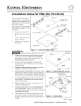
1
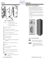
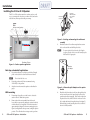
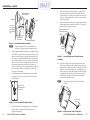
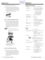
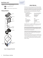
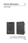
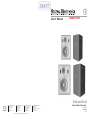
User’s Manual
DRAFT COPY
SI 26 and SI 28
www.extron.com
Extron Electronics, USA
Extron Electronics, Europe
Extron Electronics, Asia
Extron Electronics, Japan
1230 South Lewis Street
Anaheim, CA 92805
USA
714.491.1500
Fax 714.491.1517
Beeldschermweg 6C
3821 AH Amersfoort
The Netherlands
+31.33.453.4040
Fax +31.33.453.4050
135 Joo Seng Road, #04-01
PM Industrial Building
Singapore 368363
+65.6383.4400
Fax +65.6383.4664
Kyodo Building
16 Ichibancho
Chiyoda-ku, Tokyo 102-0082 Japan
+81.3.3511.7655
Fax +81.3.3511.7656
© 2006 Extron Electronics. All rights reserved.
Surface Mount Speakers
68-1164-01
Rev. Ax1
05 06
Introduction
Features
6
11
7
1
2
8
9
3
4
5
10
About the SI 26 and SI 28 Speakers
The Extron System INTEGRATOR™ SI 26 and SI 28 two-way
surface mount speakers are ideally suited for classrooms,
conference rooms, and boardrooms. With a weather resistant
construction, they are also suitable for outdoor environments.
• SI 26 features a 6.5" long-throw woofer, 1" tweeter, 150 watts
continuous program capacity, and frequency response from 70
Hz to 20 kHz.
• SI 28 features an 8" long-throw woofer, 1" tweeter, 180 watts
continuous program capacity, and frequency response from 50
Hz to 20 kHz.
Figure 1 — Speaker Features
Dimensions: SI 26: 13.0" H x 8.5" W x 6.75" D
(33.0 cm H x 21.6 cm W x 17.1 cm D)
SI 28: 16.5" H x 11.5" W x 8.6" D (41.9 cm H x 29.2 cm W x 21.9 cm D)
a
b
c
d
e
f
g
h
i
j
k
l
m
n
o
Dual tuned bass reflex ports
1" ferrofluid-cooled, aluminum dome tweeter
Front locking access (allows for speaker position adjustment)
6.5" (SI 26) or 8" (SI 28) long-throw woofer
Grill and enclosure may be painted to match environment
Weather resistant construction
Push down spring terminals
Figure 1 — Extron SI surface speakers
Wall mount assembly with unique V-Lock™ (Patent Pending)
system included
N
Back cover for use when speakers are not wall mounted
Allen hex tool
Extron logo (fits in grill to cover locking port access)
Use cable clamps to hold the cables in place for
strain relief. Trim back/insulate exposed cable
shields with heat shrink to reduce the chance of short
circuits
8 ohm nominal impedance
75 watts (SI 26) or 90 watts (SI 28) continuous pink noise
150 watts (SI 26) or 180 watts (SI 28) continuous program
Internal driver overload protection circuit
N
i
C
Extron recommends that the wiring installation is
performed by a professional audio equipment installer.
For items 12 through 15, see "Specifications", page 7 of this manual.
SI 26 and SI 28 Speakers • Features
SI 26 and SI 28 Speakers • Introduction
1
Installation
Installing the SI 26 or SI 28 Speaker
The SI 26 or SI 28 can be mounted on a surface, such as a wall
or post, or mounted in a bookcase, or under a shelf, and can be
used with any Extron product with power amps.
Rotate This
Section 90°
Fasten the
wall mount plate
to the vertical
surface.
Extron
SI 28
Surface-mount Speakers
Figure 3 — Rotating and mounting the wall mount
assembly
3.
Mark the location of the wall mount plates three center
holes on the stud line and drill the pilot holes.
N
Conference Room
Figure 2 — Surface speaker application
Alternative
pilot dimples.
Desk top or bookshelf applications
1.
For quick installation on a desk top or bookshelf, simply
place on a desk, shelf or other flat surfaces as desired.
N
Do not detach the back cover.
2.
Route the speaker wire (Extron recommends using
12-18 AWG) to the speakers.
3.
Strip the wire and connect the speakers as described on
page 6.
Wall mounting
2
For some surfaces the four alternative pilot dimples
(see figure 4) may be used to secure the assembly in place. Mark and drill as appropriate
1.
If mounting to drywall, use a stud locator to locate the
studs in the wall. Mark their position.
2.
Remove the wall mount assembly from the box and
loosen the hex cap screw (by turning it counter clockwise)
with the allen hex tool supplied. Rotate the front section
approximately 90 degrees to the rear mounting plate (see
figure 3) and tighten the hex cap screw, locking the plate in
position. This will make the next steps easier to perform.
SI 26 and SI 28 Speakers • Introduction
Figure 4 — Alternative pilot dimples on the speaker
bracket
4.
Mark the wall where the wire will pass through the plate,
and cut a small access hole large enough for the wire to
pass through without snagging. If the stud is wider than
the plates access hole, then cut the hole in the wall to the
left or right and directly alongside the stud (see figure 5).
Before cutting it, make sure the plate will cover the hole
when it is finally installed.
SI 26 and SI 28 Speakers • Installation
3
Installation, cont’d
Approximate Stud
line behind wall
Wall Stud
8.
When the assembly is securely in place, loosen the hex
cap screw (turn counter-clockwise) and rotate the front
section back into a vertical position with the hex cap screw
at the top. Using the allen hex tool, turn the hex cap screw
clockwise to tighten.
9.
Remove the cover from the back of a speaker and carefully
slide the speaker box bracket down into the V lock groove
until it locks into place (see figure 7).
Wall
Screw
Cut access
hole alongside
stud and feed
wires though
hole.
Slide the speaker onto the
wall mount assembly.
Bend wire to line
up with access
hole in plate.
Stage
Wall Mount Assembly
Figure 5 — Install wall mount assembly
N
5.
6.
Extron recommends that the wiring installation is
performed by a professional audio equipment installer.
Using compatible speaker wire (Extron recommends using
12-18 AWG), route the wire from the audio source to the SI
speaker location by the most convenient and safe route. If
the wiring is to remain hidden behind the wall, follow the
stud to where the small access hole has been cut, and feed
about two feet of wire out through the hole into the room.
If necessary, bend the wire to align with the plate (see
figure 5). Secure the wire at various places to the stud, but
allow enough freedom of movement near to the hole for
connection to the speaker
Pull sufficient wire up through the holes in the rear plate
(see figure 6) to allow ease of connection to the speaker
after installation.
Box
bracket
Figure 7 — Install speaker onto the wall mount
assembly
10. To adjust the angle of the speaker, carefully remove the
Extron logo on the front of the speaker to expose the front
locking access (see Figure 1, Item 3, for location). Insert the
allen hex tool into the locking access, and slightly loosen
the hex cap screw. Adjust the speaker to the desired angle
(see figure 8), and torque the cap screw down clockwise
until snug. The speaker will sit securely in the desired
position. Install the Extron logo.
N
The Extron logo can be fitted either horizontally or
vertically.
Pass the wires
through the plate
access hole.
Figure 6 — Pass the wire through the plate
7.
4
Place the wall mount assembly against the wall, aligning
the plate holes with those drilled, and secure with
appropriate hardware.
SI 26 and SI 28 Speakers • Installation
Turn clockwise
to tighten.
Figure 8 — Adjust speaker and lock in place
SI 26 and SI 28 Speakers • Installation
5
Specifications
Installation, cont’d
11. Repeat steps 1-10 for the second speaker.
12. When both speakers are in place, carefully pull enough
wire to reach up to the terminals at the back of the speaker
and strip the ends of the wire approximately 5/8" (15 mm),
for connection. . Twist the bared ends of each separate wire
so that they will hold firmly in the connector.
Strip approx. 15 mm (5/8”)
Twist the bared wire
Figure 9 — Strip the wire and twist the bared ends
13. Press down on the spring loaded terminals to open the
holes at the top. Observing the correct polarity, (, wire
to , terminal and . wire to . terminal) insert the
twisted wires into the relevant open holes (see figure 10)
and release the springs to secure. Push any loose wire
through the plate on the wall mount assembly and back
into the wall.
C
Do not connect the speaker terminals to one
channel in parallel (together) with those of the other
channel.
Extron
Audio/acoustic and electrical
Speaker type.................................... 2-way, indoor/outdoor surface mount
Frequency range............................. SI 26 70 Hz to 20 kHz, -10 dB, half space
SI 28 50 Hz to 20 kHz, -10 dB, half space
Power capacity............................... SI 26 150 W continuous program
75 W continuous pink noise
SI 28 180 W continuous program
90 W continuous pink noise
Nominal sensitivity........................ 90 dB SPL, 1W, 1m, half space
Nominal impedance...................... 8 ohms
Crossover frequency...................... SI 26 2.3 kHz
SI 28 2.1 kHz
Woofer.............................................. SI 26 6.5" (165 mm) polypropylene cone
SI 28 8.0" (203 mm) polypropylene cone
Tweeter............................................ 1.0" (25 mm) aluminum dome
Overload protection....................... Full range power limiter, protecting the
tweeter, woofer, and crossover
Input connector.............................. 2 pin spring terminals
General
Package............................................ 2 speakers (1 pair)
Temperature/humidity Storage: -40 to +158 °F (-40 to +70° C) / 10% to 90%,
noncondensing
Operating: +32 to +122 °F (0 to +50° C) /
10% to 90%, noncondensing
Mounting......................................... Wall mount assembly with V-lock (patent
pending)
N
INPUT
negative
wire
positive wire
Push down on the spring terminals at the
back of the speaker, and insert the wires.
Release the springs to secure.
Figure 10 — Insert wiring into the terminals
14. Turn on the audio source and any associated devices.
Follow the manufacturers instructions to adjust the source
and device settings as desired to get the optimum audio
output for your speaker application. If necessary, re-adjust
the angle of the speaker (repeat step 10) to get the best
audio area coverage.
6
SI 26 and SI 28 Speakers • Specifications
Wall mount assembly can be angled up to 20° upward, 35° downward, 30° to the left, and 30° to the right.
Enclosure type................................ Plastic, trapezoidal, with metal grille and
bass reflex ports
Enclosure outer dimensions......... SI 26: 13.0" H x 8.5" W x 6.75" D
(33.0 cm H x 21.6 cm W x 17.1 cm D)
SI 28: 16.5" H x 11.5" W x 8.6" D
(41.9 cm H x 29.2 cm W x 21.9 cm D)
Product weight............................... SI 26
11 lbs (5 kg) each
SI 28
15 lbs (6.8 kg) each
Shipping weight ............................ SI 26
30 lbs (14 kg) per pair with
mounting kit package
SI 28
40 lbs (19 kg) per pair with
mounting kit package
SI 26 and SI 28 Speakers • Specifications
7
Specifications, cont'd
Warranty.......................................... 5 years parts and labor
N
All nominal levels are at ±10%.
N
Specifications are subject to change without notice.
Packaging information
Top Foam
Allen Hex Tool
Speakers
Back Covers
Extron’s Warranty
Extron Electronics warrants this product against defects in materials and workmanship
for a period of five years from the date of purchase. In the event of malfunction during
the warranty period attributable directly to faulty workmanship and/or materials, Extron
Electronics will, at its option, repair or replace said products or components, to whatever
extent it shall deem necessary to restore said product to proper operating condition,
provided that it is returned within the warranty period, with proof of purchase and
description of malfunction to:
USA, Canada, South America,
and Central America:
Extron Electronics 1001 East Ball Road
Anaheim, CA 92805, USA
Asia:
Extron Electronics, Asia
135 Joo Seng Road, #04-01
PM Industrial Bldg.
Singapore 368363
Europe, Africa, and the Middle East:
Extron Electronics, Europe
Beeldschermweg 6C
3821 AH Amersfoort
The Netherlands
Japan:
Extron Electronics, Japan
Kyodo Building
16 Ichibancho
Chiyoda-ku, Tokyo 102-0082
Japan
This Limited Warranty does not apply if the fault has been caused by misuse, improper
handling care, electrical or mechanical abuse, abnormal operating conditions or nonExtron authorized modification to the product.
Wall Mount
Assemblies
Bottom Foam
If it has been determined that the product is defective, please call Extron and ask for an
Applications Engineer at (714) 491-1500 (USA), 31.33.453.4040 (Europe), 65.6383.4400
(Asia), or 81.3.3511.7655 (Japan) to receive an RA# (Return Authorization number). This
will begin the repair process as quickly as possible.
Units must be returned insured, with shipping charges prepaid. If not insured, you
assume the risk of loss or damage during shipment. Returned units must include the
serial number and a description of the problem, as well as the name of the person to
contact in case there are any questions.
Extron Electronics makes no further warranties either expressed or implied with respect
to the product and its quality, performance, merchantability, or fitness for any particular
use. In no event will Extron Electronics be liable for direct, indirect, or consequential
damages resulting from any defect in this product even if Extron Electronics has been
advised of such damage
Product Label
Inst
all
Par
t No.
33-
XXX
Thick Single Wall
Packing
206W
XX
X-0
X-XX Ce
X-01 iling
1
RE
Sp
eake
r
V.
Figure 9 — Packaging for SI 26 and SI 28
8
SI 26 and SI 28 Speakers • Specifications