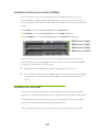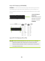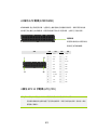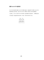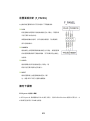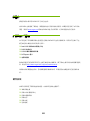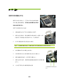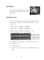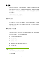
1
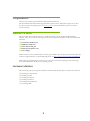
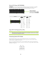
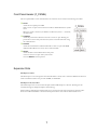
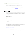
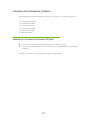
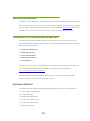
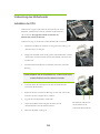
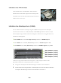
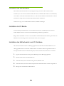
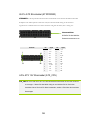
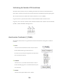
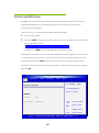
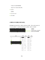
Table of Contents Congratulations! ................................................................................................2 Parts NOT in the Kit ...........................................................................................2 Hardware Installation ............................................................................................ 2 Preparing the Motherboard ................................................................................3 Installing the CPU ..........................................................................................3 Installing the CPU Fan....................................................................................3 Installing System Memory (DIMMs) ................................................................4 Installing the Motherboard .................................................................................4 Installing the I/O Shield .................................................................................4 Securing the Motherboard into a System Case .................................................5 Connecting Cables .............................................................................................5 24-pin ATX Power (ATXPOWER)................................................................ 6 4-pin ATX 12V Power (ATX_CPU) .................................................................... 6 Connecting Serial ATA Cables .........................................................................6 Front Panel Header (F_PANEL) .......................................................................7 Expansion Slots .............................................................................................7 PCI Express x1 Slots ........................................................................................ 7 PCI Express x16/x8/x1 Slots ............................................................................ 7 Enter BIOS Setup ..............................................................................................8 Installing Drivers and Software ............................................................................. 9 Windows XP/Vista/7 Driver Installation ...............................................................9 1 Congratulations! Thank you for purchasing this EVGA P55 Chipset based motherboard. This motherboard from EVGA offers high performance, quality features and superior support. If you have any questions about this product please visit www.evga.com to read the EVGA FAQ, visit our forums or contact us directly. Parts NOT in the Kit This kit contains all the hardware necessary to install and connect your new EVGA P55 Motherboard. However, it does not contain the following items that must be purchased separately to make the motherboard functional. Intel Socket 1156 Processor DDR3 System Memory Socket 1156 Cooling fan PCI Express Graphics Card Power Supply EVGA assumes you have purchased all the necessary parts needed to allow for proper system functionality. For a full list of supported CPU’s on this motherboard, please visit http://www.evga.com/support/motherboard/. When replacing a motherboard in a system case, you will need to reinstall an operating system even though the current hard disk may already have an operating system Hardware Installation This section will guide you through the installation of the motherboard. The topics covered in this section are: Preparing the motherboard Installing the CPU Installing the CPU fan Installing the memory Installing the motherboard Connecting cables 2 Preparing the Motherboard Installing the CPU Be very careful when handling the CPU. Hold the processor only by the edges and do not touch the contacts on the motherboard or CPU. Any physical damage to the motherbard pins will void the warranty. Use the following procedure to install the CPU onto the motherboard: 1. Unhook the socket lever by pushing down and away from the socket. 2. Pull the socket lever back and the load plate will automatically lift. There is a protective socket cover within the CPU socket to protect the socket when there is no CPU installed. 3. Remove the protective socket cover from the CPU Socket in a straight up motion. Note: You must save the protective cover so that whenever you remove the CPU the pins will not be protected. 4. Align the notches in the processor with the notches on the socket. 5. Lower the processor straight down into the socket without tilting or sliding it into the socket 6. Lower the load plate so it is resting on the CPU. 7. Pull back the socket lever again to ensure the load plate tip engages under the shoulder screw cap. 8. Carefully close and latch the lever. Align notches with notches on the CPU Installing the CPU Fan There are many different fan types that can be used with this motherboard. Follow the instruction that came with you fan assembly. Be sure that the fan orientation is correct for your chassis type and your fan assembly. 3 Installing System Memory (DIMMs) Your new motherboard has four 240-pin slots for DDR3 memory. These slots support 512 MB, 1GB, 2GB, and 4GB DDR3 technologies. There must be at least one memory bank populated to ensure normal operation. Use the following the recommendations for installing memory. One DIMM: If using 1 DIMM (Single Channel), install into: DIMM slot 1. Two DIMMs: If using 2 DIMMs (Dual Channel), install into: DIMM slots 1 and 3. Four DIMMS: If using 4 DIMMs (Dual Channel), install into: DIMM slots 2, 1, 4, and 3. DIMM Slot 2 (XMM2) DIMM Slot 1 (XMM1) DIMM Slot 4 (XMM4) DIMM Slot 3 (XMM3) Use the following procedure to install memory DIMMs. Note that there is only one gap near the center of the DIMM slot. This slot matches the slot on the memory DIMM to ensure the component is installed properly. 1. Unlock a DIMM slot by pressing the module clips outward. 2. Align the memory module to the DIMM slot, and insert the module vertically into the DIMM slot. The plastic clips at both sides of the DIMM slot automatically lock the DIMM into the connector. Installing the Motherboard The sequence of installing the motherboard into a system case depends on the chassis you are using and if you are replacing an existing motherboard or working with an empty system case. Determine if it would be easier to make all the connections prior to this step or to secure the motherboard and then make all the connections. It is normally easier to secure the motherboard first. Use the following procedure to install the I/O shield and secure the motherboard into the chassis. Installing the I/O Shield The motherboard kit comes with an I/O shield that is used to block radio frequency transmissions, protects internal components from dust and foreign objects, and promotes correct airflow within the chassis. Before installing the motherboard, install the I/O shield from the inside of the chassis. Press the I/O shield into place and make sure it fits securely. 4 Securing the Motherboard into a System Case Most system cases have a base with mounting studs or spacers to allow the motherboard to be secured to the chassis and help to prevent short circuits. If there are studs that do not align with a mounting hole on the motherboard, it is recommended that you remove that stud to prevent the possibility of a short circuit. 1. Carefully place the motherboard onto the stand offs located inside the chassis. 2. Align the mounting holes with the stand offs. 3. Align the connectors to the I/O shield. 4. Ensure that the fan assembly is aligned with the chassis vents according to the fan assembly instruction. 5. Secure the motherboard with screws. Connecting Cables This section takes you through all the necessary connections on the motherboard. This will include: Power Connections 24-pin ATX power (ATXPOWER) 4-pin ATX 12V power (ATX_CPU) Internal Headers Front panel Serial ATA II Expansion slots 5 24-pin ATX Power (ATXPOWER) ATXPOWER is the main power supply connector located along the edge of the board next to the DIMM slots. Make sure that the power supply cable and pins are properly aligned with the connector on the motherboard. Firmly plug the power supply cable into the connector and make sure it is secure. Power Connector Plug power cable from system power supply to ATXPOWER Connector 1 13 Pin 12 24 Signal Pin Signal 1 +3.3V 13 +3.3V 2 +3.3V 14 -12V 3 GND 15 GND 4 +5V 16 PS_ON 5 GND 17 GND 6 +5V 18 GND 7 GND 19 GND 8 PWROK 20 RSVD 9 +5V_AUX 21 +5V 10 +12V 22 +5V 11 +12V 23 +5V 12 +3.3V 24 GND 4-pin ATX 12V Power (ATX_CPU) ATX_CPU the 4-pin or 8-pin ATX 12V power connection, is used to provide power to the CPU. Align the pins to the connector and press firmly until seated. If using an 8-pin connector, 4 of the pins will overhang the connector. Connecting Serial ATA Cables The Serial ATA II connector is used to connect the Serial ATA II device to the motherboard. These connectors support the thin Serial ATA II cables for primary storage devices. The current Serial ATA II interface allows up to 300MB/s data transfer rate. There are six (5) internal serial ATA connectors on this motherboard. These connections are designed to be angled to not interfere with any expansions cards. These connection points support RAID 0, RAID 1, RAID5 and RAID 10 configurations. 6 Front Panel Header (F_PANEL) The front panel header on this motherboard is one connector used to connect the following four cables. PLED Attach the front panel power LED cable to these two pins of the connector. The Power LED indicates the system’s status. When the system is turned on, the LED is on. When the system is turned off, the LED is off. PWRBTN Attach the power button cable from the case to these two pins. Pressing the power button on the front panel turns the system on and off rather than using the onboard button. HDLED Attach the hard disk drive indicator LED cable to these two pins. The HDD indicator LED indicates the activity status of the hard disks. RESET Attach the Reset switch cable from the front panel of the case to these two pins. The system restarts when the RESET switch is pressed. Expansion Slots PCI Express x1 Slots The PCI Express x1 slot is designed to accommodate PCIe x1 cards, such as an EVGA Killer Xeno Network Card or Sound Card. The x1 slot provides 250 MB/sec bandwidth. PCI Express x16/x8/x1 Slots These PCI Express slots are reserved for Graphic Cards and PCI Express x1 devices. The design of this motherboard supports multiple Graphic Card technology. When installing a PCI Express Graphic Card, be sure the retention clip snaps and locks the card into place. Secure the card’s metal bracket to the chassis back panel with the screw used to hold the blank cover. 7 Enter BIOS Setup The BIOS is the communication bridge between hardware and software. Correctly setting the BIOS parameters is critical to maintain optimal system performance and stability. Use the following procedure to verify/change BIOS settings. 1. Power on the computer. 2. Press the Del key when the following message briefly displays at the bottom of the screen during the Power On Self Test (POST). Press F9 to Load Defaults, DEL to enter Setup. Pressing Del takes you to the AMI BIOS CMOS Setup Utility. The main menu allows you to select from the list of setup functions and two exit choices. Use the + and keys to scroll through the options or press Enter to display the associated submenu. Use the arrow keys to position the selector in the option you choose. To go back to the previous menu, press Esc. BIOS SETUP UTILITY Main Advanced Power Security Boot Exit Use [ENTER], [TAB] System Overview Or [SHITF-TAB] to Select a field. AMIBIOS Version : 0307 Use [+] or [-] to Build Date : 10/20/09 Select Screen Configure system Time. System Memory Size : 4096MB Select Item +- Change Field Tab Select Field v02.67 (C)Copyright 1985-2009, American Megatrends, Inc. System Time [10:19:32] System Date [Mon 10/26/2009] 8 F1 General Help F10 Save and Exit ESC Exit Installing Drivers and Software The CD that has been shipped with the EVGA P55 Motherboard contains the following software and drivers: Chipset Drivers Audio drivers LAN Drivers RAID Drivers Adobe Acrobat Reader User’s Manual Windows XP/Vista/7 Driver Installation 1. Insert the Intel P55 installation CD for the motherboard included in the kit. 2. The CD will autorun, install the drivers and utilities listed on the install screen. If the CD does not run, go to My Computer and click on the CD to open. 9 もくじ ようこそ! ........................................................................................................ 11 同梱されない付属品 ......................................................................................... 11 ハードウェアを取り付ける ................................................................................ 12 始める前に ...................................................................................................... 12 CPU を取り付ける .......................................................................................... 12 CPU ファンを取り付ける .................................................................................. 13 システムメモリ(DIMMs)を取り付ける ................................................................ 13 マザーボードを取り付ける .................................................................................. 14 I/O シールドを取り付ける ............................................................................... 15 マザーボードをケースへ固定する .................................................................... 15 配線ケーブル .................................................................................................. 15 24-ピン ATX 電源 (ATXPOWER)………………………………………………….16 4-ピン ATX 12V 電源 (ATX_CPU) ……………………….………………………16 シリアル ATA ケーブルの接続 ........................................................................ 17 拡張スロット PCI Express x1 スロット ............................................................... 18 PCI Express x16/x8/x1 スロット….………………………………………………...18 BIOS のセットアップ .......................................................................................... 19 ドライバとソフトウェアのインストール ......................................................................... 20 Windows XP/Vista/7 ドライバのインストール......................................................... 20 10 ようこそ! EVGA P55 チップセット搭載マザーボードをお買い上げいただきありがとうございます。 このマザーボードは EVGA から高性能、高品質の機能、および優れたサポートを提供するマザーボー ドです。 この製品に関する質問がありましたら、www.evga.com にアクセスして、EVGA FAQ を読むか、 フォーラムを訪問するか、または直接連絡してください。 同梱されない付属品 このバッケージには EVGA P55 マザーボードに取り付け、または接続するのに必要なハードウェアが付 いています。ところが 、以下の商品はマザーボードを機能的にする必要項目ですが、同梱されませんの で、別途にご購入ください。 Intel プロセッサ 1156 ソケット DDR3 システム メモリ Socket 1156 ソケット冷却ファン PCI Express グラフィックカード 電源ユニット EVGA は、お客様が適切なシステムの機能性のため、必要な付属品を購入したと仮定しますので、本マ ザーボードでは CPU をサポートするものに関するは、下記へご訪問ください。 http://www.evga.com/support/motherboard/. ケースにマザーボードを取り替えるとき、今のハードディスクにはオペレーティングシステムが既にあるか もしれませんが、オペレーティングシステムを再インストールする必要があります。 11 ハードウェアを取り付ける この章では、マザーボードの設置手順についてご案内します。また、それに関連する項目、以下 の通りです: マザーボードを取り付ける CPU を取り付ける CPU ファンを取り付ける メモリを取り付ける マザーボードを取り付ける 配線ケーブル 始める前に CPU を取り付ける CPU の取り扱いにはよくご注意ください。必ずプロセッサのエッジ 部分を持ち、、マザーボードや CPU の接点には触れないでくだ さい。マザーボードピンへのいかなる物理的なダメージにより、保 証が無効となります。以下の手順で、CPU をマザーボードに取り 付けます: 1. ソケットレバーを押し下げ、ソケットから離すようにして、レバーを外に 動かします。 2. ソケットレバーを開くと、ロードプレートは自動的に上がます。 CPU ソケットにあるソケットカバーは CPU をまた、取り付けないとき、ソ ケットの損傷を防ぐことができます。 12 3. CPU ソケットからソケットカバーを垂直の方向に取り出します。 注意: ピンの損傷を防ぐため、CPU を取り外したときに、保護カバーは必ず収納しなければなりま りません。 4. ソケットの突出をプロセッサの切り欠きに合わせます。 5. プロセッサを傾けたり滑らせたりせずに、ソケットにまっすぐ下ろします。 6. ロードプレートを押し下げて閉じ、CPU の上に置きます。 7. ロードプレートの先端はスクリューキャップの上にあるのを確保するた め、もう一度ソケットレバーを引き返します。 ソケットの突出をプ 8. 慎重に閉じて、レバーをロックします。 ロセッサの切り欠き に合わせます。 e CPU CPU ファンを取り付ける このマザーボードはさまざまなファンに対応します。以下の手順で、 ファンの取り付けをご案内します。 システムメモリ(DIMMs)を取り付ける お使いのマザーボードには DDR3 メモリ用の 240-ピンスロットが四本あります。これらのスロットには 512 MB、1GB、2GB、および 4GB の DDR3 技術をサポートします。正常な動作を確認するため、少なくとも 1 つのメモリスロットを装着する必要があります。メモリの取り付けについては、次のような組み合わせ方法 をお勧めします。 One DIMM: 1 DIMM (シングル チャンネル) を使用する場合, DIMM スロット 1 に取り付けます. 13 Two DIMMs: 2 DIMMs (デュアルチャンネル) を使用する場合, DIMM スロット 1 と 3 に取り付けます. Four DIMMS: 4 DIMMs (デュアルチャンネル) を使用する場合, DIMM スロット 2, 1, 4, と 3 に取り付 けます. DIMM スロット 2 (XMM2) DIMM スロット 1 (XMM1) DIMM スロット 4 (XMM4) DIMM スロット 3 (XMM3) メモリ DIMMsの取り付けについては、以下の手順をご参照くだい。DIMM スロットの中央付 近に 1 つだけのギャップがあることにご注意ください 。コンポーネントを正常に取り付けるために、 このスロットは、メモリ DIMM 上のギャップに必ず合わせます。モジュールクリップの外部を押し、 DIMM スロットのロックを解除します。 1. モジュールクリップの外部を押し、DIMM スロットのロックを解除します。 2. メモリモジュールを DIMM スロットに合わせ、モジュールを DIMM スロットに垂直方向に挿入します。 DIMM スロットの両側にあるプラスチック製のクリップが自動的にコネクタに、DIMM をロックします。 マザーボードを取り付ける マザーボードをシステムケースに取り付ける手順については、お使いのシャーシ、または既存のマザーボー ドを交換したり、空のシステムケースを使用したりすることによって決まります。 このステージに先だって、最初に各種コネクタを接続してから、マザーボードを固定するか、またはマザー ボードを固定してから、各種コネクタを接続するか、どれが簡単か選んでください。 以下の手順に従い、I/O シールドを取り付け、またマザーボードをシャーシに固定します。 14 I/O シールドを取り付ける マザーボードには、無線周波数の送波を防ぐために使用されたり、ほこりや異物の侵入から内部のコン ポーネントを保護したり、シャーシ内の空気の流れを助けたりする I/O シールドが付いています。 マザーボードを取り付ける前に、先にシャーシの内側に I/O シールドを取り付けます。I / O シールドを 押して、しっかりと正しい位置に収まるように、ご確認ください。 マザーボードをケースへ固定する ほとんどのケースには、マザーボードをシャーシに固定し、また短絡を防ぐために、取り付け用ネジと、ス ペーサーが付いています。 ネジはマザーボード上のネジ穴に合わせない場合、短絡の可能性を防ぐため、スペーサーを取り外す のをお勧めします。 1. 2. 慎重に、マザーボードをシャーシ内のマザーボードマウンタの上に置きます。 3. I / O シールドに、コネクタを合わせます。 4. アセンブリに関する指示により、ファンはシャーシ通気孔に合わせていることを確認します。 5. ネジでマザーボードを固定します。 マザーボードマウンタにネジ穴を合わせます。 配線ケーブル この章では、マザーボード上のすべての必要な接続をご案内します。次のようなものが含まれています: 電源コネクタ 24-ピン ATX 電源 (ATXPOWER) 4-ピン ATX 12V 電源 (ATX_CPU) 内部ヘッダー フロントパネル シリアル ATA II 拡張スロット 15 24-ピン ATX 電源 (ATXPOWER) ATXPOWER は DIMM スロットの隣に、ボードの縁のに沿って置かれる主電源用のコネクタです。電源 供給ケーブルとピンは適切にマザーボード上のコネクタに合わせて付けられていることを確認します。電 源供給ケーブルをコネクタにしっかりと埋め込み、それは安全であることを確認してください。 電源コネクタ 電源ユニットから電源ケーブ ルを ATXPOWER に差し込み ます。 コネクタ 1 ピン 12 13 24 信号 ピン 信号 1 +3.3V 13 +3.3V 2 +3.3V 14 -12V 3 GND 15 GND 4 +5V 16 PS_ON 5 GND 17 GND 6 +5V 18 GND 7 GND 19 GND 8 PWROK 20 RSVD 9 +5V_AUX 21 +5V 10 +12V 22 +5V 11 +12V 23 +5V 12 +3.3V 24 GND 4-ピン ATX 12V 電源 (ATX_CPU) ATX_CPU 4 ピンまたは 8 ビン ATX 12V 電源コネクタは、CPU に電力を提供するために使用されます。 固定されるまでコネクタにピンを合わせて、しっかり押します。8 ピンのコネクタの場合は、4 本のピ ンがネクタに張り出します。 16 シリアル ATA ケーブルの接続 シリアル ATA II コネクタは、マザーボードにシリアル ATA II デバイスを接続するために使用されます。 これらのコネクタは、主要なストーレジデバイス用の薄型シリアル ATA II ケーブルをサポートします。現 在のシリアル ATA II インターフェイスは最大 300MB/sの転送速度が可能です。 このマザーボードに内部シリアル ATA コネクタが 6(5)つあります。これらのコネクタはすべての拡張カ ードと干渉しないようにアングルに設計されます。 フロントパネルヘッダー (F_PANEL) このマザーボード上のフロントパネルヘッダーは、次の 4 本のケーブルを接続するために使用されるコ ネクタです。 PLED フロントパネルの電源 LED ケーブルを 2 つのコネクタピンに取り 付けます。電源 LED は、システムのステータスを示します。 システムがオンになると、LED が点灯します。 システムがオフになると、LED が消灯します。 PWRBTN 電源ボタンのケーブルをこの 2 つのピンに取り付けます。また、フロントパ ネルの電源ボタンを押し、システムをオフ/オフにするより、むしろオンボー ドのボタンを使用するほうがいいです。 HDLED HDD インジケータの LED ケーブルをこの 2 本のピンに取り付けます。 HDD インジケータの LED はハードディスクの活動状態を示します。 17 RESET ケースのフロントパネルから Reset スイッチケーブルをこの 2 本のピンに取り付けます。 RESET スイッチを押すと、システムが再起動します。 拡張スロット PCI Express x1 スロット PCI Express x1 スロットは EVGA Killer Xeno のネットワーク用カードやサウンドカードなどの PCIe x1 カ ードに対応するように設計されます。この x1 スロットは 250 MB /秒の帯域幅をサポートします。 PCI Express x16/x8/x1 スロット これらの PCI Express スロットはグラフィックカードと PCI Express x1 装置のために留保されます。本マザ ーボードの設計は、複数のグラフィックカード技術をサポートします。 PCI Express グラフィックカードを取り付けるときは、必ずクリップスナップがカードを所定の場所にロック するのを確認します。 空白カバーを固定するため,カードの金属製のブラケットをネジで、シャーシ背面パネルには固定します。 18 BIOS のセットアップ BIOS はハードウェアとソフトウェアとの間に通信するブリッジです。BIOS パラメータの正確 な設定によって、重要なシステムのパフォーマンスと安定性を維持できます。 以下の手順で BIOS 設定を確認/変更します。 1. コンピュータの電源をオンにします。 2. 自己診断テスト(POST)チェック中に、次のメッセージが画面の最下段に簡潔に表示されるとき、 Del キーを押します。 Press F9 to Load Defaults, DEL to enter Setup. Del を押すと、AMI の BIOS CMOS セットアップ画面に入ります。 メインメニューでは、機能設定と二つの EXIT 項目を選択できます。+と-キーを使用して、オプションをス クロールし、或いは Enter を押して、サブメニューを表示させます。矢印キーを使用して、選んだオプ ションにセレクターを移動します。また、Esc を押すと、前のメニューに戻ります。 BIOS SETUP UTILITY Main Main Advanced Power Security Boot Exit Use [ENTER], [TAB] System Overview Or [SHITF-TAB] to Select a field. AMIBIOS Version : 0307 Use [+] or [-] to Build Date : 10/20/09 Select Screen Configure system Time. System Memory Size : 4096MB Select Item +- Change Field Tab Select Field v02.67 (C)Copyright 1985-2009, American Megatrends, Inc. System Time [10:19:32] System Date [Mon 10/26/2009] 19 F1 General Help F10 Save and Exit ESC Exit ドライバとソフトウェアのインストール EVGA P55 マザーボードと同梱される CD には、次のソフトウェアとドライバが付いています: チップセットドライバ オーディオ ドライバ LAN ドライバ RAID ドライバ Adobe Acrobat Reader プログラム ユーザー マニュアル Windows XP/Vista/7 ドライバのインストール 1. 同梱にはマザーボード用 Intel P55 のインストール CD を差し込みます。 2. この CD は自動実行し、画面に記載されるドライバとユーティリティをインストールします。 この CD は自動実行しない場合は、[マイコンピュータ]を開き、CD をクリックします。 20 Tabla de Contenidos ¡Felicidades! ........................................................................................................... 22 Partes no incluidas en Juego ................................................................................. 22 Instalación de Hardware .............................................................................................22 Preparación de Placa base ................................................................................... 23 Instalación del ventilador de CPU ..................................................................... 23 Instalación de Memoria de sistema (DIMMs) ..................................................... 24 Instalación de Placa base ...................................................................................... 24 Instalación de Capa protectora de I/O ............................................................... 25 Asegurar Placa base en Caja de Sistema ......................................................... 25 Conexión de Cables ............................................................................................... 25 24-pin ATX Potencia (ATXPOWER) ............................................................... 26 4-pin ATX 12V Potencia (ATX_CPU) .............................................................. 26 Conexión de Cables Seriales ATA ..................................................................... 27 Cabecera de Panel Frontal (F_PANEL) ............................................................. 28 Ranuras de Expansión ....................................................................................... 29 PCI Express x1 Ranura ................................................................................... 29 PCI Express x16/x8/x1 Ranuras ..................................................................... 29 Entrar en Configuración de BIOS .......................................................................... 30 Instalación de Controladores y Software ....................................................................31 Instalación de Controladores de Windows XP/Vista/7............................................ 31 21 ¡Felicidades! Gracias por comprar este Chipset EVGA P55 basadO EN placa base. La placa base de EVGA se ofrece un alto rendimiento, características de calidad y apoyo superior. Si usted tiene alguna pregunta sobre este producto, por favor visite www.evga.com para leer FAQ de EVGA, visite nuestros foros o entre en contacto con nosotros directamente. Partes no incluidas en Juego Este producto se contiene todos los hardwares necesarios para instalar y conectar su nueva Placa base EVGA P55. Sin embargo, no se contiene los itemes siguientes que deben comprarse separadamente para hacer la placa base funcional. Intel Socket 1156 Procesador Memoria de Sistema DDR3 Ventilador Frío de Zócalo 1156 Tarjeta Gráfica de PCI Express Fuente de Alimentación EVGA se le supone comprar todas las piezas necesarias para hacer la funcionalidad correcta del sistema. Para obtener una lista completa de CPU soportado en esta placa base, por favor visite http://www.evga.com/support/motherboard/. Al reemplazar una placa base en una caja del sistema, tendrá que volver a instalar un sistema operativo a pesar de que el disco duro actual ha tenido un sistema operativo Instalación de Hardware Esta sección le guiará la instalación de la placa base. Los temas son incluidos en esta sección como los siguientes: Preparación de placa base Instalación de CPU Instalación del ventilador de CPU Instalación de memoria Instalación de placa base Conexión de cables 22 Preparación de Placa base Instalación de CPU Tenga mucho cuidado al tomar CPU. Tome el procesador sólo por los bordes y no toque la placa base o CPU. Cualquier daño físico a los pines de la placa base se anulará la garantía. Utilice el procedimiento siguiente para instalar CPU en la placa base: 1. Desenganche la palanca del zócalo por presionando hacia abajo y lejos del zócalo. 2. Tire de la palanca del zócalo y la placa de carga se va a elevar automáticamente. Hay una cubierta protectora del zócalo dentro del zócalo de CPU para protegerlo cuando no hay CPU instalado. 3. Quite la cubierta protectora del zócalo de CPU del Zócalo de CPU en un movimiento hacia arriba. Nota: Usted debe conservar la cubierta protectora para que no serán protegidos los pines al quitar CPU. 4. Alinee las muescas en el procesador con las muescas en el zócalo. 5. Baje el procesador directamente hacia bajo en el zócalo sin inclinar o deslizar en el zócalo. 6. Baje la placa de carga por lo que se queda en CPU. 7. Tire la palanca del zócalo de nuevo para asegurar de que la punta de la placa de carga se quede debajo de la tapa de tornillo de hombro. 8. Cierre y trabe la palanca cuidadosamente. Alinee las muescas en el Instalación del ventilador de CPU Hay muchos diferentes tipos de ventiladores que pueden utilizarse en esta placa base. Por favor siga las instrucciones que venían con el conjunto de su ventilador. Asegúrese de que la orientación del ventilador es correcta para su tipo de chasis y el conjunto del ventilador. 23 procesador con las muescas en el zócalo. Instalación de Memoria de sistema (DIMMs) Su nueva placa base hay cuatro ranuras de 240-pin para la memoria DDR3. Estas ranuras se apoya las tecnologías DDR3 de 512 MB, 1GB, 2GB y 4GB. Debe contar se con un banco último de memoria por lo menos para garantizar el funcionamiento normal. Utilice las recomendaciones siguientes para la instalación de memoria. Un DIMM: Se utiliza 1 DIMM (Ú nico Canal), instale a: DIMM ranura 1. Dos DIMMs: Se utiliza 2 DIMMs (Dual Canal), instale a: DIMM ranuras 1 y 3. Cuatro DIMMS: Se utiliza 4 DIMMs (Dual Canal), instale a: DIMM ranuras 2, 1, 4, y 3. DIMM Ranura 2 (XMM2) DIMM Ranura 1 (XMM1) DIMM Ranura 4 (XMM4) DIMM Ranura 3 (XMM3) Utilice el procedimiento siguiente para instalar la memoria DIMMs. Tenga en cuenta que sólo hay una abertura cerca del centro de la ranura DIMM. Esta ranura se coincida con la ranura en la memoria DIMM para garantizar la instalación del componente correcta. 1. Desbloquée una ranura DIMM por presionando los clips del módulo hacia el exterior. 2. Alinee el módulo de memoria a la ranura DIMM e inserte el módulo verticalmente en la ranura DIMM. Los clips plásticos en los ambos lados de la ranura DIMM van a bloquearse automáticamente en el conector. Instalación de Placa base La secuencia de la instalación de la placa base en una caja del sistema se depende del chasis que usted esté utilizando y si va a reemplazar una placa base existente o trabajar con una caja de sistema vacía. Determina si sería más fácil hacer todas las conexiones antes de este paso o fijar la placa base y entonces hace todas las conexiones. Es más fácil normalmente de fijar la placa base primeramente. Utilice el procedimiento siguiente para instalar la capa protectora de I/O y fije la placa base en el chasis. 24 Instalación de Capa protectora de I/O La placa base se viene con una capa protectora de I/Oque es utilizada para bloquear las transmisiones de radiofrecuencia, y proteger los componentes internos del polvo y los objetos extraños, y garantizar el flujo del aire correcto dentro del chasis. Antes de instalar la placa base, instale la capa protectora de I/O de la parte interior del chasis. Presione la capa protectora de I/O en su lugar y asegúrese de que esté instalada seguramente. Asegurar Placa base en Caja de Sistema La mayoría de las cajas del sistema se cuenta con una base con los pernos del montaje o los separadores para permitir que la placa base pueda fijar bien en el chasis y lo que se ayuda a evitar los cortocircuitos. Si los pernos no se alinean con el agujero del montaje en la placa base, es recomendable que quite el perno para evitar la posibilidad de un cortocircuito. 1. Coloque la placa base encima del soporte situado dentro del chasis cuidadosamente. 2. Alinee los agujeros del montaje con los soportes. 3. Alinee los conectores en la capa protectora de I/O. 4. Asegúrese de que el conjunto del ventilador se alinee con las respiraderos del chasis de acuerdo a las instrucciones del conjunto del ventilador. 5. Fije la placa base con los tornillos. Conexión de Cables Esta sección le guiará todas las conexiones necesarias en la placa base. Se incluirá: Conexiones de Alimentación 24-pin ATX potencia (ATXPOWER) 4-pin ATX 12V potencia (ATX_CPU) Encabezadoras Interiores Panel Frontal Serial ATA II Ranuras de Expansión 25 24-pin ATX Potencia (ATXPOWER) ATXPOWER es el conector de la fuente de alimentación principal situado al borde de la placa cerca de las ranuras DIMM. Asegúrese de que el cable de la fuente de alimentación y los pines están alineados con el conector de la placa base correctamente. Conecte el cable de la fuente de alimentación al conector y asegúrese de fijar bien. Conector de fuente de alimentació n Enchufe el cable de fuente de alimentación de la fuente de alimentación del sistema a ATXPOWER Conector 1 13 Pin 12 24 Señ al Pin Señ al 1 +3.3V 13 +3.3V 2 +3.3V 14 -12V 3 GND 15 GND 4 +5V 16 PS_ON 5 GND 17 GND 6 +5V 18 GND 7 GND 19 GND 8 PWROK 20 RSVD 9 +5V_AUX 21 +5V 10 +12V 22 +5V 11 +12V 23 +5V 12 +3.3V 24 GND 4-pin ATX 12V Potencia (ATX_CPU) ATX_CPU la conexión de fuente de alimentación de 4-pin o 8-pin ATX 12V, se utiliza para proporcionar la potencia a CPU. Alinee los pins en el conector y los presione fuertemente hasta que instale bien. Si utiliza un conector de 8-pin, 4 de los pines se van a colgar el conector encima. 26 Conexión de Cables Seriales ATA El conector Serial ATA II se utiliza para conectar el dispositivo Serial ATA II a la placa base. Estos conectores se apoyan los cables finos de Serial ATA II para los dispositivos del almacenamiento primario. La actual interfaz Serial ATA II se permite hasta la velocidad de transferencia de datos de 300MB/s. Hay seis (5) conectores internos Serial ATA en esta placa base. Estas conexiones se diseñan para ser un ángulo para no interferir con cualquier tarjeta de expansión. Estos puntos de conexión se apoyan las configuraciones RAID 0, RAID 1, RAID 5 y RAID 10. 27 Cabecera de Panel Frontal (F_PANEL) La cabecera del panel frontal en esta placa base es un conector utilizado para conectar los cuatro cables siguientes. PLED Conecte el cable de LED de la fuente de alimentación del panel frontal a estos dos pines del conector. El LED de fuente de alimentación se indica el estado del sistema. Cuando el sistema está encendido, el LED se brilla. Cuando el sistema está apagado, el LED no se brilla. PWRBTN Conecte el cable del botón de fuente de alimentación de la caja a estos dos pines. Al presionar el botón de fuente de alimentación en el panel frontal se activa o se desactiva el sistema y en lugar de utilizar el botón al bordo. HDLED Conecte el cable de LED del indicador del controlador del disco duro a estos dos pines. El LED del indicador HDD se indica el estado de la actividad de los discos duros. RESET Conecte el cable del interruptor reinicial del panel frontal de la caja a estos dos pines. El sistema se reiniciará cuando se presiona el interruptor RESET. 28 Ranuras de Expansión PCI Express x1 Ranura PCI Express x1 ranura se diseña para acomodar las tarjetas PCIe x1, tales como una Tarjeta de Red EVGA Killer Xeno o Tarjeta de Sonido. La x1 ranura se proporciona un ancho de banda de 250 MB/seg. PCI Express x16/x8/x1 Ranuras Estas ranuras PCI Express se reservan por Tarjetas Gráficas y los dispositivos PCI Express x1. El diseño de esta placa base se apoya la tecnología de Tarjetas Gráficas múltiples. Al instalar una Tarjeta Gráfica PCI Express, asegúrese de que el clip de retención se cierre y se bloquée la tarjeta en su lugar. Fije el soporte de metal de la tarjeta al panel posterior del chasis con el tornillo para sujetar la cubierta del espacio vacío. 29 Entrar en Configuración de BIOS El BIOS es el puente de comunicación entre el hardware y el software. La configuración correcta de los parámetros del BIOS es importante para mantener el rendimiento y la estabilidad óptimo del sistema. Utilice el procedimiento siguiente para comprobar/cambiar las configuraciones de BIOS. 1. Encienda el ordenador. 2. Presione la tecla Del cuando el mensaje siguiente se demuestra brevemente en la parte inferior de la pantalla durante la Prueba de Encendido Por SíMismo (POST). Press F9 to Load Defaults, DEL to enter Setup. Presionando Del para la utilidad de Configuración de AMI BIOS CMOS. El menú principal le permite a seleccionar en la lista de las funciones de configuración y dos opciones de salida. Utilice las teclas + y - para desplazarse en las opciones o presione Enter para demostrar el submenú asociado. Utilice las teclas de flecha para localizar el selector en la opción que usted ha selecionado. Y vuelva al menú anterior, presione ESC. BIOS SETUP UTILITY Main Main Advanced Power Security Boot Exit Use [ENTER], [TAB] System Overview Or [SHITF-TAB] to Select a field. AMIBIOS Version : 0307 Use [+] or [-] to Build Date : 10/20/09 Select Screen Configure system Time. System Memory Size : 4096MB Select Item +- Change Field Tab Select Field v02.67 (C)Copyright 1985-2009, American Megatrends, Inc. System Time [10:19:32] System Date [Mon 10/26/2009] 30 F1 General Help F10 Save and Exit ESC Exit Instalación de Controladores y Software El CD integrado por la placa base EVGA P55 se cuenta con el software y los controladores siguientes: Controladores de Chipset Controladores de Audio Controladores de LAN Controladores de RAID Adobe Acrobat Reader Manual del Usuario Instalación de Controladores de Windows XP/Vista/7 1. 2. Inserte el CD de instalación de Intel P55 para la placa base incluido en el juego. El CD se ejecuta automáticamente, instale los controladores y las utilidades listados en la pantalla de instalación. Si el CD no se funciona, va a Mi Computadora y haga clic en CD para abrirlo. 31 Inhaltsverzeichnis Herzlichen Glückwunsch! ....................................................................................... 33 Teile die NICHT im Lieferumfang enthalten sind ................................................... 33 Hardware Installation ..................................................................................................33 Vorbereitung des Motherboards ............................................................................ 34 Installation der CPU ........................................................................................... 34 Installation des CPU Kühlers ............................................................................. 35 Installation des Arbeitsspeichers (DIMMs) ......................................................... 35 Installation des Motherboards ................................................................................ 36 Installation der I/O Blende .................................................................................. 36 Installation des Motherboards in ein PC-Gehäuse ............................................ 36 Verbindung der Kabel ............................................................................................ 37 24-Pin ATX Stromkabel (ATXPOWER)........................................................... 38 4-Pin ATX 12V Stromkabel (ATX_CPU) ......................................................... 38 Verbindung der Seriellen ATA Anschlüsse ........................................................ 39 Anschluss der Frontleiste (F_PANEL) ............................................................... 39 Weitere Steckplätze ........................................................................................... 40 PCI Express x1 Steckplätze ............................................................................ 40 PCI Express x16/x8/x1 Steckplätze ................................................................ 40 Aufrufen des BIOS Setup ....................................................................................... 41 Installation von Treibern und Software .......................................................................42 Windows XP/Vista/7 Treiber Installation ................................................................ 42 32 Herzlichen Glückwunsch! Vielen Dank, dass Sie sich für dieses auf dem EVGA P55 Chipset basierende Motherboard entschieden haben. Dieses Motherboard von EVGA bietet High-Performance, qualitätvolle Ausstattung und überlegenen Support. Sollten sie Fragen zu diesem Produkt haben so besuchen sie bitte die Webseite www.evga.com und werfen Sie einen Blick in das EVGA FAQ, besuchen Sie das Forum oder treten Sie direkt mit uns in Kontakt. Teile die NICHT im Lieferumfang enthalten sind Im Lieferumfang enthalten sind alle Bestandteile, die für den Anschluss und die Installation Ihres neuen EVGA P55 Motherboards benötigt werden. Allerdings sind folgende Bestandteile nicht enthalten und müssen daher separat erworben werden. Intel Socket 1156 Prozessor DDR3 Arbeitspeicher Socket 1156 CPU Lüfter PCI Express Grafikkarte Stromanschluss EVGA geht davon aus, dass Sie alle nötigen Teile für den problemlosen Systembetrieb erworben haben. Für eine komplette Ü bersicht über die unterstützten CPU dieses Motherboards besuchen Sie bitte http://www.evga.com/support/motherboard/. Nach dem Austausch des Motherboards muss das Betriebssystem eventuell trotz eines bereits auf der Festplatte vorhandenen Betriebssystems neu installiert werden. Hardware Installation Dieses Kapitel führt Sie durch die Installation des Motherboards. Die verschiedenen Unterkapitel sind: Vorbereitung des Motherboards Installation der CPU Installation des CPU Kühlers Installation des Arbeitsspeichers Installation des Motherboards Verbindung der Kabel 33 Vorbereitung des Motherboards Installation der CPU Gehen Sie sehr sorgsam mit der CPU um. Fassen Sie die CPU nur an den Ecken und berühren Sie nicht die Anschlüsse am Motherboard oder an der CPU. Bei jeglichen Schäden an den Pins des Motherboards erlischt die Garantie. Gehen Sie wie folgt vor um die CPU auf dem Motherboard zu installieren: 1. Drücken Sie den Hebel am Anschluss ein wenig nach unten und weg vom Anschluss um ihn zu entriegeln. 2. Klappen Sie den Hebel zurück um die gesamte Anschlussklammer zu öffnen. Auf dem CPU-Anschluss befindet sich eine Schutzblende, sollte keine CPU installiert sein. 3. Entfernen Sie die Schutzblende von dem CPU-Anschluss in senkrechte Richtung. Hinweis: Bewahren Sie die Schutzblende auf, um die Pins bei einem erneuten Entfernen der CPU wieder zu schützen. 4. Achten Sie darauf, dass die Kerben an der CPU mit den Kerben des Anschlusses übereinstimmen. 5. Führen Sie die CPU in senkrechter Richtung von oben nach unten in den Anschluss ein ohne zu kippen oder zu schieben. 6. Legen Sie die Anschlussklammer auf die CPU.. 7. Ziehen Sie den Hebel zurück und gehen Sie sicher, dass die Anschlussklammer unter der Schraube einrastet.. 8. Rasten Sie den Hebel vorsichtig ein. 34 Die Ecken der CPU müssen mit den Kerben an der Schnittstelle übereinstimmen. Installation des CPU Kühlers Viele verschiedene Arten von CPU Kühlern können mit diesem Motherboard verwendet werden. Folgen Sie den Anweisungen ihres CPU Kühlers. Stelle Sie sicher, dass die Blasrichtung ihres Kühlers zu der Bauart Ihres Gehäuses passt. Installation des Arbeitsspeichers (DIMMs) Ihr neues Motherboard besitzt vier 240-pin Steckplätze für DDR3 Arbeitsspeicher. Diese Steckplätze unterstützten den Anschluss von 512 MB, 1GB, 2GB, und 4GB DDR3 Speicherkarten. Es muss auf jeden Fall ein Steckplatz belegt sein damit normaler Betrieb möglich ist. Richten Sie sich an folgende Hinweise zur Installation des Arbeitsspeichers. Einen DIMM: Bei nur einen DIMM (Single Channel), Installation in: DIMM Steckplatz 1. Zwei DIMMs: Bei zwei DIMMs (Dual Channel), Installation in: DIMM Steckplätze 1 und 3. Vier DIMMs: Bei vier DIMMs (Dual Channel), Installation in: DIMM Steckplätze 2, 1, 4, und 3. DIMM Steckplatz 2 (XMM2) DIMM Steckplatz 1 (XMM1) DIMM Steckplatz 4 (XMM4) DIMM Steckplatz 3 (XMM3) Gehen Sie wie folgt bei der Installation des Arbeitspeichers vor. Die Steckplätze stimmen mit den Speicherkarten überein um eine fehlerhafte Installation zu vermeiden. 1. Entriegeln Sie den Steckplatz indem Sie die Halterungen an den Seiten nach außen drücken. 2. Stimmen Sie die Position der Speicherkarte mit dem Steckplatz ab und setzen Sie die Karte senkrecht in den Steckplatz. Die Halterungen rasten bei korrekter Installation automatisch ein. 35 Installation des Motherboards Die Installation des Motherboards in das Systemgehäuse hängt mit dessen Aufbau und der Tatsache zusammen, ob es sich um leeres Gehäuse handelt oder bereits ein Motherboard installiert ist. Entscheiden Sie, ob es einfacher ist die bisher beschriebenen Schritte vor oder nach dem Einbau des Motherboards zu machen. Normalerweise erfolgt zuerst die Installation des Motherboards in das Gehäuse. Gehen Sie wie folgt vor um das Motherboard und die I/O Blende anzubringen. Installation der I/O Blende Im Lieferumfang des Motherboards ist eine I/O Blende enthalten, die vor Radiofrequenzen, Staub und anderen Objekten schützen soll und eine korrekte Belüftung des Gehäuses gewährleistet. Bringen Sie die I/O Blende von innen vor der Installation des Motherboards an die Halterung am Gehäuse an. Drücken Sie es in die richtige Position und stellen Sie sicher, dass es richtig sitzt. Installation des Motherboards in ein PC-Gehäuse Die meisten PC-Gehäuse besitzen eine Befestigungsplattform mit Schrauben und Abstandhaltern um eine ordnungsgemäße Montur zu erleichtern und Kurzschlüsse zu verhindern. Sollten einige Schrauben nicht zu den entsprechenden Löchern im Motherboard passen, entfernen Sie diese um Kurzschlüsse zu vermeiden. 1. Legen Sie das Motherboard vorsichtig auf die Halterungen an der Befestigungsplattform. 2. Stimmen Sie die Position der Schraublöcher ab. 3. Achten Sie darauf, dass die Anschlüsse richtig in der I/O Blende sitzen. 4. Achten Sie darauf, dass der CPU-Lüfter entsprechend den Luftlöchern des PC-Gehäuses angebracht ist. 5. Befestigen Sie mit Schrauben das Motherboard. 36 Verbindung der Kabel Dieser Abschnitt erklärt alle nötigen Verbindungen und Anschlüsse des Motherboards. Diese beinhalten: Stromanschlüsse 24-pin ATX Stromkabel (ATXPOWER) 4-pin ATX 12V Stromkabel (ATX_CPU) Interne Anschlüsse Frontleiste Serielle ATA II Anschlüsse Weitere Steckplätze 37 24-Pin ATX Stromkabel (ATXPOWER) ATXPOWER ist der hauptsächliche Stromanschluss und befindet sich an der Ecke der Platine neben den Steckplätzen des Arbeitsspeichers. Stellen Sie sicher, dass das Stromkabel richtig an den Anschluss angeschlossen ist. Drücken Sie ihn fest in den Anschluss und gehen Sie sicher, dass er richtig sitzt. Stromanschluss Schließen Sie das Kabel der Systemstromversorgung an den ATXPOWER an Anschluss 1 Pin 12 13 24 Signal Pin Signal 1 +3.3V 13 +3.3V 2 +3.3V 14 -12V 3 GND 15 GND 4 +5V 16 PS_ON 5 GND 17 GND 6 +5V 18 GND 7 GND 19 GND 8 PWROK 20 RSVD 9 +5V_AUX 21 +5V 10 +12V 22 +5V 11 +12V 23 +5V 12 +3.3V 24 GND 4-Pin ATX 12V Stromkabel (ATX_CPU) ATX_CPU Der 4-Pin oder 8-Pin ATX 12V Stromanschluss wird benutzt um die CPU mit Strom zu versorgen. Setzen Sie das Kabel richtig ein und drücken Sie ihn fest in den Anschluss. Wenn Sie ein 8-Pin Kabel verwenden, werden 4 Pins über den Anschluss hinausragen. 38 Verbindung der Seriellen ATA Anschlüsse Der Serielle ATA II Anschluss wird zur Verbindung des Seriellen ATA II Gerätes mit dem Motherboard benutzt. Diese Anschlüsse unterstützten den Anschluss der dünnen ATA II Kabel für primäre Speichergeräte. Die verwendete Serielle ATA II Schnittstelle erlaubt Transferraten von bis zu 300MB/s. Es gibt sechs interne (5) Serielle ATA Anschlüsse auf diesem Mainboard. Diese Anschlüsse sind so ausgerichtet, dass sie nicht den Anschluss anderer Steckkarten behindern. Die Anschlüsse unterstützen RAID 0, RAID 1 , RAID 5 und RAID 10 Konfigurationen. Anschluss der Frontleiste (F_PANEL) Der Anschluss der Frontleiste ist ein gemeinsamer Anschluss und wird benutzt um folgende vier Kabel zu verbinden. PLED Anschluss des Strom LEDs der Frontleiste an diese 2 Stecker. Das Stromkabel LEDs zeigt den Systemstatus an. Es leuchtet auf wenn das System angeschaltet wird und erlischt beim Ausschalten des Systems. PWRBTN Anschluss des An-/Ausschalters des PC-Gehäuses an diese 2 Stecker. Die Betätigung des An-/Ausschalters fährt das System hoch und runter. HDLED Anschluss des Festplatten LEDs an diese 2 Stecker. 39 Das Festplatten LED zeigt den Status und die Aktivität der Festplatte an.. RESET Anschluss des Reset Knopfes an diese 2 Stecker. Das System startet neu, wenn der RESET Knopf betätigt wird. Weitere Steckplätze PCI Express x1 Steckplätze Der PCI Express x1 Steckplatz ist für das Anbringen von PCIe x1 Karten vorgesehen, wie beispielsweise eine EVGA Killer Xeno Netzwerk Karte oder eine Soundkarte. Der x1 Steckplatz unterstützt Bandbreiten von bis zu 250 MB/sec. PCI Express x16/x8/x1 Steckplätze Diese PCI Express Steckplätze sind reserviert für Graphikkarten und PCI Express x1 Geräte. Das Design des Motherboards unterstützt verschiedene Grafikkarten und Technologien. Stellen Sie sicher, dass die Sicherheitshalterungen bei der Installation einer PCI Express Grafikkarte hörbar einrasten und die Karte fest an das PC-Gehäuse montiert ist. 40 Aufrufen des BIOS Setup Das BIOS ist die zentrale Kommunikationsschnittstelle zwischen Hardware und Software. Eine korrekte Eingabe der BIOS Parameter ist entscheidend in Bezug auf die Aufrechterhaltung einer optimalen Systemperformance und Stabilität. Gehen Sie wie folgt vor um Einstellungen des BIOS zu überprüfen/ändern. 1. Starten Sie den Computer. 2. Drücken Sie ENTF sobald folgende Nachricht an der Unterseite ihres Bildschirmes während des Power On Self Test (POST) erscheint. Press F9 to Load Defaults, DEL to enter Setup. Das Drücken von ENTF öffnet das AMI BIOS CMOS Setup Bedienungsfeld. Das Hauptmenü erlaubt Ihnen zwischen verschiedenen Menüpunkten und zwei Möglichkeiten des Verlassens zu entscheiden. Benutzen Sie die Tasten + und – um zwischen den verschiedenen Menüpunkten hin- und herzuschalten und drücken Sie Enter um das entsprechende Untermenü anzuzeigen. Benutzen Sie die Pfeiltasten um die Position der Einstellung zu bestimmen. Um zurück zum vorherigen Menü zu gelangen, drücken Sie Esc. BIOS SETUP UTILITY Main Main Advanced Power Security Boot Exit Use [ENTER], [TAB] System Overview Or [SHITF-TAB] to Select a field. AMIBIOS Version : 0307 Use [+] or [-] to Build Date : 10/20/09 Select Screen Configure system Time. System Memory Size : 4096MB Select Item +- Change Field Tab Select Field v02.67 (C)Copyright 1985-2009, American Megatrends, Inc. System Time [10:19:32] System Date [Mon 10/26/2009] 41 F1 General Help F10 Save and Exit ESC Exit Installation von Treibern und Software Die CD, die im Lieferumfang des EVGA P55 Motherboards enthalten ist, enthält folgende Treiber und Software: Chipset Treiber Audio Treiber LAN Treiber RAID Treiber Adobe Acrobat Reader Bedienungsanleitung Windows XP/Vista/7 Treiber Installation 1. Legen Sie die Intel P55 Installations-CD für das Motherboard (enthalten im Lieferumfang) in das CDLaufwerk ein. 2. Die CD wird automatisch starten, installieren Sie die Treiber und Programme, welche im Installationsprogramm angezeigt. Sollte die CD nicht automatisch starten, klicken Sie auf Arbeitsplatz und dann auf die CD um sie zu starten. 42 Table des matères Félicitations ! .......................................................................................................... 44 Parties exclues de ce kit ........................................................................................ 44 Installation de matériel ................................................................................................44 Préparation de la carte mère.................................................................................. 46 Installation de l'unité centrale de traitement ....................................................... 46 Installtion de ventilateur de l’unité centrale de traitement .................................. 47 Installation de mémoire du système (DIMMs) .................................................... 47 Installation de la carte mere ................................................................................... 48 Installation de bouclier E/S ................................................................................. 48 Fixation de la carte mere dans le boîtier de système ........................................ 48 Cables de connexion .............................................................................................. 49 Connexion d’alimentation à 24 broches de ATX (ATXPOWER)..................... 50 Connexion d’alimentation à 4 branches de ATX de 12V (ATX_CPU) ............ 50 Câbles de connexion de Série ATA ................................................................... 51 Connecteurs d’Expansion .................................................................................. 52 Connecteurs de PCI Express x1 ..................................................................... 52 Connecteurs de PCI Express x16/x8/x1 ......................................................... 52 Entrer Dans l’installation BIOS ............................................................................... 53 Installation de pilote et logiciel ....................................................................................54 Installation de pilote de Windows XP/Vista/7 ......................................................... 54 43 Félicitations ! Merci d'acheter cette carte mère basée sur jeu de puces d'EVGA P55. Cette carte mère d'EVGA offre de hautes performances, des caractéristiques de qualité et supports supérieurs. Si vous avez des questions au sujet de ce produit, veillez visiter www.evga.com pour lire le FAQ d'EVGA, ou contactez-nous directement. Parties exclues de ce kit Ce kit contient tout le matériel nécessaire pour installer et connecter votre nouvelle carte mère d'EVGA P55. Cependant, il ne contient pas les articles suivants qui doivent être achetés séparément pour faire fonctionner la carte mère. Processeur de Intel Socket 1156 Mémoire de Système DDR3 Ventilateur de refroidissement de Socket 1156 Carte de graphique de PCI Express Allimentation d’électricité EVGA suppose que vous avez acheté toutes les pièces nécessaires requises pour permettre le fonctionnement de système approprié. Pour une liste complète des d'unités centrales de traitement pris en charge sur cette carte mère, veillez visiter http://www.evga.com/support/motherboard/. Lors du remplacement d'une carte mère dans un boîtier de système, vous devrez réinstaller un système d'exploitation même si le disque dur actuel a déjà un système d'exploitation. Installation de matériel Cette section vous guidera le long de votre installation de la carte mère. Les sujets couverts dans cette section sont: 44 Préparation de la carte mère Installation de l'unité centrale de traitement Installation de ventilateur de l'unité centrale de traitement Installation de mémoire Installation de la carte mère Cables de connection 45 Préparation de la carte mère Installation de l'unité centrale de traitement Soyez très prudent lorsque vous manipulez l'unité centrale de traitement. Tenez le processeur uniquement par les bords et ne touchez pas les contacts sur la carte mère ou le processeur. Tout dommage physique aux groupilles de la carte mère annulera la garantie. Utilisez la procédure suivante pour installer l'unité centrale de traitement sur la carte mère: 1. Décrochez le levier de douille en abaissant et à partir de la douille. 2. Tirez le levier de douille arrière et la plaque de charge se soulèvera automatiquement. Il y a une couverture de protection de la douille dans la douille de l’unité centrale de traitement afin de protéger la douille quand il n'y a pas de processeur installé. 3. Enlevez dans un mouvement vers le haut et la droite la couverture protectrice de douille de la douille de l’unité centrale de traitement. Remove the protective socket cover from the CPU Socket in a straight up motion. Remarque : Vous devez sauver le dispositif de la couverture protectrice de sorte que chaque fois que vous vous enlevez l'unité centrale de traitement les goupilles ne soient pas protégées. 4. Alignez les encoches dans le processeur avec les encoches sur la douille. 5. Baissez le processeur verticalement dans le socle sans le basculer ou le glisser dans le socket 6. Abaissez la plaque de charge ainsi elle repose sur l'unité centrale de traitement.. 7. Tirez à nouveau le levier de douille pour assurer le bout de la plaque de charge s'engage sous le chapeau de vis sur l'épaule. 8. Fermez avec soin er verrouillez le levier. 46 Alignez les encoches dans le processeur avec les encoches sur l’unité centrale de traitement. Installtion de ventilateur de l’unité centrale de traitement Il existe de nombreux types différents de ventilateurs qui peuvent être utilisées avec cette carte mère. Suivez les instructions qui sont venus avec votre ventilateur ensemble. Assurez-vous que l'orientation du ventilateur est adapté à votre type de châssis et de votre ventilateur. Installation de mémoire du système (DIMMs) Votre nouvelle carte mère dispose de quatre connecteur à 240 broches pour la mémoire DDR3. Ces connecteurs prennent en charge des technologies DDR3 de 512 Mo, 1 Go, 2 Go et 4 Go. Il doit y avoir au moins une banque de mémoire populaire, afin d'assurer un fonctionnement normal. Utilisez les recommandations suivantes pour l'installation de la mémoire. Une mémoire DIMM : Si vous utilisez une mémoire DIMM (canel simple), installer la dans le connecteur de mémoire DIMM 1. Deux mémoires de DIMM: Si vous utilise deux mémoires DIMM (canel double), installer les dans le connecteur de mémoire DIMM 1 et 3. Quatre mémoires DIMM: Si vous utilise quatre mémoires DIMM (canel double), installer les dans le connecteur de mémoire DIMM 2, 1, 4 et 3. DIMM Slot 2 (XMM2) DIMM Slot 1 (XMM1) DIMM Slot 2 (XMM4) DIMM Slot 3 (XMM3) Utilisez la procédure suivante pour installer les mémoires DIMM. Notez qu'il ya seulement un écart près du centre de connecteur de DIMM. Cette connecteur s’assortit au connecteur sur la mémoire DIMM pour assurer le composant est installé correctement. 1. Ouvrez une fente de DIMM en pressant les agrafes de module à l'extérieur. 47 2. Alignez le module de mémoire DIMM au connecteur de DIMM, et insérez le module verticalement dans le connecteur de DIMM. Les clips en plastique sur les deux côtés du connecteur de DIMM verrouiller automatiquement le module DIMM dans le connecteur. Installation de la carte mere L’ordre d'installer la carte mère dans un boîtier système dépend du châssis que vous utilisez et si vous remplacez une carte mère existante ou travailler avec un boîtier système vide. Déterminer s'il serait plus facile de faire tous les raccordements avant cette étape ou pour fixer la carte mère et ensuite effectuer toutes les connexions. Il est normalement plus facile à fixer la carte mère en premier. Utilisez la procédure suivante pour installer le bouclier d'entrée-sortie et fixer la carte mère dans le châssis. Installation de bouclier E/S Le kit de carte mère vient avec un bouclier d'entrée-sortie qui est utilisé pour bloquer des transmissions de fréquence radio, protège les composants internes contre la poussière et les objets étrangers, et favorise la circulation d'air correct dans le châssis. Avant d'installer la carte mère, bouclier d'entrée-sortie de l'intérieur du châssis. pressez la touche d’entrée-sortie dans l’emplacement et assurez-vous qu'elle soit fixée solidement. Fixation de la carte mere dans le boîtier de système La plupart des boîtier de système ont une base avec des goujons de fixation ou d'entretoises pour permettre à la carte mère d’être fixée au châssis et aider à prévenir des courts-circuits. S'il ya des goujons qui ne s'alignent pas avec un trou de montage sur la carte mère, il est recommandé d’enlever ce goujon pour empêcher la possibilité d'un court-circuit . 3. Placez soigneusement la carte mère sur l’étal de « off » situé à l'intérieur du châssis. 4. Alignez les trous de montage avec l’étal de « off ». 5. Alignez les connecteurs au bouclier « E/S ». 48 6. Veiller à ce que le ventilateur est aligné avec le châssis de ventilation en fonction des instructions d'assemblage du ventilateur. 7. Fixez la carte mère avec des vis. Cables de connexion This section takes you through all the necessary connections on the motherboard. This will include: Connexion d’alimentation à 24 broches de ATX (ATXPOWER) Connexion d’alimentation à 4 brches de ATX de 12V (ATX_CPU) En-tête Interne Panneau frontal Série ATA II Connecteur d’expansion 49 Connexion d’alimentation à 24 broches de ATX (ATXPOWER) ATXPOWER est le connecteur d’alimentation principal trouvé le long du bord de la planche à côté des connecteurs de mémoire. Assurez-vous que le câble d'alimentation et les broches sont bien alignés avec le connecteur sur la carte mère. Branchez fermement le câble d'alimentation dans le connecteur et assurez-vous qu'il soit bloqué. Connecteur d’alimentation Branchez le câble d’alimentation du système d’alimentation à ATXPOWER Connecteur 1 13 12 24 brouche Signal brouche Signal 1 +3.3V 13 +3.3V 2 +3.3V 14 -12V 3 GND 15 GND 4 +5V 16 PS_ON 5 GND 17 GND 6 +5V 18 GND 7 GND 19 GND 8 PWROK 20 RSVD 9 +5V_AUX 21 +5V 10 +12V 22 +5V 11 +12V 23 +5V 12 +3.3V 24 GND Connexion d’alimentation à 4 branches de ATX de 12V (ATX_CPU) Connexion d’alimentation à 4 broches ou à 8 broches de ATX de 12V (ATX_CPU), est utilisée pour fournir de la puissancee à l'unité centrale de traitement. Alignez les broches avec le connecteur et appuyez fermement jusqu'à assis. Si vous utilisez un connecteur à 8 broches, 4 des broches du connecteur surplomberont le connecteur. 50 Câbles de connexion de Série ATA Ce connecteur de Série ATA II est utilisé pour connecter les périphériques de Serié ATA II à la carte mère. Ces connecteurs supportent les câbles minces de Serie ATA II pour les périphériques de stockage primaire. L'interface courante de Serial ATA II permet un taux de transfert de données à hauteur de 300 Mos. Il y a six (5) connecteurs internes de Série ATA sur cette carte mère. Ces connexions sont conçues pour être inclinés de façon de ne pasinterférer toutes les cartes d'expansions. Ces points de raccordement soutiennent des configurations de RAID 0, de RAID 1, de RAID 5 et de RAID 10. Tête de Panneau Fraontal (F_PANEL) Ce panneau frontal sur la carte mere est un connecteur utilize pour connecter les quatre câbles suivants. PLED Joindre le cable d’alimentation LED de panneau frontal aux deux broches du connecteur. Le voyant d’alimentation indique l’état de fonctionnement du système. Lorsque le système est allumé, le voyant est allumé. PWRBTN Raccordez le câble du bouton d'alimentation du boîtier de système à ces deux broches. Appuyez sur le bouton d'alimentation sur le panneau frontal pour mettre le système sous et hors tension au lieu d'utiliser le bouton à bord. HDLED Attach the hard disk drive indicator LED cable to 51 these two pins. The HDD indicator LED indicates the activity status of the hard disks. RESET Raccordez le câble de l'interrupteur de réinitialisation du panneau fontal du boîtier du système à ces deux broches. Le système redémarre lorsque l'interrupteur de réinitialisation est pressée. Connecteurs d’Expansion Connecteurs de PCI Express x1 Le connecteur de PCI Express x1 est conçu pour adapter aux cartes de PCIe x1 cards, telles qu’une carte de céseau de EVGA Killer Xeno ou une Carte de son. Ce connecteur x1 fournit une largeur de bande de 250 MB/sec. Connecteurs de PCI Express x16/x8/x1 Ces Connecteurs de PCI Express sont réservés aux cartes graphiques PCI et aux périphériques de PCI Express x1 devices. La conception de cette carte mère suppport de multiples de technologies de carte graphique. Lorsque vous installez une carte graphique de PCI Express, vérifiez que l’agraf clique et ferme bien la carte en place. Fixer le support métallique de la carte au châssis arrière au panneau avec la vis qui est utilisée pour retenir le couvercle en blanc. 52 Entrer Dans l’installation BIOS Le BIOS Le BIOS est le pont de communication entre le matériel et le logiciel. L'établissement correct des paramètres de BIOS est critique pour maintenir l'exécution et la stabilité de système optimales. Utilisez la procédure suivante pour vérifier / modifier les paramètres du BIOS. 1. Allumer l’ordinateur. 2. Appuyer sur la touché “Suppré lorsque le message suivant s’affiche brièvement au bas de l’écran pendant “l'autotest de fonctionnement” (POST). Press F9 to Load Defaults, DEL to enter Setup. Appuyant sur Del vous amène à l’installation de l’utilitaire de AMI BIOS CMOS. Le menu principal vous permet de sélectionner dans la liste de configuration et deux options de sortie. Utilisez les touches + et - pour faire défiler les options ou appuyez sur Entrée pour afficher le sous-menu associé. Utilisez les touches de fléche à positionner le sélecteur sur l'option que vous choisissez. Pour retourner au menu précédent, appuyez sur Echap. BIOS SETUP UTILITY Main Main Advanced Power Security Boot Exit Use [ENTER], [TAB] System Overview Or [SHITF-TAB] to Select a field. AMIBIOS Version : 0307 Use [+] or [-] to Build Date : 10/20/09 Select Screen Configure system Time. System Memory Size : 4096MB Select Item +- Change Field Tab Select Field v02.67 (C)Copyright 1985-2009, American Megatrends, Inc. System Time [10:19:32] System Date [Mon 10/26/2009] 53 F1 General Help F10 Save and Exit ESC Exit Installation de pilote et logiciel Le CD qui a été livré avec la carte mère P55 EVGA contient le logiciel et pilotes suivants: Pilotes de jeux de puceChipset Drivers Pilotes Audio Pilotes de LAN Pilotes de RAID Adobe Acrobat Reader Manuel d’utilisation Installation de pilote de Windows XP/Vista/7 1. Insérez le CD d'installation de Intel P55 pour la carte mère inclus dans le kit. 2. Le CD marchera autamatiquement, et installera les pilotes et utilitaires énumérés sur l’écran d’installation. Si le CD ne s'exécute pas, allez à « Mon ordinateur » et cliquez sur le CD pour l'ouvrir. 54 目錄 歡迎您! .............................................................................................................................. 56 非本產品包裝附帶配件 .................................................................................................... 56 硬體安裝 ................................................................................................................................ 56 準備安裝主機板 ................................................................................................................ 57 安裝中央處理器 (CPU)................................................................................................ 57 安裝處理器風扇 ........................................................................................................... 58 安裝系統記憶體 (DIMM)............................................................................................ 58 安裝主機板 ........................................................................................................................ 59 安裝 I/O 擋板 ............................................................................................................... 59 固定主機板至系統機殼................................................................................................ 59 連接傳輸線 ........................................................................................................................ 59 24 腳位 ATX 電源(ATXPOWER) ..................................................................... 61 4 腳位 ATX 12 伏電源 (ATX_CPU).................................................................. 61 連接 Serial ATA 連接線............................................................................................... 62 前置面板排針 (F_PANEL) ................................................................................ 63 擴充卡插槽 ...................................................................................................... 63 PCI Express x1 擴充卡插槽 ............................................................................. 63 PCI Express x16/x8/x1 擴充卡插槽 ............................................................... 64 進入 BIOS 設定 ................................................................................................................ 65 安裝驅動程式與軟體 ........................................................................................................ 66 安裝 Windows XP/Vista/7 驅動程式 .......................................................................... 66 55 恭喜您! 感謝您購買本款採用 EVGA P55 晶片組之主機板。 本款 EVGA 主機板提供了高效能、高品質的功能以及優異的支援服務。如果您有任何關於本產品 的問題,請參閱 www.evga.com 網站的 EVGA FAQ 問與答頁面、論壇或是直接與我們連絡。 不在本產品配件包內之配件 本產品包含了所有需要安裝與連接至您全新的 EVGA P55 主機板之硬體配件。然而並不包含以下 主機板正常運作必備但必須自行購買之項目。 Intel 1156 針腳中央處理器 (CPU) DDR3 系統記憶體 1156 針腳處理器散熱風扇 PCI Express 顯示卡 電源供應器 EVGA 假設您已經購買好所有可讓主機板正常運作的必備配件。要了解本主機板所支援的處理器完 整清單,請參閱 http://www.evga.com/support/motherboard/。 當更換系統機殼裡的主機板時,您將需要重新安裝作業系統,即使您現在的硬碟或許已經有作業 系統。 硬體安裝 本章節將帶領您了解安裝主機板的過程。在此章節包含的主題如下: 準備安裝主機板 安裝中央處理器(CPU) 安裝處理器風扇 安裝記憶體 安裝主機板 連接電纜 56 準備安裝主機板 安裝中央處理器 (CPU) 拿取 CPU 時務必非常小心,只可夾住 CPU 的邊緣並勿觸摸 CPU 或是主機板的接腳部位。任何造成主機板接腳部位的實體 損傷都會使保固服務無效。 使用下列步驟安裝 CPU 至主機板: 1. 將插座的固定拉桿向下壓 並從插座側邊向外移開 。 2. 將固定拉桿向後推動,固定金屬板即會自動被扳起。這裡有一片保護 蓋是為了保護插座在沒有安裝 CPU 時,不會受到損傷。 3. 將 CPU 插座裡的保護蓋以垂直的方式拿起。 注意: 您 必須 保留此保護蓋,以便在您移除 CPU 而插座針腳無法受到保護時使用。 4. 將處理器的缺口處對準插座上的凸起處。 5. 以非傾斜或滑入的方式將處理器以垂直方向放入插座之中。 6. 將固定金屬板輕輕放回,讓其平置於處理器上方。 7. 將固定拉桿再次放回,並確保固定金屬板的前端缺口處已 正確滑入螺栓下方。 8. 將處理器的缺口處對準插座上的凸 小心地壓下固定拉桿並推回插座側邊位置。 57 起處 安裝處理器風扇 本主機板可搭配許多不同種類的處理器風扇。請參照您的風扇散熱 裝置所提供的指示說明。並確認風扇安裝的方向皆是符合主機板固 定座種類與風扇的設計。 安裝系統記憶體 (DIMM) 您的主機板提供了四條 240 腳位的 DDR3 記憶體插槽。這些插槽可支援採用 DDR3 技術的 512 MB、1GB、2GB 與 4GB 記憶體。至少需要安裝一組記憶體模組至插槽中以確保主機板可正常運 作。使用以下建議方式進行記憶體的安裝。 一組記憶體模組:如果使用一支記憶體模組 (單通道),安裝至 DIMM 插槽 1。 二組記憶體模組:如果使用二支記憶體模組 (雙通道),安裝至 DIMM 插槽 1 與 3。 四組記憶體模組:如果使用四支記憶體模組 (雙通道),安裝至 DIMM 插槽 2、1、4 與 3. DIMM 插槽 2 (XMM2) DIMM 插槽 1 (XMM1) DIMM 插槽 4 (XMM4) DIMM 插槽 3 (XMM3) 依照以下步驟安裝記憶體模組。請注意到記憶體插槽上僅有一個靠近中央的凸起處,此凸起處必 須對準記憶體模組的缺口處以確保安裝正確。 1. 將記憶體插槽的固定卡榫向外扳開。 2. 將記憶體模組對準記憶體插槽,隨後以垂直方向施力插入記憶體模組。記憶體插槽兩側的卡 榫會自動扣住記憶體模組至插槽內。 58 安裝主機板 安裝主機板至系統機殼的順序,將會依您使用的機殼差異,以及是替換已存在機殼內的主機板, 或是安裝至未使用過的機殼而有所不同。請先判斷何者為較容易的安裝方式:是事先連接所有裝 置再行安裝主機板至機殼內,或是先安裝主機板再連接所有裝置。一般而言,先安裝主機板至機 殼內是較容易進行的安裝方式。 依照以下步驟安裝 I/O 擋板與固定主機板至機殼之中。 安裝 I/O 擋板 本產品包裝內含有一片 I/O 擋板可供於阻隔射頻訊號、阻擋灰塵或異物進入機殼內部,以及提高 機殼內部的空氣對流。安裝主機板之前,先從機殼 內部 安裝 I/O 擋板。將 I/O 擋板壓入正確的位 置並確認它是否安裝妥當。 固定主機板至系統機殼 大多數的系統機殼皆配置了螺栓或間隔插座,可讓主機板固定至機殼並防止短路。如果有部分螺 栓未對應到主機板上的螺絲孔,建議將其移除以避免發生短路。 1. 小心地將主機板放置於機殼的螺柱上。 2. 將螺絲孔對準螺柱。 3. 將連接埠對準 I/O 擋板。 4. 確認散熱風扇已依照風扇安裝指南對齊機殼的通風孔。 5. 以螺絲固定主機板。 連接傳輸線 本章節將介紹所有主機板上必須連接的連接埠。包括: 電源連接插槽 59 24 腳位 ATX 電源(ATXPOWER) 4 腳位 ATX 12 伏電源 (ATX_CPU) 內部接頭 前置面板 Serial ATA II 連接埠 擴充卡插槽 60 24 腳位 ATX 電源(ATXPOWER) ATXPOWER 是主要的電源插槽,位置靠近主機板邊緣的記憶體模組插槽旁。請確認電源供應線 的針腳已與主機板上的插槽對齊。將電源供應線平穩地插入電源插槽,並確保它已連接穩固。 電源插槽 將電源供應線從系統電源供應 器連接至 ATXPOWER 插槽 針腳 12 1 13 24 訊號 針腳 訊號 1 +3.3V 13 +3.3V 2 +3.3V 14 -12V 3 GND 15 GND 4 +5V 16 PS_ON 5 GND 17 GND 6 +5V 18 GND 7 GND 19 GND 8 PWROK 20 RSVD 9 +5V_AUX 21 +5V 10 +12V 22 +5V 11 +12V 23 +5V 12 +3.3V 24 GND 4 腳位 ATX 12 伏電源 (ATX_CPU) ATX_CPU 4 腳位或 8 腳位的 ATX 12 伏電源線是用於供給電力予 CPU 使用。 將針腳與插槽對齊並穩固地壓下直到其連接穩固。若使用 8 腳位的插頭,將會有 4 根針 腳懸掛於插槽外。 61 連接 Serial ATA 連接線 Serial ATA II 連接埠可供連接 Serial ATA II 裝置至主機板。這些連接埠可支援薄型 Serial ATA II 連接線連接至主儲存裝置。目前的 Serial ATA II 介面最高可支援每秒 300MB 的傳輸速率。 本主機板上一共有 6 (5) 個內部 Serial ATA 插槽。這些插槽的角度已經過設計,不會影響任何擴 充卡的配置。而這些連結皆支援 RAID 0、RAID1、RAID5 與 RAID 10 功能。 62 前置面板排針 (F_PANEL) 本主機板的前置面板排針可用於連接以下四種連接線。 PLED 將前置面板的電源指示燈連接線連接至此 2 腳位。而電源指 示燈可顯示系統的狀態。 當電腦為開機的狀態時,指示燈會持續亮著,而在關機時, 指示燈則會熄滅。 PWRBTN 連接機殼上的電源開關按鍵連接線至此 2 腳位。按壓前置面 板的電源開關按鍵即可開機或關機,而不需要使用主機板上 的按鍵。 HDLED 連接硬碟動作指示燈連接線至此 2 腳位。硬 碟指示燈可顯示硬碟的存取動作。 RESET 連接前置面板上的重置鍵連接線至此 2 腳 位。按壓 RESET 鍵可以重新啟動電腦。 擴充卡插槽 PCI Express x1 擴充卡插槽 本 PCI Express x1 插槽是專為 PCIe x1 擴充卡設計,例如 EVGA Killer Xeno 網路卡或音效卡。本 x1 插槽可提供每秒 250MB 的頻寬。 63 PCI Express x16/x8/x1 擴充卡插槽 這些 PCI Express 插槽是專為顯示卡以及 PCI Express x1 裝置而保留。本主機板可以支援多顯示 卡技術。 安裝 PCI Express 顯示卡時,確保卡榫已扣上並固定住顯示卡,再使用鎖住閒置插槽的螺絲將顯 示卡的金屬擋板鎖於主機背板上。 64 進入 BIOS 設定 BIOS 是硬體與軟體溝通的橋梁。正確的 BIOS 設定對於維持最佳的運作效能及穩定性非常重要。 請使用以下步驟確認/更新 BIOS 設定。 1. 啟動電腦。 2. 當螢幕底部在系統自我測試(POST)過程顯示以下訊息時,按下 Del 鍵。 Press F9 to Load Defaults, DEL to enter Setup. 按下 Del 鍵將會帶您進入 AMI BIOS CMOS 設定程式 主選單可讓您選擇各種功能設定與兩種離開此程式的選項。使用+ / -鍵可調整各功能的值,或按 Enter 鍵進入各項設定的子選單。使用鍵則可移動指標至您希望選擇的選項。按 Esc 可回到上 一層選單。 BIOS SETUP UTILITY Main Main Advanced Power Security Boot Exit Use [ENTER], [TAB] System Overview Or [SHITF-TAB] to Select a field. AMIBIOS Version : 0307 Use [+] or [-] to Build Date : 10/20/09 Select Screen Configure system Time. System Memory Size : 4096MB Select Item +- Change Field Tab Select Field v02.67 (C)Copyright 1985-2009, American Megatrends, Inc. System Time [10:19:32] System Date [Mon 10/26/2009] 65 F1 General Help F10 Save and Exit ESC Exit 安裝驅動程式與軟體 隨 EVGA P55 主機板出貨的 CD 包含了以下軟體與驅動程式: 晶片組驅動程式 音效卡驅動程式 LAN 網路卡驅動程式 RAID 磁碟陣列驅動程式 Adobe Acrobat 閱讀程式 使用手冊 安裝 Windows XP/Vista/7 驅動程式 1. 插入配件中的 Intel P55 主機板安裝光碟。 2. 光碟將會自動執行,並依序安裝於安裝畫面列出的驅動程式與軟體。若光碟並未自動執行, 請點選 我的電腦 中的光碟機以執行光碟內容。 66 目录 歡迎您! .............................................................................................................................. 68 不在套件内之配件 ............................................................................................................ 68 硬件安装 ................................................................................................................................ 68 准备安装主板 .................................................................................................................... 69 安装中央处理器 (CPU)................................................................................................ 69 安装处理器风扇 ........................................................................................................... 70 安装系统内存 (DIMM) ............................................................................................... 70 安装主板 ............................................................................................................................ 71 安装 I/O 挡板 ............................................................................................................... 71 固定主板至系统机箱.................................................................................................... 71 连接传输电缆 .................................................................................................................... 71 24 脚位 ATX 电源(ATXPOWER) ..................................................................... 72 4 脚位 ATX 12 伏特电源 (ATX_CPU) .............................................................. 73 连接 Serial ATA 传输电缆 .......................................................................................... 73 前置面板排针 (F_PANEL) ................................................................................ 74 扩展卡插槽 ...................................................................................................... 74 PCI Express x1 扩展卡插槽 ............................................................................. 74 PCI Express x16/x8/x1 扩展卡插槽 ............................................................... 75 进入 BIOS 设置 ................................................................................................................ 76 安装驱动程序与软件 ........................................................................................................ 77 安装 Windows XP/Vista/7 驱动程序 .......................................................................... 77 67 恭喜您! 感谢您购买本款采用 EVGA P55 芯片组之主板。 本款 EVGA 主板提供了高效能、高质量的功能以及优异的支持服务。如果您有任何关于本产品的 问题,请访问 www.evga.com 网站的 EVGA FAQ 问与答页面、论坛或是直接与我们连络。 不在套件内之配件 本产品包含了所有需要安装与连接至您全新的 EVGA P55 主板之硬件配件。然而并不包含以下主 板正常运作必备但必须自行购买之项目。 Intel 1156 针脚中央处理器 (CPU) DDR3 系统内存 1156 针脚处理器散热风扇 PCI Express 显卡 电源供应器 EVGA 假设您已经购买好所有可让主板正常运作的必备配件。要了解本主板所支持的处理器完整列 表,请访问 http://www.evga.com/support/motherboard/。 当更换系统机箱里的主板时,您将需要重新安装操作系统,即使您现在的硬盘或许已经有操作系 统。 硬件安装 本章节将带领您了解安装主板的过程。在此章节包含的主题如下: 准备安装主板 安装中央处理器(CPU) 安装处理器风扇 安装内存 安装主板 连接电缆 68 准备安装主板 安装中央处理器 (CPU) 拿取 CPU 时务必非常小心,只可夹住 CPU 的边缘并勿触摸 CPU 或是主板的接脚部位。任何造成主板接脚部位的实体损 伤都会使保证服务无效。 使用下列步骤安装 CPU 至主板: 1. 将插座的固定拉杆向下压 并从插座侧边向外移开 。 2. 将固定拉杆向后推动,固定金属板即会自动被扳起。这里有一片保 护盖是为了保护插座在没有安装 CPU 时,不会受到损伤。 3. 将 CPU 插座里的保护盖以垂直的方式拿起。 注意: 您 必须 保留此保护盖,以便在您拿开 CPU 而插座针脚无法受到保护时使用。 4. 将处理器的缺口处对准插座上的凸起处。 5. 以非倾斜或滑入的方式将处理器以垂直方向放入插座之中。 6. 将固定金属板轻轻放回,让其平置于处理器上方。 7. 将固定拉杆再次放回,并确保固定金属板的前端缺口处已正确滑入螺 栓下方。 8. 小心地压下固定拉杆并推回插座侧边位置。 将处理器的缺口处对准插座上的凸 起处 69 安装处理器风扇 本主板可搭配许多不同类型的处理器风扇。请参照您的风扇散热 设备所提供的指示说明。并确认风扇安装的方向皆符合主板固定 座种类与风扇的设计。 安装系统内存 (DIMM) 您的主板提供了四条 240 脚位的 DDR3 内存插槽。这些插槽可支持采用 DDR3 技术的 512 MB、 1GB、2GB 与 4GB 内存。至少需要安装一组内存至插槽中以确保主板可正常运作。使用以下建议 方式进行内存的安装。 一组内存:如果使用一支内存 (单通道),安装至 DIMM 插槽 1。 二组内存:如果使用二支内存 (双通道),安装至 DIMM 插槽 1 与 3。 四组内存:如果使用四支内存 (双通道),安装至 DIMM 插槽 2、1、4 与 3. DIMM 插槽 2 (XMM2) DIMM 插槽 1 (XMM1) DIMM 插槽 4 (XMM4) DIMM 插槽 3 (XMM3) 依照以下步骤安装内存。请注意到内存插槽上仅有一个靠近中央的凸起处,此凸起处必须对准内 存的缺口处以确保安装正确。 1. 将内存插槽的固定夾向外扳开。 2. 将内存对准内存插槽,随后以垂直方向施力插入内存。内存插槽两侧的固定夹会自动扣住内 存至插槽内。 70 安装主板 安装主板至系统机箱的顺序,将会依您使用的机箱差异,以及是替换已存在机箱内的主板,或是 安装至未使用过的机箱而有所不同。请先判断何者为较容易的安装方式:是事先连接所有设备再 安装主板至机箱内,或是先安装主板再连接所有设备。一般而言,先安装主板至机箱内是较容易 进行的安装方式。 依照以下步骤安装 I/O 挡板与主板至机箱之中。 安装 I/O 挡板 本产品包装内含有一片 I/O 挡板可供于阻隔射频信号、阻挡灰尘或异物进入机箱内部,以及提高 机箱内部的空气对流。安装主板之前,先从机箱 内部 安装 I/O 挡板。将 I/O 挡板压入正确的位置 并确认它是否安装妥当。 固定主板至系统机箱 大多数的系统机箱皆配置了螺栓或间隔插座,可让主板固定至机箱并防止短路。如果有部分螺栓 未对应到主板上的螺丝孔,建议将其去除以避免发生短路。 1. 小心地将主板放置于机箱的螺柱上。 2. 将螺丝孔对准螺柱。 3. 将接口对准 I/O 挡板。 4. 确认散热风扇已依照风扇安装指南对齐机箱的通风孔。 5. 以螺丝固定主板。 连接传输电缆 本章节将介绍所有主板上必须连接的接口。包括: 电源连接插槽 71 24 脚位 ATX 电源(ATXPOWER) 4 脚位 ATX 12 伏特电源 (ATX_CPU) 内部接头 前置面板 Serial ATA II 接口 扩展卡插槽 24 脚位 ATX 电源(ATXPOWER) ATXPOWER 是主要的电源插槽,位置靠近主板边缘的内存插槽旁。请确认电源供应电缆的针脚 已与主板上的插槽对齐。将电源供应电缆平稳地插入电源插槽,并确保它已连接稳固。 电源插槽 将电源供应电缆从系统电源供 应器连接至 ATXPOWER 插槽 1 13 针脚 12 24 信号 针脚 信号 1 +3.3V 13 +3.3V 2 +3.3V 14 -12V 3 GND 15 GND 4 +5V 16 PS_ON 5 GND 17 GND 6 +5V 18 GND 7 GND 19 GND 8 PWROK 20 RSVD 9 +5V_AUX 21 +5V 10 +12V 22 +5V 11 +12V 23 +5V 12 +3.3V 24 GND 72 4 脚位 ATX 12 伏特电源 (ATX_CPU) ATX_CPU 4 脚位或 8 脚位的 ATX 12 伏特电源电缆是用于供给电力予 CPU 使用。 将针脚与插槽对齐并稳固地压下直到其连接稳固。若使用 8 脚位的插头,将会有 4 根针 脚悬挂于插槽外。 连接 Serial ATA 传输电缆 Serial ATA II 接口可供连接 Serial ATA II 设备至主板。这些接口可支持薄型 Serial ATA II 传输电 缆连接至主储存设备。目前的 Serial ATA II 接口最高可支持每秒 300MB 的传输速率。 本主板上一共有 6 (5) 个内部 Serial ATA 插槽。这些插槽的角度已经过设计,不会影响任何扩展 卡的配置。而这些连结皆支持 RAID 0、RAID1、 RAID 5 与 RAID 10 功能。 73 前置面板排针 (F_PANEL) 本主板的前置面板排针可用于连接以下四种连接电缆。 PLED 将前置面板的电源指示灯连接电缆连接至此 2 脚位。而 电源指示灯可显示系统的状态。 当计算机处于开启状态时,指示灯会持续亮着,而在关 闭时,指示灯则会熄灭。 PWRBTN 连接机箱上的电源开关按键连接电缆至此 2 脚位。按压 前置面板的电源开关按键即可开机或关机,而不需要使 用主板上的按键。 HDLED 连接硬盘动作指示灯连接电缆至此 2 脚位。 硬盘指示灯可显示硬盘的存取动作。 RESET 连接前置面板上的重置键连接电缆至此 2 脚 位。按压 RESET 键可以重新启动计算机。 扩展卡插槽 PCI Express x1 扩展卡插槽 本 PCI Express x1 插槽是专为 PCIe x1 扩展卡设计,例如 EVGA Killer Xeno 网卡或声卡。本 x1 插槽可提供每秒 250MB 的带宽。 74 PCI Express x16/x8/x1 扩展卡插槽 这些 PCI Express 插槽是专为显示适配器以及 PCI Express x1 设备而保留。本主板可以支持多显 示适配器技术。 安装 PCI Express 显卡时,确保固定夹已扣上并固定住显卡,再使用锁住闲置插槽的螺丝将显卡 的金属挡板锁于主机后面板上。 75 进入 BIOS 设置 BIOS 是硬件与软件沟通的桥梁。正确的 BIOS 设置对于维持最佳的运作效能及稳定性非常重要。 请使用以下步骤确认/更新 BIOS 设置。 1. 启动计算机。 2. 当屏幕底部在系统自我测试(POST)过程显示以下信息时,按下 Del 键。 Press F9 to Load Defaults, DEL to enter Setup. 按下 Del 键将会带您进入 AMI BIOS CMOS 设置程序 主菜单可让您选择各种功能设置与两种离开此程序的选项。使用+ / -键可调整各功能的值,或按 Enter 键进入各项设置的子菜单。使用键则可移动箭头至您希望选择的选项。按 Esc 可回到上 一层菜单。 BIOS SETUP UTILITY Main Main Advanced Power Security Boot Exit Use [ENTER], [TAB] System Overview Or [SHITF-TAB] to Select a field. AMIBIOS Version : 0307 Use [+] or [-] to Build Date : 10/20/09 Select Screen Configure system Time. System Memory Size : 4096MB Select Item +- Change Field Tab Select Field v02.67 (C)Copyright 1985-2009, American Megatrends, Inc. System Time [10:19:32] System Date [Mon 10/26/2009] 76 F1 General Help F10 Save and Exit ESC Exit 安装驱动程序与软件 随 EVGA P55 主板出货的 CD 包含了以下软件与驱动程序: 芯片组驱动程序 声卡驱动程序 LAN 网卡驱动程序 RAID 磁盘阵列驱动程序 Adobe Acrobat 阅读程序 用户手册 安装 Windows XP/Vista/7 驱动程序 1. 插入配件中的 Intel P55 主板安装光盘。 2. 光盘将会自动执行,并依序安装于安装画面列出的驱动程序与软件。若光盘并未自动执行, 请点选 我的电脑 中的光驱以执行光盘内容。 77