1
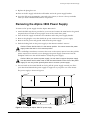
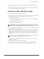
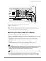
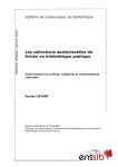
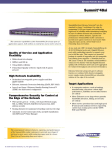
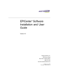
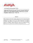
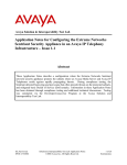
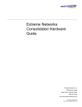
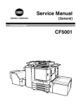
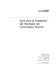
Alpine DC Power Supply Installation
Notes
Overview
These installation notes describe the Alpine™ DC power supplies, list the steps required to
prepare the power supplies and the cabling, and list the steps required to remove and replace a
power supply.
The Alpine chassis accommodates two power supplies. There are two types of power supplies
available: AC and DC. Both installed power supplies must be of the same type. This document
describes DC power supply installation.
Caution: Service to Alpine power supplies should be performed by trained service
personnel only. Before installing or removing any components of the system, or before
carrying out any maintenance procedures, read the safety information provided in
Appendix A of the Extreme Networks Consolidated Hardware Guide.
DC power supplies operate with DC input ranging from -40 to -70 V. These power supplies are
fully fault tolerant and load-sharing, so that if one power supply fails, the other power supply
will provide sufficient power to operate a fully loaded chassis. They are also hot-swappable, so
you can add a second power supply without powering off the chassis.
Caution: The Alpine chassis must be grounded. Use the ground lug on the Alpine DC
power supplies. Additionally, you can use the grounding studs on the rear panel of the
chassis.
The front of the power supply provides status LEDs, described in Table 1.
Table 1: Alpine DC Power Supply LEDs
LED
Color
Indicates
DC OK
Green
Normal
Off
Unplugged or fault
Amber
Fault
Off
Normal
Service
Each power supply has four outputs that connect to the chassis. These four outputs provide
power for the entire chassis.
Part Number: 122007-00 Rev 05
1
Preparing the Power Supplies
Preparing the Power Supplies
To prepare the power supplies, you must ensure that the SMMi module is using the appropriate
version of ExtremeWare, and you must attach cabling to the supplied lugs.
BootROM 6.5 and ExtremeWare v6.1.5 Required
The Alpine SMMi module requires both BootROM 6.5 (or later) and ExtremeWare v6.1.5 (or
later) in order to recognize the DC power supplies.
You can obtain BootROM 6.5 and ExtremeWare v.6.1.5 via anonymous FTP at:
ftp://ftp.extremenetworks.com/ts/outgoing/private/
From that directory, do a “get” on:
ew615.zip
Selecting the Cabling
Use the following guidelines when selecting cabling for the DC power supplies:
• Each DC power supply requires 30 A at -40 VDC (or equivalent power between -40 and -70
VDC).
• For DC power and ground cables, use 8 AWG, high-strand-count wire cable (Alpine 3808) or
10 AWG, high-strand-count wire cable (Alpine 3804).
Attaching the Cabling
To attach the cable to the lugs, perform the following steps.
1 Strip 0.5 inches of insulation from the appropriate AWG, high strand-count cable.
2 Insert the cable into the cable lugs.
Caution: Ensure that no copper is visible between the lug and the cable insulation.
3 Tighten the cable retention screw, using a 1/4” or 5/16” flathead screwdriver, to 20 in-lbs of
torque. The cable retention screw is shown in Figure 1.
Cable retention screw
Cable retention screw
38 lugs
Figure 1: 2-stud -40 V and RTN lug, and 1-stud ground lug
Alpine DC Power Supply Installation Notes
2
Installing the Alpine 3804 Power Supply
Installing the Alpine 3804 Power Supply
To install a DC power supply in the Alpine 3804 switch:
1 Attach the ESD strap that is provided to your wrist and connect the metal end to the ground
receptacle that is located on the top-right corner of the switch front panel.
2 Ensure that the following is true:
— The power supply is oriented correctly using the text on the front of the power supply
— The ejector/injector lever is open
— The safety latch is in the remove position
— The breaker is in the off position
Caution: When you insert a power supply, use one hand to support the power supply
from the bottom and the other hand to hold the central handle on the front of the power
supply. Do not use just the ejector/injector lever to insert a power supply.
3 Use the central handle to guide the power supply into the bay while supporting the supply
from the bottom with your other hand.
4 Place both hands on each side of the power supply to slowly and evenly slide the power
supply into the bay. During the last inch of insertion into the chassis, place one hand on the
central handle to steady the power supply and use your other hand to gently push the
ejector/injector lever towards the power supply to engage the power supply backplane
connectors.
Caution: Do not slam the power supply into the backplane. This or other excessive force
will cause damage and possibly require the return of the chassis.
5 Secure the power supply by tightening the screw on the ejector/injector lever using a #2
Phillips screwdriver.
6 Slide the locking latch away from the remove position.
7 Remove the plexiglas cover that shields the power connection on the power supply.
8 Attach the DC power and ground cables to the power supply, as shown in Figure 2.
45022
WHEN IN
RTN
OFF
-48V
ON
45022
SLIDE TO
REMOVE
38_lugs4
Figure 2: Alpine 3804 DC power supply with cables attached
Alpine DC Power Supply Installation Notes
3
Removing the Alpine 3804 Power Supply
9 Replace the plexiglas cover.
10 Turn on the DC supply at both the wall breaker and at the power supply breaker.
11 Leave the ESD strap permanently connected to the chassis, so that it is always available
when you need to handle ESD-sensitive components.
Removing the Alpine 3804 Power Supply
To remove a DC power supply from the Alpine 3804 switch:
1 Attach the ESD strap that is provided to your wrist and connect the metal end to the ground
receptacle that is located on the top-right corner of the switch front panel.
2 Turn off the DC supply at both the source breaker and at the power supply breaker.
3 Remove the plexiglas cover that shields the power connection on the power supply.
4 Remove the DC power and ground cables from the power supply.
5 Slide the locking latch on the power supply in the direction marked “remove.”
Caution: Ensure that the latch is in the remove position. You cannot remove the power
supply unless the latch is in the remove position.
6 Use a #2 Phillips screwdriver to unscrew the screw on the ejector/injector lever then pull the
ejector/injector lever towards you to disengage the power supply connections from the
backplane. Hold on to the central handle to steady the power supply.
Caution: When you remove a power supply, use one hand to support the power supply
from the bottom and the other hand to hold the central handle on the front of the power
supply. Do not use just the ejector/injector lever to remove a power supply.
7 Use one hand on the central handle to slowly pull the power supply towards you. Place
your other hand beneath the power supply to support it as you pull it out of the chassis.
The power supply is shown in Figure 3.
DC OK
45022
DC OK
WHEN INSTALLED IN 3804 THIS WAY UP
WHEN INSTALLED IN 3808 THIS WAY UP
SERVICE
OFF
ON
RTN
-48V
45022
SLIDE TO
REMOVE
38_DCPS4
Figure 3: Removing an Alpine 3804 DC power supply
Alpine DC Power Supply Installation Notes
4
Installing the Alpine 3808 Power Supply
8 If you are going to install a replacement power supply, follow the installation steps on
page -3.
9 Leave the ESD strap permanently connected to the chassis, so that it is always available
when you need to handle ESD-sensitive components.
Installing the Alpine 3808 Power Supply
To install a DC power supply in the Alpine 3808 switch:
1 Attach the ESD strap that is provided to your wrist and connect the metal end to the ground
receptacle that is located on the top-right corner of the switch front panel.
2 Ensure that the following is true:
— The power supply is oriented correctly using the text on the front of the power supply
— The ejector/injector lever is open
— The safety latch is in the remove position
— The breaker is in the off position
Caution: When you insert a power supply, use one hand to support the power supply
from the bottom and the other hand to hold the central handle on the front of the power
supply. Do not use just the ejector/injector lever to insert a power supply.
3 Use the central handle to guide the power supply into the bay while supporting the supply
from the bottom with your other hand.
4 Place both hands on each side of the power supply to slowly and evenly slide the power
supply into the bay. During the last inch of insertion into the chassis, place one hand on the
central handle to steady the power supply and use your other hand to gently push the
ejector/injector lever towards the power supply to engage the power supply backplane
connectors.
Caution: Do not slam the power supply into the backplane. This or other excessive force
will cause damage and possibly require the return of the chassis.
5 Secure the power supply by tightening the screw on the ejector/injector lever using a #2
Phillips-head screwdriver.
6 Slide the locking latch away from the remove position.
7 Remove the plexiglas cover that shields the power connection on the power supply.
8 Attach the DC power and ground cables to the power supply, as shown in Figure 4.
Alpine DC Power Supply Installation Notes
5
Removing the Alpine 3808 Power Supply
45022
ON
-48V
OFF
RTN
SLIDE TO
REMOVE
WHEN INS
45022
38_lugs8
Figure 4: Alpine 3808 DC power supply with cables attached
9 Replace the plexiglas cover.
10 Turn on the DC supply at both the wall breaker and at the power supply breaker.
11 Leave the ESD strap permanently connected to the chassis, so that it is always available
when you need to handle ESD-sensitive components.
Removing the Alpine 3808 Power Supply
To remove a DC power supply from the Alpine 3808 switch:
1 Attach the ESD strap that is provided to your wrist and connect the metal end to the ground
receptacle that is located on the top-right corner of the switch front panel.
2 Turn off the DC supply at both the source breaker and at the power supply breaker.
3 Remove the plexiglas cover that shields the power connection on the power supply.
4 Remove the DC power and ground cables from the power supply.
5 Slide the locking latch on the power supply in the direction marked “remove.”
Caution: Ensure that the latch is in the “remove” position. You cannot remove the power
supply unless the latch is in the “remove” position.
6 Use a #2 Phillips screwdriver to unscrew the screw on the ejector/injector lever then pull the
ejector/injector lever towards you to disengage the power supply connections from the
backplane. Hold on to the central handle to steady the power supply.
Caution: When you remove a power supply, use one hand to support the power supply
from the bottom and the other hand to hold the central handle on the front of the power
supply. Do not use just the ejector/injector lever to remove a power supply.
7 Use one hand on the central handle to slowly pull the power supply towards you. Place
your other hand beneath the power supply to support it as you pull it out of the chassis.
Alpine DC Power Supply Installation Notes
6
Removing the Alpine 3808 Power Supply
The power supply is shown in Figure 5.
45022
SERVICE
WHEN INSTALLED IN 3808 THIS WAY UP
ON
-48V
OFF
RTN
SLIDE TO
REMOVE
ESD
wrist strap
connector
WHEN INSTALLED IN 3804 THIS WAY UP
45022
DC OK
DC OK
38_DCPS8
Figure 5: Removing an Alpine 3808 DC power supply
8 If you are going to install a replacement power supply, follow the installation steps on
page -5.
9 Leave the ESD strap permanently connected to the chassis, so that it is always available
when you need to handle ESD-sensitive components.
Alpine DC Power Supply Installation Notes
7