1
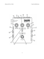
User Guide
WARNINGS
Use only with supplied power supply.
Avoid spilling liquids onto/into the unit.
Do not expose to excessive heat or moisture.
This equipment has been tested and found to comply with the limits for a Class B digital
device pursuant to Part 15 of FCC rules. Operation is subject to the following two
conditions: (1) This device may not cause harmful interference, and (2) this device must
accept any interference received, including interference that may cause undesired
operation.
Complete UG Part # 159037
Contents Part # 141226 Rev 1
Cover Part # 258259
Eventide is a registered trademarks of Eventide Inc.
Mixing Link is trademark of Manifold Labs, LLC.
©2013 Eventide Inc.
Mixing Link User Guide
Introduction
Contents
WARNINGS ............................................................................................. II
INTRODUCTION ..................................................................................... 3
CREATIVE USES ...................................................................................... 3
WEBSITE................................................................................................. 3
CONTROLS AND INDICATORS ............................................................ 4
INPUT GAIN KNOB ................................................................................ 5
GAIN BUTTON ........................................................................................ 5
PK LED.................................................................................................. 5
20 LED .................................................................................................. 5
MIX KNOB .............................................................................................. 5
MIX MODE TOGGLE SWITCH .................................................................. 6
PHONES & AMP LEVEL KNOB.............................................................. 6
FX LOOP FOOTSWITCH AND STATUS LED............................................... 6
HOLD/LATCH SWITCH........................................................................... 6
48V PHANTOM POWER SWITCH .......................................................... 7
48V PHANTOM LED ............................................................................. 7
PWR ON LED ........................................................................................ 7
GND LIFT BUTTON ................................................................................. 7
I/O CONNECTORS.................................................................................. 8
INPUTS ................................................................................................. 8
MIC/LINE IN Combo XLR Connector................................................. 8
INST IN ¼” Phonejack ....................................................................... 8
EFFECTS LOOP CONNECTIONS ....................................................... 8
TO FX ¼” Phonejack - Effects Send ................................................. 8
FROM FX ¼” Phonejack – Effects Return ......................................... 8
AUX 1/8” Phonejack – Connect to mobile device .............................. 8
OUTPUTS ............................................................................................. 9
TO AMP Phonejack............................................................................ 9
PHONES Phonejack .......................................................................... 9
DI/LINE OUT XLR Connector ............................................................ 9
PWR Jack .......................................................................................... 9
UNDER THE COVER ............................................................................ 10
9V BATTERY ...................................................................................... 10
TAILS ON/OFF .................................................................................... 10
SPECIFICATIONS ................................................................................. 11
1
BLOCK DIAGRAM ................................................................................ 12
LIMITED WARRANTY........................................................................... 13
2
Introduction
Mixing Link is a compact, high-quality Microphone (mic) Preamp with an Effects Loop for
easy and convenient patching of various audio between your mic (or instrument) and your
stompbox, mobile device, amp, console, and computer interface. Mixing Link can be used
in many ways to fit into virtually any audio setup. Mixing Link has been designed to be
equally at home on the pedal board, desktop and in studio and live environment.
Mixing Link boasts 65dB of gain and works with dynamic and ribbon mics. It also supports
condenser mics with its built-in 48V phantom power supply.
Mixing Link provides a variety of connections for pro and instrument
(balanced/unbalanced) levels, and an Auxiliary Mix connector and a headphone amp for
monitoring. A detailed description of the controls and input/output connectors follows.
Creative Uses
There are many creative and practical applications in which the Mixing Link can excel. In
addition to being a stellar microphone preamplifier, it can be used with a plethora of
connections for DI, re-amping, headphone monitoring, signal level matching, or mixing and
interfacing solutions.
Mixing Link allows easy connection of any microphone, instrument or line inputs to
any/many destinations. For instance, you can connect balanced line level outputs to guitar
amps and mics to balanced line level inputs simultaneously. You can also generate stereo
to mono summing and a stereo send output simultaneously. Using the headphone amp
output Mixing Link can also be used with your favorite stompbox as a practice amp or
vocal monitor.
Mixing Link is a problem solver and a creative tool and should be in every musicians’ and audio engineers’ toolbox. Please see separate Application Handbook for a complete list of Mixing Link application notes and connection diagrams.
Website
www.eventide.com is where you’ll find versions of this User Guide in other languages, FAQs, information on accessories, and updated documentation.
3
Mixing Link User Guide
Controls and Indicators
4
Mixing Link User Guide
Controls and Indicators
Controls and Indicators
(1) INPUT GAIN Knob
Sets the gain for Mixing Link’s microphone pre-amp. The total gain range available on the
INPUT GAIN knob depends on the connector the signal is attached to and the setting of
the GAIN button located on the right side of the Mixing Link, just above the “INST IN” jack. Each input connector yields different ranges for the INPUT GAIN knob. The following table
lists the gain range for each input and setting for the GAIN button:
INPUT
GAIN = HI
GAIN = LO
MIC XLR IN
+33 dB ~ +66 dB
+10 dB ~ +36 dB
LINE TRS IN
+9 dB ~ +42 dB
-14 dB ~ +12 dB
INSTRUMENT IN
+14 dB ~ +47 dB
-9 dB ~ +17 dB
The output level at the “TO FX” (SEND) jack is controlled by the INPUT GAIN knob.
(2) GAIN Button
Located on the right side of Mixing Link next to the “INST IN” jack, the GAIN button changes the total gain range of the Input Gain knob by ~22dB.
Button In = LO gain. Line level signals (keyboards, bass).
Button Out = HI gain. Microphones, electric guitars and other low output instruments.
Don’t be afraid to try the two gain settings for different types of inputs, Mixing Link’s inputs are well protected.
(3) Signal ‘PK’ LED and ‘-20’ LED
Below and to the right of the INPUT GAIN knob, the red PK LED lights when the output
signal of the MIC pre-amp hits the peak of its full-range, just before the MIC pre-amp stage
clips. It is fine if the PK LED lights on your loudest notes.
Located just below the PK LED, the green -20 LED lights when input signal is ~20 dB
below the MIC pre-amp’s full-scale output.
(4) MIX Knob
Varies the balance between the MIC/LINE IN and INST IN Dry signal and the “FROM FX” Return signal. As you turn MIX clockwise, the level of the FX Return signal always
increases. The effect of the MIX knob on the DRY signal level depends on the setting of
the MIX MODE Toggle Switch located just below the MIX knob.
5
Mixing Link User Guide
Controls and Indicators
(5) MIX MODE Toggle Switch
This three-position switch determines how the DRY and FX Return signals interact when
turning the MIX knob.
The DRY signal is the signal at the output of the MIC pre-amp stage. The source for the
DRY signal comes from either the MIC/LINE IN XLR connector or the INST IN ¼” phone jack.
The FX Return comes from the “FROM FX” (RETURN) phone jack. The three MIX switch modes are as follows:
DRY+FX:
The level of the DRY signal is fixed; the level of the FX
Return signal increases as you turn the MIX knob
clockwise. DRY+FX keeps your microphone or instrument
level fixed while you dial in just the right amount of FX
Return.
MIX:
The MIX knob acts like a wet/dry control. With the MIX knob
at full counter-clockwise, you will hear only the DRY signal.
At full clockwise, you will hear only the FX Return. Turn the
MIX knob to balance the two signals to taste.
FX ONLY:
The DRY signal is muted, you will not hear your
microphone, line or instrument input while the FX Loop is
engaged. The MIX knob acts like a volume control for the
FX Return signal. As you turn MIX knob clockwise, the FX
Return level increases.
(6) PHONES & AMP LEVEL Knob
Sets the output level for the Mixing Link’s two main output jacks: “TO AMP” and “PHONES”. This knob controls the output level whether or not the FX Loop is engaged or bypassed.
(7) FX LOOP Footswitch and Status LED
The FX LOOP footswitch activates/deactivates the FX Loop connected between the “TO FX” and “FROM FX” jacks, allowing you to turn on or off your effects chain with the tap of a switch.
When the status LED located above the footswitch is lit, the FX Loop is activated, sending
your DRY signal out to the FX Send jack. When the status LED is off, the FX Loop is
deactivated and muted.
The FX LOOP footswitch can work as either a momentary or latching switch, the
HOLD/LATCH toggle switch above the footswitch changes its action.
(8) HOLD/LATCH Switch
This toggle switch, located just above the footswitch, changes the action of the FX Loop
footswitch - either latching or momentary.
When set to the LATCH position, the FX Loop status changes state upon pressing the
footswitch and remains in this new state until you press the footswitch again; releasing the
footswitch does not cause the FX Loop status to change.
6
Mixing Link User Guide
Controls and Indicators
In the HOLD position, the footswitch becomes a momentary switch: when you press down
and hold the footswitch, the FX Loop is activated (the status LED lights), upon releasing
the footswitch, the FX Loop is deactivated (the status LED shuts off). Remember, in HOLD
mode, you must push and hold the footswitch to activate the FX Loop.
(9) ‘48V PHANTOM’ POWER Switch
Located on the back panel of the Mixing Link, next to the PWR jack, the 3-Position toggle
switch both activates the Mixing Link’s 48V Phantom Power circuit and is the battery’s power switch when powered from a 9V battery. If powered from the AC Adapter, push the
switch up to the 48V position to enable phantom power; to disable phantom power, set the
switch to the OFF position. Push the switch down to the BATTERY setting to enable the
9V battery’s power;; set the switch to the middle OFF position to disconnect the battery and
power down the unit.
The Mixing Link supplies phantom power only when a 9VDC AC Adapter powers the
pedal; it cannot provide phantom power when run from a 9V battery. The OFF position for
the 48V toggle switch both disables phantom power and disconnects the 9V battery from
the circuit. When you power the Mixing Link from an AC Adapter, power is always applied
to the pedal no matter the setting of the 48V toggle switch. Inserting a 9VDC AC Adapter
plug into the power jack disconnects the battery from the circuit; the BATTERY position on
the toggle switch is ignored.
(10) ‘48V PHANTOM’ LED This orange LED lights when phantom power is active. The 48V PHANTOM LED is
powered directly from phantom power thereby indicating that phantom power is both
active and working correctly. It is normal for some microphones to draw more current from
phantom power and cause this LED to dim.
(11) PWR ON LED
This green LED lights whenever Mixing Link is powered up. It illuminates when receiving
power from either the AC Adapter or 9V battery.
(12) GND LIFT Button
Connects or disconnects GND (ground) from pin 1 of the DI/LINE OUT XLR connector.
Button OUT: Pin 1 of the XLR connector connected to the Mixing Link’s GND.
Button IN: Pin 1 of the XLR connector is disconnected/lifted from GND. Pin 1 is floating in
the LIFT position.
Note:
Normally it is best to leave pin 1 connected to GND but if you hear hum (buzzing) and you
are using the DI/LINE OUT connector, try lifting the GND from the connector. Doing so
may help eliminate ground loops.
7
Mixing Link User Guide
I/O Connectors
I/O Connectors
INPUTS
(13) MIC/LINE IN Combo XLR Connector
MIC/ LINE IN connects directly to the MIC pre-amp gain stage. This combo connector
accepts balanced signals on either an XLR connector or ¼” TRS (Tip/Ring/Sleeve) plug.
The XLR connector is best suited for microphones whereas the ¼” input is best for line level inputs. Signals at the XLR connector have the most available gain while the ¼” Line input has the most headroom (to accommodate Line Level amplitude).
We recommend you always connect balanced signals to the MIC/LINE IN connector.
When connecting an unbalanced signal to the MIC pre-amp, we recommend using the
INST IN ¼” jack. The XLR connector is not suited for unbalanced signals. Note: Phantom power is applied to the XLR input, not the ¼” jack.
(14) INST IN ¼” Phonejack Use the high impedance (Hi-Z) INST IN jack to connect instruments, and other
unbalanced signals.
When you insert a plug into the INST IN jack the input to the MIC pre-amp is mixed with
the MIC/LINE input and the GAIN control act on both INST and MIC/LINE inputs
simultaneously.
EFFECTS LOOP CONNECTIONS
(15) TO FX ¼” Phonejack - Effects Send
A balanced/unbalanced output capable of connecting to a wide range of devices from
effects pedals to rack systems or just about anything with an audio input. The signal sent
out of “TO FX” comes directly from the MIC pre-amp gain stage; the output level of the
effects send can therefore be controlled with the INPUT GAIN knob. When the FX Loop is
deactivated (FX LOOP LED is off), “TO FX” send is muted.
(16) FROM FX ¼” Phonejack – Effects Return
A balanced/unbalanced input with capable of connecting to a wide range of devices from
effects pedals to rack systems. The input signal at the “FROM FX” jack is the FX signal for the MIX knob.
(17) AUX 1/8” Phonejack – Connect to mobile device
The “AUX” jack is a bi-directional connector on a four conductor (TRRS) 1/8” mini phone
jack for connecting to mobile devices. It sends out the mono “TO FX” send signal and receives back a stereo signal. The stereo return remains stereo for the PHONES output
but is converted to mono for the “TO AMP” and “DI/LINE OUT” outputs. The source device (the mobile device) controls the volume of the signal into the AUX
connector thereby controlling its volume in the mix with the MIC pre-amp output and the
FX Return.
8
Mixing Link User Guide
I/O Connectors
The “AUX” jack enables you to use your mobile device as an effects processor while
keeping the rest of your effects chain signal path intact. It also allows Mixing Link to serve
as an audio interface for recording directly into your mobile device. The “AUX” connector also allows for stereo playback of audio from an external source to be mixed with your mic
or instrument.
OUTPUTS
(18) TO AMP Phonejack
Unbalanced mono output for connecting the Mixing Link to a guitar amp, another effects
pedal, or to any input that accepts an unbalanced ¼” plug. When the FX Loop is active, the “TO AMP” signal originates at the output of the MIX knob. Deactivate the FX Loop and “TO AMP” outputs the MIC pre-amp directly.
The PHONES & AMP LEVEL knob always controls the output level at “TO AMP” whether or not the FX Loop is activated.
The AUX input signal is always sent to the “TO AMP” jack as a mono version of the stereo AUX signal.
(19) PHONES Phonejack
Stereo, powered version of the “TO AMP” output with the ability to drive headphones. The signal originates at the output of the MIX knob when the FX Loop is active; otherwise
it outputs the MIC pre-amp.
The PHONES & AMP LEVEL knob sets the volume level at the “PHONES” output at all times.
The stereo signal from the AUX jack is output in stereo to the “PHONES” jack at all times.
(20) DI/LINE OUT XLR Connector
The signal present at this XLR output is a balanced version of the “TO AMP” output except it bypasses the PHONES & AMP LEVEL knob.
Bypassing the LEVEL knob allows you to set your stage volume when connecting to the
“TO AMP” output without affecting the DI feed to the PA system. The output level is switchable between a low level DI output and a high level LINE output
using the small DIP switch located on the underside of Mixing Link. Set the DIP switch to
DI when connecting to an input that expects a MIC level signal; use the LINE setting when
connecting to a line level input. The factory default setting is LINE.
(21) PWR Jack
Insert the output plug from an AC Adapter into the PWR Jack. The plug must be center
negative 2.1mm and provide 200mA at 9VDC. The maximum allowable voltage that can
be connected to the PWR jack is 12VDC.
9
Mixing Link User Guide
Under The Cover
UNDER THE COVER
Removing Mixing Link’s bottom cover reveals two user accessible features: 9V Battery clip and Tails On/Off switch. When making changes to these two features, please do not touch
any other parts of the circuit board or you risk damaging your Mixing Link.
9V BATTERY
Mixing Link is capable of running from a standard 9V battery, we recommend alkaline. Set
the 48V switch to OFF to disconnect the battery from the circuit.
TAILS ON/OFF
Tails is the common term for an echo or delay’s repeats or the sound of your note decaying on a reverb effect.
Tails OFF: When the FX Loop is deactivated any reverb tail or delay repeats that the FX
Loop is producing will be muted immediately upon deactivating the FX Loop. Both “TO FX” output and “FROM FX” input are muted. Tails ON: A delay’s repeats or a reverb’s tail will continue to be audible upon disengaging the FX Loop. Although the “TO FX” output is immediately muted so no new audio goes out into the FX Loop when Tails is ON, the “FROM FX” input remains live and its signal is always present at the MIX knob.
If Tails is set to ON and the FX Loop is disengaged, turning the MIX knob will change the
volume of the “FROM FX” signal but it will not affect the MIC pre-amp’s output level, which remains at unity.
To change the Tails setting, remove the bottom cover of Mixing Link and flip the DIP
switch labeled SW6, located just above the footswitch. When set to the right direction
(towards “TO AMP”) Tails is set to ON. In the left direction (towards “INST IN”) Tails is set to OFF.
Tails Off is the factory default setting.
10
Mixing Link User Guide
Specifications
Specifications
Analog I/O
MAX I/P Levels, Input Impedance
INST IN
= +10dBu, 500kΩ XLR LINE IN
= +24dBu, 22kΩ
XLR MIC IN
= +4dBu, 2kΩ
FROM FX
= +10dB, 200kΩ
AUX IN
= +4dBu, 5.0kΩ
MAX O/P Levels, Output Impedance
TO FX
= +10dBu, 400Ω
TO AMP
= +10dBu, 250Ω
PHONES
= 150mW per channel, min Load = 8 Ohms
DI/LINE OUT
= (DI) -10dBu, (LINE) +18dBu, 200Ω
AUX OUT
= 18mV, 200Ω (mobile mic level)
Power Supply
9 VDC, 500 ma, center pin (-)
Minimum required current at 9VDC = 200mA
Dimensions
English: 3.6” (H) x 2.65” (W) x 1.5” (D)
Metric: 91 (H) x 67 (W) x 38 (D) mm
Weight
0.96 lb, 0.43 kG
Specifications subject to change without notice.
11
Mixing Link User Guide
Limited Warranty
Block Diagram
12
Mixing Link User Guide
Limited Warranty
LIMITED WARRANTY
Eventide products are built to exacting quality standards and should give years of troublefree service. If you are experiencing problems which are not cleared up or explained as
normal in the manual, your recourse is this warranty.
What the warranty does and does not cover
Eventide Inc. warrants the above-identified unit to be free from defects in workmanship
and material under normal operation and service for a period of one year from the date of
purchase, as detailed below. At our discretion within the warranty period, we may elect to
repair or replace the defective unit. This means that if the unit fails under normal
operation because of such defect, we will repair the defective unit at no charge for parts or
labor. We also assume a limited responsibility for shipping charges, as detailed below.
IN NO EVENT WILL WE BE RESPONSIBLE FOR CONSEQUENTIAL OR INCIDENTAL
DAMAGES CAUSED BY ANY DEFECT, AND SUCH DAMAGES ARE SPECIFICALLY
EXCLUDED FROM THIS WARRANTY. Our sole obligation is to repair or replace the
defective unit as described herein.
The warranty DOES NOT COVER any damage to the unit regardless of the cause of that
damage. The unit is a complex piece of equipment that does not react well to being
dropped, bounced, crushed, soaked or exposed to excessively high temperatures,
voltages, electrostatic or electromagnetic fields. If the unit is damaged for these or other
causes, and the unit is deemed to be economically repairable, we will repair it and charge
our normal rates.
The warranty DOES NOT COVER shipping damage, either to or from Eventide.
Who is covered under the warranty
The warranty applies to the original purchaser of a new unit from Eventide or an
Authorized Eventide Dealer. It is your responsibility to prove or to be able to prove that
you have purchased the unit under circumstances which affect the warranty. A copy of
your purchase invoice is normally necessary and sufficient for this.
Units with the serial number plate defaced or removed will not be serviced or covered by
this warranty.
When the warranty becomes effective
The one-year warranty period begins on the day the unit is purchased from an Authorized
Eventide Dealer or, if the unit is drop-shipped from Eventide, on the day shipped, plus a
reasonable allowance for shipping delays. This applies whether or not you return your
warranty registration form.
Who performs warranty work
The only company authorized to perform work under this warranty is Eventide Inc., Little
Ferry, New Jersey. While you are free to give authorization to anyone else (or to work on
it yourself), we will not honor claims for payment for parts or labor from you or from third
parties.
Shipping within the 50 United States
13
Mixing Link User Guide
Limited Warranty
You are responsible for getting the unit to our door at no cost to us. We cannot accept
collect or COD shipments. We will return the unit to you prepaid, at our expense, using an
expeditious shipping method, normally United Parcel Service.
Shipping outside the 50 United States
If you purchased the unit from a dealer in your country, consult with the dealer before
returning the unit. If you wish to return the unit to us, please note the following:
1. The unit must be prepaid to our door. This means that you are responsible
for all shipping charges, including customs brokerage and duties. When a unit is shipped
to us it must be cleared through United States Customs by an authorized broker. You
must make arrangements for this to be done. Normally, your freight forwarder has a
branch in the United States which can handle this transaction.
2. All shipments will be returned to you collect. If this is impossible because of
shipping regulations or money is due us, we will request prepayment from you for the
appropriate amount. If you nominate a freight carrier, we reserve the right to select a
substitute if necessary.
This warranty gives you specific legal rights and you may also have other rights which
vary from location to location.
(c) 2013, Eventide, Inc.
14