1
W5.0
Assembler and Preprocessor Manual
Revision 3.2, March 2009
Part Number:
82-000420-04
Analog Devices, Inc.
One Technology Way
Norwood, Mass. 02062-9106
a
Copyright Information
© 2009 Analog Devices, Inc., ALL RIGHTS RESERVED. This document may not be reproduced in any form without prior, express written
consent from Analog Devices, Inc.
Printed in the USA.
Disclaimer
Analog Devices, Inc. reserves the right to change this product without
prior notice. Information furnished by Analog Devices is believed to be
accurate and reliable. However, no responsibility is assumed by Analog
Devices for its use; nor for any infringement of patents or other rights of
third parties which may result from its use. No license is granted by implication or otherwise under the patent rights of Analog Devices, Inc.
Trademark and Service Mark Notice
The Analog Devices logo, VisualDSP++, Blackfin, SHARC, and TigerSHARC are registered trademarks of Analog Devices, Inc.
All other brand and product names are trademarks or service marks of
their respective owners.
CONTENTS
PREFACE
Purpose ......................................................................................... xiii
Intended Audience ........................................................................ xiii
Manual Contents ........................................................................... xiv
What’s New in this Manual ............................................................ xiv
Technical or Customer Support ....................................................... xv
Supported Processors ...................................................................... xvi
Product Information ...................................................................... xvi
Analog Devices Web Site .......................................................... xvi
VisualDSP++ Online Documentation ...................................... xvii
Technical Library CD ............................................................. xviii
Notation Conventions .................................................................. xviii
ASSEMBLER
Assembler Guide ........................................................................... 1-2
Assembler Overview ................................................................ 1-3
Writing Assembly Programs ..................................................... 1-4
Program Content ................................................................ 1-6
Assembly Instructions ..................................................... 1-6
VisualDSP++ 5.0 Assembler and Preprocessor Manual
iii
CONTENTS
Assembler Directives ....................................................... 1-6
Preprocessor Commands ................................................. 1-7
Program Structure .............................................................. 1-7
Code File Structure for SHARC Processors .................... 1-10
LDF for SHARC Processors .......................................... 1-10
Code File Structure for TigerSHARC Processors ............ 1-13
LDF for TigerSHARC Processors .................................. 1-13
Code File Structure for Blackfin Processors .................... 1-17
LDF for Blackfin Processors .......................................... 1-18
Program Interfacing Requirements .................................... 1-20
Using Assembler Support for C Structs .................................. 1-21
Preprocessing a Program ........................................................ 1-24
Using Assembler Feature Macros ........................................... 1-25
-D__VISUALDSPVERSION__ Predefined Macro ............ 1-31
Generating Make Dependencies ............................................ 1-33
Reading a Listing File ............................................................ 1-34
Enabling Statistical Profiling for Assembly Functions ............. 1-35
Assembler Syntax Reference ........................................................ 1-37
Assembler Keywords and Symbols ......................................... 1-38
Assembler Expressions ........................................................... 1-50
Assembler Operators ............................................................. 1-51
Numeric Formats .................................................................. 1-56
Representation of Constants in Blackfin ............................ 1-56
Fractional Type Support .................................................... 1-57
iv
VisualDSP++ 5.0 Assembler and Preprocessor Manual
CONTENTS
1.31 Fracts .................................................................... 1-58
1.0r Special Case ........................................................... 1-59
Fractional Arithmetic .................................................... 1-59
Mixed Type Arithmetic ................................................. 1-59
Comment Conventions ......................................................... 1-60
Conditional Assembly Directives ............................................ 1-60
C Struct Support in Assembly Built-In Functions ................... 1-63
OFFSETOF Built-In Function .......................................... 1-63
SIZEOF Built-In Function ................................................ 1-63
Struct References ................................................................... 1-64
Assembler Directives .............................................................. 1-67
.ALIGN, Specify an Address Alignment ............................. 1-72
.ALIGN_CODE, Specify an Address Alignment ................ 1-74
.ASCII .............................................................................. 1-76
.BYTE, Declare a Byte Data Variable or Buffer .................. 1-77
ASCII String Initialization Support ............................... 1-79
.COMPRESS, Start Compression ...................................... 1-81
.EXTERN, Refer to a Globally Available Symbol ............... 1-82
.EXTERN STRUCT, Refer to a Struct Defined Elsewhere . 1-83
.FILE, Override the Name of a Source File ........................ 1-85
.FILE_ATTR, Create an Attribute in the Object File ......... 1-86
.FORCECOMPRESS, Compress the Next Instruction ....... 1-87
.GLOBAL, Make a Symbol Available Globally ................... 1-88
.IMPORT, Provide Structure Layout Information .............. 1-90
VisualDSP++ 5.0 Assembler and Preprocessor Manual
v
CONTENTS
.INC/BINARY, Include Contents of a File ........................ 1-92
.LEFTMARGIN, Set the Margin Width of a Listing File ... 1-93
.LIST/.NOLIST, Listing Source Lines and Opcodes .......... 1-94
.LIST_DATA/.NOLIST_DATA, Listing Data Opcodes ..... 1-95
.LIST_DATFILE/.NOLIST_DATFILE, Listing Data
Initialization Files ........................................................ 1-96
.LIST_DEFTAB, Set the Default Tab Width for Listings ... 1-97
.LIST_LOCTAB, Set the Local Tab Width for Listings ...... 1-99
.LIST_WRAPDATA/.NOLIST_WRAPDATA ................ 1-100
.LONG, Defines and initializes 4-byte data objects .......... 1-101
.MESSAGE, Alter the Severity of an Assembler Message .. 1-102
.NEWPAGE, Insert a Page Break in a Listing File ............ 1-106
.NOCOMPRESS, Terminate Compression ..................... 1-107
.PAGELENGTH, Set the Page Length of a Listing File .... 1-108
.PAGEWIDTH, Set the Page Width of a Listing File ....... 1-109
.PORT, Legacy Directive ................................................. 1-111
.PRECISION, Select Floating-Point Precision ................. 1-112
.PREVIOUS, Revert to the Previously Defined Section ... 1-114
.PRIORITY, Allow Prioritized Symbol Mapping in Linker 1-115
Linker Operation ........................................................ 1-116
.REFERENCE, Provide Better Info in an X-REF File ...... 1-118
.RETAIN_NAME, Stop Linker from Eliminating Symbol 1-118
.ROUND_, Select Floating-Point Rounding .................... 1-119
.SECTION, Declare a Memory Section .......................... 1-122
Common .SECTION Attributes ................................. 1-122
vi
VisualDSP++ 5.0 Assembler and Preprocessor Manual
CONTENTS
DOUBLE* Qualifiers .................................................. 1-123
TigerSHARC-Specific Qualifiers .................................. 1-124
SHARC-Specific Qualifiers .......................................... 1-125
Initialization Section Qualifiers ................................... 1-126
.SEGMENT and .ENDSEG, Legacy Directives ............... 1-128
.SEPARATE_MEM_SEGMENTS ................................... 1-128
.SET, Set a Symbolic Alias ............................................... 1-129
.SHORT, Defines and initializes 2-byte data objects ......... 1-129
.STRUCT, Create a Struct Variable ................................. 1-130
.TYPE, Change Default Symbol Type .............................. 1-134
.VAR, Declare a Data Variable or Buffer .......................... 1-135
.VAR and ASCII String Initialization Support .............. 1-138
.WEAK, Support Weak Symbol Definition and Reference 1-140
Assembler Command-Line Reference ......................................... 1-141
Running the Assembler ........................................................ 1-142
Assembler Command-Line Switch Descriptions .................... 1-144
-align-branch-lines .......................................................... 1-149
-anomaly-detect [id1[,id2...]] .......................................... 1-149
-anomaly-warn {id1[,id2]|all|none} .................................. 1-149
-anomaly-workaround [id] .............................................. 1-150
-char-size-8 ..................................................................... 1-151
-char-size-32 ................................................................... 1-151
-char-size-any .................................................................. 1-151
-default-branch-np .......................................................... 1-151
VisualDSP++ 5.0 Assembler and Preprocessor Manual
vii
CONTENTS
-default-branch-p ........................................................... 1-152
-Dmacro[=definition] ..................................................... 1-152
-double-size-32 ............................................................... 1-152
-double-size-64 ............................................................... 1-153
-double-size-any ............................................................. 1-153
-expand-symbolic-links ................................................... 1-153
-expand-windows-shortcuts ............................................. 1-154
-file-attr attr[=val] .......................................................... 1-154
-flags-compiler ................................................................ 1-154
User-Specified Defines Options ................................... 1-155
Include Options ......................................................... 1-155
-flags-pp -opt1 [,-opt2...] ............................................... 1-156
-g ................................................................................... 1-156
WARNING ea1121: Missing End Labels ..................... 1-157
-h[elp] ............................................................................ 1-158
-i .................................................................................... 1-158
-l filename ...................................................................... 1-159
-li filename ..................................................................... 1-159
-M ................................................................................. 1-160
-MM .............................................................................. 1-160
-Mo filename .................................................................. 1-161
-Mt filename .................................................................. 1-161
-micaswarn ..................................................................... 1-161
-no-source-dependency ................................................... 1-161
viii
VisualDSP++ 5.0 Assembler and Preprocessor Manual
CONTENTS
-no-anomaly-detect [id1[,id2...]] ..................................... 1-162
-no-anomaly-workaround [id1[,id2...]] ............................ 1-162
-no-expand-symbolic-links .............................................. 1-162
-no-expand-windows-shortcuts ........................................ 1-163
-no-temp-data-file ........................................................... 1-163
-normal-word-code or -nwc ............................................. 1-163
-o filename ..................................................................... 1-164
-pp ................................................................................. 1-164
-proc processor ................................................................ 1-164
-save-temps ..................................................................... 1-165
-short-word-code or -swc ................................................. 1-165
-si-revision version .......................................................... 1-165
-sp .................................................................................. 1-166
-stallcheck ....................................................................... 1-166
-swc-exclude name1[,name2] ........................................... 1-167
-v[erbose] ....................................................................... 1-167
-version .......................................................................... 1-167
-w ................................................................................... 1-167
-Werror number[,number] .............................................. 1-168
-Winfo number[,number] ............................................... 1-168
-Wno-info ...................................................................... 1-168
-Wnumber[,number] ....................................................... 1-168
-Wsuppress number[,number] ......................................... 1-169
-Wwarn number[,number] .............................................. 1-169
VisualDSP++ 5.0 Assembler and Preprocessor Manual
ix
CONTENTS
-Wwarn-error ................................................................. 1-169
Specifying Assembler Options in VisualDSP++ .................... 1-170
PREPROCESSOR
Preprocessor Guide ....................................................................... 2-2
Writing Preprocessor Commands ............................................. 2-3
Header Files and #include Command ...................................... 2-4
System Header Files ............................................................ 2-5
User Header Files ............................................................... 2-5
Sequence of Tokens ............................................................ 2-6
Include Path Search ............................................................ 2-7
Writing Macros ....................................................................... 2-7
Macro Definition and Usage Guidelines .............................. 2-9
Examples of Multi-Line Code Macros with Arguments ...... 2-12
Debugging Macros ........................................................... 2-13
Using Predefined Preprocessor Macros ................................... 2-15
-D__VISUALDSPVERSION____ Predefined Macro (Preprocessor)
2-21
Specifying Preprocessor Options ............................................ 2-21
Preprocessor Command Reference ............................................... 2-22
Preprocessor Commands and Operators ................................. 2-22
#define ............................................................................. 2-24
Variable-Length Argument Definitions .......................... 2-25
#elif ................................................................................. 2-27
#else ................................................................................. 2-28
x
VisualDSP++ 5.0 Assembler and Preprocessor Manual
CONTENTS
#endif ............................................................................... 2-29
#error ............................................................................... 2-30
#if .................................................................................... 2-31
#ifdef ................................................................................ 2-32
#ifndef .............................................................................. 2-33
#include ........................................................................... 2-34
#line ................................................................................. 2-36
#pragma ........................................................................... 2-37
#undef .............................................................................. 2-38
#warning .......................................................................... 2-39
# (Argument) .................................................................... 2-40
## (Concatenate) .............................................................. 2-42
? (Generate a unique label) ................................................ 2-43
Preprocessor Command-Line Reference ....................................... 2-45
Running the Preprocessor ...................................................... 2-45
Preprocessor Command-Line Switches ................................... 2-46
-cpredef ............................................................................ 2-48
-cs! ................................................................................... 2-49
-cs/* .................................................................................. 2-49
-cs// .................................................................................. 2-50
-cs{ ................................................................................... 2-50
-csall ................................................................................. 2-50
-Dmacro[=def ] ................................................................. 2-50
-h[elp] .............................................................................. 2-50
VisualDSP++ 5.0 Assembler and Preprocessor Manual
xi
CONTENTS
-i ...................................................................................... 2-51
-i ...................................................................................... 2-51
-I- .................................................................................... 2-52
-M ................................................................................... 2-53
-MM ................................................................................ 2-53
-Mo filename .................................................................... 2-53
-Mt filename .................................................................... 2-54
-o filename ....................................................................... 2-54
-stringize .......................................................................... 2-54
-tokenize-dot .................................................................... 2-54
-Uname ............................................................................ 2-55
-v[erbose] ......................................................................... 2-55
-version ............................................................................ 2-55
-w .................................................................................... 2-55
-Wnumber ....................................................................... 2-56
-warn ............................................................................... 2-56
INDEX
xii
VisualDSP++ 5.0 Assembler and Preprocessor Manual
PREFACE
Thank you for purchasing Analog Devices, Inc. development software for
digital signal processing (DSP) applications.
Purpose
The VisualDSP++ 5.0 Assembler and Preprocessor Manual contains information about the assembler and preprocessor utilities for the following
Analog Devices, Inc. processor families—Blackfin® (ADSP-BFxxx),
SHARC® (ADSP-21xxx), and TigerSHARC® (ADSP-TSxxx) processors.
The manual describes how to write assembly programs for these processors
and provides reference information about related development software.
It also provides information on new and legacy syntax for assembler and
preprocessor directives and comments, as well as command-line switches.
Intended Audience
The primary audience for this manual is a programmer who is familiar
with Analog Devices processors. This manual assumes that the audience
has a working knowledge of the appropriate processor architecture and
instruction set. Programmers who are unfamiliar with Analog Devices
processors can use this manual, but should supplement it with other texts
(such as the appropriate hardware reference and programming reference
manuals) that describe your target architecture.
VisualDSP++ 5.0 Assembler and Preprocessor Manual
xiii
Manual Contents
Manual Contents
The manual consists of:
• Chapter 1, “Assembler”
Provides an overview of the process of writing and building
assembly programs. It also provides information about assembler
switches, expressions, keywords, and directives.
• Chapter 2, “Preprocessor”
Provides procedures for using preprocessor commands within
assembly source files as well as the preprocessor’s command-line
interface options and command sets.
What’s New in this Manual
This revision of the VisualDSP++ 5.0 Assembler and Preprocessor Manual
documents assembler and preprocessor functionality that is new to VisualDSP++® 5.0 and updates (up to update 6), including support for new
ADSP-2146x SHARC processors.
In addition, modifications and corrections based on errata reports against
the previous revision of the manual have been made.
xiv
VisualDSP++ 5.0 Assembler and Preprocessor Manual
Preface
Technical or Customer Support
You can reach Analog Devices, Inc. Customer Support in the following
ways:
• Visit the Embedded Processing and DSP products Web site at
http://www.analog.com/processors/technical_support
• E-mail tools questions to
[email protected]
• E-mail processor questions to
[email protected] (World wide support)
[email protected] (Europe support)
[email protected] (China support)
• Phone questions to 1-800-ANALOGD
• Contact your Analog Devices, Inc. local sales office or authorized
distributor
• Send questions by mail to:
Analog Devices, Inc.
One Technology Way
P.O. Box 9106
Norwood, MA 02062-9106
USA
VisualDSP++ 5.0 Assembler and Preprocessor Manual
xv
Supported Processors
Supported Processors
The assembler and preprocessor of VisualDSP++ 5.0 supports the following Analog Devices, Inc. processors.
• Blackfin (ADSP-BFxxx)
• SHARC (ADSP-21xxx)
• TigerSHARC (ADSP-TSxxx)
The majority of the information in this manual applies to all processors.
For a complete list of processors supported by VisualDSP++ 5.0, refer to
the online Help.
Product Information
Product information can be obtained from the Analog Devices Web site,
VisualDSP++ online Help system, and a technical library CD.
Analog Devices Web Site
The Analog Devices Web site, www.analog.com, provides information
about a broad range of products—analog integrated circuits, amplifiers,
converters, and digital signal processors.
To access a complete technical library for each processor family, go to
http://www.analog.com/processors/technical_library. The manuals
selection opens a list of current manuals related to the product as well as a
link to the previous revisions of the manuals. When locating your manual
title, note a possible errata check mark next to the title that leads to the
current correction report against the manual.
xvi
VisualDSP++ 5.0 Assembler and Preprocessor Manual
Preface
Also note, MyAnalog.com is a free feature of the Analog Devices Web site
that allows customization of a Web page to display only the latest information about products you are interested in. You can choose to receive
weekly e-mail notifications containing updates to the Web pages that meet
your interests, including documentation errata against all manuals. MyAnalog.com provides access to books, application notes, data sheets, code
examples, and more.
Visit MyAnalog.com to sign up. If you are a registered user, just log on.
Your user name is your e-mail address.
VisualDSP++ Online Documentation
Online documentation comprises the VisualDSP++ Help system, software
tools manuals, hardware tools manuals, processor manuals, Dinkum
Abridged C++ library, and FLEXnet License Tools documentation. You
can search easily across the entire VisualDSP++ documentation set for any
topic of interest.
For easy printing, supplementary Portable Documentation Format (.pdf)
files for all manuals are provided on the VisualDSP++ installation CD.
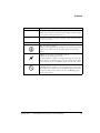
Each documentation file type is described as follows.
File
Description
.chm
Help system files and manuals in Microsoft help format
.htm or
.html
Dinkum Abridged C++ library and FLEXnet license tools software
documentation. Viewing and printing the .html files requires a browser, such as
Internet Explorer 6.0 (or higher).
.pdf
VisualDSP++ and processor manuals in PDF format. Viewing and printing the
.pdf files requires a PDF reader, such as Adobe Acrobat Reader (4.0 or higher).
VisualDSP++ 5.0 Assembler and Preprocessor Manual
xvii
Notation Conventions
Technical Library CD
The technical library CD contains seminar materials, product highlights,
a selection guide, and documentation files of processor manuals, VisualDSP++ software manuals, and hardware tools manuals for the following
processor families: Blackfin, SHARC, TigerSHARC, ADSP-218x, and
ADSP-219x.
To order the technical library CD, go to http://www.analog.com/processors/technical_library, navigate to the manuals page for your
processor, click the request CD check mark, and fill out the order form.
Data sheets, which can be downloaded from the Analog Devices Web site,
change rapidly, and therefore are not included on the technical library
CD. Technical manuals change periodically. Check the Web site for the
latest manual revisions and associated documentation errata.
Notation Conventions
Text conventions used in this manual are identified and described as
follows.
conventions, which apply only to specific chapters, may
L Additional
appear throughout this document.
xviii
Example
Description
Close command
(File menu)
Titles in in bold style reference sections indicate the location of an item
within the VisualDSP++ environment’s menu system (for example, the
Close command appears on the File menu).
{this | that}
Alternative required items in syntax descriptions appear within curly
brackets and separated by vertical bars; read the example as this or
that. One or the other is required.
[this | that]
Optional items in syntax descriptions appear within brackets and separated by vertical bars; read the example as an optional this or that.
VisualDSP++ 5.0 Assembler and Preprocessor Manual
Preface
Example
Description
[this,…]
Optional item lists in syntax descriptions appear within brackets
delimited by commas and terminated with an ellipse; read the example
as an optional comma-separated list of this.
.SECTION
Commands, directives, keywords, and feature names are in text with
letter gothic font.
filename
Non-keyword placeholders appear in text with italic style format.
L
a
[
Note: For correct operation, ...
A Note provides supplementary information on a related topic. In the
online version of this book, the word Note appears instead of this
symbol.
Caution: Incorrect device operation may result if ...
Caution: Device damage may result if ...
A Caution identifies conditions or inappropriate usage of the product
that could lead to undesirable results or product damage. In the online
version of this book, the word Caution appears instead of this symbol.
Warning: Injury to device users may result if ...
A Warning identifies conditions or inappropriate usage of the product
that could lead to conditions that are potentially hazardous for devices
users. In the online version of this book, the word Warning appears
instead of this symbol.
VisualDSP++ 5.0 Assembler and Preprocessor Manual
xix
Notation Conventions
xx
VisualDSP++ 5.0 Assembler and Preprocessor Manual
1 ASSEMBLER
This chapter provides information on how to use the assembler to develop
and assemble programs for SHARC (ADSP-21xxx), TigerSHARC
(ADSP-TSxxx), and Blackfin (ADSP-BFxxx) processors.
The chapter contains the following sections:
• “Assembler Guide” on page 1-2
Describes how to develop new programs using the processor’s
assembly language
• “Assembler Syntax Reference” on page 1-37
Provides the assembler rules and conventions of syntax used to
define symbols (identifiers), expressions, and to describe different
numeric and comment formats
• “Assembler Command-Line Reference” on page 1-141
Provides reference information on the assembler’s switches and
conventions
code examples in this manual have been compiled using
L The
VisualDSP++ 5.0 The examples compiled with other versions of
VisualDSP++ may result in build errors or different output
although the highlighted algorithms stand and should continue to
stand in future releases of VisualDSP++.
VisualDSP++ 5.0 Assembler and Preprocessor Manual
1-1
Assembler Guide
Assembler Guide
In VisualDSP++ 5.0, you can run the assembler drivers for each processor
family from the VisualDSP++ integrated debugging and development
environment (IDDE) or from an operating system command line The
assembler processes assembly source, data, and header files to produce an
object file. Assembler operations depend on two types of controls:
assembler directives and assembler switches.
VisualDSP++ 5.0 supports the following assembler drivers.
•
easm21k.exe
(for SHARC processors)
•
easmts.exe
•
easmblkfn.exe
(for TigerSHARC processors)
(for Blackfin processors)
This section describes how to develop new programs in the Analog
Devices processor assembly language. It provides information on how to
assemble your programs from the operating system’s command line.
Software developers using the assembler should be familiar with these
topics:
• “Writing Assembly Programs” on page 1-4
• “Using Assembler Support for C Structs” on page 1-21
• “Preprocessing a Program” on page 1-24
• “Using Assembler Feature Macros” on page 1-25
• “Generating Make Dependencies” on page 1-33
• “Reading a Listing File” on page 1-34
1-2
VisualDSP++ 5.0 Assembler and Preprocessor Manual
Assembler
• “Enabling Statistical Profiling for Assembly Functions” on
page 1-35
• “Specifying Assembler Options in VisualDSP++” on page 1-170
For information about a processor’s architecture, including the instruction
set used when writing assembly programs, refer to the Hardware Reference
and the Programming Reference for the appropriate processor.
Assembler Overview
The assembler processes data from assembly source (.asm), data (.dat),
and header (.h) files to generate object files in executable and linkable
format (ELF), an industry-standard format for binary object files. The
object file has a .doj extension.
In addition to the object file, the assembler can produce a listing file
(.lst) that shows the correspondence between the binary code and the
source.
Assembler switches are specified from the VisualDSP++ IDDE or from the
command line used to invoke the assembler. These switches allow you to
control the assembly process of source, data, and header files. Use these
switches to enable and configure assembly features, such as search paths,
output file names, and macro preprocessing. For more information, see
“Assembler Command-Line Reference” on page 1-141.
You can also set assembler options via the Assemble page of the Project
Options dialog box in VisualDSP++. For more information, see “Specifying Assembler Options in VisualDSP++” on page 1-170.
VisualDSP++ 5.0 Assembler and Preprocessor Manual
1-3
Assembler Guide
Writing Assembly Programs
Assembler directives are coded in assembly source files. The directives
allow you to define variables, set up hardware features, and identify program sections for placement within processor memory. The assembler uses
directives for guidance as it translates a source program into object code.
Write assembly language programs using the VisualDSP++ editor or any
editor that produces text files. Do not use a word processor that embeds
special control codes in the text. Use an .asm extension to source file
names to identify them as assembly source files.
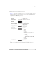
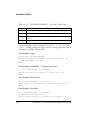
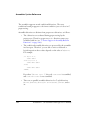
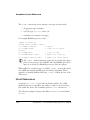
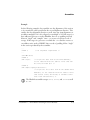
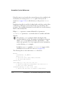
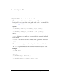
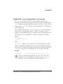
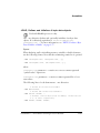
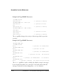
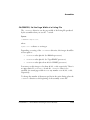
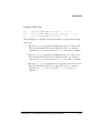
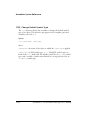
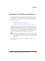
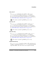
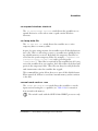
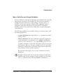
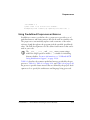
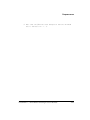
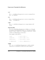
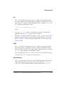
Figure 1-1 shows a graphical overview of the assembly process. The figure
shows the preprocessor processing the assembly source (.asm) and header
(.h) files.
Assemble your source files from the VisualDSP++ environment or using
any mechanism, such as a batch file or makefile, that supports invoking an
appropriate assembler driver with a specified command-line command.
By default, the assembler processes an intermediate file to produce a
binary object file (.doj) and an optional listing file (.lst).
Object files produced by the processor assembler may be used as input to
the linker and archiver. You can archive the output of an assembly process
into a library file (.dlb), which can then be linked with other objects into
an executable. Use the linker to combine separately assembled object files
and objects from library files to produce an executable file. For more
information about the linker and archiver, refer to the VisualDSP++ 5.0
Linker and Utilities Manual.
A binary object file (.doj) and an optional listing (.lst) file are final
results of the successful assembly.
The assembler listing file is a text file read for information on the results
of the assembly process. The listing file also provides information about
the imported C data structures. The listing file tells which imports were
used within the program, followed by a more detailed section. (See the
1-4
VisualDSP++ 5.0 Assembler and Preprocessor Manual
Assembler
Data initialization file
(.DAT)
Assembly source file
(.ASP)
Header file
(.H)
Preprocessor
Intermediate
preprocessed
file (.IS)
Assembler
Object file
(.OBJ)
Listing file
(.LST)
Figure 1-1. Assembler Input and Output Files
directive on page 1-90.) The file shows the name, total size, and
layout with offset for the members. The information appears at the end of
the listing. You must specify the -l switch (on page 1-159) to produce a
listing file.
.IMPORT
The assembly source file may contain preprocessor commands, such as
that cause the preprocessor to include header files (.h) into the
source program. The preprocessor’s only output, an intermediate source
file (.is), is the assembler’s primary input. In normal operation, the
preprocessor output is a temporary file that is deleted during the assembly
process.
#include,
VisualDSP++ 5.0 Assembler and Preprocessor Manual
1-5
Assembler Guide
Program Content
Assembly source file statements include assembly instructions, assembler
directives, and preprocessor commands.
Assembly Instructions
Instructions adhere to the processor’s instruction set syntax, which is
documented in the processor’s Programming Reference. Each instruction
line must be terminated by a semicolon (;). On TigerSHARC processors,
each instruction line (which can contain up to 4 instructions) is terminated by an additional semicolon (;;). Figure 1-2 on page 1-8 shows an
example assembly source file.
To mark the location of an instruction, place an address label at the beginning of an instruction line or on the preceding line. End the label with a
colon (:) before beginning the instruction. Your program can then refer to
this memory location using the label instead of an address. The assembler
places no restriction on the number of characters in a label.
Labels are case sensitive. The assembler treats “outer” and “Outer” as
unique labels. For example (in Blackfin processors),
outer: [I1] = R0;
Outer: R1 = 0X1234;
JUMP outer;
// jumps back 2 instructions
Assembler Directives
Assembler directives begin with a period (.) and end with a semicolon (;).
The assembler does not differentiate between directives in lowercase or
uppercase.
manual prints directives in uppercase to distinguish them
L This
from other assembly statements.
1-6
VisualDSP++ 5.0 Assembler and Preprocessor Manual
Assembler
For example (Blackfin processors):
.SECTION data1;
.BYTE2 sqrt_coeff[2] = 0x5D1D, 0xA9ED;
For a complete description of the assembler’s directive set, see “Assembler
Directives” on page 1-67.
Preprocessor Commands
Preprocessor commands begin with a pound sign (#) and end with a
carriage return. The pound sign must be the first non-white space
character on the line containing the command. If the command is longer
than one line, use a backslash (\) and a carriage return to continue the
command onto the next line.
Do not put any characters between the backslash and the carriage return.
Unlike assembler directives, preprocessor commands are case sensitive and
must be lowercase. For example,
#include "string.h"
#define MAXIMUM 100
For more information, see “Writing Preprocessor Commands” on
page 2-3. For a list of the preprocessor commands, see “Preprocessor
Command-Line Reference” on page 2-45.
Program Structure
An assembly source file defines code (instructions) and data. It also
organizes the instructions and data to allow the use of the linker description file (.ldf) to describe how code and data are mapped into the
memory on your target processor. The way you structure your code and
data into memory should follow the memory architecture of the target
processor.
VisualDSP++ 5.0 Assembler and Preprocessor Manual
1-7
Assembler Guide
Use the .SECTION directive to organize the code and data in assembly
source files. The .SECTION directive defines a grouping of instructions and
data that occupies contiguous memory addresses in the processor. The
name given in a .SECTION directive corresponds to an input section name
in the linker description file.
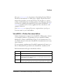
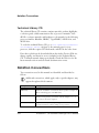
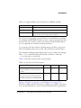
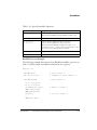
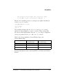
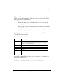
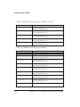
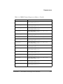
Table 1-1, Table 1-2, and Table 1-3 show suggested input section names
for data and code that can be used in your assembly source for various
processors. Using these predefined names in your sources makes it easier
to take advantage of the default .ldf file included in your DSP system.
However, you may also define your own sections. For information on
.ldf files, refer to the VisualDSP++ 5.0 Linker and Utilities Manual.
Table 1-1. Suggested Input Section Names for a SHARC .ldf File
.SECTION
Name
Description
seg_pmco
A section in program memory that holds code
seg_dmda
A section in data memory that holds data
seg_pmda
A section in program memory that holds data
seg_rth
A section in program memory that holds system initialization code
and interrupt service routines
seg_swco
A section in short word memory that holds instructions encoded for
execution from short word memory.
NOTE: Applies to the ADSP-2146x processors only.
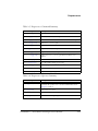
Table 1-2. Suggested Input Section Names for a TigerSHARC .ldf File
.SECTION
1-8
Name
Description
data1
A section that holds data in memory block M1
data2
A section that holds data in memory block M2 (specified with the
PM memory qualifier)
program
A section that holds code
VisualDSP++ 5.0 Assembler and Preprocessor Manual
Assembler
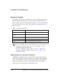
Table 1-3. Suggested Input Section Names for a Blackfin .ldf File
.SECTION
Name
Description
data1
A section that holds data
program
A section that holds code
constdata
A section that holds global data (which is declared as constant) and
literal constants such as strings and array initializers
Use sections in a program to group elements to meet hardware constraints.
For example, the ADSP-BF535 processor has a separate program and data
memory in Level 1 memory only. Level 2 memory and external memory
are not separated into instruction and data memory.
To group the code that resides in off-chip memory, declare a section for
that code and place that section in the selected memory with the linker.
The example assembly program defines three sections. Each section begins
with a .SECTION directive and ends with the occurrence of the next
.SECTION directive or end-of-file.
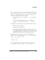
Table 1-4 lists the sections in the source program:
Table 1-4. Sections in Source Programs
Section
Blackfin
SHARC
TigerSHARC
Data Section
Variables and buffers are declared and can be
initialized
data1
constdata
seg_dmda
data1
data2
seg_pmco
program
Program Section
seg_rth
Data, instructions, and possibly other types of program
statements are in this section, including statements that are needed for conditional assembly
Figure 1-2, Figure 1-3 on page 1-14, and Figure 1-4 on page 1-17
describe assembly code file structure for each processor family. They show
how a program divides into sections that match the memory segmentation
VisualDSP++ 5.0 Assembler and Preprocessor Manual
1-9
Assembler Guide
of a DSP system. Notice that an assembly source may contain preprocessor commands (such as #include to include other files in source code),
#ifdef (for conditional assembly), or #define (to define macros). The
SECTIONS{} commands define the .SECTION placements in the system’s
physical memory as defined by the linker’s MEMORY{} command. Assembler
directives, such as .VAR (or .BYTE for Blackfin processors), appear within
sections to declare and initialize variables.
Code File Structure for SHARC Processors
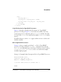
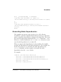
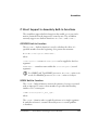
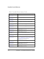
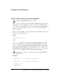
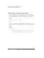
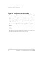
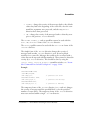
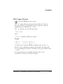
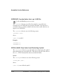
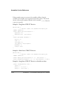
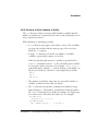
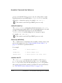
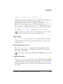
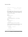
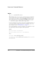
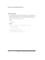
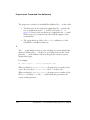
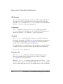
Figure 1-2 describes assembly code file structure for SHARC processors.
Looking at Figure 1-2, notice that the .PRECISION and .ROUND_ZERO
directives inform the assembler to store floating-point data with 40-bit
precision and to round a floating-point value to a closer-to-zero value if it
does not fit in the 40-bit format.
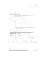
LDF for SHARC Processors
Listing 1-1 shows a sample user-defined .ldf file for SHARC processors.
Looking at the file’s SECTIONS{} command, notice that the INPUT_SECTION
commands map to the names of memory sections (such as program, data1,
data2, ctor, heaptab, and so on) used in the example assembly sample
program.
Listing 1-1. LDF Example for SHARC Processors
ARCHITECTURE(ADSP-21062)
SEARCH_DIR( $ADI_DSP\21k\lib )
$LIBRARIES = lib060.dlb, libc.dlb;
$OBJECTS = $COMMAND_LINE_OBJECTS, 060_hdr.doj;
MEMORY {
seg_rth {TYPE(PM RAM) START(0x20000) END(0x20fff) WIDTH(48)}
seg_init{TYPE(PM RAM) START(0x21000) END(0x2100f) WIDTH(48)}
seg_pmco{TYPE(PM RAM) START(0x21010) END(0x24fff) WIDTH(48)}
1-10
VisualDSP++ 5.0 Assembler and Preprocessor Manual
Assembler
Preprocessor Commands
Assembler Directives
.#include "const.h"
#define PI 3.14159
.PRECISION 40;
.ROUND_ZERO;
.SECTION/DM seg_dmda;
.VAR fxd[10] = 1,2,3,4,5,6,7,8,9,0xA;
.VAR rad;
Data Section
.SECTION/PM seg_pmda;
.VAR flt[5] = PI,PI/2,1.0,2.0,2.0/3.0;
Assembler Label
Code Section
.SECTION/PM seg_pmco;
/* instructions */
function1:
I0 = fxd;
M0 = 1;
I8 = flt;
M8 = 1;
R0 = LENGTH(flt);
LCNTR = R0, DO this_loop UNTIL LCE;
R0 = DM(I0,M0), R1 = PM(I8,M8);
R2 = FIX F1 BY R0;
this_loop:
R3 = R3 + R2;
DM(rad) = R3;
Preprocessor Commands
for Conditional Assembly
Assembler Label
#ifdef duplicate_write
DM(rad) = R3;
#endif
function1.end:
Figure 1-2. Assembly Code File Structure for SHARC Processors
seg_pmda{TYPE(DM RAM) START(0x28000) END(0x28fff) WIDTH(32)}
seg_dmda{TYPE(DM RAM) START(0x29000) END(0x29fff) WIDTH(32)}
seg_stak{TYPE(DM RAM) START(0x2e000) END(0x2ffff) WIDTH(32)}
/* memory declarations for default heap */
seg_heap{TYPE(DM RAM) START(0x2a000) END(0x2bfff) WIDTH(32)}
/* memory declarations for custom heap */
seg_heaq{TYPE(DM RAM) START(0x2c000) END(0x2dfff) WIDTH(32)}
}
// End MEMORY
VisualDSP++ 5.0 Assembler and Preprocessor Manual
1-11
Assembler Guide
PROCESSOR p0 {
LINK_AGAINST( $COMMAND_LINE_LINK_AGAINST)
OUTPUT( $COMMAND_LINE_OUTPUT_FILE )
SECTIONS {
.seg_rth {
INPUT_SECTIONS( $OBJECTS(seg_rth) $LIBRARIES(seg_rth))
} > seg_rth
.seg_init {
INPUT_SECTIONS( $OBJECTS(seg_init) $LIBRARIES(seg_init))
} > seg_init
.seg_pmco {
INPUT_SECTIONS( $OBJECTS(seg_pmco) $LIBRARIES(seg_pmco))
} > seg_pmco
.seg_pmda {
INPUT_SECTIONS( $OBJECTS(seg_pmda) $LIBRARIES(seg_pmda))
} > seg_pmda
.seg_dmda {
INPUT_SECTIONS( $OBJECTS(seg_dmda) $LIBRARIES(seg_dmda))
} > seg_dmda
.stackseg {
ldf_stack_space = .;
ldf_stack_length = 0x2000;
} > seg_stak
/* section placement for default heap */
.heap {
ldf_heap_space = .;
ldf_heap_end = ldf_heap_space + 0x2000;
ldf_heap_length = ldf_heap_end - ldf_heap_space;
} > seg_heap
/* section placement for additional custom heap */
1-12
VisualDSP++ 5.0 Assembler and Preprocessor Manual
Assembler
.heaq {
ldf_heaq_space = .;
ldf_heaq_end = ldf_heaq_space + 0x2000;
ldf_heaq_length = ldf_heaq_end - ldf_heaq_space;
} > seg_heaq
} // End SECTIONS
} // End P0
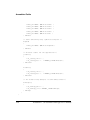
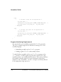
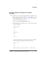
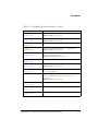
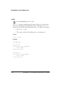
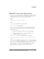
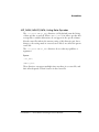
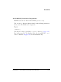
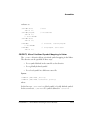
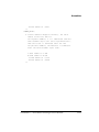
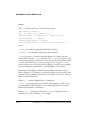
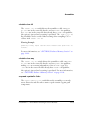
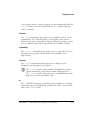
Code File Structure for TigerSHARC Processors
Figure 1-3 describes assembly code file structure for TigerSHARC
processors. Looking at Figure 1-3, notice that an assembly source may
contain preprocessor commands, such as #include (to include other files
in source code), #ifdef (for conditional assembly), or #define (to define
macros).
Assembler directives, such as .VAR, appear within sections to declare and
initialize variables.
LDF for TigerSHARC Processors
Listing 1-2 shows a sample user-defined .ldf file for TigerSHARC
processors. Looking at the file’s SECTIONS{} command, notice that the
INPUT_SECTION commands map to the names of memory sections (such as
program, data1, data2, ctor, heaptab, and so on) used in the example
assembly sample program.
Listing 1-2. Example Linker Description File for TigerSHARC Processors
ARCHITECTURE(ADSP-TS101)
SEARCH_DIR( $ADI_DSP\TS\lib )
$OBJECTS = $COMMAND_LINE_OBJECTS;
/* Internal memory blocks are 0x10000 (64k) */
MEMORY
VisualDSP++ 5.0 Assembler and Preprocessor Manual
1-13
Assembler Guide
.SECTION data1;
.VAR buffer1 [0x100] = 'buffer .dat.';
Data Section
Assembler Directive
Data Section
.SECTION data2;
.VAR buffer2;
Code Section
.SECTION program;
start:
Assembler Label
Preprocessor Commands
for Conditional Assembly
#ifdef XR0_SET_TO_2
xR0=0x2;;
#else
xR0=0x1;;
#endif
Assembly Instructions
J1 = buffer1;;
JL1 = 0;;
J2 = 1;;
LC0 = 0x100;;
this loop: [J+=J2] = XRO;;
IF NLCOE, JUMP this_loop;;
Figure 1-3. Assembly Code File Structure for TigerSHARC Processors
{
M0Code
{ TYPE(RAM) START(0x00000000) END(0x0000FFFF) WIDTH(32)
M1Data
{ TYPE(RAM) START(0x00080000) END(0x0008BFFF) WIDTH(32)
M1Heap
{ TYPE(RAM) START(0x0008C000) END(0x0008C7FF) WIDTH(32)
}
}
}
M1Stack { TYPE(RAM) START(0x0008C800) END(0x0008FFFF) WIDTH(32)
}
M2Data
{ TYPE(RAM) START(0x00100000) END(0x0010BFFF) WIDTH(32)
}
M2Stack { TYPE(RAM) START(0x0010C000) END(0x0010FFFF) WIDTH(32)
}
SDRAM
{ TYPE(RAM) START(0x04000000) END(0x07FFFFFF) WIDTH(32)
}
1-14
VisualDSP++ 5.0 Assembler and Preprocessor Manual
Assembler
MS0
{ TYPE(RAM) START(0x08000000) END(0x0BFFFFFF) WIDTH(32)
MS1
{ TYPE(RAM) START(0x0C000000) END(0x0FFFFFFF) WIDTH(32)
}
}
}
PROCESSOR p0
/* The processor in the system */
{
OUTPUT($COMMAND_LINE_OUTPUT_FILE)
SECTIONS
{
/* List of sections for processor P0 */
code
{
FILL(0xb3c00000)
INPUT_SECTION_ALIGN(4)
INPUT_SECTIONS( $OBJECTS(program) )
} >M0Code
data1
{
INPUT_SECTIONS( $OBJECTS(data1) )
} >M1Data
data2
{
INPUT_SECTIONS( $OBJECTS(data2) )
} >M2Data
/* Provide support for initialization, including C++ static
initialization. This section builds a table of
initialization function pointers. */
ctor
{
VisualDSP++ 5.0 Assembler and Preprocessor Manual
1-15
Assembler Guide
INPUT_SECTIONS( $OBJECTS(ctor0) )
INPUT_SECTIONS( $OBJECTS(ctor1) )
INPUT_SECTIONS( $OBJECTS(ctor2) )
INPUT_SECTIONS( $OBJECTS(ctor3) )
INPUT_SECTIONS( $OBJECTS(ctor) )
} >M1Data
/* Table containing heap segment descriptors */
heaptab
{
INPUT_SECTIONS( $OBJECTS(heaptab) )
} >M1Data
/* Allocate stacks for the application */
jstackseg
{
ldf_jstack_limit = .;
ldf_jstack_base = . + MEMORY_SIZEOF(M1Stack);
} >M1Stack
kstackseg
{
ldf_kstack_limit = .;
ldf_kstack_base = . + MEMORY_SIZEOF(M2Stack);
} >M2Stack
/* The default heap occupies its own memory block */
defheapseg
{
ldf_defheap_base = .;
ldf_defheap_size = MEMORY_SIZEOF(M1Heap);
} >M1Heap
}
}
1-16
VisualDSP++ 5.0 Assembler and Preprocessor Manual
Assembler
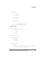
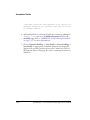
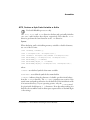
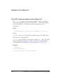
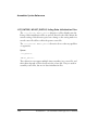
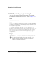
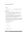
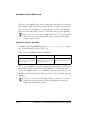
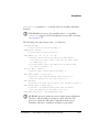
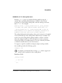
Code File Structure for Blackfin Processors
Figure 1-4 describes the Blackfin processor’s assembly code file structure
and shows how a program divides into sections that match the memory
segmentation of Blackfin processors.
Data Section
Assembler Directive
.SECTION constdata;
.VAR buffer1 [ 6 ] = "buffer1.dat";
Data Section
Assembler Directive
.SECTION data1;
.VAR buffer2[ 0x100];
Preprocessor Commands
for Conditional Assembly
#ifdef INCLUDE_BUFFER3
.VAR buffer3[ 0x100];
#endif
Code (program) Section
.SECTION program;
.global my_function;
Assembler Label
Assembly Instructions
my_function:
P0 = R0;
I0 = R1;
P1 = 19;
R0 = 0;
R1 = [P0++];
R2 = [I0++];
LSETUP (begin_loop, end_loop) LC0 = P1;
begin_loop:
R1 *= R2;
R2 = [I0++];
end_loop:
R0= R0 + R1 (NS) || R1 = [P0++] || NOP;
R1 *= R2;
R0 = R0 + R1;
Assembler Label
my_function.end:
Figure 1-4. Assembly Source File Structure for Blackfin Processors
VisualDSP++ 5.0 Assembler and Preprocessor Manual
1-17
Assembler Guide
You can use sections in a program to group elements to meet hardware
constraints. For example, the ADSP-BF535 processor has a separate program and data memory in Level 1 memory only. Level 2 memory and
external memory are not separated into instruction and data memory.
LDF for Blackfin Processors
Listing 1-3 on page 1-18 shows a sample user-defined linker description
file (.ldf). Looking at the file’s SECTIONS{} command, notice that the
INPUT_SECTION commands map to sections program, data1, and
constdata.
Listing 1-3. Example Linker Description File for Blackfin Processors
ARCHITECTURE(ADSP-BF535)
SEARCH_DIR($ADI_DSP\Blackfin\lib)
#define LIBS libc.dlb, libdsp.dlb
$LIBRARIES = LIBS, librt535.dlb;
$OBJECTS = $COMMAND_LINE_OBJECTS;
MEMORY
/* Define/label system memory
{
/* List of global Memory Segments */
MEM_PROGRAM
*/
{ TYPE(RAM) START(0xF0000000) END(0xF002FFFF)
WIDTH(8) }
MEM_HEAP
{ TYPE(RAM) START(0xF0030000) END(0xF0037FFF)
WIDTH(8) }
MEM_STACK
{ TYPE(RAM) START(0xF0038000) END(0xF003DFFF)
WIDTH(8) }
MEM_SYSSTACK { TYPE(RAM) START(0xF003E000) END(0xF003FDFF)
WIDTH(8) }
MEM_ARGV
{ TYPE(RAM) START(0xF003FE00) END(0xF003FFFF)
WIDTH(8) }
}
PROCESSOR p0
1-18
/* The processor in the system */
VisualDSP++ 5.0 Assembler and Preprocessor Manual
Assembler
{
OUTPUT($COMMAND_LINE_OUTPUT_FILE)
SECTIONS
{
/* List of sections for processor P0 */
program
{
/* Align all code sections on 2 byte boundary */
INPUT_SECTION_ALIGN(2)
INPUT_SECTIONS( $OBJECTS(program) $LIBRARIES(program))
INPUT_SECTION_ALIGN(1)
INPUT_SECTIONS( $OBJECTS(data1) $LIBRARIES(data1))
INPUT_SECTION_ALIGN(1)
INPUT_SECTIONS(
$OBJECTS(constdata)$LIBRARIES(constdata))
INPUT_SECTION_ALIGN(1)
INPUT_SECTIONS( $OBJECTS(ctor) $LIBRARIES(ctor))
INPUT_SECTION_ALIGN(2)
INPUT_SECTIONS( $OBJECTS(seg_rth))
} >MEM_PROGRAM
stack
{
ldf_stack_space = .;
ldf_stack_end = ldf_stack_space +
MEMORY_SIZEOF(MEM_STACK) - 4;
} >MEM_STACK
sysstack
{
ldf_sysstack_space = .;
ldf_sysstack_end = ldf_sysstack_space +
MEMORY_SIZEOF(MEM_SYSSTACK) - 4;
} >MEM_SYSSTACK
VisualDSP++ 5.0 Assembler and Preprocessor Manual
1-19
Assembler Guide
heap
{
/* Allocate a heap for the application */
ldf_heap_space = .;
ldf_heap_end = ldf_heap_space + MEMORY_SIZEOF(MEM_HEAP) - 1;
ldf_heap_length = ldf_heap_end - ldf_heap_space;
} >MEM_HEAP
argv
{
/* Allocate argv space for the application */
ldf_argv_space = .;
ldf_argv_end = ldf_argv_space + MEMORY_SIZEOF(MEM_ARGV) - 1;
ldf_argv_length = ldf_argv_end - ldf_argv_space;
} >MEM_ARGV
}
}
Program Interfacing Requirements
You can interface your assembly program with a C or C++ program.
The C/C++ compiler supports two methods for mixing C/C++ and
assembly language:
• Embedding assembly code in C or C++ programs
• Linking together C or C++ and assembly routines
To embed (inline) assembly code in your C or C++ program, use the
asm() construct. To link together programs that contain C/C++ and
assembly routines, use assembly interface macros. These macros facilitate
the assembly of mixed routines. For more information about these
methods, see the VisualDSP++ 5.0 C/C++ Compiler and Library Manual
for the appropriate target processor.
1-20
VisualDSP++ 5.0 Assembler and Preprocessor Manual
Assembler
When writing a C or C++ program that interfaces with assembly, observe
the same rules that the compiler follows as it produces code to run on the
processor. These rules for compiled code define the compiler’s run-time
environment. Complying with a run-time environment means following
rules for memory usage, register usage, and variable names.
The definition of the run-time environment for the C/C++ compiler is
provided in the VisualDSP++ 5.0 C/C++ Compiler and Library Manual for
the appropriate target processor, which also includes a series of examples
to demonstrate how to mix C/C++ and assembly code.
Using Assembler Support for C Structs
The assembler supports C typedef/struct declarations within assembly
source. These assembler data directives and built-ins provide high-level
programming features with C structs in the assembler.
Data Directives:
(see on page 1-90)
(see on page 1-83)
(see on page 1-130)
.IMPORT
.EXTERN STRUCT
.STRUCT
C Struct in Assembly Built-Ins:
OFFSETOF(struct/typedef,field
SIZEOF(struct/typedef)
(see on page 1-63)
(see on page 1-63)
Struct References:
struct->field
(support nests; see “Struct References” on page 1-64)
For more information on C struct support, refer to the “-flags-compiler”
command-line switch on page 1-154 and to “Reading a Listing File” on
page 1-34.
VisualDSP++ 5.0 Assembler and Preprocessor Manual
1-21
Assembler Guide
C structs in assembly features accept the full set of legal C symbol names,
including those that are otherwise reserved in the appropriate assembler.
For example,
• In the SHARC assembler, I1, I2, and I3 are reserved keywords,
but it is legal to reference them in the context of the C struct in
assembly features.
• In the TigerSHARC assembler, J1, J2, and J3 are reserved
keywords, but it is legal to reference them in the context of the C
struct in assembly features.
• In the Blackfin assembler, as an example, “X” and “Z” are reserved
keywords, but it is legal to reference them in the context of the C
struct in assembly features.
The examples below show how to access the parts of the struct defined in
the header file, but they are not complete programs on their own. Refer to
your DSP project files for complete code examples.
Blackfin Example:
.IMPORT "Coordinate.h";
/* typedef struct Coordinate {
int
X;
int
Y;
int
Z;
} Coordinate;*/
.SECTION data1;
.STRUCT Coordinate Coord1 = {
X = 1,
Y = 4,
Z = 7
};
1-22
VisualDSP++ 5.0 Assembler and Preprocessor Manual
Assembler
.SECTION program;
P0.l = Coord1->X;
P0.h = Coord1->X;
P1.l = Coord1->Y;
P1.h = Coord1->Y;
P2.l = Coord1->Z;
P2.h = Coord1->Z;
P3.l = Coord1+OFFSETOF(Coordinate,Z);
P3.h = Coord1+OFFSETOF(Coordinate,Z);
SHARC Example:
.IMPORT "Samples.h";
/*
typedef struct Samples {
int I1;
int I2;
int I3;
} Samples; */
.SECTION/DM seg_dmda;
.STRUCT Samples Sample1 ={
I1 = 0x1000,
I2 = 0x2000,
I3 = 0x3000
};
.SECTION/PM seg_pmco;
doubleMe:
/* The code may look confusing, but I2 can be used both
as a register and a struct member name */
VisualDSP++ 5.0 Assembler and Preprocessor Manual
1-23
Assembler Guide
B2 = Sample1;
M2 = OFFSETOF(Sample1,I2);
R0 = DM(M2,I2);
R0 = R0+R0;
DM(M2,I2) = R0;
better code readability, avoid using
member names
L For
that have the same spelling as assembler keywords. This may not
.STRUCT
always be possible if your application needs to use an existing set of
C header files.
Preprocessing a Program
The assembler includes a preprocessor that allows the use of C-style
preprocessor commands in your assembly source files. The preprocessor
automatically runs before the assembler unless you use the assembler’s -sp
(skip preprocessor) switch. Table 2-5 on page 2-23 lists preprocessor
commands and provides a brief description of each command.
You can see the command line that the assembler uses to invoke the preprocessor by adding the -v switch (on page 1-167) to the assembler
command line or by selecting the Generate verbose output option on the
Assemble page of the Project Options dialog box. See “Specifying Assembler Options in VisualDSP++” on page 1-170.
Use preprocessor commands to modify assembly code. For example,
you can use the #include command to fill memory, load configuration
registers, or set up processor parameters. You can use the #define command to define constants and aliases for frequently used instruction
sequences. The preprocessor replaces each occurrence of the macro
reference with the corresponding value or series of instructions.
For example, the MAXIMUM macro from #define
with the number 100 during preprocessing.
1-24
MAXIMUM 100
is replaced
VisualDSP++ 5.0 Assembler and Preprocessor Manual
Assembler
For more information on the preprocessor command set, see “Preprocessor Command Reference” on page 2-22. For more information on the
preprocessor usage, see “-flags-pp -opt1 [,-opt2...]” on page 1-156.
is one important difference between the assembler preproL There
cessor and compiler preprocessor. The assembler preprocessor
treats the “.” character as part of an identifier. Thus, .EXTERN is a
single identifier and will not match a preprocessor macro EXTERN.
This behavior can affect how macro expansion is done for some
instructions.
For example,
#define EXTERN ox123
.EXTERN Coordinate;
/* EXTERN not affected by macro */
#define MY_REG P0
MY_REG.1 = 14;
/* MY_REG.1 is not expanded; */
/* "." is part of token */
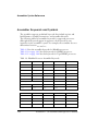
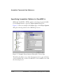
Using Assembler Feature Macros
The assembler includes the command to invoke preprocessor macros to
define the context, such as the source language, the architecture, and the
specific processor. These feature macros allow programmers to use preprocessor conditional commands to configure the source for assembly based
on the context.
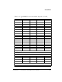
Table 1-5 lists the set of feature macros for Blackfin processors. Table 1-6
on page 1-28 lists the set of feature macros for SHARC processors.
Table 1-7 on page 1-30 lists the set of feature macros for TigerSHARC
processors.
VisualDSP++ 5.0 Assembler and Preprocessor Manual
1-25
Assembler Guide
Table 1-5. Feature Macros for Blackfin Processors
-D_LANGUAGE_ASM=1
Always present
-D__ADSPBLACKFIN__ =1
Always present
-D__ADSPLPBLACKFIN__ =1
Always present for non-ADSP-BF535 processors
-D__ADSPBF51x__=1
Present when running:
easmblkfn -proc ADSP-BF512
easmblkfn -proc ADSP-BF514
easmblkfn -proc ADSP-BF516
-D__ADSPBF52x__=1
Present when running:
easmblkfn
easmblkfn
easmblkfn
easmblkfn
easmblkfn
easmblkfn
-D__ADSPBF54x__=1
-proc
-proc
-proc
-proc
-proc
-proc
ADSP-BF522
ADSP-BF523
ADSP-BF524
ADSP-BF525
ADSP-BF526
ADSP-BF527
Present when running:
easmblkfn
easmblkfn
easmblkfn
easmblkfn
easmblkfn
-proc
-proc
-proc
-proc
-proc
ADSP-BF542
ADSP-BF544
ADSP-BF547
ADSP-BF548
ADSP-BF549
-D__ADSPBF512__=1
Present when running easmblkfn -proc ADSP-BF512
with the ADSP-BF512 processor
-D__ADSPBF514__=1
Present when running easmblkfn -proc ADSP-BF514
with the ADSP-BF514 processor
-D__ADSPBF516__=1
Present when running easmblkfn -proc ADSP-BF516
with the ADSP-BF516 processor
-D__ADSPBF522__=1
Present when running easmblkfn -proc ADSP-BF522
with the ADSP-BF522 processor
-D__ADSPBF523__=1
Present when running easmblkfn -proc ADSP-BF523
with the ADSP-BF523 processor
-D__ADSPBF524__=1
Present when running easmblkfn -proc ADSP-BF524
with the ADSP-BF524 processor
-D__ADSPBF525__=1
Present when running easmblkfn -proc ADSP-BF525
with the ADSP-BF525 processor
1-26
VisualDSP++ 5.0 Assembler and Preprocessor Manual
Assembler
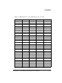
Table 1-5. Feature Macros for Blackfin Processors (Cont’d)
-D__ADSPBF526__=1
Present when running easmblkfn -proc ADSP-BF526
with the ADSP-BF526 processor
-D__ADSPBF527__=1
Present when running easmblkfn -proc ADSP-BF527
with the ADSP-BF527 processor
-D__ADSPBF531__=1
-D__ADSP21531__=1
Present when running easmblkfn -proc ADSP-BF531
with the ADSP-BF531 processor
-D__ADSPBF532__=1
-D__ADSP21532__=1
Present when running easmblkfn -proc ADSP-BF532
with the ADSP-BF532 processor
-D__ADSPBF533__=1
-D__ADSP21533__=1
Present when running easmblkfn -proc ADSP-BF533
with the ADSP-BF533 processor
-D__ADSPBF534__=1
Present when running easmblkfn -proc ADSP-BF534
with the ADSP-BF534 processor
-D__ADSPBF535__=1
-D__ADSP21535__=1
Present when running easmblkfn -proc ADSP-BF535
with the ADSP-BF535 processor
-D__ADSPBF536__=1
Present when running easmblkfn -proc ADSP-BF536
with the ADSP-BF536 processor
-D__ADSPBF537__=1
Present when running easmblkfn -proc ADSP-BF537
with the ADSP-BF537 processor
-D__ADSPBF538__=1
Present when running easmblkfn -proc ADSP-BF538
with the ADSP-BF538 processor
-D__ADSPBF539__=1
Present when running easmblkfn -proc ADSP-BF539
with the ADSP-BF539 processor
-D__ADSPBF542__=1
Present when running easmblkfn -proc ADSP-BF542
with the ADSP-BF542 processor
-D__ADSPBF544__=1
Present when running easmblkfn -proc ADSP-BF544
with the ADSP-BF544 processor
-D__ADSPBF547__=1
Present when running easmblkfn -proc ADSP-BF547
with the ADSP-BF547processor
-D__ADSPBF548__=1
Present when running easmblkfn -proc ADSP-BF548
with the ADSP-BF548 processor
VisualDSP++ 5.0 Assembler and Preprocessor Manual
1-27
Assembler Guide
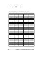
Table 1-5. Feature Macros for Blackfin Processors (Cont’d)
-D__ADSPBF549__=1
Present when running easmblkfn -proc ADSP-BF549
with the ADSP-BF549 processor
-D__ADSPBF561__=1
Present when running easmblkfn -proc ADSP-BF561
with the ADSP-BF561 processor
Table 1-6. Feature Macros for SHARC Processors
-D_LANGUAGE_ASM=1
Always present
-D__ADSP21000__=1
Always present
-D__ADSP21020__=1
-D__2102x__=1
Present when running easm21K -proc ADSP-21020
with the ADSP-21020 processors
-D__ADSP21060__=1
-D__2106x__=1
Present when running easm21K -proc ADSP-21060
with the ADSP-21060 processors
-D__ADSP21061__=1
-D__2106x__=1
Present when running easm21K -proc ADSP-21061
with the ADSP-21061 processors
-D__ADSP21062__=1
-D__2106x__=1
Present when running easm21K -proc ADSP-21062
with the ADSP-21062 processors
-D__ADSP21065L__=1
-D__2106x__=1
Present when running easm21K -proc ADSP-21065L
with the ADSP-21065L processors
-D__ADSP21160__=1
-D__2116x__=1
Present when running easm21K -proc ADSP-21160
with the ADSP-21160 processors
-D__ADSP21161__=1
-D__2116x__=1
Present when running easm21K -proc ADSP-21161
with the ADSP-21161 processors
-D__ADSP21261__=1
-D__2126x__=1
Present when running easm21K -proc ADSP-21261
with the ADSP-21261 processors
-D__ADSP21262__=1
-D__2126x__=1
Present when running easm21K -proc ADSP-21262
with the ADSP-21262 processors
-D__ADSP21266__=1
-D__2126x__=1
Present when running easm21K -proc ADSP-21266
with the ADSP-21266 processors
-D__ADSP21267__=1
-D__2126x__=1
Present when running easm21K -proc ADSP-21267
with the ADSP-21267 processors
1-28
VisualDSP++ 5.0 Assembler and Preprocessor Manual
Assembler
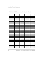
Table 1-6. Feature Macros for SHARC Processors (Cont’d)
-D__ADSP21362__=1
-D__2136x__=1
Present when running easm21K -proc ADSP-21362
with the ADSP-21362 processors
-D__ADSP21363__=1
-D__2136x__=1
Present when running easm21K -proc ADSP-21363
with the ADSP-21363 processors
-D__ADSP21364__=1
-D__2136x__=1
Present when running easm21K -proc ADSP-21364
with the ADSP-21364 processors
-D__ADSP21365__=1
-D__2136x__=1
Present when running easm21K -proc ADSP-21365
with the ADSP-21365 processors
-D__ADSP21366__=1
-D__2136x__=1
Present when running easm21K -proc ADSP-21366
with the ADSP-21366 processors
-D__ADSP21367__=1
-D__2136x__=1
Present when running easm21K -proc ADSP-21367
with the ADSP-21367 processors
-D__ADSP21368__=1
-D__2136x__=1
Present when running easm21K -proc ADSP-21368
with the ADSP-21368 processors
-D__ADSP21369__=1
-D__2136x__=1
Present when running easm21K -proc ADSP-21369
with the ADSP-21369 processors
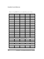
-D__ADSP2137x__=1
-D__2137x__=1
Present when running easm21K -proc ADSP-2137x
with the ADSP-2137x processors
-D__ADSP21371__=1
-D__2137x__=1
Present when running easm21K -proc ADSP-21371
with the ADSP-21371 processors
-D__ADSP21375__=1
-D__2137x__=1
Present when running easm21K -proc ADSP-21375
with the ADSP-21375 processors
-D__ADSP21462__=1
-D__2146x__=1
-D__214xx__=1
Present when running easm21K -proc ADSP-21462
with the ADSP-21462 processors
-D__ADSP21465__=1
-D__2146x__=1
-D__214xx__=1
Present when running easm21K -proc ADSP-21465
with the ADSP-21465 processors
-D__ADSP21467__=1
-D__2146x__=1
-D__214xx__=1
Present when running easm21K -proc ADSP-21467
with the ADSP-21467 processors
VisualDSP++ 5.0 Assembler and Preprocessor Manual
1-29
Assembler Guide
Table 1-6. Feature Macros for SHARC Processors (Cont’d)
-D__ADSP21469__=1
-D__2146x__=1
-D__214xx__=1
Present when running easm21K -proc ADSP-21469
with the ADSP-21469 processors
-D__NORMAL_WORD_CODE__=1
Present when running
easm21K
easm21K
easm21K
easm21K
-proc
-proc
-proc
-proc
ADSP-21462
ADSP-21465
ADSP-21467
ADSP-21469
and building in normal-word
mode
-D__SHORT_WORD_CODE__=1
Present when running
easm21K
easm21K
easm21K
easm21K
-proc
-proc
-proc
-proc
ADSP-21462
ADSP-21465
ADSP-21467
ADSP-21469
and building in short-word
mode
Table 1-7. Feature Macros for TigerSHARC Processors
-D_LANGUAGE_ASM =1
Always present
-D__ADSPTS__ =1
Always present
-D__ADSPTS101__ =1
Present when running easmts -proc ADSP-TS101
with the ADSP-TS101 processor
-D__ADSPTS201__ =1
Present when running easmts -proc ADSP-TS201
with the ADSP-TS201 processor
-D__ADSPTS202__ =1
Present when running easmts -proc ADSP-TS202
with the ADSP-TS202 processor
-D__ADSPTS203__ =1
Present when running easmts -proc ADSP-TS203
with the ADSP-TS203 processor
-D__ADSPTS20x__ =1
Present when running
easmts -proc ADSP-TS201 with the ADSP-TS201 processor
easmts -proc ADSP-TS202 with the ADSP-TS202 processor
asmts -proc ADSP-TS203 with the ADSP-TS203 processor
1-30
VisualDSP++ 5.0 Assembler and Preprocessor Manual
Assembler
For .IMPORT headers, the assembler calls the compiler driver with the
appropriate processor option, and the compiler sets the machine constants
accordingly (and defines -D_LANGUAGE_C=1). This macro is present when
used for C compiler calls to specify headers. It replaces -D_LANGUAGE_ASM.
For example,
easm21k -proc adsp-21262
assembly
--> cc21K
easmts -proc -ADSP-TS101
assembly
--> ccts
easmblkfn -proc ADSP-BF535
assembly
-proc adsp-21262
-proc ADSP-TS101
--> ccblkfn
-proc ADSP-BF535
the
switch to verify what macro is default-defined.
L Use
Refer to Chapter 1 in the VisualDSP++ 5.0 C/C++ Compiler and
-verbose
Library Manual of the appropriate target processor for more
information.
-D__VISUALDSPVERSION__ Predefined Macro
The macro applies to all Analog Devices processors.
L
The
predefined macro provides product version
-D__VISUALDSPVERSION__
information to VisualDSP++. The macro allows a preprocessing check to
be placed within code and is used to differentiate between VisualDSP++
releases and updates.
Syntax:
-D__VISUALDSPVERSION__=0xMMmmUUxx
Table 1-8 explains the macro parameters.
The 0xMMmmUUxx information is obtained from the <install_path>\System\VisualDSP.ini file. Initially, xx is set to “00”.
If an unexpected problem occurs while trying to locate VisualDSP.ini or
while extracting information from the VisualDSP.ini file, the
__VISUALDSPVERSION__ macro is not encoded to the VisualDSP++ product
VisualDSP++ 5.0 Assembler and Preprocessor Manual
1-31
Assembler Guide
Table 1-8. -D__VISUALDSPVERSION__ Decoding of Hex Value
Parameter
Description
MM
VersionMajor. The major release number; for example, 4 in release 4.5.
mm
VersionMinor. The minor release number; for example, 5 in release 4.5.
UU
VersionPatch. The number of the release update; for example, 6 in release 4.5,
update 6.
xx
Reserved for future use (always 00 initially)
version. In the Error Check example below, the -D__VISUALDSPVERSION__
string is displayed as part of an error message when the version
information is unable to be encoded.
0xffffffff
Code Example (Legacy ):
#if !defined(__VISUALDSPVERSION__)
#warning Building with VisualDSP++ 4.5 Update 5 or prior. No
__VISUALDSPVERSION__ available.
#endif
Code Example (VisualDSP++ 4.5 Update 6 or Later):
#if __VISUALDSPVERSION__ >= 0x04050600
#warning Building with VisualDSP++ 4.5 Update 6 or later
#endif
Code Example (Error Check):
#if __VISUALDSPVERSION__ == 0xffffffff
#error Unexpected build problems, unknown VisualDSP++ Version
#endif
Code Examples (Assembly):
#if __VISUALDSPVERSION__ == 0x05000000
/* Building with VisualDSP++ 5.0 */
.VAR VersionBuildString[] = ‘Building with VisualDSP++ 5.0’;
1-32
VisualDSP++ 5.0 Assembler and Preprocessor Manual
Assembler
#elif __VISUALDSPVERSION__ == 0x04050600
/* Building with VisualDSP++ 4.5, Update 6 */
.VAR VersionBuildString[] = 'Building with VisualDSP++ 4.5 Update
6';
#else
/* Building with unknown VisualDSP++ version */
.VAR VersionBuildString[] = 'Building with unknown VisualDSP++
version?';
#endif
Generating Make Dependencies
The assembler can generate make dependencies for a file, allowing
VisualDSP++ and other makefile-based build environments to determine
when to rebuild an object file due to changes in the input files. The assembly source file and any files identified in the #include commands, .IMPORT
directives, or buffer initializations (in .VAR and .STRUCT directives) constitute the make dependencies for an object file.
When you request make dependencies for the assembly, the assembler
produces the dependencies from buffer initializations. The assembler also
invokes the preprocessor to determine the make dependency from
#include commands, and the compiler to determine the make
dependencies from the .IMPORT headers.
For example,
easmblkfn -proc ADSP-BF533 -MM main.asm
"main.doj": "/VisualDSP/Blackfin/include/defBF532.h"
"main.doj": "/VisualDSP/Blackfin/include/defBF533.h"
"main.doj": "/VisualDSP/Blackfin/include/def_LPBlackfin.h"
"main.doj": "main.asm"
"main.doj": "input_data.dat"
VisualDSP++ 5.0 Assembler and Preprocessor Manual
1-33
Assembler Guide
The original source file main.asm is as follows:
...
#include "defBF533.h"
...
.GLOBAL input_frame;
.BYTE input_frame[N] = "input_data.dat"; /* load in 256 values
from a test file */
...
In this case, defBF533.h includes defBF532.h, which also includes
def_LPBlackfin.h.
Reading a Listing File
A listing file (.lst) is an optional output text file that lists the results of
the assembly process. Listing files provide the following information:
• Address – The first column contains the offset from the .SECTION’s
base address.
• Opcode – The second column contains the hexadecimal opcode
that the assembler generates for the line of assembly source.
• Line – The third column contains the line number in the assembly
source file.
• Assembly Source – The fourth column contains the assembly
source line from the file.
The assembler listing file provides information about the imported C data
structures. It tells which imports were used within the program, followed
by a more detailed section. It shows the name, total size, and layout with
offset for the members. The information appears at the end of the listing.
You must specify the -l filename option (as described on page 1-159)
to produce a listing file.
1-34
VisualDSP++ 5.0 Assembler and Preprocessor Manual
Assembler
Enabling Statistical Profiling for Assembly
Functions
Use the following steps to enable statistical profiling in assembler sources.
1. When using the VisualDSP++ IDDE, use the Assemble page of the
Project Options dialog box (Figure 1-6 on page 1-171) to select
and/or set assembler functional options.
2. Select the Generate debug information option.
3. Mark ending function boundaries with .end labels in the assembler
source. For example:
.SECTION program;
.GLOBAL funk1;
funk1:
...
RTS;
funk1.end:
.GLOBAL funk2;
funk2:
...
RTS;
funk2.end:
If you have global functions without ending labels, the assembler
provides warnings when debug information is generated.
.GLOBAL funk3;
funk3:
...
RTS;
[Warning ea1121] "test.asm":14 funk3: -g assembly with
global function without ending label. Use 'funk3.end' or
VisualDSP++ 5.0 Assembler and Preprocessor Manual
1-35
Assembler Guide
'funk3.END' to mark the ending boundary of the function for
debugging information for automated statistical profiling
of assembly functions.
4. Add ending labels or selectively disable the warning by adding the
-Wsuppress 1121 option to the Additional options field on the
Assembly page (refer to “WARNING ea1121: Missing End Labels”
on page 1-157 for more information).
5. Choose Statistical Profiling -> New Profile or Linear Profiling ->
New Profile, as appropriate. Assembler functions automatically
appear in the profiling window along with C functions. Click on
the function name to bring up the source containing the function
definition.
1-36
VisualDSP++ 5.0 Assembler and Preprocessor Manual
Assembler
Assembler Syntax Reference
When developing a source program in assembly language, include
preprocessor commands and assembler directives to control the program’s
processing and assembly. You must follow the assembler rules and syntax
conventions to define symbols (identifiers) and expressions, and to use
different numeric and comment formats.
Software developers who write assembly programs should be familiar with:
• “Assembler Keywords and Symbols” on page 1-38
• “Assembler Expressions” on page 1-50
• “Assembler Operators” on page 1-51
• “Numeric Formats” on page 1-56
• “Comment Conventions” on page 1-60
• “Conditional Assembly Directives” on page 1-60
• “C Struct Support in Assembly Built-In Functions” on page 1-63
• “Struct References” on page 1-64
• “Assembler Directives” on page 1-67
VisualDSP++ 5.0 Assembler and Preprocessor Manual
1-37
Assembler Syntax Reference
Assembler Keywords and Symbols
The assembler supports predefined keywords that include register and
bitfield names, assembly instructions, and assembler directives.
The following tables list assembler keywords for supported processors.
Although the keywords appear in uppercase, the keywords are case
insensitive in the assembler’s syntax. For example, the assembler does not
differentiate between MAX and max.
Table 1-9 lists the assembler keywords for Blackfin processors.
Table 1-10 on page 1-41 lists the keywords for SHARC processors.
Table 1-11 on page 1-44 lists the keywords for TigerSHARC processors.
Table 1-9. Blackfin Processor Assembler Keywords
.ALIGN
.ASCII
.ASM_ASSERT
.ASSERT
.BSS
.BYTE
.BYTE2
.BYTE4
.DATA
.ELIF
.ELSE
.ENDIF
.ELSE
.ENDIF
.EXTERN
.FILE
.FILE_ATTR
.GLOBAL
.GLOBL
.IF
.INC/BINARY
.INCBIN
.IMPORT
.LEFTMARGIN
.LIST
.LIST_DATA
.LIST_DATFILE
.LIST_DEFTAB
.LIST_LOCTAB
.LIST_WRAPDATA
.LONG
.NEWPAGE
.NOLIST
.NOLIST_DATA
.NOLIST_DATFILE
.NOLIST_WRAPDATA
.PAGELENGTH
.PAGEWIDTH
.PREVIOUS
.SECTION
.SET SYMBOL
.SYMBOL
.SHORT
.STRUCT
.TEXT
.TYPE
.VAR
.WEAK
A0
A1
ABORT
ABS
AC
ALIGN8
ALIGN16
ALIGN24
AMNOP
AN
AND
ASHIFT
ASL
ASR
ASSIGN
ASTAT
AV0
AV1
AZ
B
B0
B1
B2
1-38
B3
VisualDSP++ 5.0 Assembler and Preprocessor Manual
Assembler
Table 1-9. Blackfin Processor Assembler Keywords (Cont’d)
BANG
BAR
BITCLR
BITMUX
BITPOS
BITSET
BITTGL
BITTST
BIT_XOR_AC
BP
BREV
BRF
BRT
BY
BYTEOP1P
BYTEOP16M
BYTEOP1NS
BYTEOP16P
BYTEOP3P
BYTEPACK
BYTEUNPACK
BXOR
BXORSHIFT
CALL
CARET
CC
CLI
CLIP
CO
CODE
COLON
COMMA
CSYNC
DATA
DEPOSIT
DISALGNEXCPT
DIVSDEPOSIT
DISALGNEXCPT
DIVSDEPOSIT
DM
DOZE
DIVQ
DIVS
DOT
EMUCAUSE
EMUEXCPT
EXCAUSE
EXCPT
EXPADJ
EXTRACT
FEXT
FEXTSX
FLUSH
FLUSHINV
FP
GE
GF
GT
H
HI
HLT
HWERRCAUSE
I0
I1
I2
I3
IDLE
IDLE_REQ
IFLUSH
IH
INTRP
IS
ISS2
IU
JUMP
JUMP.L
JUMP.S
L
LB0
LB1
LC0
LC1
LE
LENGTH
LINK
LJUMP
LMAX
LMIN
LO
LOOP
LOOP_BEGIN
LOOP_END
LPAREN
LSETUP
LSHIFT
LT
LT0
LT1
LZ
M
M0
M1
M2
M3
MAX
MIN
MINUS
MNOP
MUNOP
NEG
NO_INIT
NOP
NOT
NS
BYTEOP2P
FU
VisualDSP++ 5.0 Assembler and Preprocessor Manual
1-39
Assembler Syntax Reference
Table 1-9. Blackfin Processor Assembler Keywords (Cont’d)
ONES
OR
OUTC
P0
P1
P2
P3
P4
P5
PACK
PC
PERCENT
PLUS
PM
PREFETCH
PRNT
R
R0
R1
R2
R3
R32
R4
R5
R6
R7
RAISE
RBRACE
RBRACK
RETI
RETN
RETS
RETX
RND
RND12
RND20
RNDH
RNDL
ROL
ROR
ROT
ROT_L_AC
ROT_R_AC
RPAREN
RSDL
RTE
RTI
RTN
RTS
RTX
RUNTIME_INIT
R1_COLON0
RETAIN_NAME
S
S2RND
SAA
SAA1H
SAA1L
SAA2H
SAA2L
SAA3H
SAA3L
SAT
SCO
SEARCH
SHT_TYPE
SIGN
SIGNBITS
SLASH
SLEEP
SKPF
SKPT
SP
SS
SSF
SSF_RND_HI
SSF_TRUNC
SSF_TRUNC_HI
SSF_RND
SSF_TRUNC
SSYN
STI
STRUCT
STT_TYPE
SU
SYSCFG
T
TESTSET
TFU
TH
TL
UNLINK
UNLNK
UNRAISE
UU
V
VIT_MAX
W
W32
WEAK
X
XB
XH
TST
XOR
Z
ZERO_INIT
1-40
VisualDSP++ 5.0 Assembler and Preprocessor Manual
Assembler
Table 1-9. Blackfin Processor Assembler Keywords (Cont’d)
_ADI_
_DATE_
_FILE_
_LastSuffix_
_LINE_
_TIME_
Table 1-10. SHARC Processor Assembler Keywords
__ADI__
__DATE__
__FILE__
__LastSuffix__ __LINE__
__NORMAL_WORD_CODE__
__SHORT_WORD_CODE__
__TIME__
.ALIGN
.COMPRESS
.ELIF
.ELSE
.ENDIF
.EXTERN
.FILE
.FILE_ATTR
.FORCECOMPRESS .GLOBAL
.IF
.IMPORT
.LEFTMARGIN
.LIST
.LIST_DATFILE
.LIST_DEFTAB
.LIST_LOCTAB
.LIST_WRAPDATA .NEWPAGE
.NOCOMPRESS
.NOLIST_DATA
.NOLIST_DATFILE .NOLIST_WRAPDATA
.PAGELENGTH
.PAGEWIDTH
.PRECISION
.ROUND_MINUS
.ROUND_NEAREST
.ROUND_PLUS
.ROUND_ZERO
.PREVIOUS
.SECTION
.STRUCT
.VAR
.WEAK
ABS
ACS
ACT
ADDRESS
AND
ASHIFT
ASTAT
AV
B0
B1
B2
B3
B4
B5
B6
B7
B8
B9
B10
B11
B12
B13
B14
B15
BB
BCLR
BF
BIT
BITREV
BM
BSET
BTGL
BTSTS
CA
CACHE
CALL
CH
CI
CJUMP
CL
CLIP
COMP
COPYSIGN
COS
CURLCNTR
.LIST_DATA
BY
VisualDSP++ 5.0 Assembler and Preprocessor Manual
1-41
Assembler Syntax Reference
Table 1-10. SHARC Processor Assembler Keywords (Cont’d)
DADDR
DB
DEC
DEF
DIM
DM
DMA1E
DMA1S
DMA2E
DMA2S
DMADR
DMABANK1
DMABANK2
DMABANK3
DMAWAIT
DO
DOVL
EB
ECE
EF
ELSE
EMUCLK
EMUCLK2
EMUIDLE
EMUN
ENDEF
EOS
EQ
EX
EXP
EXP2
F0
F1
F2
F3
F4
F5
F6
F7
F8
F9
F10
F11
F12
F13
F14
F15
FADDR
FDEP
FEXT
FILE
FIX
FLAGO_IN
FLAG1_IN
FLAG2_IN
FLAG3_IN
FLOAT
FLUSH
FMERG
FOREVER
FPACK
FRACTIONAL
FTA
FTB
FTC
FUNPACK
GCC_COMPILED
GE
GT
I0
I1
I2
I3
I4
I5
I6
I7
I8
I9
I10
I11
I12
I13
I14
I15
IDLEI15
IDLE16
IF
IMASK
IMASKP
INC
IRPTL
L0
L1
L2
L3
L4
L5
L6
L7
L8
L9
L10
L11
L12
L13
L14
L15
LA
LADDR
LCE
LCNTR
LE
LADDR
LCE
LCNTR
LE
L15
LA
LADDR
LCE
LCNTR
JUMP
1-42
VisualDSP++ 5.0 Assembler and Preprocessor Manual
Assembler
Table 1-10. SHARC Processor Assembler Keywords (Cont’d)
LE
LEFTO
LEFTZ
LENGTH
LINE
LN
LOAD
LOG2
LOOP
LR
LSHIFT
LT
M0
M1
M2
M3
M4
M5
M6
M7
M8
M9
M10
M11
M12
M13
M14
M15
MANT
MAX
MBM
MIN
MOD
MODE1
MODE2
MODIFY
MROB
MROF
MR1B
MR1F
MR2B
MR2F
MRB
MRF
MS
MV
MROB
NE
NOFO
NOFZ
NOP
NOPSPECIAL
NOT
NU
NW
OFFSETOF
OR
P20
P32
P40
PACK
PAGE
PC
PCSTK
PCSTKP
PM
PMADR
PMBANK1
PMDAE
PMDAS
POP
POVLO
POVL1
PSA1E
PSA1S
PSA2E
PSA3E
PSA3S
PSA4E
PSA4S
PUSH
PX
PX1
PX2
R0
R1
R2
R3
R4
RF5
R6
R7
R8
R9
R10
R11
R12
R13
R14
R15
READ
RECIPS
RFRAME
RND
ROT
RS
RSQRTS
RTI
RTS
SCALB
SCL
SE
SET
SF
SIN
SIZE
SIZEOF
SQR
SR
LOGB
MROF
RETAIN_NAME
VisualDSP++ 5.0 Assembler and Preprocessor Manual
1-43
Assembler Syntax Reference
Table 1-10. SHARC Processor Assembler Keywords (Cont’d)
SSF
SSFR
SSI
SSIR
ST
STEP
STKY
STRUCT
STS
SUF
SUFR
SV
SW
SZ
TAG
TCOUNT
TF
TGL
TPERIOD
TRUE
TRUNC
TST
TYPE
TRAP
UF
UI
UNPACK
UNTIL
UR
USF
USFR
USI
USIR
USTAT1
USTAT2
UUF
UUFR
UUIR
UUIR
VAL
WITH
XOR
Table 1-11. TigerSHARC Processor Assembler Keywords
__ADI__
__DATE__
__FILE__
__LastSuffix__
__LINE__
.ALIGN
.ALIGN_CODE
.ELIF
.ELSE
.ENDIF
.EXTERN
.FILE
.FILE_ATTR
.GLOBAL
.IF
.IMPORT
.LEFTMARGIN
.LIST
.LIST_DATA
.LIST_DATFILE
.LIST_DEFTAB
.LIST_LOCTAB
.LIST_WRAPDATA .MESSAGE
__TIME__
.NOLIST_DATFILE .NOLIST_WRAPDATA .NEWPAGE
.PAGELENGTH
.NOLIST_DATA
.PAGEWIDTH
.PREVIOUS
.SECTION
.SEPARATE_MEM_SEGMENTS
.SECTION
.VAR
.WEAK
ABS
ACS
ADDRESS
AND
ASHIFT
BCLR
BFOINC
BFOTMP
BITEST
BITFIFO
BKFPT
BR
BSET
BTBDIS
BTBELOCK
BTBEN
BTBLOCK
BTBINV
BTGL
BY
C
CALL
CB
CJMP
CJMP_CALL
CI
CLIP
COMP
COMPACT
COPYSIGN
1-44
.SET
VisualDSP++ 5.0 Assembler and Preprocessor Manual
Assembler
Table 1-11. TigerSHARC Processor Assembler Keywords (Cont’d)
DAB
DEC
DESPREAD
D0
ELSE
EMUTRAP
EXP
EXPAND
EXTD
FCOMP
FDEP
FEXT
FIX
FLOAT
FTEST0
FTEST1
FOR
GETBITS
IDLE
INC
JC
JUMP
KC
LD0
LD1
LENGTH
LINES
LP
LSHIFT
LSHIFTR
LIBSIM_CALL
MANT
MASK
MAX
MERGE
NEWPAGE
NOT
NOP
NP
OFFSETOF
ONES
OR
PASS
PERMUTE
PRECISION
PUTBITS
RDS
RECIPS
RESET
RETI
ROT
ROTL
ROTR
ROUND
RSQRTS
RTI
SCALB
SDAB
SE
SECTION
SFO
SF1
SNGL
SIZE
SIZEOF
STRUCT
SUM
TMAX
TRAP
TYPEVAR
UNTIL
VMIN
VMAX
XCORRS
XOR
XSDAB
YDAB
YSDAB
LOGB
MIN
JK Register Group
J0
through J31
K0
through K31
JB0
JB1
JB2
JB3
KB0
KB1
KB2
KB3
JL0
JL1
JL2
JL3
KL0
KL1
KL2
KL3
RF Register Group
FR0
through FR31
VisualDSP++ 5.0 Assembler and Preprocessor Manual
1-45
Assembler Syntax Reference
Table 1-11. TigerSHARC Processor Assembler Keywords (Cont’d)
MR3:0
MR3:2
MR1:0
MR0
MR1
MR2
PR0
PR1
PR1:0
YSTAT
XYSTAT
R0
MR3
MR4
through R31
XSTAT
XR0
through XR31
YR0
through YR31
Accelerator Register Group
TR0
through TR31
THR0
THR1
THR2
THR3
BMAX
BMAXC
BUSLK
FLGPIN
FLGPINCL
FLGPINST
SDRCON
SYSCON
SYSCONCL
SYSCONST
SYSCTL
SYSTAT
SYSTATCL
CACMD8
CACMD10
EP Register Group
Misc. Register Group
AUTODMA0
AUTODMA1
BTBCMD
BTBDATA
BTB0TG0
through BTB0TG31
BTB1TG0
through BTB1TG31
BTB2TG0
through BTB2TG31
BTB3TG0
through BTB3TG31
BTB0TR0
through BTB0TR31
BTB1TR0
through BTB1TR31
BTB2TR0
through BTB2TR31
BTB3TR0
through BTB3TR31
BTBLRU0
through BTBLRU31
CACMD0
1-46
CACMD2
CACMD4
VisualDSP++ 5.0 Assembler and Preprocessor Manual
Assembler
Table 1-11. TigerSHARC Processor Assembler Keywords (Cont’d)
CACMDALL
CADATA0
CADATA2
CADATA4
CADATA8
CADATA10
CASTAT2
CASTAT4
CASTAT8
CASTAT10
CCAIR2
CCAIR4
CCAIR8
CCAIR10
CCNT0
CCNT1
CJMP
CMCTL
DBGE
DC4
DCD0
DCD1
DCD2
DCD3
DCNTCL
DCNTST
DCS0
DCS1
DCS2
DCS3
DSTAT
DSTATC
EMUCTL
EMUDAT
EMUIR
EMUSTAT
IDCODE
ILATCLH
ILATCLL
ILATH
ILATL
ILATSTH
ILATSTL
IMASKH
IMASKL
INSTAT
INTEN
INTCTL
IVBUSLK
IVDBG
IVHW
CADATAALL
CASTAT0
CASTATALL
CCAIR0
CCAIRALL
IVDMA0
through DC13
DCNT
through IVDMA13
IVIRQ0
IVIRQ1
IVIRQ2
IVIRQ3
IVLINK0
IVLINK1
IVLINK2
IVLINK3
IVSW
IVTIMER0HP
IVTIMER0LP
IVTIMER1HP
IVTIMER1LP
LBUFRX0
LBUFRX1
LBUFRX2
LBUFRX3
LBUFTX0
LBUFTX1
LBUFTX2
LBUFTX3
LC0
LC1
KB2
KB3
LCTL0
LCTL1
LCTL2
LCTL3
LRCTL0
LRCTL1
LRCTL2
LRCTL3
LRSTAT0
LRSTAT1
LRSTAT2
LRSTAT3
VisualDSP++ 5.0 Assembler and Preprocessor Manual
1-47
Assembler Syntax Reference
Table 1-11. TigerSHARC Processor Assembler Keywords (Cont’d)
LRSTATC0
LRSTATC1
LRSTATC2
LRSTATC3
LSTAT0
LSTAT1
LSTAT2
LSTAT3
LSTATC0
LSTATC1
LSTATC2
LSTATC3
LTCTL0
LTCTL1
LTCTL2
LTCTL3
LTSTAT0
LTSTAT1
LTSTAT2
LTSTAT3
LTSTATC0
LTSTATC1
LTSTATC2
LTSTATC3
MISR0
MISR1
MISR2
MISRCTL
RETI
RETIB
RETS
RTI
PMASKH
PMASKL
PRFM
PRFCNT
RETAIN_NAME
SERIAL_H
SERIAL_L
SFREG
SQCTL
SQCTLST
SQCTLCL
SQSTAT
TESTMODES
TIMER0L
TIMER1L
TIMER0H
TIMER1H
TMRIN0L
TMRIN0H
TMRIN1L
TMRIN1H
TRCB
TRCBMASK
TRCBPTR
TRCBVAL
WP0CTL
WP1CTL
WP2CTL
WP0STAT
WP1STAT
WP2STAT
W0H
W0L
W1H
W1L
W2H
W2L
OSPID
VIRPT
Conditions which may be prefixed with X, Y, XY, NX, NY, and XY
AEQ
ALE
ALT
MEQ
MLE
MLT
SEQ
SF1
SF0
SLT
CBQ
CB1
BM
Conditions which may be prefixed with J, K, NJ, and NK
EQ
LE
LT
Conditions which may be prefixed with N
ISF0
ISF1
LC0E
LC1E
FLAG0_IN
FLAG1_IN
FLAG2_IN
FLAG3_IN
1-48
VisualDSP++ 5.0 Assembler and Preprocessor Manual
Assembler
Extend these sets of keywords with symbols that declare sections,
variables, constants, and address labels. When defining symbols in
assembly source code, follow these conventions:
• Define symbols that are unique within the file in which they are
declared.
If you use a symbol in more than one file, use the .GLOBAL assembly
directive to export the symbol from the file in which it is defined.
Then use the .EXTERN assembly directive to import the symbol into
other files.
• Begin symbols with alphabetic characters.
Symbols can use alphabetic characters (A—Z and a—z), digits (0—9),
and the special characters “$” and “_” (dollar sign and underscore)
as well as “.” (dot).
Symbols are case sensitive; so input_addr and INPUT_ADDR define
unique variables.
The dot, point, or period “.” as the first character of a symbol
triggers special behavior in the VisualDSP++ environment.
A symbol with a “.” as the first character cannot have a digit as the
second character. Such symbols will not appear in the symbol table,
which is accessible in the debugger. A symbol name in which the
first two characters are dots will not appear even in the symbol
table of the object.
The compiler and run-time libraries prepend “ _” to avoid using
symbols in the user namespace that begin with an alphabetic
character.
• Do not use a reserved keyword to define a symbol.
VisualDSP++ 5.0 Assembler and Preprocessor Manual
1-49
Assembler Syntax Reference
• Match source and LDF sections’ symbols.
Ensure that .SECTION name symbols do not conflict with the
linker’s keywords in the .ldf file. The linker uses sections’ name
symbols to place code and data in the processor’s memory.
For details, see the VisualDSP++ 5.0 Linker and Utilities Manual.
Ensure that .SECTION name symbols do not begin with the “.”
(dot).
• Terminate the definition of address label symbols with a colon (:).
• The reserved word list for processors includes some keywords with
commonly used spellings; therefore, ensure correct syntax spelling.
Address label symbols may appear at the beginning of an instruction line
or stand-alone on the preceding line.
The following disassociated lines of code demonstrate symbol usage.
.BYTE2 xoperand;
/* xoperand is a 16-bit variable */
.BYTE4 input_array[10];
/* input_array is a 32-bit wide
*/
/* data buffer with 10 elements
*/
sub_routine_1:
/* sub_routine_1 is a label
*/
.SECTION kernel;
/* kernel is a section name
*/
Assembler Expressions
The assembler can evaluate simple expressions in source code. The
assembler supports two types of expressions: constant expressions and
symbolic expressions.
1-50
VisualDSP++ 5.0 Assembler and Preprocessor Manual
Assembler
Constant Expressions
A constant expression is acceptable where a numeric value is expected in
an assembly instruction or in a preprocessor command. Constant expressions contain an arithmetic or logical operation on two or more numeric
constants. For example,
2.9e-5 + 1.29
(128 - 48) / 3
0x55&
0x0f7.6r – 0.8r
For information about fraction type support, refer to “Fractional Type
Support” on page 1-57.
Symbolic Expressions
Symbolic expressions contain symbols, whose values may not be known
until link-time. For example,
data/8
(data_buffer1 + data_buffer2) & 0xF
strtup + 2
data_buffer1 + LENGTH(data_buffer2)*2
Symbols in this type of expression are data variables, data buffers, and
program labels. In the first three examples above, the symbol name represents the address of the symbol. The fourth example combines that
meaning of a symbol with a use of the length operator (see Table 1-13).
Assembler Operators
Table 1-12 lists the assembler’s numeric and bitwise operators used in
constant expressions and address expressions. These operators are listed in
group order from highest precedence to lowest precedence. Operators
with the highest precedence are evaluated first. When two operators have
the same precedence, the assembler evaluates the left-most operator first.
VisualDSP++ 5.0 Assembler and Preprocessor Manual
1-51
Assembler Syntax Reference
Relational operators are supported only in relational expressions in
conditional assembly, as described in “Conditional Assembly Directives”
on page 1-60.
Table 1-12. Operator Precedence
Operator
Usage Description
Designation
Processors
(expression)
expression
in parentheses
evaluates first
Parentheses
All
~
-
Ones complement
Unary minus
Tilde
Minus
All
*
/
%
Multiply
Divide
Modulus
Asterisk
Slash
Percentage
All
+
-
Addition
Subtraction
Plus
Minus
All
<<
>>
Shift left
Shift right
All
&
Bitwise AND
All
|
Bitwise inclusive OR
All
^
Bitwise exclusive OR
TigerSHARC and
SHARC
&&
Logical AND
TigerSHARC only
||
Logical OR
TigerSHARC only
right-shifting a negative value, ones are shifted in from the MSB,
L Ifwhich
preserves the sign bit.
The assembler also supports special operators. Table 1-13 lists and
describes special operators used in constant and address expressions.
The ADDRESS and LENGTH operators can be used with external symbols—
apply them to symbols that are defined in other sections as .GLOBAL
symbols.
1-52
VisualDSP++ 5.0 Assembler and Preprocessor Manual
Assembler
Table 1-13. Special Assembler Operators
Operator
Usage Description
ADDRESS(symbol)
Address of symbol
Note: Used with SHARC and TigerSHARC assemblers only.
BITPOS(constant)
Bit position (Blackfin processors only)
HI(expression)
LO(expression)
Extracts the most significant 16 bits of expression.
Extracts the least significant 16 bits of expression.
Note: Used with the Blackfin assembler only where HI/LO
replaces the ADRRESS() operator. The expression in the HI and
LO operators can be either symbolic or constant.
LENGTH(symbol)
Length of symbol in number of elements (in a buffer/array)
symbol
Address pointer to symbol
Blackfin Processor Example:
The following example demonstrates how Blackfin assembler operators are
used to load the length and address information into registers.
#define n 20
...
.SECTION data1;
/* data section */
.VAR real_data [n];
/* n=number of input sampless */
.SECTION program;
/* code section */
P0.L = real_data;
P0.H = real_data;
P1=LENGTH(real_data);
/* buffer's length */
LOOP loop1 LC0=P1;
LOOP_BEGIN loop1;
R0=[P0++];
/* get next sample */
...
LOOP_END loop1;
VisualDSP++ 5.0 Assembler and Preprocessor Manual
1-53
Assembler Syntax Reference
The code fragment above initializes P0 and P1 to the base address and
length, respectively, of the real_data buffer. The loop is executed 20
times.
The BITPOS() operator takes a bit constant (with one bit set) and returns
the position of the bit. Therefore, BITPOS(0x10) would return 4 and
BITPOS(0x80) would return 7. For example,
#define DLAB 0x80
#define EPS 0x10
R0 = DLAB | EPS (z);
cc = BITSET (R0, BITPOS(DLAB));
TigerSHARC Processor Example:
The following example demonstrates how assembler operators are used to
load the length and address information into registers (when setting up
circular buffers in TigerSHARC processors).
.SECTION data1;
/* Data segment */
.VAR real_data[n];
/* n = number of input samples */
...
.SECTION program;
/* Code segment */
/* Load the base address of */
the circular buffer */
JB3 = real_data;;
/* Load the index */
J3=real_data;;
/* Load the circular buffer length */
JL3 = LENGTH(real_data);;
/* Set loop counter 0 with buffer length */
LC0 = JL3;;
start:
XR0 = CB [J3 += 1];;
/* Read data from the circular buffer */
if NLC0E, jump start;;
1-54
VisualDSP++ 5.0 Assembler and Preprocessor Manual
Assembler
The code fragment above initializes JB3 and JL3 to the base address and
length, respectively, of the real_data circular buffer. The buffer length
value contained in JL3 determines when addressing wraps around the top
of the buffer. For further information on circular buffers, refer to the
Hardware Reference of the target processor.
SHARC Processor Example:
The following code example determines the base address and length of the
real_data circular buffer. The buffer’s length value (contained in L5)
determines when addressing wraps around to the top of the buffer (when
setting up circular buffers in SHARC processors). For further information
on circular buffers, refer to the Hardware Reference of the target processor.
.SECTION/DM seg_dmda;
/* data segment */
.VAR real_data[n];
/* n=number of input samples */
...
.SECTION/PM seg_pmco;
B5=real_data;
/* code segment */
/* buffer base address */
/* I5 loads automatically */
L5=length(real_data);
/* buffer’s length */
M6=1;
/* post-modify I5 by 1 */
LCNTR=length(real_data)
,DO loopend UNTIL LCE;
/* loop counter=buffer’s length */
F0=DM(I5,M6);
/* get next sample */
...
loopend:
...
the SHARC assembler accepts the source code written
L Although
with the legacy operator, it is recommended to use
in
@
place of
LENGTH()
@.
VisualDSP++ 5.0 Assembler and Preprocessor Manual
1-55
Assembler Syntax Reference
Numeric Formats
Depending on the processor architectures, the assemblers support binary,
decimal, hexadecimal, floating-point, and fractional numeric formats
(bases) within expressions and assembly instructions. Table 1-14 describes
the notation conventions used by the assembler to distinguish between
numeric formats.
Table 1-14. Numeric Formats
Convention
Description
0xnumber
The “0x” prefix indicates a hexadecimal number
B#number
b#number
The “B#” or “b#” prefix indicates a binary number
number.number[e {+/-} number]
Entry for floating-point number
number
No prefix and no decimal point indicates a decimal number
numberr
The “r” suffix indicates a fractional number
to the support for and binary notation, the preprocessor
L Due
stringization functionality is turned off, by default, to avoid
b#
B#
possible undesired stringization.
For more information, refer to the processor’s # (Argument),
-stringize, and the assembler’s -flags-pp -opt1 [,-opt2...] command-line switches.
Representation of Constants in Blackfin
The Blackfin assembler keeps an internal 32-bit signed representation
of all constant values. Keep this in mind when working with immediate
values. The immediate value is used by the assembler to determine the
instruction length (16 or 32 bit). The assembler selects the smallest
opcode that can accommodate the immediate value.
1-56
VisualDSP++ 5.0 Assembler and Preprocessor Manual
Assembler
If there is no opcode that can accommodate the value, semantic error
ea5003 is reported.
Examples:
R0 = -64;
/* 16-bit instruction: -64 fits into
R0 = 0xBF;
/* 32-bit instruction: 191 fits into 16-bit
7-bit immediate value */
immediate value */
R0 = 0xFFBF;
/* ERROR:65471 doesn’t fit into 7 or 16-bit
immediate values */
R0 = 0xFFFFFFBF; /* 32-bit instruction: -65 fits into 16 bit
immediate value */
R0 = 0x8000;
/* ERROR:32768 doesn’t fit into 7 or 16-bit
immediate values */
Fractional Type Support
Fractional (fract) constants are specially marked floating-point constants
to be represented in fixed-point format. A fract constant uses the floating-point representation with a trailing “r”, where r stands for fract.
The legal range is [–1…1). This means the values must be greater than or
equal to –1 and less than 1. Fracts are represented as signed values.
For example,
.VAR myFracts[] = {0.5r, -0.5e-4r, -0.25e-3r, 0.875r};
/* Constants are examples of legal fracts */
.VAR OutOfRangeFract = 1.5r;
/* [Error …] Fract constant '1.5r' is out of range.
VisualDSP++ 5.0 Assembler and Preprocessor Manual
1-57
Assembler Syntax Reference
Fract constants must be greater than or equal to -1
and less than 1. */
fract 1.15 is a default. Use a
qualifier
L In(inBlackfin processors,
or
) to support 32-bit initialization for use
/R32
.BYTE4/R32
.VAR/R32
with 1.31 fracts.
1.31 Fracts
Fracts supported by Analog Devices processors use 1.31 format, which
means a sign bit and “31 bits of fraction”. This is –1 to +1–2**31.
For example, 1.31 maps the constant 0.5r to 2**31.
The conversion formula used by processors to convert from floating-point
format to fixed-point format uses a scale factor of 31.
For example,
.VAR/R32 myFract = 0.5r;
// Fract output for 0.5r is 0x4000 0000
// sign bit + 31 bits
//
//
0100 0000 0000 0000
4
0
0
0000 0000 0000 0000
0
0
0
0
0
= 0x4000 0000 =
.5r
.VAR/R32 myFract = -1.0r;
// Fract output for -1.0r is 0x8000 0000
// sign bit + 31 bits
//
//
1000 0000 0000 0000
8
0
0
0000 0000 0000 0000
0
0
0
0
0
= 0x8000
0000 = -1.0r
.VAR/R32 myFract = -1.72471041E-03r;
// Fract output for -1.72471041E-03 is 0xFFC77C15
// sign bit + 31 bits
//
//
1-58
1111 1111 1100 0111 0111 1100 0001 0101
F
F
C
7
7
C
1
5
VisualDSP++ 5.0 Assembler and Preprocessor Manual
Assembler
1.0r Special Case
is out-of-the-range fract. Specify 0x7FFF FFFF for the closest
approximation of 1.0r within the 1.31 representation.
1.0r
Fractional Arithmetic
The assembler provides support for arithmetic expressions using
operations on fractional constants, consistent with the support for other
numeric types in constant expressions, as described in “Assembler Expressions” on page 1-50.
The internal (intermediate) representation for expression evaluation is a
double floating-point value. Fract range checking is deferred until the
expression is evaluated. For example,
#define fromSomewhereElse
0.875r
.SECTION data1;
.VAR localOne = fromSomewhereElse + 0.005r;
// Result .88r is within the legal range
.VAR xyz = 1.5r -0.9r;
// Result .6r is within the legal range
.VAR abc = 1.5r;
// Error: 1.5r out of range
Mixed Type Arithmetic
The assembler does not support arithmetic between fracts and integers.
For example,
.SECTION data1;
.VAR myFract = 1 - 0.5r;
[Error ea1998] "fract.asm":2 User Error: Illegal
mixing of types in expression.
VisualDSP++ 5.0 Assembler and Preprocessor Manual
1-59
Assembler Syntax Reference
Comment Conventions
The assemblers support C and C++ style formats for inserting comments
in assembly sources. The assemblers do not support nested comments.
Table 1-15 lists and describes assembler comment conventions.
Table 1-15. Comment Conventions
Convention
Description
/* comment */
A “/* */” string encloses a multiple-line comment
// comment
A pair of slashes “//” begin a single-line comment
Conditional Assembly Directives
Conditional assembly directives are used for evaluation of assembly-time
constants using relational expressions. The expressions may include
relational and logical operations. In addition to integer arithmetic, the
operands may be the C structs in the SIZEOF() and OFFSETOF() assembly
built-in functions that return integers.
The conditional assembly directives include:
•
.IF constant-relational-expression;
•
.ELIF constant-relational-expression;
•
.ELSE;
•
.ENDIF;
Conditional assembly blocks begin with an .IF directive and end with
an .ENDIF directive. Table 1-16 shows examples of conditional directives.
Optionally, any number of .ELIF and .ELSE directive pairs may appear
within a pair of .IF and .ENDIF directives. The conditional directives are
each terminated with a semi-colon “;”, just like all existing assembler
1-60
VisualDSP++ 5.0 Assembler and Preprocessor Manual
Assembler
Table 1-16. Relational Operators for Conditional Assembly
Operator
Purpose
Conditional Directive Examples
!
Not
.IF !0;
>
Greater than
.IF ( SIZEOF(myStruct) > 16 );
>=
Greater than or equal to
.IF ( SIZEOF(myStruct) >= 16 );
<
Less than
.IF ( SIZEOF(myStruct) < 16 );
<=
Less than or equal to
.IF ( SIZEOF(myStruct) <= 16 );
==
Equality
.IF ( 8 == SIZEOF(myStruct) );
!=
Not equal
.IF ( 8 != SIZEOF(myStruct) );
||
Logical OR
.IF (2 !=4 ) || (5 == 5);
&&
Logical AND
.IF (SIZEOF(char) == 2 && SIZEOF(int) ==
4);
directives. Conditional directives do not have to appear alone on a line.
These directives are in addition to the C-style #if, #elif, #else, and
#endif preprocessing directives.
,
,
L The
reserved keywords.
.IF .ELSE .ELIF,
and .ENDIF directives (in any case) are
The .IF conditional assembly directive must be used to query about C
structs in assembly using the SIZEOF() and/or OFFSETOF() built-in
functions. These built-ins are evaluated at assembly time, so they cannot
appear in expressions in #if preprocessor directives.
In addition, the SIZEOF() and OFFSETOF() built-in functions (see “C
Struct Support in Assembly Built-In Functions” on page 1-63) can be
used in relational expressions. Different code sequences can be included
based on the result of the expression.
For example, SIZEOF(struct/typedef/C_base_type) is permitted.
VisualDSP++ 5.0 Assembler and Preprocessor Manual
1-61
Assembler Syntax Reference
The assembler supports nested conditional directives. The outer
conditional result propagates to the inner condition, just as it does in C
preprocessing.
Assembler directives are distinct from preprocessor directives, as follows:
• The # directives are evaluated during preprocessing by the
preprocessor. Therefore, preprocessor #if directives cannot use
assembler built-ins (see “C Struct Support in Assembly Built-In
Functions” on page 1-63).
• The conditional assembly directives are processed by the assembler
in a later pass. Therefore, you are able to write a relational or
logical expression whose value depends on the value of a #define.
For example,
.IF tryit == 2;
<some code>
.ELIF tryit >= 3;
<some more code>
.ELSE;
<some more code>
.ENDIF;
If you have “#define tryit 2”, the code <some
and <some more code> is not assembled.
code>
is assembled,
• There are no parallel assembler directives for C-style directives
#define, #include, #ifdef, #if defined(name), #ifndef, and so
on.
1-62
VisualDSP++ 5.0 Assembler and Preprocessor Manual
Assembler
C Struct Support in Assembly Built-In Functions
The assemblers support built-in functions that enable you to pass information obtained from the imported C struct layouts. The assemblers
currently support two built-in functions: OFFSETOF() and SIZEOF().
OFFSETOF Built-In Function
The OFFSETOF() built-in function is used to calculate the offset of a
specified member from the beginning of its parent data structure.
OFFSETOF(struct/typedef,memberName);
where:
struct/typedef
– a struct VAR or a typedef can be supplied as the first
argument
memberName
– a member name within the struct or typedef (second
argument)
For SHARC and TigerSHARC processors,
units are in
L words.
For Blackfin processors,
units are in bytes.
OFFSETOF()
OFFSETOF()
SIZEOF Built-In Function
The SIZEOF() built-in function returns the amount of storage associated
with an imported C struct or data member. It provides functionality
similar to its C counterpart.
SIZEOF(struct/typedef/C_base_type);
where:
The SIZEOF() function takes a symbolic reference as its single argument.
A symbolic reference is a name followed by none or several qualifiers
to members.
VisualDSP++ 5.0 Assembler and Preprocessor Manual
1-63
Assembler Syntax Reference
The SIZEOF() function gives the amount of storage associated with:
• An aggregate type (structure)
• A C base type (int, char, and so on)
• A member of a structure (any type)
For example (Blackfin processor code):
.IMPORT "Celebrity.h";
.EXTERN STRUCT Celebrity StNick;
L3 = SIZEOF(Celebrity);
// typedef
L3 = SIZEOF(StNick);
// struct var of typedef
Celebrity
L3 = SIZEOF(char);
// C built-in type
L3 = SIZEOF(StNick->Town);
// member of a struct var
L3 = SIZEOF(Celebrity->Town);
// member of a struct typedef
built-in function returns the size in the units approL The
priate for its processor. For SHARC and TigerSHARC processors,
SIZEOF()
units are in words. For Blackfin processors, units are in bytes.
When applied to a structure type or variable, SIZEOF() returns the actual
size, which may include padding bytes inserted for alignment. When
applied to a statically dimensioned array, SIZEOF() returns the size of the
entire array.
Struct References
A reference to a struct VAR provides an absolute address. For a fully
qualified reference to a member, the address is offset to the correct location within the struct. The assembler syntax for struct references is “->”.
The following example references the address of Member5 located within
myStruct.
1-64
VisualDSP++ 5.0 Assembler and Preprocessor Manual
Assembler
myStruct->Member5
If the struct layout changes, there is no need to change the reference.
The assembler recalculates the offset when the source is reassembled with
the updated header.
Nested struct references are supported. For example,
myStruct->nestedRef->AnotherMember
members in C,
members in the assembler
L Unlike
are always referenced with “ ” (not “ ”) because “ ” is a legal
struct
struct
->
.
.
character in identifiers in assembly and is not available as a struct
reference.
References within nested structures are permitted. A nested struct
definition can be provided in a single reference in assembly code, and a
nested struct via a pointer type requires more than one instruction.
Use the OFFSETOF() built-in function to avoid hard-coded offsets that may
become invalid if the struct layout changes in the future.
Following are two nested struct examples for .IMPORT
"CHeaderFile.h".
Example 1:
Nested Reference Within the Struct Definition with
Appropriate C Declarations
C Code
struct Location {
char Town[16];
char State[16];
};
struct myStructTag {
int field1;
struct Location NestedOne;
};
VisualDSP++ 5.0 Assembler and Preprocessor Manual
1-65
Assembler Syntax Reference
Assembly Code (for Blackfin Processors)
.EXTERN STRUCT myStructTag _myStruct;
P3.L = LO(_myStruct->NestedOne->State);
P3.H = HI(_myStruct->NestedOne->State);
Example 2:
Nested Reference When Nested via a Pointer with
Appropriate C Declarations
When nested via a pointer, myStructTagWithPtr (which has pNestedOne)
uses pointer register offset instructions.
C Code
// from C header
struct Location {
char Town[16];
char State[16];
};
struct myStructTagWithPtr {
int field1;
struct Location *pNestedOne;
};
Assembly Code (for Blackfin Processors)
// in assembly file
.EXTERN STRUCT myStructTagWithPtr _myStructWithPtr;
P1.L = LO(_myStructWithPtr->pNestedOne);
P1.H = HI(_myStructWithPtr->pNestedOne);
P0
1-66
= [P1 + OFFSETOF(Location,State)];
VisualDSP++ 5.0 Assembler and Preprocessor Manual
Assembler
Assembler Directives
Directives in an assembly source file control the assembly process. Unlike
assembly instructions, directives do not produce opcodes during assembly.
Use the following general syntax for assembler directives
.directive [/qualifiers
| arguments];
Each assembler directive starts with a period (.) and ends with a
semicolon (;). Some directives take qualifiers and arguments. A directive’s
qualifier immediately follows the directive and is separated by a slash (/);
arguments follow qualifiers. Assembler directives can be uppercase or
lowercase; uppercase distinguishes directives from other symbols in your
source code.
Table 1-17 lists all currently supported assembler directives. A description
of each directive appears in the following sections. These directives were
added for GNU compatibility.
Table 1-17. Assembler Directive Summary
Directive
Description
.ALIGN
Specifies an alignment requirement for data or code
(on page 1-72)
.ALIGN_CODE
(on page 1-74)
.ASCII
(on page 1-76)
Specifies an alignment requirement for code.
NOTE: TigerSHARC processors only.
Initializes ASCII strings.
NOTE: Blackfin processors only.
.BSS
Equivalent to .SECTION/zero_init bsz;
Refer to “.SECTION, Declare a Memory Section” on
page 1-122.
NOTE: Blackfin processors only.
.BYTE
.BYTE2
.BYTE4
Defines and initializes one-, two-, and four-byte data objects,
respectively.
NOTE: Blackfin processors only.
(on page 1-77)
VisualDSP++ 5.0 Assembler and Preprocessor Manual
1-67
Assembler Syntax Reference
Table 1-17. Assembler Directive Summary (Cont’d)
Directive
Description
.COMPRESS
Starts compression.
NOTE: ADSP-2146x SHARC processors only.
(on page 1-81)
.DATA
Equivalent to .SECTION data1;
Refer to “.SECTION, Declare a Memory Section” on
page 1-122.
NOTE: Blackfin processors only.
.ELSE
Conditional assembly directive
(on page 1-60)
.ENDIF
Conditional assembly directive
(on page 1-60)
(on page 1-128)
Legacy directive. Marks the end of a section.
Used with legacy directive .SEGMENT that begins a section.
NOTE: SHARC processors only.
.EXTERN
Allows reference to a global symbol
.ENDSEG
(on page 1-81)
.EXTERN STRUCT
(on page 1-83)
Allows reference to a global symbol (struct) that was defined
in another file
(on page 1-85)
Overrides filename given on the command line; used by C
compiler
.FILE_ATTR
Creates a attribute in the generated object file
.FILE
(on page 1-86)
(on page 1-87)
Compresses the next instruction.
NOTE: ADSP-2146x SHARC processors only.
.GLOBAL
Changes a symbol’s scope from local to global
.FORCECOMPRESS
(on page 1-88)
.GLOBL
Equivalent to .GLOBAL.
Refer to “.GLOBAL, Make a Symbol Available Globally” on
page 1-88.
NOTE: Blackfin processors only.
.IF
Conditional assembly directive
(on page 1-60)
1-68
VisualDSP++ 5.0 Assembler and Preprocessor Manual
Assembler
Table 1-17. Assembler Directive Summary (Cont’d)
Directive
Description
.IMPORT
(on page 1-90)
Provides the assembler with the structure layout (C struct)
information
.INC/BINARY
Includes the content of file at the current location
(on page 1-92)
.INCBIN
Equivalent to .INC/BINARY.
Refer to “.INC/BINARY, Include Contents of a File” on
page 1-92.
NOTE: Blackfin processors only.
.LEFTMARGIN
Defines the width of the left margin of a listing
(on page 1-93)
.LIST/.NOLIST
Starts listing of source lines
(on page 1-94)
.LIST_DATA
Starts listing of data opcodes
(on page 1-95)
.LIST_DATFILE
Starts listing of data initialization files
(on page 1-96)
.LIST_DEFTAB
Sets the default tab width for listings
(on page 1-97)
.LIST_LOCTAB
Sets the local tab width for listings
(on page 1-99)
.LIST_WRAPDATA
Starts wrapping opcodes that don’t fit listing column
(on page 1-100)
.LONG
(on page 1-101)
Supports four-byte data initializer lists for GNU compatibility.
NOTE: Blackfin processors only.
(on page 1-102)
Alters the severity of an error, warning or informational message generated by the assembler
.NEWPAGE
Inserts a page break in a listing
.MESSAGE
(on page 1-106)
.NOCOMPRESS
(on page 1-107)
Terminates compression.
NOTE: ADSP-2146x SHARC processors only.
VisualDSP++ 5.0 Assembler and Preprocessor Manual
1-69
Assembler Syntax Reference
Table 1-17. Assembler Directive Summary (Cont’d)
Directive
Description
.NOLIST
Stops listing of source lines
(on page 1-94)
.NOLIST_DATA
Stops listing of data opcodes
(on page 1-95)
.NOLIST_DATFILE
Stops listing of data initialization files
(on page 1-96)
.NOLIST_WRAPDATA
Stops wrapping opcodes that do not fit listing column
(on page 1-100)
.PAGELENGTH
Defines the length of a listing page
(on page 1-108)
.PAGEWIDTH
Defines the width of a listing page
(on page 1-109)
.PORT
(on page 1-111)
Legacy directive. Declares a memory-mapped I/O port.
NOTE: SHARC processors only.
(on page 1-112)
Defines the number of significant bits in a floating-point value.
NOTE: SHARC processors only.
.PREVIOUS
Reverts to a previously described .SECTION
.PRECISION
(on page 1-114)
.PRIORITY
Allows prioritized symbol mapping in the linker
(on page 1-115)
.REFERENCE
(on page 1-118)
.RETAIN_NAME
Provides better information in an X-REF file.
Refer to “.REFERENCE, Provide Better Info in an X-REF
File” on page 1-118 for more information.
NOTE: Blackfin processors only.
Stops the linker from eliminating a symbol
(on page 1-118)
.ROUND_NEAREST
(on page 1-119)
.ROUND_MINUS
(on page 1-119)
1-70
Specifies the Round-to-Nearest mode.
NOTE: SHARC processors only.
Specifies the Round-to-Negative Infinity mode.
NOTE: SHARC processors only.
VisualDSP++ 5.0 Assembler and Preprocessor Manual
Assembler
Table 1-17. Assembler Directive Summary (Cont’d)
Directive
Description
.ROUND_PLUS
Specifies the Round-to-Positive Infinity mode.
NOTE: SHARC processors only.
(on page 1-119)
(on page 1-119)
Specifies the Round-to-Zero mode.
NOTE: SHARC processors only.
.SECTION
Marks the beginning of a section
.ROUND_ZERO
(on page 1-122)
.SEGMENT
(on page 1-128)
Legacy directive. Replaced with the .SECTION directive.
NOTE: SHARC processors only.
(on page 1-128)
Specifies that two buffers should be placed into different
memory segments by the linker.
NOTE: TigerSHARC processors only.
.SET
Sets symbolic aliases
.SEPARATE_MEM_SEGMENTS
(on page 1-129)
.SHORT
(on page 1-129)
.STRUCT
Supports two-byte data initializer lists for GNU compatibility.
NOTE: Blackfin processors only.
Defines and initializes data objects based on C typedefs from
C header files
(on page 1-130)
.IMPORT
.TEXT
Equivalent to .SECTION program;
Refer to “.SECTION, Declare a Memory Section” on
page 1-122.
NOTE: Blackfin processors only.
.TYPE
Changes the default data type of a symbol; used by C compiler
(on page 1-134)
.VAR
Defines and initializes 32-bit data objects
(on page 1-135)
.WEAK
Creates a weak definition or reference
(on page 1-140)
VisualDSP++ 5.0 Assembler and Preprocessor Manual
1-71
Assembler Syntax Reference
.ALIGN, Specify an Address Alignment
The .ALIGN directive forces the address alignment of an instruction or data
item. The assembler sets the alignment of the section to match the largest
alignment requirement specified in the section and inserts padding at each
alignment location to ensure that the following item has the proper offset
from the start of the section to maintain the requested alignment. The
linker honors the alignment specified by the assembler when placing the
section in memory, thus guaranteeing the integrity of the alignment of
each element aligned with a .ALIGN directive.
You also can use the INPUT_SECTION_ALIGN(#number) LDF command (in
the .ldf file) to force all the following input sections to the specified
alignment. Refer to the VisualDSP++ 5.0 Linker and Utilities Manual for
more information on section alignment.
Syntax:
.ALIGN expression;
where
– evaluates to an integer. It specifies an alignment requirement; its value must be a power of 2. When aligning a data item or
instruction, the assembler adjusts the address of the current location
counter to the next address that can be divided by the value of
expression, with no remainder. The expression set to 0 or 1 signifies no
address alignment requirement.
expression
The linker stops allocating padding for symbols aligned by 16 or more.
the absence of the
L Inalignment
is 1.
1-72
.ALIGN
directive, the default address
VisualDSP++ 5.0 Assembler and Preprocessor Manual
Assembler
Example:
In the following example, the assembler sets the alignment of the section
to 4 to match the value specified in the second alignment directive. This
satisfies the first alignment directive as well, since any item alignment on
an address multiple of 4 is also aligned on a multiple of 2. If the target is a
byte-addressed processor, such as Blackfin, there is no padding inserted
between “single” and “samples” since .VAR creates a four-byte word of
storage. If the target is a processor on which the .VAR directive reserves a
one-address unit, such as SHARC, three words of padding follow “single”
in the section produced by the assembler.
...
.ALIGN 1;
/* no alignment requirement */
...
.SECTION data1;
.ALIGN 2;
.VAR single;
/* aligns the data item on the word boundary,
at the location with the address value that can
be evenly divided by 2 */
.ALIGN 4;
.VAR samples1[100]="data1.dat";
/* aligns the first data item on the double-word
boundary, at the location with the address value
that can be evenly divided by 4; advances other
data items consecutively */
Blackfin assembler accepts
L The
as
.
.BYTE, .BYTE2,
and .BYTE4 as well
.VAR
VisualDSP++ 5.0 Assembler and Preprocessor Manual
1-73
Assembler Syntax Reference
.ALIGN_CODE, Specify an Address Alignment
Used with TigerSHARC processors only.
L
The
directive forces the address alignment of an instruction
.ALIGN_CODE
within the .SECTION in which it is used. .ALIGN_CODE is similar to the
.ALIGN directive, but whereas .ALIGN causes the code to be padded with
0s, .ALIGN_CODE pads with NOPs. The .ALIGN_CODE directive is used to
align instructions.
Refer to the VisualDSP++ 5.0 Linker and Utilities Manual for more information on section alignment.
Syntax:
.ALIGN_CODE expression;
where
expression – evaluates to an integer. It specifies an alignment requirement; its value must be a power of 2. In TigerSHARC processors, the
expression value is usually 4. When aligning a data item or instruction,
the assembler adjusts the address of the current location counter to the
next address that is divisible by the value of the expression. The expression set to 0 or 1 signifies no address alignment requirement.
In the absence of the
L alignment
is 1.
.ALIGN_CODE
directive, the default address
Example:
.ALIGN_CODE 0;
/* no alignment requirement */
...
.ALIGN_CODE 1;
/* no alignment requirement */
...
.SECTION program;
.ALIGN_CODE 4;
1-74
VisualDSP++ 5.0 Assembler and Preprocessor Manual
Assembler
JUMP LABEL;;
/* Jump instruction aligned to four word boundary.
If necessary, padding will be done with NOPs */
VisualDSP++ 5.0 Assembler and Preprocessor Manual
1-75
Assembler Syntax Reference
.ASCII
Used with Blackfin processors only.
L
The
directive initializes a data location with one or more charac.ASCII
ters from a double-quoted ASCII string. This is equivalent to the .BYTE
directive. Note that the syntax differs from the .BYTE directive as follows:
• There is no “=” sign
• The string is enclosed in double-quotes, not single quotes
Syntax:
.ASCII “string” ;
Example:
.SECTION data1;
ASCII_String:
.TYPE ASCII_String,STT_OBJECT;
.ASCII "ABCD";
.ASCII_String.end:
Byte_String:
.TYPE Byte_String,STT_OBJECT;
.Byte = ‘ABCD’;
.Byte_String.end:
1-76
VisualDSP++ 5.0 Assembler and Preprocessor Manual
Assembler
.BYTE, Declare a Byte Data Variable or Buffer
Used with Blackfin processors only.
L
The
,
, and
directives declare and optionally initialize
.BYTE .BYTE2
.BYTE4
one-, two-, and four-byte data objects, respectively. Note that the .BYTE4
directive performs the same function as the .VAR directive.
Syntax:
When declaring and/or initializing memory variables or buffer elements,
use one of these forms:
.BYTE varName1[,varName2,…];
.BYTE = initExpression1, initExpression2,…;
.BYTE varName1 = initExpression,varName2 = initExpression2,…
.BYTE bufferName[] = initExpression1, initExpression2,…;
.BYTE bufferName[] = "fileName";
.BYTE bufferName[length ] = " fileName";
.BYTE bufferName[length] = initExpression1, initExpression2,…;
where:
varName
– user-defined symbols that name variables
bufferName
– user-defined symbols that name buffers
– indicates that the elements of a buffer get their initial values
from the fileName data file. The <fileName> parameter can consist of the
actual name and path specification for the data file. If the initialization file
is in current directory of your operating system, only the fileName need
be given inside double quote (" ") characters. Note that when reading in a
data file, the assembler reads in whitespace-separated lists of decimal digits
or hex strings.
fileName
VisualDSP++ 5.0 Assembler and Preprocessor Manual
1-77
Assembler Syntax Reference
If the file name is not found in the current directory, the assembler looks
in the directories in the processor include path. You may use the -I
switch (see on page 1-158) to add a directory to the processor include
path.
Initializing from files is useful for loading buffers with data, such as filter
coefficients or FFT phase rotation factors that are generated by other
programs. The assembler determines how the values are stored in memory
when it reads the data files.
Ellipsis (…) – represents a comma-delimited list of parameters.
initExpressions
parameters – sets initial values for variables and buffer
elements
optional
parameter defines the length of the
L The
associated buffer in words. The number of initialization elements
[length]
defines length of an implicit-size buffer. The brackets [ ] that
enclose the optional [length] are required. For more information,
see the following .BYTE examples.
In addition, use a /R32 qualifier (.BYTE4/R32) to support 32-bit
initialization for use with 1.31 fracts (see on page 1-57).
The following lines of code demonstrate .BYTE directives:
Buffer1:
.TYPE Buffer1, STT_OBJECT;
.BYTE = 5, 6, 7;
// initialize three 8-bit memory locations
// for data label Buffer1
.Buffer1.end:
.BYTE samples[] = 123, 124, 125, 126, 127;
// declare an implicit-length buffer and initialize it
// with five 1-byte constants
.BYTE4/R32 points[] = 1.01r, 1.02r, 1.03r;
// declare and initialize an implicit-length buffer
1-78
VisualDSP++ 5.0 Assembler and Preprocessor Manual
Assembler
// and initialize it with three 4-byte fract constants
.BYTE2 Ins, Outs, Remains;
// declare three 2-byte variables zero-initialized by
// default
.BYTE4 demo_codes[100] = "inits.dat";
// declare a 100-location buffer and initialize it
// with the contents of the inits.dat file;
.BYTE2 taps=100;
// declare a 2-byte variable and initialize it to 100
.BYTE twiddles[10] = "phase.dat";
// declare a 10-location buffer and load the buffer
// with contents of the phase.dat file
.BYTE4/R32 Fract_Byte4_R32[] = "fr32FormatFract.dat";
When declaring or initializing variables with .BYTE, consider constraints
applied to the .VAR directive. The .VAR directive allocates and optionally
initializes 32-bit data objects. For information about the .VAR directive,
refer to information on page 1-135.
ASCII String Initialization Support
The assembler supports ASCII string initialization. This allows the full use
of the ASCII character set, including digits and special characters.
In Blackfin processors, ASCII initialization can be provided with .BYTE,
.BYTE2, or .VAR directives. The most likely use is the .BYTE directive where
each char is represented by one byte versus a .VAR directive in which each
char needs four bytes. The characters are stored in the upper byte of
32-bit words. The LSBs are cleared.
String initialization takes one of the following forms:
.BYTE symbolString[length] = ‘initString’, 0;
.BYTE symbolString [] = ’initString’, 0;
Note that the number of initialization characters defines the optional
length of a string (implicit-size initialization).
VisualDSP++ 5.0 Assembler and Preprocessor Manual
1-79
Assembler Syntax Reference
Example:
.BYTE k[13] = ‘Hello world!’, 0;
.BYTE k[] = ‘Hello world!’, 0;
The trailing zero character is optional. It simulates ANSI-C string
representation.
1-80
VisualDSP++ 5.0 Assembler and Preprocessor Manual
Assembler
.COMPRESS, Start Compression
NOTE: Used with the ADSP-2146x SHARC processors only.
The .COMPRESS directive indicates that all of the following instructions in
the source file should be compressed, if possible. The directive has effect
on sections assembled as short word. Compression is canceled by a
.NOCOMPRESS directive later in the source file (see on page 1-107).
.COMPRESS
is advisory only:
• There is no guarantee that a particular instruction will be
compressed.
• Instructions can be ‘uncompressed’ if they are near the end of a DO
loop.
• Whether a particular instruction is compressed can change due to
assembler enhancements or bug fixes.
• There are no warnings if instructions cannot be compressed.
Therefore, it is not recommended to create code layouts (tables with fixed
size entries) that depend on particular instructions being compressed.
Syntax:
.COMPRESS;
VisualDSP++ 5.0 Assembler and Preprocessor Manual
1-81
Assembler Syntax Reference
.EXTERN, Refer to a Globally Available Symbol
The .EXTERN directive allows a code module to reference global data
structures, symbols, and so on that are declared as .GLOBAL in other files.
For additional information, see the .GLOBAL directive on page 1-88.
Syntax:
.EXTERN symbolName1[, symbolName2, …];
where:
– the name of a global symbol to import. A single .EXTERN
directive can reference any number of symbols on one line, separated by
commas.
symbolName
Example:
.EXTERN coeffs;
// This code declares an external symbol to reference
// the global symbol "coeffs" declared in the example
// code in the .GLOBAL directive description.
1-82
VisualDSP++ 5.0 Assembler and Preprocessor Manual
Assembler
.EXTERN STRUCT, Refer to a Struct Defined Elsewhere
The .EXTERN STRUCT directive allows a code module to reference a struct
defined in another file. Code in the assembly file can then reference the
data members by name, just as if they were declared locally.
Syntax:
.EXTERN STRUCT typedef structvarName ;
where:
typedef
– the type definition for a struct VAR
structvarName
– a struct VAR name
The .EXTERN STRUCT directive specifies a struct symbol name declared
in another file. The naming conventions are the same for structs as for
variables and arrays:
• If a struct was declared in a C file, refer to it with a leading _.
• If a struct was declared in an .asm file, use the name “as is”,
no leading underscore (_) is necessary.
The .EXTERN
STRUCT
directive optionally accepts a list, such as:
.EXTERN STRUCT typedef structvarName [,STRUCT typedef structvarName …]
The key to the assembler knowing the layout is the .IMPORT directive and
the .EXTERN STRUCT directive associating the typedef with the struct VAR.
To reference a data structure declared in another file, use the .IMPORT
directive with the .EXTERN directive. This mechanism can be used for
structures defined in assembly source files as well as in C files.
VisualDSP++ 5.0 Assembler and Preprocessor Manual
1-83
Assembler Syntax Reference
The .EXTERN directive supports variables in the assembler. If the program
references struct members, .EXTERN STRUCT must be used because the
assembler must consult the struct layout to calculate the offset of the
struct members. If the program does not reference struct members, you
can use .EXTERN for struct VARs.
Example (SHARC code):
.IMPORT "MyCelebrities.h";
// 'Celebrity' is the typedef for struct var 'StNick'
// .EXTERN means that '_StNick' is referenced within this
// file, but not locally defined. This example assumes StNick
// was declared in a C file and it must be
referenced with
// a leading underscore.
.EXTERN STRUCT Celebrity _StNick;
// "isSeniorCitizen" is one of the members of the 'Celebrity'
// type
P3.L = LO( _StNick->isSeniorCitizen);
P3.H = HI(_StNick->isSeniorCitizen);
1-84
VisualDSP++ 5.0 Assembler and Preprocessor Manual
Assembler
.FILE, Override the Name of a Source File
The .FILE directive overrides the name of the source file. This directive
may appear in the C/C++ compiler-generated assembly source file (.s).
The .FILE directive is used to ensure that the debugger has the correct file
name for the source file that had generated the object file.
Syntax:
.FILE “filename.ext”;
where:
– the name of the source file to associate with the object file.
The argument is enclosed in double quotes.
filename
VisualDSP++ 5.0 Assembler and Preprocessor Manual
1-85
Assembler Syntax Reference
.FILE_ATTR, Create an Attribute in the Object File
The .FILE_ATTR directive instructs the assembler to place an attribute
in the object file which can be referenced in the .ldf file when linking.
See the VisualDSP++ 5.0 Linker and Utilities Manual for more
information.
Syntax:
.FILE_ATTR attrName1 [= attrVal1] [, attrName2 [= attrVal2] ]
where:
– the name of the attribute. Attribute names must follow the
same rules for naming symbols.
attrName
– sets the attribute to this value. If omitted, “1” is used. The value
must be double-quoted unless it follows the rules for naming symbols
(as described in “Assembler Keywords and Symbols” on page 1-38).
attrVal
Examples:
.FILE_ATTR at1;
.FILE_ATTR at10=a123;
.FILE_ATTR at101=a123, at102,at103="999";
1-86
VisualDSP++ 5.0 Assembler and Preprocessor Manual
Assembler
.FORCECOMPRESS, Compress the Next Instruction
NOTE: Used with the ADSP-2146x SHARC processors only.
The .FORCECOMPRESS directive causes the next instruction to be compressed, if possible. The directive has effect on sections that are assembled
as short word. The directive overrides the effect of a previous .NOCOMPRESS
directive (on page 1-107) for one instruction. Only the immediately following assembly instruction is affected by .FORCECOMPRESS, while
.COMPRESS (on page 1-81) starts a sequence of .COMPRESS, instructions,
and .NOCOMPRESS.
can override certain conservative assumptions normally
made by the assembler, such as when an immediate value is an expression
containing a symbol. In this case, the assembler normally does not generate a compressed instruction because the ultimate value of the symbolic
expression may not fit in the immediate field of the compressed
instruction.
.FORCECOMPRESS
.FORCECOMPRESS
is advisory only:
• There is no guarantee that a particular instruction will be
compressed.
• An instruction can be ‘uncompressed’ if it is near the end of a
loop.
DO
• Whether a particular instruction is compressed can change due to
assembler enhancements or bug fixes.
• There are no warnings if an instruction cannot be compressed.
Therefore, it is not recommended to create code layouts (tables with fixed
size entries) that depend on particular instructions being compressed.
Syntax:
.FORCECOMPRESS;
VisualDSP++ 5.0 Assembler and Preprocessor Manual
1-87
Assembler Syntax Reference
.GLOBAL, Make a Symbol Available Globally
The .GLOBAL directive changes the scope of a symbol from local to global,
making the symbol available for reference in object files that are linked to
the current one.
By default, a symbol has local binding, meaning the linker can resolve
references to it only from the local file (that is, the same file in which it
is defined). It is visible only in the file in which it is declared. Local
symbols in different files can have the same name, and the linker considers
them to be independent entities. Global symbols are visible from other
files; all references from other files to an external symbol by the same
name will resolve to the same address and value, corresponding to the
single global definition of the symbol.
You change the default scope with the .GLOBAL directive. Once the symbol
is declared global, other files may refer to it with .EXTERN. For more information, refer to the .EXTERN directive on page 1-81. Note that .GLOBAL
(or .WEAK) scope is required for symbols that appear in RESOLVE commands
in the .ldf file.
Syntax:
.GLOBAL symbolName1[, symbolName2,…];
where:
– the name of a global symbol. A single .GLOBAL directive may
define the global scope of any number of symbols on one line, separated
by commas.
symbolName
Example (SHARC and TigerSHARC code):
.VAR coeffs[10];
// declares a buffer
.VAR taps=100;
// declares a variable
1-88
VisualDSP++ 5.0 Assembler and Preprocessor Manual
Assembler
.GLOBAL coeffs, taps;
// makes the buffer and the variable
// visible to other files
Example (Blackfin code):
.BYTE coeffs[10];
// declares a buffer
.BYTE4 taps=100;
// declares a variable
.GLOBAL coeffs, taps;
// makes the buffer and the variable
// visible to other files
VisualDSP++ 5.0 Assembler and Preprocessor Manual
1-89
Assembler Syntax Reference
.IMPORT, Provide Structure Layout Information
The .IMPORT directive makes struct layouts visible inside an assembler
program. The .IMPORT directive provides the assembler with the following
structure layout information:
• The names of typedefs and structs available
• The name of each data member
• The sequence and offset of the data members
• Information as provided by the C compiler for the size of C base
types (alternatively, for the SIZEOF() C base types).
Syntax:
.IMPORT “headerfilename1”[, “headerfilename2”, …];
where:
– one or more comma-separated C header files enclosed
in double quotes.
headerfilename
each
directive and each file specified
L inTheansystem processes
directive separately. Therefore, all type information
.IMPORT
.IMPORT
must be available within the context for the individual file.
If headerfile1.h defines a type referenced in headerfile2.h, an attempt
to import the second file into assembly will fail. One solution is to have
the assembler call the compiler once for the set of import statements. The
compiler then has all the information it needs when processing the second
header file.
In other words, create a third file to be imported in place of
headerfile2.h. This file would simply consist of these lines:
#include "headerfile1.h"
#include "headerfile2.h"
1-90
VisualDSP++ 5.0 Assembler and Preprocessor Manual
Assembler
The .IMPORT directive does not allocate space for a variable of this type.
Allocating space requires the .STRUCT directive (see on page 1-130).
The assembler takes advantage of knowing the struct layouts. The assembly programmer may reference struct data members by name in assembler
source, as one would do in C. The assembler calculates the offsets within
the structure based on the size and sequence of the data members.
If the structure layout changes, the assembly code need not change. It just
needs to get the new layout from the header file, via the compiler. Make
dependencies track the .IMPORT header files and know when a rebuild is
needed. Use the -flags-compiler assembler switch (on page 1-154) to
pass options to the C compiler for .IMPORT header file compilations.
An .IMPORT directive with one or more .EXTERN directives allows code in
the module to refer to a struct variable that was declared and initialized
elsewhere. The C struct can be declared in C-compiled code or another
assembly file.
The .IMPORT directive with one or more .STRUCT directives declares and
initializes variables of that structure type within the assembler section in
which it appears.
For more information, refer to the .EXTERN directive on page 1-81 and the
.STRUCT directive on page 1-130.
Example:
.IMPORT "CHeaderFile.h";
.IMPORT "ACME_IIir.h","ACME_IFir.h";
.SECTION program;
// … code that uses CHeaderFile, ACME_IIir, and
// ACME_IFir C structs
VisualDSP++ 5.0 Assembler and Preprocessor Manual
1-91
Assembler Syntax Reference
.INC/BINARY, Include Contents of a File
The .INC/BINARY directive includes the content of file at the current
location. You can control the search paths used via the -i command-line
switch (on page 1-158).
Syntax:
.INC/BINARY [ symbol = ] "filename" [,skip [,count]] ;
.INC/BINARY [ symbol[] = ] "filename" [,skip [,count]] ;
where:
– the name of a symbol to associate with the data being included
from the file
symbol
– the name of the file to include. The argument is enclosed in
double quotes.
filename
The skip argument skips a number of bytes from the start of the file.
The count argument indicates the maximum number of bytes to read.
Example:
.SECTION data1;
.VAR jim;
.INC/BINARY sym[] = "bert",10,6;
.VAR fred;
.INC/BINARY Image1[] = "photos/Picture1.jpg";
1-92
VisualDSP++ 5.0 Assembler and Preprocessor Manual
Assembler
.LEFTMARGIN, Set the Margin Width of a Listing File
The .LEFTMARGIN directive sets the margin width of a listing page.
It specifies the number of empty spaces at the left margin of the listing file
(.lst), which the assembler produces when you use the -l switch. In the
absence of the .LEFTMARGIN directive, the assembler leaves no empty spaces
for the left margin.
The assembler compares the .LEFTMARGIN and .PAGEWIDTH values against
one another. If the specified values do not allow enough room for a
properly formatted listing page, the assembler issues a warning and adjusts
the directive that was specified last to allow an acceptable line width.
Syntax:
.LEFTMARGIN expression;
where:
– evaluates to an integer from 0 to 100. Default is 0. Therefore, the minimum left margin value is 0 and the maximum left margin
value is 100. To change the default setting for the entire listing, place the
.LEFTMARGIN directive at the beginning of your assembly source file.
expression
Example:
.LEFTMARGIN 9;
/* the listing line begins at column 10 */
can set the margin width only once per source file. If the
L You
assembler encounters multiple occurrences of the
.LEFTMARGIN
directive, it ignores all of them except the last directive.
VisualDSP++ 5.0 Assembler and Preprocessor Manual
1-93
Assembler Syntax Reference
.LIST/.NOLIST, Listing Source Lines and Opcodes
The .LIST/.NOLIST directives (on by default) turn on and off the listing of
source lines and opcodes.
If .NOLIST is in effect, no lines in the current source (or any nested source)
are listed until a .LIST directive is encountered in the same source, at the
same nesting level. The .NOLIST directive operates on the next source line,
so that the line containing a .NOLIST appears in the listing and accounts
for the missing lines.
The .LIST/.NOLIST directives do not take any qualifiers or arguments.
Syntax:
.LIST;
.NOLIST;
These directives can appear multiple times anywhere in a source file, and
their effect depends on their location in the source file.
1-94
VisualDSP++ 5.0 Assembler and Preprocessor Manual
Assembler
.LIST_DATA/.NOLIST_DATA, Listing Data Opcodes
The .LIST_DATA/.NOLIST_DATA directives (off by default) turn the listing
of data opcodes on and off. When .NOLIST_DATA is in effect, opcodes that
correspond to variable declarations do not appear in the opcode column.
Nested source files inherit the current setting of this directive pair, but a
change to the setting made in a nested source file do not affect the parent
source file.
The .LIST_DATA/.NOLIST_DATA directives do not take any qualifiers or
arguments.
Syntax:
.LIST_DATA;
.NOLIST_DATA;
These directives can appear multiple times anywhere in a source file, and
their effect depends on their location in the source file.
VisualDSP++ 5.0 Assembler and Preprocessor Manual
1-95
Assembler Syntax Reference
.LIST_DATFILE/.NOLIST_DATFILE, Listing Data Initialization Files
The .LIST_DATFILE/.NOLIST_DATFILE directives (off by default) turn the
listing of data initialization files on and off. Nested source files inherit the
current setting of this directive pair, but a change to the setting made in a
nested source file will not affect the parent source file.
The .LIST_DATFILE/.NOLIST_DATFILE directives do not take any qualifiers
or arguments.
Syntax:
.LIST_DATFILE;
.NOLIST_DATFILE;
These directives can appear multiple times anywhere in a source file, and
their effect depends on their location in the source file. They are used in
assembly source files, but not in data initialization files.
1-96
VisualDSP++ 5.0 Assembler and Preprocessor Manual
Assembler
.LIST_DEFTAB, Set the Default Tab Width for Listings
Tab characters in source files are expanded to blanks in listing files under
the control of two internal assembler parameters that set the tab expansion
width. The default tab width is normally in control, but it can be overridden if the local tab width is explicitly set with a directive.
The .LIST_DEFTAB directive sets the default tab width, and the
.LIST_LOCTAB directive sets the local tab width (see on page 1-99).
Both the default tab width and the local tab width can be changed any
number of times via the .LIST_DEFTAB and .LIST_LOCTAB directives.
The default tab width is inherited by nested source files, but the local tab
width only affects the current source file.
Syntax:
.LIST_DEFTAB expression;
where:
– evaluates to an integer greater than or equal to 0. In the
absence of a .LIST_DEFTAB directive, the default tab width defaults to 4.
A value of 0 sets the default tab width.
expression
Example:
// Tabs here are expanded to the default of 4 columns
.LIST_DEFTAB 8;
// Tabs here are expanded to 8 columns
.LIST_LOCTAB 2;
// Tabs here are expanded to 2 columns
// But tabs in "include_1.h" will be expanded to 8 columns
#include "include_1.h"
.LIST_DEFTAB 4;
// Tabs here are still expanded to 2 columns
VisualDSP++ 5.0 Assembler and Preprocessor Manual
1-97
Assembler Syntax Reference
// But tabs in "include_2.h" will be expanded to 4 columns
#include "include_2.h"
1-98
VisualDSP++ 5.0 Assembler and Preprocessor Manual
Assembler
.LIST_LOCTAB, Set the Local Tab Width for Listings
Tab characters in source files are expanded to blanks in listing files under
the control of two internal assembler parameters that set the tab expansion
width. The default tab width is normally in control, but it can be overridden if the local tab width is explicitly set with a directive.
The .LIST_LOCTAB directive sets the local tab width, and the .LIST_DEFTAB
directive sets the default tab width (see on page 1-97).
Both the default tab width and the local tab width can be changed any
number of times via the .LIST_DEFTAB and .LIST_LOCTAB directives.
The default tab width is inherited by nested source files, but the local tab
width only affects the current source file.
Syntax:
.LIST_LOCTAB expression;
where:
– evaluates to an integer greater than or equal to 0. A value
of 0 sets the local tab width to the current setting of the default tab width.
expression
In the absence of a .LIST_LOCTAB directive, the local tab width defaults to
the current setting for the default tab width.
Example: See the .LIST_DEFTAB example on page 1-97.
VisualDSP++ 5.0 Assembler and Preprocessor Manual
1-99
Assembler Syntax Reference
.LIST_WRAPDATA/.NOLIST_WRAPDATA
The .LIST_WRAPDATA/.NOLIST_WRAPDATA directives control the listing of
opcodes that are too big to fit in the opcode column. By default, the
.NOLIST_WRAPDATA directive is in effect.
This directive pair applies to any opcode that does not fit, but in practice,
such a value almost always is the data (alignment directives can also result
in large opcodes).
• If .LIST_WRAPDATA is in effect, the opcode value is wrapped so that
it fits in the opcode column (resulting in multiple listing lines).
• If .NOLIST_WRAPDATA is in effect, the printout is what fits in the
opcode column.
Nested source files inherit the current setting of this directive pair, but
a change to the setting made in a nested source file does not affect
the parent source file.
The .LIST_WRAPDATA/.NOLIST_WRAPDATA directives do not take any
qualifiers or arguments.
Syntax:
.LIST_WRAPDATA;
.NOLIST_WRAPDATA;
These directives can appear multiple times anywhere in a source file, and
their effect depends on their location in the source file.
1-100
VisualDSP++ 5.0 Assembler and Preprocessor Manual
Assembler
.LONG, Defines and initializes 4-byte data objects
Used with Blackfin processors only.
L
The
directive declares and optionally initializes four-byte data
.LONG
objects. It is effectively equivalent to .BYTE4 initExpression1,
initExpression2, …. For more information, see “.BYTE, Declare a Byte
Data Variable or Buffer” on page 1-77.
Syntax:
When declaring and/or initializing memory variables or buffer elements,
use the following format. Note that the terminating semicolon is optional.
.LONG initExpression1, initExpression2, …[;]
.LONG constExpression1, constExpression2, …[;]
where:
parameters – contain one or more comma-separated
“symbol=value” expressions
initExpressions
constExpressions
parameters – contain a comma-separated list of con-
stant values
The following lines of code demonstrate .LONG directives:
// Define an initialized variable
.LONG buf1=0x1234;
// Define two initialized variables
.LONG 0x1234, 0x5678, …;
// Declare
three 8 byte areas of memory, initialized to
// 3, 4, and 5 respectively
.LONG 0x0003, 0x0004, 0x0005;
VisualDSP++ 5.0 Assembler and Preprocessor Manual
1-101
Assembler Syntax Reference
.MESSAGE, Alter the Severity of an Assembler Message
The .MESSAGE directive can be used to alter the severity of an error,
warning, or informational message generated by the assembler for all
or part of an assembly source.
Syntax:
.MESSAGE/qualifier warnid1 [,warnid2, …] ;
.MESSAGE/qualifier warnid1 [,warnid2, …] UNTIL sym;
.MESSAGE/qualifier warnid1 [,warnid2, …] FOR n LINES;
.MESSAGE/DEFAULT/qualifier warnid1 [,warnid2, …] ;
where:
warnid1[,warnid2, …]
is a list of one or more message identification
numbers.
A qualifier can be:
1-102
•
ERROR
– change messages to errors
•
WARN
– change messages to warnings
•
INFO
– change messages to informational messages
•
SUPPRESS
•
RESTORE_CL
– do not output the messages
– change the severity of the messages back to the
default values they had at the beginning of the source file, after the
command line arguments were processed, but before any DEFAULT
directives have been processed.
VisualDSP++ 5.0 Assembler and Preprocessor Manual
Assembler
•
– change the severity of the messages back to the default
values they had at the beginning of the source file, after the command line arguments were processed, and after any DEFAULT
directives have been processed.
•
POP
RESTORE
– change the severity of the messages back to what they were
prior to the previous .MESSAGE directive.
The RESTORE, RESTORE_CL, and POP qualifiers cannot be used with the
UNTIL, FOR, or DEFAULT forms of the .MESSAGE directive.
The DEFAULT qualifier cannot be used with the UNTIL or FOR forms of the
.MESSAGE directive.
The simple form of the .MESSAGE directive changes the severity of
messages until another .MESSAGE directive is seen. It can be placed
anywhere in a source file. Messages that could not be associated with a
source line can be reported with line number 0. These cannot be altered in
severity by a .MESSAGE directive. This should be done by using the
-Werror, -Wwarn, -Winfo, or -Wsuppress assembler switches; see “Assembler Command-Line Switch Descriptions” on page 1-144.
Example:
.MESSAGE/ERROR 1049;
.SECTION program;
.VAR two[2]=1;
// generates an error
.MESSAGE/SUPPRESS 1049;
.VAR three[3]=1,2;
// generates no message
.MESSAGE/WARN 1049;
.VAR four[4]=1,2,3;
// generates a warning
The temporary forms of the .MESSAGE directive (UNTIL and FOR) changes
the severity of messages until the specified label (or for the specified
number of source lines). The temporary forms of the .MESSAGE directive
must start and end within a single .SECTION directive.
VisualDSP++ 5.0 Assembler and Preprocessor Manual
1-103
Assembler Syntax Reference
Example (for TigerSHARC Processors):
.SECTION program;
.VAR one=1.0r;
// generates a warning
.MESSAGE/ERROR 1177
UNTIL sym;
.VAR two=1.0r;
// generates an error
sym:
.VAR three=1.0r;
// generates a warning
.MESSAGE/ERROR 1177
FOR 3 LINES;
.VAR apple;
.VAR four=1.0r;
// generates an error
.VAR orange;
.VAR five=1.0r;
// generates a warning
The POP qualifier changes the severity of the messages back to previous
severities.
Example (for TigerSHARC Processors):
.MESSAGE/INFO 3012;
.SECTION program;
RETI;;
// generates an informational
.MESSAGE/ERROR 3012;
RETI;;
// generates an error
.MESSAGE/INFO 3012;
RETI;;
// generates an informational
.MESSAGE/POP 3012;
RETI;;
// generates an error - 2nd directive
.MESSAGE/POP 3012;
RETI;;
// generates an informational - 1st directive
.MESSAGE/POP 3012;
RETI;;
// generates a warning - the default for this message
The DEFAULT qualifier is used to redefine the default severity for messages.
It can be placed anywhere in a source file. It only takes affect when the
message severity has not been changed by a .MESSAGE directive.
1-104
VisualDSP++ 5.0 Assembler and Preprocessor Manual
Assembler
Example (for TigerSHARC Processors):
.MESSAGE/DEFAULT/ERROR 1177;
.MESSAGE/DEFAULT/INFO 1177;
.SECTION program;
.VAR one=1.0r;
// generates an informational
.MESSAGE/ERROR 1177;
.VAR two=1.0r;
// generates an error
.MESSAGE/RESTORE 1177;
.VAR three=1.0r;
// generates an informational
.MESSAGE/RESTORE_CL 1177;
.VAR four=1.0r;
// generates a warning
-Werror number[,number], -Wwarn number[,number],
L The
-Wno-info, or -Wsuppress number[,number] assembler switches
have the same affect as the DEFAULT form of .MESSAGE.
Many error messages cannot be altered in severity as the assembler
behavior is unknown.
Include files inherit any severity changes from the files which #include
them. .MESSAGE directives in include files do not control the severity of
messages generated after returning to the source file which included them.
A .MESSAGE/DEFAULT directive in an include file controls the severity of
messages generated after returning to the source file which included them.
VisualDSP++ 5.0 Assembler and Preprocessor Manual
1-105
Assembler Syntax Reference
.NEWPAGE, Insert a Page Break in a Listing File
The .NEWPAGE directive inserts a page break in the printed listing file
(.lst), which the assembler produces when you use the -l switch
(on page 1-159). The assembler inserts a page break at the location of the
.NEWPAGE directive.
The .NEWPAGE directive does not take any qualifiers or arguments.
Syntax:
.NEWPAGE;
This directive may appear anywhere in your source file. In the absence of
the .NEWPAGE directive, the assembler generates no page breaks in the file.
1-106
VisualDSP++ 5.0 Assembler and Preprocessor Manual
Assembler
.NOCOMPRESS, Terminate Compression
NOTE: Used with the ADSP-2146x SHARC processors only.
The .NOCOMPRESS directive indicates that all of the following instructions
in the source file should not be compressed.
Syntax:
.NOCOMPRESS;
The directive’s effect is canceled by a .COMPRESS directive (on page 1-81)
later in the source file. The directive’s effect also is cancelled by a .FORCECOMPRESS directive (on page 1-87) for one instruction only.
VisualDSP++ 5.0 Assembler and Preprocessor Manual
1-107
Assembler Syntax Reference
.PAGELENGTH, Set the Page Length of a Listing File
The .PAGELENGTH directive controls the page length of the listing file
produced by the assembler when you use the -l switch (on page 1-159).
Syntax:
.PAGELENGTH expression;
where:
– evaluates to an integer 0 or greater. It specifies the number
of text lines per printed page. The default page length is 0, which means
the listing has no page breaks.
expression
To format the entire listing, place the .PAGELENGTH directive at the
beginning of your assembly source file. If a page length value greater than
0 is too small to allow a properly formatted listing page, the assembler
issues a warning and uses its internal minimum page length (approximately 10 lines).
Example:
.PAGELENGTH 50;
// starts a new page after printing 50 lines
can set the page length only once per source file. If the
L You
assembler encounters multiple occurrences of the directive,
it ignores all except the last directive.
1-108
VisualDSP++ 5.0 Assembler and Preprocessor Manual
Assembler
.PAGEWIDTH, Set the Page Width of a Listing File
The .PAGEWIDTH directive sets the page width of the listing file produced
by the assembler when you use the -l switch.
Syntax:
.PAGEWIDTH expression;
where:
expression
– evaluates to an integer
Depending on setting of the .LEFTMARGIN directive, this integer should be
at least equal to:
•
LEFTMARGIN
value plus 46 (for Blackfin processors)
•
LEFTMARGIN
value plus 49 (for TigerSHARC processors)
•
LEFTMARGIN
value plus about 66 (for SHARC processors)
You cannot set this integer to less than 46, 49, or 66, respectively. There is
no upper limit. If LEFTMARGIN = 0 and the .PAGEWIDTH value is not
specified, the actual page width is set to any number over 46, 49, or 66,
respectively.
To change the number of characters per line in the entire listing, place the
.PAGEWIDTH directive at the beginning of the assembly source file.
VisualDSP++ 5.0 Assembler and Preprocessor Manual
1-109
Assembler Syntax Reference
Example:
.PAGEWIDTH 72;
// starts a new line after 72
characters
// are printed on one line, assuming
// the .LEFTMARGIN setting is 0.
can set the page width only once per source file. If the
L You
assembler encounters multiple occurrences of the directive,
it ignores all of them except the last directive.
1-110
VisualDSP++ 5.0 Assembler and Preprocessor Manual
Assembler
.PORT, Legacy Directive
Used with SHARC processors only.
L
The
legacy directive assigns port name symbols to I/O ports.
.PORT
Port name symbols are global symbols that correspond to memorymapped I/O ports defined in the .ldf file.
The .PORT directive uses the following syntax:
.PORT portName;
where:
portName
– a globally available port symbol
Example:
.PORT p1;
// declares I/O port P1
.PORT p2;
// declares I/O port P2
To declare a port using the SHARC assembler syntax, use the .VAR
directive (for port-identifying symbols) and the linker description file
(for corresponding I/O sections). The linker resolves port symbols in the
.ldf file.
For more information on the linker description file, see the
VisualDSP++ 5.0 Linker and Utilities Manual.
VisualDSP++ 5.0 Assembler and Preprocessor Manual
1-111
Assembler Syntax Reference
.PRECISION, Select Floating-Point Precision
Used with SHARC processors only.
L
The
directive controls how the assembler interprets float.PRECISION
ing-point numeric values in constant declarations and variable
initializations. To configure the floating-point precision of the target
processor system, you must set up control registers of the chip using
instructions specific to the processor core.
Use one of the following options:
.PRECISION [=] 32;
.PRECISION [=] 40;
where:
The precision of 32 or 40 (default) specifies the number of significant bits
for floating-point data. The equal sign (=) following the .PRECISION
keyword is optional.
Note that the .PRECISION directive applies only to floating-point data.
Precision of fixed-point data is determined by the number of digits
specified. The .PRECISION directive applies to all floating-point
expressions in the file that follow it up to the next .PRECISION directive.
Example:
.PRECISION=32;
/* Selects standard IEEE 32-bit
single-precision format. */
1-112
VisualDSP++ 5.0 Assembler and Preprocessor Manual
Assembler
.PRECISION 40;
/* Selects standard IEEE 40-bit format with
extended mantissa. This is the default
setting. */
directives (on page 1-119) specify how the assembler
L The
converts a value of many significant bits to fit into the selected
.ROUND_
precision.
VisualDSP++ 5.0 Assembler and Preprocessor Manual
1-113
Assembler Syntax Reference
.PREVIOUS, Revert to the Previously Defined Section
The .PREVIOUS directive instructs the assembler to set the current section
in memory to the section described immediately before the current one.
The .PREVIOUS directive operates on a stack.
Syntax:
.PREVIOUS;
The following examples provide valid and invalid cases of the use of the
consecutive .PREVIOUS directives.
Example of Invalid Directive Use:
.SECTION data1;
// data
.SECTION code;
// instructions
.PREVIOUS;
// previous section ends, back to data1
.PREVIOUS;
// no previous section to set to
Example of Valid Directive Use:
#define MACRO1
\
.SECTION data2;
\
.VAR vd = 4;
\
.PREVIOUS;
.SECTION data1;
// data
.VAR va = 1;
.SECTION program;
// instructions
.VAR vb = 2;
MACRO1
// invoke macro
.PREVIOUS;
.VAR vc = 3;
1-114
VisualDSP++ 5.0 Assembler and Preprocessor Manual
Assembler
evaluates as:
.SECTION data1;
// data
.VAR va = 1;
.SECTION program;
// instructions
.VAR vb = 2;
// Start MACRO1
.SECTION data2;
.VAR vd = 4;
.PREVIOUS;
// end data2, section program
// End MACRO1
.PREVIOUS;
// end program, start data1
.VAR vc = 3;
.PRIORITY, Allow Prioritized Symbol Mapping in Linker
The .PRIORITY directive allows prioritized symbol mapping in the linker.
The directive can be specified in three ways:
• For a symbol defined in the same file as the directive
• For a globally defined symbol
• For a local symbol in a different source file
Syntax:
.PRIORITY symbolName, priority;
.PRIORITY symbolName,"sourcefile", priority;
where:
In the first case, symbolName is a global symbol or locally defined symbol.
In the second case, symbolName is a symbol defined in ‘sourcefile’.
VisualDSP++ 5.0 Assembler and Preprocessor Manual
1-115
Assembler Syntax Reference
Example:
.PRIORITY _foo, 35;
// Symbol with highest priority
.PRIORITY _main, 15;
// Symbol with medium priority
.PRIORITY bar, "barFile.asm", -10; // Symbol with lowest priority
Linker Operation
After the absolute placement of symbols specified in the .ldf file’s
RESOLVE() command (but before mapping commands are processed),
the linker tries to map all symbols appearing in priority directives
(in decreasing order of their priorities).
The prioritized symbol is placed into memory that contains only the
INPUT_SECTIONS() command for input sections defining the symbol.
Symbols with assigned priority are mapped after absolutely placed
symbols, but before symbols without assigned priority.
The symbols are placed into memory segments based on the order that the
segments are appear in the .ldf file. Therefore, an output section targeting a higher-priority memory segment should appear before an output
section targeting a lower-priority segment.
Example of Assembler Code:
.section program;
_func1:
_func2:
.section L1_code;
_L1_func:
...
.PRIORITY _L1_func,10;
.PRIORITY _func1,11;
.PRIORITY _func2,12;
1-116
VisualDSP++ 5.0 Assembler and Preprocessor Manual
Assembler
Example of LDF Code:
L1_A
{ INPUT_SECTIONS($OBJECTS(L1_code)) } > L1_A;//
L1_A
{ INPUT_SECTIONS($OBJECTS(L1_code program)) } > L1_B;
L2
{ INPUT_SECTIONS($OBJECTS(program)) } > L2;
The preceding two examples result in the linker executing the following
three steps:
1. Because _func2 is assigned the highest priority (12) in the assembler code, the linker first tries to map it into the L1_B memory
segment. If _func2 does not fit into L1_B , it tries the L2 segment.
2. Because _func1 is assigned the middle priority (11) in the assembler code, the linker first tries to map it into the L1_B memory
segment. If _func2 does not fit into L1_B , it tries the L2 segment.
3. Because _L1_func is assigned the lowest priority (10) in the assembler code, the linker first tries to map it into the L1_A memory
segment. If _L1_func does not fit into L1_A , it tries the L1_B
segment.
VisualDSP++ 5.0 Assembler and Preprocessor Manual
1-117
Assembler Syntax Reference
.REFERENCE, Provide Better Info in an X-REF File
Used with Blackfin processors only.
L
The
directive is used by the compiler to provide better
.REFERENCE
information in an X-REF file generated by the linker. This directive is
used when there are indirect symbol references that would otherwise not
appear in an X-REF file.
The .REFERENCE directive uses the following syntax:
.REFERENCE symbol;
where:
symbol
– is a symbol
Example:
.REFERENCE P1;
.REFERENCE P2;
.RETAIN_NAME, Stop Linker from Eliminating Symbol
The .RETAIN_NAME directive stops the linker from eliminating the symbol
when linking the generated object file. This directive has the same effect as
the KEEP() LDF command has when used with the linker.
Syntax:
The .RETAIN_NAME directive uses the following syntax:
.RETAIN_NAME symbol;
where:
symbol
1-118
– is a user-defined symbol
VisualDSP++ 5.0 Assembler and Preprocessor Manual
Assembler
For information on KEEP(), refer to the VisualDSP++ 5.0 Linker and
Utilities Manual.
.ROUND_, Select Floating-Point Rounding
Used with SHARC processors only.
L
The
directives control how the assembler interprets literal
.ROUND_
floating-point numeric data after .PRECISION is defined. The .PRECISION
directive determines the number of bits to be truncated to match the
number of significant bits (see on page 1-112).
The .ROUND_ directives determine how the assembler handles the
floating-point values in constant declarations and variable initializations.
To configure the floating-point rounding modes of the target processor
system, you must set up control registers on the chip using instructions
specific to the processor core.
The .ROUND_ directives use the following syntax:
.ROUND_mode;
where:
The mode string specifies the rounding scheme used to fit a value in the
destination format. Use one of the following IEEE standard modes:
.ROUND_NEAREST;
(default)
.ROUND_PLUS;
(rounds to round-to-positive infinity)
.ROUND_MINUS;
(rounds to round-to-negative infinity)
.ROUND_ZERO;
(selects round-to-zero)
VisualDSP++ 5.0 Assembler and Preprocessor Manual
1-119
Assembler Syntax Reference
In the following examples, the numbers with four decimal places are
reduced to three decimal places and are rounded accordingly.
.ROUND_NEAREST;
/* Selects Round-to-Nearest scheme; the default setting.
A 5 is added to the digit that follows the third
decimal digit (the least significant bit - LSB). The
result is truncated after the third decimal digit (LSB).
1.2581 rounds to 1.258
8.5996 rounds to 8.600
-5.3298 rounds to -5.329
-6.4974 rounds to -6.496
*/
.ROUND_ZERO;
/* Selects Round-to-Zero. The closer to zero value is
taken.
The number is truncated after the third decimal digit (LSB).
1.2581 rounds to 1.258
8.5996 rounds to 8.599
-5.3298 rounds to -5.329
-6.4974 rounds to -6.497
*/
.ROUND_PLUS;
/* Selects Round-to-Positive Infinity. The number rounds
to the next larger.
For positive numbers, a 1 is added to the third decimal
digit (the least significant bit). Then the result is
truncated after the LSB.
For negative numbers, the mantissa is truncated after
the third decimal digit (LSB).
1.2581 rounds to 1.259
8.5996 rounds to 8.600
-5.3298 rounds to -5.329
1-120
VisualDSP++ 5.0 Assembler and Preprocessor Manual
Assembler
-6.4974 rounds to -6.497
*/
.ROUND_MINUS;
/* Selects Round-to-Negative Infinity. The value
rounds to the next smaller.
For negative numbers, a 1 is subtracted from the
third decimal digit (the least significant bit).
Then the result is truncated after the LSB.
For positive numbers, the mantissa is truncated
after the third decimal digit (LSB).
1.2581 rounds to 1.258
8.5996 rounds to 8.599
-5.3298 rounds to -5.330
-6.4974 rounds to -6.498
*/
VisualDSP++ 5.0 Assembler and Preprocessor Manual
1-121
Assembler Syntax Reference
.SECTION, Declare a Memory Section
The .SECTION directive marks the beginning of a logical section mirroring
an array of contiguous locations in your processor memory. Statements
between one .SECTION directive and the following .SECTION directive
(or the end-of-file instruction), comprise the content of the section.
TigerSHARC and Blackfin Syntax:
.SECTION/qualifier [/qualifier] sectionName [sectionType];
SHARC Syntax:
.SECTION[/TYPE/qualifier sectionName [sectionType];
L All qualifiers are optional, and more than one qualifier can be used.
Common .SECTION Attributes
The following are common syntax attributes used by the assembler:
•
– section name symbol which is not limited in length
and is case sensitive. Section names must match the corresponding
input section names used by the .ldf file to place the section.
Use the default .ldf file included in the <install_path>/ldf
subdirectory of the VisualDSP++ installation directory, or write
your own .ldf file.
sectionName
sections starting with “ ” names have certain meaning within
L Some
the linker. Do not use the dot ( ) as the initial character in
.
.
sectionName.
1-122
VisualDSP++ 5.0 Assembler and Preprocessor Manual
Assembler
The assembler generates re-locatable sections for the linker to fill in
the addresses of symbols at link-time. The assembler implicitly
prefixes the name of the section with the “.rela.” string to form a
re-locatable section. To avoid ambiguity, ensure that your section
names do not begin with “.rela.”.
•
– an optional ELF section type identifier. The
assembler uses the default SHT_PROGBITS when this identifier
is absent. For example, .SECTION program SHT_DEBUGINFO;
sectionType
Supported ELF section types are SHT_PROGBITS, SHT_DEBUGINFO,
and SHT_NULL. These sectionTypes are described in the ELF.h
header file, which is available from third-party software development kits. For more information on the ELF file format, see the
VisualDSP++ 5.0 Linker and Utilities Manual.
you select an invalid common qualifier or specify no common
[ Ifqualifier,
the assembler exits with an error message.
Blackfin Example:
/* Declared below memory sections correspond to the default
LDF’s input sections. */
.SECTION/DOUBLE32 data1;
/* memory section to store data */
.SECTION/DOUBLE32 program;
/* memory section to store code */
DOUBLE* Qualifiers
The DOUBLE* qualifier can be one of the following, listed in Table 1-18.
Table 1-18. DOUBLE Qualifiers
Qualifier
Description
DOUBLE32
DOUBLEs
are represented as 32-bit types
DOUBLE64
DOUBLEs
are represented as 64-bit types
DOUBLEANY
Section does not include code that depends on the size of DOUBLE
VisualDSP++ 5.0 Assembler and Preprocessor Manual
1-123
Assembler Syntax Reference
The DOUBLE size qualifiers are used to ensure that object files are consistent
when linked together and with run-time libraries. A memory section may
have one DOUBLE size qualifier – it cannot have two DOUBLE size qualifiers.
Sections in the same file do not have to have the same type size qualifiers.
of
in a section implies that
’s are not used in
L Use
this section in any way that would require consistency checking
DOUBLEANY
DOUBLE
with any other section.
TigerSHARC-Specific Qualifiers
In addition, the TigerSHARC-specific qualifier1, qualifier2
one of the following, listed in Table 1-19.
…
can be
Table 1-19. TigerSHARC-Specific Qualifiers
CHAR8
CHAR32
CHARANY
CHARs are represented as 8-bit
types. Shorts are represented
as 16-bit types.
CHARs
are represented as
32-bit types. Shorts are represented as 32-bit types.
Section does not include code
that depends on the size of
CHAR.
The char size qualifiers are used to ensure that object files are consistent
when linked together and with run-time libraries. A section may have a
double size qualifier and a char size qualifier. It cannot have two char size
qualifiers. Sections in the same file do not have to have the same type size
qualifiers.
of
in a section implies that
and
are not
L Use
used in this section in any way that would require consistency
CHARANY
char
shorts
checking with any other section.
1-124
VisualDSP++ 5.0 Assembler and Preprocessor Manual
Assembler
SHARC-Specific Qualifiers
For the SHARC assembler, the .SECTION directive supports qualifiers that
specify the size of data words in the section. A qualifier can specify
restricted placement for the section. Each section that defines data or code
must bear an appropriate size qualifier; the placement qualifier is optional.
Table 1-20 lists the SHARC-specific qualifiers.
Table 1-20. SHARC-Specific Qualifiers
Memory/Section Type
Description
PM
or Code
Section contains instructions and/or data in 48-bit words
DM
or Data
Section contains data in 40-bit words
DATA64
Section defines data in 64-bit words
DMAONLY
Placement qualifier for a section to be placed in memory and accessed
through DMA only.
The qualifier passes to the linker a request to place the section in a
memory segment with the DMAONLY qualifier, which applies to memory
accessed through the external parallel port of the ADSP-2126x and
some ADSP-2136x processors.
NW
Placement qualifier for a normal-word section.
Instructions will be assembled as normal 48-bit instructions and
loaded into a 48-bit memory segment. Unlike PM sections, NW sections
are always 48 bits and unaffected by the -short-word-code or -swc
switch. See on page 1-165 for more information.
Note: Applicable to the ADSP-2146x processors only.
SW
Placement qualifier for a 16-bit short-word section.
Instructions will be assembled and loaded into a 16-bit short-word
memory segment. Instructions will be assembled as compressed 16- or
32-bit instructions, if possible. See -short-word-code or -swc for more
information.
Note: Applicable to the ADSP-2146x processors only.
Example:
.SECTION/DM/DMAONLY seg_extm;
.VAR _external_var[100];
VisualDSP++ 5.0 Assembler and Preprocessor Manual
1-125
Assembler Syntax Reference
Initialization Section Qualifiers
The .SECTION directive may identify “how/when/if” a section is initialized.
The initialization qualifiers, common for all supported assemblers, are
listed in Table 1-21.
Table 1-21. SHARC-Specific Qualifiers
Qualifier
Description
NO_INIT
The section is “sized” to have enough space to contain all data elements
placed in this section. No data initialization is used for this memory section.
ZERO_INIT
Similar to /NO_INIT, except that the memory space for this section is initialized to zero at “load time” or “runtime”, if invoked with the linker’s -meminit switch. If the -meminit switch is not used, the memory is initialized at
“load” time when the .DXE file is loaded via VisualDSP++ IDDE, or
boot-loaded by the boot kernel. If the memory initializer is invoked, the
C/C++ run-time library (CRTL) processes embedded information to initialize the memory space during the CRTL initialization process.
RUNTIME_INIT
If the memory initializer is not run, this qualifier has no effect. If the memory initializer is invoked, the data for this section is set during the CRTL initialization process.
Example:
.SECTION/NO_INIT seg_bss;
.VAR big[0x100000];
.SECTION/ZERO_INIT seg_bsz;
.VAR big[0x100000];
Initialized data in a /NO_INIT or /ZERO_INIT section is ignored.
For example, the assembler can generate a warning for the .VAR
initialization.
zz
.SECTION/NO_INIT seg_bss;
.VAR xx[1000];
.VAR zz = 25;
1-126
/* [Warning ea1141] "example.asm":3 'zz':
VisualDSP++ 5.0 Assembler and Preprocessor Manual
Assembler
Data directive with assembly-time initializers found
in .SECTION 'seg_bss' with qualifier /NO_INIT. */
Likewise, the assembler generates a warning for an explicit initialization
to 0 in a ZERO_INIT section.
.SECTION/ZERO_INIT seg_bsz;
.VAR xx[1000];
.VAR zz = 0;
The assembler calculates the size of NO_INIT and ZERO_INIT sections
exactly as for the standard SHT_PROGBITS sections. These sections, like
the sections with initialized data, have the SHF_ALLOC flag set. Alignment
sections are produced for NO_INIT and ZERO_INIT sections.
Table 1-22. Section Qualifiers, Section-Header-Types, and
Section-Header-Flags
.SECTION Qualifier
ELF SHT_* (Elf.h)
Section-Header-Type
ELF SHF_* (Elf.h)
Section-Header-Flag
.SECTION/NO_INIT
SHT_NOBITS
SHF_ALLOC
.SECTION/ZERO_INIT
SHT_NOBITS
SHF_ALLOC, SHF_INIT
.SECTION/RUNTIME_INIT
SHT_PROGBITS
SHF_ALLOC, SHF_INIT
For more information, refer to the VisualDSP++ 5.0 Linker and Utilities
Manual.
VisualDSP++ 5.0 Assembler and Preprocessor Manual
1-127
Assembler Syntax Reference
.SEGMENT and .ENDSEG, Legacy Directives
Used with SHARC processors only.
L
Releases of the ADSP-210xx DSP development software prior to
VisualDSP++ 4.1 used the .SEGMENT and .ENDSEG directives to define the
beginning and end of a section of contiguous memory addresses.
Although these directives have been replaced with the .SECTION directive,
source code written with .SEGMENT/.ENDSEG legacy directives is accepted
by the ADSP-21xxx assembler.
.SEPARATE_MEM_SEGMENTS
Used with TigerSHARC processors only.
L
directive allows you to specify two buffers
The
.SEPARATE_MEM_SEGMENTS
the linker should try to place into different memory segments.
Syntax:
.SECTION data1;
.VAR buf1;
.VAR buf2;
.EXTERN buf3;
.SEPARATE_MEM_SEGMENTS buf1, buf2
.SEPARATE_MEM_SEGMENTS buf1, buf3
You can also use the compiler’s separate_mem_segments pragma to
perform the same function. For more information, refer to your
processor’s VisualDSP++ 5.0 C/C++ Compiler and Library Manual.
1-128
VisualDSP++ 5.0 Assembler and Preprocessor Manual
Assembler
.SET, Set a Symbolic Alias
The .SET directive is used to alias one symbol for another.
Syntax:
.SET symbol1, symbol2
where:
symbol1
becomes an alias to symbol2.
Example:
.SET symbol1, symbol1
.SHORT, Defines and initializes 2-byte data objects
Used with Blackfin processors only.
L
directive declares and optionally initializes two-byte data
The
.SHORT
objects. It is effectively equivalent to .BYTE2 initExpression1,
For more information, see “.BYTE, Declare a Byte
Data Variable or Buffer” on page 1-77.
initExpression2,….
Syntax:
When declaring and/or initializing memory variables or buffer elements,
use this format. Note that the terminating semicolon is optional.
.SHORT initExpression1, initExpression2, …[;]
.SHORT constExpression1, constExpression2, …[;]
where:
parameters – contain one or more comma-separated
“symbol=value” expressions
initExpressions
VisualDSP++ 5.0 Assembler and Preprocessor Manual
1-129
Assembler Syntax Reference
constExpressions
parameters – contain a comma-separated list of
constant values
The following lines of code demonstrate .SHORT directives:
// Declare three 2-byte variables, zero-initialized
.SHORT Ins, Outs, Remains;
// Declare a 2-byte variable and initialize it to 100
.SHORT taps=100;
// Declare
three 2-byte areas of memory, initialized to
3, 4 and 5 respectively
.SHORT 0x3, 0x4, 0x5;
.STRUCT, Create a Struct Variable
The .STRUCT directive allows you to define and initialize high-level data
objects within the assembly code. The .STRUCT directive creates a struct
variable using a C-style typedef as its guide from .IMPORT C header files.
Syntax:
.STRUCT typedef structName;
.STRUCT typedef structName = {};
.STRUCT typedef structName = { struct-member-initializers
[ ,struct-member-initializers …] };
.STRUCT typedef ArrayOfStructs [] =
{ struct-member-initializers
[ ,struct-member-initializers …] };
where:
typedef
– the type definition for a struct VARstructName – a struct name
struct-member-initializers
1-130
– per struct member initializers
VisualDSP++ 5.0 Assembler and Preprocessor Manual
Assembler
The { } curly braces are used for consistency with the C initializer syntax.
Initialization can be in “long” form or “short” form where data member
names are not included. The short form corresponds to the syntax in C
compiler struct initialization with these changes:
• C compiler keyword struct is changed to .struct by adding the
period (.)
• C compiler constant string syntax “MyString” is changed
to 'MyString' by changing the double quotes (" ") into single
quotes (‘ ‘)
The long form is assembler-specific and provides the following benefits:
• Provides better error checking
• Supports self-documenting code
• Protects from possible future changes to the layout of the struct.
If an additional member is added before the member is initialized,
the assembler will continue to offset to the correct location for the
specified initialization and zero-initialize the new member.
Any members that are not present in a long-form initialization are
initialized to zero. For example, if struct StructThree has three members
(member1, member2, and member3), and
.STRUCT StructThree myThree {
member1 = 0xaa,
member3 = 0xff
};
will be initialized to 0 because no initializer was present for it.
If no initializers are present, the entire struct is zero-initialized.
member2
VisualDSP++ 5.0 Assembler and Preprocessor Manual
1-131
Assembler Syntax Reference
If data member names are present, the assembler validates that the
assembler and compiler are in agreement about these names. The initialization of data struct members declared via the assembly .STRUCT directive
is processor-specific.
Example 1. Long Form .STRUCT Directive
#define NTSC 1
// contains layouts for playback and capture_hdr
.IMPORT "comdat.h";
.STRUCT capture_hdr myLastCapture = {
captureInt = 0,
captureString = ‘InitialState’
};
.STRUCT myPlayback playback = {
theSize = 0,
ready = 1,
stat_debug = 0,
last_capture = myLastCapture,
watchdog = 0,
vidtype = NTSC
};
Example 2. Short Form .STRUCT Directive
#define NTSC 1
// contains layouts for playback and capture_hdr
.IMPORT "comdat.h";
.STRUCT capture_hdr myLastCapture = { 0, ‘InitialState’ };
.STRUCT playback myPlayback = { 0, 1, 0, myLastCapture, 0, NTSC};
Example 3. Long Form .STRUCT Directive to Initialize an Array
.STRUCT structWithArrays XXX = {
scalar = 5,
array1 = { 1,2,3,4,5 },
array2 = { "file1.dat" },
1-132
VisualDSP++ 5.0 Assembler and Preprocessor Manual
Assembler
array3 = "WithBraces.dat"
// must have { } within dat
};
In the short form, nested braces can be used to perform partial initializations as in C. In Example 4 below, if the second member of the struct is an
array with more than four elements, the remaining elements is initialized
to zero.
Example 4. Short Form .STRUCT Directive to Initialize an Array
.STRUCT structWithArrays XXX = { 5, { 1,2,3,4 }, 1, 2 };
Example 5. Initializing a Pointer
A struct may contain a pointer. Initialize pointers with symbolic
references.
.EXTERN outThere;
.VAR myString[] = 'abcde',0;
.STRUCT structWithPointer PPP = {
scalar = 5,
myPtr1 = myString,
myPtr2 = outThere
};
Example 6. Initializing a Nested Structure
A struct may contain a struct. Use fully qualified references to initialize
nested struct members. The struct name is implied.
For example, the reference “scalar” (“nestedOne->scalar” implied) and
“nested->scalar1” (“nestedOne->nested->scalar1” implied).
.STRUCT NestedStruct nestedOne = {
scalar = 10,
nested->scalar1 = 5,
nested->array = { 0x1000, 0x1010, 0x1020 }
};
VisualDSP++ 5.0 Assembler and Preprocessor Manual
1-133
Assembler Syntax Reference
.TYPE, Change Default Symbol Type
The .TYPE directive directs the assembler to change the default symbol
type of an object. This directive may appear in the compiler-generated
assembly source file (.s).
Syntax:
.TYPE symbolName, symbolType;
where:
symbolName
– the name of the object to which the symbolType is applied
symbolType – an ELF symbol type STT_*. Valid ELF symbol types are
listed in the ELF.h header file. By default, a label has an STT_FUNC symbol
type, and a variable or buffer name defined in a storage directive has an
STT_OBJECT symbol type.
1-134
VisualDSP++ 5.0 Assembler and Preprocessor Manual
Assembler
.VAR, Declare a Data Variable or Buffer
The .VAR directive declares and optionally initializes variables and data
buffers. A variable uses a single memory location, and a data buffer uses an
array of memory locations.
When declaring or initializing variables:
• A .VAR directive may appear only within a section. The assembler
associates the variable with the memory type of the section in
which the .VAR appears.
• A single .VAR directive can declare any number of variables
or buffers, separated by commas, on one line.
Unless the absolute placement for a variable is specified with a
command (from an .ldf file), the linker places variables
in consecutive memory locations. For example, .VAR d,f,k[50];
sequentially places symbols x, y, and 50 elements of the buffer z in
the processor memory. Therefore, code example may look like:
RESOLVE()
.VAR d;
.VAR f;
.VAR k[50];
• The number of initializer values may not exceed the number of
variables or buffer locations that you declare.
• The .VAR directive may declare an implicit-size buffer by using
empty brackets [ ]. The number of initialization elements defines
the length of the implicit-size buffer. At runtime, the length operator can be used to determine the buffer size. For example,
.SECTION data1;
.VAR buffer [] = 1,2,3,4;
.SECTION program;
LO = LENGTH( buffer );
// Returns 4
VisualDSP++ 5.0 Assembler and Preprocessor Manual
1-135
Assembler Syntax Reference
Syntax:
The .VAR directive takes one of the following forms:
.VAR varName1[,varName2,…];
.VAR = initExpression1, initExpression2, …;
.VAR bufferName[] = {initExpression1, initExpression2, …};
.VAR bufferName[] = {"fileName"};
.VAR bufferName[length] = "fileName";
.VAR bufferName[length] = initExpression1,initExpression2, …;
where:
varName
– user-defined symbols that identify variables
bufferName
– user-defined symbols that identify buffers
parameter – indicates that the elements of a buffer get their
initial values from the fileName data file. The fileName can consist of the
actual name and path specification for the data file. If the initialization file
is in the current directory of your operating system, only the fileName
need be given quotes. Note that when reading in a data file, the assembler
reads in whitespace-separated lists of decimal digits or hex strings.
fileName
Initialization from files is useful for loading buffers with data, such as
filter coefficients or FFT phase rotation factors that are generated by other
programs. The assembler determines how the values are stored in memory
when it reads the data files.
Ellipsis (…) – a comma-delimited list of parameters
– optional parameter that defines the length (in words) of the
associated buffer. When length is not provided, the buffer size is determined by the number of initializers.
[length]
Brackets ([ ]) – enclosing the optional [length] is required. For more
information, see the following .VAR examples.
1-136
VisualDSP++ 5.0 Assembler and Preprocessor Manual
Assembler
initExpressions
parameters – set initial values for variables and buffer
elements.
Blackfin processors, the assembler uses a
qualifier
L With
(
) to support 32-bit initialization for use with 1.31 fracts
/R32
.VAR/R32
(see on page 1-57).
The following code demonstrate some .VAR directives:
.VAR buf1=0x1234;
/* Define one initialized variable */
.VAR=0x1234, 0x5678;
/* Define two initialized words */
.VAR samples[] = {10, 11, 12, 13, 14};
/* Declare and initialize an implicit-length buffer
since there are five values; this has the same effect
as samples[5].
*/
/* Initialization values for implicit-size buffer must
be in curly brackets. */
.VAR Ins, Outs, Remains;
/* Declare three uninitialized variables */
.VAR samples[100] = "inits.dat";
/* Declare a 100-location buffer and initialize it
with the contents of the inits.dat file; */
.VAR taps=100;
/* Declare a variable and initialize the variable to 100 */
.VAR twiddles[10] = "phase.dat";
/* Declare a 10-location buffer and load the buffer
with the contents of the phase.dat file */
.VAR Fract_Var_R32[] = "fr32FormatFract.dat";
Blackfin processor memory accesses require proper alignment.
L AllTherefore,
when loading or storing an -byte value into the
N
processor, ensure that this value is aligned in memory by
boundary; otherwise, a hardware exception is generated.
VisualDSP++ 5.0 Assembler and Preprocessor Manual
N
1-137
Assembler Syntax Reference
Blackfin Code Example:
In the following example, the 4-byte variables y0, y1, and y2 would be
misaligned unless the .ALIGN 4; directive is placed before the .VAR y0;
and .VAR y2; statements.
.SECTION data1;
.ALIGN 4;
.VAR X0;
.VAR X1;
.BYTE B0;
.ALIGN 4;
/* aligns the following data item "Y0" on a word
boundary; advances other data items consequently */
.VAR Y0;
.VAR Y1;
.BYTE B1;
.ALIGN 4;
/* aligns the following data item "Y2" on a word
boundary */
.VAR Y2;
.VAR and ASCII String Initialization Support
The assemblers support ASCII string initialization. This allows the full use
of the ASCII character set, including digits and special characters.
On SHARC and TigerSHARC processors, the characters are stored in the
upper byte of 32-bit words. The least significant bits (LSBs) are cleared.
When using 16-bit Blackfin processors, refer to the .BYTE directive
description on page 1-77 for more information.
String initialization takes one of the following forms:
.VAR symbolString[length] = ‘initString’, 0;
.VAR symbolString[] =
‘initString’, 0;
Note that the number of initialization characters defines length of a string.
1-138
VisualDSP++ 5.0 Assembler and Preprocessor Manual
Assembler
For example,
.VAR x[13] = ‘Hello world!’, 0;
.VAR x[] = {‘Hello world!’, 0};
The trailing zero character is optional. It simulates ANSI-C string
representation.
The assemblers also accept ASCII characters within comments.
Note special characters handling:
.VAR s1[] = {'1st line',13,10,'2nd line',13,10,0};
/* carriage return */
.VAR s2[] = {'say:"hello"',13,10,0}; /* quotation mark */
.VAR s3[] = {'say:',39,'hello',39,13,10,0};
/* simple quotation marks */
VisualDSP++ 5.0 Assembler and Preprocessor Manual
1-139
Assembler Syntax Reference
.WEAK, Support Weak Symbol Definition and Reference
The .WEAK directive supports weak binding for a symbol. Use this directive
where the symbol is defined (replacing the .GLOBAL directive to make a
weak definition) and the .EXTERN directive (to make a weak reference).
Syntax:
.WEAK symbol;
where:
symbol
– the user-defined symbol
Although the linker generates an error if two objects define global symbols
with identical names, it allows any number of instances of weak definitions of a name. All will resolve to the first, or to a single, global definition
of a symbol.
One difference between .EXTERN and .WEAK references is that the linker
does not extract objects from archives to satisfy weak references. Such
references, left unresolved, have the value 0.
(or
scope) directive is required to make symbols
L The
available for placement through
commands in the
.WEAK
.GLOBAL
RESOLVE
.ldf
file.
1-140
VisualDSP++ 5.0 Assembler and Preprocessor Manual
Assembler
Assembler Command-Line Reference
This section describes the assembler command-line interface and switch
set. It describes the assembler’s switches, which are accessible from the
operating system’s command line or from the VisualDSP++ environment.
This section contains:
• “Running the Assembler” on page 1-142
• “Assembler Command-Line Switch Descriptions” on page 1-144
Command-line switches control certain aspects of the assembly process,
including debugging information, listing, and preprocessing. Because the
assembler automatically runs the preprocessor as your program assembles
(unless you use the -sp switch), the assembler’s command line can receive
input for the preprocessor program and direct its operation. For more
information on the preprocessor, see Chapter 2, “Preprocessor”.
developing a DSP project, you may find it useful to modify
L When
the assembler’s default options settings. The way you set assembler
options depends on the environment used to run the DSP development software.
See “Specifying Assembler Options in VisualDSP++” on page 1-170 for
more information.
VisualDSP++ 5.0 Assembler and Preprocessor Manual
1-141
Assembler Command-Line Reference
Running the Assembler
To run the assembler from the command line, type the name of the
appropriate assembler program followed by arguments (in any order),
and the name of the assembly source file.
easm21K
[-switch1 [-switch2 …]] sourceFile
easmts
[-switch1 [-switch2 …]] sourceFile
easmblkf
[-switch1 [-switch2 …]] sourceFile
Table 1-23 explains these arguments.
Table 1-23. Assembler Command Line Arguments
Argument
Description
easm21K
easmts
easmblkfn
Name of the assembler program for SHARC, TigerSHARC, and Blackfin processors, respectively.
-switch
Switch (or switches) to process. The command-line interface offers many
optional switches that select operations and modes for the assembler and preprocessor. Some assembler switches take a file name as a required parameter.
sourceFile
Name of the source file to assemble.
The name of the source file to assemble can be provided as:
•
ShortFileName
•
LongFileName
– a file name without quotes (no special characters)
– a quoted file name (may include spaces and other
special path name characters)
The assembler outputs a list of command-line options when run without
arguments (same as -h[elp]).
1-142
VisualDSP++ 5.0 Assembler and Preprocessor Manual
Assembler
The assembler supports relative path names and absolute path names.
When you specify an input or output file name as a parameter, follow
these guidelines for naming files:
• Include the drive letter and path string if the file is not in the
current project directory.
• Enclose long file names in double quotation marks; for example,
“long file name”.
• Append the appropriate file name extension to each file.
Table 1-24 summarizes file extension conventions accepted by the
VisualDSP++ environment.
Table 1-24. File Name Extension Conventions
Extension
File Description
.asm
Assembly source file
Note: The assembler treats files with unrecognized (or not existing)
extensions as assembly source files.
.is
Preprocessed assembly source file
.h
Header file
.lst
Listing file
.doj
Assembled object file in ELF/DWARF-2 format
.dat
Data initialization file
Assembler command-line switches are case sensitive. For example, the
following command line
easmblkfn -proc ADSP-BF535 -l pList.lst -Dmax=100 -v -o
bin\p1.doj p1.asm
VisualDSP++ 5.0 Assembler and Preprocessor Manual
1-143
Assembler Command-Line Reference
runs the assembler with:
– specifies assembles instructions unique to
ADSP-BF535 processors
-proc ADSP-BF535
-l pList.lst
-Dmax=100
-v
– directs the assembler to output the listing file
– defines the preprocessor macro max to be 100
– displays verbose information on each phase of the assembly
-o bin\p1.doj
– specifies the name and directory for the assembled
object file
p1.asm
– identifies the assembly source file to assemble
Assembler Command-Line Switch Descriptions
This section describes the assembler command-line switches in ASCII collation order. A summary of the assembler switches appears in Table 1-25.
A detailed description of each assembler switch starts on page 1-149.
Table 1-25. Assembler Command-Line Switch Summary
Switch Name
Purpose
-align-branch-lines
Aligns branch lines to avoid ADSP-TS101 processor
sequencer anomaly.
NOTE: TigerSHARC processors only.
(on page 1-149)
-anomaly-detect id1[,id2
…]
Issues a warning or an error for an anomaly id.
(on page 1-149)
-anomaly-warn
{id1[,id2]|all|none}
(on page 1-149)
-anomaly-workaround id1[,id2
…]
Checks assembly instructions against hardware anomalies.
NOTE: Blackfin processors only.
Implements a workaround for an anomaly id.
(on page 1-150)
1-144
VisualDSP++ 5.0 Assembler and Preprocessor Manual
Assembler
Table 1-25. Assembler Command-Line Switch Summary (Cont’d)
Switch Name
Purpose
-char-size-8
Adds /CHAR8 to .SECTIONs in the source file.
NOTE: TigerSHARC processors only.
(on page 1-151)
Adds /CHAR32 to .SECTIONs in the source file.
NOTE: TigerSHARC processors only.
-char-size-32
(on page 1-151)
Adds /CHARANY to .SECTIONs in the source file.
NOTE: TigerSHARC processors only.
-char-size-any
(on page 1-151)
Makes branch lines default to NP to avoid ADSP-TS101
processor sequencer anomaly.
NOTE: TigerSHARC processors only.
-default-branch-np
(on page 1-151)
(on page 1-152)
Makes branch lines default to the Branch Target Buffer
(BTB).
NOTE: TigerSHARC processors only.
-Dmacro[=definition]
Passes macro definition to the preprocessor.
-default-branch-p
(on page 1-152)
Adds /DOUBLE32 to the .SECTIONs in the source file.
-double-size-32
(on page 1-152)
Adds /DOUBLE64 to the .SECTIONs in the source file.
-double-size-64
(on page 1-153)
Adds /DOUBLEANY to the .SECTIONs in the source file.
-double-size-any
(on page 1-153)
-expand-symbolic-links
Enables support for Cygwin style paths.
(on page 1-153)
-expand-windows-shortcuts
Enables support for Windows shortcuts.
(on page 1-154)
-file-attr attr [=value]
Creates an attribute in the generated object file.
(on page 1-154)
-flags-compiler -opt1
(on page 1-154)
-flags-pp … -opt1 …
(on page 1-156)
…
Passes each comma-separated option to the compiler.
(Used when compiling .IMPORT C header files.)
Passes each comma-separated option to the preprocessor.
VisualDSP++ 5.0 Assembler and Preprocessor Manual
1-145
Assembler Command-Line Reference
Table 1-25. Assembler Command-Line Switch Summary (Cont’d)
Switch Name
Purpose
-g
Generates debug information (DWARF-2 format).
(on page 1-156)
Outputs a list of assembler switches.
–h[elp]
(on page 1-158)
-i|-I directory pathname
Searches a directory for included files.
(on page 1-158)
Outputs the named listing file.
–l filename
(on page 1-159)
Outputs the named listing file with #include files
expanded.
–li filename
(on page 1-159)
Generates make dependencies for #include and data
files only; does not assemble. For example, -M suppresses
the creation of an object file.
-M
(on page 1-160)
Generates make dependencies for #include and data
files. Use -MM for make dependencies with assembly.
-MM
(on page 1-160)
Writes make dependencies to the filename specified.
The -Mo option is for use with either the -M or -MM
option. If -Mo is not present, the default is <stdout> display.
–Mo filename
(on page 1-161)
Specifies the make dependencies target name. The -Mt
option is for use with either the -M or -MM option. If -Mt
is not present, the default is base name plus 'DOJ'.
–Mt filename
(on page 1-161)
Treats multi-issue conflicts as warnings.
NOTE: Blackfin processors only.
-micaswarn
(on page 1-161)
-no-anomaly-detect id1[,id2
…]
Does not issue a warning or an error for an anomaly id.
(on page 1-162)
-no-anomaly-workaround
id1[,id2 …]
Does not implement a workaround for an anomaly id.
(on page 1-162)
-no-expand-symbolic-links
Disables support for Cygwin style paths.
(on page 1-162)
1-146
VisualDSP++ 5.0 Assembler and Preprocessor Manual
Assembler
Table 1-25. Assembler Command-Line Switch Summary (Cont’d)
Switch Name
Purpose
-no-expand-windows-shortcuts
Disables support for Windows shortcuts.
(on page 1-163)
-no-temp-data-file
(on page 1-163)
-no-source-dependency
(on page 1-161)
-normal-word-code
-nwc
(on page 1-163)
–o filename
Suppresses writing temporary data to a disk file.
NOTE: Blackfin processors only.
Suppresses output of the source filename in the dependency output produced when "-M" or "-MM" has been
specified.
Encodes input sections bearing the /PM qualifier
(see Table 1-20) for execution from normal word memory.
NOTE: ADSP-2146x processors only.
Outputs the named object [binary] file.
(on page 1-164)
-pp
Runs the preprocessor only; does not assemble.
(on page 1-164)
(on page 1-164)
Specifies a target processor for which the assembler
should produce suitable code.
-save-temps
Saves intermediate files
-proc processor
(on page 1-165)
(on page 1-165)
Encodes input sections bearing the /PM qualifier
(see Table 1-20) for execution from short word memory.
NOTE: ADSP-2146x processors only.
–si-revision version
Specifies silicon revision of the specified processor.
-short-word-code
-swc
(on page 1-165)
-sp
Assembles without preprocessing.
(on page 1-166)
-stallcheck={none|cond|all}
(on page 1-166)
Displays stall information:
• none - no messages
• cond - conditional stalls only (default)
• all - all stall information
NOTE: Blackfin processors only.
VisualDSP++ 5.0 Assembler and Preprocessor Manual
1-147
Assembler Command-Line Reference
Table 1-25. Assembler Command-Line Switch Summary (Cont’d)
Switch Name
Purpose
-swc-exclude name1[,name2
…]
(on page 1-167)
Excludes the named section(s) from the effect of the
-short-word-code (-swc) switch.
NOTE: ADSP-2146x processors only.
-v
or -verbose
(on page 1-167)
Displays information on each assembly phase.
–version
(on page 1-167)
Displays version information for the assembler and preprocessor programs.
-w
Disables all assembler-generated warnings.
(on page 1-167)
-Werror number[,number
…]
Selectively turn assembler messages into errors.
(on page 1-168)
-Winfo number[,number
…]
Selectively turns assembler messages into informationals.
(on page 1-168)
Does not display informational assembler messages..
-Wno-info
(on page 1-168)
-Wnumber[,number
…]
Selectively disables warnings by one or more message
numbers. For example, -W1092 disables warning message
ea1092.
(on page 1-168)
-Wsuppress number[,number
…]
Selectively turns off assembler messages.
(on page 1-169)
-Wwarn number[,number
…]
Selectively turns assembler messages into warnings.
(on page 1-169)
-Wwarn-error
Display all assembler warning messages as errors.
(on page 1-169)
A description of each command-line switch includes information about
case-sensitivity, equivalent switches, switches overridden/contradicted by
the one described, and naming and spacing constraints on parameters.
1-148
VisualDSP++ 5.0 Assembler and Preprocessor Manual
Assembler
-align-branch-lines
This switch is used with TigerSHARC processors only.
L
The
switch directs the assembler to align branch
-align-branch-lines
instructions (JUMP, CALL, CJMP, CJMP_CALL, RETI, and RTI) on quad-word
boundaries by inserting NOP instructions prior to the branch instruction.
This may be done by adding NOP instructions in free slots in previous
instruction lines.
-anomaly-detect [id1[,id2...]]
The -anomaly-detect switch directs the assembler to check assembly
instructions for a specific hardware anomaly. Switch parameter is:
id
– anomaly identifier (for example, 05-00-0245 or 05000245)
The check may result in an assembler warning or error when the assembler
encounters assembly code on which the anomaly has an impact. This
option overrules any default behavior for the anomaly.
A warning may be issued if the assembler always implements a
workaround for the anomaly instead of a check.
-anomaly-warn {id1[,id2]|all|none}
The -anomaly-warn switch directs the assembler to check assembly
instructions against hardware anomalies. Switch parameters are:
id
– anomaly identifier (for example, 05-00-0245 or 05000245)
all
– uses all identifiers known to the assembler
none
– do nothing
VisualDSP++ 5.0 Assembler and Preprocessor Manual
1-149
Assembler Command-Line Reference
This switch allows the user to control which anomaly warnings are to be
displayed. Typically, code is assembled using the “-anomaly-warn all”
selection. This will cause the assembler to issue a warning for all anomalies
it knows about. To date, this includes the following anomaly IDs:
05000165
05000209
05000227
05000244
05000245
F3F008
F3F013
F3F021
Any combination of these warning IDs can be used as part of the
command-line option.
L This switch is used with Blackfin processors only.
-anomaly-workaround [id]
The -anomaly-workaround switch directs the assembler to switch on any
workaround instruction for a specific hardware anomaly. Switch parameter is:
id
– anomaly identifier (for example, 05-00-0245 or 05000245)
The workaround may result in an assembler altering the user assembly
code so that it cannot encounter the anomaly. The assembler may issue a
warning to indicate that it has altered the user assembly code. This option
overrules any default behavior for the anomaly.
A warning may be issued if the assembler always checks for the anomaly
and has no workaround.
1-150
VisualDSP++ 5.0 Assembler and Preprocessor Manual
Assembler
-char-size-8
The -char-size-8 switch directs the assembler to add /CHAR8 to
.SECTIONs in the source file that do not have char size qualifiers.
For .SECTIONs in the source file that already have a char size qualifier,
this option is ignored and a warning is produced. For more information,
see “.SECTION, Declare a Memory Section” on page 1-122.
L This switch is used with TigerSHARC processors only.
-char-size-32
The -char-size-32 switch directs the assembler to add /CHAR32 to
.SECTIONs in the source file that do not have char size qualifiers.
For .SECTIONs in the source file that already have a char size qualifier,
this option is ignored and a warning is produced. For more information,
see “.SECTION, Declare a Memory Section” on page 1-122.
L This switch is used with TigerSHARC processors only.
-char-size-any
The -char-size-any switch directs the assembler to add /CHARANY to
.SECTIONs in the source file that do not have char size qualifiers.
For .SECTIONs in the source file that already have a char size qualifier,
this option is ignored and a warning is produced. For more information,
see “.SECTION, Declare a Memory Section” on page 1-122.
L This switch is used with TigerSHARC processors only.
-default-branch-np
The -default-branch-np (branch lines default to NP) switch directs the
assembler to stop branch instructions (JUMP, CALL) from using the branch
target buffer (BTB). This can be used to avoid a sequencer anomaly
VisualDSP++ 5.0 Assembler and Preprocessor Manual
1-151
Assembler Command-Line Reference
present on the ADSP-TS101 processor only. It is still possible to make
branch instructions use the BTB when -default-branch-np is used by
adding the (P) instruction option; for example, JUMP lab1 (P);;.
L This switch is used with TigerSHARC processors only.
-default-branch-p
The -default-branch-p switch makes branch instructions (JUMP, CALL)
use the branch target buffer (BTB). This is the default behavior. It is still
possible to make branch instructions not use the BTB when
-default-branch-p is used by adding the (NP) instruction option;
for example, JUMP labe1 (NP);;.
L This switch is used with TigerSHARC processors only.
-Dmacro[=definition]
The -D (define macro) switch directs the assembler to define a macro and
pass it to the preprocessor. See “Using Assembler Feature Macros” on
page 1-25 for the list of predefined macros.
For example,
–Dinput
// defines input as 1
–Dsamples=10
// defines samples as 10
–Dpoint=’Start’
// defines point as the string ‘Start’
-double-size-32
The -double-size-32 switch directs the assembler to add /DOUBLE32
to .SECTIONs in the source file that do not have double size qualifiers.
For .SECTIONs in the source file that already have a double size qualifier,
this option is ignored and a warning is produced. For more information,
see “.SECTION, Declare a Memory Section” on page 1-122.
1-152
VisualDSP++ 5.0 Assembler and Preprocessor Manual
Assembler
-double-size-64
The -double-size-64 switch directs the assembler to add /DOUBLE64
to .SECTIONs in the source file that do not have double size qualifiers.
For .SECTIONs in the source file that already have a double size qualifier,
this option is ignored and a warning is produced. The -double-size-any
flag should be used to avoid a linker warning when compiling C/C++
sources with -double-size-64.
Warning Example:
[Warning li2151] Input sections have inconsistent qualifiers as
follows.
For more information, see “.SECTION, Declare a Memory Section” on
page 1-122.
-double-size-any
The -double-size-any switch directs the assembler to add /DOUBLEANY
to .SECTIONs in the source file that do not have double size qualifiers,
making SECTION contents independent of size of double type. For
.SECTIONs in the source file that already have a double size qualifier,
this option is ignored and a warning is produced. For more information,
see “.SECTION, Declare a Memory Section” on page 1-122.
-expand-symbolic-links
The expand-symbolic-links switch directs the assembler to correctly
access directories and files whose name or path contain Cygwin path
components.
VisualDSP++ 5.0 Assembler and Preprocessor Manual
1-153
Assembler Command-Line Reference
-expand-windows-shortcuts
The expand-windows-shortcuts switch directs the assembler to correctly
access directories and files whose name or path contain Windows
shortcuts.
-file-attr attr[=val]
The -file-attr (file attribute) switch directs the assembler to add an
attribute (attr) to the object file. The attribute will be given the value
(val) or “1” if the value is omitted. Attr should follow the rules for
naming symbols. Val should be double-quoted unless it follows the rules
for naming symbols. See “Assembler Keywords and Symbols” on
page 1-38 for more information on naming conventions.
-flags-compiler
The -flags-compiler -opt1 [,-opt2 …] switch passes each
comma-separated option to the C compiler. The switch takes a list of one
or more comma-separated compiler options that are passed on the compiler command line for compiling .IMPORT headers. The assembler calls
the compiler to process each header file in an .IMPORT directive. It calls the
compiler with the -debug-types option along with any -flags-compiler
switches given on the assembler command line.
For example:
// file.asm has .IMPORT "myHeader.h"
easmbkln -proc ADSP-BF535 -flags-compiler -I/Path -I. file.asm
The rest of the assembly program, including its #include files, are
processed by the assembler preprocessor. The -flags-compiler switch
processes a list of one or more valid C compiler options, including the
-D and -I options.
1-154
VisualDSP++ 5.0 Assembler and Preprocessor Manual
Assembler
User-Specified Defines Options
(defines) options in an assembler command line are passed to the
assembler preprocessor, but they are not passed to the compiler for
.IMPORT header processing. If #defines are used for .IMPORT header
compilation, they must be explicitly specified with the -flags-compiler
switch.
-D
For example:
// file.asm has .IMPORT "myHeader.h"
easmblkfn -proc ADSP-BF535 -DaDef -flags-compiler -DbDef,
-DbDefTwo=2 file.asm
// -DaDef is not passed to the compiler
ccblkfn -proc ADSP-BF535 -c -debug-types -DbDef -DbDefTwo=2
myHeader.h
“Using Assembler Feature Macros” on page 1-25 for the list
L See
of predefined macros, including default macros.
Include Options
The -I (include search path) options and -flags-compiler arguments
are passed to the C compiler for each .IMPORT header compilation.
The compiler include path is always present automatically.
Use the -flags-compiler switch to control the order that the include
directories are searched. The -flags-compiler switch attributes take
precedence from the assembler’s -I options.
For example,
easmblkfn -proc ADSP-BF535 -I/aPath -DaDef -flags-compiler
-I/cPath,-I. file.asm
ccblkfn -proc ADSP-BF535 -c -debug-types -I/cPath -I. myHeader.h
VisualDSP++ 5.0 Assembler and Preprocessor Manual
1-155
Assembler Command-Line Reference
The .IMPORT C header files are preprocessed by the C compiler
preprocessor. The struct headers are standard C headers, and the
standard C compiler preprocessor is needed. The rest of the assembly
program (including its #include files) are processed by the assembler
preprocessor.
Assembly programs are preprocessed using the pp preprocessor
(the assembler/linker preprocessor) as well as -I and -D options from
the assembler command line. However, the pp call does not receive the
-flags-compiler switch options.
-flags-pp -opt1 [,-opt2...]
The -flags-pp switch passes each comma-separated option to the
preprocessor.
with caution. For example, if legacy comment
L Use
syntax is enabled, the comment characters become unavailable
-flags-pp
pp
for non-comment syntax.
-g
The -g (generate debug information) switch directs the assembler to
generate complete data type information for arrays, functions, and the
C structs. This switch also generates DWARF2 function information with
starting and ending ranges based on the myFunc: … myFunc.end: label
boundaries, as well as line number and symbol information in DWARF2
binary format, allowing you to debug the assembly source files.
When the assembler’s -g switch is in effect, the assembler produces a
warning when it is unable to match a *.end label to a matching beginning
label. This feature can be disabled using the -Wnumber[,number] switch
(see on page 1-168).
1-156
VisualDSP++ 5.0 Assembler and Preprocessor Manual
Assembler
WARNING ea1121: Missing End Labels
Warning ea1121 occurs on assembly file debug builds (using the -g
switch) when a globally-defined function or label for a data object
is missing its corresponding ending label, with the naming convention
label + “.end”. For example:
[Warning ea1121] "./gfxeng_thickarc.asm":42 _gfxeng_thickarc:
-g assembly with global function without ending label. Use
'_gfxeng_thickarc.end' or '_gfxeng_thickarc.END' to mark the
ending boundary of the function for debugging information for
automated statistical profiling of assembly functions.
The ending label marks the boundary of the end of a function. Compiled
code automatically provides ending labels. Hand-written assembly code
needs to have the ending labels explicitly added to tell the tool chain
where the ending boundary is. This information is used to automate
statistical profiling of assembly functions. It is also needed by the linker
to eliminate unused functions and other features.
To suppress a specific assembler warning by unique warning number,
the assembler provides the following option:
-Wsuppress 1121
that warning
not be suppressed
L Itandis thehighlycoderecommended
be updated to have ending labels.
ea1121
Functions (Code)
_gfxeng_vertspan:
[--sp] = fp;
...
rts;
VisualDSP++ 5.0 Assembler and Preprocessor Manual
1-157
Assembler Command-Line Reference
Add an ending label after rts;. Use the prefix “.end” and begin the label
with “.” to have it treated as an internal label that is not displayed in the
debugger.
.global _gfxeng_vertspan;
_gfxeng_vertspan:
[--sp] = fp;
...
rts;
._gfxeng_vertspan.end:
-h[elp]
The -h (or -help) switch directs the assembler to output to standard
output a list of command-line switches with a syntax summary.
-i
The -idirectory (or -I) switch (include directory path) directs the
assembler to append the specified directory (or a list of directories
separated by semicolons “;”) to the search path for included files.
No space is allowed between
L
These files are:
-i
and the path name.
• Header files (.h) included with the #include preprocessor
command
• Data initialization files (.dat) specified with the .VAR assembly
directive
1-158
VisualDSP++ 5.0 Assembler and Preprocessor Manual
Assembler
The assembler passes this information to the preprocessor; the
preprocessor searches for included files in the following order:
1. Directory for assembly program
2.
\include
subdirectory of the VisualDSP++ installation directory
3. Specified directory (or list of directories). The order of the list
defines the order of multiple searches.
The current directory is the directory where the assembly service is, not the
directory of the project. Usage of full path names for the -I switch on the
command line is recommended.
For example,
easm21K -proc ADSP-21161 -I "\bin\include" file.asm
-l filename
The -l filename (listing) switch directs the assembler to generate the
named listing file. Each listing file (.lst) shows the relationship between
your source code and instruction opcodes that the assembler produces.
For example,
easmblkfn -proc ADSP-BF533 -I\path -I. -l file.lst file.asm
The file name is a required argument to the -l switch. For more
information, see “Reading a Listing File” on page 1-34.
-li filename
The -li (listing) switch directs the assembler to generate the named listing
file with #include files. The file name is a required argument to the -li
switch. For more information, see “Reading a Listing File” on page 1-34.
VisualDSP++ 5.0 Assembler and Preprocessor Manual
1-159
Assembler Command-Line Reference
-M
The -M (generate make rule only) assembler switch directs the assembler to
generate make dependency rules, suitable for the make utility, describing
the dependencies of the source file. No object file is generated for -M
assemblies. For make dependencies with assembly, use the -MM switch.
The output, an assembly make dependencies list, is written to stdout in
the standard command-line format:
“target_file”: “dependency_file.ext”
may be an assembly source file, a header file
included with the #include preprocessor command, a data file, or a header
file imported via the .IMPORT directive.
dependency_file.ext
The -Mo filename switch writes make dependencies to the filename
specified instead of <stdout>. For consistency with the compilers, when
-o filename is used with -M, the assembler outputs the make dependencies
list to the named file. The -Mo filename takes precedence if both
-o filename and -Mo filename are present with -M.
-MM
The -MM (generate make rule and assemble) assembler switch directs the
assembler to output a rule, suitable for the make utility, describing the
dependencies of the source file. The assembly of the source into an object
file proceeds normally. The output, an assembly make dependencies list,
is written to stdout. The only difference between -MM and -M actions is
that the assembling continues with -MM. See -M for more information.
1-160
VisualDSP++ 5.0 Assembler and Preprocessor Manual
Assembler
-Mo filename
The -Mo (output make rule) assembler switch specifies the name of the
make dependencies file that the assembler generates when you use the -M
or -MM switch. If -Mo is not present, the default is <stdout> display. If the
named file is not in the current directory, you must provide the path name
in double quotation marks (" ").
L The
switch.
-Mo filename
switch takes precedence over the -o filename
-Mt filename
The -Mt filename (output make rule for named object) assembler switch
specifies the name of the object file for which the assembler generates the
make rule when you use the -M or -MM switch. If the named file is not in
the current directory, you must provide the path name. If -Mt is not
present, the default is the base name plus the .doj extension. See -M
for more information.
-micaswarn
The -micaswarn switch treats multi-issue conflicts as warnings.
L This switch is used with Blackfin processors only.
-no-source-dependency
The -no-source-dependency switch directs the assembler not to print anything about dependency between the .asm source file and the .doj object
file when outputting dependency information. This switch can only be
used in conjunction with the -M or -MM switches.
VisualDSP++ 5.0 Assembler and Preprocessor Manual
1-161
Assembler Command-Line Reference
-no-anomaly-detect [id1[,id2...]]
The -no-anomaly-detect switch directs the assembler to switch off any
check for a specific anomaly ID in the assembler. No assembler warning
or error will be issued when the assembler encounters assembly code that
the anomaly will have an impact upon. This option overrules any default
behavior for the anomaly. The switch parameter is:
id
– anomaly identifier (for example, 05-00-0245 or 05000245)
A warning may be issued if the assembler always implements a
workaround for the anomaly instead of a check.
-no-anomaly-workaround [id1[,id2...]]
The -no-anomaly-workaround switch directs the assembler to switch off
any workaround for a specific anomaly id in the assembler. The assembler
will not alter the user assembly code so that it cannot encounter the
anomaly. This option overrules any default behavior for the anomaly.
The switch parameter is:
id
– anomaly identifier (for example, 05-00-0245 or 05000245)
A warning may be issued if the assembler always checks for the anomaly
and has no workaround.
-no-expand-symbolic-links
The no-expand-symbolic-links switch directs the assembler not to
expand any directories or files whose name or path contain Cygwin path
components.
1-162
VisualDSP++ 5.0 Assembler and Preprocessor Manual
Assembler
-no-expand-windows-shortcuts
The -no-expand-windows-shortcuts switch directs the assembler not to
expand directories or files whose name or path contain Windows
shortcuts.
-no-temp-data-file
The -no-temp-data-file switch directs the assembler not to write
temporary data to a memory (disk).
As part of a space saving measure, the assembler stores all data declarations
into a file. This is to allow large sources to assemble more quickly by freeing valuable memory resources. By default, the temporary data files are
stored into the system temporary folder (for example, C:\Documents and
Settings\User\Local Settings\Temp) and is given the prefix
“EasmblkfnNode”). These files are removed by the assembler but, if for any
reason the assembler does not complete, these files will not be deleted and
persist in the temporary folder. These files can always be safely deleted in
such circumstances after the assembler has stopped.
This command-line option allows the user to turn off this default feature.
When turned off, all data is stored into internal memory and not written
to the disk.
-normal-word-code or -nwc
The -normal-word-code or -nwc switch directs the assembler to encode
input sections bearing the /PM qualifier (see Table 1-20) for execution
from normal word memory.
L The switch is used with the ADSP-2146x SHARC processors only.
VisualDSP++ 5.0 Assembler and Preprocessor Manual
1-163
Assembler Command-Line Reference
-o filename
The -o filename (output file) switch directs the assembler to use the
specified filename argument as the output file. This switch names the
output, whether for conventional production of an object, a preprocessed,
assemble-produced file (.is), or make dependency (-M). By default, the
assembler uses the root input file name for the output and appends a .doj
extension.
Some examples of this switch syntax are:
easmblkfn -proc ADSP-BF535 -pp -o test1.is test.asm
// preprocessed output goes into test1.is
easmblkfn -proc ADSP-BF535 -o -debug/prog3.doj prog3.asm
// specify directory and filename for the object file
-pp
The -pp (proceed with preprocessing only) switch directs the assembler to
run the preprocessor, but stop without assembling the source into an
object file. When assembling with the -pp switch, the .is file is the final
result of the assembly. By default, the output file name uses the same root
name as the source, with the .is extension.
-proc processor
The -proc processor (target processor) switch specifies that the assembler
produces code suitable for the specified processor.
The processor identifiers directly supported by VisualDSP++ 5.0 are
listed in VisualDSP++ online Help.
For example:
easm21K
-proc ADSP-21161 -o bin\p1.doj p1.asm
easmts
-proc ADSP-TS201 -o bin\p1.doj p1.asm
1-164
VisualDSP++ 5.0 Assembler and Preprocessor Manual
Assembler
easmblkfn -proc ADSP-BF533 -o bin\p1.doj p1.asm
If the processor identifier is unknown to the assembler, it attempts to read
required switches for code generation from the file <processor>.ini.
The assembler searches for the .ini file in the VisualDSP++ System
folder. For custom processors, the assembler searches the section “proc” in
the <processor>.ini file for key “architecture”. The custom processor
must be based on an architecture key that is one of the known processors.
For example, -proc
Custom-xxx
searches the Custom-xxx.ini file.
also the -si-revision version switch description for more inforL See
mation on silicon revision of the specified processor.
-save-temps
The -save-temps (save intermediate files) switch directs the assembler to
retain intermediate files generated and normally removed as part of the
assembly process.
-short-word-code or -swc
The -short-word-code or -swc switch directs the assembler to encode
input sections bearing the /PM qualifier (see Table 1-20) for execution
from short word memory.
L The switch is used with the ADSP-2146x SHARC processors only.
-si-revision version
The -si-revision version (silicon revision) switch directs the assembler
to build for a specific hardware revision. Any errata workarounds available
for the targeted silicon revision will be enabled. The version parameter
represents a silicon revision for the processor specified by the -proc processor switch.
VisualDSP++ 5.0 Assembler and Preprocessor Manual
1-165
Assembler Command-Line Reference
For example,
easmblkfn -proc ADSP- BF533 -si-revision 0.1
If silicon version “none” is used, no errata workarounds are enabled,
whereas specifying silicon version “any” enables all errata workarounds for
the target processor.
If the -si-revision switch is not used, the assembler will build for the
target processor’s latest known silicon revision and will enable any errata
workarounds appropriate for the latest silicon revision.
The __SILICON_REVISION__ macro is set by the assembler to two
hexadecimal digits representing the major and minor numbers in the
silicon revision. For example, 1.0 becomes 0x100 and 10.21 becomes
0xa15.
If the silicon revision is set to “any”, the __SILICON_REVISION__ macro is
set to 0xffff. If the -si-revision switch is set to “none”, the assembler
will not set the __SILICON_REVISION__ macro.
-sp
The -sp (skip preprocessing) switch directs the assembler to assemble the
source file into an object file without running the preprocessor. When the
assembler skips preprocessing, no preprocessed assembly file ( .is) is
created.
-stallcheck
The -stallcheck = option switch provides the following choices for
displaying stall information:
L This switch is used with Blackfin processors only.
1-166
VisualDSP++ 5.0 Assembler and Preprocessor Manual
Assembler
Table 1-26. -stallcheck Options
-stallcheck Option
Description
-stallcheck=none
Displays no messages for stall information
-stallcheck=cond
Displays information about conditional stalls only (default)
-stallcheck=all
Displays all stall information
-swc-exclude name1[,name2]
The -swc-exclude name switch directs the assembler to exclude the named
input section(s) from the effect of the -short-word-code/-swc switch.
L The switch is used with the ADSP-2146x SHARC processors only.
-v[erbose]
The -v (or -verbose) switch directs the assembler to display version and
command-line information for each phase of assembly.
-version
The -version (display version) switch directs the assembler to display
version information for the assembler and preprocessor programs.
-w
The -w (disable all warnings) switch directs the assembler not to display
warning messages generated during assembly.
VisualDSP++ 5.0 Assembler and Preprocessor Manual
1-167
Assembler Command-Line Reference
-Werror number[,number]
The -Werror number switch turns the specified assembler messages into
errors. For example, “-Werror 1177” turns warning message ea1177 into
an error. This switch optionally accepts a list, such as [,number …].
error messages cannot be altered in severity as the assembler
L Many
behavior is unknown.
-Winfo number[,number]
The -Winfo number switch turns the specified assembler messages into
informational messages. For example, “-Winfo 1177” turns warning
message ea1177 into an informational message. This switch optionally
accepts a list, such as [,number …].
error messages cannot be altered in severity as the assembler
L Many
behavior is unknown.
-Wno-info
The -Wno-info switch turns off all assembler informational messages.
-Wnumber[,number]
The -Wnumber (warning suppression) switch selectively disables warnings
specified by one or more message numbers. For example, -W1092 disables
warning message ea1092. Optionally, this switch accepts a list, such as
[,number …]. See also “-g” on page 1-156.
1-168
VisualDSP++ 5.0 Assembler and Preprocessor Manual
Assembler
-Wsuppress number[,number]
The -Wsuppress number switch selectively turns off assembler messages.
For example, “-Wsuppress 1177” turns off warning message ea1177.
Optionally, this switch accepts a list, such as [,number …].
error messages cannot be altered in severity as the assembler
L Many
behavior is unknown.
-Wwarn number[,number]
The -Wwarn number switch turns the specified assembler messages into
warnings. For example, “-Wwarn 1154” turns error message ea1154 into a
warning. Optionally, this switch accepts a list, such as [,number …].
error messages cannot be altered in severity as the assembler
L Many
behavior is unknown.
-Wwarn-error
The -Wwarn-error switch displays all the assembler warning messages as
errors.
VisualDSP++ 5.0 Assembler and Preprocessor Manual
1-169
Assembler Command-Line Reference
Specifying Assembler Options in VisualDSP++
Within the VisualDSP++ IDDE, specify tool settings for project builds.
Use the Project menu to open the Project Options dialog box
Figure 1-5 shows an example of the Project page of the Project Options
dialog box showing selections for a Blackfin processors.
Figure 1-5. Example: Project Options Dialog Box - Project Page
This dialog box allows you to select the target processor, type and name
of the executable file, as well as VisualDSP++ tools available for use with
the selected processor.
1-170
VisualDSP++ 5.0 Assembler and Preprocessor Manual
Assembler
When using the VisualDSP++ IDDE, use the Assemble page of the
Project Options dialog box (Figure 1-6) to select and/or set assembler
functional options.
Figure 1-6. Example: Project Options Dialog Box – Assemble Page
Most dialog box options have corresponding assembler command-line
switches described in “Assembler Command-Line Switch Descriptions”
on page 1-144.
For more information, use the VisualDSP++ context-sensitive Help view
select information on assembler options you can specify in VisualDSP++.
To do that, click on the toolbar’s “?” button and then click on the dialog
box field or box for which you require information.
Use the Additional options field to enter appropriate command-line
switches, file names, and options that do not have corresponding controls
on the Assemble page but are available via command-line invocation.
VisualDSP++ 5.0 Assembler and Preprocessor Manual
1-171
Assembler Command-Line Reference
Assembler options apply to directing calls to an assembler when assembling .asm files. Changing assembler options in VisualDSP++ does not
affect the assembler calls made by the compiler during the compilation of
.c/.cpp files.
1-172
VisualDSP++ 5.0 Assembler and Preprocessor Manual
2 PREPROCESSOR
The preprocessor program (pp.exe) evaluates and processes preprocessor
commands in source files on all supported processors. The preprocessor
commands direct the preprocessor to define macros and symbolic constants, include header files, test for errors, and control conditional
assembly and compilation. The preprocessor supports ANSI C standard
preprocessing with extensions, such as “?” and “…”.
The preprocessor is run by other build tools (assembler and linker) from
the operating system’s command line or from within the VisualDSP++ 5.0
environment. The pp preprocessor can also operate from the command
line with its own command-line switches.
This chapter contains:
• “Preprocessor Guide” on page 2-2
Contains the information on building programs
• “Preprocessor Command Reference” on page 2-22
Describes the preprocessor’s commands, with syntax and usage
examples
• “Preprocessor Command-Line Reference” on page 2-45
Describes the preprocessor’s command-line switches, with syntax
and usage examples
VisualDSP++ 5.0 Assembler and Preprocessor Manual
2-1
Preprocessor Guide
Preprocessor Guide
This section describes pp preprocessor information used when building
programs from a command line or from within the VisualDSP++ 5.0
environment. Software developers who use the preprocessor should be
familiar with:
• “Writing Preprocessor Commands” on page 2-3
• “Header Files and #include Command” on page 2-4
• “Writing Macros” on page 2-7
• “Using Predefined Preprocessor Macros” on page 2-15
• “Specifying Preprocessor Options” on page 2-21
Compiler Preprocessor
The compiler has it own preprocessor that enables the use of preprocessor
commands within C/C++ source. The compiler preprocessor automatically runs before the compiler. This preprocessor is separate from the
assembler preprocessor and has some features that may not be used within
your assembly source files. For more information, refer to the VisualDSP++ C/C++ Compiler and Library Manual for the target processor.
Assembler Preprocessor
The assembler preprocessor differs from the ANSI C standard preprocessor in several ways. First, the assembler preprocessor supports a “?”
operator (see on page 2-43) that directs the preprocessor to generate a
unique label for each macro expansion. Second, the assembler preprocessor does not treat “.” as a separate token. Instead, “.” is always treated as
2-2
VisualDSP++ 5.0 Assembler and Preprocessor Manual
Preprocessor
part of an identifier. This behavior matches the assembler’s behavior,
which uses “.” to start directives and accepts “.” in symbol names.
For example, the following command sequence:
#define VAR my_var
.VAR x;
does not cause any change to the variable declaration. The text “.VAR” is
treated as a single identifier which does not match the macro name VAR.
The standard C preprocessor treats .VAR as two tokens ( “.” and “VAR”)
and makes the following substitution:
.my_var x;
The assembler preprocessor also produces assembly-style strings
(single-quote delimiters) instead of C-style strings.
Finally, under command-line switch control, the assembler preprocessor
supports legacy assembler commenting formats (“!” and “{ }”).
Writing Preprocessor Commands
Preprocessor commands begin with a pound sign (#) and end with a carriage return. The pound sign must be the first non-white space character
on the line containing the command. If the command is longer than one
line, use a backslash (\) and a carriage return to continue the command on
the next line. Do not place any characters between the backslash and the
carriage return. Unlike assembly directives, preprocessor commands are
case sensitive and must be lowercase.
For more information on preprocessor commands, see “Preprocessor
Command-Line Reference” on page 2-45.
VisualDSP++ 5.0 Assembler and Preprocessor Manual
2-3
Preprocessor Guide
For example:
#include "string.h"
#define MAXIMUM 100
When the preprocessor runs, it modifies the source code by:
• Including system header files and user-defined header files
• Defining macros and symbolic constants
• Providing conditional assembly
Specify preprocessing options with preprocessor commands—lines that
start with a # character. In the absence of commands, the preprocessor
performs these three global substitutions:
• Replaces comments with single spaces
• Deletes line continuation characters (\)
• Replaces macro references with corresponding expansions
The following cases are notable exceptions to the described substitutions:
• The preprocessor does not recognize comments or macros within
the file name delimiters of an #include command.
• The preprocessor does not recognize comments or predefined
macros within a character or string constant.
Header Files and #include Command
Header (.h) files contain lines of source code to be included (textually
inserted) into another source file. Typically, header files contain declarations and macro definitions.
2-4
VisualDSP++ 5.0 Assembler and Preprocessor Manual
Preprocessor
The #include preprocessor command includes a copy of the header file
at the location of the command. There are three forms for the #include
command, as described next.
System Header Files
Syntax:
#include <filename>
The file name is placed between a pair of angle bracket characters. The file
name in this form is interpreted as a system header file. These files are
used to declare global definitions, especially memory-mapped registers,
system architecture, and processors.
Example:
#include <device.h>
#include <major.h>
System header files are installed in the …/VisualDSP/Blackfin/include
folder for the processor family.
User Header Files
Syntax:
#include "filename"
The file name is placed within a pair of double quote characters. The file
name in this form is interpreted as a user header file. These files contain
declarations for interfaces between the source files of the program.
Example:
#include "defTS.h"
#include "fft_ovly.h"
VisualDSP++ 5.0 Assembler and Preprocessor Manual
2-5
Preprocessor Guide
Sequence of Tokens
Syntax:
#include text
In this case, text is a sequence of tokens subject to macro expansion by
the preprocessor.
It is an error if after macro expansion the text does not match one of the
two header file forms. If the text on the line after the #include is not
placed between double quotes (as a user header file) or between angle
brackets (as a system header file), the preprocessor performs macro
expansion on the text. After that expansion, the line requires either of the
two header file forms.
most preprocessor commands, the text after the
L Unlike
is available for macro expansion.
#include
Examples:
/* define preprocessor macro with name for include file */
#define includefilename "header.h"
/* use the preprocessor macro in an #include command */
#include includefilename
/* the code above evaluates to #include "header.h" */
/* define preprocessor macro to build system include file */
#define syshdr(name) <name ## .h>
/* use the preprocessor macro in a #include command */
#include syshdr(adi)
/* the code above evaluates to #include <adi.h> */
2-6
VisualDSP++ 5.0 Assembler and Preprocessor Manual
Preprocessor
Include Path Search
It is good programming practice to distinguish between system header
files and user header files. The only technical difference between the two
different notations is the directory search order that the assembler follows
to locate the specified header file.
For example, when using Blackfin processors, the #include
order is:
<file>
search
1. The include path specified by the -I switch
2.
<install_path>/VisualDSP/Blackfin/include
The #include
"file"
folders
search order is:
1. The local directory – the directory in which the source file resides
2. The include path specified by the -I switch
3.
<install_path>/VisualDSP/Blackfin/include
folders
If you use the -I and the -I- switches on the command line, the system
search path (#include < >) is modified in such a manner that search the
directories specified with the -I switch that appear before the directory
specified with the -I- switch are ignored. For syntax information and
usage examples on the #include preprocessor command, see #include.
Writing Macros
The assembler/linker preprocessor processes macros in assembly source
files and linker description files (.ldf). Macros provide for text
substitution.
The term macro defines a macro-identifying symbol and its corresponding
definition that the preprocessor uses to substitute the macro reference(s).
VisualDSP++ 5.0 Assembler and Preprocessor Manual
2-7
Preprocessor Guide
For example, use macros to define symbolic constants or to manipulate
register bit masks in an assembly program based on a macro argument,
as follows:
/* Define a symbolic constant */
#define MAX_INPUT
256
/* Mask peripheral #x interrupt */
#define SIC_MASK(x)
(1 << ((x)&0x1F))
Macros can be defined to repeat code sequences in assembly source code.
When you pass parameters to a code macro, the macro serves as a
general-purpose routine that is usable in many different programs.
The block of instructions that the preprocessor substitutes can vary
with each new set of arguments.
A macro differs from a subroutine call. During assembly, each instance
of a macro inserts a copy of the same block of instructions, so multiple
copies of that code appear in different locations in the object code.
By comparison, a subroutine appears only once in the object code, and the
block of instructions at that location are executed for every call.
For more information, see:
• “#define” on page 2-24
• “Macro Definition and Usage Guidelines” on page 2-9
• “Examples of Multi-Line Code Macros with Arguments” on
page 2-12
• “Debugging Macros” on page 2-13
2-8
VisualDSP++ 5.0 Assembler and Preprocessor Manual
Preprocessor
Macro Definition and Usage Guidelines
A macro definition can be any text that may occur legally in the source file
that references the macro. In assembly files, the macro may expand to
include instructions, directives, register names, constants, and so on.
In LDFs, a macro may expand to include LDF commands, memory
descriptions and other items that are legal in an LDF. The macro
definition may also have other macro names that are replaced with their
own definitions.
The following guidelines are provided to help you construct macros and
use them appropriately.
• A macro definition must begin with #define and must end with a
carriage return.
• Macro termination. If a macro definition ends with a terminator
on the instruction (one semicolon (;) for SHARC and Blackfin
processors; two semicolons (;;) for TigerSHARC processors), do
not place a terminator at the end of the macro (usage) in an assembly statement. However, if a macro definition does not end with a
terminator, each instance of the macro usage must be followed by
the terminator in the assembly statement.
Be consistent with regard to how you use terminators in macro
definitions.
shown in this section omit the terminator in the macro
L Examples
definition and use the terminator in the assembly text. Note that
the mac; statement in the following Blackfin example has a “;”.
VisualDSP++ 5.0 Assembler and Preprocessor Manual
2-9
Preprocessor Guide
#define mac mrf = mrf+R2*R5(ssfr)
R2 = R1-R0;
// macro definition
// macro usage; set parameters
R5 = DM(I1,M0);
mac;
• Line continuation. A macro definition can be split across multiple
lines for readability. When a macro definition is longer than one
line, place a backslash (\) character at the end of each line (except
the last line) for line continuation.
Incorrect
#define MultiLineMacro
instruction1;
\
instruction2;
\
instruction3
Notice that the backslash in the #define line is missing.
Correct
#define MultiLineMacro
\
instruction1;
\
instruction2;
\
instruction3
No characters are permitted on a line after a backslash.
A warning is generated when there is white space after what might
have been intended as a line continuation. For example:
#define macro1
\
instruction1;
\(whitespace)
instruction2;
\
instruction3
[Warning pp0003] "header.h":3
2-10
VisualDSP++ 5.0 Assembler and Preprocessor Manual
Preprocessor
The backslash at the end of this line
is followed by whitespace
It is not a line continuation
• Comments within #define. Use C-style comments (/* comment
*/) within multi-line macros. Otherwise, the line-continuation
character (\) will cause the next line to be concatenated to the comment, thus becoming part of the comment.
The preprocessor supports C-style comments (/* comment */) as
well as C++-style comments (// comment). The C-style comment
has a delimiter at the start and end of the comment; the C++-style
comment begins at the “//” and terminates at the end of the line.
The “terminates at the end of the line” aspect of C++-style comments renders “//” comments unsuitable within multi-line macro
definitions. The line continuation character causes the next line to
be concatenated to the comment, thus becoming part of the comment.
The following code fragment demonstrates the problem.
#define macro
\
first line;
\
second line
when expanded by writing “macro” in your .asm file, this code
becomes:
first line; second line
If you use C-style comments, you can write:
#define macro
\
/* this macro has two lines */
\
first line;
\
VisualDSP++ 5.0 Assembler and Preprocessor Manual
2-11
Preprocessor Guide
/* and two comments */
\
second line
which will expand to:
first line;
second line
However, if you use C++ style comments as shown below:
#define macro
\
// this comment will devour the rest of the macro \
first line;
\
second line
the macro expands into an “empty” macro.
In the code above, the first line of the macro definition starts a
comment. Since there are line-continuation characters, the logical
end of line for that comment is the end of the macro. Thus, the
code yields an “empty” macro.
• Macro nesting (macros called within another macro) is limited only
by the memory available during preprocessing. Recursive macro
expansion, however, is not allowed.
Refer to “#define” on page 2-24 for more information on the #define
command.
Examples of Multi-Line Code Macros with Arguments
The following are examples of multi-line code macros with arguments.
Blackfin Code Example:
#define false 0
#define xchg(xv,yv)
2-12
\
VisualDSP++ 5.0 Assembler and Preprocessor Manual
Preprocessor
P0=xv;
\
P1=yv;
\
R0=[P0];
\
R1=[P1];
\
[P1]=R0;
\
[P0]=R1
SHARC Code Example:
#define ccall(x)
\
R2=I6; I6=I7;
\
JUMP (pc, x) (db);
\
DM(I7,M7)=R2;
\
DM(I7, M7)=PC
Macro Usage in Code Section:
<instruction code here>
ccall(label1);
<instruction code here>
label1: NOP;
<instruction code here>
TigerSHARC Code Example:
#define copy (src,dest)
\
J0 = src;;
\
J1 = dest;;
\
R0 = [J0+0];;
\
[J1+0] = R0
Debugging Macros
If you get an unexpected syntax error from the assembler on a macro
expansion, it can be helpful to debug the macro by looking at what the
preprocessor produced post preprocessing. The intermediate file produced
by the preprocessor is the .is output file.
VisualDSP++ 5.0 Assembler and Preprocessor Manual
2-13
Preprocessor Guide
From the VisualDSP++ IDDE, select the Save temporary files check box
on the Assemble page of the Project Options dialog box. If you are running the assembler from the command line, add the -save-temps switch
(see -save-temps).
Tips for Debugging Macros
Assembly programmers may find it useful to include the processor system
header files for pre-defined macros that are helpful to assembly language
programmers for that processor family. These are known as “def headers”.
For example, an ADSP-BF534 programmer would use:
// Header is located in <install_path>/Blackfin/include
#include "defBF534.h"
A symbol in your program may inadvertently use the same spelling as a
#define in the def header. Typically, this results in a syntax error due to
the symbol being replaced with a constant or constant expression, which is
not what you intended.
For example, defBF534.h contains:
#define ALARM
0x0002
/* Alarm Interrupt Enable */
If an assembly program uses ALARM as a symbol name, it will get a textual
replacement of “0x0002”, making the program illegal, as demonstrated by
the following code fragment.
#include "defBF534.h"
#define FALSE 0
#define TRUE 1
.SECTION data1;
.VAR ALARM = FALSE;
[Error ea5004] "alarm.asm":7 Syntax Error in :
2-14
VisualDSP++ 5.0 Assembler and Preprocessor Manual
Preprocessor
.var 0x0002 = 1;
syntax error is at or near text '0x0002'.
Attempting error recovery by ignoring text until the ';'
Using Predefined Preprocessor Macros
In addition to macros you define, the pp preprocessor provides a set of
predefined macros and feature macros that can be used in assembly code.
The preprocessor automatically replaces each occurrence of the macro
reference found throughout the program with the specified (predefined)
value. The DSP development tools also define feature macros that can be
used in your code.
,
, and
L The
within the single quotation marks (
macros return strings
suitable for initializing
character buffers. For more information, see “.VAR and ASCII
String Initialization Support” on page 1-138.
__DATE__ __FILE__
__TIME__
‘ ’)
Table 2-1 describes the common predefined macros provided by the preprocessor. Table 2-2, Table 2-3 on page 2-18, and Table 2-4 on page 2-20
list processor-specific feature macros that are defined by the project development tools to specify the architecture and language being processed.
VisualDSP++ 5.0 Assembler and Preprocessor Manual
2-15
Preprocessor Guide
Table 2-1. Common Predefined Preprocessor Macros
Macro
Definition
ADI
Defines ADI as 1
__LastSuffix__
Specifies the last value of suffix that was used to build preprocessor generated labels
__LINE__
Replaces __LINE__ with the line number in the source file that
the macro appears on
__FILE__
Defines __FILE__ as the name and extension of the file in
which the macro is defined, for example, ‘macro.asm
__TIME__
Defines __TIME__ as current time in the 24-hour format
‘hh:mm:ss’, for example, ‘06:54:35’
__DATE__
Defines __DATE__ as current date in the format ‘mm dd yyyy’,
for example, ‘Oct 02 2000’
_LANGUAGE_ASM
Always set to 1
_LANGUAGE_C
Equals 1 when used for C compiler calls to specify .IMPORT
headers. Replaces _LANGUAGE_ASM
Table 2-2. Blackfin Feature Preprocessor Macros
Macro
Definition
__ADSPBLACKFIN__
Always 1 for Blackfin processor tools
__ADSPBF51x__
Present when running easmblkfn with the ADSP-BF51x processors
__ADSPBF52x__
Present when running easmblkfn with the ADSP-BF52x processors
__ADSPBF54x__
Present when running easmblkfn with the ADSP-BF54x processors
__ADSPBF512__
Present when running easmblkfn -proc ADSP-BF512
with the ADSP-BF512 processor
__ADSPBF514__
Present when running easmblkfn -proc ADSP-BF514
with the ADSP-BF514 processor
__ADSPBF516__
Present when running easmblkfn -proc ADSP-BF516
with the ADSP-BF516 processor
2-16
VisualDSP++ 5.0 Assembler and Preprocessor Manual
Preprocessor
Table 2-2. Blackfin Feature Preprocessor Macros (Cont’d)
Macro
Definition
__ADSPBF522__
Present when running easmblkfn -proc ADSP-BF522
with the ADSP-BF522 processor
__ADSPBF523__
Present when running easmblkfn -proc ADSP-BF523
with the ADSP-BF523 processor
__ADSPBF524__
Present when running easmblkfn -proc ADSP-BF524
with the ADSP-BF524 processor
__ADSPBF525__
Present when running easmblkfn -proc ADSP-BF525
with the ADSP-BF525 processor
__ADSPBF526__
Present when running easmblkfn -proc ADSP-BF526
with the ADSP-BF526 processor
__ADSPBF527__
Present when running easmblkfn -proc ADSP-BF527
with the ADSP-BF527 processor
__ADSPBF531__
__ADSP21531__
Present when running easmblkfn -proc ADSP-BF531
with the ADSP-BF531 processor
__ADSPBF532__
__ADSP21532__
Present when running easmblkfn -proc ADSP-BF532
with the ADSP-BF532 processor
__ADSPBF533__
__ADSP21533__
Present when running easmblkfn -proc ADSP-BF533
with the ADSP-BF533 processor
__ADSPBF534__
__ADSP21534__
Present when running easmblkfn -proc ADSP-BF534
with the ADSP-BF534 processor
__ADSPBF535__
__ADSP21535__
Present when running easmblkfn -proc ADSP-BF535
with the ADSP-BF535 processor
__ADSPBF536__
Present when running easmblkfn -proc ADSP-BF536
with the ADSP-BF536 processor
__ADSPBF537__
Present when running easmblkfn -proc ADSP-BF537
with the ADSP-BF537 processor
__ADSPBF538__
Present when running easmblkfn -proc ADSP-BF538
with the ADSP-BF538 processor
__ADSPBF539__
Present when running easmblkfn -proc ADSP-BF539
with the ADSP-BF539 processor
__ADSPBF542__
Present when running easmblkfn -proc ADSP-BF542
with the ADSP-BF542 processor
VisualDSP++ 5.0 Assembler and Preprocessor Manual
2-17
Preprocessor Guide
Table 2-2. Blackfin Feature Preprocessor Macros (Cont’d)
Macro
Definition
__ADSPBF544__
Present when running easmblkfn -proc ADSP-BF544
with the ADSP-BF544 processor
__ADSPBF547__
Present when running easmblkfn -proc ADSP-BF547
with the ADSP-BF547 processor
__ADSPBF548__
Present when running easmblkfn -proc ADSP-BF548
with the ADSP-BF548 processor
__ADSPBF549__
Present when running easmblkfn -proc ADSP-BF549
with the ADSP-BF549 processor
__ADSPBF561__
Present when running easmblkfn -proc ADSP-BF561
with the ADSP-BF561 processor
Table 2-3. SHARC Feature Preprocessor Macros
Macro
Definition
__ADSP21000__
Always 1 for SHARC processor tools
__ADSP21020__
Present when running easm21K -proc ADSP-21020
with the ADSP-21020 processor
__ADSP21060__
Present when running easm21K -proc ADSP-21060
with the ADSP-21060 processor
__ADSP21061__
Present when running easm21K -proc ADSP-21061
with the ADSP-21061 processor
__ADSP21062__
Present when running easm21K -proc ADSP-21062
with the ADSP-21062 processor
__ADSP21065L__
Present when running easm21K -proc ADSP-21065L
with the ADSP-21065L processor
__ADSP21160__
Present when running easm21K -proc ADSP-21160
with the ADSP-21160 processor
__ADSP21161__
Present when running easm21K -proc ADSP-21161
with the ADSP-21161 processor
__ADSP2106x__
Present when running easm21K with the ADSP-2106x processors
2-18
VisualDSP++ 5.0 Assembler and Preprocessor Manual
Preprocessor
Table 2-3. SHARC Feature Preprocessor Macros (Cont’d)
Macro
Definition
__ADSP2116x__
Present when running easm21K -proc ADSP-2116x
with the ADSP-2116x processor
__ADSP21261__
Present when running easm21K -proc ADSP-21261
with the ADSP-21261 processor
__ADSP21262__
Present when running easm21K -proc ADSP-21262
with the ADSP-21262 processor
__ADSP21266__
Present when running easm21K -proc ADSP-21266
with the ADSP-21266 processor
__ADSP21267__
Present when running easm21K -proc ADSP-21267
with the ADSP-21267 processor
__2136x__
Present when useed with the ADSP-2136x processors
__ADSP21362__
Present when running easm21K -proc ADSP-21362
with the ADSP-21362 processors
__ADSP21363__
Present when running easm21K -proc ADSP-21363
with the ADSP-21363 processor
__ADSP21364__
Present when running easm21K -proc ADSP-21364
with the ADSP-21364 processor
__ADSP21365__
Present when running easm21K -proc ADSP-21365
with the ADSP-21365 processor
__ADSP21366__
Present when running easm21K -proc ADSP-21366
with the ADSP-21366 processor
__ADSP21367__
Present when running easm21K -proc ADSP-21367
with the ADSP-21367 processor
__ADSP21368__
Present when running easm21K -proc ADSP-21368
with the ADSP-21368 processor
__ADSP21369__
Present when running easm21K -proc ADSP-21369
with the ADSP-21369 processor
__ADSP2137x__
Present when running easm21K -proc ADSP-2137x
with the ADSP-2137x processor
VisualDSP++ 5.0 Assembler and Preprocessor Manual
2-19
Preprocessor Guide
Table 2-3. SHARC Feature Preprocessor Macros (Cont’d)
Macro
Definition
__ADSP21371__
Present when running easm21K -proc ADSP-21371
with the ADSP-21371 processor
__ADSP21375__
Present when running easm21K -proc ADSP-21375
with the ADSP-21375 processor
__2146x__
__214xx__
Present when used with the ASDP-2146x processors
__ADSP21462__
Present when running easm21K -proc ADSP-21462
with the ADSP-21462 processor
__ADSP21465__
Present when running easm21K -proc ADSP-21465
with the ADSP-21465 processor
__ADSP21467__
Present when running easm21K -proc ADSP-21467
with the ADSP-21467 processor
__ADSP21469__
Present when running easm21K -proc ADSP-21469
with the ADSP-21469 processor
Table 2-4. TigerSHARC Feature Preprocessor Macros
Macro
Definition
__ADSPTS__
Always 1 for the TigerSHARC processor tools
__ADSPTS101__
Equal 1 when used with the ASDP-TS101 processor
__ADSPTS201__
Equal 1 when used with the ASDP-TS201 processor
__ADSPTS202__
Equal 1 when used with the ASDP-TS202 processor
__ADSPTS203__
Equal 1 when used with the ASDP-TS203 processor
2-20
VisualDSP++ 5.0 Assembler and Preprocessor Manual
Preprocessor
-D__VISUALDSPVERSION____ Predefined Macro (Preprocessor)
The macro applies to all Analog Devices processors.
L
The
predefined macro provides VisualDSP++
-D__VISUALDSPVERSION__
product version information. The macro allows a pre-processing check to
be placed within code. It can be used to differentiate between VisualDSP++ releases and updates. The assemblers and linker predefine
-D__VISUALDSPVERSION__ in calls to the preprocessor.
For further information on the product version encoding (including
parameters and examples), see “-D__VISUALDSPVERSION__ Predefined Macro” on page 1-31.
Specifying Preprocessor Options
When developing a DSP project, it may be useful to modify the
preprocessor’s default options. Because the assembler, compiler, and
linker automatically run the preprocessor as your program is built (unless
you skip processing entirely), these project development tools can receive
input for the preprocessor program and direct its operation. The way the
preprocessor options are set depends on the environment used to run the
project development software.
You can specify preprocessor options from the preprocessor’s command
line or via the VisualDSP++ environment:
• From the operating system command line, select the preprocessor’s
command-line switches. For more information on these switches,
see “Preprocessor Command-Line Switches” on page 2-46.
• In the VisualDSP++ environment, select the preprocessor’s options
in the Assemble or Link pages of the Project Options dialog box,
accessible from the Project menu. Refer to “Specifying Assembler
VisualDSP++ 5.0 Assembler and Preprocessor Manual
2-21
Preprocessor Command Reference
Options in VisualDSP++” on page 1-170 for the Assemble page.
For more information, see the VisualDSP++ User’s Guide and VisualDSP++ online Help.
Preprocessor Command Reference
This section provides reference information about the processor’s preprocessor commands and operators used in source code, including their
syntax and usage examples. It provides the summary and descriptions of
all preprocessor commands and operators.
The preprocessor reads code from a source file (.asm or .ldf), modifies it
according to preprocessor commands, and generates an altered preprocessed source file. The preprocessed source file is an input file for the
assembler or linker; it is purged when a binary object file (.doj) is created.
Preprocessor command syntax must conform to these rules:
• Must be the first non-whitespace character on its line
• Cannot be more than one line in length unless the backslash
character (\) is inserted
• Cannot come from a macro expansion
The preprocessor operators are defined as special operators when used
in a #define command.
Preprocessor Commands and Operators
Table 2-5 lists preprocessor commands. Table 2-6 lists preprocessor
operators. Sections that begin on page 2-24 describe each of the preprocessor commands and operators.
2-22
VisualDSP++ 5.0 Assembler and Preprocessor Manual
Preprocessor
Table 2-5. Preprocessor Command Summary
Command/Operator
#define
(on page 2-24)
Description
Defines a macro
#elif
(on page 2-27)
Subdivides an #if … #endif pair
#else
(on page 2-28)
Identifies alternative instructions within an #if … #endif pair
#endif
(on page 2-29)
Ends an #if … #endif pair
#error
(on page 2-30)
Reports an error message
#if
(on page 2-31)
#ifdef
(on page 2-32)
#ifndef
(on page 2-33)
#include
#line
(on page 2-34)
(on page 2-36)
#pragma
#undef
(on page 2-37)
(on page 2-38)
#warning
(on page 2-39)
Begins an #if … #endif pair
Begins an #ifdef … #endif pair and tests if macro is defined
Begins an #ifndef … #endif pair and tests if macro is not
defined
Includes contents of a file
Sets a line number during preprocessing
Takes any sequence of tokens
Removes macro definition
Reports a warning message
Table 2-6. Preprocessor Operator Summary
Command/Operator
#
##
?
Description
(on page 2-40)
Converts a macro argument into a string constant.
By default, this operator is OFF. Use the command-line switch
-stringize to enable it.
(on page 2-42)
Concatenates two tokens
(on page 2-43)
... (on page 2-25)
Generates unique labels for repeated macro expansions
Specifies a variable-length argument list
VisualDSP++ 5.0 Assembler and Preprocessor Manual
2-23
Preprocessor Command Reference
#define
The #define command defines macros.
When defining macros in your source code, the preprocessor substitutes
each occurrence of the macro with the defined text. Defining this type
of macro has the same effect as using the Find/Replace feature of a text
editor, although it does not replace literals in double quotation marks
(" ") and does not replace a match within a larger token.
For macro definitions longer than one line, place a backslash character (\)
at the end of each line (except the last line) for readability; refer to the
macro definition rules in “Writing Macros” on page 2-7.
You can add arguments to the macro definition. The arguments are symbols separated by commas that appear within parentheses.
Syntax:
#define macroSymbol replacementText
#define macroSymbol[(arg1,arg2,…)] replacementText
where:
macroSymbol
– macro identifying symbol
replacementText
– text to substitute each occurrence of
macroSymbol
in
your source code
2-24
VisualDSP++ 5.0 Assembler and Preprocessor Manual
Preprocessor
Examples:
#define BUFFER_SIZE 1020
/* Defines a macro named BUFFER_SIZE and sets its
value to 1020. */
#define copy(src,dest)xr0=[J31+src ];; \
[J31+dest] = xr0;;
/* Define a macro named copy with two arguments.
The definition includes two instructions that copy
a word from memory to memory.
For example,
copy (0x3F,0xC0);
calls the macro, passing parameters to it.
The preprocessor replaces the macro with the code:
[xr0 = [j31+0x3F];;
[j31+0xC0] = xr0;; */
Variable-Length Argument Definitions
A macro can also be defined with a variable-length argument list
(by means of the … operator).
#define test(a, …) <definition>
For example, the code above defines a macro named test, which takes two
or more arguments. It is invoked like any other macro, although the
number of arguments can vary.
For example, in the macro definition, the __VA_ARGS__ identifier
is available to take on the value of all of the trailing arguments, including
the commas, all of which are merged to form a single item. See Table 2-7.
VisualDSP++ 5.0 Assembler and Preprocessor Manual
2-25
Preprocessor Command Reference
Table 2-7. Sample Variable-Length Argument List
Sample Argument List
Description
test(1)
Error; the macro must have at least one more argument than
formal parameters, not counting “…”
test(1,2)
Valid entry
test(1,2,3,4,5)
Valid entry
For example, the following code
#define test(a, …) bar(a); testbar(__VA_ARGS__);
expands into:
test (1,2) -> bar(1); testbar(2);
test (1,2,3,4,5) -> bar(1); testbar(2,3,4,5);
2-26
VisualDSP++ 5.0 Assembler and Preprocessor Manual
Preprocessor
#elif
The #elif command (else if) is used within an #if … #endif pair.
The #elif includes an alternative condition to test when the initial #if
condition evaluates as FALSE. The preprocessor tests each #elif condition
inside the pair and processes instructions that follow the first true #elif.
There can be an unlimited number of #elif commands inside one
#if … #end pair.
Syntax:
#elif condition
where:
condition
– expression to evaluate as TRUE (nonzero) or FALSE (zero)
Example:
#if X == 1
...
#elif X == 2
...
/* The preprocessor includes text within the section
and excludes all other text before #else when X=2. */
#else
#endif
VisualDSP++ 5.0 Assembler and Preprocessor Manual
2-27
Preprocessor Command Reference
#else
The #else command is used within an #if … #endif pair. It adds an
alternative instruction to the #if … #endif pair. Only one #else command can be used inside the pair. The preprocessor executes instructions
that follow #else after all the preceding conditions are evaluated as FALSE
(zero). If no #else text is specified, and all preceding #if and #elif
conditions are FALSE, the preprocessor does not include any text inside the
#if … #endif pair.
Syntax:
#else
Example:
#if X == 1
...
#elif X == 2
...
#else
...
/* The preprocessor includes text within the section
and excludes all other text before #else when
x!=1 and x!=2. */
#endif
2-28
VisualDSP++ 5.0 Assembler and Preprocessor Manual
Preprocessor
#endif
The
command is required to terminate #if … #endif,
… #endif, and #ifndef … #endif pairs. Ensure that the
number of #if commands matches the number of #endif commands.
#endif
#ifdef
Syntax:
#endif
Example:
#if condition
...
...
#endif
/* The preprocessor includes text within the section only
if the test is true. */
VisualDSP++ 5.0 Assembler and Preprocessor Manual
2-29
Preprocessor Command Reference
#error
The #error command causes the preprocessor to raise an error. The
preprocessor uses the text following the #error command as the error
message.
Syntax:
#error messageText
where:
messageText
– user-defined text
To break a long messageText without changing its meaning, place a backslash character (\) at the end of each line (except the last line).
Example:
#ifndef __ADSPBF535__
#error \
MyError: \
Expecting a ADSP-BF535. \
Check the Linker Description File!
#endif
2-30
VisualDSP++ 5.0 Assembler and Preprocessor Manual
Preprocessor
#if
The
#if command begins an #if … #endif pair. Statements inside an
… #endif pair can include other preprocessor commands and conditional expressions. The preprocessor processes instructions inside the
#if … #endif pair only when condition that follows the #if evaluates
as TRUE. Every #if command must terminated with an #endif command.
#if
Syntax:
#if condition
where:
condition
– expression to evaluate as TRUE (nonzero) or FALSE (zero)
Example:
#if x!=100
/* test for TRUE condition */
…
/* The preprocessor includes text within the section
if the test is true. */
#endif
More examples:
#if (x!=100) && (y==20)
#if defined(__ADSPBF535__)
VisualDSP++ 5.0 Assembler and Preprocessor Manual
2-31
Preprocessor Command Reference
#ifdef
The #ifdef (if defined) command begins an #ifdef … #endif pair and
instructs the preprocessor to test whether the macro is defined. Each
#ifdef command must have a matching #endif command.
Syntax:
#ifdef macroSymbol
where:
macroSymbol
– macro identifying symbol
Example:
#ifdef __ADSPBF535__
/* Includes text after #ifdef only when __ADSPBF535__ has
been defined. */
#endif
2-32
VisualDSP++ 5.0 Assembler and Preprocessor Manual
Preprocessor
#ifndef
The #ifndef (if not defined) command begins an #ifndef … #endif
pair and directs the preprocessor to test for an undefined macro. The
preprocessor considers a macro undefined if it has no defined value.
Each #ifndef command must have a matching #endif command.
Syntax:
#ifndef macroSymbol
where:
macroSymbol
– macro identifying symbol
Example:
#ifndef __ADSPBF535__
/* Includes text after #ifndef only when __ADSPBF535__
is not defined. */
#endif
VisualDSP++ 5.0 Assembler and Preprocessor Manual
2-33
Preprocessor Command Reference
#include
The #include command directs the preprocessor to insert the text from a
header file at the command location. There are two types of header files:
system and user. However, the #include command may be presented in
three forms:
•
#include <filename>
– used with system header files
•
#include "filename"
– used with user header files
•
#include text
– used with a sequence of tokens
The sequence of tokens is subject to macro expansion by the preprocessor. After macro expansion, the text must match one of the
header file forms.
The only difference to the preprocessor between the two types of header
files is the way the preprocessor searches for them.
• System Header File <fileName> – The preprocessor searches for a
system header file in this order: (1) the directories you specify, and
(2) the standard list of system directories.
• User Header File “fileName” – The preprocessor searches for a user
header file in this order:
1. Current directory – the directory where the source file that
has the #include command(s) lives
2. Directories you specify
3. Standard list of system directories
Refer to “Header Files and #include Command” on page 2-4 for more
information.
2-34
VisualDSP++ 5.0 Assembler and Preprocessor Manual
Preprocessor
Syntax:
#include <fileName>
// include a system header file
#include "fileName"
// include a user header file
#include macroFileNameExpansion
/* Include a file named through macro expansion.
This command directs the preprocessor to expand the
macro. The preprocessor processes the expanded text,
which must match either <fileName> or "fileName". */
Example:
#ifdef __ADSPBF535__
/* Tests that __ADSPBF535__ has been defined. */
#include <stdlib.h>
#endif
VisualDSP++ 5.0 Assembler and Preprocessor Manual
2-35
Preprocessor Command Reference
#line
The #line command directs the preprocessor to set the internal line
counter to the specified value. Use this command for error tracking
purposes.
Syntax:
#line lineNumber “sourceFile”
where:
lineNumber
– line number of the source line
sourceFile – name of the source file included in double quotation marks.
The sourceFile entry can include the drive, directory, and file extension
as part of the file name.
Example:
#line 7 "myFile.c"
programs have
directives after preprocessing.
L AllTheyassembly
always have a first line with
and
#line
#line 1 "filename.asm"
they will also have #line directives to establish correct line numbers for text that came from include files as a result of the processed
#include directives.
2-36
VisualDSP++ 5.0 Assembler and Preprocessor Manual
Preprocessor
#pragma
The #pragma command is the implementation-specific command that
modifies the preprocessor behavior. The #pragma command can take any
sequence of tokens. This command is accepted for compatibility with
other VisualDSP++ software tools. The pp preprocessor currently does not
support any pragmas; therefore, it ignores any information in the #pragma
command.
Syntax:
#pragma any_sequence_of_tokens
Example:
#pragma disable_warning 1024
VisualDSP++ 5.0 Assembler and Preprocessor Manual
2-37
Preprocessor Command Reference
#undef
The #undef command directs the preprocessor to undefine a macro.
Syntax:
#undef macroSymbol
where:
macroSymbol
– macro created with the #define command
Example:
#undef BUFFER_SIZE
2-38
/* undefines a macro named BUFFER_SIZE */
VisualDSP++ 5.0 Assembler and Preprocessor Manual
Preprocessor
#warning
The #warning command causes the preprocessor to issue a warning.
The preprocessor uses the text following the #warning command as the
warning message.
Syntax:
#warning messageText
where:
messageText
– user-defined text
To break a long messageText without changing its meaning, place a
backslash character (\) at the end of each line (except the last line).
Example:
#ifndef __ADSPBF535__
#warning \
MyWarning: \
Expecting a ADSPBF535. \
Check the Linker Description File!
#endif
VisualDSP++ 5.0 Assembler and Preprocessor Manual
2-39
Preprocessor Command Reference
# (Argument)
The # (argument) “stringization” operator directs the preprocessor to convert a macro argument into a string constant. The preprocessor converts
an argument into a string when macro arguments are substituted into the
macro definition.
The preprocessor handles white space in string-to-literal conversions by:
• Ignoring leading and trailing white spaces
• Converting white space in the middle of the text to a single space
in the resulting string
Syntax:
# toString
where:
– macro formal parameter to convert into a literal string.
The # operator must precede a macro parameter. The preprocessor
includes a converted string within double quotation marks (" ").
toString
feature is off by default. Use the -stringize command-line
L This
switch to enable it.
C Code Example:
#define WARN_IF(EXP)\
fprintf (stderr,"Warning:"#EXP "/n")
/* Defines a macro that takes an argument and converts
the argument to a string. */
WARN_IF(current <minimum);
/* Invokes the macro passing the condition. */
fprintf (stderr,"Warning:""current <minimum""/n");
2-40
VisualDSP++ 5.0 Assembler and Preprocessor Manual
Preprocessor
/* Note that the #EXP has been changed to current <minimum
and is enclosed in " ". */
VisualDSP++ 5.0 Assembler and Preprocessor Manual
2-41
Preprocessor Command Reference
## (Concatenate)
The ## (concatenate) operator directs the preprocessor to concatenate two
tokens. When you define a macro, you request concatenation with ## in
the macro body. The preprocessor concatenates the syntactic tokens on
either side of the concatenation operator.
Syntax:
token1##token2
Example:
#define varstring(name) .VAR var_##name[] = {‘name’, 0};
varstring (error);
varstring (warning);
/* The above code results in */
.VAR var_error[] = {‘error’, 0};
.VAR var_warning[] = {‘warning’, 0};
2-42
VisualDSP++ 5.0 Assembler and Preprocessor Manual
Preprocessor
? (Generate a unique label)
The “?” operator directs the preprocessor to generate unique labels for
iterated macro expansions. Within the definition body of a macro
(#define), you can specify one or more identifiers with a trailing question
mark (?) to ensure that unique label names are generated for each macro
invocation.
The preprocessor affixes “_num” to a label symbol, where num is a uniquely
generated number for every macro expansion. For example:
abcd? ===> abcd_1
If a question mark is a part of the symbol that needs to be preserved,
ensure that “?” is delimited from the symbol. For example, “abcd?” is a
generated label, and “abcd ?” is not.
Example:
#define loop(x,y) mylabel?:x =1+1;/
x = 2+2;/
yourlabel?:y =3*3;/
y = 5*5;/
JUMP mylabel?;/
JUMP yourlabel?;
loop (bz,kjb)
loop (lt,ss)
loop (yc,jl)
// Generates the following output:
mylabel_1:bz =1+1;bz =2+2;yourlabel_1:kjb =3*3;kjb = 5*5;
JUMP mylabel_1;
JUMP yourlabel_1;
mylabel_2:lt =1+1;lt =2+2;yourlabel_2:ss =3*3;ss =5*5;
JUMP mylabel_2;
VisualDSP++ 5.0 Assembler and Preprocessor Manual
2-43
Preprocessor Command Reference
JUMP yourlabel_2;
mylabel_3:yc =1+1;yc =2+2;yourlabel_3:Jl =3*3;Jl =5*5;
JUMP mylabel_3;
JUMP yourlabel_3;
The last numeric suffix used to generate unique labels is maintained by the
preprocessor and is available through a preprocessor predefined macro
__LastSuffix__ (see on page 2-16). This value can be used to generate
references to labels in the last macro expansion.
The following example assumes the macro “loop” from the previous
example.
// Some macros for appending a suffix to a label
#define makelab(a, b) a##b
#define Attach(a, b) makelab(a##_, b)
#define LastLabel(foo) Attach( foo, __LastSuffix__)
// jump back to label in the previous expansion
JUMP LastLabel(mylabel);
The above expands to (the last macro expansion had a suffix of 3):
JUMP mylabel_3;
2-44
VisualDSP++ 5.0 Assembler and Preprocessor Manual
Preprocessor
Preprocessor Command-Line Reference
The pp preprocessor is the first step in the process of building (assembling,
compiling, and linking) your programs. The pp preprocessor is run before
the assembler and linker, using the assembler or linker as the command-line tool. You can also run the preprocessor independently from its
own command line.
This section contains:
• “Running the Preprocessor”
• “Preprocessor Command-Line Switches” on page 2-46
Running the Preprocessor
To run the preprocessor from the command line, type the name of the
program followed by arguments in any order.
pp [-switch1 [-switch2 … ]] [sourceFile]
Table 2-8 summarizes these arguments.
Table 2-8. Preprocessor Command Line Argument Summary
Argument
Description
pp
Name of the preprocessor program
-switch
Switch (or switches) to process. The preprocessor offers several switches that
are used to select its operation and modes. Some preprocessor switches take a
file name as a required parameter.
sourceFile
Name of the source file to process. The preprocessor supports relative path
names and absolute path names. The pp.exe outputs a list of command-line
switches when runs without this argument.
VisualDSP++ 5.0 Assembler and Preprocessor Manual
2-45
Preprocessor Command-Line Reference
For example, the following command line
pp -Dfilter_taps=100 -v -o bin/p1.is p1.asm
runs the preprocessor with:
-Dfilter_taps=100
– defines the macro filter_taps as equal to
100
– displays verbose information for each phase of the
preprocessing
-v
– specifies the name and directory for the
intermediate preprocessed file
-o bin\p1.is
p1.asm
– specifies the assembly source file to preprocess
without arguments can be negated by prefixing
L Mosttoswitches
the switch. For example,
turns off warning
-no
-nowarn
messages, and -nocs! turns off omitting “!” style comments.
Preprocessor Command-Line Switches
The preprocessor is controlled through the switches (or VisualDSP++
options) of other development tools, such as the compiler, assembler, and
linker. Note that the preprocessor (pp.exe) can operate independently
from the command line with its own command-line switches.
Table 2-9 lists pp.exe switches. A detailed description of each switch
appears beginning on page 2-48.
Table 2-9. Preprocessor Command-Line Switch Summary
Switch Name
Description
-cpredef
Enables the “stringization” operator and provides
C compiler-style preprocessor behavior
(on page 2-48)
2-46
VisualDSP++ 5.0 Assembler and Preprocessor Manual
Preprocessor
Table 2-9. Preprocessor Command-Line Switch Summary (Cont’d)
-cs!
Treats as a comment all text after “ !” on a single line
(on page 2-49)
-cs/*
Treats as a comment all text within /*
*/
(on page 2-49)
-cs//
Treats as a comment all text after //
(on page 2-50)
-cs{
Treats as a comment all text within { }
(on page 2-50)
-csall
Accepts comments in all formats
(on page 2-50)
–Dmacro[=definition]
Defines macro
(on page 2-50)
-h[elp]
Outputs a list of command-line switches
(on page 2-50)
(on page 2-51)
Outputs only makefile dependencies for include files specified in double quotes
–i|Idirectory
Searches directory for included files
–i
(on page 2-51)
(on page 2-52)
Indicates where to start searching for system include files,
which are delimited by < >
-M
Makes dependencies only
–l
(on page 2-53)
-MM
Makes dependencies and produces preprocessor output
(on page 2-53)
-Mo filename
Specifies filename for the make dependencies output file
(on page 2-53)
-Mt filename
Makes dependencies for the specified source file
(on page 2-54)
–o filename
Outputs named object file
(on page 2-54)
–stringize
Enables stringization (includes a string in double quotes)
(on page 2-54)
VisualDSP++ 5.0 Assembler and Preprocessor Manual
2-47
Preprocessor Command-Line Reference
Table 2-9. Preprocessor Command-Line Switch Summary (Cont’d)
–tokenize-dot
Treats “.” (dot) as an operator when parsing identifiers
(on page 2-54)
–Uname
Undefines a macro on the command line
(on page 2-55)
–v[erbose]
Displays information about each preprocessing phase
(on page 2-55)
–version
Displays version information for the preprocessor
(on page 2-55)
Removes all preprocessor-generated warnings
-w
(on page 2-55)
-Wnumber
Suppresses any report of the specified warning
(on page 2-56)
-warn
Prints warning messages (default)
(on page 2-56)
The following sections describe preprocessor command-line switches.
-cpredef
The -cpredef switch directs the preprocessor to produce C compiler-style
strings in all cases. By default, the preprocessor produces assembler-style
strings within single quotes (for example, ‘string’) unless the -cpredef
switch is used.
The -cpredef switch sets the following C compiler-style behaviors:
• Directs the preprocessor to use double quotation marks rather than
the default single quotes as string delimiters for any preprocessorgenerated strings. The preprocessor generates strings for predefined
2-48
VisualDSP++ 5.0 Assembler and Preprocessor Manual
Preprocessor
macros that are expressed as string constants, and as a result of the
stringize operator in macro definitions (see Table 2-1 on page 2-16
for the predefined macros).
• Enables the stringize operator (#) in macro definitions. By default,
the stringize operator is disabled to avoid conflicts with constant
definitions (see -stringize).
• Parses identifiers using C language rules instead of assembler rules.
In C, the character “.” is an operator and is not considered part
of an identifier. In the assembler, the “.” is considered part of a
directive or label. With -cpredef, the preprocessor treats “.”
as an operator.
The following example shows the difference in effect of the two styles.
#define end last
// what label.end looks like with -cpredef
label.last
// "end" parsed as ident and macro expanded
// what label.end looks like without -cpredef (asm rules)
label.end
// "end" not parsed separately
-cs!
The -cs! switch directs the preprocessor to treat as a comment all text
after “!” on a single line.
-cs/*
The -cs/* switch directs the preprocessor to treat as a comment all text
within /* */ on multiple lines.
VisualDSP++ 5.0 Assembler and Preprocessor Manual
2-49
Preprocessor Command-Line Reference
-cs//
The -cs// switch directs the preprocessor to treat as a comment all text
after // on a single line.
-cs{
The -cs{ switch directs the preprocessor to treat as a comment all text
within { } on multiple lines.
-csall
The -csall switch directs the preprocessor to accept comments in all
formats.
-Dmacro[=def]
The -Dmacro switch directs the preprocessor to define a macro. If you do
not include the optional definition string (=def), the preprocessor defines
the macro as value 1. Similar to the C compiler, you can use the -D switch
to define an assembly language constant macro.
Some examples of this switch are:
-Dinput
// defines input as 1
–Dsamples=10
// defines samples as 10
–Dpoint="Start"
// defines point as "Start"
–D_LANGUAGE_ASM=1
// defines _LANGUAGE_ASM as 1
-h[elp]
The -h (or -help) switch directs the preprocessor to send to standard
output the list of command-line switches with a syntax summary.
2-50
VisualDSP++ 5.0 Assembler and Preprocessor Manual
Preprocessor
-i
The -i (less includes) switch may be used with the -M or -MM switches to
direct the preprocessor to not output dependencies on any system files.
System files are any files that are brought in using #include < >. Files
included using #include " " (double quote characters) are included in the
dependency list.
-i
The -idirectory (or -Idirectory) switch direct the preprocessor
to append the specified directory (or a list of directories separated
by semicolons) to the search path for included header files
(see on page 2-34).
No space is allowed between and the path name.
L
The preprocessor searches for included files delimited by double quotation
-i
marks (" ") in this order:
1. The source directory (that is, the directory in which the original
source file resides)
2. The directories in the search path supplied by the -I switch. If
more than one directory is supplied by the -I switch, they are
searched in the order that they appear on the command line.
3. The system directory (that is, the /include subdirectory of the
VisualDSP++ installation directory)
current directory is the directory where the source file lives,
L The
not the directory of the assembler program. Usage of full path
names for the -I switch on the command line (omitting the disk
partition) is recommended.
VisualDSP++ 5.0 Assembler and Preprocessor Manual
2-51
Preprocessor Command-Line Reference
The preprocessor searches for included files delimited by <
>
in this order:
1. The directories in the search path supplied by the -I switch (subject to modification by the -I- switch, as shown in “-I-” on
page 2-52. If more than one directory is supplied by the -I switch,
the directories are searched in the order that they appear on the
command line.
2. The system directory (that is, the \include subdirectory of the
VisualDSP++ installation directory.
-IThe -I- switch indicates where to start searching for system include files,
which are delimited by < >. If there are several directories in the search
path, the -I- switch indicates where in the path the search for system
include files begins.
For example:
pp -Idir1 -Idir2 -I- -Idir3 -Idir4 myfile.asm
When searching for #include "inc1.h" the preprocessor searches in the
source directory, then dir1, dir2, dir3, and dir4 in that order.
When searching for #include <inc2.h> the preprocessor searches for the
file in dir3 and then dir4. The -I- switch marks the point where the
system search path starts.
2-52
VisualDSP++ 5.0 Assembler and Preprocessor Manual
Preprocessor
-M
The -M switch directs the preprocessor to output a rule (generate make
rule only) suitable for the make utility, describing the dependencies of the
source file. The output, a make dependencies list, is written to stdout in
the standard command-line format.
“target_file”: “dependency_file.ext”
where:
may be an assembly source file or a header file
included with the #include preprocessor command
dependency_file.ext
When the -o filename switch is used with -M , the -o option is ignored. To
specify an alternate target name for the make dependencies, use the -Mt
filename switch. To direct the make dependencies to a file, use the -Mo
filename switch.
-MM
The -MM switch directs the preprocessor to output a rule (generate make
rule and preprocess) suitable for the make utility, describing the dependencies of the source file. The output, a make dependencies list, is written
to stdout in the standard command-line format.
The only difference between -MM and -M actions is that the preprocessing
continues with -MM. See -M for more information.
-Mo filename
The -Mo switch specifies the name of the make dependencies file (output
make rule) that the preprocessor generates when using the -M or -MM
switch. The switch overrides default of make dependencies to stdout.
VisualDSP++ 5.0 Assembler and Preprocessor Manual
2-53
Preprocessor Command-Line Reference
-Mt filename
The -Mt switch specifies the name of the target file (output make rule for
the named source) for which the preprocessor generates the make rule
using the -M or -MM switch. The -Mt fileneme switch overrides the default
filename.is file. See -M for more information.
-o filename
The -o switch directs the preprocessor to use (output) the specified
filename argument for the preprocessed assembly file. The preprocessor
directs the output to stdout when no -o option is specified.
-stringize
The -stringize switch enables the preprocessor stringization operator.
By default, this switch is off. When set, this switch turns on the preprocessor stringization functionality (see # (Argument)) which, by default, is
turned off to avoid possible undesired stringization.
For example, there is a conflict between the stringization operator and the
assembler’s boolean constant format in the following macro definition:
#define bool_const b#00000001
-tokenize-dot
The -tokenize-dot switch parses identifiers using C language rules
instead of assembler rules, without the need of other C semantics
(see -cpredef for more information).
When the -tokenize-dot switch is used, the preprocessor treats “.” as an
operator and not as part of an identifier. If the -notokenize-dot switch is
used, it returns the preprocessor to the default behavior. The only benefit
2-54
VisualDSP++ 5.0 Assembler and Preprocessor Manual
Preprocessor
to the negative version is that if it appears on the command line after the
-cpredef switch, it can turn off the behavior of “.” without affecting
other C semantics.
-Uname
The -Uname switch directs the preprocessor to undefine a macro on the
command line. The “undefine macro” switch applies only to macros
defined on the same command line. The functionality provides a way for
users to undefine feature macros specified by the assembler or linker.
-v[erbose]
The -v[erbose] switch directs the preprocessor to output the version of
the preprocessor program and information for each phase of the
preprocessing.
-version
The -version switch directs the preprocessor to display version
information for the preprocessor program.
switch on the assembler command line provides
L The
version information for both the assembler and preprocessor.
-version
The -version switch on the preprocessor command line provides
preprocessor version information only.
-w
The -w (disable all warnings) switch directs the assembler not to display
warning messages generated during assembly. Note that -w has the same
effect as the -nowarn switch.
VisualDSP++ 5.0 Assembler and Preprocessor Manual
2-55
Preprocessor Command-Line Reference
-Wnumber
The -Wnumber (warning suppression) switch selectively disables warnings
specified by one or more message numbers. For example, -W74 disables
warning message pp0074.
-warn
The -warn switch generates (prints) warning messages (this switch is on by
default). The -nowarn switch negates this action.
2-56
VisualDSP++ 5.0 Assembler and Preprocessor Manual
I
INDEX
Symbols
__ADSP21160__ macro, 1-28, 2-18
__ADSP21161__ macro, 1-28, 2-18
? preprocessor operator, 2-43
__ADSP2116x__ macro, 2-19
__ADSP21261__ macro, 1-28, 2-19
Numerics
__ADSP21262__ macro, 1-28, 2-19
1.0r fract, 1-59
__ADSP21266__ macro, 1-28, 2-19
1.15 fract, 1-57, 1-58
__ADSP21267__ macro, 1-28, 2-19
1.31 fract, 1-58
__ADSP21362__ macro, 1-29, 2-19
1.31 fracts, 1-78
__ADSP21363__ macro, 1-29, 2-19
__2106x__ macro, 1-28
__ADSP21364__ macro, 1-29, 2-19
__2116x__ macro, 1-28
__ADSP21365__ macro, 1-29, 2-19
__2126x__ macro, 1-28
__ADSP21366__ macro, 1-29, 2-19
__2136x__ macro, 1-29
__ADSP21367__ macro, 1-29, 2-19
__2137x__ macro, 1-29
__ADSP21368__ macro, 1-29, 2-19
__2146x__ macro, 1-29
__ADSP21369__ macro, 1-29, 2-19
__2146x__ preprocessor macro, 2-20
__ADSP21371__ macro, 1-29, 2-20
__214xx__ macro, 1-29
__ADSP21375__ macro, 1-29, 2-20
__214xx__ preprocessor macro, 2-20
__ADSP2137x__ macro, 1-29, 2-19
32-bit initialization (used with 1.31 fracts), 1-78 __ADSP21462__ macro, 1-29, 2-20
__ADSP21465__ macro, 1-29, 2-20
__ADSP21467__ macro, 1-29, 2-20
A
__ADSP21469__ macro, 1-30, 2-20
absolute address, 1-64
__ADSPBF512__ macro, 1-26, 2-16
ADDRESS () assembler operator, 1-53
__ADSPBF514__ macro, 1-26, 2-16
ADI macro, 2-16
__ADSPBF516__ macro, 1-26, 2-16
__ADSP21000__ macro, 1-28, 2-18
__ADSPBF51x__ macro, 1-26, 2-16
__ADSP21020__ macro, 1-28, 2-18
__ADSPBF522__ macro, 1-26, 2-17
__ADSP21060__ macro, 1-28, 2-18
__ADSPBF523__ macro, 1-26, 2-17
__ADSP21061__ macro, 1-28, 2-18
__ADSPBF524__ macro, 1-26, 2-17
__ADSP21062__ macro, 1-28, 2-18
__ADSPBF525__ macro, 1-26, 2-17
__ADSP21065L__ macro, 1-28, 2-18
__ADSPBF526__ macro, 1-27, 2-17
__ADSP2106x__ macro, 2-18
__ADSPBF527__ macro, 1-27, 2-17
VisualDSP++ 5.0 Assembler and Preprocessor Manual
I-1
INDEX
__ADSPBF52x__ macro, 1-26, 2-16
__ADSPBF531__ macro, 1-27, 2-17
__ADSPBF532__ macro, 1-27, 2-17
__ADSPBF533__ macro, 1-27, 2-17
__ADSPBF534__ macro, 1-27, 2-17
__ADSPBF535__ macro, 1-27, 2-17
__ADSPBF536__ macro, 1-27, 2-17
__ADSPBF537__ macro, 1-27, 2-17
__ADSPBF538__ macro, 1-27, 2-17
__ADSPBF539__ macro, 1-27, 2-17
__ADSPBF542__ macro, 1-27, 2-17
__ADSPBF544__ macro, 1-27, 2-18
__ADSPBF547__ macro, 1-27, 2-18
__ADSPBF548__ macro, 1-27, 2-18
__ADSPBF549__ macro, 1-28, 2-18
__ADSPBF54x__ macro, 1-26, 2-16
__ADSPBF561__ macro, 1-28, 2-18
__ADSPBLACKFIN__ macro, 1-26, 2-16
__ADSPLPBLACKFIN__ macro, 1-26
__ADSPTS101__ macro, 1-30, 2-20
__ADSPTS201__ macro, 1-30, 2-20
__ADSPTS202__ macro, 1-30, 2-20
__ADSPTS203__ macro, 1-30, 2-20
__ADSPTS20x__ macro, 1-30
__ADSPTS__ macro, 1-30, 2-20
.ALIGN (address alignment) assembler
directive, 1-72
-align-branch-lines assembler switch, 1-149
.ALIGN_CODE (code address alignment)
assembler directive, 1-74
-anomaly-detect assembler switch, 1-149, 1-162
I-2
-anomaly-warn assembler switch, 1-149
-anomaly-workaround assembler switch, 1-150
arithmetic
fractional, 1-59
mixed fractional, 1-59
ASCII
string directive, 1-67, 1-76
string initialization, 1-79, 1-116, 1-138
.asm files, 1-3
assembler
overview, 1-3
Blackfin feature macros, 1-25
command-line syntax, 1-142
debugging syntax errors, 2-13
directive syntax, 1-6, 1-67
expressions, constant and address, 1-50
file extensions, 1-143
instruction set, 1-6
keywords, 1-38
numeric bases, 1-56
operators, 1-52
producing code for specified processor, 1-164
program content, 1-6
running from command line, 1-142
run-time environment, 1-2
setting options, 1-141, 1-170
SHARC feature macros, 1-25
source files (.asm), 1-4
special operators, 1-52
symbols, 1-49
TigerSHARC feature macros, 1-25
VisualDSP++ 5.0 Assembler and Preprocessor Manual
INDEX
assembler directives
.ALIGN, 1-72
.ALIGN_CODE, 1-74
.ASCII, 1-76
.BSS, 1-67
.BYTE/.BYTE2/.BYTE4, 1-77
.COMPRESS, 1-81
conditional, 1-60
.DATA, 1-68
.EXTERN, 1-82
.EXTERN STRUCT, 1-83
.FILE_ATTR, 1-86
.FILE (override filename), 1-85
.FORCECOMPRESS, 1-87
.GLOBAL, 1-88
.GLOBL, 1-68
.IMPORT, 1-90
.INCBIN, 1-69
.INC/BINARY, 1-92
.LEFTMARGIN, 1-93
.LIST, 1-94
.LIST_DATA, 1-95
.LIST_DATFILE, 1-96
.LIST_DEFTAB, 1-97
.LIST_LOCTAB, 1-99
.LIST_WRAPDATA, 1-100
.LONG, 1-101
.MESSAGE, 1-102
.NEWPAGE, 1-106, 1-118
.NOCOMPRESS, 1-107
.NOLIST, 1-94
.NOLIST_DATA, 1-95
.NOLIST_DATFILE, 1-96
.NOLIST_WRAPDATA, 1-100
.PAGELENGTH, 1-108
.PAGEWIDTH, 1-109
.PORT, 1-111, 1-118
.PRECISION, 1-112, 1-114
.PREVIOUS, 1-114
.PRIORITY, 1-115
.ROUND_MINUS, 1-119
.ROUND_NEAREST, 1-119
.ROUND_PLUS, 1-119
.ROUND_ZERO, 1-119
.SECTION, 1-122
.SEGMENT/.ENDSEG, 1-128
.SEPARATE_MEM_SEGMENTS, 1-128,
1-129
.SET, 1-71
.SHORT, 1-129
.SHORT EXPRESSION-LIST, 1-71
.STRUCT, 1-130
.TEXT, 1-71
.TYPE, 1-134
.VAR, 1-135
.WEAK, 1-140
VisualDSP++ 5.0 Assembler and Preprocessor Manual
I-3
INDEX
assembler switches
-align-branch-lines, 1-149
-anomaly-detect, 1-149, 1-162
-anomaly-warn, 1-149
-anomaly-workaround, 1-150
-char-size-32, 1-151
-char-size-8, 1-151
-char-size-any, 1-151
-D (define macro), 1-152, 1-155
-default-branch-np, 1-151
-default-branch-p, 1-152
-double-size-32, 1-152
-double-size-64, 1-153
-double-size-any, 1-153
-expand-symbolic-links, 1-153
-expand-windows-shortcuts, 1-154
-flags-compiler, 1-154
-flags-pp, 1-156
-g (generate debug info), 1-156
-h (help), 1-158
-i (include directory path), 1-158
-I (include search path) option for the
-flags-compiler switch, 1-155
-li (listing with include), 1-159
-l (named listing file), 1-159
-micaswarn, 1-161
-M (make rule only), 1-160
-MM (generate make rule and assemble),
1-160
-Mo (output make rule), 1-161
-Mt (output make rule for named object),
1-161
--no-anomaly-workaround, 1-162
-no-expand-symbolic-links, 1-162
-no-expand-windows-shortcuts, 1-163
-normal-word-code, 1-163
-no-source-dependency, 1-161
-no-temp-data-file, 1-163
-nwc (normal word code), 1-163
-o (output), 1-164
I-4
-pp (proceed with preprocessing), 1-164
-proc processor, 1-164
-save-temps (save intermediate files), 1-165
-si-revision version (silicon revision), 1-166
-sp (skip preprocessing), 1-166
-stallcheck, 1-166
-swc-exclude, 1-167
-version (display version), 1-167
-v (verbose), 1-167
-Werror number, 1-168
-Winfo number (informational messages),
1-168
-Wno-info (no informational messages),
1-168
-Wnumber (warning suppression), 1-168
-w (skip warning messages), 1-167
-Wsuppress number, 1-169
-Wwarn-error, 1-169
-Wwarn number, 1-169
assembly
code, embedding (inline) in C/C++, 1-20
language constant, 2-50
language programs, writing, 1-4
attributes, creating in object files, 1-86
B
backslash character, 2-24
binary files, including, 1-69
BITPOS() assembler operator, 1-53, 1-54
block initialization section qualifiers, 1-126
branch
instructions, 1-149, 1-151, 1-152
lines default to NP, 1-151
target buffer, 1-151, 1-152
.BSS assembler directive, 1-67
built-in functions
OFFSETOF, 1-61, 1-63
SIZEOF, 1-61, 1-63
.BYTE4/R32 assembler directive, 1-78
VisualDSP++ 5.0 Assembler and Preprocessor Manual
INDEX
.BYTE/ .BYTE2/ .BYTE4 assembler directives,
1-77
C structs, in assembly source, 1-21
customer support, -xv
C
D
C/C++ run-time library, initializing, 1-126
CHAR32 section qualifier, 1-124
CHAR8 section qualifier, 1-124
CHARANY section qualifier, 1-124
-char-size-32 assembler switch, 1-151
-char-size-8 assembler switch, 1-151
-char-size-any assembler switch, 1-151
circular buffers, setting, 1-54, 1-55
comma-separated options, 1-156
.COMPRESS assembler directive, 1-81
concatenate (##) preprocessor operator, 2-42
conditional assembly directives
.ELIF, 1-60
.ELSE, 1-60
.ENDIF, 1-60
.IF, 1-60
constant expressions, 1-51
conventions
comment strings, 1-60
file extensions, 1-143
file names, 1-143
numeric formats, 1-56
user-defined symbols, 1-49
-cpredef (C-style definitions)
preprocessor switch, 2-48, 2-49
C programs, interfacing assembly, 1-20
C++ programs, interfacing assembly, 1-20
-csall (all comment styles) preprocessor switch,
2-50
-cs! (! comment style) preprocessor switch, 2-49
-cs/* (/* */ comment style) preprocessor switch,
2-49
-cs// (// comment style) preprocessor switch,
2-50
-cs{ ({ } comment style) preprocessor switch,
2-50
DATA64 (64-bit word section) qualifier, 1-125
.DATA assembler directive, 1-68
__DATE__ macro, 2-16
.dat files, 1-3, 1-143
-D (define macro)
assembler switch, 1-152, 1-155
preprocessor switch, 2-50
debugging
generate information, 1-156
macros, 2-14
debugging macros, 2-13
-default-branch-np assembler switch, 1-151
-default-branch-p assembler switch, 1-152
#define (macro) preprocessor command, 2-9,
2-24
dependencies, from buffer initialization, 1-33
directives list, assembler, 1-67
-D_LANGUAGE_C macro, 1-31
.dlb files, 1-4
DMAONLY section qualifier, 1-125
DM (data), 40-bit word section qualifier, 1-125
.doj files, 1-3
DOUBLE32|64|ANY section qualifiers, 1-123
-double-size-32 assembler switch, 1-152
-double-size-64 assembler switch, 1-153
-double-size-any assembler switch, 1-153
DWARF2 function information, 1-156
E
easm21k assembler driver, 1-2
easmblkfn assembler driver, 1-2
easmts assembler driver, 1-2
ELF.h header file, 1-123
ELF section types, 1-123
.ELIF conditional assembly directive, 1-60
VisualDSP++ 5.0 Assembler and Preprocessor Manual
I-5
INDEX
#elif (else if) preprocessor command, 2-27
#else (alternate instruction) preprocessor
command, 2-28
.ELSE conditional assembly directive, 1-60
.ENDIF conditional assembly directive, 1-60
#endif (termination) preprocessor command,
2-29
end labels
marking ending function boundaries, 1-35
missing, 1-157
end of a function, 1-157
.ENDSEG assembler directive, 1-128
#error (error message) preprocessor command,
2-30
-expand-symbolic-links assembler switch, 1-153
-expand-windows-shortucts assembler switch,
1-154
expressions, 1-51
.EXTERN (global label) assembler directive,
1-82
.EXTERN STRUCT assembler directive, 1-83
F
feature macros, See assembler and preprocessor
macros
.FILE_ATTR assembler directive, 1-86
-file-attr (file attribute) assembler switch, 1-154
file format, ELF (Executable and Linkable
Format), 1-3
__FILE__ macro, 2-16
.FILE (override filename) assembler directive,
1-85
I-6
files
.asm (assembly source), 1-3
.dat (data), 1-3
.dlb (library), 1-4
.doj (object), 1-3
.h (header), 1-3
.is (preprocessed assembly), 1-164, 2-13
list of extensions, 1-143
naming conventions, 1-143
-flags-compiler assembler switch, 1-154
-flags-pp assembler switch, 1-156
floating-point data, 1-112, 1-119
.FORCECOMPRESS assembler directive, 1-87
formats, numeric, 1-56
four-byte data initializer lists, 1-69
fractional data type arithmetic, 1-59
fracts
1.0r special case, 1-59
1.15 format, 1-58
1.31 format, 1-58
constants, 1-57
mixed type arithmetic, 1-59
signed values, 1-57
G
-g (generate debug info) assembler switch, 1-156
.GLOBAL (global symbol) assembler directive,
1-68, 1-88
global symbols, 1-88
H
hardware anomalies (warnings), 1-149, 1-150
header files (.h extension)
source files, 1-3
system, 2-5
tokens, 2-6
user, 2-5
hex value, decoding, 1-31
-h (help) assembler switch, 1-158, 2-50
VisualDSP++ 5.0 Assembler and Preprocessor Manual
INDEX
HI() assembler operator, 1-53
L
_LANGUAGE_ASM macro, 1-26, 1-28, 1-30,
2-16
_LANGUAGE_C
macro, 2-16
-I assembler switch, see -flags-compiler switch
__LASTSUFFIX__
macro, 2-16, 2-44
.IF conditional assembly directive, 1-60
.LEFTMARGIN
assembler
directive, 1-93
#ifdef (test if defined) preprocessor command,
legacy
directives
2-32
.PORT, 1-111, 1-118
#ifndef (test if not defined) preprocessor
.SEGMENT/.ENDSEG, 1-128
command, 2-33
LENGTH
() assembler operator, 1-53
#if (test if true) preprocessor command, 2-31
-li
(listing
with
include) assembler switch, 1-159
-i (include directory path)
__LINE__
macro,
2-16
assembler switch, 1-158
#line
(output
line
number)
preprocessor
preprocessor switch, 2-51
command,
2-36
-I (include search-path)) assembler option,
Linker Description Files (.ldf), 1-7, 1-8
1-155
.LIST
assembler directive, 1-94
-i (less includes) preprocessor switch, 2-51
.LIST_DATA
assembler directive, 1-95
.IMPORT
.LIST_DATFILE
assembler directive, 1-96
assembler directive, 1-90
.LIST_DEFTAB
assembler
directive, 1-97
header files, 1-33, 1-91
listing
files
.INC/BINARY assembler directive, 1-92
data initialization, 1-96
.INCBIN assembler directive, 1-69
.lst extension, 1-4, 1-34
include files
named, 1-159
system header files, 2-5
opcodes, 1-95, 1-100
user header files, 2-5
producing,
1-4
#include (insert a file) preprocessor command,
.LIST_LOCTAB
assembler directive, 1-99
2-5, 2-7, 2-34
.LIST_WRAPDATA
assembler directive, 1-100
initialization section qualifiers, 1-126
-l
(named
listing
file)
assembler
switch, 1-159
INPUT_SECTION_ALIGN() command, 1-72
LO()
assembler
operator,
1-53
input section alignment instruction, 1-72
local symbols, 1-88
intermediate source file (.is), 1-5
local tab width, 1-97, 1-99
-I- (search system include files) preprocessor
.LONG assembler directives, 1-101
switch, 2-52
long-form initialization, 1-131
.is (preprocessed assembly) files, 1-164, 2-13
I
K
M
keywords, assembler, 1-38
macro argument, converting into string
constant, 2-40
VisualDSP++ 5.0 Assembler and Preprocessor Manual
I-7
INDEX
macros
Blackfin assembler, 1-25
debugging, 2-13
defining, 2-7, 2-9, 2-24, 2-25
expansion, 1-25, 2-6
predefined by preprocessor, 2-15
SHARC assembler, 1-25
TigerSHARC assembler, 1-25
make dependencies, 1-33, 1-91
-meminit linker switch, 1-126
memory
initializer, 1-126
RAM (random access memory), 1-125
sections, declaring, 1-122
types, 1-7, 1-125
.MESSAGE assembler directive, 1-102
-micaswarn assembler switch, 1-161
-M (make rule only)
assembler switch, 1-160
preprocessor switch, 2-53
-MM (make rule and assemble)
assembler switch, 1-160
preprocessor switch, 2-52, 2-53
-Mo (output make rule)
assembler switch, 1-161
preprocessor switch, 2-53
-Mt (output make rule for named file)
assembler switch, 1-161
preprocessor switch, 2-54
-no-expand-windows-shortucts assembler
switch, 1-163
NO_INIT
memory section, 1-127
section qualifier, 1-126
.NOLIST assembler directive, 1-94
.NOLIST_DATA assembler directive, 1-95
.NOLIST_DATFILE assembler directive, 1-96
.NOLIST_WRAPDATA assembler directive,
1-100
-normal-word-code assembler switch, 1-163
__NORMAL_WORD_CODE__ macro, 1-30
-no-source-dependency assembler switch, 1-161
-no-temp-data-file assembler switch, 1-163
-nowarn preprocessor switch, 2-56
numeric formats, 1-56
NW (48-bit normal-word section) qualifier,
1-125
-nwc assembler switch, 1-163
O
object files (.doj extension), 1-4
OFFSETOF() built-in function, 1-63
-o (output)
assembler switch, 1-164
preprocessor switch, 2-54
opcodes, large, 1-100
P
N
N boundary alignment, 1-137
nested struct references, 1-65
.NEWPAGE assembler directive, 1-106, 1-118
--no-anomaly-workaround assembler switch,
1-162
.NOCOMPRESS assembler directive, 1-107
-no-expand-symbolic-links assembler switch,
1-162
I-8
.PAGELENGTH assembler directive, 1-108
.PAGEWIDTH assembly directive, 1-109
PM (48-bit word section) qualifier, 1-125
.PORT (declare port) assembler legacy directive,
1-111, 1-118
-pp (proceed with preprocessing) assembler
switch, 1-164
#pragma preprocessor command, 2-37
.PRECISION assembler directive, 1-112,
1-114, 1-115
VisualDSP++ 5.0 Assembler and Preprocessor Manual
INDEX
preprocessor
guide, 2-1, 2-2
assembly files, 2-22
command syntax, 1-7, 2-3, 2-22, 2-45
-cpredef (C style) switch, 2-48
-csall (all comment styles) switch, 2-50
-cs/* (/* */ comment style) switch, 2-49
-cs// (// comment style) switch, 2-50
-cs{ ({ } comment style) switch, 2-50
-cs! switch, 2-49
-D (define macro) switch, 2-50
feature macros, 2-15
-h (help) switch, 2-50
-i (include directory) switch, 2-51
-i (less includes) switch, 2-51
-I- (search system include files) switch, 2-52
-M (make rule only) switch, 2-53
-MM (make rule and assemble) switch, 2-53
-Mo (output make rule) switch, 2-53
-Mt (output make rule for named file) switch,
2-54
-notokenize-dot switch, 2-54
-nowarn switch, 2-56
-o (output) switch, 2-54
output file (.is extension), 1-5
running from command line, 2-45
setting options, 2-21
source files, 2-22
-stringize switch, 2-54
system header files, 2-34
-tokenize-dot switch, 2-54
-Uname switch, 2-55
user header files, 2-34
-version (display version) switch, 2-55
-v (verbose) switch, 2-55
-warn (print warnings) switch, 2-56
-Wnumber (warning suppression) switch,
2-56
-w (skip warning messages) switch, 2-55
preprocessor commands
#define, 2-24
#elif, 2-27
#else, 2-28
#endif, 2-29
#error, 2-30
#if, 2-31
#ifdef, 2-32
#ifndef, 2-33
#include, 2-34
#line (counter), 2-36
#pragma, 2-37
#undef, 2-38
#warning, 2-39
preprocessor macros
common macros, 2-16
for Blackfin processors, 2-16
for SHARC preprocessors, 2-18
for TigerSHARC processors, 2-20
... preprocessor operator, 2-25
preprocessor operators
? (generate unique label), 2-43
## (concatenate), 2-42
# (stringization), 2-40
... (variable-length argument list), 2-25
.PREVIOUS assembler directive, 1-115
-proc (target processor) assembler switch, 1-164
programs
assembling, 1-4
content, 1-6
listing files, 1-34
preprocessing, 1-24
structure, 1-7
writing in assembly, 1-4
project settings
assembler, 1-170
preprocessor, 1-24, 2-21
Q
qualifiers, 1-58, 1-102
VisualDSP++ 5.0 Assembler and Preprocessor Manual
I-9
INDEX
question mark (?) preprocessor operator, 2-43
.SET assembler directive, 1-71
SHF_ALLOC flag, 1-127
SHF_INIT flag, 1-127
R
SHORT assembler directives, 1-129
R32 qualifier, 1-58
.SHORT EXPRESSION-LIST assembler
relational
directive, 1-71
expressions, 1-61
short-form initialization, 1-131
operators, 1-52
-short-word-code assembler switch, 1-165,
RESOLVE() command (in LDF), 1-135
1-167
rounding modes, 1-119
__SHORT_WORD_CODE__ macro, 1-30
.ROUND_MINUS (rounding mode) assembler SHT_DEBUGINFO section type, 1-123
directive, 1-119
SHT_NULL section type, 1-123
.ROUND_NEAREST (rounding mode)
SHT_PROGBITS
assembler directive, 1-119
identifier, 1-123
.ROUND_PLUS (rounding mode) assembler
memory section, 1-127
directive, 1-119
SHT_PROGBITS section type, 1-123
.ROUND_ZERO (rounding mode) assembler __SILICON_REVISION__ macro, 1-166
directive, 1-119
-si-revision (silicon revision) assembler switch,
RUNTIME_INIT section qualifier, 1-126
1-166
SIZEOF() built-in function, 1-63
source files (.asm), 1-4
S
special characters, dot, 1-49
-save-temps (save intermediate files) assembler
special operators, assembler, 1-52
switch, 1-165
-sp (skip preprocessing) assembler switch, 1-166
searching, system include files, 2-52
-stallcheck assembler switch, 1-166
section
stall information, 1-166
name symbol, 1-122
statistical profiling, enabling in assembler
qualifier, DM (data memory), 1-125
source, 1-35
qualifier, NW (normal-word memory), 1-125
string
initialization, 1-79, 1-138
qualifier, PM (code and data), 1-125
#
(stringization)
preprocessor operator, 2-40
qualifier, RAM (random access memory),
-stringize
(double
quotes) preprocessor switch,
1-125
2-54
qualifier, SW (short-word memory), 1-125
struct
type identifier, 1-123
layout, 1-91, 1-130
.SECTION (start or embed a section) assembler
references, 1-64
directive, 1-122
variable, 1-130
initialization qualifiers, 1-126
(struct variable) assembler directive,
.STRUCT
.SEGMENT (legacy directive) assembler
1-130
directive, 1-128
STT_* symbol type, 1-134
.SEPARATE_MEM_SEGMENTS assembler
SW (16-bit short-word section) qualifier, 1-125
directive, 1-128, 1-129
I-10
VisualDSP++ 5.0 Assembler and Preprocessor Manual
INDEX
-swc assembler switch, 1-165, 1-167
switches, See assembler and preprocessor
switches
symbol
See assembler symbols
assembler operator, 1-53
conventions, 1-49
types, 1-134
symbolic
alias, setting, 1-71
expressions, 1-51
syntax
assembler command line, 1-142
assembler directives, 1-67
constants, 1-51
instruction set, 1-6
macros, 2-7
preprocessor commands, 2-22
system header files, 2-5, 2-52
T
tab
characters in source files, 1-97, 1-99
width (changing), 1-97
width (default), 1-99
temporary data file, not written to a memory
(disk), 1-163
.TEXT assembler directive, 1-71
__TIME__ macro, 2-16
-tokenize-dot (identifier parsing) preprocessor
switch, 2-54
tokens, macro expansion, 1-25, 2-6
trailing zero character, 1-80
two-byte data initializer lists, 1-71
.TYPE (change default type) assembler directive,
1-134
U
-Uname (undefine macro) preprocessor switch,
2-55
#undef (undefine) preprocessor command, 2-38
unique labels, generating, 2-43
user header files, 2-5
V
__VA_ARGS__ identifier, 2-25, 2-26
.VAR and .VAR/INIT24 (declare variable)
assembler directives, 1-77, 1-135
variable length argument list, 2-25
-version (display version)
assembler switch, 1-167
preprocessor switch, 2-55
VisualDSP++
Assemble page, 1-35, 1-170, 1-171, 2-21
Project Options dialog box, 1-35, 1-37,
1-170, 1-171, 2-21
setting assembler options, 1-35, 1-170, 1-171
setting preprocessor options, 2-21
__VISUALDSPVERSION__ macro, 1-31,
2-21
-v (verbose)
assembler switch, 1-167
preprocessor switch, 2-55
W
WARNING ea1121, missing end labels, 1-157
warnings
multi-issue conflicts, 1-161
printing, 2-56
suppressing, See -Wnumber (warning
suppression) preprocessor switch
#warning (warning message) preprocessor
command, 2-39
-warn (print warnings) preprocessor switch,
2-56
.WEAK assembler directive, 1-140
VisualDSP++ 5.0 Assembler and Preprocessor Manual
I-11
INDEX
weak symbol binding, 1-140
-Werror number assembler switch, 1-168
-Winfo number (informational messages)
assembler switch, 1-168
-Wno-info (no informational messages)
assembler switch, 1-168
-Wnumber (warning suppression)
assembler switch, 1-168
preprocessor switch, 2-56
wrapping, opcode listings, 1-100
writing assembly programs, 1-4
I-12
-w (skip warning messages)
assembler switch, 1-167
preprocessor switch, 2-55
-Wsuppress number assembler switch, 1-169
-Wwarn-error assembler switch, 1-169
-Wwarn number assembler switch, 1-169
Z
ZERO_INIT
memory section, 1-127
section qualifier, 1-126
VisualDSP++ 5.0 Assembler and Preprocessor Manual