Download VisualDSP++ 3.5 Assembler and Preprocessor

Transcript
W3.5
Assembler and Preprocessor
Manual for ADSP-218x and ADSP-219x DSPs
Revision 1.2, October 2003
Part Number:
82-000349-08
Analog Devices, Inc.
One Technology Way
Norwood, Mass. 02062-9106
Copyright Information
© 2003 Analog Devices, Inc., ALL RIGHTS RESERVED. This document may not be reproduced in any form without prior, express written
consent from Analog Devices, Inc.
Disclaimer
Analog Devices, Inc. reserves the right to change this product without
prior notice. Information furnished by Analog Devices is believed to be
accurate and reliable. However, no responsibility is assumed by Analog
Devices for its use; nor for any infringement of patents or other rights of
third parties which may result from its use. No license is granted by implication or otherwise under the patent rights of Analog Devices, Inc.
Trademark and Service Mark Notice
The Analog Devices logo, VisualDSP++, and the VisualDSP++ logo are
registered trademarks of Analog Devices, Inc.
All other brand and product names are trademarks or service marks of
their respective owners.
CONTENTS
PREFACE
Purpose ........................................................................................... ix
Intended Audience .......................................................................... ix
Manual Contents ............................................................................. x
What’s New in this Manual .............................................................. x
Technical or Customer Support ....................................................... xi
Supported Processors ....................................................................... xi
Product Information ...................................................................... xii
MyAnalog.com ......................................................................... xii
DSP Product Information ......................................................... xii
Related Documents ................................................................. xiii
Online Technical Documentation ............................................. xiv
From VisualDSP++ .............................................................. xiv
From Windows ..................................................................... xv
From the Web ....................................................................... xv
Printed Manuals ....................................................................... xvi
VisualDSP++ Documentation Set ......................................... xvi
Hardware Manuals ............................................................... xvi
Data Sheets .......................................................................... xvi
VisualDSP++ 3.5 Assembler and Preprocessor Manual
for ADSP-218x and ADSP-219x DSPs
iii
CONTENTS
Contacting DSP Publications .................................................. xvii
Notation Conventions .................................................................. xvii
ASSEMBLER
Assembler Guide .......................................................................... 1-2
Assembler Overview ................................................................ 1-3
Writing Assembly Programs ..................................................... 1-3
Program Content ................................................................ 1-6
Program Structure .............................................................. 1-7
Program Interfacing Requirements .................................... 1-12
Using Assembler Support for C Structs .................................. 1-13
Preprocessing a Program ........................................................ 1-14
Using Assembler Feature Macros ........................................... 1-15
Make Dependencies .............................................................. 1-17
Reading a Listing File ............................................................ 1-18
Assembler Syntax Reference ........................................................ 1-19
Assembler Keywords and Symbols ......................................... 1-19
Assembler Expressions ........................................................... 1-27
Assembler Operators ............................................................. 1-28
Numeric Formats .................................................................. 1-30
Fractional Type Support .................................................... 1-31
1.15 Fracts ................................................................... 1-31
1.0r Special Case .......................................................... 1-32
Fractional Arithmetic .................................................... 1-32
Mixed Type Arithmetic ................................................. 1-33
iv
VisualDSP++ 3.5 Assembler and Preprocessor Manual
for ADSP-218x and ADSP-219x DSPs
CONTENTS
Comment Conventions ......................................................... 1-33
Conditional Assembly Directives ............................................ 1-34
C Struct Support in Assembly Built-in Functions ................... 1-36
OFFSETOF() Built-In ...................................................... 1-36
SIZEOF() Built-In ............................................................ 1-37
-> Struct References ............................................................... 1-38
Assembler Directives .............................................................. 1-40
.ALIGN, Specify an Address Alignment ............................. 1-44
.EXTERN, Refer to a Globally Available Symbol ............... 1-46
.EXTERN STRUCT, Refer to a Struct Defined Elsewhere . 1-47
.FILE, Override the Name of a Source File ........................ 1-49
.GLOBAL, Make a Symbol Globally Available ................... 1-50
.IMPORT, Provide Structure Layout Information .............. 1-51
.LEFTMARGIN, Set the Margin Width of a Listing File .... 1-53
.LIST/.NOLIST, Listing Source Lines and Opcodes ........... 1-54
.LIST_DATA/.NOLIST_DATA, Listing Data Opcodes ..... 1-55
.LIST_DATFILE/.NOLIST_DATFILE, Listing Data Initialization
Files ............................................................................... 1-56
.LIST_DEFTAB, Set the Default Tab Width for Listings ... 1-57
.LIST_LOCTAB, Set the Local Tab Width for Listings ...... 1-58
.LIST_WRAPDATA/.NOLIST_WRAPDATA ................... 1-59
.NEWPAGE, Insert a Page Break in a Listing File .............. 1-60
.PAGELENGTH, Set the Page Length of a Listing File ...... 1-61
.PAGEWIDTH, Set the Page Width of a Listing File ......... 1-62
.PREVIOUS, Revert to the Previously Defined Section ...... 1-63
VisualDSP++ 3.5 Assembler and Preprocessor Manual
for ADSP-218x and ADSP-219x DSPs
v
CONTENTS
.REPEAT()/.END_REPEAT, Repeat an Instruction Sequence 1-65
.SECTION, Declare a Memory Section ............................ 1-67
.STRUCT, Create a Struct Variable ................................... 1-69
.TYPE, Change Default Symbol Type ............................... 1-74
.VAR, Declare a Data Variable or Buffer ............................ 1-75
File Initializers .............................................................. 1-78
.VAR and ASCII String Initialization Support ............... 1-78
.VAR/CIRC Qualifier ................................................... 1-79
.VAR/INIT24 Directive ................................................ 1-79
.VCSE Optimization Directives ........................................ 1-80
.WEAK, Support a Weak Symbol Definition and Reference 1-81
Assembler Command-Line Reference .......................................... 1-82
Running the Assembler ......................................................... 1-83
Command-Line Switch Summary and Descriptions ............... 1-85
-Ao filename ..................................................................... 1-87
-c ..................................................................................... 1-87
-Dmacro[=definition] ....................................................... 1-88
-flags-compiler .................................................................. 1-88
User-Specified Defines Options ..................................... 1-89
Include Options ........................................................... 1-89
-flags-pp -opt1 [,-opt2...] ................................................. 1-90
-g ..................................................................................... 1-90
-h[elp] .............................................................................. 1-91
-i|I directory ..................................................................... 1-91
vi
VisualDSP++ 3.5 Assembler and Preprocessor Manual
for ADSP-218x and ADSP-219x DSPs
CONTENTS
-l filename ........................................................................ 1-92
-li filename ....................................................................... 1-92
-legacy .............................................................................. 1-92
-M .................................................................................... 1-93
-MM ................................................................................ 1-93
-Mo filename .................................................................... 1-94
-Mt filename ..................................................................... 1-94
-o filename ....................................................................... 1-94
-pp ................................................................................... 1-95
-proc processor .................................................................. 1-95
-si-revision version ............................................................ 1-96
-sp .................................................................................... 1-97
-v[erbose] ......................................................................... 1-97
-version ............................................................................ 1-97
-w ..................................................................................... 1-98
-Wnumber[,number] ......................................................... 1-98
Specifying Assembler Options in VisualDSP++ ....................... 1-99
PREPROCESSOR
Preprocessor Guide ....................................................................... 2-2
Writing Preprocessor Commands ............................................. 2-3
Header Files and #include Command ....................................... 2-4
Writing Macros ....................................................................... 2-6
Using Predefined Macros ......................................................... 2-8
Specifying Preprocessor Options ............................................ 2-10
VisualDSP++ 3.5 Assembler and Preprocessor Manual
for ADSP-218x and ADSP-219x DSPs
vii
CONTENTS
Preprocessor Command Reference ............................................... 2-11
Preprocessor Commands and Operators ................................. 2-11
#define ............................................................................. 2-13
Variable Length Argument Definitions .......................... 2-14
#elif ................................................................................. 2-16
#else ................................................................................. 2-17
#endif .............................................................................. 2-18
#error ............................................................................... 2-19
#if .................................................................................... 2-20
#ifdef ............................................................................... 2-21
#ifndef ............................................................................. 2-22
#include ........................................................................... 2-23
#line ................................................................................ 2-25
#pragma ........................................................................... 2-26
#undef ............................................................................. 2-27
#warning .......................................................................... 2-28
# (Argument) ................................................................... 2-29
## (Concatenate) .............................................................. 2-30
? (Generate a Unique Label) .............................................. 2-32
Preprocessor Command-Line Reference ....................................... 2-34
Running the Preprocessor ...................................................... 2-34
Preprocessor Command-Line Switches ................................... 2-35
-cstring ............................................................................. 2-37
-cs! ................................................................................... 2-38
viii
VisualDSP++ 3.5 Assembler and Preprocessor Manual
for ADSP-218x and ADSP-219x DSPs
CONTENTS
-cs/* .................................................................................. 2-38
-cs// .................................................................................. 2-38
-cs{ ................................................................................... 2-38
-csall ................................................................................. 2-38
-Dmacro[=def] .................................................................. 2-39
-h[elp] .............................................................................. 2-39
-i|I directory ..................................................................... 2-39
Using the -I- Switch ...................................................... 2-40
-M .................................................................................... 2-41
-MM ................................................................................ 2-41
-Mo filename .................................................................... 2-41
-Mt filename ..................................................................... 2-42
-o filename ....................................................................... 2-42
-stringize ........................................................................... 2-42
-tokenize-dot .................................................................... 2-42
-v[erbose] ......................................................................... 2-43
-version ............................................................................ 2-43
-w ..................................................................................... 2-43
-Wnumber ........................................................................ 2-43
-warn ................................................................................ 2-43
ASSEMBLER ENHANCEMENTS AND LEGACY SUPPORT
Legacy Command Switches ........................................................... 3-3
Legacy Directives .......................................................................... 3-4
.CONST, Declare a Constant .................................................. 3-6
VisualDSP++ 3.5 Assembler and Preprocessor Manual
for ADSP-218x and ADSP-219x DSPs
ix
CONTENTS
.DMSEG and .PMSEG, Place Data and Code in Memory Sections 3-7
.ENTRY, Make a Program Label Globally Available ................. 3-9
.EXTERNAL, Refer to a Globally Available Symbol ............... 3-10
.INCLUDE, Include Other Source File ................................. 3-11
.INDENT, Indent a Listing File ............................................ 3-13
.INIT, Initialize a Variable or Buffer ...................................... 3-14
.INIT and ASCII String Initialization Support ....................... 3-16
.LOCAL, Create a Unique Version of the Label ...................... 3-17
.MACRO and ENDMACRO, Define a Macro ....................... 3-19
.MODULE and .ENDMOD, Declare a Program Module ...... 3-21
.PORT, Declare a Memory Mapped Port ............................... 3-24
.VAR/ABS, Place a Variable at the Specified Address .............. 3-25
.VAR/CIRC, Declare a Circular Buffer .................................. 3-25
Syntax Conventions .................................................................... 3-28
Modified Operators .............................................................. 3-28
Modified Numeric Conventions ............................................ 3-29
Comment Conventions ......................................................... 3-29
Debugging Capabilities and File Format ...................................... 3-30
ELF File Format .................................................................... 3-30
Debug Information ............................................................... 3-31
UTILITIES
Comment Converter ..................................................................... A-1
INDEX
x
VisualDSP++ 3.5 Assembler and Preprocessor Manual
for ADSP-218x and ADSP-219x DSPs
PREFACE
Thank you for purchasing Analog Devices development software for digital signal processors (DSPs).
Purpose
The VisualDSP++ 3.5 Assembler and Preprocessor Manual for ADSP-218x
and ADSP-219x DSPs contains information about the assembler program
for ADSP-218x and ADSP-219x DSPs. These are 16-bit, fixed-point processors from Analog Devices for use in computing, communications, and
consumer applications.
The manual provides information on how to write assembly programs for
ADSP-218x and ADSP-219x DSPs and reference information about
related development software. It also provides information on new and
legacy syntax for assembler and preprocessor directives and comments, as
well as command-line switches.
Intended Audience
The primary audience for this manual is a programmers who are familiar
with Analog Devices DSPs. This manual assumes that the audience has a
working knowledge of the appropriate DSP architecture and instruction
set. Programmers who are unfamiliar with Analog Devices DSPs can use
this manual but should supplement it with other texts (such as Hardware
Reference and Instruction Set Reference manuals that describe your target
architecture).
VisualDSP++ 3.5 Assembler and Preprocessor Manual
for ADSP-218x and ADSP-219x DSPs
ix
Manual Contents
Manual Contents
The manual consists of:
• Chapter 1, “Assembler”
Provides an overview of the process of writing and building assembly programs. It also provides information about the assembler’s
switches, expressions, keywords, and directives.
• Chapter 2, “Preprocessor”
Provides procedures for using preprocessor commands within
assembly source files as well as the preprocessor’s command-line
interface options and command sets.
• Chapter 3, “Assembler Enhancements and Legacy Support”
Compares Release 6.1 assembler and preprocessor features to new
features added in latest VisualDSP++ releases.
• Appendix A, “Utilities”
Describes the comment conversion utility that runs from a command line only. This utility provides support for converting legacy
code developed under Release 6.1.
What’s New in this Manual
This edition of the manual supports ADSP-218x and ADSP-219x
processors.
Refer to VisualDSP++ 3.5 Product Bulletin for 16-Bit Processors for information on all new and updated features and other release information.
x
VisualDSP++ 3.5 Assembler and Preprocessor Manual
for ADSP-218x and ADSP-219x DSPs
Preface
Technical or Customer Support
You can reach DSP Tools Support in the following ways:
• Visit the DSP Development Tools website at
www.analog.com/technology/dsp/developmentTools/index.html
• Email questions to
[email protected]
• Phone questions to 1-800-ANALOGD
• Contact your ADI local sales office or authorized distributor
• Send questions by mail to:
Analog Devices, Inc.
One Technology Way
P.O. Box 9106
Norwood, MA 02062-9106
USA
Supported Processors
The names “ADSP-218x” and “ADSP-219x” refer to a family of Analog
Devices 16-bit, fixed-point processors. VisualDSP++ currently supports
the following ADSP-218x and ADSP-219x processors:
• ADSP-2191, ADSP-2192-12, ADSP-2195, ADSP-2196,
ADSP-21990, ADSP-21991, and ADSP-21992 DSPs
• ADSP-2181, ADSP-2183, ADSP-2184/84L/84N,
ADSP-2185/85L/85M/85N, ADSP-2186/86L/86M/86N,
ADSP-2187L/84L/87N, ADSP-2188L/88N, and
ADSP-2189M/89N DSPs
VisualDSP++ 3.5 Assembler and Preprocessor Manual
for ADSP-218x and ADSP-219x DSPs
xi
Product Information
Product Information
You can obtain product information from the Analog Devices website,
from the product CD-ROM, or from the printed publications (manuals).
Analog Devices is online at www.analog.com. Our website provides information about a broad range of products—analog integrated circuits,
amplifiers, converters, and digital signal processors.
MyAnalog.com
is a free feature of the Analog Devices website that allows
customization of a webpage to display only the latest information on
products you are interested in. You can also choose to receive weekly email
notification containing updates to the webpages that meet your interests.
MyAnalog.com provides access to books, application notes, data sheets,
code examples, and more.
MyAnalog.com
Registration:
Visit www.myanalog.com to sign up. Click Register to use MyAnalog.com.
Registration takes about five minutes and serves as means for you to select
the information you want to receive.
If you are already a registered user, just log on. Your user name is your
email address.
DSP Product Information
For information on digital signal processors, visit our website at
www.analog.com/dsp, which provides access to technical publications,
datasheets, application notes, product overviews, and product
announcements.
xii
VisualDSP++ 3.5 Assembler and Preprocessor Manual
for ADSP-218x and ADSP-219x DSPs
Preface
You may also obtain additional information about Analog Devices and its
products in any of the following ways.
• Email questions or requests for information to
[email protected]
• Fax questions or requests for information to
1-781-461-3010 (North America)
089/76 903-557 (Europe)
• Access the Digital Signal Processing Division’s FTP website at
ftp ftp.analog.com or ftp 137.71.23.21
ftp://ftp.analog.com
Related Documents
For information on product related development software, see the following publications:
VisualDSP++ 3.5 Getting Started Guide for 16-Bit Processors
VisualDSP++ 3.5 User’s Guide for 16-Bit Processors
VisualDSP++ 3.5 C/C++ Compiler and Library Manual for ADSP-218x DSPs
VisualDSP++ 3.5 C/C++ Compiler and Library Manual for ADSP-219x DSPs
VisualDSP++ 3.5 Linker and Utilities Manual for 16-Bit DSPs
VisualDSP++ 3.5 Loader Manual for 16-Bit Processors
VisualDSP++ 3.5 Product Bulletin for 16-Bit Processors
VisualDSP++ Kernel (VDK) User’s Guide
VisualDSP++ Component Software Engineering User’s Guide
Quick Installation Reference Card
VisualDSP++ 3.5 Assembler and Preprocessor Manual
for ADSP-218x and ADSP-219x DSPs
xiii
Product Information
Online Technical Documentation
Online documentation comprises VisualDSP++ Help system and tools
manuals, Dinkum Abridged C++ library and FlexLM network license
manager software documentation. You can easily search across the entire
VisualDSP++ documentation set for any topic of interest. For easy printing, supplementary .PDF files for the tools manuals are also provided.
A description of each documentation file type is as follows.
File
Description
.CHM
Help system files and VisualDSP++ tools manuals.
.HTM or
.HTML
Dinkum Abridged C++ library and FlexLM network license manager software documentation. Viewing and printing the .HTML files require a browser, such as Internet Explorer 4.0 (or higher).
.PDF
VisualDSP++ tools manuals in Portable Documentation Format, one .PDF file for
each manual. Viewing and printing the .PDF files require a PDF reader, such as
Adobe Acrobat Reader (4.0 or higher).
If documentation is not installed on your system as part of the software
installation, you can add it from the VisualDSP++ CD-ROM at any time.
Access the online documentation from the VisualDSP++ environment,
Windows Explorer, or Analog Devices website.
From VisualDSP++
• Access VisualDSP++ online Help from the Help menu’s Contents,
Search, and Index commands.
• Open online Help from context-sensitive user interface items (toolbar buttons, menu commands, and windows).
xiv
VisualDSP++ 3.5 Assembler and Preprocessor Manual
for ADSP-218x and ADSP-219x DSPs
Preface
From Windows
In addition to any shortcuts you may have constructed, there are many
ways to open VisualDSP++ online Help or the supplementary documentation from Windows.
Help system files (.CHM files) are located in the Help folder, and .PDF files
are located in the Docs folder of your VisualDSP++ installation. The Docs
folder also contains the FlexLM network license manager software
documentation.
Using Windows Explorer
• Double-click any file that is part of the VisualDSP++ documentation set.
• Double-click the vdsp-help.chm file, which is the master Help system, to access all the other .CHM files.
Using the Windows Start Button
• Access the VisualDSP++ online Help by clicking the Start button
and choosing Programs, Analog Devices, VisualDSP++, and
VisualDSP++ Documentation.
• Access the .PDF files by clicking the Start button and choosing
Programs, Analog Devices, VisualDSP++, Documentation for
Printing, and the name of the book.
From the Web
To download the tools manuals, point your browser at
http://www.analog.com/technology/dsp/developmentTools/gen_purpose.html
Select a DSP family and book title. Download archive (.ZIP) files, one for
each manual. Use any archive management software, such as WinZip, to
decompress downloaded files.
VisualDSP++ 3.5 Assembler and Preprocessor Manual
for ADSP-218x and ADSP-219x DSPs
xv
Product Information
Printed Manuals
For general questions regarding literature ordering, call the Literature
Center at 1-800-ANALOGD (1-800-262-5643) and follow the prompts.
VisualDSP++ Documentation Set
VisualDSP++ manuals may be purchased through Analog Devices Customer Service at 1-781-329-4700; ask for a Customer Service
representative. The manuals can be purchased only as a kit. For additional
information, call 1-603-883-2430.
If you do not have an account with Analog Devices, you will be referred to
Analog Devices distributors. To get information on our distributors, log
onto http://www.analog.com/salesdir/continent.asp.
Hardware Manuals
Hardware reference and instruction set reference manuals can be ordered
through the Literature Center or downloaded from the Analog Devices
website. The phone number is 1-800-ANALOGD (1-800-262-5643).
The manuals can be ordered by a title or by product number located on
the back cover of each manual.
Data Sheets
All data sheets can be downloaded from the Analog Devices website. As a
general rule, any data sheet with a letter suffix (L, M, N) can be obtained
from the Literature Center at 1-800-ANALOGD (1-800-262-5643) or
downloaded from the website. data sheets without the suffix can be downloaded from the website only—no hard copies are available. You can ask
for the data sheet by a part name or by product number.
xvi
VisualDSP++ 3.5 Assembler and Preprocessor Manual
for ADSP-218x and ADSP-219x DSPs
Preface
If you want to have a data sheet faxed to you, the fax number for that
service is 1-800-446-6212. Follow the prompts and a list of data sheet
code numbers will be faxed to you. Call the Literature Center first to find
out if requested data sheets are available.
Contacting DSP Publications
Please send your comments and recommendation on how to improve our
manuals and online Help. You can contact us @ [email protected].
Notation Conventions
The following table identifies and describes text conventions used in this
manual.
conventions, which apply only to specific chapters, may
Additional
appear throughout this document.
Example
Description
Close command
(File menu)
Text in bold style indicates the location of an item within the
VisualDSP++ environment’s menu system. For example, the Close
command appears on the File menu.
{this | that}
Alternative required items in syntax descriptions appear within curly
brackets and separated by vertical bars; read the example as this or
that.
[this | that]
Optional items in syntax descriptions appear within brackets and separated by vertical bars; read the example as an optional this or that.
[this,…]
Optional item lists in syntax descriptions appear within brackets
delimited by commas and terminated with an ellipsis; read the example
as an optional comma-separated list of this.
.SECTION
Commands, directives, keywords, and feature names are in text with
letter gothic font.
filename
Non-keyword placeholders appear in text with italic style format.
VisualDSP++ 3.5 Assembler and Preprocessor Manual
for ADSP-218x and ADSP-219x DSPs
xvii
Notation Conventions
Example
Description
A note, providing information of special interest or identifying a
related topic. In the online version of this book, the word Note appears
instead of this symbol.
A caution, providing information about critical design or programming issues that influence operation of a product. In the online version
of this book, the word Caution appears instead of this symbol.
xviii
VisualDSP++ 3.5 Assembler and Preprocessor Manual
for ADSP-218x and ADSP-219x DSPs
1 ASSEMBLER
This chapter provides information on how to use the assembler for developing and assembling programs with ADSP-218x and ADSP-219x DSPs.
The chapter contains:
• “Assembler Guide” on page 1-2
Describes the process of developing new programs in the
ADSP-218x and ADSP-219x DSP assembly language.
• “Assembler Syntax Reference” on page 1-19
Provides the assembler rules and conventions of syntax which is
used to define symbols (identifiers), expressions, and to describe
different numeric and comment formats.
• “Assembler Command-Line Reference” on page 1-82
Provides reference information on the assembler’s switches and
conventions.
VisualDSP++ 3.5 Assembler and Preprocessor Manual
for ADSP-218x and ADSP-219x DSPs
1-1
Assembler Guide
Assembler Guide
The easm218x.exe and easm219x.exe assemblers run from the
VisualDSP++ Integrated Debugging and Development Environment
(IDDE) or from an operating system command line. Each assembler processes assembly source, data, header files, and produces an object file.
Assembler operations depend on two types of controls: assembler directives and assembler switches.
This section describes the process of developing new programs in the
ADSP-218x and ADSP-219x DSPs assembly language. It provides information on how assemble your programs from the operating system’s
command line.
Software developers using the assembler should be familiar with:
• “Writing Assembly Programs” on page 1-3
• “Using Assembler Support for C Structs” on page 1-13
• “Preprocessing a Program” on page 1-14
• “Reading a Listing File” on page 1-18
• “Make Dependencies” on page 1-17
• “Specifying Assembler Options in VisualDSP++” on page 1-99
For information about the DSP architecture, including the DSP instruction set used when writing the assembly programs, see the Hardware
Reference Manual and Instruction Set Manual for an appropriate DSP.
1-2
VisualDSP++ 3.5 Assembler and Preprocessor Manual
for ADSP-218x and ADSP-219x DSPs
Assembler
Assembler Overview
The assembler processes data from assembly source (.ASM), data (.DAT),
and include header (.H) files to generate object files in Executable and
Linkable Format (ELF), an industry-standard format for binary object
files. The object file name has a .DOJ extension.
In addition to the object file, the assembler can produce a listing file,
which shows the correspondence between the binary code and the source.
Assembler switches are specified from the VisualDSP++ or in the command used to invoke the assembler. These switches allow you to control
the assembly process of source, data, and header files. Use these switches
to enable and configure assembly features, such as search paths, output file
names, and macro preprocessing. See “Assembler Command-Line Reference” on page 1-82.
You can also set assembler options via the Assemble tab of the
VisualDSP++ Project Options dialog box (see “Specifying Assembler
Options in VisualDSP++” on page 1-99).
Writing Assembly Programs
Assembler directives are coded in your assembly source file. The directives
allow you to define variables, set up some hardware features, and identify
program’s sections for placement within DSP memory. The assembler uses
directives for guidance as it translates a source program into object code.
Write assembly language programs using the VisualDSP++ editor or any
editor that produces text files. Do not use a word processor that embeds
special control codes in the text. Use an .ASM extension to source file
names to identify them as assembly source files.
VisualDSP++ 3.5 Assembler and Preprocessor Manual
for ADSP-218x and ADSP-219x DSPs
1-3
Assembler Guide
Assemble your source files from the VisualDSP++ environment or using
any mechanism, such as a batch file or makefile, that will support invoking the assembler driver easm218x.exe and easm219x.exe with a specified
command-line command. By default, the assembler processes an input file
to produce a binary object file (.DOJ) and an optional listing file (.LST).
Figure 1-1 shows a graphical overview of the assembly process. The figure
shows the preprocessor processing the assembly source (.ASM) and initialization data (.DAT) files.
Object files produced by the ADSP-218x and ADSP-219x DSP assemblers
may be used as input to the linker and archiver. You can archive the output of an assembly process into a library file (.DLB), which can then be
linked with other objects into an executable. Use the linker to combine
separately assembled object files and objects from library files to produce
an executable file.
For more information on the linker and archiver, see the VisualDSP++ 3.5
Linker and Utilities Manual for ADSP-218x and ADSP-219x DSPs.
A binary object file ( .DOJ) and an optional listing ( .LST) file are final
results of the successful assembly.
The assembler listing files are text files read for information on the results
of the assembly process. The listing file also provides information about
the imported C data structures. It tells which imports were used within
the program, followed by a more detailed section (see .IMPORT directive
on page 1-51). It shows the name, total size and layout with offset for the
members. The information appears at the end of the listing. You must
specify the -l listname.lst option (on page 1-92) to get the
information.
3.5 assembler can process your source programs
VisualDSP++
developed previous VDSP releases including Release 6.1. The
assembly of these programs requires an additional processing steps
described in Chapter 3, “Assembler Enhancements and Legacy
Support” .
1-4
VisualDSP++ 3.5 Assembler and Preprocessor Manual
for ADSP-218x and ADSP-219x DSPs
Assembler
Data initialization file
(.DAT)
Assembly source file
(.ASM, .DSP)
Header file
(.H)
Preprocessor
Intermediate
preprocessed file (.IS)
Assembler
Object file
(.DOJ)
Listing file
(.LST)
Figure 1-1. Assembler Input and Output Files
The assembly source file may contain preprocessor commands, such as
#include, that cause the preprocessor to include header files (.H) into the
source program. The preprocessor’s only output, an intermediate source
file (.IS), is the assembler’s primary input.
VisualDSP++ 3.5 Assembler and Preprocessor Manual
for ADSP-218x and ADSP-219x DSPs
1-5
Assembler Guide
Program Content
Assembly source file statements include assembly instructions, assembler
directives, and preprocessor commands.
Assembly Instructions
Instructions adhere to the DSP’s instruction set syntax documented in the
DSP’s Instruction Set manual. Terminate each instruction with a semicolon (;). Figure 1-2 on page 1-9 shows an example assembly source file.
To mark the location of an instruction, place an address label at the beginning of an instruction line or on the preceding line. End the label with a
colon (:) before beginning the instruction. Your program then refer to this
memory location using the label instead of an absolute address. The
assembler places no restriction on the number of characters in a label.
Labels are case sensitive. The assembler treats “outer” and “Outer” as
unique labels. For example,
outer: AR = AR-1;
Outer: I1 = AR;
jump outer;
//jumps back 2 instructions
Assembler Directives
Directives begin with a period (.) and end with a semicolon (;). The
assembler does not differentiate between directives in lowercase or
uppercase.
manual prints directives in uppercase to distinguish them
This
from other assembly statements.
For example,
.SECTION/data data1;
.VAR sqrt_coeff[2] = 0x5D1D, 0xA9ED;
For a complete description of the easm218x.exe and easm219x.exe assembler’s directive set, see “Assembler Directives” on page 1-40.
1-6
VisualDSP++ 3.5 Assembler and Preprocessor Manual
for ADSP-218x and ADSP-219x DSPs
Assembler
Preprocessor Commands
Preprocessor commands begin with a pound sign (#) and end with a carriage return. The pound sign must be the first non-white space character
on the line containing the command. If the command is longer than one
line, use a backslash (\) and a carriage return to continue the command
onto the next line.
Do not put any characters between the backslash and the carriage return.
Unlike assembler directives, preprocessor commands are case sensitive and
must be lowercase. For example,
#include "string.h"
#define MAXIMUM 100
For more information, see “Writing Preprocessor Commands” on
page 2-3. For a list of the preprocessor commands, see “Preprocessor
Command Reference” on page 2-11.
Program Structure
An assembly source file defines code (instructions) and data, and organizes
the instructions and data to allow use of the Linker Description File
(LDF) to describe how code and data are mapped into the memory on
your target DSP. The way you structure your code and data into memory
should follow the memory architecture of the target DSP.
Use the .SECTION directive to organize the code and data in assembly
source files. The .SECTION directive defines a grouping of instructions and
data that will occupy contiguous memory addresses in the DSP. The name
given in a section directive corresponds to an input section name in the
Linker Description File.
Suggested input section names that you could use in your assembly source
appear in Table 1-1 on page 1-8. Using these predefined names in your
sources makes it easier to take advantage of the default .LDF file included
in your DSP system.
VisualDSP++ 3.5 Assembler and Preprocessor Manual
for ADSP-218x and ADSP-219x DSPs
1-7
Assembler Guide
For more information on the .LDF files, see the VisualDSP++ 3.5 Linker
and Utilities Manual for 16-Bit Processors.
Table 1-1. Suggested Input Section Names
.SECTION
Name
Description
data1
A section that holds data.
program
A section that holds code.
You can use sections in a program to group elements to meet hardware
constraints.
To group the code that reside in off-chip memory, declare a section for
that code and place that section in the selected memory with the linker.
Figure 1-2 on page 1-9 shows how a program divides into sections that
match the memory segmentation of a DSP system.
The example assembly program defines four sections; each section begins
with a .SECTION directive and ends with the occurrence of the next
.SECTION directive or end-of-file. The source program contains two data
and two program sections:
• Data Sections—data1 and constdata. Variables and buffers are
declared and can be initialized.
• Program Sections—seg_rth and program. Data, instructions, and
statements for conditional assembly are coded.
Looking at Figure 1-2, notice that an assembly source may contain preprocessor commands, such as #include to include other files in your
source code, #ifdef for conditional assembly, or #define to define
macros.
Assembler directives, such as
initialize variables.
1-8
.VAR,
appear within sections to declare and
VisualDSP++ 3.5 Assembler and Preprocessor Manual
for ADSP-218x and ADSP-219x DSPs
Assembler
Data Section
.SECTION/DATA int_dm1;
.VAR
buffer1[0x100] = "text2.txt";
Data Section
.SECTION/DATA dummy;
.VAR buffer2[0x100];
Data Section
.SECTION/DATA int_dm3;
.VAR
buffer3;
Code Section
Assembler
Directive
Code Section
Assembler
Label and
Ins tructions
.SECTION/PM seg_1;
.VAR/INIT24
pm_buffer1 = 0x123456;
Code Section
Assembler
Label
.SECTION/CODE kernel;
start:
Preprocessor
Commands for
Conditional
Assembly
Assembly
Ins tructions
.SECTION/CODE seg_rth;
JUMP start; RTI;RTI;RTI; // begin execution
RTI;RTI;RTI;RTI;
RTI;RTI;RTI;RTI;
RTI;RTI;RTI;RTI;
RTI;RTI;RTI;RTI;
RTI;RTI;RTI;RTI;
RTI;RTI;RTI;RTI;
RTI;RTI;RTI;RTI;
RTI;RTI;RTI;RTI;
RTI;RTI;RTI;RTI;
RTI;RTI;RTI;RTI;
RTI;RTI;RTI;RTI;
#ifndef AR_SET_TO_2
AR = 0x0001;
#endif
#ifdef AR_SET_TO_2
AR = 0x0002;
#endif
I1 = buffer1;
L1 = 0;
M2 = 1;
CNTR = 0x100;
DO this_loop UNTIL CE;
this_loop: DM(I1,M2) = AR;
Figure 1-2. Assembly Source File Structure
Listing 1-1 shows a sample user-defined Linker Description File. Looking
at the LDF’s SECTIONS{} command, notice that the INPUT_SECTION commands map to sections sec_code, data1, sec_itab, , and seg_rth. The
LDF’s SECTIONS{} command defines the .SECTION placements in the system’s physical memory as defined by the linker’s Memory{} command.
VisualDSP++ 3.5 Assembler and Preprocessor Manual
for ADSP-218x and ADSP-219x DSPs
1-9
Assembler Guide
Listing 1-1. Example Linker Description File
ARCHITECTURE(ADSP-219x)
SEARCH_DIR($ADI_DSP\ADSP-219x\lib)
LIBS libc.dlb, libdsp.dlb
$LIBRARIES = LIBS, librt.dlb
$OBJECTS = $COMMAND_LINE_OBJECTS;
MEMORY
{
seg_reset { TYPE(PM RAM) START(0x000000) END(0x000001F) WIDTH(24) }
seg_itab { TYPE(PM RAM) START(0x000020) END(0x0002ff) WIDTH(24) }
seg_code { TYPE(PM RAM) START(0x000300) END(0x007fff) WIDTH(24) }
seg_data1 { TYPE(DM RAM) START(0x08000) END(0x00ffff) WIDTH(16) }
}
PROCESSOR p0
/* The processor in the system */
{
LINK_AGAINST( $COMMAND_LINE_LINK_AGAINST)
OUTPUT($COMMAND_LINE_OUTPUT_FILE)
SECTIONS
{
/* List of sections for processor P0 */
sec_reset
{
IVreset_addr = .;
INPUT_SECTIONS( $OBJECTS(IVreset))
} > seg_reset
sec_itab
{
intvectoffset = 32;
IVpwrdwn_addr = .;
INPUT_SECTIONS( $OBJECTS(IVpwrdwn))
IVsinglestep_addr = IVpwrdwn_addr + intvectoffset;
. = IVsinglestep_addr;
INPUT_SECTIONS(
$OBJECTS(IVsinglestep))
IVstackint_addr = IVsinglestep_addr + intvectoffset;
. = IVstackint_addr;
INPUT_SECTIONS( $OBJECTS(IVstackint))
IVint4_addr = IVstackint_addr + intvectoffset;
. = IVint4_addr;
INPUT_SECTIONS( $OBJECTS(IVint4))
IVint5_addr = IVint4_addr + intvectoffset;
. = IVint5_addr;
INPUT_SECTIONS( $OBJECTS(IVint5))
IVint6_addr = IVint5_addr + intvectoffset;
. = IVint6_addr;
INPUT_SECTIONS( $OBJECTS(IVint6))
1-10
VisualDSP++ 3.5 Assembler and Preprocessor Manual
for ADSP-218x and ADSP-219x DSPs
Assembler
IVint7_addr = IVint6_addr + intvectoffset;
. = IVint7_addr;
INPUT_SECTIONS( $OBJECTS(IVint7))
IVint8_addr = IVint7_addr + intvectoffset;
. = IVint8_addr;
INPUT_SECTIONS( $OBJECTS(IVint8))
IVint9_addr = IVint8_addr + intvectoffset;
. = IVint9_addr;INPUT_SECTIONS( $OBJECTS(IVint9))
IVint10_addr = IVint9_addr + intvectoffset;
. = IVint10_addr;
INPUT_SECTIONS( $OBJECTS(IVint10))
IVint11_addr = IVint10_addr + intvectoffset;
. = IVint11_addr;
INPUT_SECTIONS( $OBJECTS(IVint11))
IVint12_addr = IVint11_addr + intvectoffset;
. = IVint12_addr;
INPUT_SECTIONS( $OBJECTS(IVint12))
IVint13_addr = IVint12_addr + intvectoffset;
. = IVint13_addr;
INPUT_SECTIONS( $OBJECTS(IVint13))
IVint14_addr = IVint13_addr + intvectoffset;
. = IVint14_addr;
INPUT_SECTIONS( $OBJECTS(IVint14))
IVint15_addr = IVint14_addr + intvectoffset;
. = IVint15_addr;
INPUT_SECTIONS( $OBJECTS(IVint15))
. = .+31;
} > seg_itab
seg_code
{
INPUT_SECTIONS( $OBJECTS(program) )
} > seg_code
sec_data1
{
INPUT_SECTIONS( $OBJECTS(data1) )
} > seg_data1
}
}
VisualDSP++ 3.5 Assembler and Preprocessor Manual
for ADSP-218x and ADSP-219x DSPs
1-11
Assembler Guide
Program Interfacing Requirements
You can interface your assembly program with a C or C++ program. The
C/C++ compiler supports two methods for mixing C/C++ and assembly
language:
• Embedding assembly code in C or C++ programs
• Linking together C or C++ and assembly routines
To embed (inline) assembly code in your C or C++ program, use the
asm() construct. To link together programs that contain C/C++ and
assembly routines, use assembly interface macros. These macros facilitate
the assembly of mixed routines. For more information about these methods, see the VisualDSP++ 3.5 C/C++ Compiler and Library Manuals for
the target DSPs.
When writing a C or C++ program that interfaces with assembly, observe
the same rules that the compiler follows as it produces code to run on the
DSP. These rules for compiled code define the compiler’s run-time environment. Complying with a run-time environment means following rules
for memory usage, register usage, and variable names.
The definition of the run-time environment for the ADSP-218x and
ADSP-219x DSP’s C/C++ compiler is provided in the VisualDSP++ 3.5
C/C++ Compiler and Library Manuals for the target DSPs, which also
includes a series of examples to demonstrate how to mix C/C++ and
assembly code.
1-12
VisualDSP++ 3.5 Assembler and Preprocessor Manual
for ADSP-218x and ADSP-219x DSPs
Assembler
Using Assembler Support for C Structs
The assembler supports C typedef/struct declarations within assembly
source. These are the assembler data directives and built-ins that provide
high-level programming features with C structs in the assembler:
• Data Directives:
.IMPORT
.EXTERN STRUCT
.STRUCT
(see on page 1-51)
(see on page 1-47)
(see on page 1-69)
• C Struct in Assembly Built-ins:
offsetof(struct/typedef,field)
sizeof(struct/typedef)
• Struct References:
struct->field (nesting supported)
(see on page 1-36)
(see on page 1-37)
(see on page 1-38)
For more information on C struct support, refer to the “-flags-compiler”
command-line switch on page 1-88 and to “Reading a Listing File” on
page 1-18.
C structs in assembly features accept the full set of legal C symbol names,
including those that are otherwise reserved in ADSP-218x and
ADSP-219x assemblers. For example, l1, l2 and l3 are reserved keywords
in the DSP assembler, but it is legal to reference them in the context of the
C struct in assembly features. For example:
.IMPORT "Samples.h";
//
//
typedef struct Samples {
//
int I1;
//
int I2;
//
int I3;
}Samples;
.SECTION/DATA data1;
VisualDSP++ 3.5 Assembler and Preprocessor Manual
for ADSP-218x and ADSP-219x DSPs
1-13
Assembler Guide
.STRUCT Samples Sample1 ={
I1 =0x1000,
I2 =0x2000,
I3 =0x3000
};
.SECTION/CODE program;
doubleMe:
// The code may look confusing, but I2 can be used both
// as a register and a struct member name
I2 = Sample1;
AR = DM(I2+OFFSETOF(Sample1,I2));
AR = AR+AR;
DM(I2+OFFSETOF(Sample1,I2)) = AR;
better code readability, avoid .
member names that have
For
the same spelling as assembler keywords. This may not always be
STRUCT
possible if your application needs to use an existing set of C header
files.
Preprocessing a Program
The assembler includes a preprocessor that allows the use of C-style preprocessor commands in your assembly source files. The preprocessor
automatically runs before the assembler unless you use the assembler’s
-sp (skip preprocessor) switch. Table 2-3 on page 2-12 lists preprocessor
commands and provides a brief description of each command.
Preprocessor commands are useful for modifying assembly code. For
example, you can use the #include command to fill memory, load configuration registers, and set up DSP parameters. You can use the #define
command to define constants and aliases for frequently used instruction
sequences. The preprocessor replaces each occurrence of the macro reference with the corresponding value or series of instructions.
1-14
VisualDSP++ 3.5 Assembler and Preprocessor Manual
for ADSP-218x and ADSP-219x DSPs
Assembler
For example, the macro MAXIMUM in the example on page 1-7 is replaced
with the number 100 during preprocessing.
For more information on the preprocessor command set, see “Preprocessor Command Reference” on page 2-11. For more information on
preprocessor usage, see “-flags-pp -opt1 [,-opt2...]” on page 1-90.
Using Assembler Feature Macros
The assembler includes the command to invoke preprocessor macros to
define the context, such as the source language, the architecture, and the
specific processor. These “feature macros” allow the programmer to use
preprocessor conditional commands to configure the source for assembly
based on the context.
The set of feature macros include:
-D_LANGUAGE_ASM =1
Always present
-D__ADSP21XX__ =1
Always present
-D__ADSP218X__ =1
Always defined by
easm218x
-D__ADSP219X__ =1
Always defined by
easm219x
-D__ADSP2181__ =1
Present when running easm218x -proc
ADSP-2181 (for ADSP-218x DSPs)
-D__ADSP2191__ =1
Present when running easm219x -proc
ADSP-2191 (for ADSP-219x DSPs)
switch allows you to specify the processor
The
and the corresponding macro. For example, using
proc <processor>
easm218x -proc
provides you with the -D__ADSP2189__ =1 macro, while
using easm219x -proc ADSP-2195 provides you with the
-D__ADSP2195__ =1 macro. This is true for all ADSP-218x and
ADSP-219x processors.
ADSP-2189
VisualDSP++ 3.5 Assembler and Preprocessor Manual
for ADSP-218x and ADSP-219x DSPs
1-15
Assembler Guide
These are two macro examples.
Example 1:
#ifndef __ADSP218X__
#warning Code optimized for ADSP-218x DSPs
#endif
Example 2:
#if defined(__ADSP2191__)\
|| defined(__ADSP2195__)\
|| defined(__ADSP2196__)
#define NUM_OF_DSP_CORES 1
#elif defined(__ADSP2192_12__)\
#define NUM_OF_DSP_CORES 2
#else
#error Unsupported ADSP processor
#endif
For the .IMPORT headers, the assembler calls the compiler driver with the
appropriate processor option and the compiler sets the machine constants
accordingly (and defines -D_LANGUAGE_C = 1 ). This macro is present when
used for C compiler calls to specify headers. It replaces -D_LANGUAGE_ASM.
For example,
easm218x -2189
assembly --> cc218x
-2189
easm219x -2191
assembly --> cc219x
-2191
the
option to verify what macro is default-defined.
Use
Refer to Chapter 1 in the VisualDSP++ 3.5 C/C++ Compiler and
-verbose
Library Manuals for target DSPs for more information.
1-16
VisualDSP++ 3.5 Assembler and Preprocessor Manual
for ADSP-218x and ADSP-219x DSPs
Assembler
Make Dependencies
The assembler can generate “make dependencies” for a file to allow
VisualDSP++ and other makefile-based build environments to determine
when to rebuild an object file due to changes in the input files. The assembler source file and any files mentioned in the #include commands,
.IMPORT directives, or buffer initializations (in .VAR and .STRUCT directives)
constitute the “make dependencies” for an object file.
When VisualDSP++ requests make dependencies for the assembly, the
assembler produces the dependencies from buffer initializations and
invokes
• The preprocessor to determine the make dependency from
#include commands, and
• The compiler to determine the make dependencies from the
.IMPORT headers.
The following example shows make dependencies for VCSE_IBase.h which
includes vcse.h. Note that the same header VCSE_IBase.h when called
from the assembler (with assembler #defines) also includes VCSE_asm.h,
but this was not the case when called for compiling .IMPORT.
easm219x -M -l main.lst main.asm
// dependency from the assembler
main.doj": "main.asm"
// dependencies from the assembler preprocessor PP for the
// #include headers
"main.doj":
"main.doj":
"main.doj":
"main.doj":
"main.doj":
"ACME_Impulse_factory.h"
"ACME_Impulse_types.h"
"VCSE_IBase.h"
"VCSE_asm.h"
"vcse.h"
VisualDSP++ 3.5 Assembler and Preprocessor Manual
for ADSP-218x and ADSP-219x DSPs
1-17
Assembler Guide
// dependencies from the compiler for the .IMPORT headers
main.doj: .\ACME_IFir.h
main.doj: .\ADI_IAlg.h
main.doj: .\VCSE_IBase.h
main.doj: .\vcse.h
Reading a Listing File
A listing file (.LST) is an optional output text file that lists the results of
the assembly process. Listing files provide the following information:
• Address — The first column contains the offset from the .SECTION’s base address.
• Opcode — The second column contains the hexadecimal opcode
that the assembler generates for the line of assembly source.
• Line — The third column contains the line number in the assembly source file.
• Assembly Source — The fourth column contains the assembly
source line from the file.
The assembler listing file provides information about the imported C data
structures. It tells which imports were used within the program, followed
by a more detailed section. It shows the name, total size and layout with
offset for the members. The information appears at the end of the listing.
You must specify the -l listname.lst option (as shown on page 1-92) to
get a listing file.
1-18
VisualDSP++ 3.5 Assembler and Preprocessor Manual
for ADSP-218x and ADSP-219x DSPs
Assembler
Assembler Syntax Reference
When you develop a source program in assembly language, include preprocessor commands and assembler directives to control the program’s
processing and assembly. You must follow the assembler rules and conventions of syntax to define symbols (identifiers), expressions, and use
different numeric and comment formats.
Software developers who write assembly programs should be familiar with:
• “Assembler Keywords and Symbols” on page 1-19
• “Assembler Expressions” on page 1-27
• “Assembler Operators” on page 1-28
• “Numeric Formats” on page 1-30
• “Comment Conventions” on page 1-33
• “Conditional Assembly Directives” on page 1-34
• “C Struct Support in Assembly Built-in Functions” on page 1-36
• “-> Struct References” on page 1-38
• “Assembler Directives” on page 1-40
Assembler Keywords and Symbols
The assembler supports predefined keywords that include register and bitfield names, assembly instructions, and assembler directives. Table 1-2
lists the assembler keywords for ADSP-218x DSPs. Table 1-3 lists the
assembler keywords for ADSP-219x DSPs. Although the keywords in the
listings appear in uppercase, the keywords are case insensitive in the
assembler’s syntax. For example, the assembler does not differentiate
between “DATA” and “data”.
VisualDSP++ 3.5 Assembler and Preprocessor Manual
for ADSP-218x and ADSP-219x DSPs
1-19
Assembler Syntax Reference
Table 1-2. ADSP-218x DSP Assembler Keywords
.ALIGN
.ASM_ASSERT
.BYTE
.DMSEG
.ELIF
.ELSE
.END_REPEAT
.ENDIF
.ENDINCLUDE
.ENDMACRO
.ENDMOD
.ENTRY
.EXPORT
.EXTERN
.EXTERNAL
.FILE
.GLOBAL
.IF
.IMPORT
.INCLUDE
.INDENT
.INIT
.INIT24
.LEFTMARGIN
.LIST
.LIST_DATA
.LIST_DATFILE
.LIST_DEFTAB
.LIST_LOCTAB
.LIST_WRAPDATA
.LOCAL
.MACRO
.MODULE
.NEWPAGE
.NOLIST
.NOLIST_DATA
.NOLIST_DATFILE
.NOLIST_WRAPDATA
.ORG
.PAGE
.PAGELENGTH
.PAGEWIDTH
.PMSEG
.PORT
.PRECISION
.PREVIOUS
.REPEAT
.ROUND_MINUS
.ROUND_NEAREST
.ROUND_PLUS
.ROUND_ZERO
.SECTION
.SETDATA
.SIZE
.STRUCT
.TYPE
.VAR
.VCSE_METHODCALL .VCSE_METHODCALL .VCSE_METHODCALL
_END
_START
_RETURNS
.WEAK
__DATE__
__FILE__
__LINE__
__STDC__
__TIME__
ABS
AC
ADDRESS
AF
AND
AR
AR_SAT
AS
ASHIFT
ASTAT
AV
AV_LATCH
AX0
AX1
AYO
BIT_REV
BOOT
BR
BY
C
CALL
CE
CIRC
CLRBIT
CLRBIT
CLRINT
CNTR
CODE
CONST
DATA
DIS
DIVQ
DIVS
DM
DMOVLAY
D0
AY1
1-20
VisualDSP++ 3.5 Assembler and Preprocessor Manual
for ADSP-218x and ADSP-219x DSPs
Assembler
Table 1-2. ADSP-218x DSP Assembler Keywords (Cont’d)
E_MODE
EMUIDLE
ENDINCLUDE
ENDMACRO
E0
EXP
EXPADJ
FI
FL0
FL1
FL2
FLAG_IN
FLAG_OUT
FLUSH
FO
FOREVER
G_MODE
GE
GM
GT
HI
HIX
I0
I1
I2
I3
I4
I5
I6
I7
ICNTL
IDLE
IF
IFC
IMASK
INCLUDE
INIT24
INT
INTS
IO
ISTAT
L0
L1
L2
L3
L4
L5
L6
L7
LE
LENGTH
LINE
LO
LOOP
LSHIFT
LT
M0
M1
M2
M3
M4
M5
M6
M7
M_MODE
MACRO
MF
MODIFY
MR
MR0
MR1
MR2
MSTAT
MV
MX0
MX1
MY0
MY1
NE
NEG
NONE
NOP
NORM
OF
OFFSET
OL
OR
OWRCNTR
PAGE
PAGEID
PASS
PC
PM
PMCODE
PMDATA
PMOVLAY
POP
POS
PUSH
PX
JUMP
NOT
VisualDSP++ 3.5 Assembler and Preprocessor Manual
for ADSP-218x and ADSP-219x DSPs
1-21
Assembler Syntax Reference
Table 1-2. ADSP-218x DSP Assembler Keywords (Cont’d)
RAM
RESET
RND
ROM
RTI
RTS
RX0
RX1
SAT
SB
SE
SEC_REG
SEG
SET
SETBIT
SETINT
SHIFT
SHT_DEBUGINFO
SHT_DM
SHT_DYNAMIC
SHT_DYNSYM
SHT_HASH
SHT_LDF
SHT_NOBITS
SHT_NOTE
SHT_NULL
SHT_PMCODE
SHT_PMDATA
SHT_PROCESSORTYPE
SHT_PROGBITS
SHT_REL
SHT_RELA
SHT_SEGMENINFO
SHT_SHLIB
SHT_STRTAB
SHT_SYMTAB
SI
SIMIDLE
SIZEOF
SR
SR0
SR1
SS
SSTAT
STATIC
STRUCT
STS
STT_FUNC
STT_OBJECT
SU
TGLBIT
TI
TIMER
TOGGLE
TOPLOOPSTACKH
TOPLOOPSTACKL
TOPPCSTACK
TRAP
TRUE
TSTBIT
TX0
TX1
UNTIL
US
UU
XOR
Table 1-3. ADSP-219x DSP Assembler Keywords
.ALIGN
.ASM_ASSERT
.BYTE
.DATA
.DMBSS
.DMSEG
.DW
.ELIF
.ELSE
.END_REPEAT
.ENDIF
.ENDINCLUDE
.ENDMACRO
.ENDMOD
.ENTRY
.EXPORT
.EXTERN
.EXTERNAL
.FILE
.GENLABEL
.GLOBAL
.IF
.IMPORT
.INCLUDE
.INDENT
.INIT
.INIT24
.LEFTMARGIN
.LIST
.LIST_DATA
.LIST_DATFILE
.LIST_DEFTAB
.LIST_LOCTAB
.LIST_WRAPDATA
.LOCAL
1-22
VisualDSP++ 3.5 Assembler and Preprocessor Manual
for ADSP-218x and ADSP-219x DSPs
Assembler
Table 1-3. ADSP-219x DSP Assembler Keywords (Cont’d)
.MACRO
.MODULE
.NEWPAGE
.NOLIST
.NOLIST_DATA
.NOLIST_DATFILE
.NOLIST_WRAPDATA
.ORG
.PAGE
.PAGELENGTH
.PAGEWIDTH
.PMBSS
.PMSEG
.PORT
.PRECISION
.PREVIOUS
.REPEAT
.ROUND_MINUS
.ROUND_NEAREST
.ROUND_PLUS
.ROUND_ZERO
.SECTION
.SETDATA
.SIZE
.STRUCT
.TYPE
.VAR
.WEAK
__DATE__
__FILE__
__LINE__
__STDC__
__TIME__
ABS
AC
ADDRESS
AF
AND
AR
AR_SAT
AS
ASHIFT
ASTAT
AV
AV_LATCH
AX0
AX1
AYO
B0
B1
B2
B3
B4
B5
B6
B7
BIT_REV
BOOT
BR
BY
C
CACHE
CACTL
CALL
CCODE
CE
CIRC
CLRBIT
CLRINT
CNTR
DATA
DB
DIS
DIVQ
DIVS
DM
DMPG1
DMPG2
D0
DW
E_MODE
EMUIDLE
ENA
ENDINCLUDE
ENDMACRO
EQ
ETRAP
EXP
EXPADJ
FL0
FL1
FL2
FLAG_OUT
AY1
CODE
DX
VisualDSP++ 3.5 Assembler and Preprocessor Manual
for ADSP-218x and ADSP-219x DSPs
FLUSH
1-23
Assembler Syntax Reference
Table 1-3. ADSP-219x DSP Assembler Keywords (Cont’d)
FOREVER
GE
GT
HI
HIX
I0
I1
I2
I3
I4
I5
I6
I7
INCTL
IDLE
IF
IJPG
IMASK
INCLUDE
INIT24
INT
IO
IOPG
IRPTL
JUMP
KTRAP
L0
L1
L2
L3
L4
L5
L6
L7
LCALL
LE
LENGTH
LINE
LJUMP
LO
LOOP
LPSTACKA
LPSTACKP
LSHIFT
LT
M0
M1
M2
M3
M4
M5
M6
M7
M_MODE
MACRO
MF
MM
MODIFY
MR
MR0
MR1
MR2
MSTAT
MV
MXO
MX1
MYO
MY1
NE
NEG
NONE
NOP
NORM
OF
OFFSETOF
OL
OR
PAGE
PAGEID
PASS
PC
PM
PMCODE
PMDATA
POP
POS
PUSH
RAM
REG
RESET
RND
ROM
RTI
RTS
NOT
PX
1-24
VisualDSP++ 3.5 Assembler and Preprocessor Manual
for ADSP-218x and ADSP-219x DSPs
Assembler
Table 1-3. ADSP-219x DSP Assembler Keywords (Cont’d)
SAT
SB
SD
SE
SEC_DAG
SEC_REG
SEG
SET
SETBIT
SETINT
SHIFT
SHT_DEBUGINFO
SHT_DM
SHT_DYNAMIC
SHT_DYNSYM
SH_HASH
SHT_LDF
SHT_NOBITS
SHT_NOTE
SHT_NULL
SHT_PMCODE
SHT_PMDATA
SHT_PROCESSORTYPE
SHT_PROGBITS
SHT_REL
SHT_RELA
SHT_SEGMENTINFO
SHT_SHLIB
SHT_STRTAB
SHT_SYMTAB
SI
SIMIDLE
SIZEOF
SR
SR0
SR1
SR2
SS
SSTAT
STACKA
STACKP
STATIC
STEP
STRUCT
STS
STT_FUNC
STT_OBJECT
SU
SV
SWCOND
TGLBIT
TI
TIMER
TOGGLE
TRAP
TRUE
TSTBIT
TX0
TX1
UNTIL
US
UU
WARNING
WRITE
SYSCTL
XOR
WAIT
WEAK
XOR
Extend these sets of keywords with symbols that declare sections, variables, constants, and address labels. When defining symbols in assembly
source code, follow these conventions:
• Define symbols that are unique within the file in which they are
declared. If you use a symbol in more than one file, use the .GLOBAL
assembly directive to export the symbol from the file in which it is
defined. Then use the .EXTERN assembly directive to import the
symbol into other files.
VisualDSP++ 3.5 Assembler and Preprocessor Manual
for ADSP-218x and ADSP-219x DSPs
1-25
Assembler Syntax Reference
• Begin symbols with alphabetic characters.
Symbols can use alphabetic characters (A—Z and a—z), digits (0—9),
and special characters $ and _ (dollar sign and underscore) as well
as . (dot).
Symbols are case sensitive; so input_addr and INPUT_ADDR define
unique variables.
The dot, point, or period, '.' as the first character of a symbol triggers special behavior in the VisualDSP++ environment. Such
symbols will not appear in the symbol table accessible in the debugger. A symbol name in which the first two characters are points will
not appear even in the symbol table of the object.
The compiler and runtimes prepend '_' to avoid using symbols in
the user name space that begin with an alphabetic character.
• Do not use a reserved keyword to define a symbol.
• Match source and LDF sections’ symbols.
Ensure that .SECTION name symbols do not conflict with the
linker’s keywords in the LDF. The linker uses sections’ name symbols to place code and data in DSP memory. For more details, see
the VisualDSP++ 3.5 Linker and Utilities Manual for 16-Bit Processors.
Ensure that .SECTION name symbols do not begin with the ‘.’ (dot).
• Terminate address label symbols with a colon (:).
• The reserved word list for ADSP-218x and ADSP-219x DSPs
includes some keywords with commonly used spellings; therefore,
ensure correct syntax spelling.
1-26
VisualDSP++ 3.5 Assembler and Preprocessor Manual
for ADSP-218x and ADSP-219x DSPs
Assembler
Address label symbols may appear at the beginning of an instruction line
or stand alone on the preceding line. The following disassociated lines of
code demonstrate symbol usage.
.VAR xoperand;
// xoperand is a 16-bit variable
.VAR/INIT24 input_array[10]; // input_array is a 24-bit wide
// data buffer in PM
sub_routine_1:
// sub_routine_1 is a label
.SECTION/PM kernel;
// kernel is a section in PM
Assembler Expressions
The assembler can evaluate simple expressions in source code. The assembler supports two types of expressions: constant and symbolic.
Constant expressions
A constant expression is acceptable where a numeric value is expected in
an assembly instruction or in a preprocessor command. Constant expressions contain an arithmetic or logical operation on two or more numeric
constants. For example,
2.9e-5 + 1.29
(128 - 48) / 3
0x55&0x0f
7.6r
– .8r
For information about fraction type support, refer to “Fractional Type
Support” on page 1-31.
Symbolic expressions
Symbolic expressions contain symbols, whose values may not be known
until link time:
data/8
(data_buffer1 + data_buffer2) & 0xF
strtup + 2
data_buffer1 + LENGTH(data_buffer2)*2
VisualDSP++ 3.5 Assembler and Preprocessor Manual
for ADSP-218x and ADSP-219x DSPs
1-27
Assembler Syntax Reference
Symbols in this type of expression are data variables, data buffers, and program labels. In the first three examples above, the symbol name represents
the address of the symbol. The fourth combines that meaning of a symbol
with a use of the length operator (see Table 1-5).
Assembler Operators
Table 1-4 lists the assembler’s numeric and bitwise operators used in constant expressions and address expressions. These operators are listed in the
order they are processed while the assembler evaluates your expressions.
Relational operators are only supported in relational expressions in conditional assembly, as described in “Conditional Assembly Directives” on
page 1-34.
Table 1-4. Operator Precedence
Operator
Usage Description
(expression)
expression
~
-
Ones complement
Unary minus
Tilde
Minus
*
/
%
Multiply
Divide
Modulus
Asterisk
Slash
Percentage
+
–
Addition
Subtraction.
Plus
Minus
<<
>>
Shift left
Shift right
&
Bitwise AND (preprocessor only)
|
Bitwise inclusive OR
^
Bitwise exclusive OR (preprocessor only)
1-28
Designation
in parentheses evaluates first
VisualDSP++ 3.5 Assembler and Preprocessor Manual
for ADSP-218x and ADSP-219x DSPs
Assembler
The assembler also supports special “symbol” and “length of” operators.
Table 1-5 lists and describes these operators used in constant and address
expressions.
Table 1-5. Special Assembler Operators
Operator
Usage Description
ADDRESS(symbol)
Least significant 16 address bits of symbol
symbol
Address pointer to symbol
LENGTH(symbol)
Length of symbol in words
PAGE(symbol)
Most significant 8 address bits associated with symbol.
The “length of” operator can be used with external symbols—apply it to
symbols that are defined in other sections as .GLOBAL symbols.
The following example demonstrates how the assembler operators are used
to load the length and address information into registers (when setting up
circular buffers in ADSP-219x processors).
.SECTION/DATA data1;
// data section
.VAR real_data [n];
// n=number of input sample
.SECTION/CODE program;
// code section
I5=real_data;
// buffer’s base address
L5=length(real_data);
// buffer’s length
AR=I5;
// load address to data register
REG(B5)=AR;
M=1;
// post-modify I5 by 1
CNTR=DO loop1 UNTIL CE;
AX0=DM(I5,M4);
// get next sample
…
loop1:
…
VisualDSP++ 3.5 Assembler and Preprocessor Manual
for ADSP-218x and ADSP-219x DSPs
1-29
Assembler Syntax Reference
This code fragment initializes I5 and L5 to the base address and length,
respectively, of the circular buffer real_data. The buffer length value
contained in L5 determines when addressing wraps around the top of the
buffer. For further information on circular buffers, refer to the target processor’s Hardware Reference Manual.
The following example illustrates how the PAGE() operator can be used to
handle overlays on ADSP-218x processors.
.SECTION/PM IVreset;
jump start;
.SECTION/PM program;
start:
pmovlay = PAGE(func4);
call func4;
ar = ay0;
dmovlay = PAGE(dmovl3var);
ay0 = dm(dmovl3var);
ar = ar + ay0;
idle;
.SECTION/PM pmovl4;
func4:
ay0 = 0x0004;
rts;
.SECTION/DM dmovl3;
.VAR dmovl3var = 0x0104;
Numeric Formats
The assembler supports binary, decimal, hexadecimal, and fractional
numeric formats (bases) within expressions and assembly instructions.
Table 1-6 describes the conventions of notation the assembler uses to distinguish between numeric formats.
1-30
VisualDSP++ 3.5 Assembler and Preprocessor Manual
for ADSP-218x and ADSP-219x DSPs
Assembler
Table 1-6. Numeric Formats
Convention
Description
0xnumber
“0x” prefix indicates a hexadecimal number
B#number
b#number
“B#” or “b#” prefix indicates a binary number
number
No prefix indicates a decimal number
numberr
“r” suffix indicates a fractional number
Fractional Type Support
Fractional (fract) constants are specially marked floating-point constants
to be represented in fixed-point. A fract constant uses the floating-point
representation with a trailing “r”, where r stands for fract.
The legal range is [– 1…1). Fracts are represented as signed values, which
means the values must be greater than or equal – 1 and less than 1.
For example,
.VAR myFracts[] = 0.5r, -0.5e-4r, -0.25e-3r, 0.875r;
/* Constants are examples of legal fracts */
.VAR OutOfRangeFract = 1.5r;
/* [Error ea1036] "fractErr.asm":3 Fract constant '1.5r'
is out of range. Fract constants must be greater than
or equal to -1 and less than 1.
Constants .5r and .2r are examples of legal fracts in
assembly source */
1.15 Fracts
The ADSP-218x and ADSP-219x DSs support fracts that use 1.15 format,
meaning a sign bit and “15 bits of fraction”. This is –1 to +1–2**15. For
example, 1.15 maps the constant 0.5r to 2**14.
VisualDSP++ 3.5 Assembler and Preprocessor Manual
for ADSP-218x and ADSP-219x DSPs
1-31
Assembler Syntax Reference
The conversion formula used by a ADSP-218x or ADSP-219x DSP to
convert from the floating-point format to fixed-point format uses a scale
factor of 15:
fractValue = (short) (doubleValue * (1 << 15))
For example:
.VAR myFract = 0.5r;
// Fract output for 0.5r is 0x4000
// sign bit + 15 bits
//
//
0100 0000 0000 0000
4
0
0
0
= 0x4000 = .5r
VAR myFract = -1.0r;
// Fract output for -1.0r is 0x8000
// sign bit + 15 bits
//
//
1000 0000 0000 0000
8
0
0
0
= 0x8000 = -1.0r
1.0r Special Case
1.0r is out of the range fract. Specify 0x7FFF for the closest approximation
of 1.0r within the 1.15 representation.
Fractional Arithmetic
The assembler provides supports for arithmetic expressions using operations on fractional constants, consistent with the support for other
numeric types in constant expressions, as described in “Assembler Expressions” on page 1-27.
The internal (intermediate) representation for expression evaluation is a
double floating-point value. Fract range checking is deferred until the
expression is evaluated. For example,
#define fromSomewhereElse
.SECTION/dm data1;
1-32
0.875r
VisualDSP++ 3.5 Assembler and Preprocessor Manual
for ADSP-218x and ADSP-219x DSPs
Assembler
.VAR localOne = fromSomewhereElse + 0.005r;
// Result .88r is within the legal range
.VAR xyz = 1.5r -0.9r;
// Result .6r is within the legal range
.VAR abc = 1.5r;
// Error: 1.5r out of range
Mixed Type Arithmetic
The assembler does not support arithmetic between fracts and integers.
For example,
.SECTION/code program;
.VAR myFract = 1 - 0.5r;
[Error ea1998] "fract.asm":2 Assembler Error: Illegal
mixing of types in expression.
Comment Conventions
The assembler supports C and C++ style formats for inserting comments
in assembly sources. The easm218x and easm219x assemblers do not support nested comments. Table 1-7 lists and describes assembler comment
conventions.
Table 1-7. Comment Conventions
Convention
Description
/* comment */
A “/* */” string encloses a multiple-line comment.
// comment
A pair of slashes “//” begin a single-line comment.
VisualDSP++ 3.5 Assembler and Preprocessor Manual
for ADSP-218x and ADSP-219x DSPs
1-33
Assembler Syntax Reference
Conditional Assembly Directives
Conditional assembly directives are used for evaluation of assembly-time
constants using relational expressions. The expressions may include relational and logical operations. In addition to integer arithmetic, the
operands may be the C struct in assembly built-in functions SIZEOF()and
OFFSETOF() that return integers.
The conditional assembly directives are:
•
.IF constant-relational-expression;
•
.ELIF constant-relational-expression;
•
.ELSE;
•
.ENDIF;
All conditional assembly blocks begin with an .IF directive and end with a
.ENDIF directive. Table 1-8 shows examples of conditional directives.
Table 1-8. Relational Operators for Conditional Assembly
Relational Operators
Conditional Directive Examples
not !
.if !0;
greater than >
.if ( sizeof(myStruct) > 16 );
greater than equal >=
.if ( sizeof(myStruct) >= 16 );
less than <
.if ( sizeof(myStruct) < 16 );
less than equal <=
.if ( sizeof(myStruct) <= 16 );
equality ==
.if ( 8 == sizeof(myStruct) );
not equal !=
.if ( 8 != sizeof(myStruct) );
logical or ||
.if (2 !=4 ) || (5 == 5);
logical and &&
.if (sizeof(char) == 2 && sizeof(int) == 4);
1-34
VisualDSP++ 3.5 Assembler and Preprocessor Manual
for ADSP-218x and ADSP-219x DSPs
Assembler
Optionally, any number of .ELIF and a final . ELSE directive may appear
within the . IF and .ENDIF. The conditional directives are each terminated
with a semi-colon " ;" just like all existing assembler directives. Conditional directives do not have to appear alone on a line. These directives are
in addition to the C-style preprocessing directives #if, #elif, #else, and
#endif.
" ", ".
,"
The
are reserved keywords.
.IF
ELSE"
.ELIF
“ and ".ENDIF" directives (in any case)
The .IF conditional assembly directives must be used to query about C
structs in assembly using the SIZEOF() and/or OFFSETOF() built-ins. These
built-ins are evaluated at assembly time, so they cannot appear in expressions in the #if preprocessor directives.
In addition, the SIZEOF() and OFFSETOF() built-in functions (see “C
Struct Support in Assembly Built-in Functions” on page 1-36) can be used
in relational expressions. Different code sequences can be included based
on the result of the expression.
For example, a SIZEOF(struct/typedef/C
base type)
is permitted.
The assembler supports nested conditional directives. The outer conditional result propagates to the inner condition, just as it does in C
preprocessing.
Assembler directives are distinct from preprocessor directives:
• The # directives are evaluated during preprocessing by the PP preprocessor. Therefore, preprocessor #IF directives cannot use the
assembler built-in functions (see “C Struct Support in Assembly
Built-in Functions”).
• The conditional assembly directives are processed by the assembler
in a later pass. Therefore, you would be able to write a relational or
logical expression whose value will depend on the value of a
#define:. For example,
VisualDSP++ 3.5 Assembler and Preprocessor Manual
for ADSP-218x and ADSP-219x DSPs
1-35
Assembler Syntax Reference
.IF
tryit == 2
<some code>
.ELIF tryit >= 3
<some more code>
If you have "#define tryit 2", then the code <some
assembled, <some more code> will not be.
code>
will be
• There are no parallel assembler directives for C-style directives
#define, #include, #ifdef, #if defined(name), #ifndef, etc.
C Struct Support in Assembly Built-in Functions
The assembler supports built-in functions that enable you to pass information obtained from the imported C struct layouts. The supported
built-in functions are OFFSETOF() and SIZEOF().
OFFSETOF() Built-In
The OFFSETOF() built-in function is used to calculate the offset of a specified member from the beginning of its parent data structure. For
ADSP-218x and ADSP-219x DSPs, OFFSETOF() units are in words.
OFFSETOF( struct/typedef, memberName )
where:
struct/typedef—struct VAR
or a typedef can be supplied as the
first argument
memberName—a
member name within the struct or typedef (sec-
ond argument)
1-36
VisualDSP++ 3.5 Assembler and Preprocessor Manual
for ADSP-218x and ADSP-219x DSPs
Assembler
SIZEOF() Built-In
The SIZEOF() built-in function returns the amount of storage associated
with an imported C struct or data member. It provides functionality similar to its C counterpart.
SIZEOF(struct/typedef/C base type);
where:
takes a symbolic reference as its single argument. A symbolic reference is a name followed by zero or more qualifiers to
members. The SIZEOF() built-in function gives the amount of storage associated with:
SIZEOF()
• An aggregate type (structure)
• A C base type (int, char, etc.)
• A member of a structure (any type)
For example,
.IMPORT "Celebrity.h";
.EXTERN STRUCT Celebrity StNick;
.SECTION/CODE program;
l3 = SIZEOF(Celebrity);
// typedef
l3 = SIZEOF(StNick);
// struct var of typedef Celebrity
l3 = SIZEOF(char);
// C built-in type
l3 = SIZEOF(StNick->Town);
// member of a struct var
l3 = SIZEOF(Celebrity->Town);
// member of a struct typedef
built-in function returns the size in the units appro The
priate for its processor. For ADSP-218x and ADSP-219x DSPs,
SIZEOF()
units are in words.
VisualDSP++ 3.5 Assembler and Preprocessor Manual
for ADSP-218x and ADSP-219x DSPs
1-37
Assembler Syntax Reference
When applied to a structure type or variable, sizeof() returns the actual
size, which may include padding bytes inserted for alignment. When
applied to a statically dimensioned array, sizeof() returns the size of the
entire array.
-> Struct References
A reference to a struct VAR provides an absolute address. For a fully qualified reference to a member, the address is offset to the correct location
within the struct. The assembler syntax for struct references is “->”.
For example,
myStruct->Member5
references the address of Member5 located within myStruct. If the struct
layout changes, there is no need to change the reference. The assembler
re-calculates the offset when the source is re-assembled with the updated
header. Nested struct references are supported.
For example,
myStruct->nestedRef->AnotherMember
members in C,
members in the assembler are
Unlike
always referenced with “->” (and not “.”) because “."“is a legal
struct
struct
character in identifiers in assembly and not available as a struct
reference.
References within nested structures are permitted. A nested struct definition can be provided in a single reference in assembly code while a nested
struct via a pointer type requires more than one instruction. Make use of
the OFFSETOF() built-in function to avoid hard-coded offsets that could
become invalid if the struct layout changes in the future.
Following are two nested struct examples for .IMPORT
1-38
"CHeaderFile.h";.
VisualDSP++ 3.5 Assembler and Preprocessor Manual
for ADSP-218x and ADSP-219x DSPs
Assembler
Example 1: Nested Reference Within the Struct Definition with Appropriate C Declarations
C code
struct Location {
char Town[16];
char State[16];
};
struct myStructTag
int field1;
struct Location NestedOne;
};
Assembly Code
.EXTERN STRUCT myStructTag _myStruct;
AR = _myStruct->NestedOne->State;
Example 2: Nested Reference When Nested via a Pointer with Appropriate C Declarations
When nested via a pointer myStructTagWithPtr, which has pNestedOne,
use pointer register offset instructions.
C Code
// from C header
struct Location {
char Town[16];
char State[16];
};
struct myStructTagWithPtr {
int field1;
struct Location *pNestedOne;
};
VisualDSP++ 3.5 Assembler and Preprocessor Manual
for ADSP-218x and ADSP-219x DSPs
1-39
Assembler Syntax Reference
Assembly Code
// in assembly file
.EXTERN STRUCT myStructTagWithPtr _myStructWithPtr;
AR = _myStructWithPtr->pNestedOne;
AR = AR+OFFSETOF(Location,State);
Assembler Directives
Directives in an assembly source file control the assembly process. Unlike
assembly instructions, directives do not produce opcodes during assembly.
Use the following general syntax for assembler directives
.directive [/qualifiers |arguments];
Each assembler directive starts with a period (.) and ends with a semicolon (;). Some directives take qualifiers and arguments. A directive’s
qualifier immediately follows the directive and is separated by a slash (/);
arguments follow qualifiers. Assembler directives can be uppercase or lowercase; uppercase distinguishes directives from other symbols in your
source code.
The ADSP-218x and ADSP-219x DSP assemblers support the directives
shown in Table 1-9. A description of each directive appears in the following sections.
Table 1-9. Assembler Directive Summary
Directive
Description
.ALIGN
Specifies a byte alignment requirement
(see on page 1-44)
.ELSE
Conditional assembly directive
(see on page 1-34)
.ENDIF
Conditional assembly directive
(see on page 1-34)
1-40
VisualDSP++ 3.5 Assembler and Preprocessor Manual
for ADSP-218x and ADSP-219x DSPs
Assembler
Table 1-9. Assembler Directive Summary (Cont’d)
Directive
Description
.EXTERN
Allows reference to a global symbol
(see on page 1-46)
.EXTERN STRUCT
(see on page 1-47)
Allows reference to a global symbol (struct) that was
defined in another file
(see on page 1-49)
Overrides filename given on the command line. Used by C
compiler
.GLOBAL
Changes a symbol’s scope from local to global
.FILE
(see on page 1-50)
.IF
Conditional assembly directive
(see on page 1-34)
(see on page 1-50)
Provides the assembler with the structure layout (C struct)
information
.LEFTMARGIN
Defines the width of the left margin of a listing
.IMPORT
(see on page 1-53)
.LIST
Starts listing of source lines
(see on page 1-54)
.LIST_DATA
(see on page 1-55)
Starts listing of data opcodes
.LIST_DATFILE
Starts listing of data initialization files
(see on page 1-56)
.LIST_DEFTAB
Sets the default tab width for listings
(see on page 1-57)
.LIST_LOCTAB
Sets the local tab width for listings
(see on page 1-58)
.LIST_WRAPDATA
Starts wrapping opcodes that don’t fit listing column
(see on page 1-59)
.NEWPAGE
Inserts a page break in a listing
(see on page 1-60)
.NOLIST
Stops listing of source lines
(see on page 1-54)
VisualDSP++ 3.5 Assembler and Preprocessor Manual
for ADSP-218x and ADSP-219x DSPs
1-41
Assembler Syntax Reference
Table 1-9. Assembler Directive Summary (Cont’d)
Directive
Description
.NOLIST_DATA
Stops listing of data opcodes
(see on page 1-55)
.NOLIST_DATFILE
Stops listing of data initialization files
(see on page 1-56)
.NOLIST_WRAPDATA
Stops wrapping opcodes that don't fit listing column
(see on page 1-59)
.PAGELENGTH
Defines the length of a listing page
(see on page 1-61)
.PAGEWIDTH
Defines the width of a listing page
(see on page 1-62)
.PREVIOUS
Reverts to a previously described .SECTION
(see on page 1-63)
.REPEAT/.END_REPEAT
Provides an automated way for loop unrolling.
(see on page 1-65)
.SECTION
Marks the beginning of a section
(see on page 1-67)
.STRUCT
Defines and initializes data objects based on C
from .IMPORT C header files
(see on page 1-69)
typedefs
.TYPE
(see on page 1-74)
Changes the default data type of a symbol.
Used by C compiler
.VAR
Defines and initializes 32-bit data objects
(see on page 1-75)
.VCSE_
Used as optimization directives for VCSE components
(see on page 1-80)
.WEAK
Creates a weak definition or reference
(see on page 1-81)
The ADSP-218x and ADSP-219x DSP assemblers also support Release
6.1 directives shown in Table 3-2 on page 3-4. To re-assemble a program
that uses any of these directives with easm218x or easm219x assemblers,
1-42
VisualDSP++ 3.5 Assembler and Preprocessor Manual
for ADSP-218x and ADSP-219x DSPs
Assembler
use the -legacy switch. For more information about the legacy directives
and syntax conventions, see Chapter 3, “Assembler Enhancements and
Legacy Support”.
(and future) DSP development tools may not support leg Current
acy directives or conventions of syntax. Analog Devices strongly
recommends to revise source programs developed under Release
6.1 for use with VisualDSP++ tools.
VisualDSP++ 3.5 Assembler and Preprocessor Manual
for ADSP-218x and ADSP-219x DSPs
1-43
Assembler Syntax Reference
.ALIGN, Specify an Address Alignment
The .ALIGN directive forces the address alignment of an instruction or
data item. Use it to ensure section alignments in the .LDF file. You may use
.ALIGN to ensure the alignment of the first element of a section, therefore
providing the alignment of the object section (“input section” to the
linker). You may also use the INPUT_SECTION_ALIGN(#number) linker command in the .LDF file to force all the following input sections to the
specified alignment.
Refer to Chapter 2 “Linker” in the VisualDSP++ 3.5 Linker and Utilities
Manual for 16-Bit Processors for more information on section alignment.
Syntax:
.ALIGN expression;
where
— evaluates to an integer. It specifies the byte alignment requirement; its value must be a power of 2. When aligning a
data item or instruction, the assembler adjusts the address of the
current location counter to the next address that can be evenly
divided by the value of expression. The expression set to 0 or 1
signifies no address alignment requirement.
expression
of the
Inmenttheisabsence
1.
.ALIGN
directive, the default address align-
Example
.ALIGN 0;
/* no alignment requirement */
…
.ALIGN 1;
/* no alignment requirement */
…
.SECTION/DM data1;
1-44
VisualDSP++ 3.5 Assembler and Preprocessor Manual
for ADSP-218x and ADSP-219x DSPs
Assembler
.ALIGN 2;
.VAR single;
/* aligns the data item in DM on the word boundary,
at the location with the address value that can be
evenly divided by 2 */
.ALIGN 4;
.VAR samples1[100]=”data1.dat”;
/* aligns the first data item in DM on the double-word
boundary at the location with the address value that
can be evenly divided by 4; advances other data items
consequently */
VisualDSP++ 3.5 Assembler and Preprocessor Manual
for ADSP-218x and ADSP-219x DSPs
1-45
Assembler Syntax Reference
.EXTERN, Refer to a Globally Available Symbol
The .EXTERN directive allows a code module to reference global data structures, symbols, etc. that are declared as .GLOBAL in other files. For
additional information, see the .GLOBAL directive on page 1-50.
Syntax:
.EXTERN symbolName1[, symbolName2, …];
where
— the name of a global symbol to import. A single
directive can reference any number of symbols on one line,
separated by commas.
symbolName
.EXTERN
Example:
.EXTERN coeffs;
// This code declares an external symbol to reference
// the global symbol coeffs declared in the example code
// in the .GLOBAL directive description.
1-46
VisualDSP++ 3.5 Assembler and Preprocessor Manual
for ADSP-218x and ADSP-219x DSPs
Assembler
.EXTERN STRUCT, Refer to a Struct Defined Elsewhere
The .EXTERN STRUCT directive allows a code module to reference a struct
that was defined in another file. Code in the assembly file can then reference the data members by name, just as if they were declared locally.
Syntax:
.EXTERN STRUCT typedef structvarName;
where
typedef
— the type definition for a struct VAR
structvarName
— a struct VAR name
The .EXTERN STRUCT directive specifies a struct symbol name that was
declared in another file. The naming conventions are the same for structs
as for variables and arrays:
• If a struct was declared in a C file, refer to it with a leading _.
• If a struct was declared in an .asm file, use the name “as is”, no leading _ is necessary.
The .EXTERN
STRUCT
directive optionally accepts a list, such as
.EXTERN STRUCT typedef structvarName [,STRUCT typedef structvarName
...]
The key to the assembler knowing the layout is the .IMPORT directive and
the .EXTERN STRUCT directive associating the typedef with the struct VAR.
To reference a data structure that was declared in another file, use the
.IMPORT directive with the .EXTERN directive. This mechanism can be used
for structures defined in assembly source files as well as in C files.
VisualDSP++ 3.5 Assembler and Preprocessor Manual
for ADSP-218x and ADSP-219x DSPs
1-47
Assembler Syntax Reference
The .EXTERN directive supports variables in the assembler. If the program
does reference struct members, .EXTERN STRUCT must be used because the
assembler must consult the struct layout to calculate the offset of the
struct members. If the program does not reference struct members, you
can use .EXTERN for struct VARs.
Example:
.IMPORT "MyCelebrities.h";
// 'Celebrity' is the typedef for struct var 'StNick'
// .EXTERN means that '_StNick' is referenced within this
// file, but not locally defined. This example assumes
// StNick was declared in a C file and it must be
// referenced with a leading underscore.
.EXTERN STRUCT Celebrity _StNick;
// 'isSeniorCitizen' is one of the members of the 'Celebrity'
// type
AR = _StNick->isSeniorCitizen;
1-48
VisualDSP++ 3.5 Assembler and Preprocessor Manual
for ADSP-218x and ADSP-219x DSPs
Assembler
.FILE, Override the Name of a Source File
The .FILE directive overrides the name of the source file. This directive
may appear in the C/C++ compiler-generated assembly source file ( .S).
The .FILE directive is used to ensure that the debugger has the correct file
name for the source file that had generated the object file.
Syntax:
.FILE “filename.ext”;
where
— the name of the source file to associate with the object
file. The argument is enclosed in double quotes.
filename
Example:
.FILE “vect.c”;
// the argument may be a *.c file
.SECTION/DM data1;
…
…
VisualDSP++ 3.5 Assembler and Preprocessor Manual
for ADSP-218x and ADSP-219x DSPs
1-49
Assembler Syntax Reference
.GLOBAL, Make a Symbol Globally Available
The .GLOBAL directive changes the scope of a symbol from local to global,
making the symbol available for reference in object files that are linked to
the current one.
By default, a symbol has local binding, meaning the linker can resolve references to it only from the local file, that is, the same file in which it is
defined. It is visible only in the file in which it is declared. Local symbols
in different files can have the same name, and the linker considers them to
be independent entities. Global symbols are recognizable from other files;
all references from other files to an external symbol by the same name will
resolve to the same address and value, corresponding to the single global
definition of the symbol.
You change the scope of one or more symbols with the .GLOBAL directive.
Once the symbol is declared global, other files may refer to it with
.EXTERN. For more information, refer to the .EXTERN directive
on page 1-46. Note that .GLOBAL (or . WEAK) scope is required for symbols
that appear in the RESOLVE commands in the .LDF file.
Syntax:
.GLOBAL symbolName1[, symbolName2,…];
where
— the name of a global symbol. A single .GLOBAL
directive may define the global scope of any number of symbols on
one line, separated by commas.
symbolName
Example:
.VAR coeffs[10];
// declares a buffer
.VAR taps=100;
// declares a variable
.GLOBAL coeffs, taps;
// makes the buffer and the variable
// visible to other files
1-50
VisualDSP++ 3.5 Assembler and Preprocessor Manual
for ADSP-218x and ADSP-219x DSPs
Assembler
.IMPORT, Provide Structure Layout Information
The .IMPORT directive makes struct layouts visible inside an assembler
program. The .IMPORT directive provides the assembler with the following
structure layout information:
• The names of typedefs and structs available
• The name of each data member
• The sequence and offset of the data members
• Information as provided by the C compiler for the size of C base
types (alternatively, for the SIZEOF() C base types).
Syntax:
.IMPORT “headerfilename1“ [, “headerfilename2” …];
where
—one or more comma-separated C header files
enclosed in double quotes.
headerfilename
The .IMPORT directive does not allocate space for a variable of this type—
that requires the .STRUCT directive.
The assembler takes advantage of knowing the struct layouts. The assembly programmer may reference struct data members by name in assembler
source, as one would do in C. The assembler calculates the offsets within
the structure based on the size and sequence of the data members.
If the structure layout changes, the assembly code need not change. It just
needs to get the new layout from the header file, via the compiler. The
make dependencies track the .IMPORT header files and know when a
re-build is needed. Use the -flags-compiler assembler switch option (see
on page 1-88) to pass options to the C compiler for the .IMPORT header
file compilations.
VisualDSP++ 3.5 Assembler and Preprocessor Manual
for ADSP-218x and ADSP-219x DSPs
1-51
Assembler Syntax Reference
directive with one or more
directives allows
The
code in the module to refer to a struct variable that was declared
.IMPORT
.EXTERN
and initialized elsewhere. The C struct can either be declared in C
compiled code or another assembly file.
The .IMPORT directive with one or more . STRUCT directives declares and
initializes variables of that structure type within the assembler section in
which it appears.
For more information, refer to the .EXTERN directive on page 1-46
and the .STRUCT directive on page 1-46.
Example:
.IMPORT "CHeaderFile.h";
.IMPORT "ACME_IIir.h","ACME_IFir.h";
.SECTION/CODE program;
// ... code that uses CHeaderFile, ACME_IIir, and
// ACME_IFir C structs
1-52
VisualDSP++ 3.5 Assembler and Preprocessor Manual
for ADSP-218x and ADSP-219x DSPs
Assembler
.LEFTMARGIN, Set the Margin Width of a Listing File
The .LEFTMARGIN directive sets the margin width of a listing page. It specifies the number of empty spaces at the left margin of the listing file
(.LST), which the assembler produces when you use the -l switch. In the
absence of the .LEFTMARGIN directive, the assembler leaves no empty spaces
for the left margin.
The assembler checks the .LEFTMARGIN and .PAGEWIDTH values against one
another. If the specified values do not allow enough room for a properly
formatted listing page, the assembler issues a warning and adjusts the
directive that was specified last to allow an acceptable line width.
Syntax:
.LEFTMARGIN expression;
where
— evaluates to an integer from 0 to 100. Default is 0.
Therefore, the minimum left margin value is 0 and maximum left
margin value is 100. To change the default setting for the entire
listing, place the .LEFTMARGIN directive at the beginning of your
assembly source file.
expression
Example:
.LEFTMARGIN 9;
/* the listing line begins at column 10. */
can set the margin width only once per source file. If the
You
assembler encounters multiple occurrences of the
.LEFTMARGIN
directive, it ignores all of them except the last directive.
VisualDSP++ 3.5 Assembler and Preprocessor Manual
for ADSP-218x and ADSP-219x DSPs
1-53
Assembler Syntax Reference
.LIST/.NOLIST, Listing Source Lines and Opcodes
The .LIST/.NOLIST directives (on by default) turn on and off the listing of
source lines and opcodes.
If .NOLIST is in effect, no lines in the current source, or any nested source,
will be listed until a .LISTdirective is encountered in the same source, at
the same nesting level. The .NOLIST directive operates on the next source
line, so that the line containing a .NOLIST will appear in the listing (and
thus account for the missing lines).
Syntax:
.LIST;
.NOLIST;
These directives can appear multiple times anywhere in a source file, and
their effect depends on their location in the source file.
1-54
VisualDSP++ 3.5 Assembler and Preprocessor Manual
for ADSP-218x and ADSP-219x DSPs
Assembler
.LIST_DATA/.NOLIST_DATA, Listing Data Opcodes
The .LIST_DATA/.NOLIST_DATA directives (off by default) turn the listing
of data opcodes on or off. If .NOLIST_DATA is in effect, opcodes corresponding to variable declarations will not be shown in the opcode column.
Nested source files inherit the current setting of this directive pair, but a
change to the setting made in a nested source file will not affect the parent
source file.
Syntax:
.LIST_DATA;
.NOLIST_DATA;
These directives can appear multiple times anywhere in a source file, and
their effect depends on their location in the source file.
VisualDSP++ 3.5 Assembler and Preprocessor Manual
for ADSP-218x and ADSP-219x DSPs
1-55
Assembler Syntax Reference
.LIST_DATFILE/.NOLIST_DATFILE, Listing Data Initialization Files
The .LIST_DATFILE/.NOLIST_DATFILE directives (off by default) turn the
listing of data initialization files on or off. Nested source files inherit the
current setting of this directive pair, but a change to the setting made in a
nested source file will not affect the parent source file.
Syntax:
.LIST_DATFILE;
.NOLIST_DATFILE;
These directives can appear multiple times anywhere in a source file, and
their effect depends on their location in the source file. They are used in
assembly source files, but not in data initialization files.
1-56
VisualDSP++ 3.5 Assembler and Preprocessor Manual
for ADSP-218x and ADSP-219x DSPs
Assembler
.LIST_DEFTAB, Set the Default Tab Width for Listings
Tab characters in source files are expanded to blanks in listing files under
the control of two internal assembler parameters that set the tab expansion
width. The default tab width is normally in control, but it can be overridden if the local tab width is explicitly set with a directive.
The .LIST_DEFTAB directive sets the default tab width while the
.LIST_LOCTAB directive sets the local tab width (see on page 1-58).
Both the default tab width and the local tab width can be changed any
number of times via the .LIST_DEFTAB and .LIST_LOCTAB directives. The
default tab width is inherited by nested source files, but the local tab
width only affects the current source file.
Syntax:
.LIST_DEFTAB expression;
where
— evaluates to an integer greater than or equal to 0.
In the absence of a .LIST_DEFTAB directive, the default tab width
defaults to 4. A value of 0 sets the default tab width.
expression
Example:
// Tabs here are expanded to the default of 4 columns
.LIST_DEFTAB 8;
// Tabs here are expanded to 8 columns
.LIST_LOCTAB 2;
// Tabs here are expanded to 2 columns
// But tabs in "include_1.h" will be expanded to 8 columns
#include "include_1.h"
.LIST_DEFTAB 4;
// Tabs here are still expanded to 2 columns
// But tabs in "include_2.h" will be expanded to 4 columns
#include "include_2.h"
VisualDSP++ 3.5 Assembler and Preprocessor Manual
for ADSP-218x and ADSP-219x DSPs
1-57
Assembler Syntax Reference
.LIST_LOCTAB, Set the Local Tab Width for Listings
Tab characters in source files are expanded to blanks in listing files under
the control of two internal assembler parameters that set the tab expansion
width. The default tab width is normally in control, but it can be overridden if the local tab width is explicitly set with a directive.
The .LIST_LOCTAB directive sets the local tab width, and the .LIST_DEFTAB
directive sets the default tab width (see on page 1-57).
Both the default tab width and the local tab width can be changed any
number of times via the .LIST_DEFTAB and .LIST_LOCTAB directives. The
default tab width is inherited by nested source files, but the local tab
width only affects the current source file.
Syntax:
.LIST_LOCTAB expression;
where
— evaluates to an integer greater than or equal to 0.
A value of 0 sets the local tab width to the current setting of the
default tab width.
expression
In the absence of a .LIST_LOCTAB directive, the local tab width defaults to
the current setting for the default tab width.
Example: See the .LIST_DEFTAB example on page 1-57.
1-58
VisualDSP++ 3.5 Assembler and Preprocessor Manual
for ADSP-218x and ADSP-219x DSPs
Assembler
.LIST_WRAPDATA/.NOLIST_WRAPDATA
The .LIST_WRAPDATA/.NOLIST_WRAPDATA directives control the listing of
opcodes that are too big to fit in the opcode column. By default, the
.NOLIST_WRAPDATA directive is in effect.
This directive pair applies to any opcode that would not fit, but in practice, such a value will almost always be data (alignment directives can also
result in large opcodes).
• If .LIST_WRAPDATA is in effect, the opcode value is wrapped so that
it fits in the opcode column (resulting in multiple listing lines).
• If .NOLIST_WRAPDATA is in effect, the printout is what fits in the
opcode column.
Nested source files inherit the current setting of this directive pair, but a
change to the setting made in a nested source file will not affect the parent
source file.
Syntax:
.LIST_WRAPDATA;
.NOLIST_WRAPDATA;
These directives can appear multiple times anywhere in a source file, and
their effect depends on their location in the source file.
VisualDSP++ 3.5 Assembler and Preprocessor Manual
for ADSP-218x and ADSP-219x DSPs
1-59
Assembler Syntax Reference
.NEWPAGE, Insert a Page Break in a Listing File
The .NEWPAGE directive inserts a page break in the printed listing file
(.LST), which the assembler produces when you use the -l switch. The
assembler inserts a page break at the location of the .NEWPAGE directive.
Syntax:
.NEWPAGE;
This directive may appear anywhere in your source file. In the absence of
the .NEWPAGE directive, the assembler generates a page break after 66 lines
from the previous page break.
1-60
VisualDSP++ 3.5 Assembler and Preprocessor Manual
for ADSP-218x and ADSP-219x DSPs
Assembler
.PAGELENGTH, Set the Page Length of a Listing File
The .PAGELENGTH directive controls the page length of the listing file produced by the assembler when you use the -l switch.
Syntax:
.PAGELENGTH expression;
where
— evaluates to an integer from 0 to 66.
It specifies the number of text lines per printed page. The default
page length is now 0, which means the listing will have no page
breaks.
expression
To format the entire listing, place the .PAGELENGTH directive at the beginning of your assembly source file. If a page length value greater than 0 is
too small to allow a properly formatted listing page, the assembler will
issue a warning and use its internal minimum page length (approximately
10 lines).
Example:
.PAGELENGTH 50;
// starts a new page after printing 50 lines
can set the page length only once per source file. If the assem You
bler encounters multiple occurrences of the directive, it ignores all
of them except the last directive.
VisualDSP++ 3.5 Assembler and Preprocessor Manual
for ADSP-218x and ADSP-219x DSPs
1-61
Assembler Syntax Reference
.PAGEWIDTH, Set the Page Width of a Listing File
The .PAGEWIDTH directive sets the page width of the listing file produced
by the assembler when you use the -l switch (see on page 1-92).
Syntax:
.PAGEWIDTH expression;
where
expression—evaluates
to an integer. Depending on setting of the
.LEFTMARGIN directive, this integer should be at least equal to the
LEFTMARGIN value plus 51.
The expression value can be any integer over 51. You cannot set
this integer to be less than 51. There is no upper limit.
If LEFTMARGIN = 0 and the .PAGEWIDTH value is not specified, the
actual page width is set to 51.
To change the default number of characters per line in the entire listing,
place the .PAGEWIDTH directive at the beginning of the assembly source file.
Example:
.PAGEWIDTH 72;
// starts a new line after 72 characters
// are printed on one line, assuming
// the .LEFTMARGIN setting is 0.
can set the page width only once per source file. If the assem You
bler encounters multiple occurrences of the directive, it ignores all
of them except the last directive.
1-62
VisualDSP++ 3.5 Assembler and Preprocessor Manual
for ADSP-218x and ADSP-219x DSPs
Assembler
.PREVIOUS, Revert to the Previously Defined Section
The .PREVIOUS directive instructs the assembler to set the current section
in memory to the section that has been described immediately before the
current one. The .PREVIOUS directive operates on a stack.
Syntax:
.PREVIOUS;
The following examples provide illegal and legal cases of the use of the
consecutive .PREVIOUS directives.
Example of Illegal Directive Use
.SECTION/DATA data1;
.SECTION/CODE program;
.PREVIOUS;
.PREVIOUS;
//
//
//
//
data
instructions
previous section ends, back to data1
no previous section to set to
Example of Legal Directive Use
#define MACRO1
.SECTION/DATA data1;
.VAR vd = 4;
.PREVIOUS;
.SECTION/DATA data1;
// data
.VAR va = 1;
.SECTION/CODE program;
.VAR vb = 2;
// instructions
// MACRO1
MACRO1
.PREVIOUS;
.VAR vc = 3;
VisualDSP++ 3.5 Assembler and Preprocessor Manual
for ADSP-218x and ADSP-219x DSPs
1-63
Assembler Syntax Reference
evaluates as:
.SECTION/DATA data1;
.VAR va = 1;
// data
.SECTION/CODE program;
.VAR vb = 2;
// instructions
// MACRO1
.SECTION/DATA data2;
.VAR vd = 4;
.PREVIOUS;
// end data2, section program
.PREVIOUS;
// end program, start data1
.VAR vc = 3;
1-64
VisualDSP++ 3.5 Assembler and Preprocessor Manual
for ADSP-218x and ADSP-219x DSPs
Assembler
.REPEAT()/.END_REPEAT, Repeat an Instruction Sequence
The
ADSP-219x DSPs.
.REPEAT()/.END_REPEAT
directive pair is implemented only for
The .REPEAT()/.END_REPEAT directive pair provides an automated way for
loop unrolling. The .REPEAT() directive marks the beginning of a code
block to be generated by the assembler specified number of times. Statements between .REPEAT() and the following .END_REPEAT directive
comprise the contents of the code block, which is a single instruction or a
multiple instruction sequence. The instruction(s) within the REPEAT block
are inlined by the assembler.
Repeat directives must not span section boundaries and are applicable to
code sequences only, not data. Ensure that each .REPEAT() directive has a
terminating .END_REPEAT; likewise, each closing .END_REPEAT has a beginning .REPEAT(). Repeat code blocks can not contain local labels to avoid
the duplication of a code block with a local label. Nested repeat blocks are
not supported.
The syntax for the
.REPEAT()
directive is:
.REPEAT(expression);
/* sequence of one or more instructions */
.END_REPEAT;
where
— evaluates to a constant at assembly time. The
expression is the total number of times the instruction sequence
repeats. The lowest meaningful number is 1; therefore,
.REPEAT(1); is valid.
expression
VisualDSP++ 3.5 Assembler and Preprocessor Manual
for ADSP-218x and ADSP-219x DSPs
1-65
Assembler Syntax Reference
For example,
/* The following assembler REPEAT directive example: */
#define NUM_REPEAT 3
.SECTION/CODE program;
.REPEAT(NUM_REPEAT);
nop;
nop;
.END_REPEAT;
/* assemles to: */
nop;
nop;
nop;
nop;
nop;
nop;
1-66
VisualDSP++ 3.5 Assembler and Preprocessor Manual
for ADSP-218x and ADSP-219x DSPs
Assembler
.SECTION, Declare a Memory Section
The .SECTION directive marks the beginning of a logical section mirroring
an array of contiguous locations in your processor memory. Statements
between one .SECTION and the following .SECTION directive, or the
end-of-file, comprise the content of the section.
Syntax:
.SECTION/ type sectionName [sectionType];
where
•
keyword — maps a section into the DSP memory. This
mapping should follow from the chip’s memory architecture. The
type must match the memory type of the input section of the same
name used by the Linker Description File (LDF) to place the section. The .SECTION directive types are:
/type
Memory/Section Type
•
Description
PM
or CODE
ADSP-218x DSPs: 24-bit PM Memory or Section that
contains instructions and possibly data
ADSP-219x DSPs: 24-bit Memory or Section that contains instructions and possibly 24-bit data
DM
or DATA
ADSP-218x DSPs: 16-bit DM Memory or Section that
contains data
ADSP-219x DSPs: Memory or Section that contains
16-bit data
— section name symbol which is not limited in
length and is case-sensitive. Section names must match the corresponding input section names used by the .LDF file to place the
section. Use the default .LDF file included in the ...\ADSP-218x
and ADSP-219x\ldf subdirectory of the VisualDSP++ installation
directory, or write your own LDF.
sectionName
VisualDSP++ 3.5 Assembler and Preprocessor Manual
for ADSP-218x and ADSP-219x DSPs
1-67
Assembler Syntax Reference
Note: Some section names starting with “.” have certain meaning
within the linker. The dot (.) should not be used as the initial character in sectionName.
•
— an optional ELF section type identifier. The
assembler uses the default SHT_PROGBITS when this identifier is
absent. Valid sectionTypes are described in the ELF.h header file,
which is available from third-party software development kits.
For more information on the ELF file format, see the
VisualDSP++ 3.5 Linker and Utilities Manual for 16-Bit Processors.
sectionType
Example:
/* Declared below memory sections correspond to the
default LDF’s input sections. */
.SECTION/DM data1;
// memory section
.SECTION/CODE code;
// memory section
...
1-68
VisualDSP++ 3.5 Assembler and Preprocessor Manual
for ADSP-218x and ADSP-219x DSPs
Assembler
.STRUCT, Create a Struct Variable
The .STRUCT directive allows you to define and initialize high-level data
objects within the assembly code. The .STRUCT directive creates a struct
variable using a C-style typedef as its guide from . IMPORT C header files.
Syntax:
.STRUCT typedef structName;
.STRUCT typedef structName = {};
.STRUCT typedef structName = { struct-member-initializers
[ ,struct-member-initializers... ] };
.STRUCT typedef ArrayOfStructs[] =
{ struct-member-initializers
[ ,struct-member-initializers... ] };
where
typedef
— the type definition for a struct VAR
structName
— a struct name
struct-member-initializers
— per struct member initializers
The { } curly braces are used for consistency with the C initializer syntax.
Initialization can be in “long” or “short” form where data member names
are not included. The short form corresponds to the syntax in C compiler
struct initialization with these changes:
• Change C compiler keyword “struct” to “.struct”
• Change C compiler constant string syntax “MyString” to
'MyString'
VisualDSP++ 3.5 Assembler and Preprocessor Manual
for ADSP-218x and ADSP-219x DSPs
1-69
Assembler Syntax Reference
The long form is assembler specific and provides the following benefits:
• Provides better error checking
• Supports self-documenting code
• Protects from possible future changes to the layout of the struct.
If an additional member is added before the member is initialized,
the assembler will continue to offset to the correct location for the
specified initialization and zero-initialize the new member.
Any members that are not present in a long-form initialization are initialized to zero. For example, if struct StructThree has three members
(member1, member2, and member3)
.STRUCT StructThree myThree {
member1 = 0xaa,
member3 = 0xff
};
then member2 will be initialized to 0 because no initializer was present for
it. If no initializers are present, the entire struct is zero-initialized.
If data member names are present, the assembler validates that the assembler and compiler are in agreement about these names. The initialization
of data struct members declared via the assembly .STRUCT directive is
processor-specific.
Example 1. Long-Form .STRUCT Directive
#define NTSC 1
// contains layouts for playback and capture_hdr
.IMPORT "comdat.h";
.STRUCT capture_hdr myLastCapture = {
captureInt = 0,
captureString = ‘InitialState’
};
.STRUCT myPlayback playback = {
theSize = 0,
1-70
VisualDSP++ 3.5 Assembler and Preprocessor Manual
for ADSP-218x and ADSP-219x DSPs
Assembler
ready = 1,
stat_debug = 0,
last_capture = myLastCapture,
watchdog = 0,
vidtype = NTSC
};
Example 2. Short-Form .STRUCT Directive
#define NTSC 1
// contains layouts for playback and capture_hdr
.IMPORT "comdat.h";
.STRUCT capture_hdr myLastCapture = { 0, ‘InitialState’ };
.STRUCT playback myPlayback = { 0, 1, 0, myLastCapture, 0, NTSC };
Example 3. Long-Form .STRUCT Directive to Initialize an Array
.STRUCT structWithArrays XXX = {
scalar = 5,
array1 = { 1,2,3,4,5 },
array2 = { "file1.dat" },
array3 = "WithBraces.dat" // must have { } within dat
};
In the short-form, nested braces can be used to perform partial initializations as in C. In Example 4 below, if the second member of the struct is an
array with more than four elements, the remaining elements will be initialized to zero.
Example 4. Short-Form .STRUCT Directive to Initialize an Array
.STRUCT structWithArrays XXX = { 5, { 1,2,3,4 }, 1, 2 };
Example 5. Initializing a Pointer
A struct may contain a pointer. Initialize pointers with symbolic
references.
.EXTERN outThere;
.VAR myString[] = 'abcde',0;
.STRUCT structWithPointer PPP = {
VisualDSP++ 3.5 Assembler and Preprocessor Manual
for ADSP-218x and ADSP-219x DSPs
1-71
Assembler Syntax Reference
scalar = 5,
myPtr1 = myString,
myPtr2 = outThere
};
Example 6. Initializing a Nested Structure
A struct may contain a struct. Use fully qualified references to initialize
nested struct members. The struct name is implied.
For example, the reference “scalar” (“nestedOne->scalar” implied) and
“nested->scalar1” (“nestedOne->nested->scalar1” implied).
.STRUCT NestedStruct nestedOne = {
scalar = 10,
nested->scalar1 = 5,
nested->array = { 0x1000, 0x1010, 0x1020 }
};
Example 7. Array of Structs
The following is an example of an array of structs.
// C file ovl_struct.h
//
// typedef struct {
//
int run_addr;
//
int live_addr;
//
int run_size;
//
int live_size;
//
int run_page;
//
int live_page;
// } ovl_struct;
.IMPORT "ovl_struct.h";
.SECTION/DATA data1;
.EXTERN _ov_word_size_live_1, _ov_word_size_live_2,
_ov_word_size_live_3;
.EXTERN _ov_word_size_run_1, _ov_word_size_run_2,
1-72
VisualDSP++ 3.5 Assembler and Preprocessor Manual
for ADSP-218x and ADSP-219x DSPs
Assembler
_ov_word_size_run_3;
.EXTERN _ov_startaddress_1, _ov_startaddress_2,
_ov_startaddress_3;
.EXTERN _ov_runtimestartaddress_1, _ov_runtimestartaddress_2,
__ov_runtimestartaddress_3;
.STRUCT ovl_struct _ovl_tab[] = {
{
PAGE (_ov_startaddress_1),
_ov_startaddress_1, ov_word_size_live_1,
PAGE (_ov_runtimestartaddress_1),
_ov_runtimestartaddress_1, ov_word_size_run_1
},
{
PAGE (_ov_startaddress_2),
_ov_startaddress_2, ov_word_size_live_2,
PAGE (_ov_runtimestartaddress_2),
_ov_runtimestartaddress_2, ov_word_size_run_2
},
{
PAGE (_ov_startaddress_3),
_ov_startaddress_3, ov_word_size_live_3,
PAGE (_ov_runtimestartaddress_3),
_ov_runtimestartaddress_3, ov_word_size_run_3
},
};
VisualDSP++ 3.5 Assembler and Preprocessor Manual
for ADSP-218x and ADSP-219x DSPs
1-73
Assembler Syntax Reference
.TYPE, Change Default Symbol Type
The .TYPE directive directs the assembler to change the default symbol
type of an object.
Syntax:
.TYPE symbolName, symbolType;
where
— the name of the object to which the symbolType
should be applied.
•
symbolName
•
symbolType
— an ELF symbol type STT_*. Valid ELF symbol types
are listed in the ELF.h header file. By default, a label has an
STT_FUNC symbol type, and a variable or buffer name defined in a
storage directive has an STT_OBJECT symbol type.
This directive may appear in the compiler-generated assembly source file
(.S).
1-74
VisualDSP++ 3.5 Assembler and Preprocessor Manual
for ADSP-218x and ADSP-219x DSPs
Assembler
.VAR, Declare a Data Variable or Buffer
The.VAR directive declares and optionally initializes 16-bit or 24-bit variables and data buffers. A variable uses a single memory location, and a
data buffer uses an array of memory locations.
When declaring or initializing variables:
• A .VAR directive may appear only within a section. The assembler
associates the variable with the memory type of the section in
which the .VAR appears.
• A single .VAR directive can declare any number of variables or buffers, separated by commas, on one line.
Unless the absolute placement for a variable is specified with
the RESOLVE() command (from an .LDF file), the linker places
variables in consecutive memory locations.
For example, .VAR d,f,k[50]; sequentially places symbols x, y
and 50 elements of the buffer z in the DSP memory. Therefore,
code example may look as:
.VAR d;
.VAR f;
.VAR k[50];
An optional initializer can specify the default value after
boot time. By default, initializer values are 16-bit wide (in
24-bit section left aligned). For example,
.VAR myhex = 0x1234;
.VAR myint = -25;
.VAR myfract = 0.25r;
.VAR myarray[4] = 0x0, 0x1, 0x2, 0x3;
VisualDSP++ 3.5 Assembler and Preprocessor Manual
for ADSP-218x and ADSP-219x DSPs
1-75
Assembler Syntax Reference
• The number of initializer values may not exceed the number of
variables or buffer locations that you declare.
.SECTION/DATA data1;
.VAR buffer [] = {1,2,3,4};
.SECTION/CODE program;
LO = LENGTH( buffer );
// Returns 4
Syntax:
The.VAR directive takes one of the following forms:
.VAR varName1[,varName2,…];
.VAR = initExpression1, initExpression2,…;
.VAR varName1 = initexpression1 [,varName2 = initexpression2,…];
.VAR bufferName[] = initExpression1, initExpression2,…;
.VAR bufferName[] = "fileName";
.VAR bufferName[length] = "fileName";
.VAR bufferName1[length] [,bufferName2[length],…];
.VAR bufferName[length] = initExpression1,initExpression2,…;
where:
•
varName
—represents user-defined symbols that identify variables.
•
bufferName
—represents user-defined symbols that identify
buffers.
•
parameter—indicates that the elements of a buffer get
their initial values from the fileName data file. <fileName> can
consist of the actual name and path specification for the data file. If
the initialization file is in current directory of your operating system, only the fileName need be given inside brackets.
fileName
Initializing from files is useful for loading buffers with data, such as
filter coefficients or FFT phase rotation factors that are generated
by other programs. The assembler determines how the values are
stored in memory when it reads the data files.
1-76
VisualDSP++ 3.5 Assembler and Preprocessor Manual
for ADSP-218x and ADSP-219x DSPs
Assembler
• Ellipsis (…)—represents a comma-delimited list of parameters.
•
[length]—optional
parameter that defines the length (in words) of
the associated buffer. When length is not provided, the buffer size
is determined by the number of initializers.
• Brackets ([ ])—enclosing the optional [ length] is required. For
more information, see the following .VAR examples.
•
initExpressions
parameters—set initial values for variables and
buffer elements.
The following lines of code demonstrate some .VAR directives:
.VAR samples[] = 10, 11, 12, 13, 14;
// declare and initialize an implicit-length buffer
// since there are five values, this has the same effect
// as samples[5]
.VAR Ins, Outs, Remains;
// declare three uninitialized variables
.VAR samples[100] = "inits.dat";
// declare a 100-location buffer and initialize it
// with the contents of the inits.dat file;
.VAR taps=100;
// declare a variable and initialize the variable
// to 100
.VAR twiddles[10] = "phase.dat";
// declare a 10-location buffer and load the buffer
// with the contents of the phase.dat file
VisualDSP++ 3.5 Assembler and Preprocessor Manual
for ADSP-218x and ADSP-219x DSPs
1-77
Assembler Syntax Reference
File Initializers
Arrays often store coefficients that have been calculated by third-party
tools. In such cases, the file initialization is helpful. For example,
.VAR twididdles[16] = "phase.dat";
// declare a 10-location buffer and load the buffer
// with the contents of the phase.dat file
The VisualDSP++ assembler opens the file and reads word by word. Hexadecimal values require a leading '0x' and fractional values a trailing 'r'.
The individual values are separated by either commas, blanks, tabs or line
breaks (carriage return).
In case the file is located in a different directory, use the -I switch (see
on page 1-92) to specify an additional include path.
.VAR and ASCII String Initialization Support
The easm218x and easm219x assemblers support ASCII string initialization. This allows the full use of the ASCII character set, including digits,
and special characters. The characters are stored in the lower byte of
16-bit words. The MSBs are cleared.
String initialization takes one of the following forms:
.VAR symbolString[length] = ‘initString’,0;
.VAR symbolString[] = ‘initString’, 0;
The trailing zero character is optional. It simulates ANSI-C string representation. Note that the number of initialization characters defines length
of a string (implicit-size initialization ). For example,
.VAR x[13] = ‘Hello world!’, 0;
.VAR x[] = ‘Hello world!’, 0;
1-78
VisualDSP++ 3.5 Assembler and Preprocessor Manual
for ADSP-218x and ADSP-219x DSPs
Assembler
The assembler also accepts ASCII characters within comments. Please
note special characters handling:
.VAR s1[] = '1st line',13,10,'2nd line',13,10,0;
// carriage return
.VAR s2[] = 'say:"hello"',13,10,0;
// quotation marks
.VAR s2[] = 'say:',39,'hello',39,13,10,0;
// simple quotation marks
.VAR/CIRC Qualifier
The VisualDSP++ 3.5 assembler supports circular buffer declaration and
addressing. This is accomplished with the .VAR/CIRC qualifier. For more
information about the /CIRC qualifier and circular buffers, refer to
“.VAR/CIRC, Declare a Circular Buffer” on page 3-25.
L The
.VAR/CIRC
qualifier is used only with ADSP-218x DSPs.
.VAR/INIT24 Directive
A special case of the .VAR directive, .VAR/INIT24, allows declaration and
and initialization of 24-bit wide data structures in program memory sections. The .VAR/INIT24 directive takes this form:
.VAR/INIT24 varName, … = initExpression, …;
Example:
.SECTION/PM program;
.VAR/INIT24 myPMdata = 0x157001;
// declare a 24-bit variable in program memory
Note that the following variables are initialized in the same way.
.VAR x = 1;
.VAR/INIT24 y = 256;
.VAR/INIT24 z = 0x100;
VisualDSP++ 3.5 Assembler and Preprocessor Manual
for ADSP-218x and ADSP-219x DSPs
1-79
Assembler Syntax Reference
.VCSE Optimization Directives
The .VCSE_ directives are the optimization directives for VCSE components. You will be able to see them generated in the VCSE assembler code
for the purposes of providing the linker with sufficient information to
enable space efficient and speed optimizations that would otherwise be
missed.
The .VCSE_METHODCALL_START and .VCSE_METHODCALL_END directives mark
VCSE methods for linker code/data elimination. The linker is provided
the interface name and actual offset of the corresponding entry in the
method table.
The .VCSE_RETURNS directive is used for marking VCSE constant methods.
1-80
VisualDSP++ 3.5 Assembler and Preprocessor Manual
for ADSP-218x and ADSP-219x DSPs
Assembler
.WEAK, Support a Weak Symbol Definition and Reference
The .WEAK directive supports weak binding for a symbol. Use this directive
where the symbol is defined, replacing the .GLOBAL directive to make a
weak definition and the .EXTERN directive to make a weak reference.
Syntax:
.WEAK symbol;
where
symbol
— the user-defined symbol
While the linker will generate an error if two objects define global symbols
with identical names, it will allow any number of instances of weak definitions of a name. All will resolve to the first, or to a single, global definition
of a symbol.
One difference between .EXTERN and .WEAK references is that the linker
will not extract objects from archives to satisfy weak references. Such references, left unresolved, have the value of 0.
(or
L The
appear in the
.WEAK
.GLOBAL
RESOLVE
scope) directive is required for symbols that
commands in the .LDF file.
VisualDSP++ 3.5 Assembler and Preprocessor Manual
for ADSP-218x and ADSP-219x DSPs
1-81
Assembler Command-Line Reference
This section describes the assembler command-line interface and switch
set. It describes the assembler’s switches, which are accessible from the
operating system’s command line or from the VisualDSP++ environment.
This section contains:
• “Running the Assembler” on page 1-83
• “Command-Line Switch Summary and Descriptions” on page 1-85
Command-line switches control certain aspects of the assembly process,
including debugging information, listing, and preprocessing. Because the
assembler automatically runs the preprocessor as your program is being
assembled (unless you use the -sp switch, described on on page 1-97), the
assembler’s command line can receive input for the preprocessor program
and direct its operation. For more information on the preprocessor, see
Chapter 2 “Preprocessor”.
developing a DSP project, you may find it useful to modify
L When
the assembler’s default options settings. The way you set the assembler’s options depends on the environment used to run the DSP
development software.
See “Specifying Assembler Options in VisualDSP++” on page 1-99
for more information.
1-82
VisualDSP++ 3.5 Assembler and Preprocessor Manual
for ADSP-218x and ADSP-219x DSPs
Assembler
Running the Assembler
To run the assembler from the command line, type the name of the assembler program followed by arguments in any order, and the name of the
assembly source file.
easm218x [ -switch1 [ -switch2 … ] ] sourceFile
easm219x [ -switch1 [ -switch2 … ] ] sourceFile
where:
easm218x
easm219x
or
Name of the assembler program for the ADSP-218x or ADSP-219x processors, respectively.
-switch
Switch (or switches) to process. The command-line interface offers many
optional switches that select operations and modes for the assembler and
preprocessor. Some assembler switches take a file name as a required
parameter.
sourceFile
Name of the source file to assemble.
The name of the source file to assemble can be provided as:
•
ShortFileName
— a file name without quotes (no special
characters)
•
— a quoted file name (may include spaces and other
special path name characters)
LongFileName
The assembler outputs a list of command-line options when run without
arguments (same as -h[elp]).
The assembler supports relative and absolute path names. When you specify an input or output file name as a parameter, follow these guidelines for
naming files:
• Include the drive letter and path string if the file is not in the current project directory.
VisualDSP++ 3.5 Assembler and Preprocessor Manual
for ADSP-218x and ADSP-219x DSPs
1-83
Assembler Command-Line Reference
• Enclose long file names in double quotation marks; for example,
“long file name”.
• Append the appropriate file name extension to each file.
Table 1-10 summarizes file extension conventions accepted by the
VisualDSP++ environment.
Table 1-10. File Name Extension Conventions
Extension
File Description
.asm
Assembly source file
Note: The assembler treats files with unrecognized extensions as assembly source files.
.is
Preprocessed assembly source file
.h
Header file
.lst
Listing file
.doj
Assembled object file in ELF/DWARF-2 format
.dat
Data initialization file
Assembler command-line switches are case-sensitive. For example, the following command line
easm219x -proc ADSP-2195 -l pl.lst -Dmaximum=100 -v -o bin\p1.doj p1.asm
runs the assembler with
— specifies assembles instructions unique to
ADSP-2195 processor.
-proc ADSP-2195
-l pl.lst
— directs the assembler to output the listing file.
-Dmaximum=100
-v
— defines the preprocessor macro to be 100.
— displays verbose information on each phase of the assembly.
-o bin\p1.doj
— specifies the name and directory for the assem-
bled object file.
p1.asm
1-84
— identifies the assembly source file to assemble.
VisualDSP++ 3.5 Assembler and Preprocessor Manual
for ADSP-218x and ADSP-219x DSPs
Assembler
Command-Line Switch Summary and Descriptions
This section describes the assembler command-line switches in ASCII collation order. A summary of the assembler switches appears in Table 1-11.
Detailed descriptions of each assembler switch start on page 1-87.
Table 1-11. Assembler Command-Line Switch Summary
Switch Name
Purpose
-Ao filename
Writes RESOVLE() LDF commands for absolute
placement to the specified .LDF file.
(on page 1-87)
(on page 1-87)
Directs the assembler to preserve the case-sensitive
mode.
-Ddmacro[=definition]
Passes macro definition to the preprocessor.
-c
(on page 1-88)
-flags-compiler -opt1 [,-opt2...]
(on page 1-88)
Passes each comma-separated option to the compiler.
(Used when compiling .IMPORT C header files.)
(on page 1-90)
Passes each comma-separated option to the preprocessor.
-g
Generates debug information (DWARF-2 format).
-flags-pp -opt1 [,-opt2...]
(on page 1-90)
–h[elp]
Outputs a list of assembler switches.
(on page 1-91)
-i|-I pathname
Searches a directory for included files.
(on page 1-91)
-l filename
Outputs the named listing file.
(on page 1-92)
-li filename
(on page 1-92)
-legacy
(on page 1-92)
-M
(on page 1-93)
Outputs the named listing file with #include files
expanded.
Calls an additional preprocessing step and processes
the source program written in Release 6.1 assembly
language.
Generates make dependencies for #include and
data files only; does not assemble. .
VisualDSP++ 3.5 Assembler and Preprocessor Manual
for ADSP-218x and ADSP-219x DSPs
1-85
Assembler Command-Line Reference
Table 1-11. Assembler Command-Line Switch Summary (Cont’d)
Switch Name
Purpose
-MM
Generates make dependencies for #include and
data files. Use -MM for make dependencies with
assembly.
(on page 1-93)
Writes make dependencies to the filename specified. If -Mo is not present, the default is <stdout>
display.
-Mo filename
(on page 1-94)
(on page 1-94)
Specifies the make dependencies target name.
If -Mt is not present, the default is base name plus
'DOJ'.
–o filename
Outputs the named object [binary] file.
-Mt filename
(on page 1-94)
Runs the preprocessor only; does not assemble.
-pp
(on page 1-95)
Specifies a processor for which the assembler should
produce suitable code.
-proc processor
(on page 1-95)
-si-revision version
-- NEW???
Specifies a silicon revision of the specified processor.
(on page 1-96)
Assembles without preprocessing.
-sp
(on page 1-97)
Displays information on each assembly phase.
-v[erbose]
(on page 1-97)
(on page 1-97)
Displays version information for the assembler and
preprocessor programs.
-w
Removes all assembler-generated warnings.
–version
(on page 1-98)
-Wnumber[,number ...]
(on page 1-98)
Selectively disables warnings by one or more message
numbers. For example, -W1092 disables warning
message ea1092.
A description of each command-line switch includes information about
case-sensitivity, equivalent switches, switches overridden/contradicted by
the one described, and naming and spacing constraints on parameters.
1-86
VisualDSP++ 3.5 Assembler and Preprocessor Manual
for ADSP-218x and ADSP-219x DSPs
Assembler
-Ao filename
The -Ao filename switch directs the assembler to write resolve commands
to the specified Linker Description File (.LDF). This switch is optional for
legacy assembly of source programs with absolute placement directives.
The assembler generates a RESOLVE() command for each
.VAR/ABS=address directive in a legacy source program, a program developed under Release 5x/6x. The assembler outputs a resolve .LDF header
file. The linker inputs the file (if manually referenced with the INCLUDE()
command) in your project’s LDF. You can use a default resolve .LDF file
name, composed of the ‘resolve_’ prefix and the .LDF extension, or override it with the filename argument.
For example,
easm218x -legacy -c cmn.dsp
// generates cmn.doj and resolve_cmn.ldf.
easm218x -legacy -c cmn.dsp -Ao resolve1.ldf
// generates cmn.doj and resolve1.ldf
that the symbols in the assembler-generated
Note
mands are global. For more information about the
RESOLVE()
com-
RESOLVE()
command, see the VisualDSP++ 3.5 Linker and Utilities Manual
for 16-Bit Processors and “.VAR/ABS, Place a Variable at the Specified Address” on page 3-25.
-c
The -c (preserve case) switch directs the assembler to preserve the
case-sensitive mode. By default, previous versions of the assembler software set program symbols to upper-case, whereas the easm218x and
easm219x assemblers do not. Use the -c switch in combination with
-legacy to preserve the original case of program symbols when reassembling or linking legacy (coded in the previous version of the assembler
language) and/or easm218x-written routines.
VisualDSP++ 3.5 Assembler and Preprocessor Manual
for ADSP-218x and ADSP-219x DSPs
1-87
Assembler Command-Line Reference
For example, Release 6.1 assembler processes the CALL
coded in your p1.dsp program:
Start;
statement
asm21 p1.dsp
// produces a relocation against START
asm21 p1.dsp -c
// produces a relocation against Start
VisualDSP++ 3.5 assembler re-assembles p1.dsp. For example,
easm218x p1.dsp -legacy -proc ADSP-2181
/* produces a relocation against START */
easm218x p1.dsp -legacy -c -proc ADSP-2181
/* produces a relocation against Start */
3.5 assembler differentiates between lowercase and
VisualDSP++
uppercase characters by default—Release 6.1 assembler did not.
Refer to Chapter 3, “Assembler Enhancements and Legacy Support” for more information.
-Dmacro[=definition]
The -D (define macro) switch directs the assembler to define a macro and
pass it to the preprocessor. See “Using Assembler Feature Macros” on
page 1-15 for the list of predefined macros. For example,
–Dinput
// defines input as 1
–Dsamples=10
// defines samples as 10
–Dpoint="Start"
// defines point as the string “Start”
-flags-compiler
The -flags-compiler -opt1 [-opt2...] switch passes each comma-separated option to the C compiler. The switch takes a list of one or more
comma-separated compiler options that are passed on the compiler command line for compiling .IMPORT headers. The assembler calls the
1-88
VisualDSP++ 3.5 Assembler and Preprocessor Manual
for ADSP-218x and ADSP-219x DSPs
Assembler
compiler to process each header file in an .IMPORT directive. It calls the
compiler with the -debug-types option along with any -flags-compiler
options given on the assembler command line. For example,
// file.asm has .IMPORT "myHeader.h";
easm219x -flags-compiler -I\Path,-I. file.asm
The rest of the assembly program, including its #include files, are processed by the assembler preprocessor. The -flags-compiler switch
processes a list of one or more legal C compiler options, including -D and
-I options.
User-Specified Defines Options
The -D (defines) options on the assembler command line are passed to the
assembler preprocessor, but they are not passed to the compiler for
.IMPORT header processing. If you have #defines for the .IMPORT header
compilation, they must be explicitly specified with the -flags-compiler
switch.
For example,
// file.asm has .IMPORT "myHeader.h";
easm219x -DaDef -flags-compiler -DbDef,-DbDefTwo=2. file.asm
// -DaDef is not passed to the compiler
cc219x -debug-types -flags-compiler -DbDef,-DbDefTwo=2 myHeader.h
“Using Assembler Feature Macros” on page 1-15 for the list of
See
predefined macros including default macros.
Include Options
The -I (include search path) options and -flags-compiler options are
passed to the C compiler for each . IMPORT header compilation. The compiler include path is always present automatically. Using the
VisualDSP++ 3.5 Assembler and Preprocessor Manual
for ADSP-218x and ADSP-219x DSPs
1-89
Assembler Command-Line Reference
option, you can control the order the include directories are searched. The -flags-compiler switch attributes always take
precedence from the assembler’s -I options.
-flags-compiler
For example,
easm219x -I\aPath -DaDef -flags-compiler -I\cPath,-I. file.asm
cc219x -I\aPath -DaDef -flags-compiler -I\cPath,-I. myHeader.h
The IMPORT C header files are preprocessed by the C compiler preprocessor. The struct headers are standard C headers and the standard C
compiler preprocessor is needed. The rest of the assembly program,
including its #include files, are processed by the assembler preprocessor.
Assembly programs are pre-processed using the PP preprocessor (the
assembler/linker preprocessor) as well as -I and -D options from the
assembler command-line. However, the pp call does not receive the
-flags-compiler switch options.
-flags-pp -opt1 [,-opt2...]
The -flags-pp switch passes each comma-separated option to the
preprocessor.
with caution. For example, if the legacy com Use
ment syntax is enabled, the comment characters become
-flags-pp
pp
unavailable for non-comment syntax.
-g
The -g (generate debug information) switch directs the assembler to generate complete data type information for arrays, functions, and the C
structs. It will also generate DWARF2 function information with starting
and ending ranges based on the myFunc: … myFunc.end: label boundaries,
as well as line number and symbol information in DWARF2 binary format, allowing you to debug the assembly source files.
1-90
VisualDSP++ 3.5 Assembler and Preprocessor Manual
for ADSP-218x and ADSP-219x DSPs
Assembler
With assembler’s -g debugging is in effect, the assembler produces a warning when it is unable to match a *.end label to a matching beginning
label. This feature can be disabled using the -Wnnnn switch (see
on page 1-98).
-h[elp]
The -h or - help switch directs the assembler to output to standard out a
list of command-line switches with a syntax summary.
-i|I directory
The -i directory or -I directory (include directory) switch directs the
assembler to append the specified directory or a list of directories separated by semicolons (;) to the search path for included files. These files are:
• Header files (.h) included with the #include preprocessor
command
• Data initialization files (.dat) specified with the .VAR assembly
directive
The assembler passes this information to the preprocessor; the preprocessor searches for included files in the following order:
1. Current project directory (.DPJ)
2.
subdirectory (for ADSP-218x DSPs) or
subdirectory (for ADSP-219x DSPs)
of the VisualDSP++ installation directory
…\218x\include
…\219x\include
3. Specified directory (or list of directories). The order of the list
defines the order of multiple searches.
Current directory is your *.dpj project directory, not the directory of the
assembler program. Usage of full path names for the -I switch on the
command line is recommended. For example,
easm219x -proc ADSP-2195 -I \bin\include
VisualDSP++ 3.5 Assembler and Preprocessor Manual
for ADSP-218x and ADSP-219x DSPs
1-91
Assembler Command-Line Reference
-l filename
The -l filename (listing) switch directs the assembler to generate the
named listing file. Each listing file (.LST) shows the relationship between
your source code and instruction opcodes that the assembler produces. For
example,
easm219x -proc ADSP-2195 -flags-compiler -I\path,-I. -l file.lst file.asm
The file name is a required argument to the -l option. For more information, see “Reading a Listing File” on page 1-18.
-li filename
The -l (listing) switch directs the assembler to generate the named listing
file with #include files. The file name is a required argument to the -l
option. For more information, see “Reading a Listing File” on page 1-18.
-legacy
The -legacy (accept legacy code) switch directs the assembler to process
source programs developed using Release 6.x (and older) assembler
software.
that the new C structs features (see “Using Assembler Sup Note
port for C Structs” on page 1-13) are not available with the
-legacy
switch.
The assembler accepts legacy directives listed in Table 3-2 on page 3-4.
Note that Release 5x/6x assembler automatically uppercases symbols. To
preserve the original case of program symbols, use the -legacy -c combination. For more information about the -c switch, see “-c” on page 1-87.
may need to revise source code programs when re-assembling
You
with
and
assemblers. Please review any diagnoseasm218x
easm219x
tic or error messages issued during the assembly of Release 6.1
1-92
VisualDSP++ 3.5 Assembler and Preprocessor Manual
for ADSP-218x and ADSP-219x DSPs
Assembler
source programs. For information on how to revise Release 5x/6x
programs to comply with VisualDSP++ assembler syntax, see
Chapter 3, “Assembler Enhancements and Legacy Support”.
-M
The-M (generate make rule only) assembler switch directs the assembler to
generate make dependency rules, which is suitable for the make utility,
describing the dependencies of the source file. No object file is generated
when you use the -M switch. For make dependencies with assembly, use
-MM.
The output, an assembly make dependencies list, is written to stdout in
the standard command-line format:
“target_file”: “dependency_file.ext”
where dependency_file.ext may be an assembly source file, a header file
included with the #include preprocessor command, a data file, or a header
file imported via the .IMPORT directive.
The -Mo filename switch (on page 1-94) writes make dependencies to the
specified instead of <stdout>. For consistency with the compilers, when the -o filename is used with -M, the assembler outputs the make
dependencies list to the named file. The -Mo filename takes precedence if
both -o filename and -Mo filename are present with -M.
filename
-MM
The - MM (generate make rule and assemble) assembler switch directs the
assembler to output a rule, which is suitable for the make utility, describing the dependencies of the source file. The assembly of the source into an
object file proceeds normally. The output, an assembly make dependencies list, is written to stdout.The only difference between -MM and -M
actions is that the assembling continues with -MM. See “-M” for more
information.
VisualDSP++ 3.5 Assembler and Preprocessor Manual
for ADSP-218x and ADSP-219x DSPs
1-93
Assembler Command-Line Reference
-Mo filename
The -Mo (output make rule) assembler switch specifies the name of the
make dependencies file which the assembler generates when you use the -M
or -MM switch. If -Mo is not present, the default is <stdout> display. If the
named file is not in the current directory, you must provide the path name
in double quotation marks (“ ”).
The
option.
-Mo filename
option takes precedence over the -o
filename
-Mt filename
The -Mt filename (output make rule for the named object) assembler
switch specifies the name of the object file for which the assembler generates the make rule when you use the -M or -MM switch. If the named file is
not in the current directory, you must provide the path name. If -Mt is
not present, the default is the base name plus the . DOJ extension.
See “-M” for more information.
-o filename
The -o filename (output file) switch directs the assembler to use the specified filename argument for the output file. This switch names the
output, whether for conventional production of an object, a preprocessed,
assemble produced file (.pp), or make dependency (-M). The assembler
uses the root input file name for the output and appends a .DOJ extension.
Some examples of this switch syntax are:
easm219x -proc ADSP-2195 -pp -o test1.is test.asm
// preprocessed output goes into test1.is
easm219x -proc ADSP-2195 -o “C:\bin\prog3.doj” prog3.asm
// specify directory for the object file
1-94
VisualDSP++ 3.5 Assembler and Preprocessor Manual
for ADSP-218x and ADSP-219x DSPs
Assembler
-pp
The -pp (proceed with preprocessing only) switch directs the assembler to
run the preprocessor, but stop without assembling the source into an
object file. When assembling with the -pp switch, the .IS file is the final
result of the assembly. By default, the output file name uses the same root
name as the source, with the extension .is.
-proc processor
The -proc processor (target processor) switch specifies that the assembler
should produce code suitable for the specified processor. The processor
identifier has a “ADSP-21xx” format.
The processor identifiers directly supported in VisualDSP++ 3.5 are:
• For the ADSP-218x DSPs — ADSP-2181,
ADSP-2183, ADSP-2184,
ADSP-2184L, ADSP-2184N, ADSP-2185, ADSP-2185L, ADSP-2185M,
ADSP-2185N, ADSP-2186, ADSP-2186L, ADSP-2186M, ADSP-2186N,
ADSP-2187L, ADSP-2184L, ADSP-2187N, ADSP-2188L,
ADSP-2188N, ADSP-2189M, ADSP-2189N
• For the ADSP-219x DSPs — ADSP-2191,
ADSP-2192-12,
ADSP-2195, ADSP-2196, ADSP-21990
For example,
easm219x -proc ADSP-2191 -o bin\p1.doj p1.asm
If the processor identifier is unknown to the assembler, it attempts to read
required switches for code generation from the file <processor>.ini. The
assembler searches for the .ini file in the VisualDSP ++ System folder.
For custom processors, the assembler searches the section “proc” in the
<processor>.ini for key 'architecture'. The custom processor must be
based on an architecture key that is one of the known processors.
VisualDSP++ 3.5 Assembler and Preprocessor Manual
for ADSP-218x and ADSP-219x DSPs
1-95
Assembler Command-Line Reference
For example, -proc
Custom-xxx
searches the Customxxx.ini file.
also “-si-revision version” on page 1-96 for more information
See
on silicon revision of the specified processor.
-si-revision version
The -si-revision version (silicon revision) switch directs the assembler
to provides a silicon revision of the specified processor. For example,
easm2191 -proc ADSP-2196 -si-revision 0.1
The parameter "version" represents a silicon revision of the processor
specified by the -proc switch (on page 1-95). The revision version will
take one of two forms:
• One or more decimal digits, followed by a point, followed by one
or two decimal digits. Examples of revisions are: 0.0; 0.1; 1.12;
23.1. Version 0.1 is distinct from and "lower" than version 0.10.
The digits to the left of the point specify the chip tapeout number;
the digits to the right of the point identify the metal mask revision
number. The number to the right of the point cannot exceed decimal 255.
• A version value of none is also supported, indicating that the assembler should not concern itself with silicon errata.
The
switch without a valid version value—that is,
-si-revision alone or with an invalid parameter—shall generate
an error.
-si-revision
This switch will:
• Generate warnings about "potential" anomalous conditions
• Generate errors if any anomalous conditions occur
1-96
VisualDSP++ 3.5 Assembler and Preprocessor Manual
for ADSP-218x and ADSP-219x DSPs
Assembler
the absence of silicon revision entry, the assembler selects the
Ingreatest
silicon revision it "knows" about, if any.
The assembler will define a macro __SILICON_REVISION__ prior to preprocessing. The value assigned to this macro will correspond to the chip
tapeout number converted to hexadecimal value and shifted left eight bits.
Thus, revision 0.0 is 0x0, 0.1 is 0x1, 1.0 is 0x100, and 10.21 is 0xa15, etc.
If the silicon revision is specified as "none", the macro is not defined.
When the silicon revision number is greater than the largest number for
which the assembler has been defined, the assembler will be set for the
greatest known revision, and then will emit a warning that it is defaulting
to the earlier revision.
When an assembler has no embedded support for silicon revisions of a
processor, no warning shall be generated when the silicon revision is specified. When no silicon revision is specified, no warning is generated and
the __SILICON_REVISION__ macro is not set.
-sp
The -sp (skip preprocessing) switch directs the assembler to assemble the
source file into an object file without running the preprocessor. When the
assembler skips preprocessing, no preprocessed assembly file (.IS) is
created.
-v[erbose]
The -v or -verbose (verbose) switch directs the assembler to display version and command-line information for each phase of assembly.
-version
The -version (display version) switch directs the assembler to display version information for the assembler and preprocessor programs.
VisualDSP++ 3.5 Assembler and Preprocessor Manual
for ADSP-218x and ADSP-219x DSPs
1-97
Assembler Command-Line Reference
-w
The -w (disable all warnings) switch directs the assembler not to display
warning messages generated during assembly.
-Wnumber[,number]
The -Wnumber (warning suppression) switch selectively disables warnings
specified by one or more message numbers. For example, -W1092 disables
warning message ea1092. This switch optionally accepts a list , such as
[,number ...].
1-98
VisualDSP++ 3.5 Assembler and Preprocessor Manual
for ADSP-218x and ADSP-219x DSPs
Assembler
Specifying Assembler Options in VisualDSP++
When using the VisualDSP++ IDDE, use the Assemble property page
from the Project Options dialog box to set assembler functional options.
Figure 1-3. Project Options – Assemble Property Page
For more information on assembler configuration, use the VisualDSP++
online Help.
VisualDSP++ 3.5 Assembler and Preprocessor Manual
for ADSP-218x and ADSP-219x DSPs
1-99
Assembler Command-Line Reference
Callouts in Figure 1-3 refer to the corresponding assembler command-line
switches described in “Command-Line Switch Summary and Descriptions” on page 1-85. The Additional options field is used to enter the
appropriate file names and options that do not have corresponding controls on the Assemble property page but are available as assembler
switches.
The assembler options apply to directing calls to easm218x or easm219x
when assembling *.asm files. Changing assembler options in
VisualDSP++ does not affect the assembler calls made by the compiler
during the compilation of *.c/*.cpp files.
1-100
VisualDSP++ 3.5 Assembler and Preprocessor Manual
for ADSP-218x and ADSP-219x DSPs
2 PREPROCESSOR
The preprocessor program (pp.exe) evaluates and processes preprocessor
commands in source files. With these commands, you direct the preprocessor to define macros and symbolic constants, include header files, test
for errors, and control conditional assembly and compilation. The preprocessor supports ANSI C standard preprocessing with extensions, such as
“?” and “...”.
The pp preprocessor is run by other build tools (assembler and linker)
from the operating system’s command line or within the VisualDSP++ 3.5
environment. These tools accept command information for the preprocessor and pass it to the preprocessor. The pp preprocessor can also operate
from the command line with its own command-line switches.
The chapter contains:
• “Preprocessor Guide” on page 2-2
Contains the information on building programs.
• “Preprocessor Command Reference” on page 2-11
Describes the preprocessor’s commands, with syntax and usage
examples.
• “Preprocessor Command-Line Reference” on page 2-34
Describes the preprocessor’s command-line switches, with syntax
and usage examples.
VisualDSP++ 3.5 Assembler and Preprocessor Manual
for ADSP-218x and ADSP-219x DSPs
2-1
Preprocessor Guide
Preprocessor Guide
This section contains the PP preprocessor information on how to build
programs from a command line or from the VisualDSP++ 3.5 environment. Software developers using the preprocessor should be familiar with:
• “Writing Preprocessor Commands”
• “Header Files and #include Command” on page 2-4
• “Writing Macros” on page 2-6
• “Using Predefined Macros” on page 2-8
• “Specifying Preprocessor Options” on page 2-10
The compiler also has it own preprocessor that allows you to use preprocessor commands within your C/C++ source. The compiler preprocessor
automatically runs before the compiler. This preprocessor is separate from
the assembler and has some features that may not be used within your
assembly source files. For more information, see the VisualDSP++ 3.5
C/C++ Compiler and Library Manuals for the target DSPs.
The assembler preprocessor differs from the ANSI C standard preprocessor in several ways. First, the assembler preprocessor supports a ”?”
operator (see on page 2-32) that directs the preprocessor to generate a
unique lavel for each macro expansion. Second, the preprocessor does not
treat ‘.’ as a separate token. Instead, ‘.’ is always treated as part of an identifier. This behavior matches the assembler’s which uses ’.’ to start
directives and accepts ‘.’ in symbol names. For example,
#define VAR my_var
.VAR x;
will not cause any change to the variable declaration. The text ‘.VAR’ is
treated as a single identifier which does not match the macro name ‘VAR’.
2-2
VisualDSP++ 3.5 Assembler and Preprocessor Manual
for ADSP-218x and ADSP-219x DSPs
Preprocessor
The standard C preprocessor would treat ‘. VAR’ as two tokens, ‘.’ and
‘VAR’, and will make the following substitution:
.my-var x;
This preprocessor’s behavior is introduced in VisualDSP++ 3.5.
The assembler preprocessor also produces assembly-style strings (single
quote delimiters) instead of C-style strings.
Finally, the assembler preprocessor supports (under command-line switch
control) legacy assembler commenting formats (“!” and “{ }”).
Writing Preprocessor Commands
Preprocessor commands begin with a pound sign (#) and end with a carriage return. The pound sign must be the first non-white space character
on the line containing the command. If the command is longer than one
line, use a backslash (\) and a carriage return to continue the command on
the next line. Do not put any characters between the backslash and the
carriage return. Unlike assembly directives, preprocessor commands are
case sensitive and must be lowercase.
For more information on preprocessor commands, see “Preprocessor
Command Reference” on page 2-11.
For example,
#include "string.h"
#define MAXIMUM 100
When the preprocessor runs, it modifies your source code by:
• Including system and user-defined header files
• Defining macros and symbolic constants
• Providing conditional assembly and compilation
VisualDSP++ 3.5 Assembler and Preprocessor Manual
for ADSP-218x and ADSP-219x DSPs
2-3
Preprocessor Guide
You specify preprocessing options with preprocessor commands—lines
starting with #. Without any commands, the preprocessor performs these
three global substitutions:
• Replaces comments with single spaces
• Deletes line continuation characters (\)
• Replaces predefined macro references with corresponding
expansions
The following cases are notable exceptions to the described substitutions:
• The preprocessor does not recognize comments or macros within
the file name delimiters of an #include command.
• The preprocessor does not recognize comments or predefined macros within a character or string constant.
Header Files and #include Command
A header file (.h) contains lines of source code to be included (textually
inserted) into another source file. Typically, the header file contains declarations and macro definitions. The #include preprocessor command
includes a copy of the header file at the location of the command. There
are three forms for the #include command:
1. System Header Files
#include <filename>
Syntax:
where a filename is within angle brackets. The filename in this form is
interpreted as a “system” header file. These files are used to declare global
definitions, especially memory mapped registers, system architecture and
processors.
Example:
#include <device.h>
#include <major.h>
2-4
VisualDSP++ 3.5 Assembler and Preprocessor Manual
for ADSP-218x and ADSP-219x DSPs
Preprocessor
System header files are installed in the ...\VisualDSP\218x\include and
folders
...\VisualDSP\219x\include
2. User Header Files
Syntax:
#include “filename”
where a filename is within double quotes. The filename in this form is
interpreted as a “user” header file. These files contain declarations for
interfaces between the source files of your program.
Example:
#include "def219x.h”
#include "my_local_file.h"
3. Sequence of Tokens
Syntax:
#include text
In this case, “text” is a sequence of tokens that will be subject to macro
expansion by the preprocessor. It is an error if after macro expansion the
text does not match one of the two header file forms.
In other words, if the text on the line after the “#include” is not included
in either double quotes (as a user header) or angle brackets (as a system
header), then the preprocessor will perform macro expansion on the text.
After that expansion, the line needs to have either of the two header file
forms. It is important to note that unlike most preprocessor commands,
the text after the #include is available for macro expansion.
Examples:
// define preprocessor macro with name for include file
#define includefilename "header.h"
// use the preprocessor macro in a #include command
#include includefilename
// above evaluates to #include "header.h"
// define preprocessor macro to build system include file
#define syshdr(name) <name ## .h>
// use the preprocessor macro in a #include command
VisualDSP++ 3.5 Assembler and Preprocessor Manual
for ADSP-218x and ADSP-219x DSPs
2-5
Preprocessor Guide
#include syshdr(adi)
// above evaluates to #include <adi.h>
Include Path Search
It is a good programming practice to distinguish between system and user
header files. The only technical difference between the two different notations is the directory order the assembler searches the specified header file:
The #include
<file>
search order is:
1. include path specified by the -I switch
2.
...\VisualDSP/218x|219x/include
The #include
"file"
folders
search order is:
1. local directory—the directory in which the source file resides
2. include path specified by the -I switch
3.
...\VisualDSP/218x|219x/include
folders
If you use both the -I and -I- switches on the command line, the system
search path (#include < >) is modified in such a manner that search directories specified with the -I switch that appear before the directory
specified with the -I- switch are ignored.
For syntax information and usage examples on the #include preprocessor
command, see “#include” on page 2-23.
Writing Macros
The preprocessor processes macros in your C, C++, assembly source files,
and Linker Description Files (LDF). Macros are useful for repeating
instruction sequences in your source code or defining symbolic constants.
The term macro defines a macro-identifying symbol and corresponding
definition that the preprocessor uses to substitute the macro reference(s).
Macros allow text replacement, file inclusion, conditional assembly, conditional compilation, and macro definition.
2-6
VisualDSP++ 3.5 Assembler and Preprocessor Manual
for ADSP-218x and ADSP-219x DSPs
Preprocessor
Macro definitions start with #define and end with a carriage return.
If a macro definition is longer than one line, place the backslash character
(\) at the end of each line except the last, for line continuation. This character indicates that the macro definition continues on the next line and
allows to break a long line for cosmetic purposes without changing its
meaning.
The macro definition can be any text that would occur in the source file,
instructions, commands, or memory descriptions. The macro definition
may also have other macro names that will be replaced with their own
definitions.
Macro nesting (macros called within another macro) is limited only by the
memory that is available during preprocessing. However, recursive macro
expansion is not allowed. For example,
#define N 1024
#define false 0
#define min(a,b) ((a) < (b) ? (a):(b))
#define ccall(x)\
r2=i6; i6=i7; \
jump (pc, x) (db); \
dm(i7+=m7)=r2;\
dm(i7+=m7)=pc
A macro can have arguments. When you pass parameters to a macro, the
macro serves as a general-purpose routine that is usable in many different
programs. The block of instructions that the preprocessor substitutes can
vary with each new set of arguments. A macro, however, differs from a
subroutine call.
During assembly, each instance of a macro inserts a copy of the same
block of instructions, so multiple copies of that code appear in different
locations in the object code. By comparison, a subroutine appears only
once in the object code, and the block of instructions at that location are
executed for every call.
VisualDSP++ 3.5 Assembler and Preprocessor Manual
for ADSP-218x and ADSP-219x DSPs
2-7
Preprocessor Guide
If a macro ends with a semicolon (;), then when it appears in an assembly
statement, the semicolon is not needed. However, if a macro does not end
with a semicolon character (“;”), it must be followed by the semicolon
when appearing in the assembly statement. Users should be consistent in
treatment of the semicolon in macro definitions. For example,
// macro definition
#define mac mr=mr+mx0*my0 (ss)
// macro invocation
mx0 = 5;
my0 = dm(i1+=m0);
mac;
For more syntax information and usage examples for the #define preprocessor command, see “#define” on page 2-13.
Using Predefined Macros
In addition to macros you define, the pp preprocessor provides a set of
predefined and feature macros that you can use in your assembly code.
The preprocessor automatically replaces each occurrence of the macro reference found throughout the program with the specified (predefined)
value. The DSP development tools also define feature macros that you can
use in your code.
that the
,
, and
Note
strings within the single quotation marks (
macros return
suitable for initialization of character buffers (see “.VAR and ASCII String
Initialization Support” on page 1-78).
__DATE__ __FILE__
__TIME__
‘’)
Table 2-1 describes the predefined macros provided by the pp preprocessor. Table 2-2 lists feature macros that are defined by the DSP tools to
specify the architecture and language being processed.
2-8
VisualDSP++ 3.5 Assembler and Preprocessor Manual
for ADSP-218x and ADSP-219x DSPs
Preprocessor
Table 2-1. Predefined Preprocessor Macros
Macro
Definition
ADI
Defines ADI as 1.
__LASTSUFFIX__
The __LASTSUFFIX__ macro specifies the last value of suffix
that was used to build preprocessor generated labels.
__LINE__
The __LINE__ macro is replaced with the line number in the
source file that the macro appears on.
__FILE__
Defines __FILE__ as the name and extension of the file in
which the macro is defined, for example, ‘macro.asm’.
__TIME__
Defines __TIME__ as current time in the 24-hour format
‘hh:mm:ss’, for example, ‘06:54:35’.
__DATE__
Defines __DATE__ as current date in the format ‘Mm dd yyyy’,
for example, ‘Oct 02 2000’.
Table 2-2. Feature Preprocessor Macros
Macro
Definition
__ADSP21XX__
Always 1 for ASDP-21xx DSP tools
__ADSP218X__
Equal 1 when used for ASDP-218x DSP
__ADSP219X__
Equal 1 when used for ASDP-219x DSP
_LANGUAGE_ASM
Always set to 1 by easm218x or easm219x
_LANGUAGE_C
Equal 1 when used for C compiler calls to specify .IMPORT
headers. Replaces _LANGUAGE_ASM.
Some examples of feature macros are:
__ADSP2185M__
__ADSP2191__
__ADSP2192_12__
VisualDSP++ 3.5 Assembler and Preprocessor Manual
for ADSP-218x and ADSP-219x DSPs
2-9
Preprocessor Guide
Specifying Preprocessor Options
When developing a DSP project, it may be useful to modify the preprocessor’s default options. Because the assembler, compiler, and linker
automatically run the preprocessor as your program is built (unless you
skip the processing entirely), these DSP tools can receive input for the preprocessor program and direct its operation. The way the preprocessor
options are set depends on the environment used to run the DSP development software.
You can specify preprocessor options either from the preprocessor’s command line or via the VisualDSP++ environment:
• From the operating system command line, you select the preprocessor’s command-line switches. For more information on these
switches, see “Preprocessor Command-Line Switches” on
page 2-35.
• From the VisualDSP++ environment, you select the preprocessor’s
options in the Assemble and Link tabs of the Project Options dialog boxes, accessible from the Project menu.
For more information, see the VisualDSP++ 3.5 User’s Guide for
16-Bit Processors and online Help. Refer to “Specifying Assembler
Options in VisualDSP++” on page 1-99 for the Assemble property
page.
2-10
VisualDSP++ 3.5 Assembler and Preprocessor Manual
for ADSP-218x and ADSP-219x DSPs
Preprocessor
Preprocessor Command Reference
This section provides reference information about the DSP’s preprocessor
commands and operators used in source code, including their syntax and
usage examples. It provides the summary and descriptions of all preprocessor command and operators.
The preprocessor reads code from a source file (.ASM), modifies it according to preprocessor commands, and generates an altered preprocessed
source file. The preprocessed source file is a primary input file for the
assembler or linker; it is purged when the a binary object file (.DOJ) is
created.
Preprocessor command syntax must conform to these rules:
• Must be the first non white space character on its line.
• Cannot be more than one line in length unless the backslash character (\) is inserted
• Can contain comments containing the backslash character (\)
• Cannot come from a macro expansion
The preprocessor operators are special operators when used in a #define
command.
Preprocessor Commands and Operators
This section describes preprocessor commands and operators.
Table 2-3 lists the preprocessor command set. Table 2-4 lists the preprocessor operator set. Sections that begin on page 2-13 describe each of the
preprocessor commands and operators.
VisualDSP++ 3.5 Assembler and Preprocessor Manual
for ADSP-218x and ADSP-219x DSPs
2-11
Preprocessor Command Reference
Table 2-3. Preprocessor Command Summary
Command/Operator
#define
Description
(on page 2-13)
Defines a macro
#elif
(on page 2-16)
Subdivides an #if … #endif pair
#else
(on page 2-17)
Identifies alternative instructions within an #if … #endif pair
#endif
(on page 2-18)
Ends an #if … #endif pair
#error
(on page 2-19)
Reports an error message
#if
(on page 2-20)
#ifdef
(on page 2-21)
#ifndef
Begins an #ifdef … #endif pair and tests if macro is defined
(on page 2-22)
#include
#line
Begins an #if … #endif pair
Begins an #ifndef … #endif pair and tests if macro is not
defined
(on page 2-23)
(on page 2-25)
#pragma
#undef
Sets a line number during preprocessing
(on page 2-26)
Takes any sequence of tokens
(on page 2-27)
#warning
Includes contents of a file
Removes macro definition
(on page 2-28)
Reports a warning message
Table 2-4. Preprocessor Operator Summary
Command/Operator
#
##
?
(on page 2-29)
Converts a macro argument into a string constant.
By default, this operator is OFF. Use the command-line switch
“-stringize” on page 2-42 to enable it.
(on page 2-30)
Concatenates two tokens
(on page 2-32)
... (on page 2-14)
2-12
Description
Generates unique labels for repeated macro expansions
Specifies a variable length argument list
VisualDSP++ 3.5 Assembler and Preprocessor Manual
for ADSP-218x and ADSP-219x DSPs
Preprocessor
#define
The #define command defines macros.
When you define a macro in your source code, the preprocessor substitutes each occurrence of the macro with the defined text. Defining this
type of macro has the same effect as using the Find/Replace feature of a
text editor, although it does not replace literals in double quotation marks
(“ “) and does not replace a match within a larger token.
For macro definitions that are longer than one line, use the backslash
character (\) at the end of each line except for the last line. You can add
arguments to the macro definition. The arguments are symbols separated
by commas that appear within parentheses.
Syntax:
#define macroSymbol replacementText
#define macroSymbol[(arg1,arg2,…)] replacementText
where
macroSymbol
— macro identifying symbol.
(arg1,arg2,…) — optional list of arguments enclosed in parenthesis
and separated by commas. No space is permitted between the
macro name and the left parenthesis. If there is a space, the parenthesis and arguments are treated as part of the definition.
— text to substitute each occurrence of
in your source code.
replacementText
macroSymbol
VisualDSP++ 3.5 Assembler and Preprocessor Manual
for ADSP-218x and ADSP-219x DSPs
2-13
Preprocessor Command Reference
Examples:
#define BUFFER_SIZE 1020
/* Defines a constant named BUFFER_SIZE and sets its
value to 1020.*/
#define MINIMUM (X, Y) ((X) < (Y)? (X): (Y))
/* Defines a macro named MINIMUM that selects the
minimum of two numeric arguments. */
#define copy(src,dest)
r0=DM(src); \
PM(dest)=r0
/*define a macro named copy with two arguments.
The definition includes two instructions that copy
a word from memory to memory.
For example,
copy (0x3f,0xC0);
calls the macro, passing parameters to it.
The preprocessor replaces the macro with the code:
r0=DM(0x3f);
PM(0xC0)=r0
*/
Variable Length Argument Definitions
The definition of a macro can also be defined with a variable length argument list (using the ... operator).
#define test(a, ...)
<definition>
defines a macro test which takes two or more arguments. It is invoked as
any other macro, although the number of arguments can vary.
For example,
test(1)
2-14
Error; the macro must have at least one
more argument than formal parameters,
not counting “...”
VisualDSP++ 3.5 Assembler and Preprocessor Manual
for ADSP-218x and ADSP-219x DSPs
Preprocessor
test(1,2)
Valid entry
test(1,2,3,4,5)
Valid entry
In the macro definition, the identifier __VA_ARGS__ is available to take on
the value of all of the trailing arguments, including the separating commas, all of which are merged to form a single item. For example,
#define test(a, ...) bar(a); testbar(__VA_ARGS__);
expands as
test (1,2) -> bar(1); testbar(2);
test (1,2,3,4,5) -> bar(1); testbar(2,3,4,5);
VisualDSP++ 3.5 Assembler and Preprocessor Manual
for ADSP-218x and ADSP-219x DSPs
2-15
Preprocessor Command Reference
#elif
The #elif command (else if) is used within an #if … #endif pair. The
#elif includes an alternative condition to test when the initial #if condition evaluates as FALSE. The preprocessor tests each #elif condition
inside the pair and processes instructions that follow the first true #elif.
You can have an unlimited number of #elif commands inside one #if
… #end pair.
Syntax:
#elif condition
where
condition
— expression to evaluate as TRUE (non zero) or FALSE
(zero)
Example:
#if X == 1
…
#elif X == 2
…
/* The preprocessor includes text within the section if
the test is true and excludes all alternatives within
#if ... elif pair. */
#else
…
#endif
2-16
VisualDSP++ 3.5 Assembler and Preprocessor Manual
for ADSP-218x and ADSP-219x DSPs
Preprocessor
#else
The #else command is used within an #if … #endif pair. It adds an
alternative instruction to the #if … #endif pair. Only one #else command can be used inside the pair. The preprocessor executes instructions
that follow #else after all the preceding conditions are evaluated as FALSE
(zero). If no #else text is specified, and all preceding #if and #elif conditions are FALSE, the preprocessor does not include any text inside the
#if … #endif pair.
Syntax:
#else
Example:
#if X == 1
…
#elif X == 2
…
#else
…
/* The preprocessor includes text within the section
and excludes all other text before #else when
x!=1 and x!=2. */
#endif
VisualDSP++ 3.5 Assembler and Preprocessor Manual
for ADSP-218x and ADSP-219x DSPs
2-17
Preprocessor Command Reference
#endif
The
command is required to terminate #if … #endif,
… #endif, and #ifndef … #endif pairs. Make sure that the number of #if commands matches the number of #endif commands.
#endif
#ifdef
Syntax:
#endif
Example:
#if condition
…
…
#endif
/* The preprocessor includes text within the section only
if the test is true. */
2-18
VisualDSP++ 3.5 Assembler and Preprocessor Manual
for ADSP-218x and ADSP-219x DSPs
Preprocessor
#error
The #error command causes the preprocessor to raise an error. The preprocessor uses the text following the #error command as the error
message.
Syntax:
#error messageText
where
messageText
— user-defined text
To break a long messageText without changing its meaning, place
the backslash character (\) at the end of each line except for the last
line.
Example:
#ifndef __ADSP219X__
#error \
MyError:\
Expecting a ADSP-219X . \
Check the Linker Description File!
#endif
VisualDSP++ 3.5 Assembler and Preprocessor Manual
for ADSP-218x and ADSP-219x DSPs
2-19
Preprocessor Command Reference
#if
The
#if command begins an #if … #endif pair. Statements inside an
… #endif pair can include other preprocessor commands and conditional expressions. The preprocessor processes instructions inside the
#if … #endif pair only when condition that follows the #if evaluates as
TRUE. Every #if command must terminated with an #endif command.
#if
Syntax:
#if condition
where
condition
— expression to evaluate as TRUE (non zero) or FALSE
(zero)
Example:
#if x!=100
/* test for TRUE condition */
…
…
/* The preprocessor includes text within the section if
the test is true and excludes all other text
after #if only when x!=100 */
#endif
More examples:
#if (x!=100) && (y==20)
#if defined(__ADSP218X__)
#if !defined(__ADSP2192_12__)
#if defined(__ADSP218X__) || defined(__ADSP219X__)
2-20
VisualDSP++ 3.5 Assembler and Preprocessor Manual
for ADSP-218x and ADSP-219x DSPs
Preprocessor
#ifdef
The #ifdef (if defined) command begins an #ifdef … #endif pair and
instructs the preprocessor to test whether macro is defined. The number
of #ifdef commands must match the number of #endif commands.
Syntax:
#ifdef macroSymbol
where
macroSymbol
— macro identifying symbol
Example:
#ifdef __ADSP219X__
/* Includes text after #ifdef only when __ADSP219X__ has
been defined */
#endif
VisualDSP++ 3.5 Assembler and Preprocessor Manual
for ADSP-218x and ADSP-219x DSPs
2-21
Preprocessor Command Reference
#ifndef
The #ifndef command (if not defined) begins an #ifndef … #endif pair
and directs the preprocessor to test for an undefined macro. The preprocessor considers a macro undefined if it has no defined value. The number
of #ifndef commands must equal the number of #endif commands.
Syntax:
#ifndef macroSymbol
where
macroSymbol
— macro identifying symbol
Example:
#ifndef __ADSP219X__
/* Includes text after #ifndef only when __ADSP219X__ has
been not defined */
#endif
2-22
VisualDSP++ 3.5 Assembler and Preprocessor Manual
for ADSP-218x and ADSP-219x DSPs
Preprocessor
#include
The #include command directs the preprocessor to insert the text from a
header file at the command location. There are two types of header files:
system and user. However, the #include command may be presented in
three forms:
•
#include <filename>
— used with system headers
•
#include “filename”
— used with user headers
•
#include text
— used with a sequence of tokens.
That sequence will be subject to macro expansion by the preprocessor. After macro expansion, the text must match one of the header
file forms.
The only difference to the preprocessor between the two types of header
files is the way the preprocessor searches for them.
• System Header <fileName> — The preprocessor searches for a system header file in the order: (1) the directories you specify and (2)
the standard list of system directories.
• User Header “fileName” — The preprocessor searches for a user
header file in this order:
1. Current directory—the directory where the source file that
has the #include command(s) lives
2. Directories you specify
3. Standard list of system directories
to “Header Files and #include Command” on page 2-4 for
Refer
more information.
VisualDSP++ 3.5 Assembler and Preprocessor Manual
for ADSP-218x and ADSP-219x DSPs
2-23
Preprocessor Command Reference
Syntax:
#include <fileName>
#include "fileName"
// include a system header file
// include a user header file
#include macroFileNameExpansion
/* Include a file named through macro
This command directs the preprocessor
macro. The preprocessor processes the
which must match either <fileName> or
expansion.
to expand the
expanded text,
"fileName". */
Example:
#ifdef __ADSP219X__ /* Tests that __ADSP219X__ has been defined */
#include <stdlib.h>
#endif
2-24
VisualDSP++ 3.5 Assembler and Preprocessor Manual
for ADSP-218x and ADSP-219x DSPs
Preprocessor
#line
The #line command directs the preprocessor to set the internal line
counter to the specified value. Use this command for error tracking
purposes.
Syntax:
#line lineNumber “sourceFile”
where
lineNumber
— number of the source line that you want to output
— name of the source file included in double quotation marks. The sourceFile entry can include the drive, directory,
and file extension as part of the file name.
sourceFile
Example:
#line 7 “myFile.c”
programs have
directives after preprocessing.
AllTheyassembly
always have a first line with
and
#line
#line 1 "filename.asm"
they will also have #line directives to establish correct line numbers for text that came from include files as a result of #include
directives that were processed.
VisualDSP++ 3.5 Assembler and Preprocessor Manual
for ADSP-218x and ADSP-219x DSPs
2-25
Preprocessor Command Reference
#pragma
The #pragma is the implementation-specific command that could modify
the preprocessor behavior. The #pragma command can take any sequence
of tokens. This command is accepted for compatibility with other
VisualDSP++ software tools. The pp preprocessor currently does not support pragmas; therefore, it will ignore any information in the #pragma.
Syntax:
#pragma any_sequence_of_tokens
Example:
#pragma disable_warning 1024
2-26
VisualDSP++ 3.5 Assembler and Preprocessor Manual
for ADSP-218x and ADSP-219x DSPs
Preprocessor
#undef
The #undef command directs the preprocessor to undefine the macro.
Syntax:
#undef macroSymbol
where
macroSymbol
— macro created with the #define command
Example:
#undef BUFFER_SIZE
/* undefines a macro named BUFFER_SIZE */
VisualDSP++ 3.5 Assembler and Preprocessor Manual
for ADSP-218x and ADSP-219x DSPs
2-27
Preprocessor Command Reference
#warning
The #warning command is used to cause the preprocessor to issue a warning. The preprocessor uses the text following the #warning command as
the warning message.
Syntax:
#warning messageText
where
messageText
— user-defined text
To break a long messageText without changing its meaning, place
the backslash character (\) at the end of each line except for the last
line.
Example:
#ifndef __ADSP219X__
#warning \
MyWarning: \
Expecting a ADSP-219X . \
Check the Linker Description File!
#endif
2-28
VisualDSP++ 3.5 Assembler and Preprocessor Manual
for ADSP-218x and ADSP-219x DSPs
Preprocessor
# (Argument)
The # (argument) “stringization” operator directs the preprocessor to convert a macro argument into a string constant. The preprocessor converts
an argument into a string when macro arguments are substituted into the
macro definition.
The preprocessor handles white space in string-to-literal conversions by:
• Ignoring leading and trailing white spaces
• Converting any white space in the middle of the text to a single
space in the resulting string
Syntax:
#toString
where
— Macro formal parameter to convert into a literal
string. The # operator must precede a macro parameter. The preprocessor includes a converted string within the double quotation
marks ( “”).
toString
feature is "off" by default. Use the “-stringize” command-line
This
switch (on page 2-42) to enable it.
Example:
#define WARN_IF(EXP) \
fprintf (stderr, "Warning: " #EXP "\n")
/* Defines a macro that takes an argument and converts the
argument to a string */
WARN_IF(current < minimum);
/* Invokes the macro passing the condition. */
fprintf (stderr, "Warning: " "current < minimum" "\n");
/* Note that the #EXP has been changed to current < minimum
and is enclosed in “” */
VisualDSP++ 3.5 Assembler and Preprocessor Manual
for ADSP-218x and ADSP-219x DSPs
2-29
Preprocessor Command Reference
## (Concatenate)
The ## (concatenate) operator directs the preprocessor to concatenate two
tokens. When you define a macro, you request concatenation with ## in
the macro body. The preprocessor concatenates the syntactic tokens on
either side of the concatenation operator.
Syntax:
token1##token2
Example:
This is an example of assembly code that handles the interrupt vector
table.
#define
#define
#define
#define
#define
#define
#define
sig_reset
sig_pwrdwn
sig_stackint
sig_kernel
sig_int4
sig_int5
sig_int6
0
1
2
3
4
5
6
#define INTERRUPT_VECTOR(intnr)
.SECTION/CODE
IV##intnr;
.GLOBAL
vector_##intnr;
vector_##intnr:
jump generic_handler (db);
DM(i4+= -1)=AR;
AR = sig_##intnr
\
\
\
\
\
\
INTERRUPT_VECTOR(reset);
INTERRUPT_VECTOR(pwrdwn);
INTERRUPT_VECTOR(stackint);
INTERRUPT_VECTOR(kernel);
INTERRUPT_VECTOR(int4);
INTERRUPT_VECTOR(int5);
INTERRUPT_VECTOR(int6);
2-30
VisualDSP++ 3.5 Assembler and Preprocessor Manual
for ADSP-218x and ADSP-219x DSPs
Preprocessor
For example, INTERRUPT_VECTOR(int4); expands to
.SECTION/CODE IVint4;
.GLOBAL vector_int4;
vector_int4:
jump generic_handler (db);
DM(i4+= -1)=AR;
AR = sig_int4;
VisualDSP++ 3.5 Assembler and Preprocessor Manual
for ADSP-218x and ADSP-219x DSPs
2-31
Preprocessor Command Reference
? (Generate a Unique Label)
The "?" operator directs the preprocessor to generate unique labels for
iterated macro expansions. Within the definition body of a macro
(#define), you can specify one or more identifiers with a trailing question
mark (?) to ensure that unique label names are generated for each macro
invocation.
The preprocessor affixes ” _num” to a label symbol, where num is a uniquely
generated number for every macro expansion. For example,
abcd? ===> abcd_1
If a question mark is a part of the symbol that needs to be preserved,
ensure that “?” is delimited from the symbol. For example,
“abcd?” is a generated label, while “abcd ?” is not.
Example:
Macro definition
#define PAUSE(cycles)\
cntr = cycles;\
do pause? until ce;\
pause?: nop
Usage
PAUSE(10);
PAUSE(0x20);
expands to:
cntr = 10;
do pause_1 until ce;
pause_1: nop;
cntr = 0x20;
do pause_2 until ce;
pause_2: nop;
2-32
VisualDSP++ 3.5 Assembler and Preprocessor Manual
for ADSP-218x and ADSP-219x DSPs
Preprocessor
The last numeric suffix that was used to generate unique labels is maintained by the preprocessor and is available through a preprocessor
predefined macro __LASTSUFFIX__ (see on page 2-9). This value can be
used to generate references to labels in the last macro expansion.
The following example assumes the macro "loop" from the previous
example.
// Some macros for appending a suffix to a label
#define makelab(a, b) a##b
#define Attach(a, b) makelab(a##_, b)
#define LastLabel(foo) Attach( foo, __LastSuffix__)
// jump back to label in the previous expansion
jump LastLabel(mylabel);
The above will expand to (the last macro expansion had suffix of 3):
JUMP mylabel_3;
VisualDSP++ 3.5 Assembler and Preprocessor Manual
for ADSP-218x and ADSP-219x DSPs
2-33
Preprocessor Command-Line Reference
The pp preprocessor is the first step in the process of building (assembling
and linking) your programs. The pp preprocessor is run before the assembler or linker. You can also run it independently from its own command
line.
This section contains:
• “Running the Preprocessor”
• “Preprocessor Command-Line Switches” on page 2-35
Running the Preprocessor
To run the preprocessor from the command line, type the name of the
program followed by arguments in any order.
pp [-switch1[-switch2 …]] [sourceFile]
where:
pp
Name of the preprocessor program.
-switch
Switch (or switches) to process. The preprocessor offers several switches
that are used to select its operation and modes. Some preprocessor
switches take a file name as a required parameter.
sourceFile
Name of the source file to process. The preprocessor supports relative and
absolute path names. The pp.exe outputs a list of command-line switches
when runs without this argument..
For example, the following command line
pp -Dfilter_taps=100 -v -o bin\p1.is p1.asm
2-34
VisualDSP++ 3.5 Assembler and Preprocessor Manual
for ADSP-218x and ADSP-219x DSPs
Preprocessor
runs the preprocessor with
-Dfilter_taps=100
— defines the macro filter_taps as equal to
100
— displays verbose information for each phase of the
preprocessing
-v
-o bin\p1.is
— specifies the name and directory for the interme-
diate preprocessed file
p1.asm
— specifies the assembly source file to preprocess
without arguments can be negated by prepending
Mosttoswitches
the switch; for example,
turns off warning messages,
-no
-nowarn
and -nocs! turns off omitting “!” style comments.
Preprocessor Command-Line Switches
The preprocessor is controlled through the switches (or VisualDSP++
options) of other DSP development tools, such as the compiler, assembler,
and linker. Note that the preprocessor (pp.exe ) can operate independently from the command line with its own command-line switches.
Table 2-5 lists the pp.exe switches. A detailed description of each switch
appears beginning on page 2-37.
Table 2-5. Preprocessor Command-Line Switch Summary
Switch Name
Description
-cstring
Produces “C compiler” style strings
(on page 2-37)
-cs!
Treats as a comment all text after “!” on a single line
(on page 2-38)
-cs/*
Treats as a comment all text within /*
*/
(on page 2-38)
VisualDSP++ 3.5 Assembler and Preprocessor Manual
for ADSP-218x and ADSP-219x DSPs
2-35
Preprocessor Command-Line Reference
Table 2-5. Preprocessor Command-Line Switch Summary (Cont’d)
Treats as a comment all text after //
-cs//
(on page 2-38)
Treats as a comment all text within { }
-cs{
(on page 2-38)
Accepts comments in all formats
-csall
(on page 2-38)
–Dmacro[=definition]
Defines macro
(on page 2-39)
-h[elp]
Outputs a list of command-line switches
(on page 2-39)
–i|Idirectory
Searches directory for included files
(on page 2-39)
-M
Makes dependencies only
(on page 2-41)
-MM
Makes dependencies and produces preprocessor output
(on page 2-41)
-Mo filename
Specifies filename for the make dependencies output file
(on page 2-41)
-Mt filename
Makes dependencies for the specified source file
(on page 2-42)
–o filename
Outputs named object file
(on page 2-42)
–stringize
Enables stringization (includes a string in quotes)
(on page 2-42)
–tokenize-dot
Treats "." (dot) as an operator when parsing identifiers
(on page 2-42)
–v[erbose]
Displays information about each preprocessing phase
(on page 2-43)
–version
Displays version information for preprocessor.
(on page 2-43)
-w
Removes all preprocessor-generated warnings.
(on page 2-43)
2-36
VisualDSP++ 3.5 Assembler and Preprocessor Manual
for ADSP-218x and ADSP-219x DSPs
Preprocessor
Table 2-5. Preprocessor Command-Line Switch Summary (Cont’d)
-Wnumber
(on page 2-43)
Suppresses any report of the specified warning.
-warn
Prints warning messages (default).
(on page 2-43)
The following sections describe each of the preprocessor command-line
switches.
-cstring
The -cstring switch directs the preprocessor to produce “C compiler”
style strings in all cases. Note that by default, the preprocessor produces
assembler-style strings within single quotes (for examples, ‘string’) unless
you use the -cstring switch.
The -cstring switch sets these three “C compiler”-style behaviors:
• Directs the preprocessor to use double quotation marks rather than
the default single quotes as string delimiters for any preprocessor
generated strings. The preprocessor will generate strings for predefined macros that are expressed as string constants, and as a
result of the stringize operator in macro definitions. (See Table 2-1
on page 2-9 for the predefined macros).
• Enables the stringize operator ( # ) in macro definitions. By
default, the stringize operator is disabled to avoid conflicts with
constant definitions. See “-stringize” on page 2-42.
• Parses identifiers using C language rules instead of assembler rules.
In C, the character “.” is an operator and is not considered to be
part of an identifier. In the assembler, the “.” is considered part of a
directive or label. With -cstring, the preprocessor will treat '.' as
an operator.
VisualDSP++ 3.5 Assembler and Preprocessor Manual
for ADSP-218x and ADSP-219x DSPs
2-37
Preprocessor Command-Line Reference
The following example shows the difference in effect of the two styles.
#define end last
// what label.end looks like with -cstring
label.last
// "end" parsed as ident and macro expanded
// what label.end looks like without -cstring (asm rules)
label.end
// "end" not parsed separately
-cs!
The -cs! switch directs the preprocessor to treat as a comment all text
after “!” on a single line.
-cs/*
The -cs/* switch directs the preprocessor to treat as a comment all text
within /* */.
-cs//
The -cs// switch directs the preprocessor to treat as a comment all text
after // on a single line.
-cs{
The -cs{ switch directs the preprocessor to treat as a comment all text
within { }.
-csall
The -csall switch directs the preprocessor to accept comments in all
formats.
2-38
VisualDSP++ 3.5 Assembler and Preprocessor Manual
for ADSP-218x and ADSP-219x DSPs
Preprocessor
-Dmacro[=def]
The -Dmacro switch directs the preprocessor to define a macro. If you do
not include the optional definition string (=def), the preprocessor defines
the macro as value 1. Similar to the C compiler, you can use the -D switch
to define an assembly language constant macro.
Some examples of this switch are:
-Dinput
// defines input as 1
–Dsamples=10
// defines samples as 10
–Dpoint="Start"
// defines point as “Start”
–D_LANGUAGE_ASM=1
// defines assembly language as 1
-h[elp]
The -help switch directs the preprocessor to output to standard output
the list of command-line switches with a syntax summary.
-i|I directory
The -idirectory or -Idirectory switch directs the preprocessor to
append the specified directory (or a list of directories separated by semicolon) to the search path for included header files (see on page 2-23).
Note that no space is allowed between or and the path name.
The preprocessor searches for included files delimited by " " in this order:
-i
-I
1. The source directory, that is the directory in which the original
source file resides.
2. The directories in the search path supplied by the -I switch. If
more than one directory is supplied by a -I switch, they will be
searched in the order that they appear on the command line.
3. The system directory, that is the ...\include subdirectory of the
VisualDSP++ installation directory.
VisualDSP++ 3.5 Assembler and Preprocessor Manual
for ADSP-218x and ADSP-219x DSPs
2-39
Preprocessor Command-Line Reference
directory is the directory where the source file lives, not
Current
the directory of the assembler program. Usage of full path names
for the -I switch on the command line (omitting the disk partition) is recommended.
The preprocessor searches for included files delimited by < > in this order:
1. The directories in the search path supplied by the -I switch (subject to modification by the -I- switch, as shown in “Using the -ISwitch”. If more than one directory is supplied by a -I switch, the
directories will be searched in the order that they appear on the
command line.
2. The system directory, that is the . . .\include subdirectory of the
VisualDSP++ installation directory.
Using the -I- Switch
The -I- switch indicates where to start searching for include files delimited by < >, sometimes called system include files. If there are several
directories in the search path, the -I- switch indicates where in the path
the search for system include files will begin. For example,
pp -Idir1 -Idir2 -I- -Idir3 -Idir4 myfile.asm
When searching for
#include "inc1.h"
the preprocessor will search in the source directory, then dir1, dir2, dir3,
and dir4 in that order. When searching for
#include <inc2.h>
the preprocessor will search for the file in dir3 and then dir4. The -Iswitch marks the point where the system search path starts.
2-40
VisualDSP++ 3.5 Assembler and Preprocessor Manual
for ADSP-218x and ADSP-219x DSPs
Preprocessor
-M
The -M switch directs the preprocessor to output a rule (generate make
rule only), which is suitable for the make utility, describing the dependencies of the source file. The output, a make dependencies list, is written to
stdout in the standard command-line format.
“target_file”:
“dependency_file.ext”
where:
may be an assembly source file or a header
file included with the #include preprocessor command.
dependency_file.ext
When the “-o filename” option is used with -M, the -o option is ignored.
To specify an alternate target name for the make dependencies, use the
“-Mt filename” option. To direct the make dependencies to a file, use the
“-Mo filename” option.
-MM
The -MM switch directs the preprocessor to output a rule (generate make
rule and preprocess), which is suitable for the make utility, describing the
dependencies of the source file. The output, a make dependencies list, is
written to stdout in the standard command-line format.
The only difference between -MM and -M actions is that the preprocessing
continues with -MM. See “-M” for more information.
-Mo filename
The -Mo switch specifies the name of the make dependencies file (output
make rule) that the preprocessor generates when using the -M or -MM
switch. If the named file is not in the current directory, you must provide
the path name in the double quotation marks (“ ”). The “-o filename”
option overrides default of make dependencies to stdout.
VisualDSP++ 3.5 Assembler and Preprocessor Manual
for ADSP-218x and ADSP-219x DSPs
2-41
Preprocessor Command-Line Reference
-Mt filename
The -Mt switch specifies t the name of the target file (output make rule for
the named source) for which the preprocessor generates the make rule
using the -M or -MM switch. The -Mfileneme switch overrides the default
base.doj. See “-M” for more information.
-o filename
The -o switch directs the preprocessor to use (output) the specified filename argument for the preprocessed assembly file. The preprocessor directs
the output to stdout when no -o option is specified.
-stringize
The -stringize switch enables the preprocessor stringization operator. By
default, this switch is off. When set, this switch turns on the preprocessor
stringization functionality (see “# (Argument)” on page 2-29) which is by
default turned off to avoid possible undesired stringization.
For example, there is a conflict between the stringization operator and the
assembler’s boolean constant format in the following macro definition:
#define bool_const b#00000001
-tokenize-dot
The -tokenize-dot switch parses identifiers using C language rules
instead of assembler rules, without needing to get other C semantics (see
“-cstring” on page 2-37 for more information).
When the -tokenize-dot switch is used, the preprocessor will treat "." as
an operator and not as part of an identifier. If the -notokenize-dot
switch is used, it will return the preprocessor to the default behavior. The
2-42
VisualDSP++ 3.5 Assembler and Preprocessor Manual
for ADSP-218x and ADSP-219x DSPs
Preprocessor
only benefit to the negative version is that if it appears on the command
line after the -cpredef switch, it can turn off the behavior of "." without
affecting other C semantics.
-v[erbose]
The -v[erbose] switch directs the preprocessor to output the version of
the preprocessor program and information for each phase of the
preprocessing.
-version
The -version switch directs the preprocessor to display the version information for the preprocessor program.
switch on the assembler command line provides ver The
sion information for both the assembler and preprocessor. The
-version
switch on the preprocessor command-line provides preprocessor version information only.
-version
-w
The -w (disable all warnings) switch directs the assembler not to display
warning messages generated during assembly. Note that -w has the same
effect as the -nowarn switch.
-Wnumber
The -Wnumber (warning suppression) switch selectively disables warnings
specified by one or more message numbers. For example, -W1092 disables
warning message ea1092.
-warn
The -warn switch generates (prints) warning messages (this switch is on by
default). The-nowarn switch negates this action.
VisualDSP++ 3.5 Assembler and Preprocessor Manual
for ADSP-218x and ADSP-219x DSPs
2-43
Preprocessor Command-Line Reference
2-44
VisualDSP++ 3.5 Assembler and Preprocessor Manual
for ADSP-218x and ADSP-219x DSPs
3 ASSEMBLER
ENHANCEMENTS AND
LEGACY SUPPORT
This chapter concentrates on the assembler and preprocessor features
added since DSP development software Release 6.1. Of the new features
and enhancements, the following have the most impact on your existing
projects developed in Release 6.1:
• Some switches have been modified or removed. If you are using any
of these options, you must revise your command-line scripts and
batch files.
• Some directives and conventions of syntax have been replaced.
These directives and conventions are now referred to as legacy syntax or legacy code. If you are using any of these statements, we recommend that you revise your source code programs.
• The new assembler accepts your source code developed with Release
6.1 assembler software. If you are re-assembling your legacy code
program using easm218x or easm219x, you must select the -legacy
switch. In some cases you will need to modify your existing source
to use the new assembler.
• The Architecture File is no longer supported. If you are re-linking
using Release 6.1 object files or object libraries, you must create a
Linker Description File for each object or object library before using
the new linker.
The following sections contain reference information about Release 6.1
(legacy) and VisualDSP++ 3.5 (new) switches, directives, and rules of syntax, including usage examples. Where a new switch, directive, or rule of
VisualDSP++ 3.5 Assembler and Preprocessor Manual
for ADSP-218x and ADSP-219x DSPs
3-1
syntax has replaced the old one, the text gives a note on the preferred
usage and explains the change.
The chapter contains:
• “Legacy Command Switches” on page 3-3
• “Legacy Directives” on page 3-4
• “Syntax Conventions” on page 3-28
• “Debugging Capabilities and File Format” on page 3-30
that the legacy (Release 6.1) directives and conventions of
Note
syntax may not be supported in future releases of DSP development software.
3-2
VisualDSP++ 3.5 Assembler and Preprocessor Manual
for ADSP-218x and ADSP-219x DSPs
Assembler Enhancements and Legacy Support
Legacy Command Switches
VisualDSP++ support switch selections either via entries on the operating
system’s command line or specifying options in the Assemble tab of the
VisualDSP++ environment’s Project Options dialog box. Using the command switches, you control the assembler’s and preprocessor’s features,
including search and source-level debugging.
Current VisualDSP++ command-line switches used with ADSP-218x and
ADSP-219x DSPs are described in “Assembler Command-Line Reference”
on page 1-82. Table 3-1 lists obsolete or modified switches not supported
by current assemblers.
new C structs functions (described in “Using Assembler Sup The
port for C Structs” on page 1-13) are not available with the
-legacy
switch.
Table 3-1. Obsolete and Modified Switches (Options)
Release 6.1 Switch
Operation under Release 6.1
Change for current VisualDSP++
-2159
Assembles instructions unique to
the ADSP-21msp5x processors.
Removed
-2171
Assembles instructions unique to
the ADSP-7x processors.
Removed
-i
Shows the contents of the
.INCLUDE files in the listing file.
Removed
-l
Generates a listing file.
Requires the filename argument: -l filename (see
on page 1-92).
-m
Expands macros in the listing
file.
Removed
-s
Disables semantics checking.
Removed
-ui
Specifies the directory(ies) to
search for included files.
Replaced with -i (see
on page 1-91).
VisualDSP++ 3.5 Assembler and Preprocessor Manual
for ADSP-218x and ADSP-219x DSPs
3-3
Legacy Directives
Legacy Directives
Directives are instructions that you include in your source programs in
order to control the assembly process. Current VisualDSP++ 3.5 assembler directives are described in “Assembler Directives” on page 1-40.
Current VisualDSP++ 3.5 preprocessor commands are described in “Preprocessor Commands and Operators” on page 2-11.
For compatibility with the Release 6.1 of the assembler software, the current release supports an additional set of legacy directives. lists these
directives and their corresponding replacements. A description of each
directive appears in the following sections. You can use the provided
replacements, preprocessor commands and directives, to update your legacy source code to comply with the ADSP-218x and ADSP-219x DSP’s
assembler syntax.
Your source code programs, developed with the Release 6.1 assembler
development software, may be processed by easm218x.exe or
easm219x.exe assembly programs. To do this, you must use the -legacy
command-line switch.
Table 3-2. Release 6.1 Legacy Directives
Legacy Directive (Release 6.1)
.CONST
(see on page 3-6)
#define
.DMSEG
(see on page 3-7)
.SECTION/DM
.ENTRY
(see on page 3-9)
.GLOBAL
(see on page 1-50)
.EXTERN
(see on page 1-46)
.EXTERNAL
(see on page 3-10)
.INCLUDE
(see on page 2-13)
or /DATA (see on page 1-67
Modified. You can make any symbol glabally available
with .GLOBAL (see on page 1-50).
.GLOBAL
3-4
Replaced in VisualDSP++ 3.5
(see on page 3-11)
#include
(see on page 2-23)
VisualDSP++ 3.5 Assembler and Preprocessor Manual
for ADSP-218x and ADSP-219x DSPs
Assembler Enhancements and Legacy Support
Table 3-2. Release 6.1 Legacy Directives (Cont’d)
Legacy Directive (Release 6.1)
.INDENT
.INIT
(see on page 3-13)
(see on page 3-14)
.INIT24
(see on page 3-14)
.INIT & ASCII8
.LOCAL
(see on page 3-16)
(see on page 3-17)
.MACRO/.ENDMACRO
.MODULE/.ENDMOD
Removed
.VAR
(see on page 1-75)
.VAR/INIT24
.VAR
?
(see on page 1-75)
(see on page 1-75)
(macro label generation) (see on page 2-32)
(see on page 3-19) #define (see on page 2-13)
(see on page 3-21)
.SECTION/PM
or /CODE (see on page 1-67)
Removed. Refer to information on page 1-28
.PAGE
.PMSEG
.PORT
Replaced in VisualDSP++ 3.5
(see on page 3-7)
(see on page 3-24)
.VAR/ABS
(see on page 3-25)
.VAR/CIRC
(see on page 3-25)
.SECTION/PM
or /CODE (see on page 1-67)
(see on page 1-75) and .GLOBAL (see
on page 1-50)
.VAR
RESOLVE()
linker command (see on page 1-87)
.VAR/CIRC
(see on page 1-79)
may need to revise your source files when assembling with the
You
new assemblers. For more information about legacy code support,
see the following sections or refer to the publications listed in
“Related Documents” in “Preface”.
VisualDSP++ 3.5 Assembler and Preprocessor Manual
for ADSP-218x and ADSP-219x DSPs
3-5
Legacy Directives
.CONST, Declare a Constant
The .CONST directive defines assembler constants. Once you declare a symbolic constant, you may use it in place of the actual number.
The .CONST directive has the following syntax:
.CONST symbol = replacementText;
Only an arithmetic or logical operation on two or more integer constants
may be given as an expression; symbols are not allowed. For more information on the assembler expressions and operators, see “Assembler
Expressions” on page 1-27.
A single .CONST directive may contain one or more constant declarations,
separated by commas, on a single line. A list of multiple declarations may
not be continued on the following line.
To comply with the VisualDSP++ 3.5 release of the assembly language,
you use the #define preprocessor command to declare a constant symbol
and its replacementText. For more information on the #define command, see #define (on page 2-13).
Example:
.CONST taps=15, base=H#0D49, sqrt2=H#5A82;
// This line of legacy code corresponds to the following
lines:
#define taps 15
#define base 0x0D49
#define sqrt2 0x5A82
that a single
Note
one constant declaration.
#define
3-6
preprocessor command contains only
VisualDSP++ 3.5 Assembler and Preprocessor Manual
for ADSP-218x and ADSP-219x DSPs
Assembler Enhancements and Legacy Support
.DMSEG and .PMSEG, Place Data and Code in
Memory Sections
The .PMSEG and .DMSEG directives are similar to the /type qualifier of the
.SECTION directive.
These directives have the following syntax:
.PMSEG pmsection_name;
.DMSEG dmsection_name;
The .PMSEG directive causes the linker to place all of the module’s code
and data structures in the program memory section pmsection_name. The
.DMSEG directive causes the linker to place all of the module’s data structures in the data memory section dmsection_name. The pmsection_name
and dmsection_name sections must be previously defined in the Linker
Description File. The .PMSEG and .DMSEG directives must precede the
.MODULE directive in your source code file.
Here is an example that locates only the DM data of a module in a segment named Audio_Samples:
.DMSEG Audio_Samples;
.MODULE/RAM Sample_Input;
.VAR/DM/RAM/CIRC sample_buffer[15];
.VAR/DM/RAM other_buffer[5];
.VAR/DM/RAM another_buffer[5];
.VAR/DM/RAM variable1;
{…instructions for SAMPLE_INPUT routine}
.ENDMOD;
/* The code for the SAMPLE_INPUT routine is in program memory;
it assembles and links normally */
VisualDSP++ 3.5 Assembler and Preprocessor Manual
for ADSP-218x and ADSP-219x DSPs
3-7
Legacy Directives
To define placement of code and data objects in program memory and
data memory sections using the new assembler syntax, use the
.SECTION/PM and .SECTION/DM directives and the Linker Description File.
SECTIONs define groupings of instructions and data that are set as contiguous memory addresses in the DSP. Each .SECTION name corresponds to an
input section name in the Linker Description File (.LDF).
The .DMSEG example may be revised using the .SECTION/type directive:
.SECTION/DM Audio_Samples;
.VAR sample_buffer[15];
.SECTION/PM Sample_Input;
{…instructions for SAMPLE_INPUT routine}
.SECTION/DATA Audio_Samples;
.VAR other_buffer[5];
.VAR another_buffer[5];
.VAR variable1;
For further information on the .SECTION directive, see “.SECTION,
Declare a Memory Section” on page 1-67.
that only one program .
is allowed per source file,
Note
) sections define
whereas multiple program memory (
MODULE
.SECTION/PM
mapping of code and possibly data in a single assembly file.
3-8
VisualDSP++ 3.5 Assembler and Preprocessor Manual
for ADSP-218x and ADSP-219x DSPs
Assembler Enhancements and Legacy Support
.ENTRY, Make a Program Label Globally Available
The .ENTRY directive allows program labels to be referenced in other modules. By default, a label is only valid in the module it is declared. Once you
have changed the label’s scope to global using the .ENTRY directive, it is
available for export. This lets you use the label for subroutine calls or
inter-module jumps.
The .ENTRY directive uses the syntax:
.ENTRY program_label[, … ];
A single .ENTRY directive may declare one or more global labels, separated
by commas, on a single line. A list of multiple declarations may not be
continued on the following line.
Once the label is declared as global, other modules or linked files can
import (reference) it with .EXTERNAL (6.1 release) or .EXTERN (current
VisualDSP++ release).
To comply with the easm218x or easm218x syntax, you use the .GLOBAL
directive to make symbols, including program labels, globally available.
For more information on the .GLOBAL directive, see “.GLOBAL, Make a
Symbol Globally Available” on page 1-50. For more information on the
.EXTERN directive, see “.EXTERN, Refer to a Globally Available Symbol”
on page 1-46.
Example:
.ENTRY addcm_encode, adpcm_decode;
// make labels visible outside current module using the
// release 6.1 syntax
.GLOBAL addcm_encode, adpcm_decode;
// make labels visible outside current file using the
// release VisualDSP++ 2.0 syntax
VisualDSP++ 3.5 Assembler and Preprocessor Manual
for ADSP-218x and ADSP-219x DSPs
3-9
Legacy Directives
.EXTERNAL, Refer to a Globally Available Symbol
The .EXTERNAL directive allows a code module to reference global data
structures (variables, buffers, and ports) and entry labels declared in other
modules. The symbol in question must be defined as a GLOBAL or ENTRY
symbol in the module in which it originates and must be defined as an
.EXTERNAL before it can be referenced in another module.
This directive has the form:
.EXTERNAL symbol[, … ];
The current version of the assembler software has replaced the .EXTERNAL
keyword with .EXTERN. To comply with the easm218x or easm219x syntax,
before importing the symbol in question, make sure that it is declared
with the .GLOBAL directive in the file to be linked with the current one.
Example:
.EXTERNAL fir_start;
// references the global label using the legacy syntax.
.EXTERN fir_start;
// references the global label using the new syntax.
For more information on the .GLOBAL directive, see “.GLOBAL, Make a
Symbol Globally Available” on page 1-50. For more information on the
.EXTERN directive, see “.EXTERN, Refer to a Globally Available Symbol”
on page 1-46.
3-10
VisualDSP++ 3.5 Assembler and Preprocessor Manual
for ADSP-218x and ADSP-219x DSPs
Assembler Enhancements and Legacy Support
.INCLUDE, Include Other Source File
The .INCLUDE directive is used to include another source file in the file
being assembled. The assembler opens, reads, and assembles the indicated
file when it encounters the .INCLUDE statement line. The assembled code is
incorporated into the output .DOJ file. When the assembler reaches the
end of the included file it returns to the original source file and continues
processing.
The.INCLUDE directive has the form:
.INCLUDE <filename>;
If the file to be included is in the current directory of your operating system, only the filename need be given inside the brackets. If the file is in a
different directory, you must give the path of this directory with the filename (or with the ADII environment variable). For example, if the file to
be included is named newcode.dsp and is located in a subdirectory
C:\218x\filters\ or C:\218x\filters\, then the .INCLUDE directive must
be given in this way:
.INCLUDE <C:\218x\filters\newcode.dsp>;
This allows the assembler to find the file.
Alternatively, you can specify the path by using the ADII environment
variable. Setting ADII equal to the path also allows the assembler to locate
the file. In this case you can give the filename without its path in the
.INCLUDE directive.Included files may in turn have .INCLUDE statements
within them; nesting of include files is limited only by memory. Included
files may not, however, contain C preprocessor directives, such as
#define. To include a file that contains C preprocessor directives, use the
#include command instead of .INCLUDE.
VisualDSP++ 3.5 Assembler and Preprocessor Manual
for ADSP-218x and ADSP-219x DSPs
3-11
Legacy Directives
The .INCLUDE directive allows for modular programming. For example, in
many cases it is useful to develop a library of subroutines or macros which
are shared between different programs. Rather than rewriting the routines
for each program, you can incorporate the macro library into an assembled
module using the .INCLUDE directive.
The current release of the assembler software has replaced the .INCLUDE
directive with #include, although the source programs that use .INCLUDE
may be re-assembled with the -legacy switch. Analod Devices recommend
that you revise your legacy source code programs in order to avoid incompatibility with a future release of the DSP development tools.
For further information on the #include preprocessor command, see
“#include” on page 2-23.
3-12
VisualDSP++ 3.5 Assembler and Preprocessor Manual
for ADSP-218x and ADSP-219x DSPs
Assembler Enhancements and Legacy Support
.INDENT, Indent a Listing File
The .INDENT directive indents the text in the listing file (.LST) that the
assembler generates when you use the -l switch.
The .INDENT directive has the following form:
.INDENT expression;
Example:
.INDENT 9;
// 9 spaces are left at the left margin
…
…
// instructions
…
.INDENT 5;
// 5 spaces are left at the left margin
The expression marks the left bound of a row; each text line begins at
column expression + 1. By placing the .INDENT directive at the beginning
of your assembly source file, you apply the formatting to the entire listing
file. The current setting is valid until the assembler encounters the following .INDENT statement.
The .INDENT directive is omitted in VisualDSP++ 3.5 release. To format
your listing file, you use the .PAGEWIDTH, .PAGELENTH, and .LEFTMARGIN
directives.
VisualDSP++ 3.5 Assembler and Preprocessor Manual
for ADSP-218x and ADSP-219x DSPs
3-13
Legacy Directives
.INIT, Initialize a Variable or Buffer
The .INIT initializes variables and buffers. Initialization values may be
listed in the directive statement or supplied by an external file.
The .INIT directive takes one of the following forms:
.INIT
… ;buffer_symbol: constant, constant,
.INIT … ;buffer_symbol: ^other_buffer or %other_buffer,
.INIT buffer_symbol: <filename>;
The ^ and % operators can be used to initialize the buffer or variable with
the base address or length of other buffer(s). Any combination of constants, buffer address pointers, and buffer length values may be given,
separated by commas. Here are some examples:
.INIT seed_values: 1,2,3,5,7;
//This initializes the buffer seed_values with the listed
//constants.
.INIT buffer_ptr: ^input_buf;
// Here the variable buffer_ptr is initialized with the buffer
// input_buf by referencing its start address.
.INIT cos: <cosines.dat>;
// The assembler establishes a pointer to cosines.dat and the
// linker initializes the buffer cos with the data file contents.
.INIT inputs: ‘ABCD’;
// This initializes the first four locations of the data buffer
// inputs with the ASCII codes for the letters A, B, C, and D.
If the initialization file is in the current directory of your operating system, only the filename need be given inside the brackets. Otherwise, you
must give the path of this directory with the file name. For example, if
inits.dat is the initialization file for a buffer named samples, and is
located in the DOS subdirectory C:\218x\filter3\, then the .INIT directive should be given as:
.INIT samples: <C:\218x\filter3\inits.dat>;
3-14
VisualDSP++ 3.5 Assembler and Preprocessor Manual
for ADSP-218x and ADSP-219x DSPs
Assembler Enhancements and Legacy Support
A special syntax of the .INIT directive, .INIT24, lets you store 24 bits of
data in a program memory word, rather than the normal 16 bits. This
allows you to access the lower 8 bits of each 24-bit program memory word
when initializing data buffers or variables in source code. For example,
//statement computes a 16-bit address:
.INIT var: ^label + 10;
//statement computes a 24-bit address:
.INIT24 var: ^label + 10;
If you are upgrading your code so it adheres to the current version of the
assembly language, you must use the .VAR directive to declare and initialize variables and buffers. See “.VAR, Declare a Data Variable or Buffer”
on page 1-75. for information on the .VAR directive and its special case,
.VAR/24.
This is the example of the revised code.
/* Legacy syntax declaration: */
.VAR/DM/SEG=seg_mydata sqrt_coeff[3];
.INIT sqrt_coeff: H#5D1D, H#A9ED, H#46D6;
/* Current syntax declaration: */
.SECTION/DATA seg_mydata;
.VAR sqrt_coeff[3] = Ox5D1D, OxA9ED, 0X46D6;
VisualDSP++ 3.5 Assembler and Preprocessor Manual
for ADSP-218x and ADSP-219x DSPs
3-15
Legacy Directives
.INIT and ASCII String Initialization Support
The assembler of Release 6.1 supports 8-bit ASCII string initialization.
This allows the full use of the 8-bit ASCII character set (256 characters),
including digits, and special characters.
String initialization takes one of the following forms:
.INIT symbolString;’initString’, 0;
Note that the number of initialization characters defines length of an a
string (implicit-size initialization).
Example:
.VAR/RAM/DM bindwidth[21];
.VAR bindwidth[21]: ‘Rec stat : Play stat’, 0;
The assembler also accepts 8-bit ASCII characters within comments.
3-16
VisualDSP++ 3.5 Assembler and Preprocessor Manual
for ADSP-218x and ADSP-219x DSPs
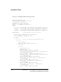
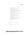
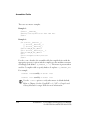
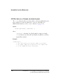
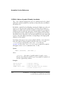
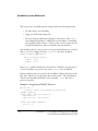
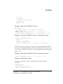
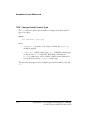
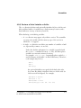
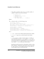
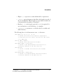
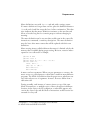
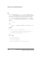
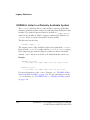
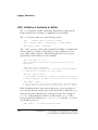
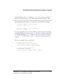
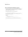
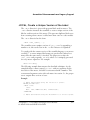
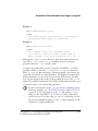
Assembler Enhancements and Legacy Support
.LOCAL, Create a Unique Version of the Label
The .LOCAL directive is given with program labels used in macros. The
.LOCAL directive instructs the assembler to create a unique version of the
label at each invocation of the macro. This prevents duplicate label errors
from occurring when a macro is called more than once in a code module.
The .LOCAL directive has the form:
.LOCAL label_symbol[, … ];
The assembler creates unique versions of label_symbol by appending a
number to it; this can be seen in the .LST file if macros are expanded.
To comply with the current version of the assembly language, you can use
a trailing '?' to ensure unique label names are generated no matter how
many times the same macro is invoked. The preprocessor takes the
label_symbol and postpends _num to it, where num is uniquely generated
for every macro expansion. For example:
abcd? ===> abcd_1
The following example demonstrates the described technique. A code
example declares a macro named getsLabel with one argument. In the
invocation of the macro, the label is concatenated with a number. This
concatenated argument varies with each macro invocation. So, the preprocessor outputs three versions of start.
Example:
// Macro declaration using the release 6.1 syntax:
MACRO getsLabel(%1);
.LOCAL start;
start:
M5=1; I6=1; MODIFY(I6,M4); %1=DM(I6,M5);
.ENDMACRO;
// Macro declaration using the VisualDSP++ 3.5 release syntax:
VisualDSP++ 3.5 Assembler and Preprocessor Manual
for ADSP-218x and ADSP-219x DSPs
3-17
Legacy Directives
#define getsLabel(a) \
start?: \
M5=1; I6=1; MODIFY(I6,M4); a=DM(I6,M5)
// Macro invocation, generate unique labels:
getsLabel(MR1);
getsLabel(MR1);
getsLabel(MR1);
// Macro expansion:
start_1:
M5=1; I6=1; MODIFY(I6,M4); MR1=DM(I6,M5);
start_2:
M5=1; I6=1; MODIFY(I6,M4); MR1=DM(I6,M5);
start_3:
M5=1; I6=1; MODIFY(I6,M4); MR1=DM(I6,M5);
3-18
VisualDSP++ 3.5 Assembler and Preprocessor Manual
for ADSP-218x and ADSP-219x DSPs
Assembler Enhancements and Legacy Support
.MACRO and ENDMACRO, Define a Macro
Macros are created with the assembler’s .MACRO directive. Each statement
within the macro can be an instruction, directive, or macro invocation.
The .ENDMACRO directive marks the end of a macro definition.
A macro definition has the following syntax:
.MACRO macro_symbol[(%1,%2,…,%n)];
…
…
.ENDMACRO;
In the macro’s code, the arguments are marked by the placeholders %1, %2,
%3, etc. When the macro is invoked, the placeholders are replaced by argument values passed in the call. The correct number of arguments must be
passed.
A macro is invoked with its name. The invocation may not contain additional program statements (such as instructions, preprocessor directives, or
other macro invocations) on the same line of source code. When the
macro is called, the arguments passed may be anything from the following
list:
• constant or expression
• symbol (may be any reserved keyword except MACRO, ENDMACRO,
CONST, or INCLUDE)
• expressions with special address pointer (^) and length of (%)
operators
VisualDSP++ 3.5 assembler software has eliminated the .MACRO directive,
although the source programs that use this directive may be re-assembled
with -legacy switch. We recommend that you revise your legacy macro
declarations in order to avoid incompatibility with a future release of the
VisualDSP++ 3.5 Assembler and Preprocessor Manual
for ADSP-218x and ADSP-219x DSPs
3-19
Legacy Directives
DSP development tools. Another way to define macros is with the #define
C preprocessor command. For more information on this command, see
“#define” on page 2-13.
Revise your .MACRO declarations as shown below.
// MACRO declaration using the release 6.1 assembler syntax:
.MACRO getsfirst(%1);
start:
M5=1; I6=1; MODIFY(I6,M4); %1=DM(I6,M5);
.ENDMACRO;
// MACRO declaration using the VisualDSP++ 2.0 release
// assembler syntax:
#define getsfirst(a)\
start:\
M5=1; I6=1; MODIFY(I6,M4); a=DM(I6,M5)
// Macro invocation, common:
getsfirst (MR1);
3-20
VisualDSP++ 3.5 Assembler and Preprocessor Manual
for ADSP-218x and ADSP-219x DSPs
Assembler Enhancements and Legacy Support
.MODULE and .ENDMOD, Declare a Program
Module
The .MODULE directive defines the program module’s name and marks it
beginning, whereas the .ENDMOD directive marks the module’s end. The
assembler stops when it reaches the “end” directive. A source code file may
contain only one program module.
This directive has the form:
.MODULE/qualifier/qualifier moduleSymbol;
where /qualifiers are keywords that define memory type and placement
of a module in the DSP system. Table 3-3 lists valid qualifiers and provides a brief description of each.
Table 3-3. Module Qualifiers
Qualifier
Description
PM or CODE
Memory type — Program Memory.
DM or DATA
Memory type — Data Memory.
RAM
Memory type — Random Access Memory.
ROM
Memory type — Read Only Memory.
ABS=address
Placement of a module at absolute start address.
SEG=secName
Placement of a module in the LDF-declared section secName.
STATIC
A module can not be overwritten during boot page loads.
VisualDSP++ 3.5 Assembler and Preprocessor Manual
for ADSP-218x and ADSP-219x DSPs
3-21
Legacy Directives
• ABS=address
The ABS qualifier places the module’s code at a particular address in
program memory, making it non-relocatable. This means that the
linker is forced to reserve memory for the module at the specified
address. Modules that do not have the ABS qualifier are relocatable.
• SEG=secName
The SEG qualifier locates the module in a specific memory section,
secName, which is declared in the Linker Description File. If you
use both the ABS and SEG qualifiers, and specify an absolute address
which is not in the named section, you will see an error message
when the linker is run.
• STATIC
The
STATIC
qualifier is supported only on ADSP-218x DSPs.
The STATIC qualifier prevents the overwriting of a section when a
boot page is loaded. The linker assures this when it determines the
placement of your program in memory. If a section is not declared
as STATIC, it may be partially or completely overwritten by the
contents of any boot page.
When the linker allocates memory to store your program, it considers nine independent time frames of memory: non-booted
program, data memory, and boot pages 0-7. Non-booted memory
is defined as the initial state of PM and DM before any boot page is
loaded or any code is executed.The code and data of boot page 0
can normally be placed anywhere by the linker, without regard for
any pre-existing memory contents (non-booted values), the code
and data of boot page 1 can be placed anywhere without regard for
the page 0 values, and so on.
and
qualifiers are used only for DSPs with boot
The
memory, which includes all processors of the ADSP-21xx procesBOOT
STATIC
sors (except the ADSP-2100 DSPs).
3-22
VisualDSP++ 3.5 Assembler and Preprocessor Manual
for ADSP-218x and ADSP-219x DSPs
Assembler Enhancements and Legacy Support
Example 1:
.MODULE/PM/ABS=0x0040 main_prog;
…
.ENDMOD;
/* This example declares main_prog which is to be located in
program memory RAM at address 40 (hexadecimal). */
Example 2:
.MODULE/SEG=fir filter_routine;
…
.ENDMOD;
/* This statements declare the relocatable module
filter_routine, located in a memory segment named fir,
which is defined in the linker description file (.ldf). */
Although the .MODULE/.ENDMOD directives have been replaced in the current release, easm218x and easm219x assemblers process your legacy
programs when the -legacy switch is used.
To mark a program memory section using the VisualDSP++ 3.5 release
assembler syntax, you use the .SECTION/PM or .SECTION/CODE directives.
With .SECTION, you have advantage of having multiple code sections in a
source file and control over data placement. The Linker Description File
defines placement of your source sections in the DSP memory. In addition, you can interpret the results of the assembly process via the elfdump
utility. This utility is included in the DSP development kit and allows you
to view the section’s size and variable placement.
more information on the
directive, including syntax
For
and usage examples, see “.SECTION, Declare a Memory Section”
.SECTION
on page 1-67. For information on the .LDF file and the elfdump
utility, see the VisualDSP++ 3.5 Linker and Utilities Manual for
16-Bit Processors. Note that only one .MODULE is allowed per source
file, whereas multiple program SECTION(s) define mapping of code
and data in a single assembly file.
VisualDSP++ 3.5 Assembler and Preprocessor Manual
for ADSP-218x and ADSP-219x DSPs
3-23
Legacy Directives
.PORT, Declare a Memory Mapped Port
The .PORT directive assigns a port name symbol to I/O port. Port name
symbols are global symbols. This port name corresponds to an I/O port
that you define in the Linker Description File.
The .PORT directive uses the following syntax:
.PORT port_name;
The port_name is a port symbol that is globally available.
To declare a port using the ADSP-218x/ADSP-219x assembler syntax,
you use the .VAR directive to declare the port-identifying symbol and the
Linker Description File to create the corresponding I/O section. The
linker resolves port variables in the .LDF file.
For more information on the LDFs, see the VisualDSP++ 3.5 Linker and
Utilities Manual for 16-Bit Processors. For more information on the .VAR
directive, see “.VAR, Declare a Data Variable or Buffer” on page 1-75.
Examples:
// legacy assembly syntax:
.PORT port1;
{declares I/O port port1}
.PORT port2;
{declares I/O port port2}
// current assembly syntax:
3-24
.VAR port1, port2;
{declares two port variables}
.GLOBAL port1, port2;
{global scope variables}
VisualDSP++ 3.5 Assembler and Preprocessor Manual
for ADSP-218x and ADSP-219x DSPs
Assembler Enhancements and Legacy Support
.VAR/ABS, Place a Variable at the Specified
Address
The /ABS qualifier of the .VAR directive places the variable or buffer at a
particular address in program memory or data memory, making it
non-relocatable. This means that the linker is forced to reserve memory
for the variable or buffer at the specified address. Variables and buffers
that do not have the ABS qualifier are relocatable. For more information
on the .VAR directive, see “.VAR, Declare a Data Variable or Buffer” on
page 1-75.
.VAR/CIRC, Declare a Circular Buffer
The .VAR directive declares a liner buffer unless the /CIRC attribute is
applied. The /CIRC qualifier defines the buffer as circular. For more information on the .VAR directive, see “.VAR, Declare a Data Variable or
Buffer” on page 1-75.
The following example declares a relocatable circular buffer whose length
is the value of the constant taps.
.CONST taps=15;
.VAR/DM/CIRC data_buffer[taps];
When multiple variables and buffers are declared on the same line, the
linker places them in contiguous memory locations. If multiple buffers are
declared on one line, and the /CIRC qualifier is used, a single circular
buffer is created—the individual buffers will be simple linear buffers only.
For example, the following declaration creates one 15-word circular
buffer.
.VAR/CIRC aa[5],bb[5],cc[5];
VisualDSP++ 3.5 Assembler and Preprocessor Manual
for ADSP-218x and ADSP-219x DSPs
3-25
Legacy Directives
The base address of the circular buffer is aa; this is the symbol used to
access the buffer in code. The address of bb is aa+5 and the address of cc is
aa+10. The three five-word buffers can be individually accessed as linear
buffers. Since the value 15 requires four bits for binary representation, the
circular buffer aa is located at an address which is a multiple of sixteen.
The following example uses three .VAR directives to declare three different
circular buffers.
.VAR/CIRC aa[5];
.VAR/CIRC bb[5];
.VAR/CIRC cc[5];
This example creates the structure for a
sine/cosine
lookup table.
.VAR/CIRC sin[256],cos[768];
A single circular buffer is defined which has a length of 1024. To access
the buffer in code, you can initialize DAG index registers and buffer length
registers with the following instructions:
I0=^cos;
L0=1024;
I1=^sin;
L1=1024;
/* ^ is the Release 6.1 “address pointer” operator */
These instructions load I0 and I1 with the base addresses of cos and sin.
The corresponding L registers are loaded with the length of the circular
buffer to enable wraparound addressing. A circular buffer is only implemented when an L register is set to a non-zero value.
The following example demonstrate how the assembler operators are used
to load L (length) and I (index) registers when setting up circular buffers.
.SECTION/DATA data1;
.VAR real_data[n];
…
.SECTION/CODE program;
I5=real_data;
3-26
// data section
// n=number of input samples
// code section
// buffer’s base address
VisualDSP++ 3.5 Assembler and Preprocessor Manual
for ADSP-218x and ADSP-219x DSPs
Assembler Enhancements and Legacy Support
L5=length(real_data);
AR=I5;
REG(B5)=AR;
M4=1;
CNTR=DO loop1 UNTIL CE;
AX0=DM(I5,M4);
…
loop1: …
// buffer’s length
// load address to data register
// post-modify I5 by 1
// get next sample
This code fragment initializes I5 and L5 to the base address and length,
respectively, of the circular buffer real_data. The buffer length value contained in L5 determines when addressing wraps around the top of the
buffer.
For more information on circular buffers, refer to the target DSP’s Hardware Reference Manual.
VisualDSP++ 3.5 Assembler and Preprocessor Manual
for ADSP-218x and ADSP-219x DSPs
3-27
Syntax Conventions
Syntax Conventions
The assembler supports numeric bases and comments formats within
expressions and instructions. You build these expressions and instructions
using predefined set of operators and following the assembler’s syntax.
This section contains:
• “Modified Operators”
• “Modified Numeric Conventions”
• “Comment Conventions”
Modified Operators
Syntax for the special “length of”, “address of”, “page of”, and preprocessor’s division operators have changed. Table 3-4 lists modified operators.
Table 3-4. Modified Operators
Release 6.1 Operator
Description
Change for VisualDSP++ 3.5
\
Division
/
%symbol
Length of symbol in words.
LENGTH(symbol)
^symbol
Address pointer to symbol
symbol
PAGE symbol
PAGEOF symbol
Upper address bits of a page
associated with symbol.
PAGE(symbol)
3-28
VisualDSP++ 3.5 Assembler and Preprocessor Manual
for ADSP-218x and ADSP-219x DSPs
Assembler Enhancements and Legacy Support
Modified Numeric Conventions
The format for the hexadecimal numeric base has been modified; the
usage of the “0x” prefix is preferred for hexadecimal numbers. When
assembling programs coded with any of numeric conventions listed in
Table 3-5, select the -legacy switch.
Table 3-5. Hexadecimal Numeric Formats
Release 6.1 Convention
Description
Change for VisualDSP++ 3.5
0x number
H#number
h#number
Hexadecimal base number
formats.
0xnumber
Comment Conventions
The assembler now supports C++-style format for inserting comments in
assembly source code programs:
//comment
— A pair of slashes (/ /) denote each single-line comment.
The following comment formats are legacy formats:!comment — ! begins
each single-line comment.
{ comment }
— a pair of braces “{ }” enclose multiple-line comment.
The current release of development tools allows you to use the -csall,
-cs!, -cs{, -cs//, or -cs/* switch on the assembler’s or on the preprocessor’s command line to select your comment style format.
VisualDSP++ 3.5 Assembler and Preprocessor Manual
for ADSP-218x and ADSP-219x DSPs
3-29
Debugging Capabilities and File Format
The assembler and preprocessor include features that allow for debugging
of your source code programs. These features include the ability to generate binary data in ELF/DWARF-2 file format and to output line number
and the file name of a source file.
ELF File Format
The VisualDSP++ 3.5 assembler creates and supports files in ELF format.
The ELF format is derived from the industry standard ELF Specification.
The ELF binary format provides host independent object representation
and allows for greater flexibility in describing sections.
Object, library, and executable files that were generated by Release 6.1
and prior releases of the tools are in ASCII executable (AEXE) format. If
you are using these files in your project builds or find you are rebuilding
frequently, you might consider converting them into the ELF format.
You can do this using the aexe2elf utility, which is installed in the
ADSP-218x DSP and ADSP-219x DSP code generation packages and
documented in the VisualDSP++ 3.5 Linker and Utilities Manual for
16-Bit Processors. Doing this conversion can potentially save time in your
project development cycles.
Although the aexe2elf utility will convert your AEXE object files to the
ELF object files, it will not convert the AEXE debug information into
DWARF-2. As a result, source files that were previously generated in the
AEXE format must be reassembled or recompiled in ELF in order to be
debugged.
3-30
VisualDSP++ 3.5 Assembler and Preprocessor Manual
for ADSP-218x and ADSP-219x DSPs
Assembler Enhancements and Legacy Support
Debug Information
When assembling your source file, either from a command line or within
the VisualDSP++ environment, you have the option of generating binary
information for source level debugging. You can do it by selecting the -g
command-line switch or checking the Generate debug information check
box in the Assemble tab of the VisualDSP++ environment’s Project
Options dialog box. The ELF assemblers generate debug information in
DWARF-2 format.
For more information on the -g switch, see “-g” on page 1-90. For more
information on the VisualDSP++ environment, see the VisualDSP++ 3.5
User’s Guide for 16-Bit Processors.
You also have the option of outputting the line number and file name of
your original source file from the assembler by using the #line preprocessor command. For more information on the #line command, refer to
“#line” on page 2-25.
VisualDSP++ 3.5 Assembler and Preprocessor Manual
for ADSP-218x and ADSP-219x DSPs
3-31
Debugging Capabilities and File Format
3-32
VisualDSP++ 3.5 Assembler and Preprocessor Manual
for ADSP-218x and ADSP-219x DSPs
A UTILITIES
Your VisualDSP++ 3.5 development software comes with the comment
conversion utility that runs from a command line only. This utility provides support for converting legacy code developed under Release 6.1.
This appendix describes the utility and its command-line interface.
Comment Converter
The comment converter program (commentconverter.exe) takes an
assembler source file and converts legacy comment delimiters to C-style
and C++-style comment delimiters.
When converting comments, all occurrences of "{ }" pair interpreted as
comments are replaced with "/* */" comment delimiters. All occurrences
of "!" interpreted as comments are replaced with "//". The comment converter replaces "{ }" or "!" only when it interpreted as a comment delimiter
in the source file. Other occurrences, such as a comment within another
comment, are not converted.
The conversion utility has the following command line:
C:\Program Files\Analog Devices\VisualDSP>commentconverter
Usage:
commentconverter <inputFilename>
For typical usage, use the -o switch to direct the output:
commentconverter inputFilename.asm -o outputFilename.asm
VisualDSP++ 3.5 Assembler and Preprocessor Manual
for ADSP-218x and ADSP-219x DSPs
A-1
Comment Converter
Additional options can be used to select other comment formats to be
interpreted by the converter. These options appear in the help screen
(-help), as follows in Table A-1.
Table A-1. Commentconverter Command-Line Switches
Convention
-csall
Description
Detects all supported commenting styles:
-cs{
“{ }” style comments
“/* */” style comments
-cs/*
-cs!
"!" style comments
-cs//
“//” style comments
-help
Displays a list of switches
-noinfo
Turns off informational messages
-nowarn
Turns off warning and informational messages
-o filename
Outputs named converted file
-rsall
Replaces “{ }” and “!” style comments
-rs{
Replaces “{ }” style comments
-rs!
Replaces “!” style comments
By default, the comment converter recognizes all comment delimiters
(-csall) and replaces both “{ }” and “!” comment formats (-rs{, rs!).
The -no prefix preceding the cs and rs switches turns off recognition of
commenting styles.
Example:
{ start of a comment
more comment
end of a comment
}
A-2
VisualDSP++ 3.5 Assembler and Preprocessor Manual
for ADSP-218x and ADSP-219x DSPs
Utilities
label: NOP;
// no code here!
! start of a comment {single line}
Once the utility is run with the default options, the example converts to:
/* start of a comment
more comment
end of a comment
*/
label: NOP;
// no code here!
// start of a comment {single line}
VisualDSP++ 3.5 Assembler and Preprocessor Manual
for ADSP-218x and ADSP-219x DSPs
A-3
Comment Converter
A-4
VisualDSP++ 3.5 Assembler and Preprocessor Manual
for ADSP-218x and ADSP-219x DSPs
I
INDEX
Symbols
# (stringization) preprocessor operator
2-29
## (concatenate) preprocessor operator
2-30
#define (macro) preprocessor
command
variable argument list 2-14
% (length of) legacy syntax 3-28
... preprocessor operator 2-14
.ALIGN (address alignment) assembler
directive 1-44
.EDNIF assembly directive 1-34
.ELIF assembly directive 1-34
.ELSE assembly directive 1-34
.END_REPEAT assembler directive
1-65
.EXTERN (global label) assembler
directive 1-46
.EXTERN STRUCT (define struct)
assembler directive 1-47
.FILE (override filename) assembler
directive 1-49
.GLOBAL (global symbol) assembler
directive 1-50
.IF assembly directive 1-34
.INIT and ASCII string initialization
support 3-16
.LEFTMARGIN assembler directive
1-53
.LIST assembler directive 1-54
.LIST_DATA assembler directive 1-55
.LIST_DATFILE assembler directive
1-56
.LIST_DEFTAB (default listing tab
width) assembler directive 1-57
.LIST_LOCTAB (local listing tab
width) assembler directive 1-58
.LIST_WRAPDATA assembler
directive 1-59
.NEWPAGE assembler directive 1-60
.NOLIST assembler directive 1-54
.NOLIST_DATA assembler directive
1-55
.NOLIST_DATFILE assembler
directive 1-56
.NOLIST_WRAPDATA assembler
directive 1-59
.PAGELENGTH assembly directive
1-61
.PAGEWIDTH assembly directive
1-62
VisualDSP++ 3.5 Assembler and Preprocessor Manual
for ADSP-218x and ADSP-219x DSPs
I-1
INDEX
.PREVIOUS assembler directive
1-63
.REPEAT() assembler directive
1-65
.SECTION assembler directive 1-7,
1-67
.STRUCT assembler directive 1-69
.TYPE assembler directive 1-74
.VAR (declare variable) assembler
directive 1-75
.VAR/CIRC qualifier 1-79
.VAR/INIT24 assembler directive
1-79
.VCSE_METHODCALL_END
assembler directive 1-80
.VCSE_METHODCALL_START
assembler directive 1-80
.VCSE_RETURNS assembler
directive 1-80
.WEAK assembler directive 1-81
? preprocessor operator 2-32
^ (address of) legacy syntax 3-28
__ADSP218X__ macro 2-9
__ADSP219X__ macro 2-9
__ADSP21XX__ macro 2-9
__DATE__ macro 2-9
__FILE__ macro 2-9
__LASTSUFFIX__ macro 2-9,
2-33
__LINE__ macro 2-9
__SILICON_REVISION__ macro
1-97
__TIME__ macro 2-9
__VA_ARGS__ identifier 2-15
I-2
_LANGUAGE_ASM macro 2-9
_LANGUAGE_C macro 2-9
A
ABS
absolute placement qualifier 3-25
legacy module qualifier 3-21, 3-22
absolute
address 1-38
circular buffer placement 1-87
ADDRESS () assembler operator
1-29
address alignment 1-44
ADI macro 2-9
ADII environment variable 3-11
-Ao (absolute placement) assembler
switch 1-87
archiver 1-4
arithmetic
fractional 1-32
mixed fractional 1-33
ASCII executable
converting into ELF format 3-30
ASCII string initialization 1-78,
3-16
assembler
command line syntax 1-83
command-line switch
-Ao (absolute placement) 1-87
-c (case sensitive) 1-87
-D (define macro) 1-88
-D option 1-89
-flags-compiler 1-88
-flags-pp 1-90
VisualDSP++ 3.5 Assembler and Preprocessor Manual
for ADSP-218x and ADSP-219x DSPs
INDEX
-g (generate debug info) 1-90
-h (help) 1-91
-i (include path) 1-91
-I option 1-89
-l (listing) switch 1-92
-legacy (accept legacy code)
1-92
-li (listing with include) switch
1-92
-M (make rule only) 1-93
-MM (make rule and assemble)
1-94
-Mo (output make rule) 1-94
-Mt (make rule for named file)
1-93
-o (output) 1-94
-pp (proceed with preprocessing) 1-95
-proc processor 1-95
-proc processorID 1-96
-si-revision version (silicon revision) 1-96
-sp (skip preprocessing) 1-97
-v (verbose) 1-97
-version (display version) 1-97
-w (skip warning messages) 1-98
-wnumber (warning suppression) 1-98
command-line syntax 1-83
directive syntax 1-6, 1-40
directives 1-40
expressions, constant and address
1-27
file extensions 1-84
instruction set 1-6
keywords 1-19
legacy directives 3-4…3-27
numeric bases 1-30
operator precedence chart 1-28
operators 1-28
program content 1-6
run-time environment 1-2
source files
(.ASM) 1-4
special operators 1-29
symbols 1-25
assembler directives
.ALIGN 1-44
.END_REPEAT 1-65
.EXTERN 1-46
.EXTERN STRUCT 1-47
.FILE 1-49
.GLOBAL 1-50
.IMPORT 1-51
.LEFTMARGIN 1-53
.LIST 1-54
.LIST_DATA 1-55
.LIST_DATFILE 1-56
.LIST_DEFTAB 1-57
.LIST_LOCTAB 1-58
.LIST_WRAPDATA 1-59
.NEWPAGE 1-60
.NOLIST 1-54
.NOLIST_DATA 1-55
.NOLIST_DATFILE 1-56
.NOLIST_WRAPDATA 1-59
.PAGELENGTH 1-61
.PAGEWIDTH 1-62
VisualDSP++ 3.5 Assembler and Preprocessor Manual
for ADSP-218x and ADSP-219x DSPs
I-3
INDEX
.PREVIOUS 1-63
.REPEAT() 1-65
.SECTION 1-67
.STRUCT 1-69
.TYPE 1-74
.VAR 1-75
.VAR/INIT24 1-79
.VCSE_METHODCALL_END
1-80
.VCSE_METHODCALL_STAR
T 1-80
.VCSE_RETURNS 1-80
.WEAK 1-81
assembly directives
conditional 1-34
assembly language constant 2-39
B
built-in functions
OFFSETOF() 1-36
SIZEOF() 1-37
C
-c (case sensitive) assembler switch
1-87
C and assembly, interfacing 1-12
case-sensitive mode 1-87
CIRC, declaring a circular buffer
3-25
circular buffers 3-25
ADSP-219x processors 1-29
CODE
section/memory type 1-67, 3-21
comma-separated option 1-90
I-4
comment converter A-1
default options A-2
commentconverter
command-line switches
-csall (detects all comments) A-2
-help (displays help screen) A-2
-no (disables recognition of cs/rs
styles) A-2
-noinfo (disables info messages)
A-2
-nowarn (disables warnings) A-2
-o filename (outputs named file)
A-2
-rs! (replaces "!" comments) A-2
-rs{ (replaces "{}" comments)
A-2
-rsall (replace all comments) A-2
concatenate (##) preprocessor
operator 2-30
conditional assembly directives
.ELIF 1-34
.ELSE 1-34
.ENDIF 1-34
.IF 1-34
CONST (constant declaration)
legacy directive 3-6
constant expression 1-27
conventions
comment strings 1-33
file extensions 1-84
file names 1-83
numeric formats 1-30
user-defined symbols 1-25
conventions, of this manual -xvii
VisualDSP++ 3.5 Assembler and Preprocessor Manual
for ADSP-218x and ADSP-219x DSPs
INDEX
-cpredef (C-style definitions)
preprocessor switch 2-37
-cs! ("!" comment style)
preprocessor switch 2-38
-cs/* ("/* */" comment style)
preprocessor switch 2-38
-cs// ("//" comment style)
preprocessor switch 2-38
-cs{ ("{}" comment style)
preprocessor switch 2-38
-csall (all comment styles)
preprocessor switch 2-38
-cstring (C style) preprocessor
switch 2-37
custom processors 1-95
customer support -xi
D
-D (define macro) assembler switch
1-88
-D (define macro) preprocessor
switch 2-39
-D assembler switch option, see
-flags-compiler switch 1-89
-D__ADSP2181__ macro 1-15
-D__ADSP218X__ macro 1-15
-D__ADSP2191__ macro 1-15
-D__ADSP219X__ macro 1-15
-D__ADSP21XX__ macro 1-15
-D_LANGUAGE_ASM macro
1-15
DAG index registers 3-26
DATA
section/memory type 3-21
data
initialization files listing 1-56
placement 3-23
data buffer
declaring and initializing 1-75
initializing 1-75
debugging
information) 1-90
source level 3-31
debugging capabilities 3-30
default
defines 1-89
symbol type 1-74
tab width 1-57, 1-58
define (macro) preprocessor
command 2-13
variable argument list 2-14
defines options 1-89
directives
preprocessing 1-35
DM
section/memory type 3-21
DM or DATA, section & memory
type 1-67
DMSEG (locate data) legacy
directive 3-7
DWARF-2 format 3-30
E
ELF
binary file format 3-30
symbol types 1-74
ELF.h 1-74
elif preprocessor command 2-16
VisualDSP++ 3.5 Assembler and Preprocessor Manual
for ADSP-218x and ADSP-219x DSPs
I-5
INDEX
else (alternate instruction)
preprocessor command 2-17
endif (termination) preprocessor
command 2-18
ENDMACRO legacy directive 3-19
ENDMODULE legacy directive
3-21
ENTRY (program label) legacy
directive 3-9
error (error message) preprocessor
command 2-19
expressions
address 1-27
constant 1-27
EXTERN (global label) assembler
directive 1-47
EXTERNAL (global data symbol)
legacy directive 3-10
F
feature assembler macros 1-15
feature preprocessor macros
__ADSP218X__ 2-9
__ADSP219X__ 2-9
__ADSP21XX__ 2-9
_LANGUAGE_ASM 2-9
_LANGUAGE_C 2-9
file extensions
.ASM (assembly source) 1-3
.DAT (data file) 1-3
.DLB (library file) 1-4
.DOJ (object file) 1-3
.H (header file) 1-3
.IS (preprocessed assembly file)
I-6
1-95
file formats
ELF (Executable and Linkable
Format) 1-3
file initialization
array 1-78
file naming conventions 1-83
-flags-compiler assembler switch
1-89
-flags-pp assembler switch 1-90
formats, numeric 1-30
fractional constants 1-32
fracts
1.0r special case 1-32
1.15 format 1-31
constants 1-31
mixed type arithmetic 1-33
G
-g (generate debug info) 1-90
generating unique labels 2-32
global substitutions 2-4
H
-h (help) assembler switch 1-91,
2-39
header files 2-4
system 2-4
tokens 2-5
user 2-5
I
-i (include directory) preprocessor
switch 2-39
VisualDSP++ 3.5 Assembler and Preprocessor Manual
for ADSP-218x and ADSP-219x DSPs
INDEX
-i (include path) assembler switch
1-91
-I (include search-path)) assembler
options 1-90
-I- (system include files)
preprocessor switch 2-40
-I assembler switch option, see
-flags-compiler switch 1-90
if (test if true) preprocessor
command 2-20
ifdef (test if defined) preprocessor
command 2-21
ifndef (test if not defined)
preprocessor command 2-22
IMPORT assembler directive 1-51
IMPORT header files 1-51
IMPORT headers
make dependencies 1-17
include
path search 2-6
system header files 2-4
user header files 2-4
INCLUDE (include file) legacy
directive 3-11
include (insert a file) preprocessor
command 2-23
INDENT (indent lst file) legacy
directive 3-13
INIT and INIT24 (initialize
symbols) legacy directive 3-14
input section alignment instruction
1-44
instruction set 1-6
L
-l (listing) assembler switch 1-92
-legacy (accept legacy code)
assembler switch 1-92
legacy /qualifier
/ABS 3-22
/SEG 3-22
/STATIC 3-22
legacy directives
.CONST 3-6
.DMSEG 3-7
.ENTRY 3-9
.EXTERNAL 3-10
.INCLUDE (include file) 3-11
.INIT and .INIT24 (initialize
symbols) 3-14
.LOCAL (unique label version)
3-17
.MACRO and .ENDMACRO
3-19
.MODULE and
.ENDMODULE 3-21
.PMSEG 3-7
.PORT 3-24
INDENT (indent lst file) 3-13
LENGTH () assembler operator
1-29
-li (listing with include) assembler
switch 1-92
line (output line number)
preprocessor command 2-25
linker 1-4
Linker Description File 1-7
listing files
VisualDSP++ 3.5 Assembler and Preprocessor Manual
for ADSP-218x and ADSP-219x DSPs
I-7
INDEX
address 1-18
assembly process information 1-4
assembly source code 1-18
C data structure information 1-4
data initialization 1-56
data opcodes 1-55
large opcodes 1-59
line number 1-18
named 1-92
opcode 1-18
producing 1-4
listing files (.LST) 1-4, 1-18
LOCAL (unique label version)
legacy directive 3-17
local tab width 1-57, 1-58
long-form initialization 1-69, 1-70
loop unrolling 1-65
M
-M (make rule only) assembler
switch 1-93
-M (make rule only) preprocessor
switch 2-41
macro expansion
tokens 2-5
MACRO legacy directive 3-19
macros
feature assembler 1-15
feature preprocessor 2-8
predefined preprocessor 2-8
preprocessor feature 2-8
variable length argument list 2-14
writing 2-6
make dependencies 1-51
I-8
generating 1-17
memory
section declaring 1-67
types 1-7
memory type
DM (DATA) 1-67, 3-21
PM (CODE and DATA) 1-67
PM (CODE) 1-67, 3-21
RAM 3-21
ROM 3-21
-MM (make rule and assemble)
assembler switch 1-93
-MM (make rule and assemble)
preprocessor switch 2-40, 2-41
-Mo (output make rule) assembler
switch 1-94
-Mo (output make rule)
preprocessor switch 2-41
MODULE legacy directive 3-21
module qualifier
ABS 3-21
SEG 3-21
STATIC 3-21
-Mt (output make rule for named
file) assembler switch 1-94
-Mt preprocessor switch 2-42
N
nested
struct definition 1-38
struct reference 1-38
-nowarn preprocessor switch 2-43
numeric formats 1-30
VisualDSP++ 3.5 Assembler and Preprocessor Manual
for ADSP-218x and ADSP-219x DSPs
INDEX
O
-o (output) assembler switch 1-94
-o (output) preprocessor switch
2-42
object file
producing 1-4
object files (.DOJ) 1-4
OFFSETOF() built-in function
1-36
operator
assembler 1-28
length of 1-29
symbol 1-29
operator, modified 3-28
P
padding bytes 1-38
PAGE (page of) legacy operator
3-28
PAGE() operator 1-30
PAGE(symbol) assembler operator
1-29
PM
section/memory type 1-67, 3-21
PMSEG (locate code & data) legacy
directive 3-7
PORT legacy directive 3-24
-pp (proceed with preprocessing)
assembler switch 1-95
pragma preprocessor command
2-26
predefined preprocessor macros
__DATE__ 2-9
__FILE__ 2-9
__LASTSUFFIX__ 2-9
__LINE__ 2-9
__TIME__ 2-9
ADI 2-9
preprocessed
assembly files 2-11
source file 2-11
preprocessing
directives 1-35
program 1-14
preprocessor
command syntax 1-7, 2-11
command, list of 2-11
command-line switches 2-35
-cpredef 2-37
-cs! 2-38
-cs/* ("/* */" comment style)
2-38
-cs// ("//" comment style) 2-38
-cs{ ("{}" comment style) 2-38
-csall (all comment styles) 2-38
-cstring (C style) 2-37
-D (define macro) 2-39
-h (help) 2-39
-i (include path) 2-39
-I- (search system include files)
2-40
-M (make rule only) 2-41
-MM (make rule and assemble)
2-41
-Mo (output make rule) 2-41
-Mt (output make rule for
named file) 2-42
-notokenize-dot 2-42
VisualDSP++ 3.5 Assembler and Preprocessor Manual
for ADSP-218x and ADSP-219x DSPs
I-9
INDEX
-nowarn 2-43
-o (output) 2-42
-stringize 2-42
-tokenize-dot 2-42
-v (verbose) 2-43
-version (display version) 2-43
-w (skip warning messages) 2-43
-warn (print warnings) 2-43
-Wnumber (warning suppression) 2-43
command-line syntax 2-34
compiler 2-2
feature macros 2-8
global substitutions 2-4
guide 2-2
option settings 2-10
overview 2-1
predefined macros 2-8
system header file 2-23
user header file 2-23
writing commands in 2-3
preprocessor commands 2-11
#define 2-13
#elif 2-16
#else 2-17
#endif 2-18
#error 2-19
#if 2-20
#ifdef 2-21
#ifndef 2-22
#include 2-23
#line (counter) 2-25
#pragma 2-26
#undef 2-27
I-10
#warning 2-28
preprocessor operators
# (stringization) 2-29
##concatenate 2-30
? (generate unique label) 2-32
-proc (target processor) assembler
switch 1-95
program
assembling 1-4
content 1-6
listing files 1-18
preprocessing 1-14
structure 1-7
writing assembly 1-3
Project Options settings
assembler 1-99
preprocessor 2-10
R
RAM
section/memory type 3-21
repeating an instruction sequence
1-65
RESOLVE() linker command 1-81,
1-87
ROM
section/memory type 3-21
S
section qualifier
DM (DATA) 1-67, 3-21
PM (CODE) 1-67, 3-21
RAM 3-21
ROM 3-21
VisualDSP++ 3.5 Assembler and Preprocessor Manual
for ADSP-218x and ADSP-219x DSPs
INDEX
sectionTypes identifier 1-68
SEG
legacy module qualifier 3-22
SEG, legacy module qualifier 3-22
settings
assembler options 1-99
from command line 1-82
from VisualDSP++ IDDE
1-100
default tab width 1-57
local tab width 1-58
preprocessor options
from command line 2-10
from VisualDSP++ IDDE 2-10
through build tools 2-10
short-form initialization 1-69
SHT_PROGBITS identifier 1-68
silicon revision setting 1-96
-si-revision (silicon revision)
assembler switch 1-96
SIZEOF() built-in function 1-37
source files
(.ASM) 1-4
-sp (skip preprocessing) assembler
switch 1-97
special characters
dot 1-26
STATIC qualifier 3-22
STATIC, legacy module qualifier
3-22
string initialization 1-78
stringization operator 2-29, 2-42
-stringize (double quotes)
preprocessor switch 2-42
struct references 1-38
nested 1-38
STT_FUNC symbol type 1-74
STT_OBJECT symbol type 1-74
switches (see assembler
command-line switch)
symbol
assembler operator 1-29
conventions 1-26
symbolic expressions 1-27
symbols (see assembler symbols)
syntax
assembler command line 1-83
assembler directives 1-40
constants 1-27
instruction set 1-6
macro 2-6
preprocessor command 2-11
system header files 2-4
T
tab
characters 1-57
characters in source file 1-58
-tokenize-dot (identifier parsing)
preprocessor switch 2-42
tokens
macro expansion 2-5
TYPE (symbol type) assembler
directive 1-74
U
undef (undefine) preprocessor
command 2-27
VisualDSP++ 3.5 Assembler and Preprocessor Manual
for ADSP-218x and ADSP-219x DSPs
I-11
INDEX
unique labels 2-32
user header files 2-4
Utility
comment conversion A-1
V
-v (verbose) assembler switch 1-97
-v (verbose) preprocessor switch
2-43
VAR/CIRC, declaring a circular
buffer 3-25
variable length argument list 2-14
variables
initializing 1-75
VCSE optimization directives 1-80
-version (display version) assembler
switch 1-97
-version (display version)
preprocessor switch 2-43
VisualDSP++
assembler settings 1-100
assembling from 1-3
I-12
preprocessor settings 2-10
Project Options dialog box 1-19
W
-w (skip warning messages)
assembler switch 1-98
-w (skip warning messages)
preprocessor switch 2-43
-warn (print warnings) preprocessor
switch 2-43
warning (warning message)
preprocessor command 2-28
warning suppression 2-43
warnings
printing 2-43
weak symbol binding 1-81
-wnumber (warning suppression)
assembler switch 1-98
-Wnumber (warning suppression)
preprocessor switch 2-43
wrapping opcode listings 1-59
writing assembly programs 1-3
VisualDSP++ 3.5 Assembler and Preprocessor Manual
for ADSP-218x and ADSP-219x DSPs
INDEX
VisualDSP++ 3.5 Assembler and Preprocessor Manual
for ADSP-218x and ADSP-219x DSPs
I-13
INDEX
I-14
VisualDSP++ 3.5 Assembler and Preprocessor Manual
for ADSP-218x and ADSP-219x DSPs
INDEX
VisualDSP++ 3.5 Assembler and Preprocessor Manual
for ADSP-218x and ADSP-219x DSPs
I-15
INDEX
I-16
VisualDSP++ 3.5 Assembler and Preprocessor Manual
for ADSP-218x and ADSP-219x DSPs