1
JMA-9172-SA
MARINE RADAR
EQUIPMENT
INSTRUCTION
MANUAL
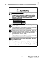
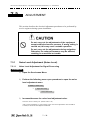
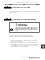
◆◆◆ PRECAUTIONS BEFORE OPERATION ◆◆◆
■ Cautions for high voltage
High voltages from hundreds volts to tens of thousands volts are to be applied to
the electronic equipment such radio and radar devices. You do not face any
danger during normal operation, but sufficient cares are required for maintenance,
inspection and adjustment of their internal components. (Maintenance, check-up
and adjustment of the inside of the equipment are prohibited except by
maintenance specialists.)
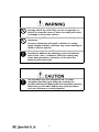
High voltages of tens of thousands volts are so dangerous as to bring an
instantaneous death from electric shock, but even voltages of hundred volts may
sometimes lead to a death from electric shock. To prevent such an accident, make
it a rule to turn off the power switch, discharge capacitors with a wire surely
earthed on an end make sure that internal parts are no longer charged before you
touch any parts inside these devices. At the time, wearing dry cotton gloves
ensures you further to prevent such danger. It is also a necessary caution to put
one of your hands in the pocket and not to use your both hands at the same time.
It is also important to select a stable foothold always to prevent additional injuries
once you were shocked by electricity. If you were injured from electric shock,
disinfect the burn sufficiently and get it taken care of promptly.
■ What to do in case of electric shock
When finding a victim of electric shock, turn off the power source and earth the
circuit immediately.
If it is impossible to turn off the circuit, move the victim away promptly using
insulators such as dry wood plate and cloth without touching the victim directly.
In case of electric shock, breathing may stop suddenly if current flows to the
respiration center in the brain. If the shock is not so strong, artificial respiration
may recover breathing. When shocked by electricity, the victim will come to look
very bad with weak pulse or without beating, resulting in unconsciousness and
rigidity. In this case, it is necessary to perform an emergency measure
immediately.
i
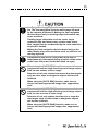
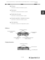
◆◆◆ FIRST-AID TREATMENTS ◆◆◆
☆ First-aid treatments
As far as the victim of electric shock is not in dangerous condition, do not move
him and practice artificial respiration on him immediately. Once started, it should
be continued rhythmically.
(1)
Do not touch the victim confusedly as a result of the accident, but the
rescuer may also get an electric shock.
(2)
Turn off the power source calmly and move the victim away quietly from
the electric line.
(3)
Call a physician or ambulance immediately or ask someone to call a doctor.
(4)
Lay the victim on this back and loosen his necktie, clothes, belt, etc.
(5)
a.
Examine the victim's pulse.
b.
Examine his heartbeat bringing your ear close to his heart.
c.
Examine his breathing bringing the back of your hand or your face
close to his face.
d.
Check the size of the pupils of his eyes.
(6)
Open the victim's mouth and take out artificial teeth, cigarette or chewing
gum if any. Keep his mouth open, stretch his tongue and insert a towel or
the like in his mouth to prevent the tongue from suffocating. (If it is hard to
open his mouth due to set teeth, open it with a screwdriver and insert a towel
in this mouth.)
(7)
Then, wipe his mouth so that foaming mucus does not accumulate inside.
ii
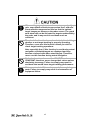
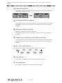
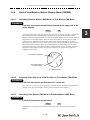
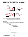
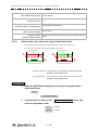
☆ When pulse is beating but breathing has stopped
(Mouth-to-mouth respiration) Fig 1.
(1)
Tilt the victim's head back as far as this face looks back. (A pillow may be
inserted his neck.)
(2)
Push his jaw upward to open his throat wide (to spread his airway).
(3)
Pinch the victim's nostrils and take a deep breath, block his mouth
completely with yours and blow into his mouth strongly. Take a deep breath
again and blow into his mouth. Continue this 10 to 15 times a minutes
(blocking his nostrils).
(4)
Carefully watch that he has recovered his natural breathing and atop
practicing artificial respiration.
(5)
If it is difficult to open the victim's mouth, insert a rubber or vinyl tube into
one of his nostrils and blow into it blocking the other nostril and his mouth
completely.
(6)
When the victim recovers consciousness, he may try to stand up suddenly,
but let him lie calmly and serve him with a cup of hot coffee or tea and keep
him warm and quiet. (Never give him alcoholic drinks.)
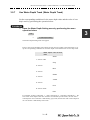
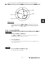
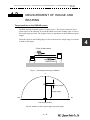
Method of mouth-to-mouth respiration by raising hea
(1)Raise the victim's head. Support
his forehead with one of your hand
and his neck with the other hand. 1
When you tilt his head backward, the
victim, in most cases, opens his
mouth to the air. This makes mouthto mouth respiration easy.
(2)Cover his mouth as widely as
possible with yours and press your
cheek against his nose 2
or, pinch his nostrils with your fingers
to prevent air from leaking. 3
(3)Blow into his lungs.
Continue
blowing into his mouth until his breast
swells. Blow into his mouth as quickly
as possible for the first 10 times.
Fig 1. Mouth-to mouth respiration
iii
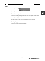
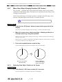
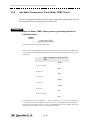
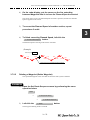
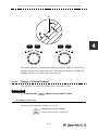
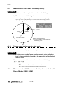
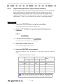
☆ When both pulse and breathing have stopped
Perform the (Cardiac massage) Fig 2. and (Mouth-to-mouth respiration) Fig 1.
When no pulse has come not to be felt, his pupils are open and no heartbeat is
heard, cardiac arrest is supposed to have occurred and artificial respiration must
be performed.
(1)
Place your both hands, one hand on the other, on the lower one third area of
his breastbone and compress his breast with your elbows applying your
weight on his breast so that it is dented about 2cm (Repeat compressing his
breast 50 times or so a minutes). (Cardiac massage)
(2)
In case of one rescuer,
Repeat cardiac massages about 15 times and blow into his mouth 2 times
quickly, and repeat this combination.
In case of two rescuers,
One person repeats cardiac massages 15 times while the other person blow
into his mouth twice, and they shall repeat this combination. (Perform the
cardiac massage and mouth-to-mouth respiration)
(3)
Examine his pupils and his pulse sometimes. When the both have returned
to normal, stop the artificial respiration, serve him with a cup of hot coffee
or tea and keep him warm and calm while watching him carefully. Commit
the victim to a medical specialist depending on his condition. (Never give
him alcoholic drinks.) To let him recover from the mental shock, it is
necessary for persons concerned to understand his situations and the
necessary treatment.
Fig 2. Cardiac massage
iv
PREFACE
Thank you very much for purchasing the JRC marine radar equipment, JMA9172-SA.
This equipment is a marine radar equipment designed to obtain safe operation of
marine ships.
This equipment consists of a radar signal transmitter-receiver unit, a LCD display
unit and a scanner unit as its main units.
• Before operating the equipment, be sure to read this instruction manual
carefully for correct operation.
• Maintain this instruction manual so that operators can refer to it at anytime.
Refer to this manual when any inconvenience or defect occurs.
v
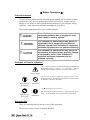
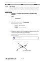
● Before Operation ●
Pictorial Indication
Various pictorial indications are included in this manual and are shown on these
equipment so that you can operate them safety and correctly and prevent any
danger to you and/or to other persons and any damage to your property during
operation. Such indications and their meanings are as follows.
Please understand them before you read this manual:
This indication is shown where incorrect
equipment operation due to negligence may
cause death or serious injuries.
This indication is shown where any person is
supposed to be in danger of being killed or
seriously injured if this indication is neglected
and these equipment are not operated correctly.
This indication is shown where any person is
supposed to be injured or any property damage
is supposed to occur if this indication is
neglected and these equipment are not
operated correctly.
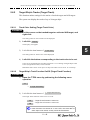
Examples of Pictorial Indication
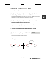
The △ mark represents CAUTION (including DANGER and
WARNING).Detailed contents of CAUTION ("Electric
Shock" in the example on the left.) is shown in the mark.
Electric Shock
The
mark represents prohibition. Detailed contents of the
prohibited action “Disassembling
(
Prohibited”in the example
on the left.) is shown in the mark.
Disassembling
Prohibited
Prohibited
!
Disconnect the
power plug
The
mark represents instruction.
Detailed contents of the instruction (“Disconnect the power
plug “ in the example on the left.) is shown in the mark.
Instruction
Warning Label
There is a warning label on the top cover of the equipment.
Do not try to remove, break or modify the label.
vi
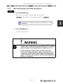
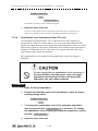
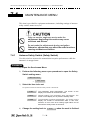
● PRECAUTIONS ●
Never conduct inspection or repair work of equipment
components.
Inspection or repair work by uncertified personnel may
result in fire hazard or electrocution.
For inspection and repair work of equipment
components, consult with our branch office, branch
shop, sales office, or our distributor in your district.
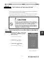
!
When conducting maintenance, make sure to turn the
main power off.Failure to comply may result in
electrocution.
!
Turn off the main power before cleaning the equipment.
Especially when a rectifier is used, make sure to turn it
off since voltage is still outputted from the rectifier even
after the indicator and the radar are turned off. Failure to
comply may result in equipment failure, or death or
serious injury due to electric shock.
!
When conducting maintenance work on the scanner,
make sure to turn its main power off.Failure to comply
may result in electrocution or injuries.
vii
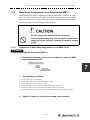
!
Make sure to turn off the scanner safety switch. Failure to
comply may result in injuries caused by physical contact
with the rotating scanner.
Never directly touch the internal components of the
scanner or indicator. Direct contact with these highvoltage components may cause electrocution. For
maintenance, inspection, or adjustment of equipment
components, consult with our branch office, branch
shop, sales office, or our distributor in your district.
To contact our sales department, branch offices, branch
shops, and sales offices:
Please refer to the "Office List" at the end of the
document.
Do not get close to the radiant section of the scanner. It
is a rotating part, and it may cause injuries if it suddenly
starts rotating and consequently hits the body. It is
recommended that the radiant section be installed at a
high place such as on the roof of the wheelhouse, on the
flying bridge, on the trestle, or on the radar mast so that
no one can get close to it. When any work must be done
on the scanner, make sure to turn the safety switch off.
viii
Microwave radiation level:
Keep away from a scanner when it is transmitting.
The high level of microwave is radiated from the front
face of the scanner specified below. The microwave
exposure at close range could result in injuries
(especially of the eyes).
Microwave radiation level
System 10 W/m2
NKE-1532 10cm
!
Make sure to install the scanner at a place higher than
human height.
!
Direct exposure to electromagnetic waves at close range
will have adverse effects on the human body. When it is
necessary to get close to the scanner for maintenance or
inspection purposes, make sure to turn the indicator
power switch to "OFF" or "STBY."
Direct exposure to electromagnetic waves at close range
will have adverse effects on the human body.
Direct exposure to electromagnetic waves at close range
will have adverse effects on the human body.
!
When conducting maintenance work, make sure to turn
off the power so that the power supply to the equipment
is completely cut off.
Some equipment components can carry electrical current
even after the power switch is turned off, and conducting
maintenance work without unplugging the power
connector may result in electrocution, equipment failure,
or accidents.
ix
When cleaning the display screen, do not wipe it too
strongly with a dry cloth. Also, do not use gasoline or
thinner to clean the screen. Failure to comply will result
in damage to the screen surface.
Do not change MBS Level/Area unless absolutely
necessary.
Incorrect adjustment will result in deletion of nearby
target images and thus collisions may occur resulting in
death or serious injuries.
!
When disposing of used lithium batteries, be sure to
insulate the batteries by attaching a piece of adhesive
tape on the + and - terminals. Failure to comply may
cause heat generation, explosion, or fire when the
batteries get shorted out.
!
Use the radar only as a navigation aid. The final
navigation decision must always be made by the
operator him/herself. Making the final navigation decision
based only on the radar display may cause accidents
such as collisions or running aground.
x
!
Use Target Tracking (TT) function only as a navigation
aid. The final navigation decision must always be made
by the operator him/herself. Making the final navigation
decision based only on tracking target information may
cause accidents.
Tracking target information such as vector, target
numerical data, and alarms may contain some errors.
Also, targets that are not detected by the radar cannot be
acquired or tracked.
Making the final navigation decision based only on the
radar display may cause accidents such as collisions or
running aground.
!
A malfunction may occur if the power in the ship is
instantaneously interrupted during operation of the radar.
In this case, the power should be turned on again.
When using the [AUTO SEA] function, never set the
suppression level too high canceling out all image noises
from the sea surface at close range.
Detection of not only echoes from waves but also targets
such as other ships or dangerous objects will become
inhibited.
When using the [AUTO SEA] function, make sure to
choose the most appropriate image noise suppression
level.
When using the [AUTO RAIN] function, never set the
suppression level too high canceling out all image noises
from the rain or snow at close range.
Detection of not only echoes from the rain or snow but
also targets such as other ships or dangerous objects
will become inhibited.
When using the [AUTO RAIN] function, make sure to
choose the most appropriate image noise suppression
level.
xi
!
When setting a guard zone, make sure to properly adjust
gain, sea-surface reflection suppression level, and rain/
snow reflection suppression level so that the optimal
target images are always on the radar screen. The guard
zone alarm will not be activated for targets undetected by
the radar, and it may result in accidents such as
collisions.
The simulation function is used exclusively for deciding
whether or not target tracking is properly operating.
Therefore, never use this function unless you wish to
check target tracking operations.
Note especially that, if this function is used during actual
navigation, simulated targets are displayed and may
become confused with other actual targets. Therefore,
never use this function during actual navigation.
Optimal values have been set for VD LEVEL and
CONSTANT; therefore, never change their values unless
absolutely necessary. Failure to comply may result in
accidents that would lower target tracking performance.
!
Make sure to shut off the main power before replacing
parts. Failure to comply may result in electrocution or
equipment failure.
xii
!
Make sure that two or more staff member work together
when replacing the LCD. If only one person attempts to
replace the LCD, he/she may drop it and become injured.
Do not directly touch the inverter circuit of the LCD
display with a bare hand since high voltage temporarily
remains in the circuit even after the main power is shut
off.
Failure to comply may result in electrocution.
Any adjustments must be made by specialized service
personnel.
Incorrect settings may result in unstable operation.
Do not make any adjustments during navigation. Failure
to comply may result in adverse effects on the radar
function which may lead to accidents or equipment
failure.
Any adjustments must be made by specialized service
personnel.
Failure to comply may result in accidents or equipment
failure.
Do not make any adjustments during navigation. Failure
to comply may result in adverse effects on the radar
function which may lead to accidents or equipment
failure.
Do not change the quantization level settings unless
absolutely necessary. If set at an inappropriate value, the
target acquisition or target tracking function deteriorates,
and this may lead to accidents.
xiii
The Mounting Point of the Warning Label
Warning Label
NCD-9170 Display Unit
Warning Label
Front face
Back face
NWZ-178 Monitor Unit
xiv
Warning Label
NDC-1478 Radar Process Unit
(Desktop Type)
xv
Warning
Label
NQE-3141-4A/8A Interswitch Unit
xvi
xvii
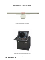
EQUIPMENT APPEARANCE
Scanner Unit Type NKE-1532 (12 feet)
Display Unit Type NCD-9170 (Stand alone type)
xviii
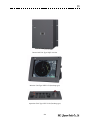
Interswitch Unit Type NQE-3141-4A
Monitor Unit Type NWZ-178 (Desktop type)
Operation Unit Type NCE-5322 (Desktop type)
xix
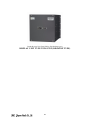
Radar Process Unit Type NDC-1478 (Desktop type)
DISPLAY UNIT TYPE NCD-9170T (DESKTOP TYPE)
xx
GLOSSARY
This section describes the main terms used for this equipment and general related
maritime terms.
A
AZ
Acquisition/Activation zone
A zone set up by the operator in which the system should
automatically acquire radar targets and activate reported AIS targets
when entering the zone.
Activated target
A target representing the automatic or manual activation of a
sleeping target for the display of additional information.
AIS
Automatic Identification System
A system which enables ships and shore stations to obtain
identifying and navigation information about other ships at sea,
using an automated transponder.
Anti-clutter rain
Rain/snow clutter suppression.
Anti-clutter sea
Sea clutter suppression.
Associated target A target simultaneously representing a tracked target and a reported
AIS target having similar parameters (position, course, speed)
which comply with an association algorithm.
AZI
AZImuth stabilization mode
B
BCR/BCT
Bow Crossing Range/Bow Crossing Time
C
C up
Course up
Own ship's course is pointed to the top center of the radar display.
CCRP
Consistent Common Reference Point
A location on own ship, to which all horizontal measurements such
as target range, bearing, relative course, relative speed, CPA or
TCPA are referenced, typically the conning position of the bridge.
Clutter
Unwanted reflections on a radar screen, from sea surface, rain or
snow.
COG
Course Over Ground
The direction of the ship's movement relative to the earth, measured
on board the ship, expressed in angular units from true north
CORREL
CORRELation
xxi
CPA/TCPA
The distance to the Closest Point of Approach/Time to the Closest
Point of Approach.
Limits are set by the operator and are related to own ship.
CTW
Course Through Water
The direction of the ship's movement through the water
D
DRIFT
The current velocity for manual correction or the current speed on
the horizontal axis of the 2-axis log is displayed.
E
EBL
Electronic Bearing Line
An electronic bearing line originated from own ship's position.
ETA
Estimated Time of Arrival
G
Ground
stabilization
A display mode in which speed and course information are referred
to the ground, using ground track input data.
H
HDG
Heading
The horizontal direction that the bow of a ship is pointing at any
instant, expressed in angular units from a reference direction.
HL
Heading line
A graphic line on a radar presentation drawn from the consistent
common reference point to the bearing scale to indicate the heading
of the ship .
HSC
High Speed Craft
Vessels which comply with the definition in SOLAS for high speed
craft
H up
Head up
Own ship's heading line is always pointed to the top center of the
radar display.
I
IMO
International Maritime Organisation
IR
RADAR Interference Rejector
ISW
A device to switch over two or more radar display units and two or
more scanners.
L
xxii
Lost AIS target
A target symbol representing the last valid position of an AIS target
before the reception of its data was lost, or its last dead-reckoned
position.
Lost tracked
target
One for which target information is no longer available due to poor,
lost or obscured signals.
LP
Long Pulse
M
MMSI
Maritime Mobile Service Identity
MOB
Man OverBoard
MON
Performance monitor
MP
Medium Pulse
N
NM
1nm=1852m
N up
North up
P
PI
Parallel Index line
Past positions
Equally time-spaced past position marks of a tracked or AIS target
and own ship.
POSN
POSitioN
PRF
Pulse Repetition Frequency
The number of radar pulses transmitted each second.
PROC
PROCess
Radar signal processing function
R
Radar crosssection
Radar cross-section of a target determines the power density
returned to the radar for a particular power density incident on the
target
Range Rings
A set of concentric circles labeled by distance from CCRP.
Reference target
A symbol indicating that the associated tracked stationary target is
used as a speed reference for the ground stabilisation
Relative speed
The speed of a target relative to own ship's speed data
Relative vector
A predicted movement of a target relative to own ship's motion
RM
Relative Motion
A display on which the position of own ship remains fixed, and all
targets move relative to own ship.
xxiii
RM(R)
Relative Motion. Relative Trails.
RM(T)
Relative Motion. True Trails.
ROT
Rate Of Turn
Change of heading per time unit.
Route
A set of waypoints.
RR
Range Rings
S
Sea stabilization
A display mode in which speed and course information are referred
to the sea.
Sea state
Status of the sea condition due to the weather environment,
expressed as a sea state 0 for flat conditions with minimal wind, to
sea state 8 for very rough sea conditions.
SET
The current direction for manual correction or the current speed on
the horizontal axis of the 2-axis log is displayed.
Sleeping AIS
target
A target indicating the presence and orientation of a vessel
equipped with AIS in a certain location.
SOG
Speed Over the Ground
The speed of the ship relative to the earth, measured on board of the
ship.
SP
Short Pulse
STAB
STABilization
STW
Speed Through Water
The speed of the ship relative to the water surface.
T
TCPA
Time to Closest Point of Approach to own ship
Test target
Radar target of known characteristics used for test requirement
TM
True Motion
A display across which own ship moves with its own true motion.
Trails
Tracks displayed by the radar echoes of targets in the form of an
afterglow.
Trial manoeuvre
A graphical simulation facility used to assist the operator to
perform a proposed maneuver for navigation and collision
avoidance purposes.
True course
The direction of motion relative to ground or to sea, of a target
expressed as an angular displacement from north
True speed
The speed of a target relative to ground, or to sea
xxiv
True vector
A vector representing the predicted true motion of a target, showing
course and speed with reference to the ground or sea
TT
Target Tracking.
A computer process of observing the sequential changes in the
position of a radar target in order to establish its motion. Such a
target is a Tracked Target.
TTG
Time To Go.
Time to next waypoint.
TXRX
Transmitter Receiver Unit
U
UTC
Universal Time Coordinated.
The international standard of time, kept by atomic clocks around
the world.
V
VRM
Variable Range Marker
An adjustable range ring used to measure the distance to a target.
W
Waypoint
A geographical location on a route indicating a event.
xxv
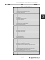
xxvi
◆◆◆ PRECAUTIONS BEFORE OPERATION ◆◆◆ .............................................. i
◆◆◆ FIRST-AID TREATMENTS ◆◆◆ .................................................................. ii
PREFACE ................................................................................................................... v
The Mounting Point of the Warning Label ................................................................ xiv
EQUIPMENT APPEARANCE ................................................................................. xviii
GLOSSARY ............................................................................................................. xxi
SECTION 1
GENERAL AND EQUIPMENT COMPOSITION
1.1
1.1.1
FUNCTIONS ...........................................................................................1-1
Function of This System .................................................................1-1
1.2
FEATURES .............................................................................................1-2
1.3
CONFIGURATION ..................................................................................1-4
1.4
EXTERIOR DRAWINGS .........................................................................1-5
1.5
GENERAL SYSTEM DIAGRAMS ........................................................1-14
SECTION 2
NAMES AND FUNCTIONS OF CONTROL PANEL KEYS AND FUNCTIONS OF
SOFTWARE BUTTONS
2.1
NAMES OF DISPLAY .............................................................................2-1
2.2
NAMES AND FUNCTIONS OF CONTROL PANEL KEYS ..................2-11
2.3
FUNCTIONS OF SOFTWARE BUTTONS ...........................................2-16
SECTION 3
BASIC OPERATION
3.1
OPERATION FLOW ...............................................................................3-1
3.1.1
Power ON and Start the System ....................................................3-2
3.1.2
Observe and Adjust Video ..............................................................3-4
3.1.3
Acquire and Measure Data .............................................................3-4
3.1.4
Display and Measure with Reference to CCRP ............................3-4
3.1.5
End the Operation and Stop the System .......................................3-5
3.2
OBSERVE AND ADJUST VIDEO ..........................................................3-6
3.2.1
Adjust Monitor Brilliance [BRILL] ..................................................3-6
3.2.2
Change Observation Range [RANGE+/-] ......................................3-6
3.2.3
Tune ..................................................................................................3-7
3.2.4
Adjust Gain [GAIN] .........................................................................3-8
3.2.5
Suppress Sea Clutter [SEA] ..........................................................3-9
3.2.6
Suppress Rain/Snow Clutter [RAIN] ...........................................3-11
3.2.7
Reset Alarm Buzzer [ALARM ACK] .............................................3-13
3.2.8
To get the appropriate image that targets can be easily observed .
3-14
3.3
OPERATION PROCEDURES ..............................................................3-15
3.3.1
Move Cross Cursor Mark by Trackball ........................................3-15
3.3.2
Operate Software Buttons ...........................................................3-16
3.3.3
Basic Menu Operation ..................................................................3-17
3.3.4
Operation on Numeric Value, Latitude / Longitude and Character
Input menu .....................................................................................3-18
3.3.5
3.4
Overview of Menu Structure .........................................................3-23
GENERAL RADAR OPERATION ........................................................3-24
3.4.1
Interference Rejection (IR) ............................................................3-24
3.4.2
Switch Transmitter Pulse Length [GAIN] ....................................3-25
3.4.3
Target Enhance (ENH) ..................................................................3-26
3.4.4
Use Video Processing (PROC) .....................................................3-27
3.4.5
Switch Azimuth Display Mode (AZI MODE) ................................3-28
3.4.6
Switch True/Relative Motion Display Mode (TM/RM) .................3-29
3.4.7
Move Own Ship’s Display Position (Off Center) .........................3-30
3.4.8
Display Radar Trails (Trails) .........................................................3-31
3.4.9
Zoom (x2) .......................................................................................3-34
3.4.10
Hide/Display Range Rings [HL OFF] ...........................................3-35
3.4.11
Hide Graphics Information on Radar Display [DATA OFF] .......3-35
3.4.12
Switch Day/Night Mode [DAY/NIGHT] .........................................3-36
3.4.13
Adjust Operation Panel Brilliance [PANEL] ................................3-36
3.4.14
Set True Bearing ............................................................................3-37
3.4.15
Set Own Ship Speed .....................................................................3-37
3.4.16
Magnet Compass Correction (MAG Compass Setting) .............3-38
3.5
USE OWN SHIP'S TRACK ...................................................................3-40
3.5.1
Display Own Ship's Track (Display Own Track) .........................3-40
3.5.2
Set Display Color of Own Ship's Track (Display Own Track Color) .3-41
3.5.3
Save Own Ship's Track (Own Track Memory) ............................3-42
3.5.4
Cancel Saving of Own Ship's Track (Own Track Memory) ........3-42
3.5.5
Clear Own Ship's Track (Clear Own Track) ................................3-43
3.5.6
Use Expanded Own Ship's Track (Own Track Type) .................3-43
3.5.7
Use Water Depth Track (Water Depth Track) ..............................3-45
3.5.8
Use Water Temperature Track (Water TEMP Track) ..................3-46
3.5.9
3.6
Use Tidal Current Track (Current Vector Track) .........................3-47
DISPLAY USER MAP ...........................................................................3-48
3.6.1
Create User Map (Mark/Line) ........................................................3-48
3.6.2
Set User Map Display (Mark Display Setting) .............................3-51
3.6.3
Edit User Map (Edit User Map) .....................................................3-53
3.6.4
Correct Position on User Map (Shift User Map) .........................3-61
3.6.5
Save User Map ...............................................................................3-62
3.6.6
Set and Display Geodetic System (Geodetic) .............................3-66
3.7
USE ROUTE FUNCTION ......................................................................3-68
3.7.1
Display Route/Destination Mark (Select Route) .........................3-68
3.7.2
Edit Route (Set Route Sequence) ................................................3-69
3.7.3
Edit Route Make with Latitude and Longitude (Waypoint Input) 3-76
3.7.4
Use Route Monitoring Function (Waypoint/Route Alarm) .........3-80
3.7.5
Method of Using Route .................................................................3-82
3.7.6
Detailed Route Settings ................................................................3-83
3.7.7
Clear Waypoint/Route Data (Clear WPT/Route Data) .................3-88
3.7.8
Operate Route Data File ................................................................3-89
3.8
APPLIED OPERATIONS ......................................................................3-93
3.8.1
Set Radar Signal Processing (Process Setting) .........................3-93
3.8.2
Set Radar Trails (RADAR Trails Setting) .....................................3-97
3.8.3
Set Scanner Unit (TXRX Setting) .................................................3-99
3.8.4
Set Cursor (Cursor Setting) ........................................................3-100
3.8.5
Set Radar Display (Display Setting) ..........................................3-101
3.8.6
Adjust Sound Volume (Buzzer Volume) ....................................3-104
3.8.7
Set User Option Keys [OPTION 1/2] ..........................................3-104
3.8.8
Set Navigation Data Display (Multi Window Setting) ...............3-106
3.8.9
AUTO Backup ..............................................................................3-111
3.9
USE FUNCTION KEY [USER] ...........................................................3-113
3.9.1
Operation Procedures .................................................................3-113
3.9.2
Function Setting Menu Items .....................................................3-114
3.9.3
Overview of Function Operations (User Function Setting) .....3-115
3.9.4
Overview of saved Function Setting Data .................................3-119
3.10
USE USER SETTING .........................................................................3-120
3.10.1
Save Operating State (Save User Setting) ................................3-120
3.10.2
Load Operating State (Load User Setting) ................................3-121
3.10.3
3.11
USING CARD .....................................................................................3-122
3.11.1
3.12
Delete Operating State (Delete User Setting) ...........................3-121
Operate File on the Card (File Manager) ...................................3-122
RECEIVE PORT SETTING .................................................................3-129
3.12.1
Receive Port Setting (RX Port) ...................................................3-129
SECTION 4
MEASUREMENT OF RANGE AND BEARING
4.1
USE OF NAVIGATION TOOLS ..............................................................4-1
4.1.1
Using Cursor (Cursor) ....................................................................4-2
4.1.2
Using Range Rings (Range Rings) ................................................4-2
4.1.3
Using Electronic Bearing Line (EBL1/EBL2) ................................4-3
4.1.4
Using Parallel Index Lines (PI Menu) .............................................4-8
4.1.5
Operating EBL Maneuver Function (EBL Maneuver Setting) ....4-14
4.1.6
Operating EBL, VRM, and PI with Cursor ...................................4-16
4.2
MEASUREMENT OF RANGE AND BEARING ....................................4-19
4.2.1
Measurement with Cursor Position (Cursor) ..............................4-20
4.2.2
Measurement with Electronic Bearing Line and Variable Range
Marker [EBL] [VRM] .....................................................................4-20
4.2.3
Measurement with Two Arbitrary Points .....................................4-21
SECTION 5
OPERATION OF TARGET TRACKING AND AIS
5.1
PREPARATION ......................................................................................5-1
5.1.1
Collision Avoidance ........................................................................5-2
5.1.2
Definitions of Symbols ...................................................................5-5
5.1.3
Radar Display ..................................................................................5-9
5.1.4
Cursor Modes (Cursor) .................................................................5-11
5.1.5
Setting Collision Decision Criteria ..............................................5-13
5.1.6
Setting Vectors (Vector Time) ......................................................5-14
5.1.7
Setting the GPS antenna location ................................................5-14
5.2
TARGET TRACKING OPERATION .....................................................5-15
5.2.1
Acquiring Target [ACQ] ................................................................5-15
5.2.2
Canceling Unwanted Tracked Targets [ACQ CANCEL] .............5-17
5.2.3
Tracked Target Data Display [TGT DATA] ..................................5-18
5.2.4
Displaying Target ID No.(Target Number Display) .....................5-19
5.2.5
Adding Tracked Target ID Name (Name) .....................................5-20
5.2.6
Reference Target (Reference) ......................................................5-21
5.2.7
Operation Test (TT Test Menu) ...................................................5-22
5.3
AIS OPERATION ..................................................................................5-27
5.3.1
Restrictions ....................................................................................5-27
5.3.2
Setting AIS Display Function (AIS Function) ..............................5-27
5.3.3
Activate AIS Targets (Activate AIS) .............................................5-28
5.3.4
Deactivate AIS Targets (Deactivate AIS) .....................................5-28
5.3.5
Displaying AIS Information [TGT DATA] .....................................5-29
5.3.6
Displaying Target ID No. (Target Number Display) ....................5-32
5.3.7
Setting AIS Filter (AIS Filter Setting) ...........................................5-33
5.3.8
Conditions for Deciding AIS Target to be Lost ..........................5-36
5.3.9
Setting Conditions for AIS Alarm (AIS Alarm Setting) ...............5-37
5.4
DECISION OF TARGETS AS IDENTICAL (Association) ...................5-38
5.4.1
Setting of Function to Decide Targets as Identical (Association) 5-38
5.4.2
Setting of Conditions for Deciding AIS and Tracked Targets as
Identical (Association Setting) .....................................................5-38
5.4.3
5.5
Types of Decision Conditions to be Set ......................................5-39
ALARM DISPLAY .................................................................................5-40
5.5.1
CPA / TCPA Alarm .........................................................................5-41
5.5.2
Alarm for New Target Acquired in Automatic Acquisition Zone
(New Target) ...................................................................................5-42
5.5.3
Lost Target Alarm (Lost) ...............................................................5-42
5.5.4
Gyro Set Alarm ..............................................................................5-43
5.6
TRACK FUNCTION ..............................................................................5-44
5.6.1
Past Position (Past POSN) ...........................................................5-44
5.6.2
Target Ship's Tracks (Target Track) ............................................5-45
5.7
TRIAL MANEUVERING
(Trial Maneuver) ..........................5-54
5.7.1
Trial Maneuvering in the True Vector Mode ................................5-55
5.7.2
Trial Maneuvering in the Relative Vector Mode ..........................5-56
5.7.3
Operation of Trial Maneuvering Function ...................................5-57
SECTION 6
TRUE AND FALSE ECHOES ON DISPLAY
6.1
RADAR WAVE WITH THE HORIZON ...................................................6-1
6.2
STRENGTH OF REFLECTION FROM THE TARGET ...........................6-3
6.3
SEA CLUTTER AND RAIN AND SNOW CLUTTER ..............................6-5
6.4
FALSE ECHOES ....................................................................................6-9
6.5
DISPLAY OF AIS-SART .......................................................................6-12
6.5.1
Display ...........................................................................................6-12
6.5.2
Numeric Display ............................................................................6-13
SECTION 7
SETTINGS FOR SYSTEM OPERATION
7.1
SETTINGS AT INSTALLATION .............................................................7-1
7.1.1
How to Open the Serviceman Menu(Service Man Menu).........7-1
7.1.2
GYRO I/F Setting .............................................................................7-2
7.1.3
Tuning (Tune Adjustment) .............................................................7-5
7.1.4
Bearing Adjustment ........................................................................7-5
7.1.5
Range Adjustment ...........................................................................7-5
7.1.6
Navigator Setting (Device) .............................................................7-6
7.1.7
Setting of True Bearing Value ........................................................7-7
7.1.8
Antenna Height Setting (Antenna Height) .....................................7-7
7.1.9
Setting of CCRP (CCRP Setting) ....................................................7-8
7.2
SETTINGS ............................................................................................7-11
7.2.1
Communication Port Setting (COM Port Setting) .......................7-11
7.2.2
Sector Blank Setting (Sector Blank) ............................................7-15
7.2.3
Setting of Bearing Pulses from Scanner Unit (Output Pulse) ...7-16
7.2.4
Slave Mode Setting (Master/Slave) ..............................................7-16
7.2.5
Language Setting (Language) ......................................................7-17
7.2.6
Date Time Setting ..........................................................................7-18
7.2.7
Input Installation Information .......................................................7-19
7.2.8
Setting the Alarm System .............................................................7-19
7.2.9
Network Setting (Network) ...........................................................7-24
7.2.10
LAN Port Setting) ..........................................................................7-27
7.3
ADJUSTMENT ......................................................................................7-30
7.3.1
Noise Level Adjustment (Noise Level) ........................................7-30
7.3.2
Adjustment of Target Tracking Function (TT) ............................7-31
7.3.3
Main Bang Suppression Level Adjustment (MBS) .....................7-33
7.3.4
Adjustment of Performance Monitor (SSR MON) .......................7-35
7.4
7.4.1
MAINTENANCE MENU ........................................................................7-38
Antenna Safety Switch (Safety Switch) .......................................7-38
7.4.2
Initialization of Memory Area(Area Initial) ...................................7-39
7.4.3
Save of Internal Memory Data (Card1/2) .....................................7-40
7.4.4
Restoration of Scanner Unit Operation Time (TXRX Time) ......7-41
7.4.5
Update of Character String Data (String Data Update) .............7-43
SECTION 8
COUNTERMEASURES FOR TROUBLE AND ADJUSTMENT
8.1
ROUTINE MAINTENANCE ....................................................................8-1
8.2
MAINTENANCE ON EACH UNIT ...........................................................8-2
8.2.1
Scanner Unit NKE-1532 .................................................................8-2
8.2.2
Display Unit (NCD-9170) ................................................................8-4
8.3
PERFORMANCE CHECK ......................................................................8-5
8.3.1
8.4
Check Performance on Test Menu ...............................................8-5
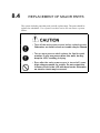
REPLACEMENT OF MAJOR PARTS ..................................................8-11
8.4.1
Parts Required for Periodic Replacement ..................................8-12
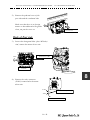
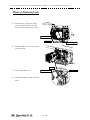
8.4.2
Replacement of Motor ...................................................................8-12
8.4.3
Replacement of 23inch LCD ........................................................8-17
8.4.4
Replacement of Backup Battery ..................................................8-20
SECTION 9
TROUBLE SHOOTING AND AFTER-SALES SERVICE
9.1
FAULT FINDING .....................................................................................9-1
9.1.1
List of Alarms and other Indications .............................................9-1
9.1.2
Operation Checking ........................................................................9-6
9.1.3
Fuse Checking .................................................................................9-6
9.2
TROUBLE SHOOTING ...........................................................................9-7
9.2.1
9.3
Circuit Block to be Repaired ..........................................................9-7
AFTER-SALES SERVICE ......................................................................9-9
9.3.1
Keeping period of maintenance parts ...........................................9-9
9.3.2
When you Request for Repair ........................................................9-9
9.3.3
Recommended Maintenance ..........................................................9-9
SECTION 10
DISPOSAL
10.1
DISPOSAL OF THE UNIT ....................................................................10-1
10.2
DISPOSAL OF USED BATTERIES .....................................................10-1
10.3
ABOUT THE CHINA ROHS .................................................................10-2
SECTION 11
SPECIFICATION
11.1
JMA-9172-SA TYPE RADAR ............................................................... 11-1
11.2
SCANNER UNIT (NKE-1532) ...............................................................11-2
11.3
DISPLAY UNIT (NCD-9170) .................................................................11-3
11.4
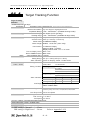
Target Tracking Function ...................................................................11-6
11.5
AIS FUNCTION .....................................................................................11-7
Appendix A
NQE-3141 Interswitch Unit
A.1
OVERVIEW ............................................................................................ A-1
A.1.1
Overview ......................................................................................... A-1
A.1.2
Interswitch Setup ........................................................................... A-1
A.2
INTERSWITCH OPERATION ................................................................ A-3
A.2.1
Operation Flow ............................................................................... A-3
A.2.2
Inter Switch Menu ........................................................................... A-4
A.2.3
Change of Connection Pattern (with 2 Display Units) ................ A-6
A.2.4
Change of Connection Pattern (with 3 or More Display Units) .. A-7
A.2.5
Operating Connection Pattern Files (File Operations) ............... A-8
A.2.6
Names of Display Units and Scanner Units ................................. A-9
A.3
REFERENCE ....................................................................................... A-10
A.3.1
Preheat Time after Change of Connection Pattern ................... A-10
A.3.2
Notes on Changing Connection Pattern .................................... A-10
A.3.3
Notes on Connecting Slave Display Unit ................................... A-10
A.3.4
Setting at Installation ................................................................... A-11
Appendix B
DRAWINGS
B.1
Interconnection Diagram of Display Unit ........................................... B-1
B.1.1
NCD-9170 ........................................................................................ B-2
B.1.2
NCD-9170T ...................................................................................... B-3
B.1.3
NWZ-178-R ...................................................................................... B-4
B.1.4
NWZ-178-RT .................................................................................... B-5
B.1.5
NCE-5322-R ..................................................................................... B-6
B.1.6
NCE-5322-RT ................................................................................... B-7
B.2
Power System Diagram of Display Unit ............................................. B-8
B.3
Signal Flow Diagram of Display Unit .................................................. B-9
B.4
Primary Power System Diagram ....................................................... B-10
B.5
Block Diagram of Scanner Unit ........................................................ B-11
B.5.1
B.6
NKE-1532 ...................................................................................... B-12
Interconnection Diagram of Scanner Unit ....................................... B-13
B.6.1
NKE-1532 (AC110V) ...................................................................... B-14
B.6.2
NKE-1532 (AC220V) ...................................................................... B-15
B.7
Terminal Board Connection Diagram ............................................... B-16
B.7.1
JMA-9172-SA ................................................................................ B-17
B.7.2
NCD-9170T .................................................................................... B-18
B.8
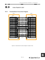
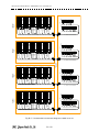
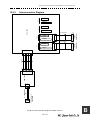
GYRO I/F ............................................................................................. B-19
B.9
Inter Switch Unit ................................................................................. B-21
B.9.1
Terminal Board Connection Diagram ......................................... B-21
B.9.2
Interconnection Diagram ............................................................. B-23
Appendix C
Menu Index
C.1
Main ....................................................................................................... C-1
C.2
PI ............................................................................................................ C-5
C.3
TT ........................................................................................................... C-7
C.4
AIS ......................................................................................................... C-8
C.5
AZ .......................................................................................................... C-9
C.6
Track .................................................................................................... C-10
C.7
Route ................................................................................................... C-11
C.8
U.Map .................................................................................................. C-12
C.9
Serviceman Menu ............................................................................... C-14
Modified April 15, 2011 15:46
1
GENERAL AND EQUIPMENT COMPOSITION
1
2
NAMES AND FUNCTIONS OF CONTROL PANEL
KEYS AND FUNCTIONS OF SOFTWARE BUTTONS
2
3
BASIC OPERATION
3
4
MEASUREMENT OF RANGE AND BEARING
4
5
OPERATION OF TARGET TRACKING AND AIS
5
6
TRUE AND FALSE ECHOES ON DISPLAY
6
7
SETTINGS FOR SYSTEM OPERATION
7
8
COUNTERMEASURES FOR TROUBLE AND
ADJUSTMENT
8
9
TROUBLE SHOOTING AND AFTER-SALES
SERVICE
9
10
DISPOSAL
10
11
SPECIFICATIONS
11
Appendix
A
SECTION 1
GENERAL AND EQUIPMENT COMPOSITION
GENERAL AND EQUIPMENT COMPOSITION
1.1
FUNCTIONS ...........................................................................................1-1
1.1.1
Function of This System .................................................................1-1
1.2
FEATURES .............................................................................................1-2
1.3
CONFIGURATION ..................................................................................1-4
1.4
EXTERIOR DRAWINGS .........................................................................1-5
1.5
GENERAL SYSTEM DIAGRAMS ........................................................1-14
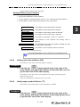
JMA-9172-SA Instruction Manual
1.1
>
1.GENERAL AND EQUIPMENT COMPOSITION
>
1.1 FUNCTIONS
FUNCTIONS
This equipment is a high-performance radar equipment consisting of a scanner
unit, a transmitter-receiver unit and a high resolution color LCD display unit.
This equipment complies with the performance standard of IMO.
1.1.1
Function of This System
The JMA-9172-SA is a color radar system designed to comply with the
international standards of the IMO.The main functions include:
•
•
•
•
•
•
•
•
•
•
•
sensitivity adjustment
sea clutter and rain/snow clutter suppression
interference rejection
bearing and range measurement using a cursor, fixed/variable range markers,
and electronic bearing line
colored own track display(7 colors)
NAV line and marker displays
TM (True Motion) presentation
self-diagnostic facilities
radar performance monitoring (Performance Monitor)
Target Tracking functions (manual/automatic, target acquisition and tracking,
vector and trail displays, Trial maneuver and alarm displays)
8-unit switchover (Interswitch) function (option)
1-1
1
JMA-9172-SA Instruction Manual > 1.GENERAL AND EQUIPMENT COMPOSITION > 1.2 FEATURES
1.2
FEATURES
Realization of Large, Easy-to-see Screen with High Resolution
The 23.1-inch color LCD1 with high resolution can display radar images of 320
mm or more in diameter. Even short-range targets can also be displayed as highresolution images.
Target Detection by Latest Signal Processing Technology
The system employs the latest digital signal processing technology to eliminate
undesired clutter from the radar video signals that are obtained from the receiver
with a wide dynamic range, thus improving the target detection.
Target Tracking (TT) Function based on Advanced Technology
The target acquisition and tracking performance is enhanced by the use of the
fastest DSP and tracking algorithm. So stable operation in target tracking under
clutter is ensured.
• Acquisition and tracking of 100 targets.
• Hazardous conditions are represented by shapes and colors of symbols as well
as sounds.
• Trial maneuvering functions provided.
• Tracks of up to 20 target ships can be stored with a maximum of 1,500 points
for each of them, and displayed distinguished by using seven different colors.
Overlay of Radar Images, Coastlines, and Own Ship's Track
As well as operator-created NAV lines and own ship's tracks/ARPA tracks, which
is stored on the memory card can be superimpose-displayed with radar images and
radar trails in all display modes including the head-up mode.
Easy Operation with GUI
All the radar functions can be easily controlled by simply using the trackball and
two switches to operate the buttons shown on the radar display.
1.The displayed resolution corresponds to SXGA(1280x1024).
1-2
JMA-9172-SA Instruction Manual > 1.GENERAL AND EQUIPMENT COMPOSITION > 1.2 FEATURES
Improved Day/Night Mode
Five types of background colors are available in Day/Dusk/Night mode (total 5
background colors). Each background color can be reproduced to be suited for the
user's operating environment by simple key operation. The radar echoes and a
variety of graphics can also be represented in different colors, ensuring easy-tosee displays.
Compact Design and Low Power Consumption
Since an LCD has been implemented as the display device, the weight of the
display is greatly reduced and the power consumption is lowered in comparison
with the conventional radar equipment.
Self-diagnostic Program Incorporated
The Self-diagnostic program always monitors all the functions of the system. If
any function deteriorates, an alarm message will appear on the radar display and
an alarm sounds at the same time. Even when the system is operating, the
functionality test can be carried out. (except on some functions)
Performance Monitor
The radar performance (transmitted output power and receiving sensitivity) can
appear on the radar display.
Easy Interswitch Operation (Option)
If an interswitch unit (option) is connected, up to eight JMA-9172-SA radar can
be switched over by performing simple operation.
Up to 2 radars:
NQE-3141-2A is needed in Display Unit.
Up to 4 radars:
NQE-3141-4A is needed separately.
Up to 8 radars:
NQE-3141-8A is needed separately.
Various Functions
•
•
•
•
•
RADAR Trails (Other ship's track display)
TM (True Motion) display
Head-up/North-up/Course-up display
Own ship's track display
Auto-acquisition Zone function
1-3
1
JMA-9172-SA Instruction Manual > 1.GENERAL AND EQUIPMENT COMPOSITION > 1.3 CONFIGURATION
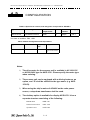
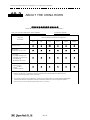
1.3
CONFIGURATION
Table1-1:Specified of scanner, and categories of ship/craft for SOLAS V
Type of Radar
Antenna type
Transmitted
Output Power
Band
Rate of
rotation
JMA-9172-SA
12ft Slotted Antenna
250W
S
24rpm
Category
CAT 1
The class of emission: P0N , Q0N
Table1-2:Radar Configuration and Ship's Mains
Type of Radar
Scanner Unit
Display
Unit
Ship’s Main
JMA-9172-SA
NKE-1532
NCD-9170
AC100 to 115V, or
AC220 to 240V 50/60Hz
1φ
Notes:
1)
The drive motor for the scanner unit is available in AC100-115V
or AC220-240V type for NKE-1532 . Please specify the motor type
when ordering.
2)
The scanner unit can be equipped with a deicing heater as an
option, and '-D' shall be suffixed to the type name. (e.g. NKE1532-D).
3)
When using the ship's mains of AC440V as the radar power
source, a step-down transformer shall be used.
4)
The desktop option is available for display NCD-9170. It has a
separate structure consisting of the following:
Monitor Unit
NWZ-178
Radar Process Unit
NDC-1478
Operation Unit
NCE-5322
1-4
JMA-9172-SA Instruction Manual
1.4
>
1.GENERAL AND EQUIPMENT COMPOSITION
>
1.4 EXTERIOR DRAWINGS
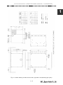
EXTERIOR DRAWINGS
Fig 1-1: Outline Drawing of Scanner Unit, Type NKE-1532
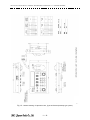
Fig 1-2: Outline Drawing of Display Unit, Type NCD-9170
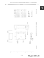
Fig 1-3: Outline Drawing of Monitor Unit, Type NWZ-178 (Desktop type option)
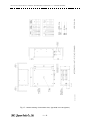
Fig 1-4: Outline Drawing of Radar Process Unit, Type NDC-1478 (Desktop type option)
Fig 1-5: Outline Drawing of Operation Unit, Type NCE-5322 (Desktop type option)
Fig 1-6: Outline Drawing of Interswitch Unit, Type NQE-3141-4A (Option)
Fig 1-7: Outline Drawing of Interswitch Unit, Type NQE-3141-8A (Option)
Fig 1-8: Outline Drawing of Power Control Unit, Type NQE-3167 (Option)
1-5
1
JMA-9172-SA Instruction Manual > 1.GENERAL AND EQUIPMENT COMPOSITION > 1.4 EXTERIOR DRAWINGS
Fig 1-1: Outline Drawing of Scanner Unit, Type NKE-1532
1-6
JMA-9172-SA Instruction Manual > 1.GENERAL AND EQUIPMENT COMPOSITION > 1.4 EXTERIOR DRAWINGS
1
Fig 1-2: Outline Drawing of Display Unit, Type NCD-9170
1-7
JMA-9172-SA Instruction Manual > 1.GENERAL AND EQUIPMENT COMPOSITION > 1.4 EXTERIOR DRAWINGS
Fig 1-3: Outline Drawing of Monitor Unit, Type NWZ-178 (Desktop type option)
1-8
JMA-9172-SA Instruction Manual > 1.GENERAL AND EQUIPMENT COMPOSITION > 1.4 EXTERIOR DRAWINGS
1
Fig 1-4: Outline Drawing of Radar Process Unit, Type NDC-1478 (Desktop type option)
1-9
JMA-9172-SA Instruction Manual > 1.GENERAL AND EQUIPMENT COMPOSITION > 1.4 EXTERIOR DRAWINGS
Fig 1-5: Outline Drawing of Operation Unit, Type NCE-5322 (Desktop type option)
1 - 10
JMA-9172-SA Instruction Manual > 1.GENERAL AND EQUIPMENT COMPOSITION > 1.4 EXTERIOR DRAWINGS
1
Fig 1-6: Outline Drawing of Interswitch Unit, Type NQE-3141-4A (Option)
1 - 11
JMA-9172-SA Instruction Manual > 1.GENERAL AND EQUIPMENT COMPOSITION > 1.4 EXTERIOR DRAWINGS
Fig 1-7: Outline Drawing of Interswitch Unit, Type NQE-3141-8A (Option)
1 - 12
JMA-9172-SA Instruction Manual > 1.GENERAL AND EQUIPMENT COMPOSITION > 1.4 EXTERIOR DRAWINGS
1
Fig 1-8: Outline Drawing of Power Control Unit, Type NQE-3167 (Option)
1 - 13
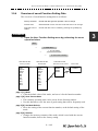
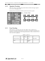
JMA-9172-SA Instruction Manual > 1.GENERAL AND EQUIPMENT COMPOSITION > 1.5 GENERAL SYSTEM DIAGRAMS
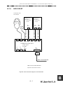
1.5
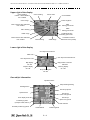
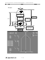
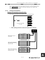
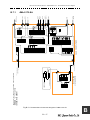
GENERAL SYSTEM DIAGRAMS
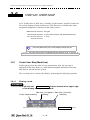
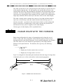
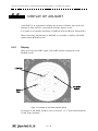
Fig 1-9: General System Diagram of Radar, Type JMA-9172-SA
1 - 14
JMA-9172-SA Instruction Manual > 1.GENERAL AND EQUIPMENT COMPOSITION > 1.5 GENERAL SYSTEM DIAGRAMS
1
NKE-1532
SCANNER UNIT
CIRCUIT BREAKER
(SHIP YARD SUPPLY)
(5A)
AC100V,60Hz
1φ,200W
0.6/1kV-DPYCYS-1.5
NBL-175
STEPDOWN
TRANSFORMER
SHIP’S MAIN
for HEATER
AC220V,60Hz,1φ
14 CORES COMPOSITE CABLE
H-2695110056
MAX 23φ (JRC SUPPLY)
NCD-9170
DISPLAY UNIT
GYRO
LOG (NMEA 0183)
DGPS
VDR
RADAR (INTER SWITCH)
0.6/1kV-DPYCY-6
250V-MPYCYS-7
SHIP’S MAIN
AC220V,60Hz,1φ,800VA
250V-TTYCS-1
0.6/1kV-DPYCYS-1.5
250V-TTYCS-1
SHIP’S MAIN
for POWER FAIL ALARM
DC24V(BATTERY),1W
3C-2V x5 (MAX 30m)
18 CORES COMPOSITE CABLE
H-2695111153
MAX 18.0φ (JRC SUPPLY)
250V-TTYCS-4
H-2695110006 (JRC SUPPLY )
ECDIS (JAN-901M)
H-2668510019 (JRC SUPPLY) SPARE
ALERM MONITORING SYSTEM
(NEAREST APPROACH)
(POWER FAIL)
CONNING DISPLAY (JAN-701-CON)
AIS
250V-MPYC-4
250V-TTYCS-4
250V-TTYCS-4
Fig 1-9: General System Diagram of Radar, Type JMA-9172-SA
Eliminating the interference on frequencies used for marine communications and navigation
due to operation of the radar. All cables of the radar are to be run away from the cables of radio
equipment.(Ex. Radiotelephone. Communications receiver and direction finder, etc. )
Especially inter-wiring cables between scanner unit and display unit of the radar should not be
run parallel with the cables of radio equipment.
1 - 15
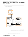
JMA-9172-SA Instruction Manual > 1.GENERAL AND EQUIPMENT COMPOSITION > 1.5 GENERAL SYSTEM DIAGRAMS
1 - 16
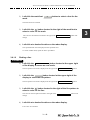
SECTION 2
NAMES AND FUNCTIONS OF CONTROL
PANEL KEYS AND FUNCTIONS OF
SOFTWARE BUTTONS
NAMES AND FUNCTIONS OF CONTROL PANEL KEYS AND FUNCTIONS OF SOFTWARE BUTTONS
2.1
2.2
2.3
NAMES OF DISPLAY .............................................................................2-1
NAMES AND FUNCTIONS OF CONTROL PANEL KEYS ..................2-11
FUNCTIONS OF SOFTWARE BUTTONS ...........................................2-16
JMA-9172-SA Instruction Manual
2.1
>
2.CONTROL PANEL KEYS and SOFTWARE BUTTONS> 2.1 NAMES OF DISPLAY
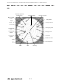
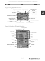
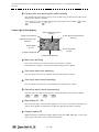
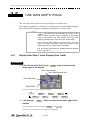
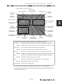
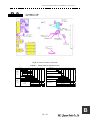
NAMES OF DISPLAY
2
Example of screen display
In this example, the screen is divided into a number of areas and the names in
each area are indicated.
Upper left
of the display
PPI
Upper right
of the display
Tuning OK
Own ship' s
information
S
Target
tracking(TT) /
AIS information
Digital information
Menu
Brilliance /
Display information
Alarm
Lower left
of the display
Lower right
of the display
2-1
JMA-9172-SA Instruction Manual
>
2.CONTROL PANEL KEYS and SOFTWARE BUTTONS
>
2.1 NAMES OF DISPLAY
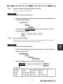
PPI
Automatic acquisition/
activation zone
Ship' s heading
marker
Ship' s
heading line
Association target
Own ship' s symbol
Tuning OK
Past position
S
AIS target number
Cursor mark
AIS target symbol
Tracked target
vector
Tracked target
number
AIS target vector
Radar trails
Tracked target
symbol
Parallel index lines
VRM2
Other ship' s track
EBL2
VRM1
EBL1
CPA ring
2-2
JMA-9172-SA Instruction Manual
>
2.CONTROL PANEL KEYS and SOFTWARE BUTTONS> 2.1 NAMES OF DISPLAY
Upper left of the display
Optimum performance indication
Range scale
Range rings display On / Off
Range rings interval
Tuning OK
Transmission pulse length
Motion mode true / relative
Radar trail true / relative
Stability mode
Off center
On / Off
Transmission / standby
Azimuth display mode
S
S band
Interswitch connection status
About ground and sea stabilization
Speed sensor source is MAN ,
LOG ,
2AXW
If Set/Drift Setting menu is on :GND (Ground stabilization)
If Set/Drift Setting menu is off :Sea (Sea stabilization)
Speed sensor source is GPS , 2AXG
:GND (Ground stabilization)
Lower left of the display
Double zoom On / Off
Interference rejection (IR) mode
Radar video processing (PROC)
mode
Target enhance (ENH) mode
Function (FUNC) mode
Sea clutter suppression (Sea)
mode
Gain dial position
Rain / snow clutter suppression
(Rain) mode
Sea clutter uppression (Sea)
dial position
Rain / snow clutter
suppression (Rain)
dial position
2-3
2
JMA-9172-SA Instruction Manual
>
2.CONTROL PANEL KEYS and SOFTWARE BUTTONS
>
2.1 NAMES OF DISPLAY
Upper right of the display
Cursor bearing
numeric value indication
true / relative
Cursor bearing
Cursor mode
Cursor latitude
Cursor range
Cursor longitude
EBL1 numeric value indication
true / relative
EBL1
starting point mode
EBL1 bearing
EBL2
starting point mode
Parallel index line
starting point mode
VRM1 range
EBL2 numeric value indication
true / relative
EBL2 bearing
Consistent Common
Reference Point (CCRP)
VRM2 range
Lower right of the display
Own ship's track interval
Mark color
Own ship's track interval unit
Own ship's track color
Map position correction
indication
Map display
On / Off
Graphic display
On / Off
CPA ring display
On / Off
Ship's heading line
On / Off
Own ship's information
Operation status
Ship's heading bearing
Heading device
Own ship's speed
Speed sensor
Own ship's
course over ground
Time display mode
Own ship's
speed over ground
Positioning system
(example: GPS, DGPS )
Date and time
Geodetic positioning system
CCRP latitude
2-4
CCRP longitude
JMA-9172-SA Instruction Manual
>
2.CONTROL PANEL KEYS and SOFTWARE BUTTONS> 2.1 NAMES OF DISPLAY
Target tracking (TT) / AIS information
Target vector true / relative
Target vector length
Past position display
interval
TCPA limit
CPA limit
Past position display
interval unit
Past position true / relative
Association On / Off
AIS On / Off
AIS filter mode
Tracked target symbol
display On / Off
AIS target symbol display
On / Off
Target tracking (TT) /
EPA / AIS
Radar trails remaining time
Radar trails true / relative
Radar trails display time
Numeric information: AIS target information
AIS target number
Simple display item
Ship's name
Unread message
Call sign
MMSI
Course
CPA
Speed
TCPA
Bearing
Ship's heading bearing
Rate of turn
Range
Latitude
Latitude / longitude error
Longitude
Navigation status
Destination
2-5
2
JMA-9172-SA Instruction Manual
>
2.CONTROL PANEL KEYS and SOFTWARE BUTTONS
>
2.1 NAMES OF DISPLAY
About time display mode
UTC : Universal Time Coordinate
UTC(S) : UTC (System Time)
LMT : Local Mean Time
LMT (S) : LMT (System Time)
Numeric information: Tracked target information
Tracked target number
Bearing
True course
Range
True speed
CPA
BCR
TCPA
BCT
No information is displayed
if digital information value is
not displayed
Numeric information: Enhancement of cursor position numeric value indication
Cursor bearing numeric
value indication
true / relative
Cursor bearing
Cursor range
Cursor latitude
Cursor longitude
2-6
JMA-9172-SA Instruction Manual
>
2.CONTROL PANEL KEYS and SOFTWARE BUTTONS> 2.1 NAMES OF DISPLAY
Numeric information: Enhancement of EBL / VRM numeric value display
EBL bearing
numeric value indication
true / relative
EBL bearing
VRM range
2
Numeric information: Navigation information
Depth
Current direction
Water temperature
Current speed
Wind direction
Wind direction / speed
numeric value indication
true / relative
Wind speed
Destination bearing
Destination distance
Remaining time before
arriving destination
Graph information: Depth indication
Depth
Depth range
Depth graph
Time range
2-7
JMA-9172-SA Instruction Manual
>
2.CONTROL PANEL KEYS and SOFTWARE BUTTONS
>
2.1 NAMES OF DISPLAY
Graph information: Water temperature indication
Water temperature
Water temperature range
Water temperature graph
Time range
Graph information: Wind direction / speed
Wind direction / speed
true / relative
Wind direction
Wind speed
Graph information: Course bar
Auto pilot course
Ship's heading bearing
Rudder
Rate of turn
2-8
JMA-9172-SA Instruction Manual
>
2.CONTROL PANEL KEYS and SOFTWARE BUTTONS> 2.1 NAMES OF DISPLAY
Numeric information: Marker
Marker bearing
Marker latitude
Marker range
Marker longitude
Arrival time
Menu
Main menu
Digital information
Parallel index line menu
Automatic acquisition /
activation zone (AZ) menu
Target Tracking (TT) menu
Own Track menu
User map menu
AIS menu
Route menu
Brilliance
Main menu
Digital information
Parallel index line menu
Automatic acquisition /
activation zone (AZ) menu
Target Tracking (TT) menu
Own Track menu
User map menu
AIS menu
Route menu
Display information
Panel lighting brilliance
Radar video brilliance
Day / night mode
Tracked target / AIS target
symbol brilliance
2-9
2
JMA-9172-SA Instruction Manual
>
2.CONTROL PANEL KEYS and SOFTWARE BUTTONS
>
2.1 NAMES OF DISPLAY
Alarm
Alarm indication
(The system alarm indicated in red .
Other information indicated in blue or yellow.)
2 - 10
JMA-9172-SA Instruction Manual
2.CONTROL PANEL KEYS and SOFTWARE BUTTONS> 2.2 NAMES AND FUNCTIONS OF
CONTROL PANEL KEYS
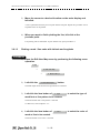
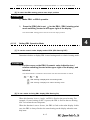
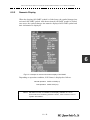
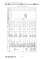
NAMES AND FUNCTIONS OF
CONTROL PANEL KEYS
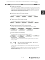
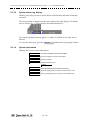
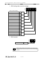
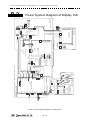
13
VRM1
2
1
27
OPTION
OPTION
25
USER
PANEL
EBL2
EBL1
POWER
24
12
11
ALARM
ACK
TX
STBY
10
4
3
PWR FAIL
PWR
ACK
2
20
5
TUNE
21
AIS/AR
PA
DAY
NIGHT
26
22
DATA
OFF
CANCEL
MANUAL
HL
OFF
ACQ
ACQ
TGT
DATA
T/R
VECT
RAIN
17
6
16
18
7
SEA
19
23
8
GAIN
15
VRM2
14
9
RANGE
29
28
30
2
1
2.2
>
The name of each button is described from the following page. See below.
2 - 11
JMA-9172-SA Instruction Manual
CONTROL PANEL KEYS
1
>
2.CONTROL PANEL KEYS and SOFTWARE BUTTONS
>
2.2 NAMES AND FUNCTIONS OF
[POWER] (Power supply) switch
The lamp is lit and the equipment is activated.
If this switch is pressed while the equipment is running, the power of the equipment is
shut down.
→ 3.1.1 on page 3-2
2
[PWR ACK] (Power alarm acknowledgement) key
Use this function to acknowledge the alarm when power supply abnormality occurs.
To enable this key, an external battery (separate power from normal AC) is required.
3
[TX/STBY] (Transmission/Standby) key
When the [POWER] switch is pressed, the "STANDBY" message is displayed in the
top-left corner of the screen in about 10 seconds. If this key is pressed, transmission
starts. If this key is pressed during transmission, the equipment is set to a standby state.
→ 3.1.1 on page 3-2
4
[ALARM ACK] (Alarm acknowledgement) key
Use this function to acknowledge alarms such as failure alarm, approaching target alarm,
and collision alarm.
By pressing this key at the occurrence of an alarm, the alarm sound can be stopped.
If multiple alarms occur, press this key same time as the alarms.
→ 3.2.7 on page 3-13
5
[TUNE] (Tuning) dial
Not function.
JMA-9172-SA radar is fully automatic. There is no necessary for a tuning function.
6
[RAIN] (Rain / snow clutter suppression) dial
This function suppresses rain / snow clutters.
To increase the effect of suppression, turn the dial clockwise.
The mode can be switched to manual or automatic by pressing the dial.
→ 3.2.6 on page 3-11
7
[SEA] (Sea clutter suppression) dial
This function suppresses sea clutter.
To increase the effect of suppression, turn the dial clockwise.
The mode can be switched to manual or automatic by pressing the dial.
→ 3.2.5 on page 3-9
2 - 12
JMA-9172-SA Instruction Manual
8
>
2.CONTROL PANEL KEYS and SOFTWARE BUTTONS> 2.2 NAMES AND FUNCTIONS OF
CONTROL PANEL KEYS
[GAIN] (Gain/pulse length) dial
This function adjusts the reception sensitivity of the radar.
To increase the sensitivity, turn the dial clockwise.
The transmission pulse width can be switched by pressing the dial.
gain→ 3.2.4 on page 3-8
pulse width →3.4.2 on page 3-25
9
[RANGE +/-] (Range switching) key
This function switches the range.
Press [+] to increase the observation range.
Press [-] to reduce the observation range.
→ 3.2.2 on page 3-6
10
[EBL1] (Electronic Bearing Line 1) key
Use this function to display and select EBL1.
If the key is pressed for 2 seconds or more, the menu for setting EBL1 is displayed.
→ 4.1.3 on page 4-3
11
[EBL2] (Electronic Bearing Line 2) key
Use this function to display and select EBL2.
If the key is pressed for 2 seconds or more, the menu for setting EBL2 is displayed.
→ 4.1.3 on page 4-3
12
[EBL] (Electronic Bearing Line) dial
This function rotates the azimuth of the EBL that is selected in EBL1/2.
By pressing the dial, the selected EBL can be switched to Center fixing → Floating →
Center fixing.
→ 4.1.3 on page 4-3
13
[VRM1] (Variable Range Marker 1) key
This function selects VRM1. The On/Off and dial use right are switched.
→ on page 4-6
14
[VRM2] (Variable Range Marker 2) key
This function selects VRM2. The On/Off and dial use right are switched.
→ on page 4-6
2 - 13
2
JMA-9172-SA Instruction Manual
CONTROL PANEL KEYS
15
>
2.CONTROL PANEL KEYS and SOFTWARE BUTTONS
>
2.2 NAMES AND FUNCTIONS OF
[VRM] (Variable Range Marker) dial
This function changes the range of the VRM that is selected by VRM1/2.
By pressing the dial, the parallel line cursor function can be switched to Operation →
Fixed → Off → Operation.
→ on page 4-6
16
[T/R VECT] (True vector display / Relative vector display) key
This function switches the display mode (true/relative) of the tracked target and AIS
target vector.
→ 5.1.6 on page 5-14
17
[TGT DATA] (Target data display) key
This function displays the digital data of the tracked target or AIS target at the cursor
position.
the tracked target →5.2.3 on page 5-18
the AIS target →5.3.5 on page 5-29
18
[ACQ MANUAL] (Manual acquisition) key
This function enables manual acquisition of the target at the cursor position.
→ 5.2.1 on page 5-15
19
[ACQ CANCEL] (Tracked target cancellation) key
This function cancels the symbol and vector of the target that is being tracked and stops
the tracking of the target.
If this key is pressed for 2 seconds or more, all the targets that are being tracked are
cancelled.
→ 5.2.2 on page 5-17
20
[DAY /NIGHT] (Day/night mode) key
This function switches the color and brightness of the screen that was preset.
→ 3.4.12 on page 3-36
21
[AIS/TT] (AIS On/Off) key
This function switches the AIS function to ON/OFF when the AIS function is enabled.
→ 5.3.2 on page 5-27
22
[HL OFF] (Ship's heading line Off) key
HL (ship's heading highlight line) can be set to Off only while this key is pressed.
→ 3.4.10 on page 3-35
2 - 14
JMA-9172-SA Instruction Manual
23
>
2.CONTROL PANEL KEYS and SOFTWARE BUTTONS> 2.2 NAMES AND FUNCTIONS OF
CONTROL PANEL KEYS
[DATA OFF] (DATA Off) key
This function sets the graphics other than HL, range ring, EBL, and VRM to OFF
temporarily while this key is pressed.
→ 3.4.11 on page 3-35
24
[PANEL] (Operator panel brilliance) key
This function adjusts the lighting brilliance of various switches and dial positions on the
operator panel. The brightness changes cyclically whenever this key is pressed.
→ 3.4.13 on page 3-36
25
[USER] key
By pressing this key, the signal processing setting that is preset can be called.
The setting changes to FUNC OFF ==> FUNC1 ==> FUNC2 ==> FUNC3 ==>
FUNC4 whenever this key is pressed.
If this key pressed for 2 seconds or more, the function setting menu is displayed.
→ 3.9 on page 3-113
26
[OPTION1] key
By pressing this key, the pre-registered menu position can be directly displayed.
At factory shipment, the calling of [Main Menu] is assigned.
→ 3.8.7 on page 3-104
27
[OPTION2] key
By pressing this key, the pre-registered menu position can be directly displayed.
At factory shipment, the calling of [Sub Menu] is assigned.
→ 3.8.7 on page 3-104
28
Track ball
This function moves the cursor mark to any position. Use this function for setting in
each mode.
Use this function to specify a center position of floating EBL and an off-center position.
→ 3.3.1 on page 3-15
29
[Track ball left button]
Use this function to confirm menu selection and numeric value input.
30
[Track ball right button]
Use this function to reset menu selection and numeric value input.
31
[BRILL] (Brilliance dial)
This dial is provided at the right of the monitor. Use this function to adjust the brilliance
of the monitor.
→ 3.2.1 on page 3-6
2 - 15
2
JMA-9172-SA Instruction Manual
BUTTONS
2.3
>
2.CONTROL PANEL KEYS and SOFTWARE BUTTONS> 2.3 FUNCTIONS OF SOFTWARE
FUNCTIONS OF SOFTWARE
BUTTONS
In this radar, the frequently used functions can be directly set from the screen
without opening the menu by using the software buttons on the screen for quick
handling. The screen is divided into a number of areas and each area is named.
Upper left
of the display
PPI
Upper right
of the display
Tuning OK
Own ship' s
information
S
Target
tracking(TT) /
AIS information
Digital information
Menu
Brilliance /
Display information
Alarm
Lower left
of the display
Lower right
of the display
The name of each button is described from the next page. The function can be
used by left-clicking while setting the arrow cursor on the button position.
2 - 16
JMA-9172-SA Instruction Manual
>
2.CONTROL PANEL KEYS and SOFTWARE BUTTONS> 2.3 FUNCTIONS OF SOFTWARE
BUTTONS
Upper left of the display
① Range scale sw itching
② Range rings display
On /Off
⑦ Transmission pulse lengt
sw itching
Tuning OK
③ Motion mode true / relative
sw itching
④ Off center switching
⑤ Transmission / Standby
switching
S
⑧ Azimuth display mode
switching
⑥ Interswitch connect ion
change
1
Range scale switching
To increase the observation range scale (maximum 96NM), click
the range (minimum 0.125NM), click - .
2
+
and to reduce
Range rings display On / Off
The display of range rings are set to On / Off whenever this button is clicked.
When the display is set to On, the interval of the fixed range marker is displayed.
3
Motion mode true / relative switching
The screen motion mode is switched whenever the button is clicked.
TM
(true motion) ⇒ RM (relative motion) ⇒ TM
RM(R) indicates that the radar trails is a relative trail.
RM(T)
4
indicates that the radar trails is a true trail.
Off center switching
If this button is clicked, the cursor is moved, and left-clicked, the ship's position can be
moved to the cursor position. The moving range is within 66% of the radius.
If the button is clicked for 2 seconds, the off-center is set to Off and the ship's position is
returned to the center of the screen.
5
Transmission / standby switching
At expiration of the pre-heat time after the power is turned on,
.
Standby
Standby
Preheat
changes to
:Indicates a standby state. If this button is clicked in this state, the
equipment is set to a transmission state.
2 - 17
2
JMA-9172-SA Instruction Manual
BUTTONS
>
2.CONTROL PANEL KEYS and SOFTWARE BUTTONS
Transmit
6
>
2.3 FUNCTIONS OF SOFTWARE
:Indicates a transmission state. If this button is clicked in this state,
the equipment is set to a standby state.
Interswitch connection change
This button is displayed when the interswitch is connected. This button indicates the
connection status of the scanner unit that is connected to the indicator.
If the button is clicked in the transmission standby state, the menu for changing the
connection state between the scanner unit and the indicator is displayed. The connection
state of the scanner unit and indicator cannot be changed unless the master indicator is in
a standby state.
Refer to the Appendix A NQE-3141 Interswitch Unit Interswitch (Optional) Instruction
Manual that is attached for the setting method. This button is not displayed if the
interswitch is not connected.Un-available for evaluation model.
7
Transmission pulse length switching
The transmission pulse length is switched whenever this button is clicked. Three types
of pulses are available, short pulse (SP), middle pulse (MP), and long pulse (LP). The
pulse length and repetition frequency vary even for the same short pulse, according to
the range that is used and it is displayed as SP1 , SP2 .
8
Azimuth display mode switching
The azimuth display is switched whenever this button is clicked.
H Up
(Head Up) ⇒
N Up
(North Up) ⇒
C Up
(Course Up) ⇒ H Up
If the button is clicked for 2 seconds, the GYTO Setting menu is displayed.
Lower left of the display
① Double zoom switching
② Interference rejection (IR)
mode switching
④ Radar video processing (PROC)
mode switching
③ Target enhance (ENH)
mode switching
⑤ Function (FUNC)
mode switching
⑨ Sea clutter suppression (Sea)
mode switching
⑥ Gain adjustment
⑦ Sea clutter suppression (Sea)
adjustment
⑩ Rain and snow clutter
suppression (Rain)
mode switching
⑧ Rain / snow clutter
suppression (Rain)
adjustment
2 - 18
JMA-9172-SA Instruction Manual
>
2.CONTROL PANEL KEYS and SOFTWARE BUTTONS> 2.3 FUNCTIONS OF SOFTWARE
BUTTONS
Double zoom switching
1
Use this function to enlarge to double the size the display screen of the position specified
by the cursor. If this button is clicked, the zoom mode is set. When the cursor is moved
to the radar screen and left-clicked, the screen is enlarged to double the size so that the
middle of the cursor and the own ship's position is set to the center of the screen. This
function cannot be used when the range is 0.125NM.
Interference rejection (IR) mode switching
2
The interference rejection mode is switched whenever this button is clicked.
IR Off
⇒
IR Low
⇒
IR Meddle
⇒
IR High
IR Off
⇒
Target enhance (ENH) mode switching
3
The target enhance mode is switched whenever this button is clicked.
ENH Off
⇒
ENH Level1
⇒
ENH Level2
⇒
ENH Level3
⇒
ENH Off
Radar video processing (PROC) mode switching
4
The radar video processing mode is switched whenever this button is clicked.
PROC Off
Remain
⇒
3Scan CORREL
⇒
⇒
4Scan CORREL
⇒
Peak Hold
⇒
⇒
5Scan CORREL
⇒
Rain
PROC Off
Function (FUNC) mode switching
5
The function mode is switched whenever this button is clicked.
FUNC Off
Storm
⇒
Coast
⇒
⇒
⇒
Deep Sea
FUNC Off
If the button is clicked for 2 seconds, the function registration menu (User Function
Setting) is opened.
6
,
7
, and ⑧
Gain, Sea clutter suppression(Sea)、Rain / snow
clutter suppression (Rain)
Adjust the gain, sea clutter suppression, rain / snow clutter suppression and tune using
the track ball.
If the button is clicked on, the adjustment value is shown at the upper-right of the cursor.
Make adjustments by moving the track ball to the left and right. Determine the
adjustment by left-clicking.
2 - 19
2
JMA-9172-SA Instruction Manual
BUTTONS
10
>
2.CONTROL PANEL KEYS and SOFTWARE BUTTONS
, 11 and
12
>
2.3 FUNCTIONS OF SOFTWARE
Sea clutter suppression (Sea) mode, Rain and snow clutter
suppression (Rain) mode switching
Use these functions to switch to the manual or automatic mode of sea clutter
suppression, rain and snow clutter suppression, and tune. The bar on the left side
indicates the position of the dial.
The mode is switched to MAN (manual) / AUTO (automatic) whenever the
button is clicked. If rain and snow clutter suppression is switched to an automatic mode,
sea clutter suppression is switched to an automatic mode also.
Upper Right of the display
⑨ EBL1 numeric value indication
true / relative switching
② Mark font / line pattern
switching
① Cursor mode switching
③ Mark color / line color
switching
④ Cursor bearing
numeric value display
true / relative switching
⑪ EBL1 starting point
mode switching
⑫ EBL2 starting point
mode switching
⑤ EBL1 adjustment
⑬ Parallel index line
setting
⑥ VRM1 adjustment
⑦ EBL2 adjustment
⑧ VRM2 adjustment
⑩ EBL2 numeric value indication
true / relative switching
1
⑭ Parallel index line
starting point mode
switching
Cursor mode switching
The mode of the function that uses the cursor is switched whenever this button is
pressed.
AUTO
DEACT AIS
⇒
⇒
ACQ TT
⇒
CNCL Data
ACT AIS
⇒
⇒
□
TGT Data
⇒
⇒
-------
CNCL TT
⇒
⇒
Property
⇒
AUTO
2
Mark font / line pattern switching
This function switches a mark font / line pattern. If this button is clicked while the cursor
mode is
(mark) or - - - - - - - (line), the mark font / line pattern is
□
changed.
2 - 20
JMA-9172-SA Instruction Manual
>
2.CONTROL PANEL KEYS and SOFTWARE BUTTONS> 2.3 FUNCTIONS OF SOFTWARE
BUTTONS
Mark color / line color switching
3
This function switches a mark color / line color. If this button is clicked while the cursor
mode is
(mark) or - - - - - - - (line), the mark color / line color is
□
changed.
Cursor bearing numeric value display true / relative switching
4
The bearing numeric value display T (true bearing) /
cursor is switched whenever this button is clicked.
5
,
6
,
7
and
R
(relative bearing) of the
EBL1 / 2 and VRM1 / 2 adjustment
8
These functions set the EBL1 , VRM1 , EBL2 , and VRM2 displays to On / Off and
acquire the operation right.
If the button is clicked on, the operation right is acquired. Make adjustments by moving
the track ball to the left and right Determine the adjustment by left-clicking.
9
and
EBL1, EBL2 numeric value true / relative switching
10
The EBL1 / 2 bearing numeric value display T (true bearing) / R (relative
bearing) is switched whenever the button is clicked.
If the button is clicked for 2 seconds, the EBL / Cursor Setting menu is displayed.
11
and
EBL1 / EBL2 starting point mode switching
12
The EBL starting point is set to CCRP or any position on the radar screen whenever this
button is clicked.
_
C
⇒
D
⇒
_
_
:Center
The starting point is fixed to the CCRP position.
C
:Screen Fix
The starting point is set to the cursor position. If leftclicked subsequently, the starting position is fixed to
the cursor position.
D
:L/L Fixi
The starting point is set to the cursor position. If
left-clicked subsequently, the starting position is
fixed to the latitude / longitude of the cursor.
(Connection of a navigator is necessary.) If the
starting point is moved outside of the screen, the
operation is reset automatically and the starting
point returns to the CCRP position.
i.
13
⇒
D
is enabled only when a navigator is connected.
Parallel index line setting
This function sets the parallel index line display to On / Off and acquires the operation
right.
If this button is clicked, the operation right is acquired and the menu is opened. After
setting, determine the setting by left-clicking.
2 - 21
2
JMA-9172-SA Instruction Manual
BUTTONS
14
>
2.CONTROL PANEL KEYS and SOFTWARE BUTTONS
>
2.3 FUNCTIONS OF SOFTWARE
Parallel index line starting point mode switching
The parallel index line starting point is set to CCRP or any position on the radar screen
whenever this button is clicked.
In the same way as for the EBL starting point, three options are available, _ : Center,
C : Screen Fix, and D : L/L Fix.
Lower right of the display
③ Own ship's track interval
switching
① Mark color switching
④ Own ship's track interval unit
switching
② Own ship’s track color
switching
⑤ Map display
On / Off
⑧ CPA ring display
On / Off
⑥ Graphic display Off
⑦ Ship's heading line Off
1
Mark color switching
The color of the mark is switched whenever this button is clicked.
If the button is clicked for 2 seconds, the Mark Setting menu is opened.
2
Own ship's track color switching
The own ship's track color is switched whenever this button is clicked.
3
Own ship's track interval switching
The own ship's track interval is switched whenever this button is clicked.
4
Own ship's track interval unit switching
The unit of the own ship's track interval is switched whenever this button is clicked.
sec
5
⇒
min
⇒
NM
⇒
sec
Map display On / Off
The own track, target track and route display are set to On / Off whenever this button is
clicked. If the button is clicked for 2 seconds, the Map Setting menu is opened.
6
Graphic display Off
While the button is clicked, the graphic display other than VRM, EBL, HL, a cursor, and
range rings on the radar screen is cleared temporarily.
2 - 22
JMA-9172-SA Instruction Manual
7
>
2.CONTROL PANEL KEYS and SOFTWARE BUTTONS> 2.3 FUNCTIONS OF SOFTWARE
BUTTONS
Ship's heading line Off
The ship's heading line (HL) display is set to Off while this button is clicked.
Since the ship's heading line is cleared while the button is clicked, the target in the ship's
heading bearing can be clearly seen.
8
CPA ring display On / Off
The CPA ring display is switched to On / Off whenever the button is clicked.
When the target vector display mode is
On.
T (true vector), the CPA ring cannot be set to
Own ship's information
① Heading device
switching
④ Manual own ship's speed
setting
② Speed sensor
switching
③ Time display mode
switching
1
Heading device switching
The heading device is switched whenever this button is clicked.
GYRO ⇒
CMPS (Electronic compass)⇒
GYRO
When the selected heading device is not connected to the equipment, an alarm is issued.
2
Speed sensor switching
The speed sensor is switched whenever the button is clicked.
MAN (Manual) ⇒
log) ⇒
LOG (Single-axis water log) ⇒
2AXG (Dual-axis ground log) ⇒
GPS
⇒
2AXW
(Dual-axis water
MAN
When the selected speed device is not connected to the equipment, an alarm is issued.
3
Time display mode switching
The time display mode UTC
(universal time clock) /
switched whenever this button is clicked.
2 - 23
LMT
(local mean time) is
2
JMA-9172-SA Instruction Manual
BUTTONS
4
>
2.CONTROL PANEL KEYS and SOFTWARE BUTTONS
>
2.3 FUNCTIONS OF SOFTWARE
Manual own ship's speed setting
When selection of the speed sensor is set to MAN , enter the own ship's speed
manually.
If this button is clicked, the numeric value input screen is opened. After setting a value,
determine the entry by clicking ENT .
Target tracking (TT) / AIS information
① Target vector display
true / relative switching
② Target vector length setting
④ TCPA limit setting
⑥ Past position display
interval switching
③ CPA limit setting
⑤ Past position display
true / relative switching
⑦ Past position display
interval unit switching
⑧ AIS
On / Off
⑪ Association
On / Off
⑨ Tracked target symbol
display On / Off
⑩ AIS target symbol display
On / Off
1
⑫ AIS filter mode switching
⑬ Radar trails display
true / relative switching
⑭ Radar trails display time
switching
Target vector display true / relative switching
The tracked target / AIS target vector display is switched to
(relative vector) whenever this button is clicked.
T
(true vector) /
R
This setting is switched together with the past position display true / relative switching.
2
Target vector length setting
Set a vector length of the tracked target / AIS target.
If this button is clicked, the numeric value input screen is opened. After setting the
length, determine the setting by clicking ENT .
3
CPA limit setting
Set a CPA limit.
If this button is clicked, the numeric value input screen is opened. After setting the limit,
determine the setting by clicking ENT .
4
TCPA limit setting
Set a TCPA limit.
If this button is clicked, the numeric value input screen is opened. After setting the limit,
determine the setting by clicking ENT .
2 - 24
JMA-9172-SA Instruction Manual
5
>
2.CONTROL PANEL KEYS and SOFTWARE BUTTONS> 2.3 FUNCTIONS OF SOFTWARE
BUTTONS
Past position display true / relative switching
The tracked target / AIS target past position display is switched to T (true past
position) / R (relative past position) whenever the button is clicked.
This setting is switched together with the target vector display true / relative switching.
6
Past position display interval switching
The past position display interval is switched whenever the button is clicked.
7
Past position display interval unit switching
The past position display interval unit is switched whenever the button is clicked.
min
8
⇒
NM
⇒
min
AIS On / Off
The AIS display is switched to On / Off whenever the button is clicked.
9
Tracked target symbol display On / Off
The tracked target symbol display is switched to On / Off whenever the button is
clicked. Use this function to avoid confusion with the AIS symbol.
10
AIS target symbol display On / Off
The AIS target symbol display is switched to On / Off whenever the button is clicked.
Use this function to avoid confusion with the tracked target symbol.
11
Association On / Off
The tracked target / AIS target association is switched to On / Off whenever the button is
clicked.
12
AIS filter mode switching
The AIS filter is switched whenever the button is clicked.
Range
13
⇒
Sector
⇒
Zone
⇒
Range
Radar trails display true / relative switching
Radar trails are switched to T (true motion trail) / R (relative motion trail)
whenever this button is clicked.
This setting is restricted by the radar display motion mode.
In relative motion display mode (RM), switching to T / R is possible.
In true motion display mode (TM), only T can be set.
2 - 25
2
JMA-9172-SA Instruction Manual
BUTTONS
14
>
2.CONTROL PANEL KEYS and SOFTWARE BUTTONS
>
2.3 FUNCTIONS OF SOFTWARE
Radar trails display time switching
The radar trails display time is switched whenever the button is clicked.
If the time does not reach the radar trails time that was set, the remaining time is
displayed on the right-hand side.
If the button is clicked for 2 seconds, the RADAR Trails Setting menu is opened.
Numeric information: AIS target information
simple display
①:Detail / simple
display switching
②:Unread message
display
1
Detail / simple display switching
This function switches the display mode to detail / simple display when AIS target
information is displayed.
2
Unread message display
When there is an unread message from the AIS target that is displayed, the message is
displayed. If this button is clicked, the message is displayed.
2 - 26
JMA-9172-SA Instruction Manual
>
2.CONTROL PANEL KEYS and SOFTWARE BUTTONS> 2.3 FUNCTIONS OF SOFTWARE
BUTTONS
Numeric information: Tracked target information
① Tracked target
numeric value indication
scroll
1
Tracked target numeric value indication scroll
This function scrolls the target numbers that are indicated in the tracked target
information.
Numeric information: Navigation information
① Wind direction / speed
numeric value indication
true / relative switching
1
Wind direction / speed numeric value indication true / relative
switching
The wind direction / speed numeric value indication is switched to T (true) / R
(relative) whenever this button is clicked.
2 - 27
2
JMA-9172-SA Instruction Manual
BUTTONS
>
2.CONTROL PANEL KEYS and SOFTWARE BUTTONS
>
2.3 FUNCTIONS OF SOFTWARE
Graph information: Wind direction / speed
① Wind direction / speed
numeric value indication
true / relative switching
1
Wind direction / speed numeric value indication true / relative
switching
The wind direction / speed numeric value indication is switched to T (true) / R
(relative) whenever this button is clicked.
Menu
④ Main menu
① Digital information display
⑦ Parallel index line menu
② Target Tracking (TT) menu
⑧ Automatic acquisition /
activation zone (AZ) menu
③ Own ship’s track menu
⑨ User map menu
⑤ AIS menu
1
⑥ Route menu
Digital information display
If this button is clicked while the menu screen is open, the menu is closed and control
returns to the digital information display.
This function switches between the tracked target / AIS target display and navigation
information or the course bar, and so on.
2
Target Tracking (TT) menu
If this button is clicked, the TT Menu is opened.
3
Own track menu
If this button is clicked, the Own Track Menu is opened.
4
Main menu
If this button is clicked, the Main Menu is opened.
2 - 28
JMA-9172-SA Instruction Manual
5
>
2.CONTROL PANEL KEYS and SOFTWARE BUTTONS> 2.3 FUNCTIONS OF SOFTWARE
BUTTONS
AIS menu
If the button is clicked, the AIS Menu is opened.
6
Route menu
2
If this button is clicked, the Route Menu is opened.
7
Parallel index line menu
If this button is clicked, the PI Menu is opened.
8
Automatic acquisition / activation zone menu
If this button is clicked, the AZ Menu is opened.
9
User map menu
If the button is clicked, the User Map Menu is opened.
Brilliance
① Display item switching
② Panel lighting brilliance
switching
⑤ Day / night mode
switching
③ Radar video brilliance
switching
④ Tracked target / AIS target symbol
brilliance switching
Display information
① Display item switching
⑥ User map load
⑦ User setting load
2 - 29
JMA-9172-SA Instruction Manual
BUTTONS
1
>
2.CONTROL PANEL KEYS and SOFTWARE BUTTONS
>
2.3 FUNCTIONS OF SOFTWARE
Display item switching
The brilliance adjustment screen and display information setting screen interchange
whenever this button is clicked.
⇔
2
Panel lighting brilliance switching
This function enables the setting of the brilliance of the lighting of the control panel.
The brilliance changes whenever this button is clicked. Five levels of settings are
available.
3
Radar video brilliance switching
Adjust the brightness of the radar video (echo).
The brilliance changes whenever this button is clicked. Four levels of settings are
available.
4
Tracked target / AIS target symbol brilliance switching
Use this function to adjust the brilliance of the tracked target / AIS target symbol.
The brilliance changes whenever this button is clicked. Five levels of settings are
available.
5
Day / night mode switching
The day / night mode is switched whenever this button is clicked.
Day1
6
→
Day2
Day2
←
→
Day3
Day3
←
→
Dusk
Dusk
←
Night
User map load
If this button is clicked, the user created map read menu is opened.
7
User setting load
If this button is clicked, the user setting read menu is opened.
2 - 30
JMA-9172-SA Instruction Manual
>
2.CONTROL PANEL KEYS and SOFTWARE BUTTONS> 2.3 FUNCTIONS OF SOFTWARE
BUTTONS
Alarm
① Alarm acknowridgement
② Error log display
1
2
Alarm acknowledgment
If this button is clicked, the buzzer sound of the alarm that is currently issued is stopped
and the alarm lamp stops blinking. If multiple alarms are issued, the next alarm to be
acknowledged is displayed.
If the button is clicked, the alarm displayed on the top is acknowledged.
The alarms that are currently issued are displayed at the bottom one by one.
2
Alarm log display
If this button is clicked, the alarm log is display.
2 - 31
JMA-9172-SA Instruction Manual
BUTTONS
>
2.CONTROL PANEL KEYS and SOFTWARE BUTTONS
2 - 32
>
2.3 FUNCTIONS OF SOFTWARE
SECTION 3
BASIC OPERATION
BASIC OPERATION
3.1
OPERATION FLOW ...............................................................................3-1
3.1.1
Power ON and Start the System ....................................................3-2
3.1.2
Observe and Adjust Video ..............................................................3-4
3.1.3
Acquire and Measure Data .............................................................3-4
3.1.4
Display and Measure with Reference to CCRP ............................3-4
3.1.5
End the Operation and Stop the System .......................................3-5
3.2
OBSERVE AND ADJUST VIDEO ..........................................................3-6
3.2.1
Adjust Monitor Brilliance [BRILL] ..................................................3-6
3.2.2
Change Observation Range [RANGE+/-] ......................................3-6
3.2.3
Tune ..................................................................................................3-7
3.2.4
Adjust Gain [GAIN] .........................................................................3-8
3.2.5
Suppress Sea Clutter [SEA] ..........................................................3-9
3.2.6
Suppress Rain/Snow Clutter [RAIN] ...........................................3-11
3.2.7
Reset Alarm Buzzer [ALARM ACK] .............................................3-13
3.2.8
To get the appropriate image that targets can be easily observed ...3-14
3.3
OPERATION PROCEDURES ..............................................................3-15
3.3.1
Move Cross Cursor Mark by Trackball ........................................3-15
3.3.2
3.3.3
3.3.4
Operate Software Buttons ...........................................................3-16
Basic Menu Operation ..................................................................3-17
Operation on Numeric Value, Latitude / Longitude and Character
Input menu .....................................................................................3-18
3.3.5
Overview of Menu Structure .........................................................3-23
3.4
GENERAL RADAR OPERATION ........................................................3-24
3.4.1
Interference Rejection (IR) ............................................................3-24
3.4.2
Switch Transmitter Pulse Length [GAIN] ....................................3-25
3.4.3
Target Enhance (ENH) ..................................................................3-26
3.4.4
Use Video Processing (PROC) .....................................................3-27
3.4.5
Switch Azimuth Display Mode (AZI MODE) ................................3-28
3.4.6
Switch True/Relative Motion Display Mode (TM/RM) .................3-29
3.4.7
Move Own Ship’s Display Position (Off Center) .........................3-30
3.4.8
Display Radar Trails (Trails) .........................................................3-31
3.4.9
Zoom (x2) .......................................................................................3-34
3.4.10 Hide/Display Range Rings [HL OFF] ...........................................3-35
3.4.11 Hide Graphics Information on Radar Display [DATA OFF] .......3-35
3.4.12 Switch Day/Night Mode [DAY/NIGHT] .........................................3-36
3.4.13 Adjust Operation Panel Brilliance [PANEL] ................................3-36
3.4.14 Set True Bearing ............................................................................3-37
3.4.15 Set Own Ship Speed .....................................................................3-37
3.4.16 Magnet Compass Correction (MAG Compass Setting) .............3-38
3.5
USE OWN SHIP'S TRACK ...................................................................3-40
3.5.1
Display Own Ship's Track (Display Own Track) .........................3-40
3.5.2
Set Display Color of Own Ship's Track (Display Own Track Color) .3-41
3.5.3
Save Own Ship's Track (Own Track Memory) ............................3-42
3.5.4
Cancel Saving of Own Ship's Track (Own Track Memory) ........3-42
3.5.5
Clear Own Ship's Track (Clear Own Track) ................................3-43
3.5.6
Use Expanded Own Ship's Track (Own Track Type) .................3-43
3.5.7
Use Water Depth Track (Water Depth Track) ..............................3-45
3.5.8
Use Water Temperature Track (Water TEMP Track) ..................3-46
3.5.9
Use Tidal Current Track (Current Vector Track) .........................3-47
3.6
DISPLAY USER MAP ...........................................................................3-48
3.6.1
Create User Map (Mark/Line) ........................................................3-48
3.6.2
Set User Map Display (Mark Display Setting) .............................3-51
3.6.3
Edit User Map (Edit User Map) .....................................................3-53
3.6.4
Correct Position on User Map (Shift User Map) .........................3-61
3.6.5
Save User Map ...............................................................................3-62
3.6.6
Set and Display Geodetic System (Geodetic) .............................3-66
3.7
USE ROUTE FUNCTION ......................................................................3-68
3.7.1
Display Route/Destination Mark (Select Route) .........................3-68
3.7.2
Edit Route (Set Route Sequence) ................................................3-69
3.7.3
Edit Route Make with Latitude and Longitude (Waypoint Input) 3-76
3.7.4
Use Route Monitoring Function (Waypoint/Route Alarm) .........3-80
3.7.5
Method of Using Route .................................................................3-82
3.7.6
Detailed Route Settings ................................................................3-83
3.7.7
Clear Waypoint/Route Data (Clear WPT/Route Data) .................3-88
3.7.8
Operate Route Data File ................................................................3-89
3.8
APPLIED OPERATIONS ......................................................................3-93
3.8.1
Set Radar Signal Processing (Process Setting) .........................3-93
3.8.2
Set Radar Trails (RADAR Trails Setting) .....................................3-97
3.8.3
Set Scanner Unit (TXRX Setting) .................................................3-99
3.8.4
Set Cursor (Cursor Setting) ........................................................3-100
3.8.5
Set Radar Display (Display Setting) ..........................................3-101
3.8.6
Adjust Sound Volume (Buzzer Volume) ....................................3-104
3.8.7
Set User Option Keys [OPTION 1/2] ..........................................3-104
3.8.8
Set Navigation Data Display (Multi Window Setting) ...............3-106
3.8.9
AUTO Backup ..............................................................................3-111
3.9
USE FUNCTION KEY [USER] ...........................................................3-113
3.9.1
Operation Procedures .................................................................3-113
3.9.2
Function Setting Menu Items .....................................................3-114
3.9.3
Overview of Function Operations (User Function Setting) .....3-115
3.9.4
Overview of saved Function Setting Data .................................3-119
3.10
USE USER SETTING .........................................................................3-120
3.10.1 Save Operating State (Save User Setting) ................................3-120
3.10.2 Load Operating State (Load User Setting) ................................3-121
3.10.3 Delete Operating State (Delete User Setting) ...........................3-121
3.11
USING CARD .....................................................................................3-122
3.11.1 Operate File on the Card (File Manager) ...................................3-122
3.12
RECEIVE PORT SETTING .................................................................3-129
3.12.1 Receive Port Setting (RX Port) ...................................................3-129
JMA-9172-SA Instruction Manual
3.1
>
3.BASIC OPERATION
>
3.1 OPERATION FLOW
OPERATION FLOW
Attention
• Do not put anything on the operation panel.
If you put anything hot on it, it may be deformed.
• Do not give any impact to the operation panel,
trackball, or controls.
Otherwise, any failure or damage may result.
POWER ON AND
START THE SYSTEM
OBSERVE AND
ADJUST VIDEO
ACQUIRE AND
MEASURE DATA
END THE OPERATION
AND STOP THE SYSTEM
Each operation is described in detail below.
3-1
3
JMA-9172-SA Instruction Manual
3.1.1
>
3.BASIC OPERATION
>
3.1 OPERATION FLOW
Power ON and Start the System
!
• A malfunction may occur if the power in the ship is
instantaneously interrupted during operation of the
radar. In this case, the power should be turned on
again.
Attention
• Wait for about 2 seconds before turning on the power again.
3-2
JMA-9172-SA Instruction Manual
>
3.BASIC OPERATION
>
3.1 OPERATION FLOW
Procedures
1)
Check that the ship’s mains are turned on.
2)
Press [POWER] key.
The system is turned on, and the preheating time is displayed.
Preheat
3)
is indicated at the upper left of the radar display.
Wait until the preheating time is over.
Preheat
When the preheating time is over, the preheating time screen disappears, and
at the upper left of the radar display changes to
.
Standby
4)
Press [TX/STBY] key.
The radar will start transmission and the antenna will start rotating.
Standby
i
at the upper left of the radar display changes to
It will be displayed
Tuning OK
Transmit
.
at the upper left of the radar display.
The radar system is optimum.If not displayed, Radar should be checked
by a service engineer.
NOTE:
The radar does not start transmission if you press [TX/STBY]
key while
Preheat
3-3
is indicated.
3
JMA-9172-SA Instruction Manual
3.1.2
>
3.BASIC OPERATION
>
3.1 OPERATION FLOW
Observe and Adjust Video
Procedures
1)
2)
Press [RANGE+] key or [RANGE-] key to set the range to the
scale required for target observation.
[GAIN] [SEA] and [RAIN] to obtain the clearest targets.
Refer to
[GAIN] dial→ Section 3.2.4 "Adjust Gain [GAIN]"
[SEA] dial→ Section 3.2.5 "Suppress Sea Clutter [SEA]"
[RAIN] dial → Section 3.2.6 "Suppress Rain/Snow Clutter
[RAIN]"
for how to use each dial.
For how to adjust video, see Section 3.2 "OBSERVE AND ADJUST VIDEO"
3.1.3
Acquire and Measure Data
For details on how to acquire data and measure, see the SECTION
4"MEASUREMENT OF RANGE AND BEARING".
3.1.4
Display and Measure with Reference to CCRP
The radar video, range, bearing, Target Tracking and AIS data display etc... are
displayed with reference to CCRP (Consistent Common Reference Point).
If scanner is switched, these data are measured from CCRP.
If some kind of functions (for example off center, true motion mode, etc.) set
scanner position to 75% outside of the PPI range, these data except Target
Tracking and AIS data are displayed with reference to scanner position.
For how to setting CCRP, see the Section 7.1.9 "Setting of CCRP (CCRP
Setting)".
3-4
JMA-9172-SA Instruction Manual
3.1.5
>
3.BASIC OPERATION
>
3.1 OPERATION FLOW
End the Operation and Stop the System
Exit
1)
Press [TX/STBY] key.
The radar will stop transmission and the antenna will stop rotating.
Transmit
i
2)
at the upper left of the radar display changes to
Standby
.
Maintain the standby state if radar observation is restarted in a
relatively short time.Only pressing the [TX/STBY] key starts
observation.
Press [POWER] key.
The system will be turned off.
!
• When conducting maintenance work, make sure to turn
off the power and make the main breaker OFF so that the
power supply to the equipment is completely cut off.
• Some equipment components can carry electrical
current even after the power switch is turned off, and
conducting maintenance work without unplugging the
power connector may result in electrocution, equipment
failure, or accidents.
3-5
3
JMA-9172-SA Instruction Manual
3.2
3.2.1
>
3.BASIC OPERATION
>
3.2 OBSERVE AND ADJUST VIDEO
OBSERVE AND ADJUST VIDEO
Adjust Monitor Brilliance [BRILL]
Procedures
1)
Obtain the best-to-see display with optimum brilliance by turning
the [BRILL] dial at the lower right of the monitor unit.
Turning the [BRILL] dial clockwise increases the brilliance of the entire display.
Conversely, turning the [BRILL] dial counterclockwise decreases the brilliance of the entire
display.
In consideration of the ambient brightness, adjust display brilliance that is high enough to
easily observe the radar display but does not glare.
3.2.2
Change Observation Range [RANGE+/-]
Procedures
1)
Pressing the [RANGE+] key will increase the observation range,
enabling the wider area to be observed.
Increasing the observation range will enable a wider range to be observed.
However, a video image is small and the ability to detect targets near own ship decreases.
Therefore, when observing the vicinity of own ship, use the smaller observation range.
2)
Pressing the [RANGE-] key will decrease the observation range,
reducing the area that can be observed.
Decreasing the observation range will enable the vicinity of own ship to be enlarged.
However, caution must be taken because video images of the area beyond the observation
range cannot be displayed.
3-6
JMA-9172-SA Instruction Manual
3.2.3
>
3.BASIC OPERATION
>
3.2 OBSERVE AND ADJUST VIDEO
Tune
JMA-9172-SA radar is fully automatic.
There is no adjusted necessary for a tuning function.
It is displayed on the left of the screen, "Tuning OK".
Tuning OK
S
3-7
3
JMA-9172-SA Instruction Manual
3.2.4
>
3.BASIC OPERATION
>
3.2 OBSERVE AND ADJUST VIDEO
Adjust Gain [GAIN]
If the gain is too high, unnecessary signals including
receiver noise and false images increase resulting in
reduction of visibility of targets.
On the contrary, if the gain is too low, targets including
ships and dangerous objects may not be clearly
indicated.
Be sure to always adjust for the best gain.
See also the Section 3.2.8 "To get the appropriate image that targets can be easily
observed".
Procedures
1)
Adjust noise on the radar display by turning the [GAIN] dial until
targets can be easily observed.
Turning [GAIN] dial clockwise increases gain.
Turning [GAIN] dial counterclockwise decreases gain.
Turning the [GAIN] dial clockwise will increase the receiving gain, and the
range to observe radar video is widened. However, if the gain is too high,
unnecessary signals including receiver noise and false images increase
resulting in reduction of targets' visibility.
To observe densely crowded targets or short-range targets, turning the
[GAIN] dial counterclockwise will decrease the receiving gain, which
enables targets to be easily observed. However, caution must be taken so
as not to overlook a small and important target.
i
It is recommended to restore the setting to
the factory default, if you lost the appropriate
settings.The factory default level is shown on
the bar chart as a green line.
The factory default level is assigned by
every function mode. See the Section 3.9
"USE FUNCTION KEY [USER]"
3-8
Current Level
Factory Default
JMA-9172-SA Instruction Manual
3.2.5
>
3.BASIC OPERATION
>
3.2 OBSERVE AND ADJUST VIDEO
Suppress Sea Clutter [SEA]
When using the sea clutter suppression function,
never set the suppression level too high canceling out
all image noises from the sea surface at close range.
Detection of not only echoes from waves but also
targets such as other ships or dangerous objects will
become inhibited.
When using the [AUTO SEA] function, make sure to
choose the most appropriate image noise suppression
level.
See also the Section 3.2.8 "To get the appropriate image that targets can be easily
observed".
3.2.5.1
Using the manual sea clutter suppression mode
Procedures
1)
Adjust the sea clutter returns on the radar display by turning the
[SEA] dial until targets can be easily observed.
Turning [SEA] dial clockwise suppresses sea clutter returns.
Turning [SEA] dial counterclockwise intensifies sea clutter returns.
The sea clutter suppression function suppresses sea clutter returns by
decreasing the receiving gain on a short range.
Turning the [SEA] dial clockwise heightens the effect of sea clutter
suppression. However, be careful that excessive suppression causes
low signal-strength targets such as buoys and boats to disappear from
the radar display.
i
It is recommended to restore the setting to
the factory default, if you lost the appropriate
settings.The factory default level is shown on
the bar chart as a green line.
The factory default level is assigned by
every function mode. See the Section 3.9
"USE FUNCTION KEY [USER]"
3-9
Current Level
Factory Default
3
JMA-9172-SA Instruction Manual
3.2.5.2
>
3.BASIC OPERATION
>
3.2 OBSERVE AND ADJUST VIDEO
Using the automatic sea clutter suppression mode
The sea clutter suppression in accordance with the intensity of sea clutter is
possible. Use this mode when the sea clutter's intensity differs according to
directional orientation.
Procedures
1)
Press the [SEA] dial. Alternatively, Left-click the Sea MAN
button located at the lower left of the display.
The automatic sea clutter suppression mode is selected, and Sea AUTO is displayed in the
lower left of the radar display.
2)
Make adjustments by turning the [SEA] dial.
Even when the automatic sea clutter suppression mode is selected, turning the [SEA] dial can
make fine adjustments manually.
NOTE:
When the automatic sea clutter suppression mode is selected,
the automatic rain/snow suppression mode is switched to the
manual mode.
To select both the sea clutter suppression function and the rain/
snow suppression function in the automatic mode, use the
automatic rain/snow suppression mode.
Cancel
1)
Press the [SEA] dial. Alternatively, Left-click the Sea AUTO
button located at the lower left of the display.
The automatic sea clutter suppression mode is cancelled, and Sea MAN is displayed in the
lower left of the radar display.
3 - 10
JMA-9172-SA Instruction Manual
3.2.6
>
3.BASIC OPERATION
>
3.2 OBSERVE AND ADJUST VIDEO
Suppress Rain/Snow Clutter [RAIN]
When using the rain clutter suppression function,
never set the suppression level too high canceling out
all image noises from the rain or snow at the close
range.
Detection of not only echoes from the rain or snow but
also targets such as other ships or dangerous objects
will become inhibited.
When using the [AUTO RAIN] function, make sure to
choose the most appropriate image noise suppression
level.
See also the Section 3.2.8 "To get the appropriate image that targets can be easily
observed".
3.2.6.1
Using the manual rain / snow clutter suppression mode
Procedures
1)
Adjust the rain / snow clutter returns of the display by turning the
[AUTO-RAIN] dial until targets can be easily observed.
Turning [RAIN] dial clockwise suppresses rain / snow clutter returns.
Turning [RAIN] dial counterclockwise intensifies rain / snow clutter returns.
When the [RAIN] dial is turned clockwise, the rain / snow clutter
suppression function suppresses rain / snow clutter returns and gets
targets hidden by rain / snow clutter returns to appear of the display.
However, be careful that excessive suppression may cause small
targets to be overlooked. Since the rain / snow clutter suppression
function also has the effect of suppressing sea clutter, the suppression
efficiency improves when the [RAIN] dial is used with the [SEA] dial. In
general, turn the [RAIN] dial fully to the left.
i
It is recommended to restore the setting to
the factory default, if you lost the appropriate
settings.The factory default level is shown on
the bar chart as a green line.
The factory default level is assigned by
every function mode. See the Section 3.9
"USE FUNCTION KEY [USER]"
3 - 11
Current Level
Factory Default
3
JMA-9172-SA Instruction Manual
3.2.6.2
>
3.BASIC OPERATION
>
3.2 OBSERVE AND ADJUST VIDEO
Using the automatic rain / snow clutter suppression mode
The rain / snow clutter suppression in accordance with the intensity of rain / snow
clutter is possible. Use this mode when the rain / snow clutter's intensity differs
according to directional orientation.
Procedures
1)
Press the [RAIN] dial. Alternatively, Left-click the Rain MAN
button located at the lower left of the display.
The automatic rain / snow clutter suppression mode is selected, and Sea AUTO, Rain
AUTO is displayed in the lower left of the radar display.
2)
Make adjustments by turning the [RAIN] dial and the [SEA] dial.
Even when the automatic rain / snow clutter suppression mode is selected, turning the
[RAIN] dial and the [SEA] dial can make fine adjustments manually.
NOTE:
When the automatic rain / snow clutter suppression mode is
selected, the automatic sea clutter suppression mode and
Doppler Filter* are also activated.
It is not possible to set only the rain / snow clutter suppression
function to the automatic mode.
Cancel
1)
Press the [RAIN] dial. Alternatively, Left-click the Rain AUTO
button located at the lower left of the display.
The automatic rain / snow clutter suppression mode is cancelled, and Sea AUTO, Rain
AUTO is changed to Sea MAN ,Rain MAN in the lower left of the radar display.
* Doppler Filter: This function possible on solid radar is provided superior
ditection in the case of heavy rain and snow situation.
3 - 12
JMA-9172-SA Instruction Manual
3.2.7
>
3.BASIC OPERATION
>
3.2 OBSERVE AND ADJUST VIDEO
Reset Alarm Buzzer [ALARM ACK]
When an audible alarm is issued, use ALARM ACK to acknowledge the alarm
information, stop the alarm buzzing, and stop the alarm lamp flashing. (If more
than one alarm has occurred, press the switch for each alarm indication.) The
alarm stops buzzing, but the alarm indication does not disappear.
Procedures
1)
Press [ALARM ACK] key. Alternatively, Left-click the Alarm
Acknowridge button located at the lower right of the display.
The alarm will stop buzzing.
3 - 13
3
JMA-9172-SA Instruction Manual
3.2.8
>
3.BASIC OPERATION
>
3.2 OBSERVE AND ADJUST VIDEO
To get the appropriate image that targets can be easily
observed
To get the appropriate image that targets can be easily observed which requires an
understanding for RADAR signal processing features and an adjustment for the
sea state. All of the parameter can be set indivisually and manually, but it may by
difficult for even expert person.
The sets of signal processing parameters for the general using condition are stored
in FUNC as factory default settings. In most cases, to select the FUNC mode
which fit in the current sea state is lead to get the appropriate image easily and
quickly. So It is recommended to enable the FUNC mode.
Procedures
1)
Press [USER] key / Press
FUNC mode switch button
and select the mode which fit
in the current sea state.
Function
(FUNC) mode
The four preset modes is assigned on the
FUNC mode. For details, refer to the
Section 3.9 "USE FUNCTION KEY
[USER]".
Coast
Deep Sea
Storm
Rain
2)
: Use this mode to monitor a relatively short range, for example,
bays and coasts where many boats and ships are
running.(Importance is attached to resolution.)
: Use this mode to monitor a relatively long range, for example,
the open sea. (Importance is attached to long-range gain.)
: Use this mode when many rain / snow clutter returns or sea
clutter returns are detected in stormy weather. (Importance is
attached to rain / snow clutter and sea clutter suppression, and
gain slightly lowers.)
: Use this mode when sea clutter is not strong but rain / snow
clutter is strong. (Importance is attached to rain / snow clutter
suppression, and gain slightly lowers.)
Make adjustments by turning the [GAIN] dial, the [SEA] dial and
the [RAIN] dial when it is necessary.
In most cases, it may be get the appropriate image.
i
It is recommended to restore the setting to
the factory default, if you lost the appropriate
settings.The factory default level is shown on
the bar chart as a green line.
The factory default level is assigned for
every function mode. See the Section 3.9
"USE FUNCTION KEY [USER]"
3 - 14
Current Level
Factory Default
JMA-9172-SA Instruction Manual
3.3
3.3.1
>
3.BASIC OPERATION
>
3.3 OPERATION PROCEDURES
OPERATION PROCEDURES
Move Cross Cursor Mark by Trackball
The cross cursor mark + is used for position designation and other purposes in
various operating procedures. The cross cursor mark + moves in coupling with
the trackball. If the trackball is rotated up and down or right and left, the cross
cursor mark follows the move of the trackball.
Operators must be familiar with trackball operation before running the system.
3.3.1.1
Operation inside Radar Video PPI
The cross cursor mark as shown at right is displayed inside the radar video
PPI.
• The distance, bearing, and latitude/longitude are digitally indicated in the
cursor bearing, distance, latitude, and longitude fields (located at the upper
right of the radar display.)
• When moving the current center position, use the cross cursor mark to
designate a new center position.
• Use the cross cursor mark to create marks and lines.
• Use the cross cursor mark to manually acquire a target in the target tracking /
AIS display functions.
3.3.1.2
Operation outside Radar Video PPI
As shown at right, the cursor mark changes into the cursor outside the radar
video PPI.
• Use the cursor to operate software buttons.
• Use the cursor to select menu items.
i
The EBL / VRM dial is available for operating the cursor mark.
Pressing the EBL dial for 2 seconds can perform switching to
the trackball operation. For details, refer to Section 3.8.4 "Set
Cursor (Cursor Setting)".
3 - 15
3
JMA-9172-SA Instruction Manual
3.3.2
>
3.BASIC OPERATION
>
3.3 OPERATION PROCEDURES
Operate Software Buttons
Software buttons are provided on the radar display so as to easily switch functions
without operating menu items.
For software buttons that can be operated and their locations, see Section 2.3
"FUNCTIONS OF SOFTWARE BUTTONS".
Procedures
1)
Put the pointer on the software button on the radar display.
The software button indicated by the cursor will be shown in reverse video, which indicates
that the button is specified.
2)
Press the left button of the trackball.
The operating state changes according to the function of the software button.
In this instruction manual, this manual operation is described as "left-clicking."
• On/Off settings
Each time the left button is pressed, the operating state switches as follows:
On
→
Off
→
On
→
Off
• Multiple settings
For example, each time the left button is pressed, the operating state switches as
follows:
IR Off
→
IR Low
→
IR Meddle
3 - 16
→
IR High
→
IR Off
JMA-9172-SA Instruction Manual
3.3.3
Basic Menu Operation
3.3.3.1
To open the menu
>
3.BASIC OPERATION
>
3.3 OPERATION PROCEDURES
By left-clicking the Main
button located at the lower right of the radar
display, the main menu will open
TT
AIS
By left-clicking the buttons,
,
, and
Main
, each function's exclusive menu will open.
AZ
, adjacent to
For the arrangement of software buttons, see Section 2.3 "FUNCTIONS OF
SOFTWARE BUTTONS".
3.3.3.2
To close the menu
By left-clicking the Target
display screen will appear.
Alternatively, left-click
menu will close.
3.3.3.3
button, the menu will close and the target data
0.Exit
located at the bottom of the menu until the
To move to a lower level of the menu
The menu is in hierarchical structure. By left-clicking the software button for a
desired menu item, it is possible to move to the lower level of the menu.
Alternatively, Click items corresponding to the desired menu item number, and the
>
mark will appear at the right end of a menu item having a lower level.
3.3.3.4
To move to a higher level of the menu
By left-clicking 0.Exit at the bottom of the menu while the menu is open, it is
possible to return to the upper level of the menu.
3.3.3.5
To determine an item
By left-clicking the software button for a menu item for which settings are to be
changed, the selected item will be displayed.
3.3.3.6
To determine the selected item
Left-click the software button for an item you want to set, and then the selected
item will be determined.
If you do not change the setting, right-click the button. The selected item will
close without changing the setting.
3 - 17
3
JMA-9172-SA Instruction Manual
3.3.3.7
>
3.BASIC OPERATION
>
3.3 OPERATION PROCEDURES
Menu Operation with the Trackball
Item
Selected item
Press numeric keys
corresponding to the desired
item number to display the
selected item.
Present state
Press numeric keys
corresponding to the
desired item number to
select a set value.
Cursor
When the [ > ] mark appears
at the right end of a menu
item, press numeric keys
corresponding to the selected
item number to move to a
lower level.
Software button
Press the [0] key to
move to the higher level.
3.3.4
Operation on Numeric Value, Latitude / Longitude and
Character Input menu
When a numeric value must be entered while operating this radar system, the
numeric value input screen will appear. In that case, enter a numeric value
according to the following operation method.
3 - 18
JMA-9172-SA Instruction Manual
3.3.4.1
>
3.BASIC OPERATION
>
3.3 OPERATION PROCEDURES
Numeric value input screen
Entered value
Numeric button
- button
+ button
Clear button
3.3.4.2
Enter button
Directly entering a numeric value
Procedures
1)
On the numeric value input screen, sequentially left-click the
software number keys located on the radar screen, and enter a
desired numeric value.
For example, when entering 1 → 2 → 3 →
click the software number keys as shown below.
2)
4
for a bearing value, sequentially left-
Make sure that the entered value is correct, and left-click the
ENT button.
The set value is reflected to the operating state.
3)
To stop entering a value, right-click the [ENT] button.
CLR
Alternatively, left-click the
button.
The numeric value input screen will close without reflecting the set value to the operating
state.
3 - 19
3
JMA-9172-SA Instruction Manual
3.3.4.3
>
3.BASIC OPERATION
>
3.3 OPERATION PROCEDURES
Increasing or decreasing a numeric value
Procedures
1)
On the numeric value input screen, sequentially left-click the
software button + or - located on the radar screen, and
enter a desired numeric value.
For example, when adjusting 123.0° to 123.4° for a bearing value, sequentially left-click the
software number keys as shown below.
+
2)
→
+
→
+
→
+
Make sure that the entered value is correct, and left-click the
ENT button.
The set value is reflected to the operating state.
3)
To stop entering a value, right-click the ENT button.
CLR
Alternatively, left-click the
button.
The numeric value input screen will close without reflecting the set value to the operating
state.
3.3.4.4
Latitude/longitude input screen
Entered latitude /
longitude
Numeric button
- button (south latitude /
+ button (north latitude /
west longitude)
east longitude )
CLR button
ENT button
3 - 20
JMA-9172-SA Instruction Manual
3.3.4.5
>
3.BASIC OPERATION
>
3.3 OPERATION PROCEDURES
Entering latitude/longitude
Procedures
1)
On the latitude/longitude input screen, sequentially click numeric
buttons to enter latitude (XX°XX.XXX').
For example, to enter 12°34.567', sequentially click numeric buttons as follows.
1
2)
3)
→
2
→
3
→
4
→
→
5
6
→
7
To make change between north latitude and south latitude, use
+
and - .
North latitude:Left-click the
+
button.
South latitude:Left-click the
-
button.
Left-click the
ENT
button.
The manually entered latitude value is determined. Then, enter the longitude value.
4)
Sequentially click numeric buttons to enter longitude (XXX°XX.
XXX').
5)
To make change between east longitude and west longitude, use
+
and - .
East longitude: Left-click the
West longitude: Left-click the
6)
Left-click the
ENT
+
-
button.
button.
button.
The manually entered longitude value is determined.
7)
To cancel input, put the cursor on
button.
CLR
and then left-click the
The latitude/longitude input screen will close without reflecting the set value to the operating
state.
3 - 21
3
JMA-9172-SA Instruction Manual
3.3.4.6
>
3.BASIC OPERATION
>
3.3 OPERATION PROCEDURES
Character input screen
Character/Number button
Entered character
Enter button
Delete button
Back Space button
Exit button
3.3.4.7
Entering a character
Procedures
1)
On the character input screen, use trackball to select alphabet
from A to Z, numbers from 0 to 9, or symbols (only comments for
mark/line), and then left-click the ENT button to enter one
character of the name to be inputted.
For example, JRC for a name, click button as follows:
J
2)
→
R
→
C
Make sure that the entered character is correct, left-click the
ENT button.
The character has been entered.
3)
To cancel input, left-click the
Exit
button.
The character input screen will be closed without entering the character.
3 - 22
JMA-9172-SA Instruction Manual
3.3.5
>
3.BASIC OPERATION
>
3.3 OPERATION PROCEDURES
Overview of Menu Structure
The menu structure of this radar system consists of eight frequently used function
menus, one main menu, and one service man menu used for the installation
settings.
Software buttons for opening those menus are displayed in the menu area located
at the bottom ten of the display.
For each menu item and structure, see the menu list in the appendix.
To prevent incorrect use, enter the special code to open the service man menu. For
operating the service man menu, see Section 7.1.1 "How to Open the Serviceman
Menu(Service Man Menu)"
Frequently used functions
TT
Track
AIS
Route
PI
AZ
U.MAP
Used for operating and setting the target tracking function.
Used for operating and setting the other ship trails function.
Used for operating and setting the AIS display function.
Used for operating and setting the route function.
Used for operating and setting the parallel-index-line function.
Used for operating and setting the automatic acquisition /
activate function.
Used for operating and setting the user map function.
Main
Used for operating and setting the functions.
Main menu
Serviceman menu
This menu is used for operation and settings when a system is
installed.
It is not used during normal operation.The special code must be
entered to open the service man menu.
3 - 23
3
JMA-9172-SA Instruction Manual
3.4
3.4.1
>
3.BASIC OPERATION
>
3.4 GENERAL RADAR OPERATION
GENERAL RADAR OPERATION
Interference Rejection (IR)
Interference by other radars is rejected.
Procedures
Left-click the IR button located at the lower left of the radar
display.
1)
The interference rejection modes are switched.
IR Off
→
IR Low
→
IR Meddle
→
IR High
→
IR Off
Rejection levels of the interference rejector
IR Off : Interference rejector off/ Stagger trigger off
IR Low : Interference rejection level - low/ Stagger trigger off
IR Middle : Interference rejection level - moderate/ Stagger trigger on
IR High : Interference rejection level - high/ Stagger trigger on
When a high interference rejection level is selected, the radar’s ability of
detecting small targets such as buoys and small boats lowers.
In general,
i
IR Low
should be selected.
Interference rejector switch link with stagger trigger switch automatically.
When a high interference rejection level is selected, the radar’s ability of detecting small
targets such as buoys and small boats lowers.
In general, IR Low should be selected.
3 - 24
JMA-9172-SA Instruction Manual
3.4.2
>
3.BASIC OPERATION
>
3.4 GENERAL RADAR OPERATION
Switch Transmitter Pulse Length [GAIN]
Procedures
1)
Press [GAIN] dial
Values of the transmitter pulse width are switched.
MP1
MP2
LP1
LP2
3
Effects of transmitter pulse width
With
SP
selected: The transmitter pulse becomes shorter, and the
range resolution improves. The effect of
suppressing sea clutter returns and rain/snow
clutter returns heightens.
Recommended condition for selection: In bays/harbors where targets are densely
crowded. Rough sea state due to torrential rain or
stormy weather.
With
MP
selected: The normal transmitter pulse length is set. Both
range resolution and gain are appropriately set.
Recommended condition for selection: General navigation
With
LP
selected: The transmitter pulse becomes longer, and gain
improves. Small targets are zoomed and are easy
to observe. When the sea state is bad, detection
performance decreases.
Recommended condition for selection: Detection of small targets in good weather
conditions.
Usable transmitter pulse width differs according to the type of antenna being used
and the observation range being used. For usable pulse width, see Section 11.2
“SCANNER UNIT (NKE-1532)”
3 - 25
JMA-9172-SA Instruction Manual
3.4.3
>
3.BASIC OPERATION
>
3.4 GENERAL RADAR OPERATION
Target Enhance (ENH)
The dimension of video display is enlarged to enhance a target.
Procedures
1)
Left-click the ENH button located at the lower left of the radar
display.
The target enlargement levels are switched.
ENH Off
⇒
ENH Level1
⇒
ENH Level2
⇒
ENH Level3
⇒
ENH Off
Effect of target enlargement
:Expansion off
Select this mode
resolution is required.
ENH Level1
:Expansion small
Select this mode in general. Radar echoes
are expanded by 1 scale in all directions.
ENH Level2
:Expansion medium Select this mode to easily view the radar
video. Radar echoes are expanded by 2
scales in all directions on the display.
ENH Level3
Expansion large
ENH Off
NOTE:
particularly
when
Select this mode to detect small targets
such as buoys. The expansion near a
screen center is added to ENH Level2.
When ENH Level3 is selected, sea clutter returns and rain/
snow clutter returns are apt to be expanded. When using this
expansion mode, operate [SEA] dial and [RAIN] dial to
suppress sea clutter returns and rain/snow clutter returns.
In general, ENH Level1 or ENH Level2 should be selected.
3 - 26
JMA-9172-SA Instruction Manual
3.4.4
>
3.BASIC OPERATION
>
3.4 GENERAL RADAR OPERATION
Use Video Processing (PROC)
This function reduces unnecessary noise to highlight targets.
Attention
• If video processing mode is set to CORREL , it may
be difficult to detect high speed target.
3
Procedures
1)
Left-click the PROC button located at the lower left of the
display.
The video processing modes are switched.
→
PROC Off
Peak Hold
3Scan CORREL
←
→
Remain
4Scan CORREL
←
5Scan CORREL
Video process modes
PROC Off
: Select this mode in general.
3Scan CORREL
: Select this mode when many rain/snow clutter returns are detected.
4Scan CORREL
: Select this mode to highlight targets while suppressing sea clutter
returns.
5Scan CORREL
: Select this mode to detect small targets hidden by sea clutter
returns.
Remain
Peak Hold
: Select this mode when own ship yaws wildly.
: Select this mode to detect small targets of which detection
probability is low.
3 - 27
JMA-9172-SA Instruction Manual
3.4.5
>
3.BASIC OPERATION
>
3.4 GENERAL RADAR OPERATION
Switch Azimuth Display Mode (AZI MODE)
Select the bearing for the radar video to be displayed on the radar display.
Procedures
1)
Left-click the AZI Mode button located at the lower left of the
display.
The bearing display modes are switched.
H Up
→
N Up
→
C Up
True Bearing Mode [North Up]
The video is displayed so that the zenith of the PPI (0° on range rings) points to the due
north. Fixed targets do not flicker and are easily identified on the chart, and the true bearing
of a target can easily be read out.
Relative Bearing Mode [Head Up]
The video is displayed so that the ship’s heading line points to the zenith of the PPI (0° on
range rings). Since targets are displayed in their directions relative to the ship’s heading
line, the operator can view the video in the same field of view as in operating the ship at sea.
This mode is suitable for watching over other ships.
Course-up Bearing Mode [Course Up]
By setting the course-up mode, own ship's course is fixed so that it is located on the zenith of
the radar display (0° on range rings). In the same way as in the North-up mode, fixed targets
do not flicker, and are stabilized even if the ship is yawing. The bearing of the heading line
varies by the same shift of own ship’s course. To change the course, press the [AZI
MODE] key several times again to select the course-up mode so as to set a new course.
North
HL
North
HL
North-up mode
HL
Head-up mode
3 - 28
Course-up mode
JMA-9172-SA Instruction Manual
>
3.BASIC OPERATION
>
3.4 GENERAL RADAR OPERATION
3.4.6
Switch True/Relative Motion Display Mode (TM/RM)
3.4.6.1
Switching Relative Motion (RM) Mode to True Motion (TM) Mode
Procedures
1)
Left-click the motion mode button located at the upper left of the
radar display.
RM(T)
→ TM
The true motion mode will be selected. In the true motion mode, the own ship’
s position on
the radar display moves depending upon its speed and course and the influence of the
current. Land and other fixed targets are fixed on the radar display and only actually moving
targets move on the radar display. When the true motion mode is selected, the own ship’s
position is set to about 60% of the display radius in the opposite direction to its course
allowing for the influence of the current. Own ship starts moving depending upon its speed
and course and the influence of the current. Subsequently, when own ship arrives at the
position of about 66% of the display radius, it is automatically reset to its initial position at
about 60% of the display radius in the opposite direction to its course allowing for the
influence of the current.
HL
Fixed on the radar display
Moving depending on
own ship’s speed
True Motion Display
3.4.6.2
Resetting Own Ship to its Initial Position in True Motion (TM) Mode
Procedures
1)
Left-click the motion mode button for 2 seconds.
Own ship will be reset to its initial position as established when the relative motion mode is
changed to the true motion mode. The ship starts moving from that position.
3.4.6.3
Switching True Motion (TM) Mode to Relative Motion (RM) Mode
Procedures
1)
Left-click the motion mode button.
RM(T)
→ TM
The relative motion mode will be selected. Own ship returns to the center of the radar
display.
3 - 29
3
JMA-9172-SA Instruction Manual
3.4.7
>
3.BASIC OPERATION
>
3.4 GENERAL RADAR OPERATION
Move Own Ship’s Display Position (Off Center)
The own ship’s position can be moved from the display center to any position
within 66% of the display radius. This function is convenient for observing a wide
coverage in any direction.
If Off Center functions set to scanner position is outside of the PPI range, when
function switching display with reference to scanner position.
i
This function is not available on the 96 NM range.
Procedures
1)
Left-click the Off Center button located at the upper left of the
display.
The cross cursor mark will appear at the own ship’s position on the radar display.
2)
Move the cross cursor mark (own ship’s display position) to a
desired position by using the trackball.
While the cross cursor mark is moving, the own ship’s display position moves following
the cross cursor mark.
When it moves to a position outside 66% of the display radius, the center position is limited
to a position within 66% of the display radius.
3)
Press the trackball button on the left key.
The own ship’s display position will be fixed to the cross cursor mark.
HL
HL
Press the [ENT] key
The own ship’s display
position will be fixed.
Move the cursor mark to
a desired position
3.4.7.1
Returning Own Ship's Position to the Center
Procedures
1)
Left-click the Off Center button for 2 seconds.
The own ship position is returned to the center of the display.
3 - 30
JMA-9172-SA Instruction Manual
3.4.8
>
3.BASIC OPERATION
>
3.4 GENERAL RADAR OPERATION
Display Radar Trails (Trails)
Other ship's movements and speeds can be monitored from the lengths and
directions of their trails, serving for collision avoidance. The trail length varies
according to setting.
3.4.8.1
Changing the length of the trail
Procedures
1)
Left-click the Radar trails display time button located at the
upper left of the display.
RADAR trails display time
Values of the length of the radar trails are switched.
Trails length setting: Short mode
Off
→
15min
15sec
←
→
10min
30sec
←
→
6min
1min
←
3min
Short : 15sec, 30sec, 1min, 3min, 6min, 10min and 15min
Middle : 30sec, 1min, 3min, 6min, 10min, 15min and 30min
Long : 1min, 3min, 6min, 10min, 15min, 30min and 60min
Saved trails cannot be erased even when the trail lengths are changed by using Trails button.
Even after the trails display is turned off, the past trails can be displayed traced back by
setting a desired time.
The radar system is start transmission, trails is start plot.
The system is plotting trails even while the trails display is off.
If the transmit time is short, the indicated trails duration may not have achieved the specified
time. The radar trails remaining time is indicated at the right of the trails length setting.
3.4.8.2
Erasing Trails Data
Procedures
1)
Hold down the Trails button for five seconds located at the
upper right of the display.
All the saved trails data will be erased. The system starts plotting trails in initial state.When
Trails button is clicked for 2 seconds, a RADAR Trails Setting menu will be displayed.
Furthermore, data will be erased if it continues pushing.
3 - 31
3
JMA-9172-SA Instruction Manual
3.4.8.3
>
3.BASIC OPERATION
>
3.4 GENERAL RADAR OPERATION
Trails Motion Mode
There are two types of trails: relative motion trails and true motion trails.
Relative motion The system plots the trails of a target at a position relative to
trails: the own ship. The operator can easily judge whether the target
is approaching the own ship. While the own ship is moving, the
system also plots the trails of land and other fixed targets.
True motion The system plots the absolute motion trails of a target,
trails: irrespective of the own ship’s position. The operator can easily
judge the course and speed of the target. The system does not
plot the trails of land and other fixed targets.
Trails
HL
HL
Land
Trails
True Motion Trails
Ship
Relative Motion Trails
Trails modes provided with this system vary depending on the motion mode.
With true motion (TM) Only the true motion trails mode is available.
mode:
With relative motion The relative motion trails mode or true motion trails
(RM) mode: mode isselectable.
RM(R)
is indicated while the relative motion
trails mode is active.
RM(T)
is indicated while the true motion trails
mode is active.
While the true motion trails mode is active, this system enables the continuous use of true
motion trails even if any of the following operations is performed:
•
•
•
•
•
Motion display mode change (TM/RM)
TM reset
Bearing display mode change
Center move (Off Center)
MAP display on/off (Map)
i
Accurate true bearing signals and speed signals are necessary
for using the true motion trails mode.
3 - 32
JMA-9172-SA Instruction Manual
3.4.8.4
>
3.BASIC OPERATION
>
3.4 GENERAL RADAR OPERATION
Changing Motion Mode of Trails (Trails Mode)
Procedures
1)
Click the Trails Mode located at the upper right of the radar
display.
3
RADAR trails true/relative
The trails motion modes are switched.
T
3 - 33
⇔
R
JMA-9172-SA Instruction Manual
3.4.9
>
3.BASIC OPERATION
>
3.4 GENERAL RADAR OPERATION
Zoom (x2)
This function doubles the size of radar video near a specified position.
NOTE:
If the range is 0.125 NM , this function is not available.
Procedures
1)
Left-click the x2 button located at the lower left of the display.
The zoom mode is selected.
2)
Subsequently, put the cross cursor mark on a location you want
to zoom into, and press the left key of the trackball.
The zoom is set.
Using the cross cursor mark as reference, the zoom function doubles the size of a radar video
with the midpoint between the cursor mark and own ship’s position being set to the center
of radar display.
HL
HL
Cursor mark
Own ship’s
position
Own Ship’s Position before
Zooming position
Center of
radar display
Own Ship’s Position after
Zooming position
Cancel
1)
Left-click the
display.
x2
button located at the lower left of the
The zoom mode is cancelled.
3 - 34
JMA-9172-SA Instruction Manual
3.4.10
>
3.BASIC OPERATION
>
3.4 GENERAL RADAR OPERATION
Hide/Display Range Rings [HL OFF]
Procedures
1)
Press the [HL OFF] key. Alternatively, Left-click the
button located at the lower right of the display.
HL
Off
The ship's heading line (HL) is hidden while the [HL OFF] key is held down.
The ship's heading line that indicates the course of own ship is always shown on the radar
display. The heading line is hidden while the [HL OFF] key is held down, so the targets on
the heading line can be easily observed.
3.4.11
Hide Graphics Information on Radar Display [DATA OFF]
Various graphics information such as target tracking TT/AIS symbols, NAV lines,
and MAP information is shown on the radar display of this radar system, and may
make it difficult to view the radar video. In that case, use this function to
temporarily hide unnecessary graphics information.
Procedures
1)
Press the [DATA OFF] key. Alternatively, Left-click the
button located at the lower right of the display.
Data
Off
While the key is pressed, graphics data other than VRM, EBL, HL, cross cursor mark, and
range rings on the radar display is temporarily hidden.
3 - 35
3
JMA-9172-SA Instruction Manual
3.4.12
>
3.BASIC OPERATION
>
3.4 GENERAL RADAR OPERATION
Switch Day/Night Mode [DAY/NIGHT]
Several combinations of the display color and brilliance according to the ambient
lighting conditions are provided. The display color setting is easily changed.
Procedures
1)
Press the [DAY/NIGHT] key. Alternatively, left-click the Day/Night
button located at the lower right of the radar display.
The DAY/NIGHT modes are switched.
Day1
→
Day2
Day2
→
←
Day3
Day3
→
←
Dusk
Dusk
←
Night
The current mode is displayed at the lower right of the radar display.
For how to set the display color and brilliance for each mode, see Section 3.8.5 "Set Radar
Display (Display Setting)"
3.4.13
Adjust Operation Panel Brilliance [PANEL]
Adjust brilliance of the operation panel according to the ambient lighting
conditions.
Procedures
1)
Press the [PANEL] key. Alternatively, left-click the
button located at the lower right of the radar display.
Panel
○
In consideration of the ambient brightness, adjust panel brilliance that is high enough to read
the characters on the operation panel but does not glare.
The [PANEL] key lamp lights up irrespective of panel brilliance adjustment.
3 - 36
JMA-9172-SA Instruction Manual
3.4.14
>
3.BASIC OPERATION
>
3.4 GENERAL RADAR OPERATION
Set True Bearing
When the GYRO I/F is used to enter a gyro signal, there is a rare case in which a
true bearing value indicated by the master gyro does not match the true bearing
value indicated by this radar system.
In that case, adjust the true bearing value of this system so that it matches the
value indicated by the master gyro.
Procedures
1)
Open the numeric value input screen to enter a true bearing
value by performing the menu operation below.
Main
6.NAV Equipment Setting
→ → 2)
1. Gyro Setting
Enter a value indicated by the master gyro on the numeric value
input screen.
For how to input numeric data on the numeric value input screen, see Section
3.3.4 "Operation on Numeric Value, Latitude / Longitude and Character Input
menu".
3.4.15
Set Own Ship Speed
3.4.15.1
Switch the own ship speed device
Procedures
1)
Left-click the own ship speed device button in the Own Ship
Information area located at the upper right of the display.
The speed sensor is switched whenever the button is clicked.
MAN (Manual) →
LOG (Single-axis water log) →
GPS
(GPS)
←
3 - 37
2AXW (Dual-axis water log)
2AXG (Dual-axis ground log)
3
JMA-9172-SA Instruction Manual
>
3.BASIC OPERATION
NOTE:
3.4.15.2
>
3.4 GENERAL RADAR OPERATION
•If the single axis water log display can present the speed of
the ship in other than the forward direction, the direction of
movement should be indicated unambiguously. Therefore
single axis water logs cannot detect the effect of leeway.
•If you selected the 2AXW, the value of forward-backward
direction is indicated.
•If ships in shallow water, when the accuracy of the dual-axis
log may be decreased. If ships in deep sea area, when the
accuracy of the dual-axis log error may be occurred.
•The accuracy of GPS's COG is ± 3° when own ships speed
no fewer than 1kn, no more than 17kn. The accuracy of
GPS's COG is ± 1° when own ships speed over 17kn.
Input the own ship speed (Manual Speed)
If the ship-speed system, such as LOG, etc., connected to this radar system
malfunctions, it is possible to manually enter own ship speed by the method
described below to use the target tracking (TT) and true motion display functions.
Procedures
1)
Left-click the own ship speed device button in the Own Ship
Information area located at the upper right of the display, and
select the manual mode MAN .
2)
Left-click the value of the speed.
The numeric value input screen will open to enter the own ship speed.
3)
Enter the value for the own ship speed on the numeric value
input screen.
For how to input numeric data on the numeric value input screen, see Section 3.3.4
"Operation on Numeric Value, Latitude / Longitude and Character Input menu".
3.4.16
Magnet Compass Correction (MAG Compass Setting)
Set the correction value, when the radar receive HDM sentence from magnet
compass or the variation of HDG is NULL.
Procedures
1)
Open the MAG Compass Setting menu by performing the
following menu operation.
Main
→ 6.NAV Equipment Setting
→ 2. MAG Compass Setting
3 - 38
JMA-9172-SA Instruction Manual
2)
>
3.BASIC OPERATION
>
3.4 GENERAL RADAR OPERATION
Set whether to make corrections or not.
1. Heading Correction
⇔
Off
3)
On
Input the correction value.
Press the +
for longitude.
or
-
button to select south and north for latitude or the east and west
For how to input numeric data on the numeric value input screen, see Section 3.3.4
"Operation on Numeric Value, Latitude / Longitude and Character Input menu".
3.4.16.1
Set Drift Correction
The direction and speed of the drift are set.
This function can be used only when
data.
MAN
or
LOG
is selected for ship-speed
Procedures
1)
Open the Set/Drift Setting menu by performing the menu
operation below.
Main
→ 6.NAV Equipment Setting
→ 2)
3. Set/Drift Setting
Set whether to make corrections or not.
1. Correction
Off
⇔
On
For menu operation, see Section 3.3.3 "Basic Menu Operation".
3)
Enter the correction value for tidal current.
2.Set
: Direction of tidal current (true bearing)
3.Drift
: Speed of tidal current
For how to input numeric data on the numeric value input screen, see Section 3.3.4
"Operation on Numeric Value, Latitude / Longitude and Character Input menu".
3 - 39
3
JMA-9172-SA Instruction Manual
3.5
>
3.BASIC OPERATION
>
3.5 USE OWN SHIP'S TRACK
USE OWN SHIP'S TRACK
The own ship's track function saves and displays own ship's track.
If navigation equipment is connected, this radar system records latitude/longitude
data sent from the navigation equipment and displays own ship's track.
NOTE:
Even when own ship's track storage interval is turned
, own ship's track can be displayed. However, in this
Off
case, if rewrite operation such as changing of the display
range is performed for the radar display, own ship's track
display is erased and the track will not be plotted again.
If the own ship track display is turned off when own ship
track is in storage, own ship's tracks are not shown on the
radar display, but own ship's track is still saved.
The own ship's track function is available between latitudes
of 85°N and 85°S.
3.5.1
Display Own Ship's Track (Display Own Track)
Procedures
1)
Left-click the Own Track Color
lower right of the display.
Track
button located at the
Own Track Interval
Own Track Interval Unit
Own Track Color
Map On/Off
The color of the own ship's track are switched.
→
Off
Red
2)
Left-click the
display.
White
←
Map
→
Pink
Gray
←
→
Blue
Yellow
←
Green
button located at the lower right of the
The map display function is turned on
Map
or off
Map
When Color is selected, the own ship's track is displayed.
3 - 40
.
JMA-9172-SA Instruction Manual
3.5.2
>
3.BASIC OPERATION
>
3.5 USE OWN SHIP'S TRACK
Set Display Color of Own Ship's Track (Display Own Track
Color)
Own ship's track can be saved in seven different colors.
Own ship's track can be displayed or not displayed individually by color.
Procedures
1)
Open the Display Own Track Setting menu by performing the
menu operation
Track
→ 1. DISP Own Track Color
The Display Own Track Setting menu will open.
Operations differ according to the following set modes.。
When
1. All
is set to
On
All of own ship's tracks are displayed.
When
1. All
is set to
Off
All of own ship's tracks are not displayed.
When
2)
1. All
is set to
Individual
Settings are made by color by performing the
operation below.
Left-click the color button for the desired display setting which is
to be changed.
Display of each item is switched between
On
and
Off
On : Own ship's track plotted by the color is displayed.
Off : Own ship's track plotted by the color is not displayed.
3 - 41
3
JMA-9172-SA Instruction Manual
3.5.3
>
3.BASIC OPERATION
>
3.5 USE OWN SHIP'S TRACK
Save Own Ship's Track (Own Track Memory)
To save own ship's track, storage at a specified time interval and at a specified
range interval can be selected.
The track storage interval can be selected from 10 preset time intervals and 8
preset range intervals.
Storage intervals that can be selected
Time: 3 sec, 5 sec, 10 sec, 30 sec, 1 min, 3 min, 5 min, 10 min, 30 min, and 60 min
Range: 0.1 NM, 0.2 NM, 0.3 NM, 0.5 NM, 1 NM, 3 NM, 5 NM, and 10 NM
Procedures
1)
Left-click the Own Track Interval unit button located at the lower
right of the display.
Every time the button is clicked, the units of measure for the storage are switched.
Own Track Interval
Own Track Interval Unit
Own Track Color
Map On/Off
2)
Left-click the Own Track Interval button located at the lower right
of the display.
Every time the button is clicked, storage intervals are switched.
When Off is selected, the storage function is turned off.
3.5.4
Cancel Saving of Own Ship's Track (Own Track Memory)
Storage of own ship's track can be turned off.
Cancel
1)
Left-click the Own Track Interval button located at the lower right
of the display.
Every time the button is clicked, interval for track storage are switched.
When Off is selected, the storage function is turned off.
3 - 42
JMA-9172-SA Instruction Manual
3.5.5
>
3.BASIC OPERATION
>
3.5 USE OWN SHIP'S TRACK
Clear Own Ship's Track (Clear Own Track)
This function cancels the storing of own ship's track.
Procedures
1)
Open the Clear Own Track Color menu by performing the menu
operation below.
3
Track
→ 2. Clear Own Track Color
The Clear Own Track Color menu will appear.
2)
Left-click the button for the color to be deleted.
All
: All tracks are deleted
/ Gray
/ Blue
/ Red
White
Only track of specified color is deleted.
/
Pink
/
Yellow
/
Green
:
After the item has been selected, Clear Own Track Confirmation Window will appear.
3)
Left-click the Yes button.
Own ship's track indicated by the specified color will be deleted.
3.5.6
Use Expanded Own Ship's Track (Own Track Type)
The following expanded track functions can be used for this radar system.
Water temperature track : The water temperature value at the latitude/longitude is
recorded.
Water depth track : The water depth value at the latitude/longitude is recorded.
Tidal current track : The tidal current vector at the latitude/longitude is recorded.
Only one type of expanded own ship's track can be used at a time. Multiple types
of expanded tracks cannot be used at the same time.
Specify the type of the expanded own ship's tracks to be used by performing the
operation below.
3 - 43
JMA-9172-SA Instruction Manual
>
3.BASIC OPERATION
>
3.5 USE OWN SHIP'S TRACK
Procedures
1)
Left-click the
display.
Track
button located at the lower right of the
Track menu
The Own Track Menu will appear.
2)
Left-click the item button of
3. Track Type
.
The numeric value of the navigation data can be shown by the color of own ship's track.
: The expanded own ship's track function is not used.
Normal
Depth
: The color of the tracks is changed according to the water
depth value
Temperature
:The color of the tracks is changed according to the water
temperature value.
3)
Select the function to be used.
4)
Left-click the item button of
4. Num Vector Display
Numeric value or vector of navigation data can be added to own ship's track.
Off
: Water depth value is added.
Depth
Temperature
Current
5)
: Numeric value and vector are not added.
: Water temperature value is added.
:current vector is added.
Select the function to be used.
NOTE:
To use the expanded own ship's track function, the track
must be entered from the special navigation equipment
into this radar system.
3 - 44
JMA-9172-SA Instruction Manual
3.5.7
>
3.BASIC OPERATION
>
3.5 USE OWN SHIP'S TRACK
Use Water Depth Track (Water Depth Track)
Set the corresponding conditions for the water depth value and the color of own
ship's track by performing the operation below.
Procedures
1)
Open the Water Depth Setting menu by performing the menu
operation below.
Track
→ 6. Water Depth Setting
The Water Depth Setting menu will appear.
Enter a value of the boundary water depth for each item according to the table below to set
up the corresponding conditions for the water depth value and the color of own ship's track.
Water depth Color of track
value
White
1. xxxx m Min
Gray
2. xxxx m
Blue
3. xxxx m
Green
4. xxxx m
Yellow
5. xxxx m
Pink
6. xxxx m Max
Red
For example, if 10m is entered for 1. , 30m is entered for 2. , and 50m is entered for 3. , the
area with a water depth of less than 10 meters is indicated by white tracks, the area with a
water depth of 10 to 30 meters is indicated by gray tracks, and the area with a water depth of
30 to 50 meters is indicated by blue tracks.
3 - 45
3
JMA-9172-SA Instruction Manual
3.5.8
>
3.BASIC OPERATION
>
3.5 USE OWN SHIP'S TRACK
Use Water Temperature Track (Water TEMP Track)
Set the corresponding conditions for the water temperature value and the color of
own ship's track by performing the operation below.
Procedures
1)
Open the Water TEMP. Setting menu by performing the menu
operation below
Track
→ 7. Water TEMP. Setting
The Water TEMP. Setting menu will appear.
Enter a value of the boundary water temperature for each item according to the table below
to set up the corresponding conditions for the water temperature value and the color of own
ship's track.
Water temperature Color of track
value
White
1. xx.x ℃ Min
Gray
2. xx.x ℃
Blue
3. xx.x ℃
Green
4. xx.x ℃
Yellow
5. xx.x ℃
Pink
6. xx.x ℃ Max
Red
For example, if 10.0℃ is entered for 1. , 13.0℃ is entered for 2. , and 15.0℃ is entered for
3. , the area with a water temperature of less than 10.0 ℃ is indicated by white tracks, the
area with a water depth of 10.0 ℃ to 13.0 ℃ is indicated by gray tracks, and the area with a
water depth of 13.0 ℃ to 15.0 ℃ is indicated by blue tracks.
3 - 46
JMA-9172-SA Instruction Manual
3.5.9
>
3.BASIC OPERATION
>
3.5 USE OWN SHIP'S TRACK
Use Tidal Current Track (Current Vector Track)
Set the conditions for adding tidal current vectors to own ship's track by
performing the operation below.
Procedures
1)
Open the Current Setting menu by performing the menu
operation below.
Track
→ 8. Current Setting
The Current Setting menu will appear.
Set the tidal current vector display conditions.
[1]Length of the tidal current vector (Current Size)
• Set the length of the tidal current vector.
• The unit of measure is kn/cm.
• If 1.0kn/cm is set, a tidal current of 1.0kn is shown as a one-centimeter line
on the radar display.
[2]Color of the vector for tidal current layer A (Layer A)
• Set the vector's display color for tidal current layer A.
• Choose one of the following colors
White、Gray、Blue、Green、Yellow、Pink、Red
[3]Color of the vector for tidal current layer B (Layer B)
• Set the vector's display color for tidal current layer B.
• Choose one of the following colors
White、Gray、Blue、Green、Yellow、Pink、Red
[4]Color of the vector for tidal current layer C (Layer C)
• Set the vector's display color for tidal current layer C.
• Choose one of the following colors
White、Gray、Blue、Green、Yellow、Pink、Red
3 - 47
3
JMA-9172-SA Instruction Manual
3.6
>
3.BASIC OPERATION
>
3.6 DISPLAY USER MAP
DISPLAY USER MAP
Up to 20,000 items of NAV lines, coastlines, depth contours, and NAV marks can
be created, displayed, loaded, and saved. (This function is available only when
navigation equipment is connected to this radar system.)
Marks that can be used : 29 types
Lines that can be used : 3 types (solid, broken, and dashed-dotted line)
Color of mark and lines : 7 colors
that can be used
If radar video is poor visibility caused by user map function,
press the [DATA OFF] key to map displays temporarily off.
i
NOTE:
3.6.1
The user map function is available between latitudes of 85°N and 85°S.
Create User Map (Mark/Line)
In this system, when the radar is in the transmission state, the user map is
displayed all the time. However, valid latitude/longitude data and true bearing
data must be entered into the system.
The user map can be created and edited by performing the following operation.
3.6.1.1
Plotting a mark
Procedures
1)
Left-click the Cursor
button located at the upper right
of the display to set the Mark mode.
Mark font / line pattern Mark color / line color
switching
switching
Cursor mode switching
The mark font to be used is displayed to the right of the Cursor
3 - 48
button.
JMA-9172-SA Instruction Manual
2)
Left-click the mark font
mark.
□
>
3.BASIC OPERATION
>
3.6 DISPLAY USER MAP
button to select a font for the
The mark fonts are switched.
3)
Left-click the C button located to the right of the mark font to
select a color for the mark.
The color for the mark font located to the right of the Cursor
change.
4)
button will
Left-click at a desired location on the radar display.
The specified mark will be displayed in the specified color.
To create another mark, repeat the above procedures.
3.6.1.2
Plotting a line
Procedures
1)
Left-click the Cursor
button located at the upper right
of the display to select the line mode.
The line pattern to be used is displayed to the right of the Cursor
2)
Left-click the - - - - - - - button located at the upper right of the
display to select the line pattern.
The line pattern to be used is displayed to the right of the Cursor
3)
button.
Left-click the C button located to the right of the line pattern to
select a color for the line.
The color for the line pattern located to the right of the Cursor
change.
4)
button.
Left-click at a desired location on the radar display.
Line colors are switched.
3 - 49
button will
3
JMA-9172-SA Instruction Manual
5)
>
3.BASIC OPERATION
>
3.6 DISPLAY USER MAP
Move the cursor to a desired location on the radar display and
left-click.
A line is plotted between the previous point and the end point. Repeat this procedure so that
sequential lines can be plotted.
6)
When you want to finish plotting the line, left-click at the
previous point.
Line plotting will be terminated. To plot another line, repeat procedures 3.
3.6.1.3
Plotting a mark / line make with latitude and longitude
Procedures
1)
Open the Edit User Map menu by performing the following menu
operation.
U.Map
→ 2. Edit User Map
→ 2)
Left-click the
2. Make with L/L
9. New Mark Input
button.
The Mark Input menu and the Line Input menu are switched.
3)
Left-click the item button of 1. Type
mark font or line pattern to be created.
to select the type of
The desired mark font or line pattern is selected.
To add a line, select midpoint --O-- .
4)
Left-click the item button of
mark or line to be created.
The desired mark or line color is selected.
3 - 50
2. Color
to select the color of
JMA-9172-SA Instruction Manual
5)
Left-click the
longitude.
>
3.BASIC OPERATION
>
3.6 DISPLAY USER MAP
button to input the latitude /
3. L/L
For the input method on the latitude / longitude input screen, see Section 3.3.4.5 "Entering
latitude/longitude"
6)
Left-click the
4. Comment
button to input the comment.
For the input method on the character input screen, see Section 3.3.4.7 "Entering a character"
The window will not be open when the system is in the transmission state.
7)
Left-click the
button.
5. Enter
Mark / Line plotting will be terminated.
To create another mark or line, repeat procedures 4 to 7.
3.6.2
Set User Map Display (Mark Display Setting)
The user map can be individually displayed (On) or hidden (Off).
Setting by type: Setting can be made by mark font and line pattern.
Setting by color: Setting can be made by color of mark or line.
The mark font display size can be selected.
Normal: The mark is displayed in normal size.
Small: The mark is displayed in a size smaller than usual.
3.6.2.1
Setting display by type
Procedures
1)
Open the Display Mark Type menu by performing the menu
operation below.
U.Map
→ 5. Mark Display Setting
→ 1. Display Mark Type
3 - 51
3
JMA-9172-SA Instruction Manual
>
3.BASIC OPERATION
>
3.6 DISPLAY USER MAP
The Display Mark Type menu will open.
2)
Specify whether to turn on or off the display for each type of
mark and line.
When
1. All
is selected, the setting will reflect to all types of marks and lines.
Off : All types are not displayed.
Individual : All types are displayed.
On : Setting by type is activated.
3.6.2.2
Setting display by color
Procedures
1)
Open the Display Mark Color Type menu by performing the menu
operation below.
U.Map
→ 5. Mark Display Setting
→ 2. Display Mark Color
The Display Mark Color Type menu will open.
2)
Specify whether to turn on or off the display for each color type
of mark and line.
When
lines.
1. All
is selected, the setting will reflect to all color types of marks and
Off : All color types are not displayed.
Individual : Setting by color type is activated.
On : All color types are displayed.
3.6.2.3
Setting the mark font size
Procedures
1)
Open the Mark Size menu by performing the menu operation
below.
U.Map
→ 5. Mark Display Setting
→ 3. Select Mark Size
The Mark Size menu will appear.
3 - 52
JMA-9172-SA Instruction Manual
2)
>
3.BASIC OPERATION
>
3.6 DISPLAY USER MAP
Specify the mark font size.
Normal : The mark is displayed in normal size.
Small : The mark is displayed in a size smaller than usual.
3.6.2.4
Setting the character size for comments
Procedures
1)
Open the Comment Font Size menu by performing the menu
operation below.
U.Map
→ 5. Mark Display Setting
→ 4. Comment Font Size
The Comment Font Size menu will appear.
2)
Specify the comment font size.
Normal : The characters for comments are displayed in normal size.
Small : The characters for comments are displayed in a size smaller
than usual.
3.6.3
Edit User Map (Edit User Map)
3.6.3.1
Manually entering the own ship position (Own Ship Position)
Use this function when editing navigation data for a location different from the own ship
position.
Procedures
1)
Open the Own Ship Position menu by performing the menu
operation below.
U.Map
→ 1. Own Ship Position
The number key screen for entering the latitude/longitude of the Own Ship Position will
appear.
3 - 53
3
JMA-9172-SA Instruction Manual
>
3.BASIC OPERATION
>
3.6 DISPLAY USER MAP
2)
Use the number buttons
(xx°xxx.xxx').
3)
To make changes between north latitude and south latitude, use
the + and - buttons.
4)
0
to
9
to enter a value of latitude
North latitude : Left-click the
+
button.
South latitude : Left-click the
-
button.
Left-click the
ENT
button.
The manually entered latitude will be determined. Then, enter the value of longitude.
5)
Use the number buttons
(xx°xxx.xxx').
6)
To make changes between east longitude and west longitude,
use the + and - buttons.
7)
0
to
9
to enter a value of longitude
East longitude: Left-click the
+
button.
West longitude: Left-click the
-
button.
Left-click the
ENT
button.
The manually entered longitude will be determined.
NOTE:
3.6.3.2
The own ship's position manually entered by using the
function above is valid only in the navigation data setting
menu. After exiting from the menu, the manually entered
position data is invalidated.
Moving a mark or line (Move)
With regard to the created user map, a mark or line is moved individually.
Procedures
1)
Open the Edit User Map menu by performing the following menu
operation.
U.Map
→ 2. Edit User Map
The Edit User Map menu will appear.
2)
Left-click the
3. Move
button.
3 - 54
JMA-9172-SA Instruction Manual
>
3.BASIC OPERATION
>
3.6 DISPLAY USER MAP
The user map move mode is selected.
Move Map
3)
is displayed in the cursor mode located at the upper right of the display.
Put the cursor on a mark or line, and left-click.
When a mark or line to be moved is selected, the
4)
Move the
cursor mark will appear.
cursor mark to the destination, and left-click.
The selected mark or line is moved to the destination.
To move another mark or line, repeat procedures 3 and 4.
5)
When finished with the correction of all items, left-click the
0.Exit
button.
The cursor mode changes to the normal operation mode, terminating the user map move
mode.
(Example)
3 - 55
3
JMA-9172-SA Instruction Manual
3.6.3.3
>
3.BASIC OPERATION
>
3.6 DISPLAY USER MAP
Deleting a mark or line (Delete)
With regard to the created user map, a mark or line is deleted individually.
Procedures
1)
Open the Edit User Map menu by performing the following menu
operation.
U.Map
→ 2. Edit User Map
The Edit User Map menu will appear.
2)
Left-click the
4. Delete
button.
The user map delete mode is selected.
Delete
3)
is displayed in the cursor mode located at the upper right of the display.
Put the cursor on a mark or line, and left-click.
The entire selected mark or line is deleted.
To delete another mark or line, repeat procedures 3 and 4.
4)
When finished with the correction of all items, left-click the
0.Exit
button.
The cursor mode changes to the normal operation mode, terminating the user map delete
mode.
3 - 56
JMA-9172-SA Instruction Manual
3.6.3.4
>
3.BASIC OPERATION
>
3.6 DISPLAY USER MAP
Inserting a vertex into a line (Insert/Move Vertex)
With regard to the created user map, a vertex is inserted into a line.
Procedures
1)
Open the Edit User Map menu by performing the following menu
operation.
U.Map
→ 3
2. Edit User Map
The Edit User Map menu will appear.
2)
Left-click the
5. Insert/Move Vertex
button.
The user map insert/correction mode is selected.
Insert/Move is displayed in the cursor mode located the upper right of the display.
3)
Put the cursor to a side line into which a vertex will be inserted,
and left-click.
A vertex is inserted into the selected line, and the
4)
Move the
click.
cursor mark will be displayed.
cursor mark to the newly inserted vertex, and left-
To insert another vertex, repeat procedures 3 and 4.
5)
When finished with the correction of all items, left-click the
0.Exit button.
The cursor mode changes to the normal operation mode, terminating the user map insertion/
correction mode.
3 - 57
JMA-9172-SA Instruction Manual
>
3.BASIC OPERATION
>
3.6 DISPLAY USER MAP
(Example)
The side line into which
a vertex is inserted
Inserted vertex
3.6.3.5
Correcting the mark or vertex of a line (Insert/Move Vertex)
With regard to the created user map, a mark or line is corrected.
Procedures
1)
Open the Edit User Map menu by performing the following menu
operation.
U.Map
→ 2. Edit User Map
The Edit User Map menu will appear.
2)
Left-click the
5. Insert/Move Vertex
button.
The user map insertion/correction mode is selected.
Insert/Move is displayed in the cursor mode located at the upper right of the display.
3)
Put the cursor on the mark or vertex of a line, and left-click.
When the mark or vertex of a line to be corrected is selected, the
appear.
4)
Move the
cursor mark will
cursor mark to the destination, and left-click.
The selected mark or vertex of the line is moved to the destination.
To correct another mark or vertex of a line, repeat procedures 3 and 4.
5)
When finished with the correction of all items, left-click the
0.Exit
button.
3 - 58
JMA-9172-SA Instruction Manual
>
3.BASIC OPERATION
>
3.6 DISPLAY USER MAP
The cursor mode changes to the normal operation mode, terminating the user map
insertion/correction mode.
(Example)
Original vertex
3
New vertex
3.6.3.6
Deleting a mark or vertex from a line (Delete Vertex)
With regard to the created user map, a vertex is deleted individually from a mark or line.
Procedures
1)
Open the Edit User Map menu by performing the following menu
operation.
U.Map
→ 2. Edit User Map
The Edit User Map menu will appear.
2)
Left-click the
6. Delete Vertex
button.
The user map delete mode is selected.
Delete
3)
is displayed in the cursor mode located at the upper right of the radar display.
Put the cursor on the vertex of a mark or line, and left-click.
The selected mark or vertex of the line is deleted.
All of the lines drawn by joining two points are deleted.
To delete another mark or vertex of a line, repeat procedure 3.
4)
When finished with the correction of all items, left-click the
0.Exit button.
3 - 59
JMA-9172-SA Instruction Manual
>
3.BASIC OPERATION
>
3.6 DISPLAY USER MAP
The cursor mode changes to the normal operation mode, terminating the user map delete
mode.
(Example)
The vertex to be deleted
3.6.3.7
Batch clearing marks or lines (Clear)
With regard to the created user map, marks or lines are batch cleared by type or by color.
Procedures
1)
Open the Edit User Map menu by performing the following menu
operation.
U.Map
→ 2. Edit User Map
The Edit User Map menu will appear.
2)-1 Left-click the item button of
by Type
7. Delete
Select the type of marks or lines to be deleted.
To select all types, select
All
.
For example, to delete "red ○ " marks, select
2)-2 Left-click the item button of
.
○
7. Delete
Select the color of marks or lines to be deleted.
To select all colors, select
All
.
For example, to clear "red ○ " marks, select
Red
.
After the items have been selected, Confirmation Window will appear.
3 - 60
JMA-9172-SA Instruction Manual
3)
Left-click the
1. Yes
>
3.BASIC OPERATION
>
3.6 DISPLAY USER MAP
button.
The selected mark will be deleted.
NOTE:
If data is not copied on the flash memory card (option), the data
is not be reloaded.
3.6.4
Correct Position on User Map (Shift User Map)
3.6.4.1
Correcting the display position on the user map (Shift)
If the display position on the user map is different from an actual position, it can be changed
to the correct position in manual mode.
Procedures
1)
Open the [Shift] menu by performing the menu operation below.
U.Map
→ Shift
3. Shift
is displayed for the Cursor mode, indicating that the user map shift mode is
selected.
2)
Put the pointer on a mark or end of a line, coastline, or depth
contour line, and left-click.
3)
Move the cross cursor mark to the location to be corrected, and
left-click.
Positions of all marks and lines currently displayed will be corrected.
At this time, Map Shift is displayed in the map position correction (lower right of the
display), indicating that the position is being corrected.
Map Shift
: Heading correction is conducted
Map Shift
: Heading correction is not conducted
3 - 61
3
JMA-9172-SA Instruction Manual
3.6.4.2
>
3.BASIC OPERATION
>
3.6 DISPLAY USER MAP
Restoring the corrected user map to its original state (Shift Clear)
Procedures
1)
Open the Mark Operations menu by performing the following
menu operation.
U.Map
→ 4. Shift Clear
Only the most recently corrected data (for a single input) will be cleared, and the data will be
displayed at its original position.
At this time, Map Shift is not displayed in the map position correction (lower right of the
display).
Map Shift
: Heading correction is conducted
Map Shift
: Heading correction is not conducted
3.6.5
Save User Map
3.6.5.1
Loading navigation data (Load User Map)
Procedures
1)
Insert a flash memory card into the card slot.
Flash memory card (option) is necessary.
2)
Open the File Operations menu by performing the following
menu operation.
U.Map
→ 3)
7. File Operation
Left-click the item button of
card slot.
1. Select Card Slot
and select the
Slot1 and Slot2 of the Select Card Slot items are switched.
4)
Left-click the item button of
Add
Overwrite
/
.
Add
and
Overwrite
2. Load Mode
and select
of the Load Mode items are switched.
When [Add] is selected, new data is added to the savedd data. When [Overwrite] is selected,
the saved data is overwritten.
3 - 62
JMA-9172-SA Instruction Manual
5)
Left-click the
>
3.BASIC OPERATION
>
3.6 DISPLAY USER MAP
button.
3. Load
The list of navigation data saved in the system will be displayed.
6)
Left-click the button for the file to be loaded.
Confirmation Window will appear.
7)
Left-click the
1. Yes
button.
The selected navigation data will be loaded and displayed on the radar display.
3.6.5.2
Discarding navigation data (Unload User Map)
Procedures
1)
Open the File Operations menu by performing the following
menu operation.
U.Map
→ 2)
Left-click the
7. File Operation
4. Unload
button.
Unload Confirmation Window will appear.
3)
Left-click the
1. Yes
button.
The saved navigation data will be discarded.
3.6.5.3
Storing navigation data (Save User Map)
Navigation data can be saved when navigation equipment is connected, or the own ship
position on the user map is entered in the manual mode.
Procedures
1)
Insert a flash memory card into the card slot.
Flash memory card (option) is necessary.
3 - 63
3
JMA-9172-SA Instruction Manual
2)
>
3.BASIC OPERATION
>
3.6 DISPLAY USER MAP
Open the File Operations menu by performing the following
menu operation.
U.Map
→ 3)
7. File Operation
Left-click the item button of
card slot.
and select the
1. Select Card Slot
Slot1 and Slot2 of the Select Card Slot items are switched.
4)
Left-click the
button.
5. Save
The Input File Name screen will appear.
5)
Enter the file name to be saved.
Up to 10 characters can be entered.For the input method on the character input screen, see
Section 3.3.4.7 "Entering a character".
After the data has been entered, Confirmation Window will appear.
6)
Left-click the
1. Yes
button.
Navigation data currently being displayed is saved.
3.6.5.4
Clearing the saved navigation data (Erase User Map)
Procedures
1)
Insert a flash memory card into the card slot.
Flash memory card (option) is necessary.
2)
Open the File Operations menu by performing the following
menu operation.。
U.Map
→ 3)
7. File Operation
Left-click the item button of
card slot.
1. Select Card Slot
Slot1 and Slot2 of the Select Card Slot items are switched.
3 - 64
and select the
JMA-9172-SA Instruction Manual
4)
Left-click the
>
3.BASIC OPERATION
>
3.6 DISPLAY USER MAP
button.
6. Erase
The Erace screen will appear.
The list of navigation data saved in the card will be displayed.
5)
Click numeric buttons corresponding to the number for the file to
be deleted.
Confirmation Window will appear.
6)
Left-click the
1. Yes
button.
The selected navigation data is deleted and the name of the file is deleted from the list.
3.6.5.5
Displaying saved navigation data (Card Mark Display)
Procedures
1)
Insert a flash memory card into the card slot.
Flash memory card (option) is necessary.
2)
Open the File Operations menu by performing the following
menu operation.
U.Map
→ 3)
7. File Operation
Left-click the item button of
card slot.
1. Select Card Slot
and select the
Slot1 and Slot2 of the Select Card Slot items are switched.
4)
Left-click the
7. Card Mark Display
button.
The Card Mark Display screen will appear.
The list of navigation data saved in the card will be displayed.
5)
Left-click the button corresponding to the number for the file to
be displayed.
Confirmation Window will appear.
6)
Left-click the
1. Yes
button.
The selected navigation data will be displayed.
3 - 65
3
JMA-9172-SA Instruction Manual
3.6.6
>
3.BASIC OPERATION
>
3.6 DISPLAY USER MAP
Set and Display Geodetic System (Geodetic)
To create navigation information, set the geodetic system that is used with the
connected navigation equipment. When navigation information is loaded, the
geodetic system used when the navigation information was saved, is displayed.
Make sure that the displayed geodetic system is identical to the one used with the
navigation equipment. If the two geodetic systems are different, the positions of
navigation information on the radar display will be shifted. Therefore, it is
important to set the geodetic system of the navigation equipment.
[1] Setting the geodetic system for navigation data to be saved (Geodetic)
Procedures
1)
Open the Geodetic menu by performing the following menu
operation.
U.Map
→ 6. Geodetic
The numeric value input screen for Geodetic will appear.
2)
Enter the desired geodetic system number.
The geodetic system is determined.
For how to input numeric datas on the numeric value input screen, see Section 3.3.4
"Operation on Numeric Value, Latitude / Longitude and Character Input menu".
[2] Displaying the geodetic system of the navigation data being displayed (Geodetic)
Procedures
1)
Load navigation data by referring to Section 3.6.5.1 "Loading
navigation data (Load User Map)".
2)
Open the Mark Operations menu by performing the following
menu operation.
U.Map
The geodetic system will be displayed in the
3 - 66
6. Geodetic
field.
JMA-9172-SA Instruction Manual
>
3.BASIC OPERATION
>
3.6 DISPLAY USER MAP
Table3-1: Geodetic System List
# NAME
0
1
2
3
4
5
6
7
8
9
10
11
12
13
14
15
16
17
18
19
20
21
22
23
24
25
26
27
28
29
30
31
32
33
34
35
36
37
38
39
40
41
42
43
44
45
46
47
48
49
WGS-84
WGS-72
Japan
North American 1927(U.S)
North American 1927(Canada & Alaska)
European 1950 (Europe)
Australian geodetic 1966 (Australia)
Ordnance Survey of Great Britain (England)
NAD-83
- (No Use)
- (No Use)
ADINDAN (Ethiopia & Sudan)
ARC 1950 (Botswana)
AUSTRALIAN GEODETIC 1984 (Australia)
BERMUDA 1957 (Bermuda islands)
BOGOTA OBSERVATORY (Colombia)
CAMPO INCHAUSPE (Argentine)
CHATHAM 1971 (Chatham Islands)
CHUA ASTRO (Paraguay)
CORREGO ALEGRE (Brazil)
DJAKARTA (VATAVIA) (Sumatra)
EUROPEAN 1979 (Europe)
GEODETIC DATUM 1949 (New Zealand)
GUAM 1963 (Guam)
HAYFORD 1910 (Finland)
HJORSEY 1955 (Iceland)
INDIAN (India & Nepal)
IRELAND1965 (Ireland)
KERTAU 1948 (West Malaysia)
L.C.5 ASTRO (Cayman Brac Island)
LIBERIA 1964 (Liberia)
LUZON (Philippines)
MERCHICH (Morocco)
MINNA (Nigeria)
NAHRWAN (Oman)
NAPARIMA, BWI (Trinidad & Tobago)
OLD EGYPTIAN (Egypt)
OLD HAWAIIAN (Hawaii)
PICO DE LAS NIEVES (Canary Islands)
PROVISIONAL SOUTH AMERICAN 1956 (South America)
PROVISIONAL SOUTH CHILEAN 1963 (South Chile)
PUERTO RICO (Puerto Rico & Virgin Islands)
QORNOQ (South Greenland)
RT90 (Sweden)
SANTA BRAZ (San Miguel island & Santa Maria islands)
SOUTH AMERICAN 1969 (South America)
SOUTHWEST BASE (Faial & Sao Jorge & Pico & Graciosa & Terceira island)
TIMBALAI 1948 (Brunei & East Malaysia)
- (No Use)
- (No Use)
3 - 67
3
JMA-9172-SA Instruction Manual
3.7
>
3.BASIC OPERATION
>
3.7 USE ROUTE FUNCTION
USE ROUTE FUNCTION
In this radar system, a destination mark set by navigation equipment can be
displayed, and a simple route can be created, displayed, loaded and saved. (To use
this function, navigation equipment must be connected to this system)
If radar video is poor visibility caused by route function, click the
Map button to turn off the Map function. Otherwise, press the
[DATA OFF] key to map displays temporarily off.
i
The user map function is available between latitudes of 85°N and 85°S.
NOTE:
3.7.1
Display Route/Destination Mark (Select Route)
In this radar system, the following route and destination marks can be displayed.
Route : Route created in the radar system, ECDIS and GPS are displayed.
Destination mark : Destination marks sent from outside navigation equipment are
displayed.
Procedures
1)
Left-click the
radar display.
Route
button located at the lower right of the
The Route Menu will appear.
2)
Set the
1. Select Route
item.
The following route/destination mark display modes can be selected.
Off
Internal
NMEA
ECDIS /GPS
: Route and destination marks are not displayed.
: Route saved in the system are displayed.
: Destination marks are displayed by using WPT data
sent from outside navigation equipment.i
: Route created in the ECDIS and GPS are displayed.ii
NMEA
To display the ○WP mark on the radar display,
select. The
destination mark is displayed only when the Waypoint data is received from
outside by using the NMEA sentence (RMB,BWC,BWR).
ii. When the system display Route which are created in the ECDIS, following items
are not displayed.
• XTL
• Arrival Radius
• ROT
• Turn Radius
• Time Zone
• Sail
i.
3 - 68
JMA-9172-SA Instruction Manual
3.7.1.1
>
3.BASIC OPERATION
>
3.7 USE ROUTE FUNCTION
Displaying route created by the radar system (Internal)
In this radar system, route created by the radar system are displayed as shown below.
Planned Course
001
Route alarm line
070T
003 OPQRS
Waypoint bearing vector
2.50kn
000
ABCDE
135T
5.00kn
12.5kn
Comments
062T
10.0kn
Planned Speed
004
074T
Waypoint
Waypoint number
Route
002 FGJK
Waypoint alarm circle
Route alarm line
To Waypoint
The following rout data is displayed.
Waypoint : Up to 512 points (number: 000 to 511), comments can be entered.
To Waypoint : Next Waypoint is displayed in a light blue circle.
Route : A route line that connects Waypoints.
Planned Courese : Scheduled route between Waypoints (automatically calculated).
Planned Speed : Scheduled sailing speed between Waypoints (entered by user).
Waypoint alarm circle : The circle that shows the distance to judge arrival in Waypoint.
Route alarm line : The line that shows the distance width to judge route alarm.
Waypoint bearing vector : A vector line that shows next destination from own ship's CCRP.
3.7.2
Edit Route (Set Route Sequence)
In this radar system, it is possible to easily create and correct route by performing
operation on the radar display.
3.7.2.1
Initializing route data (New Monitor Route)
Route data saved in the radar system is initialized.
NOTE:
Once route data is initialized, route data saved in the
radar system's storage section is deleted. If there is
necessary route data, save the route data on the flash
memory card before initializing it.
3 - 69
3
JMA-9172-SA Instruction Manual
>
3.BASIC OPERATION
>
3.7 USE ROUTE FUNCTION
Procedures
1)
Open the Set Route Sequence menu by performing the menu
operation below.
Route
→ 2. WPT/Route Setting
→ 2)
Left-click the
3. Set Route Sequence
7. New Monitor Route
button.
Confirmation Window will appear.
3)
Left-click the
1. Yes
button.
The saved route data will be deleted.
3.7.2.2
Adding a Waypoint (Add Waypoint)
New Waypoint data is added to the route data saved in the radar system.
Procedures
1)
Open the Set Route Sequence menu by performing the menu
operation below.
Route
→ 2. WPT/Route Setting
→ 2)
Left-click the
2. Add
3. Set Route Sequence
button.
The Waypoint adding mode is selected.
The rubber band from the last Waypoint to the cursor position will be displayed on the radar
display.
3)
Left-click the location at which you want to add a Waypoint.
A Waypoint will be added.
When a Waypoint is added, the value of the Planned Speed in the section up to the menu is
used for the Planned Speed value up to the added Waypoint.
3 - 70
JMA-9172-SA Instruction Manual
>
3.BASIC OPERATION
>
3.7 USE ROUTE FUNCTION
4)
To add another Waypoint, repeat procedure 3.
5)
To finish adding a Waypoint, left-click twice at the last Waypoint.
The Waypoint adding mode is cancelled.
(Example)
3
023
062T
12.0kn
Rubber band
024
Last Waypoint
3.7.2.3
Correcting coordinates of a Waypoint (Correct Position)
The coordinates of a Waypoint in the route data saved in the radar system are corrected.
Procedures
1)
Open the Set Route Sequence menu by performing the menu
operation below.
Route
→ 2. WPT/Route Setting
→ 2)
Left-click the
3. Set Route Sequence
3. Correct Position
button.
The Waypoint correcting mode is selected.
3)
On the radar display, put the cursor on the Waypoint that is to
have its coordinates corrected, and left-click.
The Waypoint to be corrected is specified.
The cursor display becomes a
cursor mark, and a rubber band is displayed.
3 - 71
JMA-9172-SA Instruction Manual
4)
>
3.BASIC OPERATION
>
3.7 USE ROUTE FUNCTION
Move the cursor to new coordinates, and left-click.
The coordinates of the Waypoint are corrected, and then the Waypoint correcting mode is
cancelled.
(Example)
025
064T
025
108T
064T
8.00kn
12.0kn
026
12.0kn
024
024
Waypoint that is to have its
position corrected
025
064T
026
Rubber band
Cross cursor mark
Planned Course
108T
8.00kn
12.0kn
108T
8.00kn
026
026
024
024
060T
106T
12.0kn
8.00kn
025
Click at this position
3.7.2.4
Correcting Planned Speed (Correct Planned Speed)
Planned Speed of the route data saved in the radar system is corrected.
Procedures
1)
Open the Set Route Sequence menu by performing the menu
operation below.
Route
→ 2. WPT/Route Setting
→ 2)
Left-click the
3. Set Route Sequence
4. Correct Planned Speed
button.
The Planned Speed correcting mode is selected.
3)
Left-click the
1. Planned Speed
The Planned Speed input screen will appear.
Enter a numeric value of new Planned Speed.
3 - 72
button.
JMA-9172-SA Instruction Manual
4)
>
3.BASIC OPERATION
>
3.7 USE ROUTE FUNCTION
On the radar display, put the cursor on the line extending
between Waypoints that is to have its Planned Speed corrected.
The section that is to have its Planned Speed corrected is specified, and the new Planned
Speed is applied to the section.
5)
6)
To correct the Planned Speed of another section, repeat
procedures 3 and 4.
3
To finish correcting Planned Speed, left-click the
4. Correct Planned Speed
button.
The Planned Speed correcting mode will be cancelled.
(Example)
Planned speed:
10.00kn
000
002
113T
8.00kn
004
113T
064T
9.00kn
064T
10.0kn
001
11.0kn
12.0kn
003
113T
005
Section that is to have its Planned Speed corrected
3.7.2.5
Deleting a Waypoint (Delete Waypoint)
The specified Waypoint in the route data saved in the radar system is deleted.
Procedures
1)
Open the Set Route Sequence menu by performing the menu
operation below.
Route
→ 2. WPT/Route Setting
→ 2)
Left-click the
3. Set Route Sequence
button.
5. Delete
The Waypoint deleting mode is selected.
3 - 73
JMA-9172-SA Instruction Manual
3)
>
3.BASIC OPERATION
>
3.7 USE ROUTE FUNCTION
On the radar display, put the cursor on a Waypoint to be deleted,
and left-click.
The specified Waypoint is deleted, and the previous and following Waypoints are then
connected by a line.
4)
To delete another Waypoint, repeat procedure 3.
5)
To finish deleting a Waypoint, left-click the
button.
5. Delete
The Waypoint deleting mode will be cancelled.
(Example)
Waypoint to be deleted
000
002
113T
8.00kn
004
113T
064T
9.00kn
064T
10.0kn
11.0kn
001
003
Left-click
005
Planned speed
000
003
113T
064T
8.00kn
090T
001
Calculated again
3.7.2.6
113T
12.0kn
10.0kn
11.0kn
002
113T
12.0kn
004
Waypoints are re-numbered.
Inserting a Waypoint (Insert Waypoint)
A Waypoint is inserted at a specific location of the route data saved in the radar system.
Procedures
1)
Open the Set Route Sequence menu by performing the menu
operation below.
Route
→ 2. WPT/Route Setting
→ 3. Set Route Sequence
3 - 74
JMA-9172-SA Instruction Manual
2)
Left-click the
>
3.BASIC OPERATION
>
3.7 USE ROUTE FUNCTION
button.
6. Insert
The Waypoint inserting mode is selected.
3)
On the radar display, put the cursor on the section line into
which a Waypoint is to be inserted, and left-click.
The section is specified, the cursor becomes a cross cursor mark, and the cross cursor mark is
connected to the previous and following Waypoints by a rubber band.
4)
On the radar display, put the cursor on the location at which a
Waypoint is to be inserted, and left-click.
The coordinates of the new Waypoint are specified, and the new Waypoint is connected to
the previous and following Waypoints by a line.
5)
To insert another Waypoint, repeat procedures 3 and 4.
6)
To finish inserting a Waypoint, left-click the
button.
6. Insert
The Waypoint inserting mode will be cancelled.
(Example)
Rubber band
001
090T
001
10.0kn
Waypoint is inserted into this section.
090T
10.0kn
Waypoint is inserted into this section.
3 - 75
3
JMA-9172-SA Instruction Manual
3.7.3
>
3.BASIC OPERATION
>
3.7 USE ROUTE FUNCTION
Edit Route Make with Latitude and Longitude (Waypoint
Input)
In this radar system, it is possible to create and correct route by performing
operation on the Waipoint Input menu.
Waypoint Number
Waypoint Scroll
3.7.3.1
Waypoint Scroll
Exit
Waypoint
Latitude/Longitude
Waypoint
Insert
Planned Speed
Waypoint
Addition
Waypoint
Delete
Waypoint Comment
Input Character
Open the Waipoint Input Menu
Procedures
1)
Open the Waypoint Input menu by performing the menu
operation below.
Route
→ 2. WPT/Route Setting
→ 6. Waypoint Input
When transmitting, it can not be open.
3 - 76
JMA-9172-SA Instruction Manual
3.7.3.2
>
3.BASIC OPERATION
>
3.7 USE ROUTE FUNCTION
Adding a Waypoint (Add)
New Waypoint data is added to the route data saved in the radar system.
Procedures
1)
Open the Waipoint Input menu.
2)
Left-click the
ADD
button.
The new latitude of waypoint is reversed.
3)
Enter a latitude / longitude and a planned speed.
A Waypoint will be added.
For the input method on the latitude / longitude and numeric value input screen, see Section
3.3.4.5 "Entering latitude/longitude" and Section 3.3.4.7 "Entering a character".
3.7.3.3
Adding a Comment (Comment)
New Waypoint data is added to the route data saved in the radar system.
Procedures
1)
Open the Waipoint Input menu.
2)
Left-click the Waypoint Scroll button.
Left-click to show the desired comment.
3)
Left-click the Comment button to be added.
The comment of waypoint is reversed.
4)
Enter a comment.
A comment will be added.
For the input method on the character input screen, see Section 3.3.4.7 "Entering a
character".
3 - 77
3
JMA-9172-SA Instruction Manual
3.7.3.4
>
3.BASIC OPERATION
>
3.7 USE ROUTE FUNCTION
Correcting latitude / longitude of a Waypoint (LAT/LON)
The latitude / longitude of a Waypoint in the route data saved in the radar system are
corrected.
Procedures
1)
Open the Waipoint Input menu.
2)
Left-click the Waypoint Scroll button.
Left-click to show the desired latitude / longitude.
3)
Left-click the Latitude / Longitude button to be corrected.
The latitude of waypoint is reversed.
4)
Enter a latitude / longitude.
A Waypoint will be corrected.
For the input method on the latitude / longitude input screen, see Section 3.3.4.5 "Entering
latitude/longitude".
3.7.3.5
Correcting Planned Speed (Planned Speed)
Planned Speed of the route data saved in the radar system is corrected.
Procedures
1)
Open the Waipoint Input menu.
2)
Left-click the Waypoint Scroll button.
Left-click to show the desired planned speed.
3)
Left-click the Planned Speed button to be corrected.
The planned speed of waypoint is reversed.
4)
Enter a planned speed.
A Planned Speed will be corrected.
For the input method on the numeric value input screen, see Section 3.3.4 "Operation on
Numeric Value, Latitude / Longitude and Character Input menu".
3 - 78
JMA-9172-SA Instruction Manual
3.7.3.6
>
3.BASIC OPERATION
>
3.7 USE ROUTE FUNCTION
Deleting a Waypoint (DEL)
The specified Waypoint in the route data saved in the radar system is deleted.
Procedures
1)
Open the Waipoint Input menu.
2)
Left-click the Waypoint Scroll button.
Left-click to show the desired waypoint.
3)
Left-click the
DEL
button to be corrected.
Confirmation Window will appear.
4)
Left-click the
button.
1. Yes
The specified Waypoint is deleted, and the previous and following Waypoints are then
connected by a line.
3.7.3.7
Inserting a Waypoint (INS)
A Waypoint is inserted at a specific location of the route data saved in the radar system.
Procedures
1)
Open the Waipoint Input menu.
2)
Left-click the Waypoint Scroll button.
Left-click to show the desired waypoint.
3)
Left-click the
INS
button to be corrected.
The new latitude of waypoint is reversed.
4)
Enter a latitude / longitude and a planned speed.
A Waypoint will be inserted.
For the input method on the latitude / longitude and numeric value input screen, see Section
3.3.4 "Operation on Numeric Value, Latitude / Longitude and Character Input menu".
3 - 79
3
JMA-9172-SA Instruction Manual
3.7.4
>
3.BASIC OPERATION
>
3.7 USE ROUTE FUNCTION
Use Route Monitoring Function (Waypoint/Route Alarm)
This radar system can monitor the movement of own ship with regard to its route
and activate a variety of alarms.
Destination alarm When own ship arrives at next Waypoint, an alarm will
(Waypoint Alarm): be activated.
Route alarm: When own ship deviates from the specified route, an
alarm will be activated.
3.7.4.1
Destination alarm (Waypoint Alarm)
The destination alarm is activated when own ship has reached next Waypoint or own ship
has deviated from the scheduled route.
A Waypoint alarm circle with a specified radius distance is displayed.
Waypoint alarm circle
Own ship position
To Waypoint
Waypoint Alarm has the following two types of alarms:
Arrival: An alarm is activated when own ship has entered the circle from outside.
Break Off: An alarm is activated when own ship has left the circle to the outside.
Procedures
1)
Open the WPT/Route Setting menu by performing the menu
operation below.
Route
→ 2)
2. WPT/Route Setting
Left-click the set value of the
1. Waypoint Alarm
item, and select
an operation mode.
1. Waypoint Alarm
Arrival
Operation mode
3 - 80
0.00nm
Radius of the
Waypoint alarm
circle
JMA-9172-SA Instruction Manual
Arrival
/ Break Off
0.00nm
3.7.4.2
>
3.BASIC OPERATION
>
3.7 USE ROUTE FUNCTION
: Set the operation mode.
: Set the radius of the Waypoint alarm circle. If
0.00nm is set, alarm operation will be turned off.
Route Alarm
The route alarm is activated when own ship deviates from the specified width of the route.
The route alarm lines are displayed with a specified width provided.
Route alarm line
Break Off alarm is activated
when own ship is outside the
specified range.
Own ship
position
To Waypoint
Route alarm line
Route Alarm has the following two types of operations:
Approach: An alarm is activated when own ship enters the route range from
outside.
XTE(Cross An alarm is activated when own ship leaves the route range.
Track Error):
Procedures
1)
Open the WPT/Route Setting menu by performing the menu
operation below.
Route
→ 2)
2. WPT/Route Setting
Left-click the set value of the
2. Route Alarm
item, and select an
operation mode.
2. Route Alarm
Approach
Operation mode
Approach
/
XTE
0.00nm
0.00nm
Width of the route
(one side)
: Set the operation mode.
: Set the width of the route (one side). If
0.00nm is set, an alarm operation will be
turned off.
3 - 81
3
JMA-9172-SA Instruction Manual
3.7.5
>
3.BASIC OPERATION
>
3.7 USE ROUTE FUNCTION
Method of Using Route
The method of using the route will be described.
Displaying the route The internal route is displayed according to the procedures in
(Route Alarm Color): Section 3.7.1 "Display Route/Destination Mark (Select Route)".
Selecting the forward or Whether to use Waypoints forward or backward is selected.
backward of the route
(Route Sequence):
Skipping of route The Waypoint which is after next Waypoint is set as the next
(Waypoint Skip): Waypoint.
Skipping back of the route The previous Waypoint is set as the next Waypoint.
(Waypoint Back Skip):
3.7.5.1
Selecting the forward or backward of the route (Route Sequence)
Select whether Waypoints in route data are used in the forward direction or
backward direction.
007
: Forward
006
: Backward
000
005
003
001
002
004
Procedures
1)
Open the WPT/Route Operations menu by performing the menu
operation below.
Route
→ 3. WPT/Route Operations
2 Left-click the set value of the
operation mode.
1. Route Sequence
item, and select an
Forward
:Waypoints are used in the forward direction (ascending order).
Reverse
:Waypoints are used in the reverse direction (descending order).
3 - 82
JMA-9172-SA Instruction Manual
3.7.5.2
>
3.BASIC OPERATION
>
3.7 USE ROUTE FUNCTION
Skipping/Back-skipping of the route (Waypoint Skip/ Waypoint Back
Skip)
Next Waypoint of the route can be changed by user manually.
007
006
: Forward
:Backward
000
ki p
ac k S
oint B
Wayp
W ay
poin
t Ski
p
005
003
001
002
k ip
nt S
y poi
Wa
Wayp
o in
004
t Ba c
k S kip
Skipping of route The Waypoint which is after the next Waypoint is set as the
(Waypoint Skip): next Waypoint.
Skipping back the route The previous Waypoint is set as the next Waypoint.
(Waypoint Back Skip):
Procedures
1)
Open the WPT/Route Operations menu by performing the menu
operation below.
Route
→ 2)
3. WPT/Route Operations
To execute Waypoint Skip, left-click the
button.
3. Waypoint Skip
The Waypoint which is after the next Waypoint is set as the next Waypoint.
3)
To execute Waypoint Back Skip, left-click the
4. Waypoint Back Skip
Skip button.
The previous Waypoint is set as the next Waypoint.
3.7.6
Detailed Route Settings
Make detailed settings of the route.
Color for the route alarm line Set the display color for the route alarm line.
(SEL NUM/Comment Size)
3 - 83
3
JMA-9172-SA Instruction Manual
>
3.BASIC OPERATION
>
3.7 USE ROUTE FUNCTION
Display character size :Specify the size of the numeric value and character displayed on
(SEL NUM/Comment Size) the radar display.
Waypoint bearing vector :Set the method to display line between next Waypoint and own
(Waypoint Vector) ship.
Display of bearing distance to the :Select the start point to be used for the bearing/distance display in
destination(Status of Origin/DEST) the Waypoint data display area.
ON/OFF of Waypoint number display :Set whether or not to display Waypoint number next to the
(WPT Number Display) Waypoint mark.
Waypoint update :Set how to update Waypoint number when one Waypoint has been
(Waypoint Switch Mode) reached.
3.7.6.1
Color for the route alarm line (Cross-Track Limit Line)
Route alarm lines are displayed on both sides of the center line of the route.
For this item, set which color is used to display each line.
Route alarm line
Route alarm line
Traveling direction
Traveling direction
Route Alarm Color: Area A
Route Alarm Color: Area B
Area A (IALA-A): The port-side is red and the bow-side is green
along the traveling direction.
Area B (IALA-B): The port-side is green and the bow-side is red
along the traveling direction.
Procedures
1)
Open the WPT/Route Setting menu by performing the menu
operation below.
Route
→ 2)
2. WPT/Route Setting
Left-click the set value of the
select an operation mode.
8. Off-Track Limit Line
IALA-A
: Area A
IALA-B
: Area B
3 - 84
item, and
JMA-9172-SA Instruction Manual
3.7.6.2
>
3.BASIC OPERATION
>
3.7 USE ROUTE FUNCTION
Display character size (SEL NUM/Comment Size)
Specify the size of the numeric value and character displayed on the radar display.
Procedures
Open the Next menu by performing the menu operation below.
1)
Route
→ 2. WPT/Route Setting
→ Left-click the set value of the
select an operation mode.
2)
Normal
Small
3.7.6.3
9. Next
1. SEL NUM/Comment Size
item, and
:Numbers and characters are displayed in normal size.
:Numbers and characters are displayed in a size smaller than
usual.
Waypoint bearing vector (Waypoint Vector)
Set how to display a line between next Waypoint and own ship.
Procedures
1)
Open the Next menu by performing the menu operation below.
Route
→ 2. WPT/Route Setting
→ 2)
9. Next
Left-click the set value of the
an operation mode.
Off
From Origin
item, and select
2. Waypoint Vector
: The Waypoint bearing vector is not displayed.
: A line is displayed from the previous Waypoint to next Waypoint.
Waypoint bearing vector
To Waypoint
From CURR
: A line is displayed from own ship to next Waypoint.
Waypoint bearing vector
To Waypoint
3 - 85
3
JMA-9172-SA Instruction Manual
3.7.6.4
>
3.BASIC OPERATION
>
3.7 USE ROUTE FUNCTION
Displaying bearing distance to the Waypoint (Status of Origin/DEST)
Select a start point used to display bearing/distance in the Waypoint data display area.
Procedures
1)
Open the Next menu by performing the menu operation below.
Route
→ 2. WPT/Route Setting
→ 2)
Left-click the set value of the
select an operation mode.
From CURR POSN
3. Status of Origin/DEST
item, and
:The bearing distance from the own ship position
to next Waypoint is displayed.
:The bearing distance from the previous Waypoint
to next Waypoint is displayed.
Fix
3.7.6.5
9. Next
ON/OFF of Waypoint number display (WPT Number Display)
Set whether to display a Waypoint number next to the Waypoint mark.
Procedures
1)
Open the Next menu by performing the menu operation below.
Route
→ 2. WPT/Route Setting
→ 2)
9. Next
Left-click the set value of the
select an operation mode.
4. WPT Number Display
item, and
Off
: The Waypoint number is not displayed.
On
: The Waypoint number is displayed.
3 - 86
JMA-9172-SA Instruction Manual
3.7.6.6
>
3.BASIC OPERATION
>
3.7 USE ROUTE FUNCTION
Route Information Display
Display the planned couse and the planned speed onto the route.
Procedures
1)
Open the Next menu by performing the menu operation below.
Route
→ → 9. Next
Left-click the set value of the
select an operation mode.
3.7.6.7
3
2. WPT/Route Setting
6. Route Information Display
item, and
Off
: The Planned Course and the Planned Speed are
not displayed.
On
: The Planned Course and the Planned Speed are
displayed.
Map Draw AZI Mode
Set the azimuth direction of the route and user map.
Procedures
1)
Open the Next menu by performing the menu operation below.
Route
→ 2. WPT/Route Setting
→ 9. Next
Left-click the set value of the
an operation mode.
3.7.6.8
7. Map Draw AZI Mode
item, and select
N Up
: The azimuth direction is set North Up mode.
C Up
: The azimuth direction is set Couse Up mode.
Updating Waypoint data (Waypoint Switch Mode)
Set how to update the Waypoint number when one Waypoint has been reached.
3 - 87
JMA-9172-SA Instruction Manual
>
3.BASIC OPERATION
>
3.7 USE ROUTE FUNCTION
Procedures
1)
Open the WPT/Route Operations menu by performing the menu
operation below.
Route
2)
3.7.7
→ 3. WPT/Route Operations
Left-click the set value of the
select an operation mode.
2. Waypoint Switch Mode
item, and
Manual
: When next Waypoint has been reached, user updates the
following Waypoint.
AUTO
: When next Waypoint has been reached, the following
Waypoint is automatically updated.
Clear Waypoint/Route Data (Clear WPT/Route Data)
This function clears waypoint/route data from memory.
Procedures
1)
Open the WPT/Route Operations menu by performing the menu
operation below.
Route
→ 2)
Left-click the
3. WPT/Route Operations
6. Clear WPT/Route Data
button.
Confirmation Window will appear.
3)
Left-click the
1. Yes
button.
A route data will be cleared.
NOTE:
If data is not copied on the flash memory card (option),
the data is not be reloaded.
3 - 88
JMA-9172-SA Instruction Manual
3.7.8
>
3.BASIC OPERATION
>
3.7 USE ROUTE FUNCTION
Operate Route Data File
Route data saved in the radar system can be saved onto a flash memory card, and
data can be loaded from a flash memory card into the radar system.
With regard to this item, only route data can be saved and loaded. To save or load
own ship's track, target track data, and mark/line data, see Section 3.11 "USING
CARD".
Selecting a card slot Specify the card slot to be used for operating a
(Select Card Slot): route data file.
Saving route data (Save): Route data saved in the radar system is saved
onto a flash memory card.
Loading route data (Load): Route data saved on a flash memory card is
loaded into the radar system.
Erasing route data file A route data file saved in a flash memory card
(Erase): is erased.
3.7.8.1
Selecting a card slot (Select Card Slot)
Specify the card slot to be used for accessing a route data file
Flash memory card (option) is necessary.
Procedures
1)
Insert a flash memory card into the card slot.
2)
Open the File Operations menu by performing the menu
operation below.
Route
→ 3)
4. File Operation
Left-click the set value of the
select a card slot.
1. Select Card Slot
Slot1 and Slot2 of the Select Card Slot items are switched.
3.7.8.2
Saving route data (Save)
Route data saved in the radar system is saved onto a flash memory card.
Flash memory card (option) is necessary.
3 - 89
item, and
3
JMA-9172-SA Instruction Manual
>
3.BASIC OPERATION
>
3.7 USE ROUTE FUNCTION
Procedures
1)
Insert a flash memory card into the card slot.
2)
Open the File Operations menu by performing the menu
operation below.
Route
→ 3)
Left-click the
4. File Operation
button.
3. Save
The file name input screen will appear.
For the input method on the character input screen, see Section 3.3.4.7 "Entering a
character".
4)
After having entered a file name, left-click the
ENT
button.
The entry of the file name will be finished.
Confirmation Window will appear.
5)
Left-click the
1. Yes
button.
The route data will be saved with the specified file name.
3.7.8.3
Loading route data (Load)
Route data is loaded into the radar system from a flash memory card.
Flash memory card (option) is necessary.
NOTE:
Once route data has been loaded into the radar system from a
flash memory card, the route data that has been saved in the
radar system is overwritten and erased. Route data that has
been erased cannot be resaved. Note that important route data
should be saved in a flash memory card.
3 - 90
JMA-9172-SA Instruction Manual
>
3.BASIC OPERATION
>
3.7 USE ROUTE FUNCTION
Procedures
1)
Insert a flash memory card into the card slot.
2)
Open the File Operations menu by performing the menu
operation below.
Route
→ 3)
Left-click the
4. File Operation
2. Load
button.
Contents of the specified memory card (file list) will be displayed.
4)
Left-click the button for the desired file name.
Confirmation Window will appear.
5)
Left-click the
1. Yes
button.
The route data with the specified file name will be loaded.
3.7.8.4
Erasing route data (Erase)
An unnecessary route data file saved on a flash memory card is erased.
Flash memory card (option) is necessary.
NOTE:
Once route data files that have been saved on a flash
memory card is erased, the erased data cannot be
resaved. Note that important files should not be erased.
Procedures
1)
Insert a flash memory card into the card slot.
2)
Open the File Operations menu by performing the menu
operation below.
Route
→ 4. File Operation
3 - 91
3
JMA-9172-SA Instruction Manual
3)
>
3.BASIC OPERATION
Left-click the
>
3.7 USE ROUTE FUNCTION
4. Erase
button.
Contents of the specified memory card (file list) will be displayed.
4)
Left-click the button for the desired file name.
Confirmation Window will appear.
5)
Left-click the
1. Yes
button.
A route data file with the specified file name will be erased.
3 - 92
JMA-9172-SA Instruction Manual
3.8
3.8.1
>
3.BASIC OPERATION
>
3.8 APPLIED OPERATIONS
APPLIED OPERATIONS
Set Radar Signal Processing (Process Setting)
This function enables the setting of detail information about radar signal
processing.
3
Procedures
1)
Open the Process Setting menu by performing the menu
operation below.
Main
→ 3. RADAR Menu
→ 1. Process Setting
The Process Setting menu will appear.
Detail information about radar signal processing can be set by changing the settings of the
menu items.
NOTE:
3.8.1.1
After the settings for radar signal processing are
changed, small targets may not be displayed or
unwanted waves may not be suppressed. Thus, do not
make a significant change in the settings.
Video Latitude
• Select the dynamic range in which receiving signals are to be shown on the
radar display.
• Select Normal in standard, and Wide in rainy weather.
Narrow clearly displays short-range videos when STC is used in manual
•
mode.
Narrow
: Narrows the dynamic range at short range.
Normal
: Standard setting
The dynamic range varies depending on the actual range:
Short distance: wide Long distance: narrow
Wide
Super Wide
: Use this mode when rainy weather intensifies unwanted
waves.The dynamic range is about twice as wide as when
Normal is selected.
: Use this mode when rain cloud remain at
3 - 93
Wide
mode.
JMA-9172-SA Instruction Manual
3.8.1.2
>
3.BASIC OPERATION
>
3.8 APPLIED OPERATIONS
Video Noise Rejection
• This function rejects signals that assumed as noise and clutter in radar videos.
Off
• Select
to display radar videos like analog signals.
• Select Level1 or Level2 to suppress noise and clutter.
Off
: Turns off the noise rejection function, and displays all
signals. Targets are popped up from noise and displayed
like analog signals.
Level1 : Rejects the signals of definitely unwanted waves (noise and
clutter). When detection of targets or unwanted waves is not
definite, the signals are displayed.
Level2 : Rejects the signals of definitely unwanted waves (noise and
clutter). When detection of targets or unwanted waves is not
definite, the signals are rejected. Only when detection of
targets is definite, the signals are displayed.
3.8.1.3
Auto Dynamic Range
• When the automatic sea clutter suppression mode and the automatic rain/snow
clutter suppression mode are in use, the dynamic range is automatically
controlled.
• When the automatic sea clutter suppression mode is in use, this function
improves gain by widening the dynamic range of only areas where sea clutter
is strong and narrowing the dynamic range of areas where sea clutter is not
detected.
• When the automatic rain/snow clutter suppression mode is in use, this function
improves gain by widening the dynamic range of areas where sea clutter and
rain/snow clutter are strong and narrowing the dynamic range of the other
areas.
• Land videos become obscure when the automatic rain/snow clutter suppression
mode is in use.
Off
: Does not control the dynamic range automatically.
(Standard setting) The dynamic range is set in the same
manner as when the manual sea clutter suppression mode
or the manual rain/snow clutter suppression mode is in use.
On
: Automatically controls the dynamic range.
3 - 94
JMA-9172-SA Instruction Manual
3.8.1.4
>
3.BASIC OPERATION
>
3.8 APPLIED OPERATIONS
Process Switch
• This function sets a specific area and switches the video process mode between
the inside and outside of the area.
• In Section 3.8.1.5 "2nd Process Mode" 2nd Process Mode, set the second video
process mode for the area outside the boundary.
• In [2] PROCESS of Main Menu , set the first video process mode for the area
inside the boundary.
• Gain at a distance can be improved by suppressing near sea clutter through the
correlative process.
• There are two methods for setting an area:
Off
: Disables the Process Switching function. (Standard
setting)
Range Fix : Sets a boundary at a constant range from the center. Set
the boundary range in Section 3.8.1.6 "Process Switch
Range". The specific area turns out to be a circle with the
own ship’s position as the center.
AUTO : Automatically sets a specific area. The area subject to
many clutter returns is inside the boundary, and the area
less subject to clutter returns is outside the boundary.
3.8.1.5
2nd Process Mode
• Set the second video process mode for the outside of a specific area.
• This function is enabled when Range Fix or AUTO is selected in Section
3.8.1.4 "Process Switch".
Video process modes
PROC Off
3Scan CORREL
: Select this mode when many rain/snow clutter returns are detected.
4Scan CORREL
: Select this mode to highlight targets while suppressing sea clutter returns.
5Scan CORREL
: Select this mode to detect small targets hidden by sea clutter returns.
Remain
Peak Hold
3.8.1.6
: Select this mode in general.
: Select this mode when own ship yaws wildly.
: Select this mode to detect small targets of which detection probability is low.
Process Switch Range
• Set the boundary range of a specific area.
• This function is enabled when Range Fix
"Process Switch".
is selected in Section 3.8.1.4
• The specific area turns out to be a circle with the own ship’s position as the
center.
• The boundary range can be set in units of 0.1 nm, ranging 0.1 to 25.5 nm.
3 - 95
3
JMA-9172-SA Instruction Manual
3.8.1.7
>
3.BASIC OPERATION
>
3.8 APPLIED OPERATIONS
Fast Target Detection
• This function displays fast moving targets that are suppressed in scancorrelative process mode.
• This function is enabled when
5Scan CORREL
3Scan CORREL ,
4Scan CORREL
is selected as the video process mode.
, or
• If unwanted waves remain on the radar display, suppress them by using the
[SEA], [RAIN], or [GAIN] dial, or adjusting the interference rejection mode.
Off
: Disables the Fast Target Detection function.
On
: Enables the Fast Target Detection function.
3 - 96
JMA-9172-SA Instruction Manual
3.8.2
>
3.BASIC OPERATION
>
3.8 APPLIED OPERATIONS
Set Radar Trails (RADAR Trails Setting)
This function enables the setting of detail information about radar trails
processing.
Procedures
1)
Open the RADAR Trails Setting menu by performing the menu
operation below.
Main
→ 3. RADAR Menu
→ 2. RADAR Trails Setting
The RADAR Trails Setting menu will appear.
Detail data about radar trails processing can be set by changing the settings of each menu
item.
NOTE:
After the settings for radar trails processing are changed,
targets’trails may not be displayed or trails may be plotted with
unwanted waves. Thus, do not make a significant change in the
settings.
3.8.2.1
Trails Mode
• Set the radar trail display mode.
• For details on the trail mode, see Section 3.4.8 "Display Radar Trails (Trails)"
3.8.2.2
Trails Reference Level
• Select a radar video level required for plotting radar trails.
• The radar video threshold level increases in order of Level1 →
→ Level3 → Level4 .
• To plot radar trails with unwanted waves, change to a higher level.
• To thin radar trails, change to a higher level.
• If radar trails are plotted in snatches, change to a lower level.
3 - 97
Level2
3
JMA-9172-SA Instruction Manual
3.8.2.3
>
3.BASIC OPERATION
>
3.8 APPLIED OPERATIONS
Trails Reduction
• Make a setting for thinning radar trails.
• The effect of thinning increases in order of Level1 → Level2 →
Level3 .
• Radar videos do not become obscure because of the thinning of radar trails.
Off
3.8.2.4
3.8.2.5
: Disables the Trails Reduction function.
Level1
: Enables the Trails Reduction function. (Effect: Low)
Level2
: Enables the Trails Reduction function. (Effect: Modest)
Level3
: Enables the Trails Reduction function. (Effect: High)
Trails Process
• Determine whether to use the video process with radar signals for plotting
radar trails.
On
• When Trails Process is
, radar trails are never plotted with unwanted
waves, but the radar trails of moving targets may not be plotted.
Off
• When Trails Process is
, radar trails may be plotted with unwanted
waves, but the radar trails of moving targets are always plotted.
Off
: Disables the Trails Process function.
On
: Enables the Trails Process function.
MAX Interval
• Select the maximum time for displaying radar trails.
• Select Short when short radar trails are often used in bays and the likes.
• Select Long when long radar trails are necessary for ocean navigation.
Short
: Sets 15 minutes as the maximum time for radar trails display.
Middle
: Sets 30 minutes as the maximum time for radar trails display.
Long
: Sets 60 minutes as the maximum time for radar trails display.
3 - 98
JMA-9172-SA Instruction Manual
3.8.3
>
3.BASIC OPERATION
>
3.8 APPLIED OPERATIONS
Set Scanner Unit (TXRX Setting)
This function enables the setting of detail information about an antenna.
Procedures
1)
Open the TXRX Setting menu by performing the menu operation
below.
Main
→ 3. RADAR Menu
→ 3. TXRX Setting
The TXRX Setting menu will appear.
Detail information about antenna operation can be set by changing the settings of the menu
items.
3.8.3.1
PRF Fine Tuning
• Fine-tune the transmitting repetition frequency of the transmitter in the range
90 to 100%.
• If radar’s interference patterns are concentrically displayed, increment or
decrement the set value by 3 to 4 in order to heighten the effect of interference
rejection.
• One of 32 levels 0-31 can be set.
3.8.3.2
PRF
• Select the operation mode the transmitting repetition frequency of the
transmitter.
Normal
:Standard mode
Appropriategain expectancy is maintained.
High Power
:High gain mode
Gain improves when“SP1/MP1/MP2”pulses
are used.
NOTE:
3.8.3.3
When "High Power" is selected, the target acquisition
and tracking function becomes 24nm or less from 32nm
or less.
Ice Class Standby Mode
• In this mode, the antenna is rotated when transmission is in the standby state.
• This mode is effective to prevent the antenna's rotating shaft from freezing.
Off
:The ice class standby mode is not used. When transmission is
in the standby state, the antenna also stops rotating.
On
:The ice class standby mode is used. When transmission is in
the standby state, the antenna rotates.
3 - 99
3
JMA-9172-SA Instruction Manual
3.8.4
>
3.BASIC OPERATION
>
3.8 APPLIED OPERATIONS
Set Cursor (Cursor Setting)
This function enables the setting of detail information about cursor operation and
display.
Procedures
1)
Open the Cursor Setting menu by performing the menu operation
below.
Main
→ 7. Sub Menu
→ 9. EBL/Cursor Setting
→
3. Cursor Setting
The Cursor Setting menu will appear.
Detail information about cursor operation and display can be set by changing the settings of
the menu items.
3.8.4.1
3.8.4.2
EBL/VRM Control Cursor
• The EBL/VRM Control Cursor is switched between Valid and Invalid.
• The trackball is provided as a standard device. If the trackball malfunctions, the
cursor can be moved by using the [EBL] dial and [VRM] dial.
• The cursor moves horizontally when [EBL] is operated, and moves vertically
when [VRM] is operated.
• To switch between EBL/VRM operation and cursor operation while ON is
selected, hold down the [EBL] dial for 2 seconds.
On
: Cursor is operated using a [EBL] [VRM] dial.
Off
: Cursor is operated using a trackball.
Cursor Length
• Set the length of the cross cursor mark on the radar display.
Short
Cuts the cross cursor mark in length.
Long
: Makes the cross cursor mark twice as long as when
Short is selected.
3 -100
JMA-9172-SA Instruction Manual
3.8.4.3
>
3.BASIC OPERATION
>
3.8 APPLIED OPERATIONS
Cursor Pattern
• The type of the cross cursor mark displayed of the display is selected.
: Type 1 is selected for the cross cursor mark 1 displayed in the radar display.
: Type 2 is selected for the cross cursor mark 2 displayed in the radar display.
: Type 3 is selected for the cross cursor mark 3 displayed in the radar display.
: Type 4 is selected for the cross cursor mark 4 displayed in the radar display.
3.8.5
Set Radar Display (Display Setting)
This system can save combinations of display color and brilliance in accordance
with ambient lighting conditions and the radar display can be easily switched.
Follow the procedures below to set display color and brilliance to be saved before
hand.
3.8.5.1
Setting display color (Display Color Setting)
Procedures
1)
Open the Color Setting menu by performing the menu operation
below.
Main
→ 7. Sub Menu
→ 1. Display Color Setting
Display Color Setting menu will appear.
3.8.5.2
Day/Night
• Specify the mode to be changed.
• The following modes are available:
Day1
: Day mode 1
: Used under bright lighting conditions.
Day2
: Day mode 2
: Used under bright lighting conditions.
Day3
: Day mode 3
: Used under bright lighting conditions.
Dusk
: Dusk mode
: Used under dim lighting conditions.
3 -101
3
JMA-9172-SA Instruction Manual
>
3.BASIC OPERATION
Night
>
3.8 APPLIED OPERATIONS
: Night mode
: Used under dark lighting conditions.
Setting color of each element
• Specify the color for the element.
• The color for the following elements can be specified.
Outer PPI
: The color of the background outside radar video PPI is
selected.
Inner PPI
: The color of the background inside radar video PPI is
selected.
Character
: The color of the character and bearing scale is selected.
RADAR Video
: The color of the radar video is selected.
RADAR Trails(Time)
: The color of the time radar trails is selected.
RADAR Trails(All)
: The color of the time radar trails is selected.
Target Symbol
: The color of the target symbol is selected.
Cursor
: The color of the cursor is selected.
Range Rings
: The color of the range rings is selected.
EBL/VRM/PI
: The color of the EBL / VRM / PI is selected.
: The color of the own ship symbol, heading line, own
ship vector is selected.
Own Symbol /HL/Vector
i
3.8.5.3
Those selected color can be saved for each Day/Night mode.
Setting display brilliance (Brilliance Setting)
For each Day/Night mode, background color outside the bearing scale,
background color inside the bearing scale, and color for characters, radar echo and
radar trails can be selected.
Procedures
1)
Open the Brilliance Setting menu by performing the menu
operation below.
Main
→ 7. Sub Menu
→ 2. Brilliance Setting
3 -102
JMA-9172-SA Instruction Manual
>
3.BASIC OPERATION
>
3.8 APPLIED OPERATIONS
Display Brilliance Setting menu will appear.
Setting brilliance of each element
• Specify the brilliance for the element.
• Level4 indicates maximum brilliance and Level1 indicates minimum brilliance.
• The brilliance for the following elements can be specified.
RADAR Video
: The brilliance of the radar video is selected.
RADAR Trails
: The brilliance of the radar trails is selected.
Target Symbol
: The brilliance of the target symbol is selected.i
Range Rings
: The brilliance of the range rings is selected.
EBL/VRM/PI
: The brilliance of the EBL / VRM / PI is selected.
Character
: The brilliance of the character and bearing scale is
selected.
Own Symbol /HL/Vector
Keyboard
i.
: The brilliance of the operation panel is selected.i
Minimum level is Level0.(it means OFF)
i
3.8.5.4
: The brilliance of the own ship symbol, heading line, and
own ship vector is selected.
Those selected brilliance can be saved for each Day/Night mode.
Setting radar video brilliance (VID)
The brilliance of the video on the radar display is adjusted.
Procedures
1)
VID
○
Left-click the
button located at the lower right of the
radar display, and adjust the brilliance of the radar video so as to
get the best view of the video display.
The brilliance of the radar video can be adjusted on four stages without opening the
Brilliance Setting menu.
Adjust the radar display to obtain the best-to-view video.
3.8.5.5
Setting target symbol brilliance (TT)
The brilliance of the target symbol on the radar display is adjusted.
Procedures
1)
TT
○
Left-click the
button located at the lower right of the
radar display, and adjust the brilliance of the target symbol so as
to get the best view of the video display.
3 -103
3
JMA-9172-SA Instruction Manual
>
3.BASIC OPERATION
>
3.8 APPLIED OPERATIONS
The brilliance of the target symbol can be adjusted on four stages without opening the
Brilliance Setting menu.
Adjust the radar display to obtain the best-to-view video.
3.8.6
Adjust Sound Volume (Buzzer Volume)
When an alarm is activated, the operation panel issues an alarm audible to inform
user of the change of the condition.
The alarm sound can be adjusted by performing the following procedures.
Procedures
1)
Open the Buzzer Volume menu by performing the menu
operation below.
Main
→ 7. Sub Menu
→ 5. Buzzer Volume
Display Buzzer Volume menu will appear.
The volume of the alarm sound can be specified for each cause for alarm.
Level4
3.8.7
indicates maximum volume and
Off
indicates minimum volume.
Key ACK
: The operation key acknowledgement is set.
OPE Miss
: The incorrect operation alarm is set.
CPA/TCPA Alarm
: The dangerous ship alarm is set.
New Target Alarm
: The automatic acquisition target alarm is set.
Lost Alarm
: The target lost alarm is set.
Navigation Alarm
: The navigation data abnormality alarm is set.
System Alarm
: The system abnormality alarm is set.
Inter Switch
: The inter switch switching alarm is set.
Set User Option Keys [OPTION 1/2]
Users can freely make settings with [OPTION 1] key and [OPTION 2] key.
By using the keys, users can open a frequently used menu by only single
operation, or assign special functions, to the user key switches.
3 -104
JMA-9172-SA Instruction Manual
3.8.7.1
>
3.BASIC OPERATION
>
3.8 APPLIED OPERATIONS
Initial Setting (Option Key Setting)
Set functions that can be performed with the option key switches.
Procedures
1)
Open the Option Key Setting menu by performing the menu
operation below.
Main
→ 3
7. Sub Menu
→ 4. Option Key Setting
The Option Key Setting menu will appear.
This system provides two user keys: [OPTION 1] and [OPTION 2]. Different functions can
be allocated to each key.
Functions that can be allocated to each key are as follows:
Menu
: A specific menu is directly displayed.
Zoom
: The zoom display function is switched between on and off.
DEST
: Set/Cancel Waypoint menu key
->○
: Start-point, Pass-point key in simple route operating
○->
: End-point key in simple route operating
Capture Screen
3.8.7.2
: Screen capture key (This function is enabled only when the
card (optional) is connected.)
Using Option Keys (Directly displaying a specified
Preset the
Menu
Menu
)
that is to be displayed with the option key switch.
Procedures
1)
Perform the general menu open procedure to open the menu that
is to be directly displayed with Option Key.
2)
While the menu is open, hold down [OPTION 1] key or [OPTION 2]
key for 2 seconds.
3 -105
JMA-9172-SA Instruction Manual
>
3.BASIC OPERATION
>
3.8 APPLIED OPERATIONS
The menu currently being displayed is saved for the pressed option key.
The menu set for the pressed option key will open.
Subsequently, general menu operation can be performed.
i
3.8.7.3
How to use the Optin key (
Preset whether to execute the
Zoom
Zoom
Display)
display by operating the user key.
Procedures
1)
Press either [OPTION 1] key or [OPTION 2] key for which
Zoom
has been set.
The zoom mode is activated.
2)
Put the cursor on a location that is to be zoomed, and left-click.
Zoom is set.
Cancel
1)
Press either [OPTION 1] key or [OPTION 2] key for which
Zoom
has been set.
The zoom mode is cancelled and a normal display will appear.
3.8.8
Set Navigation Data Display (Multi Window Setting)
By performing the following operation, it is possible to display navigation data of
the wind direction / velocity, water depth and the like, as a graph on the radar
display.
Procedures
1)
Open the Multi Window Setting menu by performing the menu
operation below.
Main
3 -106
JMA-9172-SA Instruction Manual
→ >
3.BASIC OPERATION
>
3.8 APPLIED OPERATIONS
4. Multi Window Setting
The Multi Window Setting menu will appear.
Detailed settings of the display are possible by changing the settings of each item.
3.8.8.1
DIR/DIST EXP Display
• Determine whether to expand the value display of cursor, EBL, and VRM.
• The value display is expanded in digital information area 2.
• When the cursor mark moves on the PPI, the display of cursor information is
expanded.
• When an EBL or VRM is operated, the value display of each marker is
expanded.
• While the menu is open, any display is not expanded.
Off
: Does not expand any display.
On
: Expands the display in digital information area 2. The
expanded display remains for 5 seconds after the
operation of each marker, and then it will disappear.
Always On
3.8.8.2
Numeric NAV INFO
• Determine whether to display the numeric values of received navigation
information.
• One of two digital information areas is used to display data.
• When navigation data is displayed, the sizes of the target tracking (TT)/AIS
numeric data display areas are exclusively decreased.
• Navigation information of the water depth, water temperature, tidal current,
wind direction/velocity, and destination is displayed with numeric values.
• Left-click the Target button located at thelower righit of the display. The
navigation data display function is switched between On and Off.
Off
3.8.8.3
: Expands the display in digital information area 2.
: Does not display the numeric values of navigation information.
Area1
: Displays the numeric values of navigation information in digital information area 1.
Area2
: Displays the numeric values of navigation information in digital information area 2.
Depth Graph Setting
• The Depth Graph Setting menu will appear.
3 -107
3
JMA-9172-SA Instruction Manual
>
3.BASIC OPERATION
>
3.8 APPLIED OPERATIONS
[1] Depth Graph Display
• Determine whether to display received water depth information with a graph.
• One of two digital information areas is used to display data.
• When the water-depth graph is displayed, the sizes of the target tracking (TT)/
AIS numeric data display areas are exclusively decreased.
• Left-click the Target button located at thelower righit of the display. The
water-depth graph display function is switched between On and Off.
Off
: Does not display a water depth graph.
Area1
: Displays the water depth graph in digital information area 1.
Area2
: Displays the water depth graph in digital information area 2.
[2] Depth Range
• Select the depth range on the water depth graph.
50m
: Sets 50 m as the depth range.
100m
: Sets 100 m as the depth range.
250m
: Sets 250 m as the depth range.
AUTO
: Uses the depth range in the DPT sentence included in
received data.
[3] Time Range
• Select the time range on the water depth graph.
10min
: Sets 10 minutes as the time range.
15min
: Sets 15 minutes as the time range.
30min
: Sets 30 minutes as the time range.
60min
: Sets 60 minutes as the time range.
12hour
: Sets 12 hours as the time range.
[4] Depth Unit
• Set the unit of water depth for the water-depth graph.
Feet
: The foot is used as the unit of water depth.
3 -108
JMA-9172-SA Instruction Manual
3.8.8.4
>
3.BASIC OPERATION
>
3.8 APPLIED OPERATIONS
Fathom
: The fathom is used as the unit of water depth.
Meters
: The meter is used as the unit of water depth.
Wind Graph Setting
• The Wind Graph Setting menu will appear.
[1] Wind Graph Display
• Determine whether to display received wind direction/velocity information
with a graph.
• One of two digital information areas is used to display data.
• When the wind direction / speed graph is displayed, the sizes of the target
tracking (TT) / AIS numeric data display areas are exclusively decreased.
• Left-click the Target button located at thelower righit of the display. The
wind direction / speed graph display function is switched between On and Off.
Off
: Does not display the wind direction / speed graph.
Area1
: Displays the wind direction / speed graph in digital information area 1.
Area2
: Displays the wind direction / speed graph in digital information area 2.
[2] Wind Speed Unit
• Set the unit of wind velocity for the wind direction / speed graph.
m/s
: Meters per second are used as the unit of wind speed.
km/h
: Kirometers per hour are used as the unit of wind speed.
kn
3.8.8.5
: Knots are used as the unit of wind speed.
TEMP Graph Setting
• The TEMP Graph Setting menu will appear.
[1] TEMP Graph Display
• Determine whether to display the graph of the water-temperature data that has
been received on the radar display.
• One of two digital information areas is used to display data.
• When the water-temperature graph is displayed, the sizes of the target tracking
(TT)/AIS numeric data display areas are exclusively decreased.
3 -109
3
JMA-9172-SA Instruction Manual
>
3.BASIC OPERATION
>
3.8 APPLIED OPERATIONS
• Left-click the Target button located at thelower righit of the display. The
water-temperature graph display function is switched between On and Off.
Off
: The water-temperature graph is not displayed.
Area1
: The water-temperature graph is displayed in digital information area 1.
Area2
: The water-temperature graph is displayed in digital information area 2.
[2] TEMP Graph Color
• Set the color for the water-temperature graph.
• There are eight selection items:
White
,
Gray
,
Blue
,
Green
,
Yellow
,
Pink
,
Red
[3] TEMP Range
• When Color is selected for the display color for the water-temperature graph,
set the temperature range of each color.
[4] Time Range
• Set the time range for the water-temperature graph.
3.8.8.6
10min
: The time range is set at 10 minutes.
15min
: The time range is set at 15 minutes.
30min
: The time range is set at 30 minutes.
60min
: The time range is set at 60 minutes.
12hour
: The time range is set at 12 hours.
Course Bar Setting
• The Course Bar Setting menu will appear.
[1] Course Bar Display
• Determine whether to display the bar graph for the course data that has been
received on the radar display.
• One of two digital information areas is used to display data.
3 - 110
JMA-9172-SA Instruction Manual
>
3.BASIC OPERATION
>
3.8 APPLIED OPERATIONS
• When the course-bar graph is displayed, the sizes of the target tracking (TT)/
AIS numeric data display areas are exclusively decreased.
• Left-click the Target button located at the lower righit of the display. The
course bar display function is switched between On and Off.
Off
: The course bar graph is not displayed.
Area1
: The course bar graph is displayed in digital information area 1.
Area2
: The course bar graph is displayed in digital information area 2.
3
[2] Autopilot Course
• Determine which field of the APB sentence that has been received is used to
display AP course.
Course to Steer
:Heading to Steer to Destination
From Origin
:Bearing Origin to Destination
From CURR POSN
:Bearing, Present Postion to Destination
[3] ROT Scale
• Set the maximum scale for the TURN Rate graph.
3.8.9
30-0-30
: The scale is set at ±30°/min.
60-0-60
: The scale is set at ±60°/min.
90-0-90
: The scale is set at ±90°/min.
120-0-120
: The scale is set at ±120°/min.
150-0-150
: The scale is set at ±150°/min.
300-0-300
: The scale is set at ±300°/min.
AUTO Backup
Data can be automatically backed up when the power supply is turned on.
Procedures
1)
Insert a flash memory card into the card slot.
3 - 111
JMA-9172-SA Instruction Manual
>
3.BASIC OPERATION
>
3.8 APPLIED OPERATIONS
Flash memory card (option) is necessary.
2)
Open the Plot Setting menu by performing the following menu
operation.
Main
→ 3)
8. Plot Setting
Left-click the item button of
5. AUTO Backup
Backup button.
The AUTO Backup menu will appear.
4)
Select the number for the card slot to back up data.
Off
: The automatic backup function is turned off.
Slot1
: Data is automatically backed up on the compact flash
memory card inserted into slot 1.
Slot2
: Data is automatically backed up on the compact flash
memory card inserted into slot 2.
Data that can be backed up includes own ship's track (Own Track), other ships' trails data
(Target Track), mark/line data (Mark/Line), destination data (WPT), and route data (Route).
The file name to be saved is either 9998 or 9999. Every time the power supply is turned on,
those numbers are alternately displayed.
3 - 112
JMA-9172-SA Instruction Manual
3.9
>
3.BASIC OPERATION
>
3.9 USE FUNCTION KEY [USER]
USE FUNCTION KEY [USER]
"Radar Function Setting" is provided for easily obtaining the best radar video by
storing complex radar signal processing settings in the optimum status by use, and
calling the setting in accordance with the conditions for using the function.
Functions are factory-set for general use, and the settings can be fine adjusted by
operating the menu.
Four function modes are available, and they are factory-set as follows:
Function 1:
Coast
Function 2:
Deep Sea
Function 3:
Storm
Function 4:
Rain
3.9.1
Operation Procedures
3.9.1.1
Calling a Function
Useful for observing short-range videos.
Suitable for general ocean navigation.
Useful for observing videos in stormy weather.
Use this mode when sea clutter is not strong but
rain / snow clutter is strong.
Procedures
1)
Press the [USER] key.
Each time the [USER] key is pressed, the selection changes cyclically as follows:
Function Off→ Function1→ Function2 → Function3 → Function4→ Function Off
The name of the current function
mode is displayed at the lower left
of the display.
Alternatively, left-clicking the
function button located at the
lower left of the radar display will
enable the same operation.
3.9.1.2
Function
(FUNC) mode
Changing Function Setting (temporary change)
When radar signal processing setting is changed by using the menu or button on the radar
display while function 1 to 4 is called, the change is temporarily reflected to the operating
state.
Since this method does not change the memory contents, the new setting is discarded as soon
as another function is called.
When the previous function is called again, operation is performed according to the memory
contents.
3 - 113
3
JMA-9172-SA Instruction Manual
3.9.1.3
>
3.BASIC OPERATION
>
3.9 USE FUNCTION KEY [USER]
Changing Function Setting (memory contents change)
To change the memory contents of functions 1 to 4, use the function setting menu.
For how to operate the function setting menu, see Section 3.9.3 "Overview of Function
Operations (User Function Setting)".
3.9.2
Function Setting Menu Items
The function setting menu has the items below.
page 1
1. Mode
2. IR
3. Process
4. Target Enhance
5. AUTO Sea/Rain
6. Save Present State
page 2
1. Pulse
2. Pulse
3. Pulse
4. Pulse
5. Pulse
6. Pulse
Length
Length
Length
Length
Length
Length
0.75NM
1.5NM
3/4NM
6/8NM
12NM
16NM
page 3
1. Video Latitude
2. Video Noise Rejection
3. AUTO Dynamic Range
4. Process Switch
5. 2nd Process Mode
6. Process Switch Range
7. Fast Target Detection
page 4
1. Trails
2. Trails
3. Trails
4. Trails
6. Trails
Interval
Mode
Reference Level
Reduction
Process
Option
Name of the mode to be used Coast/Deepsea/....
Off/Low/Middle/High
PROC Off/3Scan CORREL/....
Target expansion
Off/Level1/Level2/Level3
Automatic clutter suppression Off / AUTO Sea / AUTO Sea/Rain
Radar interference rejection
Video process
Saving the present state
Standard pulse length for 0.75nm range
Standard pulse length for 1.5nm range
Standard pulse length for 3nm range
Standard pulse length for 6nm range
Standard pulse length for 12nm range
Standard pulse length for 16nm range
Option
SP1/MP1
SP1/MP1/MP2/
SP1/MP1/MP2//LP1/LP2
MP1/MP2/LP1/LP2
MP1/MP2/LP1/LP2
LP1/LP2
Option
Dynamic range of radar video
Narrow/ Normal /Wide/Super Wide
Radar video noise rejection
Off/Level1/Level2
Off/On
Off/Range FIX/AUTO
PROC Off/3Scan CORREL/....
Range Setting
Off/On
Automatic dynamic range control
Radar video process switching
2nd video process mode
Video process switching range
Option
Off/15sec/....
True/Relative
Radar trails plotting threshold
Level1-4
Thinning of radar trails
Off/Level1-3
Superimpose-display of time radar trails and Off/On
Radar trails length
continuous radar trails.
7. Max Interval
page 5
1. Gain Offset
2. PRF
3. Small Buoy Detection
4. Fishnet Detection
5. Antenna Height
8. Set Mode Default
9. Initialize
Short/Middle/Long
Maximum time for radar trails display
Option
Gain correction
Transmitting repetition frequency
Small target detection mode
Fishnet detection mode
Normal/Economy/High Power
Off/On
Off/On
Default/-5m/5-10m/10-20m/20m
3 - 114
JMA-9172-SA Instruction Manual
3.9.3
>
3.BASIC OPERATION
>
3.9 USE FUNCTION KEY [USER]
Overview of Function Operations (User Function Setting)
The following outlines the operation of each function selected from the function
setting menu:
Procedures
1)
Open the Process Setting menu by performing the menu
operation below.
Main
→ 3. RADAR Menu
→ 1. Process Setting
→ 8. User Function Setting
The User Function Setting menu will appear.
Specify the number for the function for which the settings are to be changed.
The following are the operation overviews of each function setting item.
page 1-[1] Mode
• Selects the function name to be indicated at the lower left of the radar display
when the function is selected.
• When the setting is changed back to the factory setting, the initial value of the
selected mode is called.
• The following 11 modes are provided:
Coast
Deep Sea
Fish Net
Storm
Calm
Rain
Bird
Long
Buoy
User1
User2
: Use this mode to monitor a relatively short range, for example, bays
and coasts where many boats and ships are running. (Importance is
attached to resolution.)
: Use this mode to monitor a relatively long range, for example, the open
sea. (Importance is attached to long-range gain.)
: Use this mode to detect small targets such as fishnets of round haul
netters hidden by sea clutter returns. (Importance is attached to sea
clutter suppression, and gain to moving targets lowers.)
: Use this mode when many rain / snow clutter returns or sea clutter
returns are detected in stormy weather. (Importance is attached to rain /
snow clutter and sea clutter suppression, and gain slightly lowers.)
: Use this mode when only a few rain / snow clutter returns or sea clutter
returns are detected.
: Use this mode when sea clutter is not strong but rain / snow clutter is
strong. (Importance is attached to rain / snow clutter suppression, and
gain slightly lowers.)
: Use this mode to detect flocks of sea birds.
: Use this mode to monitor utmost distances in the broad ocean.
: Use this mode to detect small targets like radio buoys in areas outside
the sea clutter area. (This mode displays targets of which detection
probability is low.)
: General mode used when the nine modes above are not applicable.
: General mode used when the nine modes above are not applicable.
3 - 115
3
JMA-9172-SA Instruction Manual
>
3.BASIC OPERATION
>
3.9 USE FUNCTION KEY [USER]
page 1-[2] IR (Radar interference rejection)
• Same function as IR Setting described in Section 3.4.1 "Interference Rejection
(IR)".
page 1-[3] Process (Video process)
• Same function as PROCESS Setting described in Section 3.4.4 "Use Video
Processing (PROC)"
page 1-[4] Target Enhance
• Same function as TARGET ENHANCE Setting described in Section 3.4.3
"Target Enhance (ENH)".
page 1-[5] Auto STC/FTC (Auto Sea/Rain)
• Detects unwanted waves such as rain/snow clutter and sea clutter and
automatically suppresses them.
• When the sea state or weather changes, this function automatically performs
suppression processing in accordance with the situation.
• Suppression processing is not full automatic, and requires the operator to adjust
the afterimages of unwanted waves.
• To adjust the afterimage of sea clutter, use the [SEA] dial.
• To adjust the afterimage of rain/snow clutter, use the [RAIN] dial.
• In areas where the density of unwanted waves is low, unwanted waves may
remain being judged as targets. Thus, use the automatic clutter suppression
mode together with the video process mode.
• Characteristics of the automatic clutter suppression function:
Off
AUTO Sea
: Disables the automatic clutter suppression function. Select off
when rain / snow clutter and sea clutter are not strong or when the
ship is in a bay.
: Automatically detects the strength of sea clutter, and performs the
most suitable sea clutter suppression processing.
Even when the strength of sea clutter varies depending on the wind
direction, AUTO Sea performs the most suitable suppression
processing. Land like islands can be displayed naturally.
AUTO Sea/Rain
Since rain clouds outside sea clutter areas are recognized as land,
there is no effect of suppressing rain / snow clutter.
: Along with AUTO Sea, AUTO Rain automatically detects the
strength of rain / snow clutter, and performs the most suitable rain /
snow clutter suppression processing.
When rain clouds are scattered about, AUTO Rain performs rain /
snow clutter suppression processing for only the rain-cloud areas.
Since land is recognized as rain clouds, land videos become
obscure.
3 - 116
JMA-9172-SA Instruction Manual
>
3.BASIC OPERATION
>
3.9 USE FUNCTION KEY [USER]
page 2-[1]~[7] PL (Pulse Length)
• Sets the standard transmitter pulse length in each range.
• When the range is called, the pulse range is used.
page 3-[1]~[7] Video setting menu (Process Setting)
• Operation is the same as that of the Process Setting menu described in Section
3.8.1 "Set Radar Signal Processing (Process Setting)".
page 4-[1]~[7] Radar trails settings (Trails Setting)
• Same functions as in the Trails Setting of the RADAR Menu described in
Section 3.8.2 "Set Radar Trails (RADAR Trails Setting)".
page 5-[1] Gain Offset
• Corrects gain while the function mode is called.
• Since the displayed noise level varies depending on the combination of the
video process mode and the interference rejection level, gain needs fine
adjustment for always obtaining the highest level.
• The gain correction function saves the correction value set by the gain adjust in
each function mode, so it can obtain the highest gain without the gain adjust
being operated when the function mode is changed.
• To set high gain, set a value on the “+”side.
• To set low gain, set a value on the “-”side.
• When the radar interference rejection level is increased, the noise level is
lowered. Thus, set a gain correction value to the “+”side.
• When the video process mode 3Scan CORREL , 4Scan CORREL , or
5Scan CORREL
is used, the noise level is lowered. Thus, set a gain correction
value to the “+”side.
Remain
Peak Hold
• When the video process mode
or
is used,
noise is hard to disappear. Thus, set a gain correction value to the “-”side.
page 5-[2] PRF
• Same function as in the TXRX Setting described in Section 3.8.3 "Set Scanner
Unit (TXRX Setting)".
3 - 117
3
JMA-9172-SA Instruction Manual
>
3.BASIC OPERATION
>
3.9 USE FUNCTION KEY [USER]
page 5-[3] Small Buoy Detection
• Reduces the loss of signal processing during detection of small targets.
Off
:Activates the general signal processing mode.
On
:Activates the small buoy detection mode that reduces the loss
of signal processing.
page 5-[4] FishNet Detection
• Use this mode to detect small targets hidden by sea clutter returns.
• This function becomes more effective when the AUTO RAIN clutter
suppression function is used together.
Off
:Activates the general signal processing mode.
On
:Activates the fishnet detection mode.
page 5-[5] Antenna Height
• Set the height of radar antenna above sea level.
• The STC/FTC curve is changed.
Default
: Set default
~5m
: Set the antenna height under 5m.
5m~10m
: Set the antenna height 5m to 10m.
10m~20m
: Set the antenna height 10m to 20m.
20m~
: Set the antenna height over 20m.
3 - 118
JMA-9172-SA Instruction Manual
3.9.4
>
3.BASIC OPERATION
>
3.9 USE FUNCTION KEY [USER]
Overview of saved Function Setting Data
The overview of saved function setting data is as follows:
Factory-set data: : Saved data that general operation cannot change
Default data:
: Standard data of each function mode that users can change
Data that can be : Saved data that can be called by pressing the [USER] key
called:
Procedures
1)
Open the User Function Setting menu by performing the menu
operation below.
Main
→ 3. RADAR Menu
→ 1. Process Setting
→ FUNCTION SETTING
FUNCTION SETTING
Factory-set data
Default data
Coast
Deepsea
Fishnet
Storm
Calm
Rain
Bird
Long
Buoy
User1
User2
5-[9
Coast
Deepsea
Fishnet
Storm
Calm
Rain
Bird
Long
Buoy
User1
User2
8. User Function Setting
FUNCTION SETTING
Data that can be called
FUNC1
FUNC2
FUNC3
FUNC4
1-[1
【 USER】
Current data
Present
1-[6
5-[8
page 1-[1] Mode
• Calls the default value of the mode, and saves it for the function number.
page 1-[6] Save Present State
• The currently operating state can be saved for the function number.
• Use this function to save the state of good setting that will be frequently used.
page 5-[8] Set Mode Default
• Saves the setting of the current function number, as the default setting of the
mode.
page 5-[9] Initialize
• Changes the memory contents of the mode, which is used with the current
function number, back to the factory setting.
3 - 119
3
JMA-9172-SA Instruction Manual
3.10
>
3.BASIC OPERATION
>
3.10 USE USER SETTING
USE USER SETTING
The operation status of the radar is recorded. If the system is operated by more
than one operator, the operators can register operation status as suitable for them
and call the status. Operation status for up to five operations can be registered, and
a name can be assigned to each status. (Up to 10 alphanumeric characters)
Data saved by the user setting
Display Color Setting
Buzzer Volume
Option Key Setting
Date Display Style
EBL/VRM Control CURS
Cursor Length
3.10.1
Save Operating State (Save User Setting)
The system's current operating state can be saved in the system by performing the
operation below.
Procedures
1)
Open the Save User Setting menu by performing the menu
operation below.
Main
→ 7. Sub Menu
→ 3. User Setting
→ 2. Save User Setting
The Save User Setting menu will appear.
2)
Left-click the button for the file to be saved.
The file name input screen will appear.
3)
Enter a file name to be saved.
The Input File Name menu will appear.
On the numeric value input screen, enter a file name.
After the file name has been entered, the operating conditions will be saved.
3 -120
JMA-9172-SA Instruction Manual
3.10.2
>
3.BASIC OPERATION
>
3.10 USE USER SETTING
Load Operating State (Load User Setting)
The operating state saved in the system can be loaded by performing the operation
below.
When the operating state is loaded, the previous operating state data is discarded.
Therefore, if you do not want to discard the operating state data, save the
operating state by performing the operation described in Section 3.10.1 "Save
Operating State (Save User Setting)".
Procedures
1)
Open the Load User Setting menu by performing the menu
operation below.
Main
→ 7. Sub Menu
→ 3. User Setting
→ 1. Load User Setting
The Load User Setting menu will appear.
2)
Left-click the button for the file to be loaded.
Confirmation Window will appear.
1. Yes
To load the file, left-click the
3.10.3
button.
Delete Operating State (Delete User Setting)
The operating state saved in the system can be deleted by performing the
operation below.
Use this function to delete unnecessary operating state data.
Procedures
1)
Open the Delete User Setting menu by performing the menu
operation below.
Main
→ 7. Sub Menu
→ 3. User Setting
→ 1. Load User Setting
The Delete User Setting menu will appear.
2)
Left-click the button for the file to be deleted.
Confirmation Window will appear.
To delete the file, left-click the
1. Yes
3 -121
button.
3
JMA-9172-SA Instruction Manual
3.11
>
3.BASIC OPERATION
>
3.11 USING CARD
USING CARD
This radar has two card slots. Inserting a flash memory card (option) into a card
slot, you can save the following contents, saved in the processor, in the card or can
load data from the card to the processor.
Trails of own ship: 7000 points maximum
Track of other ship: 20 target X 500 points
Mark/Line: 20000 points maximum
WPT: 512 points maximum
Route: 1 route maximum
These pieces of information can be saved in a flash memory card as a file. The
internal capacity is as large as only a file. An internally created file can be saved
until the flash memory card is full.
3.11.1
Operate File on the Card (File Manager)
Procedures
1)
Insert a flash memory card into the card slot.
Flash memory card (option) is necessary.
2)
Set the radar in the standby state.
While the radar is in the transmission state, the File Manager screen cannot be opened.
3)
Open the File Manager window by performing the menu
operation below.
Main
→ 2. File Manager
3 -122
JMA-9172-SA Instruction Manual
>
3.BASIC OPERATION
>
3.11 USING CARD
The File Manager window will appear.
Device 1 selected
Copy file from
device 1 to device 2
Device 2 format
Device 2
selected
Type of file
displayed
Device 1
device type
Device 2
device type
Device 1 format
Device 2 file list
scroll
Device 1 saved
information
Device 1
select and
cancel all files
Device 1 saved
information
Device 1 erase
selected file
Device 2 erase
selected file
Device 2
select and
cancel all files
Processor saved
information
Exit
Device 1 file list
scroll
Copy file from
device 2 to device 1
Message
Information saved in the processor is displayed in the Memory Content.
Own Track
: Number of data points for own ship's track (7000 points maximum)
Remain : Number of remaining data points of own ship's track that can be saved
Target Track
: The number of other ships' trails (up to 20 targets)
Remain : The remaining number of other ships' trails to be saved
Mark/Line
: Number of mark and line points made with user map (up to 20000 items)
Remain : Number of remaining data points of marks and lines that can be saved
WPT
: Number of data points of created waypoints (512 points maximum)
Remain : Remaining waypoints that can be saved
Route
: Number of data points of created routes (1 route maximum)
Remain : Remaining routes that can be saved
Internal Total : Total number of data points
• The file name and data saved in the selected device will be displayed.
• Pressing the arrows located at the upper right and lower right of the file name
list will scroll the list.
3 -123
3
JMA-9172-SA Instruction Manual
3.11.1.1
>
3.BASIC OPERATION
>
3.11 USING CARD
Copy Internal Information to Card (Copy Internal -> Card)
Procedures
1)
While the File Manager window is open, left-click the device 1
selection button.
Selected items for Device1 will be displayed.
2)
Left-click the
1. Internal
button among the selection items.
Internal is selected.
3)
Left-click the device 2 selection button.
Selected items for Device2 will be displayed.
4)
Left-click button corresponding to the device to which data is to
be copied.
The list of files saved in the selected device will be displayed.
5)
Put the cursor on the data to be copied, and Left-click button.
Left-click button one more time will cancel the selection.
6)
Left-click the
COPY
button.
The character input screen for the Input File Name menu will appear.
7)
Enter the file name to be saved.
Up to 10 characters can be entered.For the input method on the character input screen, see
Section 3.3.4.7 "Entering a character".
After the data has been entered, Confirmation Window will appear.
8)
Left-click the
1. Yes
button.
The entered name is written into the selected device as a file name.
Up to the maximum number of items, described on the previous page, can be saved in the
device. With regard to the capacity for saving data, data can be saved on a flash memory card
as a file, and those files can be saved until the flash memory card is full.
3 -124
JMA-9172-SA Instruction Manual
3.11.1.2
>
3.BASIC OPERATION
>
3.11 USING CARD
Load Information from Card to Internal Portion (Copy Card ->
Internal)
Procedures
1)
While the File Manager window is open, left-click the device 1
selection button.
Selected items for Device1 will be displayed.
2)
Left-click the
1. Internal
button among the selection items.
Internal is selected.
3)
Left-click the device 2 selection button.
Selected items for Device2 will be displayed.
4)
Left-click button corresponding to the device in which data to be
loaded is saved.
The list of files saved in the selected device will be displayed.
5)
Select the desired data.
Left-click button one more time will cancel the selection.
6)
Left-click the
COPY
button.
Confirmation Window will appear.
7)
1. Overwrite
Left-click the
button to overwrite data, or Left-click
the 2. Add button to add new data.
When Overwrite is selected, internally saved data is deleted and new data is loaded. When
Add is selected, new data is added to the saved data.
8)
Left-click the
1. Yes
button.
The selected file is loaded into the system from the card.
When adding data saved on the card to the data saved in the system, data can be copied from
multiple files. However, when the maximum number of units of data is reached, additional
data cannot be loaded. Even in the ADD mode, WPT data and Route data are overwritten.
3 -125
3
JMA-9172-SA Instruction Manual
3.11.1.3
>
3.BASIC OPERATION
>
3.11 USING CARD
Copy Information (Copy)
Procedures
1)
While the File Manager window is open, left-click the device 1
selection button.
Selected items for Device1 will be displayed.
2)
Left-click the button corresponding to the device from which data
is to be copied.
The list of files saved in the selected device will be displayed.
3)
Left-click the device 2 selection button.
Selected items for Device2 will be displayed.
4)
Left-click button corresponding to the device to which data is to
be copied.
The list of files saved in the selected device will be displayed.
5)
Put the cursor on the data to be copied, and Left-click button.
Left-click button one more time will cancel the selection.
6)
Left-click the
COPY
button.
The character input screen for the Input File Name menu will appear.If there is a file having
the same name, the file selection window will appear.
7)
When deleting saved data and copying new data, left-click
1. Overwrite
to select Overwrite. When adding data to a
destination file, left-click 2. Add
to select Add. Even in the Add
mode, WPT data and Route data are overwritten. When selection
has been made, Confirmation Window will appear.
8)
Enter the file name to be saved.
Up to 10 characters can be entered. For the input method on the character input screen, see
Section 3.3.4.7 "Entering a character"
After the data has been entered, Confirmation Window will appear.
9)
Left-click the
1. Yes
button.
The entered name is written into the selected device as a file name.
3 -126
JMA-9172-SA Instruction Manual
3.11.1.4
>
3.BASIC OPERATION
>
3.11 USING CARD
Erase File (Erase)
Procedures
1)
While the File Manager window is open, left-click the device 1
selection button.
Selected items for Device1 will be displayed.
2)
Left-click button corresponding to the device in which data to be
erased is saved.
The list of files saved in the selected device will be displayed.
3)
Select data to be erased.
Left-click button one more time will cancel the selection.
4)
Left-click
Erase
button.
Confirmation Window will appear.
5)
Left-click the
button.
1. Yes
The selected file will be erased.
3.11.1.5
Initializing a card (Format)
Procedures
1)
While the File Manager window is open, left-click the device 1
selection button or the device 2 selection button.
Selection items for Device1 or Device2 will appear.
2)
Left-click the button which corresponds to the system (device)
where data to be displayed is saved.
The File Manager window will appear.
3)
Put the cursor on
Left-click button.
Format
for the device to be initialized, and
Confirmation Window will appear.
4)
Left-click the
1. Yes
button.
Initialization will be executed.
3 -127
3
JMA-9172-SA Instruction Manual
3.11.1.6
>
3.BASIC OPERATION
>
3.11 USING CARD
Showing data saved on the card (Show Card)
Procedures
1)
While the File Manager window is open, left-click the device 1
selection button.
Selected items for Device1 or Device2 will be displayed.
2)
Left-click button corresponding to the device in which data to be
displayed is saved.
The list of files saved in the selected device will be displayed.
Exit
1)
Left-click the
button.
1. Exit
The File Manager menu will close.
3 -128
JMA-9172-SA Instruction Manual
3.12
>
3.BASIC OPERATION
>
3.12 RECEIVE PORT SETTING
RECEIVE PORT SETTING
The system can receive data from other system via the JRC-LAN. The purpose of
JRC-LAN is interoperation with other JRC systems. The JRC systems are
synchronized with datum in JRC-LAN network.
NOTE: If the connection is not suggested from JRC office, don't connect PC or other
maker's system to JRC-LAN.
•Connecting PC or other maker's system may cause a lower radar system performance.
•Connecting PC or other maker's system may cause a lower that performance.
3.12.1
Receive Port Setting (RX Port)
Select ports for receiving signals from sensors.
There are two methods for receiving signals: specifying a port for each sensor, or using
the automatic recognition function without specifying ports.
Procedures
1)
Open the RX Port Setting menu by performing the menu
operation below.
Main
→ 2)
6. NAV Equipment Setting
→ 6. RX Port
Set a port for each sensor.
Settable sensor signals
Heading, Speed, AIS, GPS, DLOG, Alarm, Depth, Temperature, Wind, Current, ROT, RSA, Time
Zone, Date/Time
Selectable ports
When the automatic recognition
function is used:
AUTO
When ports are specified:
Own
LAN
LAN (GPS)
LAN (Ship’s Clock)
Behavior pattern of selectable ports
AUTO : Data from JRC-LAN is prior
Own : The system use data from sensor connected to the system directly.
LAN
: The system uses data from JRC-LAN.
LAN (GPS) : The system uses GPS data from GPS (JRC-LAN connected).
LAN (Ship’s Clock) : The system uses ship's clock data from ship's clock (JRC-LAN
connected)
i
Setting of Section 7.2.10.2 "Reception Port Setting (RX Port)" is prior. If you want to set this
menu, Section 7.2.10.2 "Reception Port Setting (RX Port)" menu set to User Setting .
3 -129
3
JMA-9172-SA Instruction Manual
>
3.BASIC OPERATION
>
3.12 RECEIVE PORT SETTING
3 -130
SECTION 4
MEASUREMENT OF RANGE AND
BEARING
MEASUREMENT OF RANGE AND BEARING
4.1
USE OF NAVIGATION TOOLS ..............................................................4-1
4.1.1
Using Cursor (Cursor) ....................................................................4-2
4.1.2
Using Range Rings (Range Rings) ................................................4-2
4.1.3
Using Electronic Bearing Line (EBL1/EBL2) ................................4-3
4.1.4
Using Parallel Index Lines (PI Menu) .............................................4-8
4.1.5
Operating EBL Maneuver Function (EBL Maneuver Setting) ....4-14
4.1.6
Operating EBL, VRM, and PI with Cursor ...................................4-16
4.2
MEASUREMENT OF RANGE AND BEARING ....................................4-19
4.2.1
Measurement with Cursor Position (Cursor) ..............................4-20
4.2.2
Measurement with Electronic Bearing Line and Variable Range
Marker [EBL] [VRM] .....................................................................4-20
4.2.3
Measurement with Two Arbitrary Points .....................................4-21
JMA-9172-SA Instruction Manual
4.1
>
4.MEASUREMENT OF RANGE AND BEARING
>
4.1 USE OF NAVIGATION TOOLS
USE OF NAVIGATION TOOLS
The system is equipped with the navigation tools below.
Cursor: Specifies an arbitrary point, and measures the range and bearing
from the own ship.
Range Rings: Displays concentric circles with own ship's position as the center at
specified intervals, and the rings are used as rough guides for range
measurement.
Electronic Bearing Line Displays a straight line for specifying an arbitrary bearing, and
(EBL1/2): measures the bearing from the own ship.The process unit is
equipped with two electronic bearing lines.
Variable Range Marker Displays a circle for specifying an arbitrary range, and measures the
(VRM1/2): range from the own ship.The process unit is equipped with two
variable range markers.
Parallel Index Line (PI): Displays straight lines at even intervals, and the lines are used as
rough guides for complex measurement or ship courses.
EBL Maneuver: Displays the course by steering the own ship, and it is used as a
rough guide for ship maneuvering.
Marker: Stores the latitude and longitude where the own ship was at the
point of storing the markers, and shows an anchor symbol on the
radar display. When the own ship has moved, the system displays
the range and bearing to the position.
EBL/VRM/PI Operation with Operates EBL, VRM, or PI on the radar display by using the cursor.
Cursor (Cursor AUTO):
Cursor bearing
numeric value indication
true / relative
Cursor mode
Cursor bearing
Cursor latitude
Cursor longitude
EBL1 bearing
Cursor range
EBL1 starting point mode
EBL1
numeric value indication
true / relative
VRM1 range
EBL1 On / Off
EBL2 bearing
EBL2 starting point mode
VRM1 On / Off
VRM2 range
EBL2 On / Off
VRM2 On / Off
EBL2
numeric value indication
true / relative
Parallel index line
starting point mode
Parallel index line
On / Off
Consistent Common
Reference Point (CCRP)
4-1
4
JMA-9172-SA Instruction Manual
4.1.1
>
4.MEASUREMENT OF RANGE AND BEARING
>
4.1 USE OF NAVIGATION TOOLS
Using Cursor (Cursor)
Procedures
1)
Move the cursor onto the PPI display by moving the trackball.
When the cursor is moved onto the PPI display, the arrow cursor turns into a cross cursor.
4.1.2
Using Range Rings (Range Rings)
Range rings display
Range rings interval
Procedures
1)
Left-click the
Rings
button on upper left area on the display.
The range ring display switches disappear and appear between display and non-display each
Rings
Rings
time the
button is clicked. The range ring interval is shown in the
button.
The range between the target and own ship can be determined by visually measuring the
target's position that lies between two range rings.
For change of the brilliance of range rings, refer to Section 3.8.5 "Set Radar Display (Display
Setting)".
4-2
JMA-9172-SA Instruction Manual
4.1.3
>
4.MEASUREMENT OF RANGE AND BEARING
>
4.1 USE OF NAVIGATION TOOLS
Using Electronic Bearing Line (EBL1/EBL2)
Electronic bearing lines (EBL) are indispensable to the measurement of bearings.
Operators must be familiar with the operation of EBL beforehand.
The system is equipped with two EBL. The bearing and starting point of an EBL
can be operated separately from the other EBL.
An intersection marker is displayed at the intersection point of the EBL and VRM
of the same number.
Intersection markers shown on EBL:
4
○ : EBL1, VRM1
● : EBL2, VRM2
EBL2
VRM2
EBL1
VRM1
EBL Bearing Display
The bearing value of the current
upper right of the display.
The currently operable
EBL1
EBL1
or
EBL2
or
EBL2
on the PPI display is shown in the
is highlighted in the upper right of the display.
Starting Point of EBL
The starting point of the currently operating EBL can be switched from the center of the
radar display to any offset position . The offset position of the EBL starting point can be
fixed on the radar display or at the latitude and longitude. (The setting of the navigator is
necessary for fixing the offset position at the latitude and longitude.)
4-3
JMA-9172-SA Instruction Manual
4.1.3.1
>
4.MEASUREMENT OF RANGE AND BEARING
>
4.1 USE OF NAVIGATION TOOLS
Operating EBL (EBL)
Procedures
1)
Press the [EBL1] or [EBL2] key.
The EBL button (located at the upper right of the display) will be highlighted, and the
selected EBL becomes operable.
2)
Turn the [EBL] dial.
To turn the [EBL] dial to the right, turn the EBL control clockwise; to turn the [EBL] dial to
the left, turn the EBL control counterclockwise.
Cancel
1)
Press the [EBL1] or [EBL2] key again.
The selected EBL display will disappear.
4.1.3.2
Moving the Starting Point of EBL
The system provides three types of EBL starting points. Select one of them in
accordance with purpose.
_
: The EBL starting point is defined as the own ship's position.
C
: The EBL starting point is moved and fixed on the radar display.
D
: The EBL starting point is moved and fixed at the latitude and
longitude. (The navigator needs to be connected.)
[1] To move the starting point of EBL
Procedures
1)
Make EBL1 or EBL2 operable.
2)
Press the [EBL] dial to set C or D for the EBL1 / EBL2
starting point mode switching located at the upper right of the
display.
The selected EBL starting point mode is switched as shown below each time the dial is
pressed.
_
3)
⇒
C
⇒
D ⇒
_
Put the cursor on the EBL starting point is to be moved, and leftclick.
The selected EBL starting point will be determined.
4-4
JMA-9172-SA Instruction Manual
>
4.MEASUREMENT OF RANGE AND BEARING
>
4.1 USE OF NAVIGATION TOOLS
[2] To return the EBL starting point to own ship's position
Procedures
1)
Make EBL1 or EBL2 operable.
2)
Press the [EBL] dial to set _ for the EBL1 / EBL2 starting point
mode switching located at the upper right of the display.
The selected EBL starting point will be set as the own ship's position.
4.1.3.3
Setting EBL Operation Mode
[1] To set the numeric value display mode of EBL (EBL Bearing REF)
Determine whether to display EBL in true bearing mode or relative bearing mode.
Procedures
1)
Put the cursor on the EBL1/2 numeric value indication true /
relative switching (located at the upper right of the display), and
left-click.
The selected mode is switched as shown below each time the left button is clicked.
T
⇒
R
⇒
T
T
:EBL bearing is displayed in true bearing mode.
R
:EBL bearing is displayed in relative bearing mode.
[2] To set a mode for fixing EBL display (EBL Bearing Fix)
When this function is set to Angle , an EBL is fixed to the preset bearing. For
example, if a true bearing of 020° is preset, the EBL is fixed to the true bearing
020° even when the own ship turns.
When the function is set to Screen , the EBL is fixed on the radar display. In this
case, the EBL is always fixed to the same bearing on the display when the own
ship turns.
4-5
4
JMA-9172-SA Instruction Manual
>
4.MEASUREMENT OF RANGE AND BEARING
>
4.1 USE OF NAVIGATION TOOLS
Procedures
1)
Open the EBL/Cursor Setting menu by performing the following
menu operation.
Main
→ 7. Sub Menu
2)
→ 9. EBL/Cursor Setting
Left-click at the item button
1. EBL1 Bearing FIX
of
or
2. EBL2 Bearing FIX
Angle
:EBL bearing is fixed to the preset value.
Screen
:EBL bearing is fixed on the radar display.
i
.
Course data is necessary for turning on this
function.
Variable range markers (VRM) are indispensable to the measurement of ranges.
Operators must be familiar with the operation of VRM beforehand.
The system is equipped with two VRM. The VRM can be operated separately
from each other.
An intersection marker is displayed at the intersection point of the VRM and EBL
of the same number.
When the starting point of an EBL is offset, the center of the VRM is defined as
the offset EBL starting point.
Intersection markers shown on VRM:
○ : EBL1, VRM1
● : EBL2, VRM2
4-6
JMA-9172-SA Instruction Manual
>
4.MEASUREMENT OF RANGE AND BEARING
>
4.1 USE OF NAVIGATION TOOLS
EBL2
VRM2
EBL1
VRM1
4
VRM Operation
The range value of the current VRM1 or VRM2 on the PPI display is shown in the
VRM1/2 range located at the upper right of the display. The currently operable VRM1 or
VRM2
VRM2 is highlighted in the VRM1
button located at the upper right of the
display.
4.1.3.4
To operate VRM (VRM)
Procedures
1)
Press the [VRM1] or [VRM2] key.
The VRM1 and VRM2 buttons (located at the upper right of the display) will be
highlighted, and the selected VRM becomes operable.
2)
Turn the [VRM] dial.
To turn the [VRM] dial to the right, the VRM control wide, to turn the [VRM] dial to the
left, the VRM control narrow.
Cancel
1)
Press the [VRM1] or [VRM2] key again.
The selected EBL display will disappear.
4-7
JMA-9172-SA Instruction Manual
4.1.4
>
4.MEASUREMENT OF RANGE AND BEARING
>
4.1 USE OF NAVIGATION TOOLS
Using Parallel Index Lines (PI Menu)
Parallel index lines can be displayed.
4.1.4.1
Operating Parallel Index Lines (PI)
Procedures
1)
Press the [VRM] dial.
Parallel index lines and the PI Menu will appear.
To change the bearing of parallel index lines, turn the [EBL] dial, to change the line interval,
turn the [VRM] dial.
The bearing and interval of parallel index lines are displayed in the PI Menu.
2)
Press the [VRM] dial again.
The parallel index lines will be fixed.
i
Parallel index lines are operable only while the PI Menu is
displayed. When the menu is closed, the parallel index line
display remains, but the settings of the bearing and interval
cannot be adjusted any more. To adjust the bearing and
interval after closing the menu, press the [VRM] dial twice to
open the PI Menu.
Cancel
1)
Press the [VRM] dial again.
The parallel index line display will disappear.
4.1.4.2
Operation of Parallel Index Lines
• Parallel index lines rotate in the same direction as you turn the [EBL] dial.(1,
2)
• The intervals of parallel index lines narrow when you turn the [VRM] dial
counterclockwise (3), and widen when you turn the [VRM] dial clockwise
(4).
• When the [VRM] dial is pressed, the PI Menu closes and the parallel index
lines are fixed.
4-8
JMA-9172-SA Instruction Manual
>
4.MEASUREMENT OF RANGE AND BEARING
>
4.1 USE OF NAVIGATION TOOLS
HL
①
③
②
④
EBL1
EBL2
①
VRM 1
②
4
VRM 2
③
④
During the operation of parallel index lines, pressing the [EBL1] or [EBL2] key
disables operation for rotation directions. Pressing the [VRM1] or [VRM2] key
disables operation for parallel index line intervals.
4.1.4.3
Settings in PI Menu (PI Menu)
The operation of parallel index lines can be set in the PI Menu.
Procedures
1)
Left-click the
PI
button to open the PI menu.
[1] Display for All Lines
Sets the parallel index line display to on or off.
On
:Parallel index lines are displayed.
Off
:Parallel index lines are not displayed.
4-9
JMA-9172-SA Instruction Manual
>
4.MEASUREMENT OF RANGE AND BEARING
>
4.1 USE OF NAVIGATION TOOLS
[2] Operation Mode
Sets an operation mode for parallel index lines.
PI
PI
Individual
All
PI
PI
Track
Equiangular
All
:All the parallel lines are operated at the same time.
Individual
:The bearing of each line is operated individually.
Track
:Equally spaced lateral lines are displayed on both sides.
Equiangular
a. Operation if
Individual
:Two lines intersecting at the center of a circle are displayed.
is selected
• A line perpendicular to the own ship and the intersection marker "----○" are
displayed on an operable line.
• Turning the [EBL] dial changes the direction.
• Pressing the [VRM] dial changes the range, end point 1, or end point 2 to be
operated.
• An operable point is displayed with "● " and can be operated by turning the
[VRM] dial.
• If Sequential is selected for [3] Control, the parallel index lines of the next
number can be displayed by pressing the [EBL] dial.
• To close the menu, left click 0.Exit software button.
b. Operation if
Equiangular
is selected
• Select a group of lines to be operated according to the setting of [3] Control.
• Pressing the [EBL] dial switches between the direction change mode and
elevation-angle change mode. Turning the [EBL] dial changes the direction or
elevation angle.
4 - 10
JMA-9172-SA Instruction Manual
>
4.MEASUREMENT OF RANGE AND BEARING
>
4.1 USE OF NAVIGATION TOOLS
[3] Control
Determines whether to operate all the lines at the same time. The setting items are
determined by the setting of Section [2] "Operation Mode".
a. If
is selected
All
The setting cannot be changed.
All
b. If
:All the lines are operated at the same time.
is selected
Individual
Determine whether to set consecutive lines or individual lines.
Sequential
Index Line1 to
c. If
Track
or
Equiangular
Line8
:Lines are operated sequentially.
:A specified line is operated.
is selected
Select a group of lines to be operated.
Group1
to
Group4
:A specified group is operated.
[4] Floating
Moves the center point of parallel index lines.
Off
:The starting point of parallel index lines is defined as
the own ship's position.
Screen Fix
:The center of parallel index lines is moved and fixed on
the radar display.
L/L Fix
:The center of parallel index lines is moved and fixed at
the latitude and longitude. (The navigator needs to be
connected.)
[5] Heading Link
Determines whether to operate parallel index lines following the heading bearing.
On
:Parallel index lines are operated following the heading
bearing.
Off
:Parallel index lines are not operated following the
heading bearing.
4 - 11
4
JMA-9172-SA Instruction Manual
>
4.MEASUREMENT OF RANGE AND BEARING
>
4.1 USE OF NAVIGATION TOOLS
[6] Next
Moves to the next page.
[7] Range Scale Link
Determines the operation of parallel index line intervals when the range is
changed.
On
:The intervals are fixed with the actual range (nm). The
appearance of parallel index line intervals changes
when the range is changed.
Off
:The intervals are fixed with the display range. The
parallel index line intervals (nm) change when the
range is changed.
[8] Reference Bearing
Sets a reference bearing for the numeric data display of parallel index lines. The
setting items are determined by the setting of Section [2] "Operation Mode"
a. If
All
is selected
True
HL
b. If
Individual
:Displayed with true bearing (with North as reference).
:Displayed with the heading line as reference.
is selected
True
HL
Index Line1 to
Line8
:Displayed with true bearing (with North as
reference).
:Displayed with the heading line as reference.
:Displayed with a specified line as reference.
4 - 12
JMA-9172-SA Instruction Manual
c. If
Track
>
4.MEASUREMENT OF RANGE AND BEARING
>
4.1 USE OF NAVIGATION TOOLS
is selected
True
HL
Index Line1 to
Line8
: Displayed with true bearing (with North as
reference).
: Displayed with the heading line as reference.
: Displayed with a specified line as reference.
Line1, Line3, Line5 and
Line7
correspond
to
Group1, Group2, Group3
and Group4, respectively.
Line1
Line3
Line5
Line7
⇔
⇔
⇔
⇔
Group1
Group2
Group3
Group4
d. If
Equiangular
4
is selected
The setting cannot be changed.
[9] Operation Area
If All is selected for Section [2] "Operation Mode", this function sets an area for
displaying parallel index lines.
One Side
Both Side
:Parallel index lines are displayed only on one side.
:Parallel index lines are displayed on both sides.
[10]Display for Individual Line
Determines whether to turn on / off the parallel index line display of a selected
number.
On :The line of the selected number is displayed.
Off :The line of the selected number is not displayed.
If
is selected for Section [2] "Operation Mode", the
All
line near the own ship is Index Line1 .
If Track or Equiangular is selected
for Section [2] "Operation Mode",
Line1, Line3, Line5 and Line7
correspond to Group1, Group2,
Group3 and Group4, respectively.
4 - 13
Line1
Line3
Line5
Line7
⇔
⇔
⇔
⇔
Group1
Group2
Group3
Group4
JMA-9172-SA Instruction Manual
>
4.MEASUREMENT OF RANGE AND BEARING
>
4.1 USE OF NAVIGATION TOOLS
4.1.5
Operating EBL Maneuver Function (EBL Maneuver Setting)
4.1.5.1
Initial Setting (EBL Maneuver Setting)
Procedures
1)
Open the EBL Maneuver Setting menu by performing the
following menu operation.
Main
2)
→ 1. EBL Maneuver Setting
Set the following parameters.
Reach
Turn Mode
Turn Set
:Set the range from when the rudder is steered to when
the ship beings to turn.
:Select a turn mode.
Radius
Rate
:Turning radius (NM)
:Rate of turn (deg/min)
:Select the setting for turning.
If
Radius
If
Rate
is selected :Turning radius (NM)
is selected :Rate of turn (deg/min)
For inputs to the value input screen, refer to Section 3.3.4 "Operation on Numeric Value,
Latitude / Longitude and Character Input menu".
i
A wrong initial setting affects the maneuver curve function
explained below.
4 - 14
JMA-9172-SA Instruction Manual
4.1.5.2
>
4.MEASUREMENT OF RANGE AND BEARING
>
4.1 USE OF NAVIGATION TOOLS
Creation of Maneuver Curve (EBL Maneuver)
Procedures
1)
Left-click the item button of 1. EBL Maneuver
Maneuver Setting menu is open.
while the EBL
The EBL maneuver function will be set to on or off.
A auxiliary line for maneuver curve creation, a maneuver curve, and a WOL will appear on
the radar display.
2)
Put the cursor on the starting point of the auxiliary line, and set
the bearing of the auxiliary line by operating the [EBL] dial.
The bearing of the auxiliary line is the final bearing in which the own ship is to move.
The WOL position varies depending on the bearing of the auxiliary line.
If the WOL is behind the CCRP, the line color of WOL will change.
3)
Left-click.
The setting will be determined. However, if the WOL is behind the CCRP position at this
point, left-clicking is rejected, and the setting is not determined.
HL
Scheduled route
Auxiliary line
Reach
Radius
WOL
Reach
Own ship’s position
Maneuver curve
Radius
WOL
4 - 15
: Steering point
: Range from when the rudder
is steered to when the ship
begins to turn
: Turning radius
4
JMA-9172-SA Instruction Manual
4.1.6
>
4.MEASUREMENT OF RANGE AND BEARING
>
4.1 USE OF NAVIGATION TOOLS
Operating EBL, VRM, and PI with Cursor
When the cursor mode is set to AUTO (located at the upper right of the
display), EBL, VRM, and PI can be operated simply by using the trackball.
4.1.6.1
Operating Electronic Bearing Line (EBL)
Procedures
1)
Put the cursor on EBL1 or EBL2, and left-click.
EBL1
EBL2
When the cursor is moved to it,
or
cursor. The EBL becomes operable when left-clicking.
2)
is shown at the upper right of the
Move the cursor to the bearing to be set.
The EBL will move as the cursor moves.
3)
Left-click.
The EBL will be fixed.
4.1.6.2
Operating Variable Range Marker (VRM)
Procedures
1)
Put the cursor on VRM1 or VRM2, and left-click.
VRM1
VRM2
When the cursor is moved to it,
or
the cursor. The VRM becomes operable when left-clicking.
2)
Move the cursor to the range to be set.
The VRM will move as the cursor moves.
3)
Left-click.
The VRM will be fixed.
4 - 16
is shown at the upper right of
JMA-9172-SA Instruction Manual
4.1.6.3
>
4.MEASUREMENT OF RANGE AND BEARING
>
4.1 USE OF NAVIGATION TOOLS
Operating EBL and VRM Concurrently (EBL・VRM)
Procedures
1)
Put the cursor on the intersection marker ( ○ or ● ), and leftclick.
EBL1
VRM1
EBL2
VRM2
When the cursor is moved to it,
or
is
shown at the upper right of the cursor. The EBL and VRM become operable when leftclicking.
2)
Move the cursor to the bearing / range to be set.
The EBL and VRM will move as the cursor moves.
3)
Left-click.
The EBL and VRM will be fixed.
4.1.6.4
Operating Parallel Index Lines (PI)
[1] To change the direction of parallel index lines
Procedures
1)
Put the cursor on near the center of line, and left-click.
PI
When the cursor is moved there, it will turn into
and
will be displayed at
the upper right of the cursor. The parallel index lines become operable when left-clicking.
2)
Move the cursor to the direction to be set.
The parallel index lines will change the direction as the cursor moves.
3)
Left-click.
The parallel index lines will be fixed.
4 - 17
4
JMA-9172-SA Instruction Manual
>
4.MEASUREMENT OF RANGE AND BEARING
>
4.1 USE OF NAVIGATION TOOLS
[2] To change parallel index line intervals
Procedures
1)
Put the cursor on near the end of line, and left-click.
PI
When the cursor is moved there, it will turn into
and
will be displayed at
the upper right of the cursor. The parallel index lines become operable when left-clicking.
2)
Move the cursor to the interval to be set.
The parallel index lines interval will change as the cursor moves.
If Individual is selected for Operation Mode, the parallel index lines move.
3)
Left-click.
The parallel index lines will be fixed.
[3] To change the end points of parallel index lines
If Individual is selected for Operation Mode, the length of parallel index lines can
be changed.
Procedures
1)
Put the cursor on the end point of parallel index lines, and leftclick.
PI
When the cursor is moved there, it will turn into
and
will be displayed at
the upper right of the cursor. The parallel index lines become operable when left-clicking.
2)
Move the cursor to the position to be set.
The position of the end point will change as the cursor moves.
3)
Left-click.
The parallel index lines will be fixed.
4 - 18
JMA-9172-SA Instruction Manual
4.2
>
4.MEASUREMENT OF RANGE AND BEARING
>
4.2 MEASUREMENT OF RANGE AND
BEARING
MEASUREMENT OF RANGE AND
BEARING
Target position on the RADAR screen
RADAR antenna transmits pulses of radio waves. The object returns the wave
(radar echo) to the antenna. So on the RADAR screen the leading edge of echo is
the actual target position. The length of echo is dependent on the transmitted pulse
length.
Point the cursor to the leading edge of echo to measure the target range or to make
a mark on the target.
Pulse of radio wave
RADAR echo
Fig 4-1: Transmitting-Receiving of RADAR
0
Pulse length
Target range
270
90
Own ship's position
Fig 4-2: Relation of echo, target range and pulse length
4 - 19
4
JMA-9172-SA Instruction Manual
BEARING
4.2.1
>
4.MEASUREMENT OF RANGE AND BEARING
>
4.2 MEASUREMENT OF RANGE AND
Measurement with Cursor Position (Cursor)
Procedures
1)
2)
Make sure of the target echoes on the radar display.
Move the cursor to the target.
The bearing and range of the target will be shown in the Cursor bearing / range located at the
upper right of the display. The range is a distance from the own ship's position.
0
45.0°
Cursor
Target
6.00NM
270
90
Own ship’s position
Bearing and range from the
own ship’s position to target in this figure :
True bearing 45.0 °
Range
6.00 NM
180
4.2.1.1
To set a cursor bearing numeric value mode
Determine whether to display a cursor bearing in true or relative bearing mode.
Procedures
1)
Put the cursor on the Cursor bearing numeric value indication
true / relative switching (located at the upper right of the display),
and left-click.
The selected mode is switched as shown below each time left-clicking.
T ⇒ R ⇒ T
4.2.2
T
:Cursor bearing is displayed in true bearing mode.
R
:Cursor bearing is displayed in relative bearing mode.
Measurement with Electronic Bearing Line and Variable
Range Marker [EBL] [VRM]
4 - 20
JMA-9172-SA Instruction Manual
>
4.MEASUREMENT OF RANGE AND BEARING
>
4.2 MEASUREMENT OF RANGE AND
BEARING
Procedures
1)
Press the [EBL1] key.
EBL1 numeric value indication
true / relative switching EBL1 adjustment
EBL1
The
(located at the upper
right of the display) will be
highlighted, and EBL1 will be
shown with a dotted line on the PPI
display.
2)
Move the EBL1 to the
target by turning the [EBL]
dial.
VRM1 adjustment
EBL1 starting point
mode switching
The EBL1 bearing will be shown in
the EBL1 bearing (located at the
upper right of the display). The EBL1 bearing is the bearing of the target.
3)
Press the [VRM1] key.
VRM1
The
(located at the upper right of the display) will be highlighted, and VRM1
will be shown with a dotted line on the PPI display.
4)
Move the VRM1 to the target by turning the [VRM] dial.
The range of VRM1 from the own ship's position will be shown in the VRM1 range located
at the upper right of the display.
0
EBL1
45.0°
Target
5.00NM
270
90
VRM1
Own ship’s position
Bearing and range from the
own ship’s position to target in this figure :
True bearing 45.0 °
Range
5.00 NM
180
4.2.3
Measurement with Two Arbitrary Points
Procedures
1)
Press the [EBL2] key.
4 - 21
4
JMA-9172-SA Instruction Manual
BEARING
>
4.MEASUREMENT OF RANGE AND BEARING
>
4.2 MEASUREMENT OF RANGE AND
EBL2
The
( located at the upper right of the display) will be highlighted, and EBL2
will be shown on the PPI display.
2)
Press the [EBL] dial to select C for the EBL2 starting point mode
switching located at the upper right of the display.
3)
Put the cursor on the point A of the two points between which
measurement is made, and left-click.
Refer to the figure below.
4)
Move the EBL2 to the other point B by turning the [EBL] dial.
5)
Press the [VRM2] key.
When VRM2 is selected, ● (intersection marker) will appear on the dotted line of EBL2.
6)
Move the intersection marker on the dotted line to point B by
turning the [VRM] dial.
The range and bearing between the two points will be shown in the VRM2 range and EBL2
bearing (located at the upper right of display).
6.00NM
0
EBL2
90.0°
A
B
Cape
270
90
Own ship’s position
Cape
Bearing and range between points
A and B in this figure:
True bearing 90.0 °
Range
6.00 NM
VRM2
180
Similarly, EBL1 can also be used for measuring the bearing and range between
two points. In this case, perform the above procedure reading EBL2 as EBL1 and
VRM2 as VRM1.
4 - 22
SECTION 5
OPERATION OF TARGET TRACKING
AND AIS
OPERATION OF TARGET TRACKING AND AIS
5.1
PREPARATION ......................................................................................5-1
5.1.1
Collision Avoidance ........................................................................5-2
5.1.2
Definitions of Symbols ...................................................................5-5
5.1.3
Radar Display ..................................................................................5-9
5.1.4
Cursor Modes (Cursor) .................................................................5-11
5.1.5
Setting Collision Decision Criteria ..............................................5-13
5.1.6
Setting Vectors (Vector Time) ......................................................5-14
5.1.7
Setting the GPS antenna location ................................................5-14
5.2
TARGET TRACKING OPERATION .....................................................5-15
5.2.1
Acquiring Target [ACQ] ................................................................5-15
5.2.2
Canceling Unwanted Tracked Targets [ACQ CANCEL] .............5-17
5.2.3
Tracked Target Data Display [TGT DATA] ..................................5-18
5.2.4
Displaying Target ID No.(Target Number Display) .....................5-19
5.2.5
Adding Tracked Target ID Name (Name) .....................................5-20
5.2.6
Reference Target (Reference) ......................................................5-21
5.2.7
Operation Test (TT Test Menu) ...................................................5-22
5.3
AIS OPERATION ..................................................................................5-27
5.3.1
Restrictions ....................................................................................5-27
5.3.2
Setting AIS Display Function (AIS Function) ..............................5-27
5.3.3
Activate AIS Targets (Activate AIS) .............................................5-28
5.3.4
Deactivate AIS Targets (Deactivate AIS) .....................................5-28
5.3.5
Displaying AIS Information [TGT DATA] .....................................5-29
5.3.6
Displaying Target ID No. (Target Number Display) ....................5-32
5.3.7
Setting AIS Filter (AIS Filter Setting) ...........................................5-33
5.3.8
Conditions for Deciding AIS Target to be Lost ..........................5-36
5.3.9
Setting Conditions for AIS Alarm (AIS Alarm Setting) ...............5-37
5.4
DECISION OF TARGETS AS IDENTICAL (Association) ...................5-38
5.4.1
Setting of Function to Decide Targets as Identical (Association) 5-38
5.4.2
Setting of Conditions for Deciding AIS and Tracked Targets as
Identical (Association Setting) .....................................................5-38
5.4.3
Types of Decision Conditions to be Set ......................................5-39
5.5
ALARM DISPLAY .................................................................................5-40
5.5.1
CPA / TCPA Alarm .........................................................................5-41
5.5.2
Alarm for New Target Acquired in Automatic Acquisition Zone
(New Target) ...................................................................................5-42
5.5.3
Lost Target Alarm (Lost) ...............................................................5-42
5.5.4
Gyro Set Alarm ..............................................................................5-43
5.6
TRACK FUNCTION ..............................................................................5-44
5.6.1
Past Position (Past POSN) ...........................................................5-44
5.6.2
Target Ship's Tracks (Target Track) ............................................5-45
5.7
TRIAL MANEUVERING
(Trial Maneuver) ..........................5-54
5.7.1
Trial Maneuvering in the True Vector Mode ................................5-55
5.7.2
Trial Maneuvering in the Relative Vector Mode ..........................5-56
5.7.3
Operation of Trial Maneuvering Function ...................................5-57
JMA-9172-SA Instruction Manual
5.1
>
5.OPERATION OF TARGET TRACKING AND AIS
>
5.1 PREPARATION
PREPARATION
Attention
• There are the following limitations on use of the target acquisition and target
tracking functions.
[I] Resolution between adjacent targets and swapping during automatic target
tracking
Depending on the particular distance and echo size, resolution between adjacent
targets during automatic target tracking usually ranges somewhere between 0.03 to
0.05 NM. If multiple targets approach each other, resolution will become about 0.05 NM
and this may cause the system to regard them as one target and thus to swap them or
lose part of them. Such swapping or less of targets may also occur if the picture of the
target being tracked is affected by rain/snow clutter returns or sea clutter returns or
moves very close to land.
[II] Intensity of echoes and the target tracking function
The intensity of echoes and the tracking function have a correlationship, and thus the
target will be lost if no echoes are detected during six scans in succession. If a lost
target exists, therefore, radar gain must be increased to support detection of the target.
If, however, radar gain is increased too significantly, sea clutter returns or other noise
may be erroneously detected and tracked as a target, and resultingly, a false alarm
may be issued.
[III]Adverse effects of error sources on automatic tracking
To execute accurate tracking, it becomes necessary first to appropriately
adjust the [GAIN], [SEA] and [RAIN] dials of the radar so that the target
to be acquired and tracked id clearly displayed on the radar display.
Inappropriate settings of these adjustments reduce the reliability / accuracy of automatic tracking.
This section explains the features of the target tracking and AIS functions, and the
initial setting for using each function.
Target Tracking Function
The target tracking function calculates the course and speed of a target by
automatically tracking the target's move.
The target tracking function enables the automatic acquisition of targets by using
the automatic acquisition zone function.
The target tracking function also enables the simulation of the ship maneuvering
method to avoid collisions by using the trial maneuver function.
5-1
5
JMA-9172-SA Instruction Manual
>
5.OPERATION OF TARGET TRACKING AND AIS
>
5.1 PREPARATION
If the mode is ground stabilization, SOG/COG used for own ship's information in
target tracking. If the mode is sea stabilization, SPD (speed through the water) /
HDG (heading) used for own ship's information in target tracking.
AIS (Automatic Identification System) function
The AIS function shows the target’s information on the radar display, using other
ship's information sent out from the AIS unit.
5.1.1
Collision Avoidance
5.1.1.1
Problems of Collision Avoidance in Navigation
Marine collision avoidance is one of the problems that have been recognized from
of old. Now, it will be described briefly who the collision avoidance is positioned
among the navigational aid problems.
The navigation pattern of all mobile craft constitutes a system with some closed
loops regardless of the media through which the mobile craft travels, whether air,
water, the boundary between air and water, or space. This pattern consists of two
closed loops in principle, one of which is a collision with another mobile craft and
the other is a loop of finding a right and safe way to reach a predeterminate
destination. Fig. 5-1 shows the conceptual diagram of navigation pattern by MR.
E.W. Anderson. The closed loop of collision avoidance is shown on the left side
and the closed loop of finding a right course on the right side.
Collision avoidance
Traffic rule
Destination
Course
Decision of cource
Guide loop
Vessel’s Spacing loop
Dead
reckoning
Visual and radio
watch
Judgement
Cllision
avoidance loop
Fixing by radio wave ,
visual and celestial
observation
Caluculati
on
Cource and
speed
Compass
and log
Mancuver
Control
loop
Ship traveling in controlled condition
Fig 5-1: Navigation Pattern
5-2
Insrument or
judgement
JMA-9172-SA Instruction Manual
5.1.1.2
>
5.OPERATION OF TARGET TRACKING AND AIS
>
5.1 PREPARATION
Marine Accidents and Collisions
Among marine accidents, collision accidents have been highlighted as the
tonnages and speeds of ships become higher along with the increase in traffic at
sea. If a tanker carrying dangerous articles such as crude oil collides with any
other vessel, then not only the vessels involved with the accident but other vessels
in the vicinity, port facilities, inhabitants in the coastal area as well as marine
resources may also suffer immeasurable damages and troubles. Collision
accidents have a high percentage of the marine accidents that have occurred in
recent years. To cope with these problems, any effective measures are needed and
some equipment to achieve collision avoidance requirements have been developed
at rapid strides.
5.1.1.3
Basic Concept of Collision Avoidance
There are two aspects in collision avoidance: collision prediction and avoidance.
Collision prediction is to predict that two or more vessels will happen to occupy
the same point at the same time, while collision avoidance is to maneuver vessels
not to occupy the same point at the same time.
In practical operation of vessels, a spot of collision has to be deemed to be a single
point but a closed zone. This closed zone is conceptually defined as a CPA
(Closest Point of Approach). In collision prediction, the time to be taken until a
ship reaches the CPA is defined as a TCPA (Time to CPA).
Fig. 5-2 shows a diagram caked "Collision Triangle".
Target Vessel True Vector
TCPA(Time to CPA)
Target vessel
CPA
Collision Triangle
Relative Vector
Own Ship
Own Ship True Vector
CPA ring
Fig 5-2: Collision Triangle
5-3
5
JMA-9172-SA Instruction Manual
5.1.1.4
>
5.OPERATION OF TARGET TRACKING AND AIS
>
5.1 PREPARATION
Relative Vector and True Vector
From two points of view, collision prediction and avoidance, it is necessary to
obtain the relative vector of other ship for prediction and the true vector of other
ship for collision avoidance in order to grasp other ship’s aspect. The relationship
between the relative vector and true vector is shown in Fig. 5-3.
Both rough CPA and TCPA can be obtained easily from the relative speed vector
of other ship. This method has an advantage that the risks of collision with all
other ships within the radar range can be seen at a glance. On the other hand, the
course and speed of other ship can easily be obtained from its true speed vector,
enabling other ship’s aspect to be seen at a glance. Thus, the aspects of other ships
(transverse, outsail, parallel run, reverse run, etc. ) as described in the act of
prevention of collision at sea can be readily grasped. If there is a risk of collision
with other ship, the operator can determine which rule to be applied and how to
operate own ship.
N
Target ship true vector
VO: Own ship's speed
θ O: Own ship's course
VT : Other ship's true speed
θ T : Target ship's true course
VR : Target ship's relative speed
θ R : Target ship's relative course
θ A: Aspect
N
VT
θT
θO
θA
θR
Vo
VR
Relative vector
Own ship true vector
CPA
Fig 5-3: Relative Vector and True vector
5.1.1.5
Radar and Collision Avoidance
Radar is still playing an important roll for collision prevention and positioning.
A plotter is used to further enhance the radar functionality. The plotter is capable
of plotting other positions of other ships in 3 to 6 minute intervals to monitor their
movement. The plots of other ships represent their tracks relative to own ship, and
it is shown whether there is a risk of collision, namely CPA and TCPA can be
obtained. This method using a plotter is fairly effective, but the number of target
ship, which is manually plotted, is limited and it takes several minutes to measure
those.
5-4
JMA-9172-SA Instruction Manual
>
5.OPERATION OF TARGET TRACKING AND AIS
5.1.2
Definitions of Symbols
5.1.2.1
Types and Definitions of Target Tracking Symbols
Vector/
Symbol
Definition
>
5.1 PREPARATION
Remarks
Initial acquisition This symbol is displayed until the vector is
target
displayed after target acquisition.
12
Target acquired in The alarm sounds.
automatic
The alarm message (New Target) turns red and
acquisition zone
blinks.The symbol is red colored.
12
Tracked target
12
Dangerous target The alarm sounds.
12
The alarm message (CPA/TCPA) turns red and
blinks.The symbol turns red and enlarges.
Numeric
displayed target
When the numeric data is displayed, the target
symbol is enclosed in a square.
Lost target
The alarm sounds.
12
12
The alarm message (Lost) turns red and
blinks.The symbol turns red, and indicates with
X mark.
Past position
The past positions of an AIS target are displayed
as well as the target tracking symbol.
Target track
The track of another ship as an AIS target is
displayed as well as the target tracking symbol.
12
12
5-5
5
JMA-9172-SA Instruction Manual
5.1.2.2
>
5.OPERATION OF TARGET TRACKING AND AIS
>
5.1 PREPARATION
Types and Definitions of AIS Target Symbols
Vector/
Symbol
Definition
Remarks
Sleeping target
This symbol is displayed when received data is
valid.The direction of the triangle's vertex
indicates the target's bow or course.
Activated target
The heading direction is displayed with a solid
line, and the course vector is displayed with a
dotted line. The line perpendicular to the
heading direction indicates the direction to
which the course is to be changed. This line
may not be displayed.
Target acquired in
automatic
acquisition zone
The alarm sounds.
Outline display
The outlines of ships are displayed scaled
down.
AIS12
AIS12
The alarm message (New Target) turns red
and blinks.
AIS12
Numeric displayed When the numeric data is displayed, the target
target
symbol is enclosed in a square.
AIS12
Dangerous target
The alarm sounds.
The alarm message (CPA/TCPA) turns red
and blinks.The symbol turns red and enlarges.
AIS12
Lost target
The alarm sounds.
The symbol turns red, and indicates with X
mark.
AIS12
Sleeping AIS-SART The AIS-SART symbol is colored as well as
target
AIS target symbol
Activated
AIS-SART target
AIS12
The target number displayed beside the
symbol.
Numeric displayed When the numeric data is displayed, the target
AIS-SART target
symbol is enclosed in a square.
AIS12
AIS12
Lost
target
AIS-SART When the data of an AIS-SART target cannot
be received for 6 minutes, the lost target is
displayed.
NOTE: For details about AIS-SART, refer to Section 6.5 "DISPLAY OF AISSART".
AIS-SART function is available in the display software ver. 01.01.
As for method of confirming software version, refer to Section 8.3.1.6
"System Information".
5-6
JMA-9172-SA Instruction Manual
>
5.OPERATION OF TARGET TRACKING AND AIS
>
5.1 PREPARATION
• Up to 300 targets can be displayed in total of activated and sleeping AIS
targets. Up to 100 activated AIS targets can be included in the total.
• If there are more AIS targets than the allowable maximum, they are displayed
in the following priority order:
1. Numeric displayed target
2. Target of which CPA / TCPA is lower than the set
value(Target as a dangerous ship for which an alarm
has occurred)
3. Target in automatic activation zone
4. Activated AIS target
5. Target inside AIS filter
6. Target outside AIS filter
• If the number of targets at the same priority level exceeds the allowable
maximum, they are displayed in the following priority order:
1. Association target
5
2. Activated AIS target
3. Sleeping AIS target
The vector of an AIS target is to be displayed with a vector over ground or over
water, depending on the speed sensor setting and current offset setting. The type
of the currently displayed vector can be confirmed by viewing the setting of the
stable mode.
GND
When
is displayed for Vector over ground
the stability mode (Upper left of
the display on page 2-3):
Sea
When
is displayed for Vector over water
the stability mode (Upper left of
the display on page 2-3):
When the vector of an AIS target is displayed with a vector over water, the system
has converted the AIS target's vector over ground to the vector over water
according to the data received from the AIS and the own ship's information.
NOTE:
When the AIS target's symbol is activated but the vector is not
displayed, the following are probable causes of the trouble:
• COG/SOG is not yet input from the GPS.
• The selected speed sensor is malfunctioning.
5-7
JMA-9172-SA Instruction Manual
5.1.2.3
>
5.OPERATION OF TARGET TRACKING AND AIS
>
5.1 PREPARATION
Types and Definitions of Association Target Symbols
When a tracked target and an AIS target are decided as identical, it is displayed
with either of the following symbols:
Vector/
Symbol
Definition
Remarks
Priority for tracked target
Association target
Priority for AIS target
Association target
a. Setting of Tracked Target Symbol Display
This function switches the tracking target symbol display between on and
off.Even if the tracking target symbol display is turned off, the data is retained.
Procedures
1)
Left-click the
button in the Target Information located at the
upper right of the display.
The tracking target symbol display will be set to on or off.
5-8
JMA-9172-SA Instruction Manual
>
5.OPERATION OF TARGET TRACKING AND AIS
>
5.1 PREPARATION
b. Setting of AIS Target Symbol Display
This function switches the AIS target symbol display between on and off.
Procedures
1)
Left-click the
button in the Target Information located at the
upper right of the display.
The AIS target symbol display will be set to on or off.
5.1.3
Radar Display
5.1.3.1
Vector Display
A vector to represent a target’s predicted position can be presented in the True
vector or Relative vector mode. In each mode, a vector length can be freely
changed for a time interval of 1 to 60 minutes.
To switch between the true vector mode and relative vector mode, press the [T/R
VECT] key.
5.1.3.2
Vector Mode Selection
[1] True Vector Mode
In the true vector mode, the direction of a target vector indicates the true course of
the target and its vector length is proportional to its speed.
In this mode, own ship's vector is displayed as shown Fig 5-4.
In this mode, the movements of other ships around own ship can be accurately and
easily monitored.
However, CPA Ring cannot appear in this mode.
HL
Own ship’s position
True vector
The relative vector is
not displayed
Fig 5-4: True Vector
5-9
5
JMA-9172-SA Instruction Manual
>
5.OPERATION OF TARGET TRACKING AND AIS
>
5.1 PREPARATION
[2] Relative Vector Mode
The relative vector does not represent the true motion of the target, but its relative
relation with own ship. This means that a target with its relative vector directed to
own ship (passing through the CPA Limit ring) will be a dangerous target. In the
Relative Vector mode, it can be seen at a glance where the CPA Limit of the
dangerous target is.
Therefore, the True / Relative mode shall optionally be used for the purpose of
observation: the True vector mode for grasping the true aspect of a target, and the
Relative vector mode for grasping a target’s closest point of approach (CPA).
HL
The true vector is
not displayed
CPA ring
Relative vector
Fig 5-5: Relative Vector
5.1.3.3
Vector Length (Vector Time)
The vector length of a target is proportional to its speed, and the vector time can
be switched in a range of 1 to 60 minutes.
The diagram below illustrates a vector length of a target for 6 minutes, and the tip
of the vector represents the target's position expected to reach 6 minutes later.
HL
Future predicted position
(6 min later in this example)
Current position
Fig 5-6: Vector Length
Refer to Section 5.1.6 "Setting Vectors (Vector Time)".
5 - 10
JMA-9172-SA Instruction Manual
>
5.OPERATION OF TARGET TRACKING AND AIS
5.1.4
Cursor Modes (Cursor)
5.1.4.1
Types and Functions of Cursor Modes
>
5.1 PREPARATION
The types of cursor modes are listed in the table below. To use the function of a
cursor mode, move the cursor onto the PPI object and left-click.
5.1.4.2
Mode
Function
ACQ TT
Enables the target tracking function to acquire a target in manual
mode.
ACT AIS
Activates AIS targets, and sets a point filter.
TGT Data
Displays the numeric data of a tracking target or AIS target.
CNCL TT
Cancels a tracking target.
DEACT AIS
Deactivates AIS target.
Data CNCL
Hides the displayed numeric data of a tracked target or AIS target.
Mark
Puts a temporary mark.
Property
Displays the information of tracked targets, AIS targets, and marks.
AUTO
Changes operation in accordance with the object at the cursor
position.
Change of Cursor Mode
Procedures
1)
Left-click the Cursor button located at the upper right of the
display. Alternatively, on the PPI, right-click and select a desired
cursor mode from the list.
The selected cursor mode will be shown at the cursor mode (Upper right of the display on
page 2-4).
i
If the function of a selected cursor mode is not used for one
minute or more, the cursor mode is automatically changed to
AUTO .
5 - 11
5
JMA-9172-SA Instruction Manual
5.1.4.3
>
5.OPERATION OF TARGET TRACKING AND AIS
>
5.1 PREPARATION
Operation of AUTO Mode
As shown below, the AUTO mode performs operation in accordance with the
object at the cursor position when left-clicked.
The AUTO mode permits to access that you want by intuitive operation.
Object at Cursor Position
Operation
None
Acquires a target.
EBL
EBL operation.
VRM
VRM operation.
Intersection point of EBL
and VRM
Performs EBL operation and VRM operation at
the same time.
Parallel index line
Operates the parallel index line.
Tracked target
Displays the numeric data of the tracked target.
Tracked target with
numeric data displayed
Hides the numeric data.
Sleeping AIS target
Activates the AIS target.
Activated AIS target
Displays the AIS target information.
AIS target with numeric
data displayed
Hides the AIS target information.
Automatic acquisition /
activation zone
Operates the automatic acquisition / activation
zone.
AIS filter
Operates the AIS filter zone.
5 - 12
JMA-9172-SA Instruction Manual
5.1.5
>
5.OPERATION OF TARGET TRACKING AND AIS
>
5.1 PREPARATION
Setting Collision Decision Criteria
Attention
• Set the optimum values of collision decision
conditions, depending upon vessel type, water area,
weather and oceanographic conditions. (For the
relations between those conditions and alarms, refer
to Section 5.5 "ALARM DISPLAY". )
5.1.5.1
Input of CPA Limit
Procedures
1)
Left-click the CPA limit setting button in the Target Information
located at the upper right of the display.
The CPA Limit value input screen will appear.
2)
Enter the value to be set as a CPA limit.
For inputs to the value input screen, refer to Section 3.3.4 "Operation on Numeric Value,
Latitude / Longitude and Character Input menu".
5.1.5.2
Input of TCPA Limit
Procedures
1)
Left-click the TCPA limit setting button in the Target Information
located at the upper right of the display.
The TCPA Limit value input screen will appear.
2)
Enter the value to be set as a TCPA limit.
For inputs to the value input screen, refer to Section 3.3.4 "Operation on Numeric Value,
Latitude / Longitude and Character Input menu".
5.1.5.3
Setting CPA Ring (CPA Ring)
While the distance of the specified CPA Limit value is used as the radius, the CPA
ring is displayed with a red circle.
Procedures
1)
Left-click the CPA Ring button located at the lower right of the
display.
The CPA ring will be displayed.
NOTE:
The CPA ring is not displayed when the true vector mode is
selected.
5 - 13
5
JMA-9172-SA Instruction Manual
5.1.6
>
5.OPERATION OF TARGET TRACKING AND AIS
>
5.1 PREPARATION
Setting Vectors (Vector Time)
Vector time can be set in minutes in the range 1 to 60 min.
A true vector mode or relative vector mode can be selected.
5.1.6.1
Setting vector time on the display (Vector)
Procedures
1)
Left-click the target vector time setting button in the Target
Information located at the lower right of the display.
The Vector Time value input screen will appear.
2)
Enter the value to be set as vector time.
For inputs to the value input screen, refer to Section 3.3.4 "Operation on Numeric Value,
Latitude / Longitude and Character Input menu".
5.1.6.2
Setting vector mode [T/R VECT]
Procedures
1)
Press the [T/R VECT] key.
The current vector mode T (true vector) or R (relative vector) will be displayed in the
target vector display true / relative switching in Target Information located at the upper right
of the display.
5.1.7
Setting the GPS antenna location
Set the GPS antenna location. Set offset ranges in longitudinal direction and
latitudinal direction from the own ship's reference position.
For the setting procedure, refer to Section 7.1.9 "Setting of CCRP (CCRP
Setting)".
Attention
• If offset ranges are not set correctly, AIS symbols
and radar echoes may be displayed shifted.
• When offset ranges are set, latitude and longitude
data received from the GPS is offset, and the offset
data is displayed as the latitude and longitude of
own ship’s position.
5 - 14
JMA-9172-SA Instruction Manual
5.2
>
5.OPERATION OF TARGET TRACKING AND AIS
>
5.2 TARGET TRACKING OPERATION
TARGET TRACKING OPERATION
This section explains how to use the target tracking function.
The target tracking function automatically tracks a target, and displays the target's
course and speed as vectors. The target tracking function calculates CPA and
TCPA, and issues an alarm as needed.
The tracking data is erased from memory when the power is turned off or during
transmission standby.
5.2.1
Acquiring Target [ACQ]
Target acquisition can be performed on two modes, Automatic and Manual, and
both modes can be used at the same time.
5.2.1.1
Automatic acquisition
NOTE:
If the number of targets being tracked has reached the
allowable maximum and other targets (not being tracked) go
into the acquisition/activation zone, automatically acquired
targets are canceled in ascending order of danger.
The position of the scanner shall be at the centre of the azimuth
or range in the acquisition/activation zone.
[1] Turning On / Off the automatic acquisition and AIS activation (AZ Menu)
Procedures
1)
Open the AZ menu by following menu operations.
AZ
The AZ Menu will appear.
2)
Left-click the item button of
1. AZ1
or
2. AZ2
.
The acquisition / activation zone 1 (AZ1) or acquisition / activation zone 2 (AZ2) will be set
to on or off.
On
:The acquisition / activation zone is turned on. The mark
and target ID number are put to an acquired target and
move with the target. The vectors are displayed within 1
minute. AIS targets are activated.
12
Off
:The acquisition/activation zone is turned off. The
acquisition/activation zone will disappear from the radar
display, but the system continues to track the acquired
target. The activated AIS targets remain activate.
5 - 15
5
JMA-9172-SA Instruction Manual
>
5.OPERATION OF TARGET TRACKING AND AIS
>
5.2 TARGET TRACKING OPERATION
[2] Creating the automatic acquisition and AIS activation Zone (Make AZ)
Procedures
1)
Open the AZ menu by following menu operations.
AZ
The AZ Menu will appear.
2)
Left-click the item button of
3. Make AZ 1
or
4. Make AZ 2
.
The range setting of the acquisition / activation zone 1 (AZ1) or acquisition / activation zone
2 (AZ2) will be started.
3)
Set the starting azimuth and range by turning the [EBL] dial and
[VRM] dial, and left-click.
4)
Set the ending azimuth and range by turning the [EBL] dial and
[VRM] dial, and left-click.
The acquisition / activation zone will be determined.
5.2.1.2
Manual Acquisition [ACQ MANUAL]
NOTE:
If more targets are acquired manually in the condition that the
maximum number of targets are under tracking, the targets
cannot acquired.
Procedures
1)
Move the cursor onto the target to be acquired, and press the
[ACQ MANUAL] key.
The target will be acquired and the initial acquisition symbol will be displayed.
The vector will be displayed within one minute.
Target manually acquired .
The initial acquisition symbol is displayed .
Target that has passed for 1 min.
The acquisition symbol and vector are displayed .
To perform operation only in the manual acquisition mode without automatic acquisition/
activation, turn off the automatic acquisition/activation function.
5 - 16
JMA-9172-SA Instruction Manual
>
5.OPERATION OF TARGET TRACKING AND AIS
>
5.2 TARGET TRACKING OPERATION
[1] Use of Automatic and Manual Acquisition Modes
Use the manual acquisition mode while the automatic acquisition mode is on.
Manually acquire the target to which particular attention should be paid, and get
the other targets automatically acquired. If a new target appears exceeding the
maximum number of targets, the manually acquired target is displayed even in the
background until it gets out of the display. However, automatically acquired
targets are canceled starting far distance from own ship.
5.2.2
Canceling Unwanted Tracked Targets [ACQ CANCEL]
Unwanted tracked targets can be canceled one by one in the following cases:
• Tracking is no longer necessary for targets with which vectors/symbols are
displayed after being acquired and tracked.
• The number of vectors on the radar display needs to be reduced for easy
observation.
When targets are to be re-acquired from the beginning, all the current vectors can
also be canceled.
5.2.2.1
Canceling targets one by one [ACQ CANCEL]
Procedures
1)
Put the cursor on the tracked target to the desired for canceling
target, and press the [ACQ CANCEL] key.
The vectors and symbols of the tracked targets will disappear, and only the radar video
remain.
5.2.2.2
Canceling all targets collectively [ACQ CANCEL]
Procedures
1)
Press the [ACQ CANCEL] key for 5 seconds.
The vectors and symbols of all the targets will disappear, and only the radar videos remain.
NOTE:
When all the targets have been canceled, the system stops
tracking them. Thus, you need to re-acquire targets in manual
or automatic acquisition mode. Do not cancel all the targets
unless otherwise required.
5 - 17
5
JMA-9172-SA Instruction Manual
5.2.3
>
5.OPERATION OF TARGET TRACKING AND AIS
>
5.2 TARGET TRACKING OPERATION
Tracked Target Data Display [TGT DATA]
Attention
When a target or own ship changes its course, or
when a new target is acquired, its vector may not
reach a given level of accuracy until 3 minutes or
more has passed after such course change or target
acquisition.
Even if 3 minutes or more has passed, the vector
may include an error depending upon the tracking
conditions.
5.2.3.1
Type of Data Display (Target Information)
Target Data
Target identification (TT ID)
ID number of the target
True bearing(BRG)
0.1° unit
Range
0.01NM unit
Cource
0.1° unit
Speed
0.1knot unit
Closest point of approach
(CPA)
0.01NM unit
Time to CPA (TCPA)
0.1min unit
Bow crossing range (BCR)
0.01NM unit
Bow crossing time (BCT)
0.1min unit
The target for which its numeric data is displayed is marked with a symbol
to distinguish from other targets.
If a target's data is displayed, but without the symbol
outside the currently displayed radar display.
5.2.3.2
12
12
, such a target exists
Method of Displaying Numeric Data [TGT DATA]
Procedures
1)
Put the cursor on the tracked target for which numeric data is to
be displayed, and press the [TGT DATA] key.
Then, the data of the designated target will appear, it will be marked with a symbol
The target data will remain on the radar display until the target is lost and its vector
disappears, or until another target is designated.
If a target with the mark
its vector appears.
12
12
.
is designated, only its true bearing and range will appear until
5 - 18
JMA-9172-SA Instruction Manual
5.2.3.3
>
5.OPERATION OF TARGET TRACKING AND AIS
>
5.2 TARGET TRACKING OPERATION
Cancellation of Numeric Data Display (CNCL Data)
Procedures
1)
Put the cursor on the tracked target with which numeric data is
displayed, and right-click.
The cursor mode list will appear.
2)
Left-click
6. CNCL Data
button.
The numeric value will disappear.
5.2.4
Displaying Target ID No.(Target Number Display)
A target ID number is a value displayed beside the acquisition symbol when a
target is acquired.
A target ID number 1 to 100 is assigned to each target in acquisition order. Once a
target ID number is assigned, it identifies the target until the target is lost or the
target acquisition is canceled.
Procedures
1)
Open the TT Menu by following menu operation.
TT
2)
Left-click the item button of
4. Target Number Display
Target Number Display will appear.
3)
Press the [numeric] key corresponding to the display method to
be set.
On
: Displays target ID numbers.
Off
: Hides target ID numbers.
Target Track
: Displays target ID number with target track.
If there are many tracking targets and their symbol display is confusing, set Target Number
Display to off to view the radar display easily.
i
An ID number is always displayed for only targets with which
numeric data is displayed.
5 - 19
5
JMA-9172-SA Instruction Manual
5.2.5
>
5.OPERATION OF TARGET TRACKING AND AIS
>
5.2 TARGET TRACKING OPERATION
Adding Tracked Target ID Name (Name)
The system can enter a name for each of tracking targets that have been acquired.
Procedures
1)
Put the cursor on the tracked target, and right-click.
The cursor mode list will appear.
2)
Left-click
8. Property
The Property will appear.
3)
Left-click the item button of
1. Name
.
The setting items for ship name (Name) will be displayed.
4)
5.2.5.1
Select the input method.
Data Base
:Selection of one of previously input ship
names.When this method is selected, a list of ship
names that have been input by selecting
Input
will be displayed.
Input
:Input of a new ship name. When this method is
selected, the ship name (Name) input window will
open.
Entering a new ship name (Input)
5)
Input a new ship name.
Up to 8 characters can be input as a ship name.For the input method on the character input
screen, see Section 3.3.4.7 "Entering a character".
The input name by selecting
5.2.5.2
Input
is saved in Data Base .
Selecting one of previously input ship names (Data Base)
5)
Press the [numeric] key corresponding to the ship name to be
selected.
The selected ship name will be entered.
i
Data Base can contain 30 ship names.
5 - 20
JMA-9172-SA Instruction Manual
5.2.6
>
5.OPERATION OF TARGET TRACKING AND AIS
>
5.2 TARGET TRACKING OPERATION
Reference Target (Reference)
The system can display the own ship's speed. To do so, it sets a reference target by
tracking a target for which ground fixed.
Attention
• The reference target function is to be used if the own ship's
speed cannot be displayed normally due to trouble such as a
speed sensor malfunction. Do not use the reference target
function except in emergencies.
• If the speed or course of the own ship is changed or a new
reference target is set, the displayed speed may take 3 minutes or
more to reach the specified speed after the speed / course
change or the setting.
• Even after 3 minutes or more has passed, the speed may differ
from the specified speed depending on the tracking condition.
• If a large radar echo such as a land target is set as a reference
target, the vectors of the speed and other tracking targets will not
be displayed correctly and may cause an accident.
• If a sailing ship is set as a reference target, the vectors of the
speed and other tracking targets will not be displayed correctly
and may cause an accident.
• If the REF. is selected for the speed sensor, the AIS function
cannot be turned on.
• If the reference target is lost or the target tracking function is
stopped, the speed sensor is placed in manual mode MAN .
• The loss of a reference target may have a major impact on the
accuracy of the results for true speed and true course of the
target and that own speed will be degraded.
• The reference targets are only used for the calculation of true
speed.
Procedures
1)
Tracking a target for which ground fixed.
2)
Put the cursor on the tracked target, and right-click.
The cursor mode list will appear.
5 - 21
5
JMA-9172-SA Instruction Manual
3)
>
5.OPERATION OF TARGET TRACKING AND AIS
Left-click
>
5.2 TARGET TRACKING OPERATION
8. Property
The Property will appear.
4)
Left-click the item button of
3. Reference
The reference target function will be set to on or off.
5)
On
:A reference target is set.
Off
:The reference target is canceled.
Left-click the speed sensor switching button in the Own Ship
Information located at the upper right of the display, and select
REF. .
The speed of own ship calculated from the reference target will be displayed.
When a reference target is set, the symbol display is changed to
R
.
Only one target can be set as a reference target.When a new reference target is set, the
previously set reference target is canceled.
5.2.7
Operation Test (TT Test Menu)
This function is provided to test if the target tracking
function is operating normally. Thus, do not use the
function except when you test the target tracking
function.
In particular, if the operation test mode is used during
navigation, pseudo targets appear on the radar display
and they are confused with actual targets.
Do not use the mode during navigation. Otherwise, an
accident may result.
The following functions are available for testing the target tracking function:
Test Video
Makes an operation check on the target detection circuit.
TT Simulator
Generates pseudo targets on the radar display in order to test
if the target tracking function is operating normally.
Status
Displays the status of the target tracking function.
Gate Display
Displays the gate size for acquiring / tracking a target.
5 - 22
JMA-9172-SA Instruction Manual
5.2.7.1
>
5.OPERATION OF TARGET TRACKING AND AIS
>
5.2 TARGET TRACKING OPERATION
Test Video (Test Video)
Test Video is used to check whether the video signals under target acquisition and
tracking are inputted to and processed in the target detection circuit normally.
However, it is sufficient to check that VDH in Test Video is displayed.
NOTE:
Test Video may not be displayed for a target which is not yet
acquired or tracked. Test Video may not be displayed either if
the [GAIN] dial or [SEA] dial is not properly adjusted.
Procedures
1)
Open the TT test menu by following menu operation.
TT
→
2)
9. TT Test Menu
Left-click the item button of
1. Test Video
.
The setting items for Test Video will be displayed.
3)
Select the test video to be displayed.
In general,
i
VDH
is sufficient for target display checks in test video mode.
If any target displayed clearly in the radar display is not
displayed in the Test Video mode, the target detection circuit of
the Target Tracking unit may have a trouble.
Cancel
1)
Left-click the item button of
displayed.
1. Test Video
The setting items for Test Video will be displayed.
2)
Left-click
Off
button.
The test video display will be turned off.
5 - 23
while the TT Test Menu is
5
JMA-9172-SA Instruction Manual
5.2.7.2
>
5.OPERATION OF TARGET TRACKING AND AIS
>
5.2 TARGET TRACKING OPERATION
Target Tracking Simulator (Target Tracking Simulator)
Pseudo targets can be generated in certain known positions to check whether the
target tracking units are operating normally. Since the pseudo targets move
depending on known parameters, the values for these pseudo targets can be
compared with the known value if the pseudo targets are acquired and tracked,
and displayed. Thus, it can be checked if the system is operating normally.
Procedures
1)
Press the [TX/STBY] key to stop the transmitting.
The equipment will enter the transmission standby state.
2)
Open the TT Test Menu by performing the following menu
operation.
TT
→
3)
9. TT Test Menu
Left-click the item button of
2. TT Simulator
.
The setting items for TT Simulator will be displayed.
4)
Select the scenario to be set.
The TT Simulator display will be turned on.
5)
Press the [TX/STBY] key to transmit.
When the TT simulator is active, the character " X " will display at the bottom of the radar
display.
Target tracking simulator / scenario
Scenario Target start point
Distance Bearing
i
Target end point
Distance Bearing
Pseudo-target
speed
1 3.2NM
20°
1NM
90°
20kn
2 6NM
0°
0NM
0°
10kn
3 6NM
18° every 1NM
18° every
10kn
4 6NM
45°
1NM
45°
105kn
5 6NM
45°
6NM
150°
20kn
6 6NM
45°
6NM
150°
20kn
When the simulator is operating, set 0° as the heading bearing,
and 0 kn as the speed of own ship.When the range between
own ship and the pseudo target is 0, the target will disappear.
5 - 24
JMA-9172-SA Instruction Manual
>
5.OPERATION OF TARGET TRACKING AND AIS
>
5.2 TARGET TRACKING OPERATION
Exit
1)
Press the [TX/STBY] key to stop the transmitting.
The equipment will enter the transmission standby state.
2)
Left-click the item button of
Menu is displayed.
2. TT Simulator
while the TT Test
The setting items for TT Simulator will be displayed.
3)
Left-click
Off
.
The TT Simulator display will be turned off.
5.2.7.3
5
Status display (Status)
The current Target Tracking status will appear.
Procedures
1)
Open the TT Test Menu by performing the following menu
operation.
TT
→
2)
9. TT Test Menu
Left-click the item button of
3. Status
.
The setting items for Status will be displayed.
*Constant
: Vector response
*VID Level TD
: Threshold value used for automatic acquisition
*VID Level HIGH
: Threshold value used for tracking
*VID Level LOW
: Unused
*Gate Size
: Size of gate used for tracking
*Tracking
: Number of targets currently acquired
5 - 25
JMA-9172-SA Instruction Manual
5.2.7.4
>
5.OPERATION OF TARGET TRACKING AND AIS
>
5.2 TARGET TRACKING OPERATION
Gate Display
The gate displays an area monitoring a target using the Target Tracking function.
This radar equipment allows the gate size to change automatically according to
target range and size. User can check the gate size using the following function.
Procedures
1)
Open the TT Test Menu by performing the following menu
operation.
TT
→
2)
9. TT Test Menu
Left-click the item button of
4. Gate Display
.
The gate display mode is switched.
3)
On
: Gate is displayed
Off
: Gate is not displayed
Display the numeric value of a target according to Section 5.2.3
"Tracked Target Data Display [TGT DATA]" .
The numeric value of the target will be displayed, and the tracked target symbol will be
enclosed in a green gate.
i
The Target Tracking can display the gate of two targets
simultaneously.
Tracked Target symbol
Echo
Vector
Gate (displayed in green )
5 - 26
JMA-9172-SA Instruction Manual
5.3
5.3.1
>
5.OPERATION OF TARGET TRACKING AND AIS
>
5.3 AIS OPERATION
AIS OPERATION
Restrictions
The following restrictions are placed on use of the AIS function.
The AIS function is unavailable in the following cases:
MAN or REF. is selected for the speed sensor.
•
• The current offset (Set/Drift Setting) is set while LOG or
for the speed sensor.
• The GPS geodetic system is used except WGS-84.
LOG
or
2AXW
2AXW
is selected
cannot be selected for the speed sensor in the following case:
• The AIS function is turned on and the current offset (Set/Drift Setting) is
selected.
MAN
cannot be selected for the speed sensor in the following case:
• The AIS function is On.
Current offset (Set/Drift Setting) cannot be turned On in the following case:
•
5.3.2
LOG
or
2AXW
is selected for the speed sensor while the AIS function is on.
Setting AIS Display Function (AIS Function)
Attention
• When the AIS function is set to Off, the AIS display
function is turned off and AIS symbols are no longer
displayed.
• Once the AIS display function is set to Off, it is not
automatically switched to On even if a dangerous
target exists.
Procedures
1)
Press the [AIS/TT] key. Alternatively, left-click the AIS button
in the Target Information located at the upper right of the display.
The received AIS information will be shown on the radar display.
5 - 27
5
JMA-9172-SA Instruction Manual
5.3.3
>
5.OPERATION OF TARGET TRACKING AND AIS
>
5.3 AIS OPERATION
Activate AIS Targets (Activate AIS)
Activate an AIS target, and display the target’s vector and make a collision
decision.
5.3.3.1
Manual activation (ACT AIS)
Activate an AIS target in manual mode to display the vector and heading line.
Procedures
1)
Put the cursor on the AIS symbol to be activated, and right-click.
The setting items for cursor modes will be displayed.
2)
Left-click
2. ACT AIS
.
The selected AIS target will be activated.
5.3.3.2
Automatic activation
Activate an AIS target in automatic mode to display the vector and heading line.
When the automatic activation function is used, AIS targets are automatically activated when
they go into the automatic activation zone. The automatic activation zone is identical to the
automatic acquisition zone (AZ) used for target tracking. For the zone setting, refer to
Section 5.2.1 "Acquiring Target [ACQ]"
The position of the scanner shall be at the centre of the azimuth or range in the acquisition/
activation zone.
If there are more AIS targets than the allowable maximum, they are deactivated in the lowpriority (See the Section 5.1.2 "Definitions of Symbols").
i
5.3.4
If an AIS target is activated but the vector is not displayed, refer
to Section 5.3.6 "Displaying Target ID No. (Target Number
Display)".
Deactivate AIS Targets (Deactivate AIS)
Deactivate an AIS target and clear the display of the vector and heading line.
Procedures
1)
Put the cursor on the AIS target to be deactivated, and right-click.
The setting items for cursor modes will be displayed.
2)
Left-click
5. DEACT AIS
The selected AIS target will be deactivated.
i
This operation is available only for an activated AIS target.
5 - 28
JMA-9172-SA Instruction Manual
>
5.OPERATION OF TARGET TRACKING AND AIS
5.3.5
Displaying AIS Information [TGT DATA]
5.3.5.1
Types of information displayed
>
5.3 AIS OPERATION
There are two modes (simple and detail) to display AIS target information. The
display items are determined by the selected mode.
Display Itemi
Detail mode
Simple mode
NAME (ship name)
Up to 20 characters
Call Sign
Up to 7 characters
MMSI
Up to 9 characters
COG (course over ground) or CTW (course through water)
SOG (speed over ground) or STW (speed through water)
CPA (closest point of approach)
ii
0.1° unit
0.1kn unit
0.01NM unit
TCPA (time to CPA)
0.1min unit
BRG (true bearing)
0.1° unit
Range
0.01NM unit
HDG (heading bearing)
0.1° unit
ROT (rate of turn)iii
0.01° /min
POSN (latitude / longitude)
0.0001' unit
Destination (waypoint)
Up to 20
characters
NAV Status
Not
displayed
Status (number)
i.
The detail mode displays the numeric data of only a single ship, the simple mode can display the
numeric data of up to two ships.
ii. If the numeric information of SOG or STW is 102.2kn, the target ship's speed is 102.2kn or over.
Then the system cannot calculate CPA and TCPA. Therefore, missing is indicated in the CPA and
TCPA information.
iii. If the numeric information of ROT is blank, the radar is receiving the AIS data which is cannot displayed. In this case, you can only trust the turning direction which is indicated by the turn indicator.
The turn indicator is displayed on the AIS symbol as the line perpendicular to the heading direction. (See the Section 5.1.2.2 "Types and Definitions of AIS Target Symbols")
The detail mode displays the numeric data of only a single ship, the simple mode can display
the numeric data of up to two ships.
For NAV Status, one of the following statuses is displayed in accordance with
Navigation Status:
No. Status
0 Under Way Using Engine
1 at Anchor
2 Not Under Command
3 Restricted Manoeuvrability
4 Constrained by Her Draft
5 Moored
6 Aground
7 Engaged in Fishing
8 Under Way Sailing
5 - 29
5
JMA-9172-SA Instruction Manual
>
5.OPERATION OF TARGET TRACKING AND AIS
>
5.3 AIS OPERATION
9 Reserved
10 Reserved
11-14 Reserved
15 Not Defined
5.3.5.2
Displaying AIS Target Information [TGT DATA]
Procedures
1)
Put the cursor on the AIS target of which information is to be
displayed , and press the [TGT DATA] key.
The information of the selected AIS target will be displayed.
i
When the numeric data of a target is displayed but the mark
is not on the radar display, the target is outside the
AIS12
display.
5.3.5.3
Canceling AIS Target Information Display (CNCL Data)
Procedures
1)
Put the cursor on the activated AIS target of which information
display is to be cancelled, and right-click.
The setting items for cursor modes will be displayed.
2)
Left-click
6. CNCL Data
.
The information display of the selected AIS target will be cleared.
5.3.5.4
Selecting Detail / Simple Mode for AIS Target Information Display
Procedures
1)
Left-click the □ or _ button in the Digital Information located
at the center right of the display.
The detail or simple mode display for AIS target information will be selected.
5.3.5.5
Message
Received AIS messages can be displayed.
Up to 10 messages of addressed message and up to 10 messages of broadcast message can be
displayed.
If the number of messages exceeds 10, the oldest received messages are sequentially deleted.
[1] Displaying Message Selected from List (Message)
5 - 30
JMA-9172-SA Instruction Manual
>
5.OPERATION OF TARGET TRACKING AND AIS
>
5.3 AIS OPERATION
Procedures
1)
Open the Message menu by performing the following menu
operation.
AIS
→
2)
9. TT Test Menu
Left-click
Addressed Message
or
Broadcast Message
.
Addressed messages list or broadcast messages list are displayed.
Each list shows ship names and message-received time.
For an unread message, *
3)
is displayed to the left of the item number.
Left-click the item button to display the message.
5
The message will appear.
[2] Displaying Specified Target's Message
Procedures
1)
Display AIS target information.
If there are messages from the target, a message mark will be displayed in the Digital
Information located at the center right of the display.
2)
Left-click the unread message display button in the Digital
Information located at the center right of the display.
The message will appear.
[3] Deleting Message (Delete)
Procedures
1)
Left-click
1. Delete
while the message is displayed.
The Confirmation Window will appear.
2)
Left-click
1. Yes
to delete the message.
The message will be deleted, and the ship name and message-received time will disappear
from the list.
5 - 31
JMA-9172-SA Instruction Manual
5.3.5.6
>
5.OPERATION OF TARGET TRACKING AND AIS
>
5.3 AIS OPERATION
Displaying Data of Lost AIS Target (Display Lost TGT Data)
The data of the last-lost AIS target can be displayed.
The data of only one target that has been lost most recently can be displayed.
Procedures
1)
Open the Display Lost Target Data menu by performing the
following menu operation.
AIS
→
8. Display Lost Target Data
The data of the last-lost AIS target will be displayed.
5.3.5.7
Displaying Own Ship's AIS Data (Own Ship's AIS Data)
The AIS data of own ship can be displayed.
Procedures
1)
Open the Own Ship's AIS Data menu by performing the following
menu operation.
AIS
→
9. Own Ship’s AIS Data
The own ship's AIS data will be displayed.
5.3.6
Displaying Target ID No. (Target Number Display)
When an AIS target is activated, a target ID number is displayed next to the AIS
target symbol.
A target ID number 1 to 100 is assigned to each target in activation order. Once a
target ID number is assigned, it identifies the target until the target is lost or
deactivated.
Procedures
1)
Open the Target Number Display menu by performing the
following menu operation.
5 - 32
JMA-9172-SA Instruction Manual
>
5.OPERATION OF TARGET TRACKING AND AIS
>
5.3 AIS OPERATION
AIS
→
2)
4. AIS Filter Setting
Left-click the item button corresponding to the display method to
be set.
On
: Displays target ID numbers.
Off
: Hides target ID numbers.
Target Track
: Displays target ID number with AIS track.
Ship’s Name
: Displays the ship's name.
If there are many tracking targets and their symbol display is confusing, set Target Number
Display to off to view the radar display easily.
i
An ID number or ship's name is always displayed for only
targets with which numeric value is displayed.
5
5.3.7
Setting AIS Filter (AIS Filter Setting)
5.3.7.1
About an AIS filter
By setting an AIS filter, an AIS target in the area can be displayed by priority or
only the targets in the area can be displayed. An AIS filter is initially set in a circle
having a radius of 20 [nm] from the CCRP. If 301 or more AIS targets exist in the
filter range, they are displayed in the priority order explained in Section 5.1.2
"Definitions of Symbols".
5.3.7.2
Types of AIS Filters (Filter Type)
There are the following 3 types of AIS filters:
Range
: A filter is set in a circle with a set range as the radius.
Sector
: A filter is set in a sector formed by two bearings with the
bow as reference.
Zone
: A filter is set in a zone formed by two bearings and two
ranges with the bow as reference.
5 - 33
JMA-9172-SA Instruction Manual
>
5.OPERATION OF TARGET TRACKING AND AIS
>
5.3 AIS OPERATION
Procedures
1)
Left-click the AIS filter mode switching in Target Information
located at the upper right of the display, and select the filter to be
set.
The AIS filter will be selected.
5.3.7.3
Creation of AIS Filter (Make AIS Filter)
Procedures
1)
Open the AIS Filter Setting menu by performing the following
menu operation.
AIS
→
2)
Left-click
4. AIS Filter Setting
2. Make AIS Filter
.
The mode to make an AIS filter will be activated.
[1] Setting Range Filter
3)
Set a filter range by turning the [VRM] dial, and left-click.
[2] Setting Sector Filter
3)
Set a starting bearing by turning the [EBL] dial, and left-click.
4)
Set an ending bearing by turning the [EBL] dial, and left-click.
[3] Setting Zone Filter
3)
Set a starting bearing and range by turning the [EBL] dial and
[VRM] dial, and left-click.
5 - 34
JMA-9172-SA Instruction Manual
4)
5.OPERATION OF TARGET TRACKING AND AIS
>
5.3 AIS OPERATION
Set an ending bearing and range by turning the [EBL] dial and
[VRM] dial, and left-click.
i
5.3.7.4
>
When the automatic activation function is enabled, the filter
range is automatically changed for covering the automatic
activation zone. Thus, the automatic activation zone is always
within the filter range.
AIS Filter Display On/Off (Filter Display)
Procedures
1)
Open the AIS Filter Setting menu by performing the following
menu operation.
AIS
→
2)
4. AIS Filter Setting
Left-click the item button of
3. Filter Display
.
Filter Display will be set to on or off.
5.3.7.5
Display of Targets outside AIS Filter (Filter Mode)
Procedures
1)
Open the Filter Mode menu by performing the following menu
operation.
AIS
→
2)
4. AIS Filter Setting
Left-click the item button of
i
6. Filter Mode
.
Display
: Displays only AIS targets in the AIS filter.
Priority
: Displays AIS targets in the AIS filter by priority, and also
displays targets outside the AIS filter.
Activated AIS targets can be displayed even when they are
outside the AIS filter.
5 - 35
5
JMA-9172-SA Instruction Manual
5.3.7.6
>
5.OPERATION OF TARGET TRACKING AND AIS
>
5.3 AIS OPERATION
Point Filter
AIS targets which are not displayed because they are outside the AIS filter or at
low priority levels can be activated by giving a higher priority to them.
Procedures
1)
Put the cursor on the position where a point filter is to be set,
and right-click to select the filter to be set.
2)
The setting items for cursor modes will be displayed.Left-click
2. ACT AIS
.
A point filter will be set at the cursor position.
If an AIS target is in the point filter, it will be activated.
When an AIS target is activated or an AIS target is not found within one minute, the point
filter will be cleared.
i
5.3.8
The point filter's range is 1 nm, and cannot be changed.
Conditions for Deciding AIS Target to be Lost
About a lost target
When the data of an AIS target cannot be received for a specified time, the target
is decided to be lost and the target data is deleted. As shown in the table below,
the time until target data is deleted varies depending on the class of receive data
and the target status.
Deciding AIS Target to be Lost
Target status
Time until data deletion
SOLAS ship (Class A)
SOLAS ship (Class B)
Vessel below 3 knots (Class A) or 2 knots
18 min
(Class B) and it is now at anchor or on the berth
18 min
60 sec
18 min
Vessel of 3 knots or more and it is now at
anchor or on the berth
Vessel of 0 to 14 knots (Class B: 0 to 14 knots) 60 sec
180 sec
Vessel of 14 to 23 knots
36 sec
180 sec
Vessel of 23 knots or more
30 sec
180 sec
SAR (Search and Rescue)
60 sec
60 sec
ATON (Aid to Navigation)
18 min
18 min
Base Station
60 sec
60 sec
i
When a dangerous target ship is lost, a lost alarm is issued and the symbol
changes to a lost symbol. The lost symbol will display continuously on the
last-received position.
If the [ALARM ACK] key is pressed, the symbol is cleared.
5 - 36
JMA-9172-SA Instruction Manual
5.3.9
>
5.OPERATION OF TARGET TRACKING AND AIS
>
5.3 AIS OPERATION
Setting Conditions for AIS Alarm (AIS Alarm Setting)
Conditions for issuing a Lost alarm and CPA/TCPA alarm for AIS targets can be
set.
5.3.9.1
Setting of Condition for Lost Alarm
Procedures
Open the AIS Alarm Setting menu by performing the following
menu operation.
1)
AIS
→
6. AIS Alarm Setting
Left-click the item button of
2)
1. Lost Alarm
.
The setting items for Lost Alarm will be displayed.
Left-click the item button corresponding to the condition to be
set.
3)
: A lost alarm is not issued.i
Off
Danger
ACT&Danger
ACT&Danger&Select
i.
5.3.9.2
: A lost alarm is issued only for AIS targets for which a dangerous
target alarm has been issued.
: A lost alarm is issued only for activated AIS targets and AIS
targets for which a dangerous target alarm has been issued.
: A lost alarm is issued only for activated AIS targets, data
indicated AIS targets and AIS targets for which a dangerous
target alarm has been issued.
A lost alarm is not issued for sleeping AIS targets.
Setting of Condition for CPA/TCPA Alarm
Procedures
1)
Open the AIS Alarm Setting menu by performing the following
menu operation.
AIS
→
2)
6. AIS Alarm Setting
Left-click the item button of
CPA/TCPA Alarm
.
The setting items for CPA/TCPA Alarm is switched.
Off
ACT
ACT&Sleep
i.
: A CPA/TCPA alarm is not issued.i
: A CPA/TCPA alarm is issued only for activated AIS targets.
: A CPA/TCPA alarm is issued for all AIS targets on the radar
display.
When the Lost Alarm menu set to Off, the CPA ring color changes to dark color.
5 - 37
5
JMA-9172-SA Instruction Manual
(Association)
5.4
> 5.OPERATION OF TARGET TRACKING AND AIS > 5.4
DECISION OF TARGETS AS IDENTICAL
DECISION OF TARGETS AS
IDENTICAL (Association)
5.4.1
Setting of Function to Decide Targets as Identical
(Association)
When an AIS target and a tracking target are decided to be identical, an
association symbol is displayed for the targets regarded as identical. In this case,
the AIS target symbol is automatically activated.
Attention
• Turn off Association in order not to make a decision
on if targets are identical, or in order to display
symbols that have disappeared.
Procedures
1)
Left-click the Association in Target Information located at the
upper right of the display.
Association will be set to on or off.
5.4.2
Setting of Conditions for Deciding AIS and Tracked Targets
as Identical (Association Setting)
Procedures
1)
Open the Association Setting menu by performing the following
menu operation.
AIS
→
1. Association Setting
The Association Setting menu will appear.
2)
Select and enter the item to be set.
Conditions for deciding targets as identical will be set. When the differences of all item
between AIS and tracked target are under the set conditions..
5 - 38
JMA-9172-SA Instruction Manual
> 5.OPERATION OF TARGET TRACKING AND AIS > 5.4
DECISION OF TARGETS AS IDENTICAL
(Association)
Once regard as identical, when one of the differences exceed 125% of the set condition, they
are regarded as dissidence.
i
5.4.3
The setting for this function is common to Association Setting in
the AIS Menu.
Types of Decision Conditions to be Set
Decision conditions
1. Association
On / Off (Function to decide targets as
identical)
2. Priority
AIS / TT (Symbol to be displayed)
3. Bearing
0.0 ~ 9.9°
4. Range
0 ~ 999m
5. Cource
0 ~ 99°
6. Speed
0 ~ 99kn
7.Applicable AIS Target
ACT or ACT&Sleep (activated AIS target or
all AIS target)
If a great value is set as a condition for deciding
targets as identical, a tracking target near an AIS target
is regarded as identical to the AIS target and it may not
be displayed any more.
For example, when a pilot boat (which is a small target
not being tracked) equipped with an AIS function
approaches a cargo ship as a tracking target not
equipped with an AIS function, the tracking target
symbol of the cargo ship may not be displayed any
more.
5 - 39
5
JMA-9172-SA Instruction Manual
5.5
>
5.OPERATION OF TARGET TRACKING AND AIS
>
5.5 ALARM DISPLAY
ALARM DISPLAY
Critical alarm messages for Target Tracking (TT) and AIS functions:
Error message
Description
CPA/TCPA
There is a dangerous target. See also Section 5.5.1.
Alarm messages for Target Tracking (TT) and AIS functions:
Error message
CPA/TCPA
New Target
Lost
REF Target
95% Capacity
Description
There is a dangerous target.
A new target is acquired in the automatic acquisition zone.
There is a lost target.
The accuracy of the reference target may be decreased.
The number of targets being tracked by the Target Tracking
function has reached 95% of the maximum.
MAX Target
The number of targets being tracked by the Target Tracking
function has reached the maximum.
AIS 95% Capacity
The number of displayed AIS target symbols has reached 95%
of the maximum.
AIS MAX Target
The number of received data items exceeds the maximum
number of AIS target symbols that can be displayed.
AIS ACT 95% Capacity The number of activated AIS targets by the AIS function has
reached 95% of the maximum.
AIS ACT MAX
The number of activated AIS targets by the AIS function has
reached the maximum.
AIS Alarm ***
Alarm information issued with the ALR sentence by the AIS.
*** is a 3-digit number which is Local Alarm No in the ALR
sentence. See below.
AIS Alarm 001
Tx malfunction
AIS Alarm 002
Antenna VSWR exceeds limit
AIS Alarm 003
Rx channel 1 malfunction
AIS Alarm 004
Rx channel 2 malfunction
AIS Alarm 005
Rx channel 70 malfunction
AIS Alarm 006
general failure
AIS Alarm 008
MKD connection lost
AIS Alarm 025
external EPFS lost
AIS Alarm 026
no sensor position in use
AIS Alarm 029
no valid SOG information
AIS Alarm 030
no valid COG information
AIS Alarm 032
Heading lost/invalid
AIS Alarm 035
no valid ROT information
Error message and alarm are displayed in the lower right of the display.
See also Section 9.1.1 "List of Alarms and other Indications".
5 - 40
JMA-9172-SA Instruction Manual
5.5.1
>
5.OPERATION OF TARGET TRACKING AND AIS
>
5.5 ALARM DISPLAY
CPA / TCPA Alarm
Since these alarms may include some errors
depending on the target tracking conditions, the
navigation officer himself should make the final
decision for ship operations such as collision
avoidance.
Making the final navigation decision based only on the
alarm may cause accidents such as collisions.
In the system, targets are categorized into two types: tracked / activate AIS targets
and dangerous targets.
The grade of danger can easily be recognized on the display at a glance. So the
officer can easily decide which target he should pay attention to.
It is not possible to switch off the tracked target visual alarm, unless tracking is
ceased, or the alarm condition no longer applies.
The types of target and alarm are shown below.
CPA / TCPA Alarm
Status
Symbol
display
on A l a r m A l a r m Conditions
characters sound
Tracked target
(Off)
(Off)
12
・CPA>CPA LIMIT
・0>TCPA
・TCPA>TCPA LIMIT
Activated AIS
target
The symbol is displayed
when one of the above
conditions is met.
AIS12
Dangerous
target
CPA/TCPA
12
Red blinking
Beep
・CPA ≦ CPA LIMIT
sound
(pee-poh) ・0 ≦TCPA≦ TCPA LIMIT
Alarm
acknowle
dgeable
An alarm is issued when all
the conditions are met.
The AIS targets that issues
alarm refer to Section 5.3.9
AIS12
Red blinking
CPA Limit and TCPA Limit: The Setting Values
5 - 41
5
JMA-9172-SA Instruction Manual
5.5.2
>
5.OPERATION OF TARGET TRACKING AND AIS
>
5.5 ALARM DISPLAY
Alarm for New Target Acquired in Automatic Acquisition
Zone (New Target)
In setting an automatic acquisition zone, it is
necessary to adjust the gain, sea clutter suppression
and rain / snow clutter suppression to ensure that
target echoes are displayed in the optimum conditions.
No automatic acquisition zone alarms will be issued
for targets undetected
The automatic acquisition function sets a zone in a range and issues an alarm
when a new target (which is not yet acquired) goes into this zone.
For the setting of an automatic acquisition zone, refer to " Acquiring Target " in
Section 5.2.1.1 "Automatic acquisition".
Alarm for New Target Acquired in Automatic Acquisition Zone
Status
Symbol
display
New target in
automatic
acquisition
zone
i
5.5.3
on A l a r m Alarm sound Conditions
characters
New Target
12
Red Blinking
The alarm is issued
when a new target is
acquired
in
the
Alarm
automatic acquisition
acknowledge zone.
able
Beep sound
(pipi-pipi)
When an already acquired target goes into automatic
acquisition zone, the alarm message is not displayed and the
buzzer does not sound either.
Lost Target Alarm (Lost)
Attention
• If the gain, sea clutter suppression, rain/snow clutter
suppression are not adjusted adequately, the lost
target alarm may be easily generated. So such
adjustments should be mad carefully.
5 - 42
JMA-9172-SA Instruction Manual
>
5.OPERATION OF TARGET TRACKING AND AIS
>
5.5 ALARM DISPLAY
When it is impossible to continue tracking any acquired and tracked target, or the
data of AIS target cannot received for a specified time, the Lost Alarm
will be generated. The typical causes for alarm generation are shown below, but
not limited to the following:
• The target echo is very weak.
• The target is shadowed by a shore or a large ship and its echo is not received.
• The target echo is blurred by sea clutter returns.
If a target under tracking goes out of a range of 32 nm and can no longer be
tracked, it is canceled without a lost target alarm.
Lost Target Alarm
Status
Symbol on
display
Alarm
Alarm
characters sound
Lost Target
Lost
12
Beep sound
(pee)
Alarm
acknowledge
able
Red Blinking
Conditions
The alarm will sound
once when a lost
target
symbol
is
displayed.
AIS12
Red Blinking
5.5.4
Gyro Set Alarm
The GYRO I/F in this system receives signals from a gyro. Even if the power is
turned off, the system will follow up the gyro. However, the system stops the
follow-up operation when the power of the master gyro is turned off or when any
trouble occurs to the line. When the power of the master gyro is recovered, the
Set Gyro
alarm will be generated.
If this alarm occurs, set the gyro.
Gyro Set Alarm
A l a r m Alarm sound
characters
Set Gyro
Conditions
Beep sound (pipi-pipi)
The signals from the gyro are stopped, but the
gyro is recovered.
5 - 43
5
JMA-9172-SA Instruction Manual
5.6
5.6.1
>
5.OPERATION OF TARGET TRACKING AND AIS
>
5.6 TRACK FUNCTION
TRACK FUNCTION
Past Position (Past POSN)
Procedures
1)
Left-click the past position display interval unit switching button
in the Target Information located at the upper right of the display,
and set a desired unit.
The past position display interval unit will be set to
2)
min
or
NM
.
Left-click the past position display interval switching button in
the Target Information located at the upper right of the display,
and set a desired track display interval.
The past position will be set.
Off
: Tracks are not displayed.
Numeric : Tracks are displayed at intervals of a specified value.
Past position
true / relative
Past position
Past position
display interval display interval unit
The past position function
can display up to ten past
positions of a target under
tracking. The past position
display interval can be set to
specified time intervals of
0.5, 1, 2, or 4 minutes, or
specified range intervals of
0.1, 0.2, 0.5, or 1 nm.
The specified interval is displayed in the past position display interval switching
Off
in Target Information located at the upper right of the display. When
is
displayed, the track display function is turned off.
The track mode operates in conjunction with the vector mode, and a true or
relative track is displayed. In relative vector mode, the relative tracks of the target
are displayed. In true vector mode, true tracks that are calculated from the relative
bearing, range, own ship's course, and speed are displayed.
The target is acquisition, past position of traced target is start plot. The AIS target
is displayed, past position of AIS target is start plot.
If the past position plotted time is short, the indicated past position duration may
not have achieved the specified time or range.
5 - 44
JMA-9172-SA Instruction Manual
5.6.2
>
5.OPERATION OF TARGET TRACKING AND AIS
>
5.6 TRACK FUNCTION
Target Ship's Tracks (Target Track)
This function makes settings for the tracks of tracked targets and AIS targets.
The system can display the tracks of up to 20 target ships.
5.6.2.1
Track Color Setting (Target Track Color)
Procedures
1)
Put the cursor on the tracked target or activated AIS target, and
right-click.
The setting items for cursor modes will be displayed.
2)
Left-click
Property
.
The Property will appear.
3)
Left-click the item button of
2. Track Color
5
.
The setting items for Track Color will be displayed.
4)
Left-click the button corresponding to the track color to be set.
Colors set by performing the procedure in Section 5.6.2.3 "Setting of Target Ship's Track
Colors (Target Track Color)" can be selected.
Individual colors can be set for up to 10 ships. The same color is set for 11 to 20 ships.
5.6.2.2
Target Ship's Track Function On/Off (Target Track Function)
Procedures
1)
Open the T.TRK menu by performing the following menu
operation.
TT
→
2)
2. Target Track Setting
Left-click the item button of
1. Target Track Function
.
The Target Track Function will be set to on or off.
i
On
: Target Track Function is turned on.
Off
: Target Track Function is turned off.
Note that when this function is turned off, all the other ship's
track functions are turned off. In this case, the track data of
other ships is not saved, so they cannot be traced later.
5 - 45
JMA-9172-SA Instruction Manual
5.6.2.3
>
5.OPERATION OF TARGET TRACKING AND AIS
>
5.6 TRACK FUNCTION
Setting of Target Ship's Track Colors (Target Track Color)
You can set either one track color for all targets under tracking, or individual
colors for the ships of track numbers 1 to 10. The tracks of ships 11 to 20 are
displayed in the same color.
If the other ship's track function (Target Track Function) is
turned off, the track data of other ships is not saved.
i
Procedures
1)
Open the Target Track Color menu by performing the following
menu operation.
TT
→
2. Target Track Setting
→
2. Target Track Color
→
1. All
The setting items for All will be displayed.
2)
Left-click the button corresponding to the track display to be set.
Individual
: Track color is set individually for ships.
color name : One color is set for all ships.
Individual setting
3)
Left-click the button corresponding to the track number to be set.
The setting items for the selected track number will be displayed.
4)
Left-click the button corresponding to the track color to be set.
The track color of the selected track number will be set.
When Individual is selected, the track numbers Target Track No.1 to No.10 and
the individual setting for Other are valid. Select a color for each target.
The color list is displayed by left-clicking the button corresponding to the item
Off
number to be set. Select a desired color. There are 8 color choices:
,
White
, Gray
, Blue
, Green , Yellow , Pink
, and Red
.
Target Track No.1
i
~
No.10
: Setting for 1 to 10 ships
Other
: Setting for 11 to 20 ships
Note that the individual setting is not enabled unless Individual
is selected.
5 - 46
JMA-9172-SA Instruction Manual
5.6.2.4
>
5.OPERATION OF TARGET TRACKING AND AIS
>
5.6 TRACK FUNCTION
Setting of Target Ship's Track Display (Target Track Display)
The target track display function can be turned on / off. Choices for track display
are displaying / hiding the tracks of all ships and Individual (displaying the tracks
of individual ships).
Procedures
1)
Open the Target Track Display menu by performing the following
menu operation.
TT
→
2. Target Track Setting
→
3. Target Track Display
→
1. All
The setting items for All will be displayed.
2)
Left-click the button corresponding to the track display to be set.
Individual
: Track display is set for individual ships.
Off
: The tracks of all ships are hidden.
On
: The tracks of all ships are displayed.
Even when Target Track Display is turned off, the track data of
other ships is saved if Track Memory Interval is set.
i
Individual setting
3)
Left-click the button corresponding to the track number to be set.
The selected track number display will be set to on or off.
On
:The track number display is turned on.
Off
:The track number display is turned off.
When Individual is selected, the track numbers Target Track No.1 to No.10 and
the individual setting for Other are valid. Select on / off for each target.
Target Track No.1
i
~
No.10
: Setting for 1 to 10 ships
Other
: Setting for 11 to 20 ships
Note that the individual setting is not enabled unless Individual
is selected.
5 - 47
5
JMA-9172-SA Instruction Manual
5.6.2.5
>
5.OPERATION OF TARGET TRACKING AND AIS
>
5.6 TRACK FUNCTION
Setting of Target Ship's Track Saving Interval (Track Memory Interval)
An interval for saving target ship's track data can be set.
i
This function is not available when the Target Track Function is
turned off.
Procedures
1)
Open the Track Memory Interval menu by performing the
following menu operation.
TT
→
2. Target Track Setting
→
2)
4. Track Memory Interval
Left-click the button corresponding to the interval to be set.
Select an interval from the following:
Off/
3sec/5sec/10sec/30sec/
1min/3min/5min/10min/30min/60min/
1NM/3NM/5NM/10NM
5.6.2.6
Clear of Target Ship's Track (Clear Track)
The target ship's track can be cleared by setting a color or a track number.
i
If Card T.TRK Display is used, target ship's tracks displayed
through the card cannot be cleared.
[1] Clear of Tracks by Setting Color (Clear Track Color)
Procedures
1)
Open the Clear Track Color menu by performing the following
menu operation.
TT
→
2. Target Track Setting
→
5. Clear Track Color
The setting items for Clear Track Color will be displayed.
5 - 48
JMA-9172-SA Instruction Manual
2)
>
5.OPERATION OF TARGET TRACKING AND AIS
>
5.6 TRACK FUNCTION
Left-click the button corresponding to the color of the target
tracks to be cleared.
The Confirmation Window will appear.
3)
Left-click
1. Yes
to clear the track line.
All the tracks of the selected color will be cleared.
[2] Clear of Tracks by Setting Track Number (Clear Track Number)
Procedures
1)
Open the T.TRK menu by performing the following menu
operation.
TT
→
2. Target Track Setting
→
6. Clear Track Number
5
The setting items for Clear Track Number will be displayed.
2)
Left-click the button corresponding to the number of the tracks
to be cleared.
The Confirmation Window will appear.
3)
Left-click
1. Yes
to clear the track line.
The tracks of the selected number will be cleared.
5.6.2.7
Operation of Target Ship's Track Data Saved on Card
Operations)
(File
Target ship's track data can be saved on a flash memory card and read from the
card.
i
Data can be saved to a flash memory card until the card
becomes full, but the number of files that can be read and
displayed is limited to 64 in alphanumeric order. When the
number of files has reached 64, delete unnecessary files.
5 - 49
JMA-9172-SA Instruction Manual
>
5.OPERATION OF TARGET TRACKING AND AIS
>
5.6 TRACK FUNCTION
[1] Loading File (Load)
Procedures
1)
Insert a flash memory card into the card slot
Flash memory card (option) is necessary.
2)
Open the File Operations menu by performing the following
menu operation.
TT
→
2. Target Track Setting
→
3)
7. File Operations
Left-click the item button of
1. Select Card Slot
to select a card slot.
The setting item for Select Card Slot is switched between Slot1 and Slot2.
4)
Left-click the item button of
Overwrite.
2. Load Mode
The setting item for Load Mode is switched between
Overwrite
.
When
card. When
on the card.
5)
to select Add or
Add
and
is selected, new data is added to the current data on the
Overwrite
is selected, new data is saved over the current data
Add
Left-click
.
3. Load
Currently saved target ship's track data will be listed.
6)
Left-click the button corresponding to the file to be loaded.
The Confirmation Window will appear.
7)
Left-click
1. Yes
to load the file.
The selected target track data will be loaded and shown on the radar display.
5 - 50
JMA-9172-SA Instruction Manual
>
5.OPERATION OF TARGET TRACKING AND AIS
>
5.6 TRACK FUNCTION
[2] Saving File (Save)
Procedures
1)
Insert a flash memory card into the card slot.
Flash memory card (option) is necessary.
2)
Open the File Operations menu by performing the following
menu operation.
TT
→
2. Target Track Setting
→
3)
7. File Operations
Left-click the item button of
slot.
1. Select Card Slot
to select a card
The setting item for Select Card Slot is switched between Slot1 and Slot2.
4)
Left-click
4. Save
.
The Input File Name menu will appear.
5)
Input the file name to be saved.
Up to ten characters can be input as a file name.
For inputs to the characters input screen, refer to Section 3.3.4.7 "Entering a character". After
the input, the Confirmation Window will appear.
6)
Left-click
1. Yes
to save the file.
The currently displayed target track data will be saved.
5 - 51
5
JMA-9172-SA Instruction Manual
>
5.OPERATION OF TARGET TRACKING AND AIS
>
5.6 TRACK FUNCTION
[3] Erasing File (Erase)
Procedures
1)
Insert the flash memory card into the card slot.
Flash memory card (option) is necessary.
2)
Open the File Operations menu by performing the following
menu operation.
TT
→
2. Target Track Setting
→
3)
7. File Operations
Left-click the item button of
slot.
1. Select Card Slot
to select a card
The setting item for Select Card Slot is switched between Slot1 and Slot2.
4)
Left-click
5. Erase
.
The Erase menu will appear.
Currently saved target ship's track data on the card will be listed.
5)
Left-click the button corresponding to the file to be erased.
The Confirmation Window will appear.
6)
Left-click
1. Yes
to erase the file.
The selected target track data will be erased and the file name will disappear from the list.
5 - 52
JMA-9172-SA Instruction Manual
>
5.OPERATION OF TARGET TRACKING AND AIS
>
5.6 TRACK FUNCTION
[4] Displaying File (Card Target Track Display)
Procedures
1)
Insert the flash memory card into the card slot.
Flash memory card (option) is necessary.
2)
Open the File Operations menu by performing the following
menu operation.
TT
→
2. Target Track Setting
→
3)
7. File Operations
Left-click the item button of
slot.
1. Select Card Slot
to select a card
The setting item for Select Card Slot is switched between Slot1 and Slot2.
4)
Left-click
6. Card T.TRK Display
.
The Card T.TRK Display menu will appear.
Currently saved target ship's track data on the card will be listed.
5)
Left-click the button corresponding to the file to be displayed.
The Confirmation Window will appear.
6)
Left-click
1. Yes
to display the T.TRK line.
The selected file will be highlighted, and the currently saved target track data will be
displayed.
Cancel
1)
Open the Card T.TRK Display window.
The displayed file is highlighted.
2)
Left-click the button corresponding to the displayed file.
The file will be deselected and returned to normal display.
5 - 53
5
JMA-9172-SA Instruction Manual
5.7
>
5.OPERATION OF TARGET TRACKING AND AIS
>
5.7 TRIAL MANEUVERING (Trial Maneuver)
TRIAL MANEUVERING
(Trial Maneuver)
Attention
• Trial maneuvering is to simulate own ship’s course
and speed in the conditions that the course and
speed of a target ship are unchanged as they are.
As the situation is different from any actual ship
maneuvering, set values with large margins to CPA
Limit and TCPA Limit.
The trial maneuvering is the function of simulating own ship’s course and speed
for collision avoidance when a dangerous target appears. When the own ship's
course and speed are entered in manual mode, the trial maneuvering function
checks if pre-acquired or pre-activated targets are dangerous.
The ranges of course and speed to be entered manually:
Course: 360° (in 0.1° intervals) ............................................... [EBL] dial
Speed: 0 to 100kn (in 0.1kn step)........................................ [VRM] dial
5 - 54
JMA-9172-SA Instruction Manual
5.7.1
>
5.OPERATION OF TARGET TRACKING AND AIS
>
5.7 TRIAL MANEUVERING (Trial Maneuver)
Trial Maneuvering in the True Vector Mode
In the True Vector mode, calculations are performed according to the values set
by Trial Speed, Trial Course and other features, and the result is displayed as a
bold-line that represents the change of own ship's vector as shown in the Fig 5-7
below (an example of the course changed to the right).
In this Fig 5-7, the dangerous target forward left becomes safe as a result of
simulation.
The tracked target information indicates the current CPA and TCPA values
regardless of the result of simulation.
NORMAL
HL
Own ship’s vector
Dangerous target
TRIAL
HL
Route
Change of symbol
as a result of
trial maneuver
T
Fig 5-7: True Vector Mode
5 - 55
5
JMA-9172-SA Instruction Manual
5.7.2
>
5.OPERATION OF TARGET TRACKING AND AIS
>
5.7 TRIAL MANEUVERING (Trial Maneuver)
Trial Maneuvering in the Relative Vector Mode
The result of Trial maneuvering in the Relative Vector mode is shown by a
change in target vector. In the Fig 5-8 below (in the same conditions as in the True
Vector mode in the previous page), it is seen that the acquired target is a
dangerous one because its vector is crossing the CPA RING.
NORMAL
HL
Dangerous target
CPA Ring
TRIAL
HL
Change of symbol
as a result of
trial maneuver
T
CPA Ring
Fig 5-8: Relative Vector Mode
The above Fig 5-8 shows that the relative vector of the target has changed as
shown in the figure as a result of simulation (course and speed), so that the
symbol color is changed into “White”, a safe target.
Irrespective of the simulation results, the current CPA and TCPA values are shown
in the tracked target information just like when the true vector mode is active.
The course change of own ship is displayed as a dotted-line.
Better information is provided by using relative motion and sea stabilization.
5 - 56
JMA-9172-SA Instruction Manual
5.7.3
>
5.OPERATION OF TARGET TRACKING AND AIS
>
5.7 TRIAL MANEUVERING (Trial Maneuver)
Operation of Trial Maneuvering Function
Procedures
1)
Open the Trial Maneuver menu by performing the following menu
operation.
TT
→
2)
3. Trial Maneuver
Left-click the item button of
1. Trial Function
.
The Trial Function will be set to on or off.
On
: The trial maneuvering function is turned on.
Off
: The trial maneuvering function is turned off.
When the Trial Function is active, the character " T " will display at the bottom of the radar
display.
3)
Set values for Course by turning the [EBL] dial, and for Speed by
turning the [VRM] dial.
4)
Set other characteristics.
: Vector time (1 to 60 min)
Vector Time
: Time until trial maneuvering is started (0 to 30 min)
Time to Maneuver
Own Ship Dynamic Trait
: Dynamic trait of the own ship
: Range from when steered to when the ship
beings to turn (0 to 2000 m)
→
Reach
→
Turn Radius
: Turning radius (0.10 to 2.00 nm)
→
Acceleration
: Acceleration (0.0 to 100 knots/min)
→
Decceleration
: Deceleration (0.0 to 100 knots/min)
For inputs to the value input screen, refer to Section 3.3.4.2 "Directly entering a numeric
value".
Dangerous target symbols are displayed in red and safe target symbols in white.
i
Vector Time is valid only when Trial Function is set to on. If it is off, the vector time
before trial maneuvering is displayed.
Time until the start of trial maneuvering is counted down immediately after the input.
The acceleration and deceleration are influenced depending on the relationship
between the current speed and the input speed for trial maneuvering.
If 0.0 kn/min is set for Acceleration when the speed for trial maneuvering is faster
than the current speed, or for Deceleration when the speed for trial maneuvering is
slower than the current speed, the system performs simulation on the assumption
that the speed is changed immediately after the time set for Time to Maneuver .
5 - 57
5
JMA-9172-SA Instruction Manual
>
5.OPERATION OF TARGET TRACKING AND AIS
>
5.7 TRIAL MANEUVERING (Trial Maneuver)
Cancel
1)
Open the Trial Maneuver menu by performing the following
menu operation.
TT
→
2)
3. Trial Maneuver
Left-click the item button of
1. Trial Function
.
The Trial Function will be set to on or off.
Off
: The Trial Function will be set to off.
5 - 58
SECTION 6
TRUE AND FALSE ECHOES ON DISPLAY
TRUE AND FALSE ECHOES ON DISPLAY
6.1
RADAR WAVE WITH THE HORIZON ...................................................6-1
6.2
STRENGTH OF REFLECTION FROM THE TARGET ...........................6-3
6.3
SEA CLUTTER AND RAIN AND SNOW CLUTTER ..............................6-5
6.4
FALSE ECHOES ....................................................................................6-9
6.5
DISPLAY OF AIS-SART .......................................................................6-12
6.5.1
Display ...........................................................................................6-12
6.5.2
Numeric Display ............................................................................6-13
JMA-9172-SA Instruction Manual
>
6.TRUE AND FALSE ECHOES ON DISPLAY
>
6.1 RADAR WAVE WITH THE HORIZON
The radar operator has a role of interpreting the radar displays to provide his best
aid in maneuvering the ship. For this purpose, the operator has to observe the
radar displays after fully understanding the advantages and disadvantages that the
radar has. For better interpretation of radar display, it is important to gain more
experiences by operating the radar equipment in fair weathers and comparing the
target ships watched with the naked eyes and their echoes on the radar display.
The radar is mainly used to monitor the courses of own ship and other ships in
open seas, to check buoys and other nautical marks when entering a port, to
measure own ship’s position in the coastal waters relative to the bearings and
ranges of the shore or islands using a chart, and to monitor the position and
movement of a heavy rain if it appears on the radar display.
Various types of radar display will be explained below.
6.1
RADAR WAVE WITH THE HORIZON
Radar beam radiation has the nature of propagating nearly along the curved
surface of the earth. The propagation varies with the property of the air layer
through which the radar beam propagates. In the normal propagation, the distance
(D) of the radar wave to the horizon is approximately 10% longer than the
distance to the optical horizon. The distance (D) is given by the following
formula:
D = 2.23 ( h 1 + h 2 ) [NM]
h1 :
Height (m) of radar scanner above sea level
h2 :
Height (m) of a target above sea level
Fig 6-2 is a diagram for determining the maximum detection range of a target that
is limited by the curve of the earth surface in the normal propagation.
D
Earth
h2
h1
Radar
Targets
Fig 6-1: RADAR wave with the horizon
6-1
6
JMA-9172-SA Instruction Manual
>
6.TRUE AND FALSE ECHOES ON DISPLAY
>
6.1 RADAR WAVE WITH THE HORIZON
D[NM]
Height of RADAR Scanner
Detective Range
Height of Target
Fig 6-2: Maximum detection range of a target
When the height of own ship’s scanner is 10 m for instance,
i.
ii.
A target that can be detected at the radar range of 64 nm on the radar display
is required to have a height of 660 m or more.
If the height of a target is 10 m, the radar range has to be approx. 15 nm.
However, the maximum radar range at which a target can be detected on the
radar display depends upon the size of the target and the weather conditions,
that is, the radar range may increase or decrease depending upon those
conditions.
6-2
JMA-9172-SA Instruction Manual
6.2
>
6.TRUE AND FALSE ECHOES ON DISPLAY
>
6.2 STRENGTH OF REFLECTION FROM THE
TARGET
STRENGTH OF REFLECTION FROM
THE TARGET
The signal intensity reflected from a target depends not only on the height and size
of the target but also on its material and shape. The echo intensity from a higher
and larger target is not always higher in general.
In particular, the echo from a coast line is affected by the geographic conditions of
the coast. If the coast has a very gentle slop, the echo from a mountain of the
inland appears on the radar display.(Fig 6-3) Therefore, the distance to the coast
line should be measured carefully.
Mountain displayed
on the radar display
HL
6
Sea shore line not displayed
Fig 6-3: Sea shore line which is not displayed
Table 6-1 shows the graph indicating the relation between the target detection
distance and the radar reflection cross-sectional area (RCS) with regard to the type
and the height of the target in a situation in which the weather is good, the sea
state is calm and the radio wave propagation is normal. As revealed by this table,
even on the same sea shore line, detection distance greatly differs depending on
the height of the target from the surface of the sea. Furthermore, because the
target detection distance is greatly influenced by the shape and material of the
target and environmental conditions, such as the sea state, weather, and radio
wave propagation, caution should be taken when detecting distance of target.
6-3
JMA-9172-SA Instruction Manual
TARGET
>
6.TRUE AND FALSE ECHOES ON DISPLAY
>
6.2 STRENGTH OF REFLECTION FROM THE
Table 6-1: Relation between type and height of target and detection distance and RCS
Type of target
Height from
sea surface
(m)
RCS [ m 2 ]
Detection distance
(NM)
X band
S band
X band
S band
Sea shore line
60
20
20
50,000
50,000
Sea shore line
6
8
8
5000
5000
Sea shore line
3
6
6
2500
2500
SOLAS target ship (>5000GT)
10
11
11
50,000
30,000
SOLAS target ship (>500GT)
5
8
8
1800
1000
Small boat with IMO standard
compatible radar reflector
4
5.0
3.7
7,5
0,5
Marine buoy with corner
reflector
3,5
4.9
3.6
10
1
Standard marine buoy
3,5
4.6
3.0
5
0,5
10-meter small boat without
radar reflector
2
3.4
3.0
2,5
1,4
Waterway location beacon
1
2.0
1.0
1
0,1
i
Detection distance shown in the above table may greatly
decrease depending on the shape of the target, sea state,
weather and radio wave propagation conditions.
6-4
JMA-9172-SA Instruction Manual
6.3
>
6.TRUE AND FALSE ECHOES ON DISPLAY
>
6.3 SEA CLUTTER AND RAIN AND SNOW
CLUTTER
SEA CLUTTER AND RAIN AND SNOW
CLUTTER
In addition to the echo required for observing ships and land, radar video image
also includes unnecessary echo, such as reflection from waves on the sea surface
and reflection from rain and snow. Reflection from the sea surface is called "sea
clutter," and reflection from rain and snow is called "rain and snow clutter," and
those spurious waves must be eliminated by the clutter rejection function.
a. Sea clutter
Sea clutter appears as an image radiating outwardly from the center of the radar
display and changing depending on the size and the shape of waves. Generally, as
waves become larger, image level of the sea clutter is intensified and the clutter
far away is also displayed. When waves are large and the sea clutter level is high,
it is difficult to distinguish sea clutter from a small boat whose reflection intensity
is weak. Accordingly, it is necessary to properly adjust the sea clutter rejection
function. Table 6-2 shows the relation between the sea state (SS) showing the size
of waves generated by wind and the radar's detection probability.
Table 6-2: Sea state and probability of target detection
S band radar (probability to detect a target at a distance of 0.4 NM)
RCS SS1 ~ 2
SS2 ~ 3
SS3 ~ 4
V-Mii
M-NViii
0.5 m2 V
V
V-M
M-NV
1 m2 V
V
V
V-M
0.1m2 Vi
SS4 ~ 5
X band radar (probability to detect a target at a distance of 0.7 NM)
RCS SS1 ~ 2
SS2 ~ 3
1m2 V-M
M-NV
5 m2 V
10 m2 V
SS3 ~ 4
V-M
M-NV
V
V
i. V: Detection probability of 80%
ii. M: Detection probability of 50%
iii. NV: Detection probability of less than 50%
6-5
SS4 ~ 5
V-M
6
JMA-9172-SA Instruction Manual
CLUTTER
>
6.TRUE AND FALSE ECHOES ON DISPLAY
>
6.3 SEA CLUTTER AND RAIN AND SNOW
As shown in Table 6-2, the number of SS increases as the wind speed becomes
high and the waves become large. Table 6.2 reveals that detection probability
decreases from V (80 %) to NV (less than 50 %) as the number of SS increases.
Therefore, even if the sea state is calm and a target clearly appears on the radar
display, when the sea state becomes rough, target detection probability decreases
resulting in difficulty of target detection by the radar.
Table 6-3: Relation between Douglas sea state and average wind speed and significant
wave height
Sea state
Average
speed (kn)
0
<4
<0,2
1
5-7
0,6
2
7-11
0,9
3
12-16
1,2
4
17-19
2,0
5
20-25
3,0
6
26-33
4,0
i.
wind
Significant
height (m)i
wave
Significant wave height: an average of top N/3 higher waves when
the number of waves detected within a constant time duration is N
For example, in the case of a standard marine buoy, RCS of X band radar is 5 m2
as shown in Table 6-1. When observing such a target in the sea state (SS3) in
which significant wave height exceeds 1.2 meters, detection probability is M-NV,
as shown in Table 6-2, which indicates 50 % or less.
b. Rain and snow clutter
Rain and snow clutter is a video image that appears in a location where rain or
snow is falling. The image changes according to the amount of rain (or the
amount of snowfall). As precipitation increases, the image of rain and snow
clutter becomes intensified on the radar display, and in the case of localized heavy
rain, an image similar to the image indicating land is displayed in some cases.
Furthermore, because radio waves tend to attenuate due to rain and snow, the
ability to detect a target in the rain and snow clutter or a target beyond the rain and
snow clutter may decrease. The amount of attenuation depends on the
transmission frequency, antenna beam width, and the pulse length. Fig 6-4 and
Fig 6-5 show examples in which detection distance is reduced due to the influence
of precipitation. Because of this, a target, which clearly appeared up to 10 NM by
an X band radar (pulse width of 0.8μs) when it was not raining, may become
dimly visible up to 5 NM when the amount of rain becomes 4 millimeters per
hour. Furthermore, when comparing the X band radar with the S band radar,
target detection distance decreases less when the S band radar is used, which
means it is influenced less by precipitation.
6-6
JMA-9172-SA Instruction Manual
>
6.TRUE AND FALSE ECHOES ON DISPLAY
>
6.3 SEA CLUTTER AND RAIN AND SNOW
CLUTTER
16
Precipitation
16 mm/hr Pulse
width 0.05us
16mm/hr of
の降雨時
パルス幅
0.05us
Precipitation
of 4 mm /hr Pulse
width 0.05us
4mm/hr の降雨時
パルス幅
0.05us
14
Precipitation
16 mm/hr Pulse
width 0.8us
16mm/hr of
の降雨時
パルス幅
0.8us
Precipitation of 4 mm /hr Pulse width 0.8us
Detection distance while it is raining [NM]
4mm/hr の降雨時 パルス幅 0.8us
12
降
雨
時
の
検
出
距
離
10
8
6
(NM)
4
2
0
0
2
4
6
8
10
12
14
16
Detection distance while it is not rainning[NM]
雨の降っていないときの検出距離(NM)
Fig 6-4: Decreased target detection distance by S band radar due to
precipitation
6
16
Precipitation
16 mm /hr Pulse
width0.0.05us
05us
16mm/hrofの降雨時
パルス幅
Precipitation
4 mm /hr Pulse
width 0. 05us
パルス幅
0.05us
4mm/hrofの降雨時
14
Precipitation
16 mm /hr Pulse
width0.0.8us
8us
16mm/hrofの降雨時
パルス幅
Detection distance while it is raining [NM]
Precipitation of 4 mm /hr Pulse width 0. 8us
4mm/hr の降雨時 パルス幅 0.8us
12
降
雨
時
の
検
出
距
離
10
8
6
(NM)
4
2
0
0
2
4
6
8
10
12
14
16
Detection distance while it is not rainning[NM]
雨の降っていないときの検出距離(NM)
Fig 6-5: Decreased target detection distance by X band radar due to
precipitation
6-7
JMA-9172-SA Instruction Manual
CLUTTER
c.
>
6.TRUE AND FALSE ECHOES ON DISPLAY
>
6.3 SEA CLUTTER AND RAIN AND SNOW
Coping with sea clutter and rain and snow clutter
When the weather is bad and the ocean is rough, the use of the S band radar is
effective because the radar is not influenced by sea clutter so much and
attenuation due to rain drops is small. When an X band radar is used, reducing the
pulse width will reduce the influence by spurious waves, and also the spurious
wave rejection function effectively works; therefore, the use of short pulse is
effective when the weather is bad. By using image processing functions PROCl 1
to 3, it is expected that spurious waves are further suppressed. Since optimal
settings for those items can be automatically made by using the function mode, it
is recommended that STORM or RAIN be used by selecting the function mode
when the weather is bad. For details of the function mode, see Section 3.9 "USE
FUNCTION KEY [USER]".
However, these functions may make some targets invisible, particularly targets
with higher speeds.
6-8
JMA-9172-SA Instruction Manual
6.4
>
6.TRUE AND FALSE ECHOES ON DISPLAY
>
6.4 FALSE ECHOES
FALSE ECHOES
The radar observer may be embarrassed with some echoes that do not exist
actually. These false echoes appear by the following causes that are well known:
a. Shadow
When the radar scanner is installed near a funnel or mast, the echo of a target that
exists in the direction of the funnel or mast cannot appear on the radar display
because the radar beam is reflected on the funnel or mast. Whether there are some
false echoes due to shadows can be checked monitoring the sea clutter returns, in
which there may be a part of weak or no returns.
Such shadows appear always in the same directions, which the operator should
have in mind in radar operation.
b. Side Lobe Effect
A broken-line circular arc may appear at the same range as the main lobe of the
radar beam on the radar display. This type of false echo can easily be
discriminated when a target echo appears isolated. (see Fig 6-6)
HL
Fig 6-6: False echo
6-9
6
JMA-9172-SA Instruction Manual
>
6.TRUE AND FALSE ECHOES ON DISPLAY
>
6.4 FALSE ECHOES
c. False Echo by Secondary Reflection
When a target exists near own ship, two echoes from the single target may appear
on the radar display.
One of those echoes is the direct echo return from the target and the other is the
secondary reflection return from a mast or funnel that stands in the same direction
as shown in Fig 6-7.
Direct microwave
HL
Actual target
Radar
scanner
Secondary reflection
of microwave
Funnel
False echo from funnel
Fig 6-7: False echo by secondary reflection
d. False Echo by Multiple Reflection
When there is a large structure or ship with a high vertical surface near own ship
as shown in Fig 6-8, multiple refection returns may appear on the radar display.
These echoes appear in the same intervals, of which the nearest echo is the true
echo of the target.
HL
Fig 6-8: False echo by multiple reflection
e. Second Time Echoes
The maximum radar detection range depends upon the height of the scanner and
the height of a target as described in the Section 6.1 "RADAR WAVE WITH THE
HORIZON". If a so-called “duct”occurs on the sea surface due to a certain
weather condition, however, the radar beam may propagate to a abnormally long
distance, at which a target may be detected by the radar.
6 - 10
JMA-9172-SA Instruction Manual
>
6.TRUE AND FALSE ECHOES ON DISPLAY
>
6.4 FALSE ECHOES
For instance, assuming that the pulse length is MP2 (on the repetition frequency
of 2280 Hz), the first pulse is reflected from a target at about 35.5 NM or more
and received during the next pulse repetition time. In this case, a false echo
(second time echo) appears at a position that is about 35.5 NM shorter than the
actual distance. If the false echo appears at 5 NM on the radar display, the true
distance of the target is 5+35.5=40.5 NM. On the pulse length is LP1 (on the
repetition frequency of 1280 Hz), a false echo may appear at a position that is
about 63 NM shorter than the actual distance.
This type of false echo can be discriminated by changing over the range scale (the
repetition frequency), because the distance of the target changes accordingly.
If second time echo is appeared, the use of Economy mode in PRF menu is
effective. Otherwise, Stagger Trigger menu set to on. (See Section 3.8.3 "Set
Scanner Unit (TXRX Setting)").
f. Radar Interference
When another radar equipment using the same frequency band as that on own ship
is near own ship, a radar interference pattern may appear on the radar display.
This interference pattern consists of a number of spots which appear in various
forms. In many cases, these spots do not always appear at the same places, so that
they can be discriminated from the target echoes. (See Fig 6-9)
HL
HL
Fig 6-9: Radar interference
If radar equipment causing an interference pattern and this radar are of the same
model, their transmitting repetition frequency is nearly the same. As a result,
interference patterns may be displayed concentrically.
In this case, the interference patterns cannot be eliminated by using only the
interference reflector function, so ine-tune the transmitting repetition
frequency.(See Section 3.8.3 "Set Scanner Unit (TXRX Setting)")
An interference suppressing effect can be heightened by applying a different
transmitting repetition frequency to the interference pattern source radar and this
radar.
6 - 11
6
JMA-9172-SA Instruction Manual
6.5
>
6.TRUE AND FALSE ECHOES ON DISPLAY
>
6.5 DISPLAY OF AIS-SART
DISPLAY OF AIS-SART
AAIS-SART is an equipment to display the position of distress ship on the AIS
indicator in ship station or coast station when the distress occurs.
It is usable as an alternate equipment of SART(Search And Rescue Transponder).
When connecting AIS indicator to RADAR, it is possible to display AIS-SART
symbol on the RADAR screen.
6.5.1
Display
When receiving AIS-SART signal, AIS-SART symbol is displayed on the
RADAR screen.
Land Area
AIS-SART
Symbol
Other
Ship
Fig 6-10: Example of AIS-SART Symbol display
For details of AIS-SART Symbol, refer to Section 5.1.2.2 "Types and Definitions
of AIS Target Symbols".
6 - 12
JMA-9172-SA Instruction Manual
6.5.2
>
6.TRUE AND FALSE ECHOES ON DISPLAY
>
6.5 DISPLAY OF AIS-SART
Numeric Display
When the sleeping AIS-SART symbol is clicked once, the symbol changes into
activated AIS-SART symbol. And then activated AIS-SART symbol is clicked
once more, the symbol changes into numeric displayed AIS-SART symbol and
their information is displayed.
6
Fig 6-11: Example of numeric information display of AIS-SART
Depending on operation condition, NAV Status is displayed as follows.
Normal operation: SART ACTIVE(14)
Test operation: SART TEST(15)
Notice: AIS-SART function is available in the display software ver. 01.01.
As for method of confirming software version, refer to Section 8.3.1.6
"System Information".
6 - 13
JMA-9172-SA Instruction Manual
>
6.TRUE AND FALSE ECHOES ON DISPLAY
6 - 14
>
6.5 DISPLAY OF AIS-SART
SECTION 7
SETTINGS FOR SYSTEM OPERATION
SETTINGS FOR SYSTEM OPERATION
7.1
SETTINGS AT INSTALLATION .............................................................7-1
7.1.1
How to Open the Serviceman Menu(Service Man Menu).........7-1
7.1.2
GYRO I/F Setting .............................................................................7-2
7.1.3
Tuning (Tune Adjustment) .............................................................7-5
7.1.4
Bearing Adjustment ........................................................................7-5
7.1.5
Range Adjustment ...........................................................................7-5
7.1.6
Navigator Setting (Device) .............................................................7-6
7.1.7
Setting of True Bearing Value ........................................................7-7
7.1.8
Antenna Height Setting (Antenna Height) .....................................7-7
7.1.9
Setting of CCRP (CCRP Setting) ....................................................7-8
7.2
SETTINGS ............................................................................................7-11
7.2.1
Communication Port Setting (COM Port Setting) .......................7-11
7.2.2
Sector Blank Setting (Sector Blank) ............................................7-15
7.2.3
Setting of Bearing Pulses from Scanner Unit (Output Pulse) ...7-16
7.2.4
Slave Mode Setting (Master/Slave) ..............................................7-16
7.2.5
Language Setting (Language) ......................................................7-17
7.2.6
Date Time Setting ..........................................................................7-18
7.2.7
Input Installation Information .......................................................7-19
7.2.8
Setting the Alarm System .............................................................7-19
7.2.9
Network Setting (Network) ...........................................................7-24
7.2.10 LAN Port Setting) ..........................................................................7-27
7.3
ADJUSTMENT ......................................................................................7-30
7.3.1
Noise Level Adjustment (Noise Level) ........................................7-30
7.3.2
Adjustment of Target Tracking Function (TT) ............................7-31
7.3.3
Main Bang Suppression Level Adjustment (MBS) .....................7-33
7.3.4
Adjustment of Performance Monitor (SSR MON) .......................7-35
7.4
MAINTENANCE MENU ........................................................................7-38
7.4.1
Antenna Safety Switch (Safety Switch) .......................................7-38
7.4.2
Initialization of Memory Area(Area Initial) ...................................7-39
7.4.3
Save of Internal Memory Data (Card1/2) .....................................7-40
7.4.4
Restoration of Scanner Unit Operation Time (TXRX Time) ......7-41
7.4.5
Update of Character String Data (String Data Update) .............7-43
JMA-9172-SA Instruction Manual
7.1
>
7.SETTINGS FOR SYSTEM OPERATION
>
7.1 SETTINGS AT INSTALLATION
SETTINGS AT INSTALLATION
This section describes the electrical adjustment procedures to be performed by
service engineers during system installation.
The bearing adjustment value is saved to non-volatile memory in the scanner.
Other settings are saviedto non-volatile memory in the radar process unit.
• Do not carry out the adjustments of the equipment
except authorized service persons. If wrong setting is
carried out, this may cause unstable operation.
• Do not carry out the adjustments during navigation.
Otherwise, the radar performance may be affected,
resulting in an accident or trouble.
7.1.1
How to Open the Serviceman Menu(Service Man Menu)
Procedures
1)
7
Hold down the Main button at the
lower right of the display together
with the left key.
The Code Input menu will appear.
2)
Left-click the
0
3)
Left-click the
ENT
button.
button.
The Serviceman Menu will appear.
Fig 7-1: Code Input
7-1
JMA-9172-SA Instruction Manual
7.1.2
>
7.SETTINGS FOR SYSTEM OPERATION
>
7.1 SETTINGS AT INSTALLATION
GYRO I/F Setting
a. Gyro Settings (STEP or SYNC)
The GYRO I/F circuit of the system is designed to be compatible with most types
of gyro compasses by simply setting the switches.
Step motor type: DC24V to DC100V
Synchro-motor type: Primary excitation voltage 50 to 115 VAC
Before power-on operation can be performed, the switches S1, S2, S5, S6, S7 and
jumper TB105 on the gyro interface circuit (PC4201) must be set in accordance
with the type of your gyro compass by performing the procedure below.
The switches are factory-set for a gyration ratio of 180X and the step motor type.
Make sure of the type of the gyro compass installed on the own ship before
starting the procedure below.
Procedures
1)
Set S5 to "OFF".
The gyro compass and GYRO I/F are cut off.
2)
Set S6 and S7 in accordance with the type of your gyro compass.
There are two types of gyro compasses: one type outputs a step signal, and the other type
outputs a synchro signal. Make sure of the type of the gyro compass installed on the own
ship before setting the switches S6 and S7.
Synchro signal: Set the switches to [SYNC].
Step signal: Set the switches to [STEP].
3)
Set the DIP switch S1 in accordance with the type of the
compass.
The items to be set are listed below. For the settings, refer to Table 7-1: Gyro and Log
Select Switches (S1 DIP Switch).
S1-1: Type of gyro signal (step/synchro)
S1-2/3: Gyration ratio of gyro compass
S1-4: Gyration direction of gyro compass
S1-5: Type of log signal (pulse/synchro)
S1-7/8: Ratio of log signal
7-2
JMA-9172-SA Instruction Manual
4)
>
7.SETTINGS FOR SYSTEM OPERATION
>
7.1 SETTINGS AT INSTALLATION
Set the DIP switch S2.
The items to be set are listed below. For the setting, refer to Table 7-2:Gyro and Log Select
Switches (S2 DIP Switch).
1
ON
5)
2
3
4
OFF OFF OFF
5
6
7
8
ON
OFF
ON
OFF
Confirm the settings of the DIP switch S10.
The DIP switch must be set as shown below. Do not change any of the settings.
1
2
3
4
5
6
7
8
OFF OFF OFF OFF OFF OFF OFF OFF
6)
Set the jumper TB105.
The TB105 is set for using a low-voltage step signal.
1-2 connected: Setting for normal use
2-3 connected: Setting for a step signal of 22 V or less
7)
Connect the gyro signal and log signal cables to the terminal
block.
8)
Set S5 to "ON".
The gyro compass and GYRO I/F are connected.
9)
After power-on operation, make sure of the radar video and the
operation with the true bearing value.
See the Section 7.1.7 "Setting of True Bearing Value".
10) If the true bearing value of the radar equipment is reversed,
change the setting of the switch S1-4.
7-3
7
JMA-9172-SA Instruction Manual
>
7.SETTINGS FOR SYSTEM OPERATION
>
7.1 SETTINGS AT INSTALLATION
Table 7-1: Gyro and Log Select Switches (S1 DIP Switch)
GYRO SIG
1
2
3
8
360X
OFF
OFF
180X
ON
OFF
90X
OFF
ON
36X
ON
ON
DIRECTION
REV
ON
NOR
OFF
100P / 30X
ON
ON
200P / 90X
OFF
ON
400P / 180X
ON
OFF
800P / 360X
OFF
OFF
7
8
4800
OFF
OFF
9600
ON
OFF
19200
OFF
ON
38400
ON
ON
ON
SYNC
OFF
TYPE
PULSE/
NM
LOG SIG
7
STEP
4
5
SYNC
ON
PULSE
OFF
Don't care
6
OFF
Table 7-2: Gyro and Log Select Switches (S2 DIP Switch)
S2 SETTING TABLE
LOG ALARM
1
2
3
4
ON
5
6
OFF
GYRO SIMULATOR
ON
OFF
OTHER SETTING
LOG SIMULATOR
ON
OFF
N.A.
Don't care GYRO ALARM TIME
any
5s
ON
0.2s
OFF
HEADING SENSOR SOURCE
NMEA BAUDRATE SETTING
7-4
NMEA(HDT/THS)
ON
GYRO SIGNAL
OFF
JMA-9172-SA Instruction Manual
7.1.3
>
7.SETTINGS FOR SYSTEM OPERATION
>
7.1 SETTINGS AT INSTALLATION
Tuning (Tune Adjustment)
JMA-9172-SA radar is fully automatic. There is no necessary for a tuning
function.
7.1.4
Bearing Adjustment
Make adjustment so that the bearing of the target measured with the ship’s
compass matches the bearing of the target echo on the radar display.
Procedures
1)
Select H Up
(PROC) to
for the bearing presentation. Set video processing
.
PROC Off
2)
Measure the bearing of an adequate target (e.g., a ship at anchor,
a breakwater, or a buoy) relative to own ship's heading.
3)
Open the Serviceman Menu.
4)
Perform the following menu open procedure to open the Bearing
Adjustment menu.
1. Adjust Menu
→ 2. Bearing Adjustment
For inputs to the value input screen, refer to Section 3.3.4.3 "Increasing or decreasing a
numeric value".
Make adjustment by the 0.1°.
7.1.5
5)
Adjust the bearing adjustment value by operating the +
/
-
button so that the target measured in step 2) is adjusted to
the correct bearing.
6)
Left-click the
ENT
button to determine the value.
Range Adjustment
Make adjustment so that the range of a target on the radar display is shown
correctly.
Procedures
1)
Search the radar display for a target of which range is already
known.
7-5
7
JMA-9172-SA Instruction Manual
>
7.SETTINGS FOR SYSTEM OPERATION
>
7.1 SETTINGS AT INSTALLATION
2)
Open the Serviceman Menu.
3)
Perform the following menu open procedure to open the Range
Adjustment menu.
1. Adjust Menu
→ 3. Range Adjustment
For inputs to the value input screen, refer to Section 3.3.4.3 "Increasing or decreasing a
numeric value".
7.1.6
4)
Adjust the range adjustment value by operating the + / -
button so that the target measured in step 1) falls in the correct
range.
5)
Left-click the
ENT
button to determine the value.
Navigator Setting (Device)
Determine whether to connect navigators to the radar equipment.
Only the navigators set to ON here can be used.
Procedures
1)
Open the Serviceman Menu.
2)
Perform the following menu open procedure to open the Device
Installation menu.
2. Installation Menu
→ 3)
9. Next
→ Select
and
On
Off
3. Device Installation
for navigators connected to the radar equipment,
for navigators not connected.
Gyro: Gyro (via GYRO I/F)
Compass: Compass (Compliant with IEC61162)
GPS Compass: GPS Compass (JRC)
LOG: Log (via GYRO I/F)
2AXW: 2-axis log (Speed over water: Compliant with IEC61162)
2AXG: 2-axis log (Speed over ground: Compliant with IEC61162)
7-6
JMA-9172-SA Instruction Manual
>
7.SETTINGS FOR SYSTEM OPERATION
>
7.1 SETTINGS AT INSTALLATION
GPS: GPS (Compliant with IEC61162)
7.1.7
Setting of True Bearing Value
If GYRO I/F is used to input a gyro signal, the true bearing value indicated by the
master gyro does not match the value indicated by the radar equipment only in a
rare case. In this case, perform the following procedure to adjust the true bearing
value of the radar equipment to the value of the master gyro.
Procedures
1)
Perform the following menu open procedure to open the true
bearing value setting menu.
Main
→ 2)
6. NAV Equipment Setting
→ 1. Gyro Setting
Input the master gyro value to the value input screen.
For inputs to the value input screen, refer to Section 3.3.4.3 "Increasing or decreasing a
numeric value".
7.1.8
Antenna Height Setting (Antenna Height)
Set the height of radar antenna above sea level. Do not change this setting
carelessly.
Procedures
1)
Measure the height of radar antenna above sea level in advance.
2)
Open the Serviceman Menu.
3)
Perform the following menu open procedure to open the Antenna
Height setting menu.
1. Adjust Menu
→ 4. TXRX Adjustment
→ 1. Antenna Height
The Antenna Height menu will open.
7-7
7
JMA-9172-SA Instruction Manual
7.SETTINGS FOR SYSTEM OPERATION
>
7.1 SETTINGS AT INSTALLATION
Select the setting that matches the antenna height measured in
step 1).
4)
7.1.9
>
Setting of CCRP (CCRP Setting)
Set the own ship's CCRP location, radar antenna installation location, and GPS
installation location.
CCRP: Up to four locations can be input. (One location selected when used)
Radar antenna: Up to eight radar antennas can be input. (Automatically selected in
response to ISW operation)
GPS: Up to four locations can be input. (One location selected when used)
Procedures
1)
Measure the CCRP location, radar antenna location, and GPS
antenna location in advance.
2)
Open the Serviceman Menu.
3)
Perform the following menu open procedure to open the CCRP
Setting menu.
2. Installation Menu
→ 4. CCRP Setting
4)
Specify the ship length for Length at the upper right of the CCRP
Setting Menu, and the ship width for Beam.
5)
Move the cursor onto the
input the CCRP1 location.
CCRP1
X, Y value, and left-click to
When X > 0, the CCRP is on the starboard side of the ship.
When X < 0, it is on the port side.
6)
To input the second CCRP, click the CCRP2 button to display the
CCRP2 X,Y value, and input the value in the same manner for
step 5).
Similarly, input the third and subsequent CCRPs.
7)
Repeat the above steps to input the GPS location(s) and radar
antenna location(s).
7-8
JMA-9172-SA Instruction Manual
>
7.SETTINGS FOR SYSTEM OPERATION
>
7.1 SETTINGS AT INSTALLATION
8)
If multiple CCRP locations and GPS locations are input, select
the CCRP location and GPS location to be used by pressing the
buttons at the upper left of the menu.
9)
Click the
0.Exit
to close the CCRP Setting menu.
7
7-9
JMA-9172-SA Instruction Manual
>
7.SETTINGS FOR SYSTEM OPERATION
>
7.1 SETTINGS AT INSTALLATION
5m
Example:
RADAR Antenna2
X 5m, Y 250m
Length 300m
GPS1
X -10m, Y 30m
250 m
30m
CCRP1
X 0m, Y 25m
25m
15m
10m
RADAR Antenna1
X 0m, Y 15m
Beam 30m
7 - 10
JMA-9172-SA Instruction Manual
7.2
>
7.SETTINGS FOR SYSTEM OPERATION
>
7.2 SETTINGS
SETTINGS
This section describes the electrical adjustment procedures to be performed by
service engineers during system installation.
• Do not carry out the adjustments of the equipment
except authorized service persons. If wrong setting is
carried out, this may cause unstable operation.
• Do not carry out the adjustments during navigation.
Otherwise, the radar performance may be affected,
resulting in an accident or trouble.
7.2.1
Communication Port Setting (COM Port Setting)
External sensor signals are input to the radar equipment through a communication
port. The radar equipment has ten communication ports. For signals to be input
from sensors or to be output to the sensors, communication ports need to be set in
accordance with the sensors.
7.2.1.1
Baud Rate Setting (Baud Rate)
Set the baud rate of the signal to be input to the COM port.
Procedures
1)
Open the Serviceman Menu.
2)
Perform the following menu open procedure to open the Baud
Rate setting menu.
2. Installation Menu
→ 5. COM Port Setting
→ 1. Baud Rate
7 - 11
7
JMA-9172-SA Instruction Manual
3)
>
7.SETTINGS FOR SYSTEM OPERATION
>
7.2 SETTINGS
Set the baud rate of the port to be set.
1. COMPASSi:
4800(NMEA)/9600(NSK)/38400(fast NMEA)ii bps
2. MAINTENANCE/LOG: 1200/4800/9600/38400 bps
3. NAV1:
1200/4800/9600/38400 bps
4. NAV2:
1200/4800/9600/38400 bps
5. ALARM:
1200/4800/9600/38400 bps
6. JARPAiii:
1200/4800/9600/38400 bps
7. AIS:
1200/4800/9600/38400 bps
8. ARPAiv:
1200/4800/9600/38400 bps
9. COMv:
1200/4800/9600/38400/115200 bps
i.
ii.
iii.
iv.
v.
7.2.1.2
The
The
The
The
The
compass port is a receive-only port that is dedicated to COMPASS signals.
bold values are factory-set.
JARPA port is a transmit-only port that is dedicated to JRC ARPA signals.
ARPA port is a transmit-only port.
COM port connector is D-sub 9pin.
Reception Port Setting(RX Port)
Set the numbers of ports for receiving signals from sensors.
There are two methods for receiving signals: specifying a port for each sensor, or
using the automatic recognition function without specifying ports.
Procedures
1)
Open the Serviceman Menu.
2)
Perform the following menu open procedure to open the RX Port
setting menu.
2. Installation Menu
3)
→ 5. COM Port Setting
→ 2. RX Port
Set a port for each sensor.
Settable sensor GPS、DLOG、Alarm、Depth、Temperature、Wind、Current、
signals ROT、RSA
Selectable ports When the automatic recognition AUTO
function is used:
When ports are specified: L O G 、N A V 1 、N A V 2 、
ALARM、COM
7 - 12
JMA-9172-SA Instruction Manual
7.2.1.3
>
7.SETTINGS FOR SYSTEM OPERATION
>
7.2 SETTINGS
Reception Sentence Setting (RX Sentence)
Set signal sentences to be received from sensors.
The system is factory-set for using all sentences. To receive only specified
sentences, select No Use for sentences which are not necessary.
Procedures
1)
Open the Serviceman Menu.
2)
Perform the following menu open procedure to open the RX
Sentence setting menu.
2. Installation Menu
→ 5. COM Port Setting
3)
→ 3. RX Sentence
Select the sentences to be used by the sensors to be set.
Selection value:
Use
or No Use can be set for each sentence.
1. GPS(LL/COG/SOG): GGA/RMC/RMA/GNS/GLL/VTG
2. GPS(WPT/Time):
GGA/RMC/RMB/BWC/BWR/ZDA
3. Depth:
DPT/DBK/DBT/DBS
4. Wind:
MWV/MWD
5. Current:
→ Data Set Number: 0-9. Set the number of the sentence to be used by Data
Set Number. (Initial value 0)
→ Layer A: Set the number of the sentence to be used with layer A
by Layer Number. (Initial value 3)
→ Layer B: Set the number of the sentence to be used with layer B
by Layer Number. (Initial value 4)
→ Layer C: Set the number of the sentence to be used with layer C
by Layer Number. (Initial value 5)
6. Autopilot:
APB
7 - 13
7
JMA-9172-SA Instruction Manual
7.2.1.4
>
7.SETTINGS FOR SYSTEM OPERATION
>
7.2 SETTINGS
Transmission Port Setting (TX Port)
For each sentence, set a communication port through which signals are
transmitted to sensors.
Procedures
1)
Open the Serviceman Menu.
2)
Perform the following menu open procedure to open the TX Port
setting menu
2. Installation Menu
→ 3)
5. COM Port Setting
→ 4. TX Port
Select the communication port through which the sentence to be
set is output.
Settable sentences TTM(TT)、TLL(TT)、TTD(TT)、TLB(TT)、OSD、RSD、ALR、
ACK、TTM(AIS)、TLL(AIS)、TTD(AIS)、TLB(AIS)、
RemoteMaintenance、JRC-ARPA、APB、BOD、GGA、GLL、
RMC、RMB、VTG、XTE、BWC、HDT、THS
Selectable ports MAINTENANCE、NAV1、NAV2、ALARM、JARPA、ARPA、
COM
4)
Select the output format, talker, and transmission interval.
Signals for which the above items can be set:
Item
Name
Option
NMEA0183
Output Format
APB, BOD, GGA,
GLL, RMC, RMB,
VTG, XTE, BWC,
HDT
NMEA0183
Talkerii
V1.5
V2.0
V2.3i
APB, BOD,RMB,
STANDARD:The talker is RA .
XTE, BWC, HDT,
GP:The talker is GP.
THS
NMEA0183 TX
Interval
APB, BOD, GGA,
Set an interval in the range 1 to 9 seconds.
GLL, RMC, RMB,
VTG, XTE, BWC,
HDT, THS
i. The bold values are factory-set.
ii. For TTM, TLL, OSD, RSD, and ALR, the talker is always RA .
For GGA, GLL, RMC, and VTG, the talker is always GP.
7 - 14
JMA-9172-SA Instruction Manual
7.2.2
>
7.SETTINGS FOR SYSTEM OPERATION
>
7.2 SETTINGS
Sector Blank Setting (Sector Blank)
In order not to display radar echoes, set a sector range and stop transmission in the
bearing range. Three types of sectors can be created.
The sector blank function operates in the relative bearing with the bow as the
benchmark.
7.2.2.1
Sector Blank Function On/Off (Sector1,2 and 3)
Procedures
1)
Open the Serviceman Menu.
2)
Perform the following menu open procedure to open the Sector
Blank setting menu.
2. Installation Menu
3)
→ 3. Sector Blank
Set the sector blank number Sector 1 , Sector 2 , or
which the sector blank function operates.
Sector 3
with
The system allows the use of up to three sector blank areas.
Set each sector blank area to on or off.
7.2.2.2
On
: The sector blank function of the number is operated.
Off
: The sector blank function of the number is stopped.
Sector Blank Area Creation (Make Sector 1,2,3)
Procedures
1)
Open the Serviceman Menu.
2)
Perform the following menu open procedure to open the Sector
Blank setting menu.
2. Installation Menu
3)
→ 3. Sector Blank
Select the sector blank number ( Make Sector 1 to Make Sector 3 ) for
sector creation, and click the Make Sector button in the menu.
The selected sector blank will be made.
7 - 15
7
JMA-9172-SA Instruction Manual
4)
>
7.SETTINGS FOR SYSTEM OPERATION
>
7.2 SETTINGS
Set the starting azimuth of the sector blank by operating the
[EBL] dial, and left-click the ENT button.
The start angle of the sector blank will be set.
5)
Set the ending azimuth of the sector blank by operating the [EBL]
dial, and left-click the ENT button.
The end angle of the sector blank will be set.
7.2.3
Setting of Bearing Pulses from Scanner Unit (Output Pulse)
Set the output value of bearing pulses from the scanner unit. The system can set
2048 pulses or 4096 pulses. This setting is enabled only when the scanner unit of
25 or 30 kW is used.
Procedures
1)
Open the Serviceman Menu.
2)
Perform the following menu open procedure to open the Output
Pulse setting menu.
1. Adjust Menu
→ 3)
4. TXRX Adjustment
→ Set the number of pulses to be output by the scanner unit.
2048
4096
i.
7.2.4
6. Output Pulse
i :2048 pulses per antenna rotation (Recommended value)
:4096 pulses per antenna rotation
If a 10 kW antenna or S-band Solid State antenna is used, 2048 is
always set.
Slave Mode Setting (Master/Slave)
Place the system in the Slave mode when it is to be operated as the sub-display
that displays radar echoes by using radar signals from other radar equipment.
The input value of externally input bearing pulses can be set. The system can set
2048 pulses or 4096 pulses.
7 - 16
JMA-9172-SA Instruction Manual
7.2.4.1
>
7.SETTINGS FOR SYSTEM OPERATION
>
7.2 SETTINGS
Slave Mode Setting (Master/Slave)
Procedures
1)
Open the Serviceman Menu.
2)
Perform the following menu open procedure to open the
installation setting menu.
2. Installation Menu
3)
7.2.4.2
Select Slave for the item
2. Master Slave
in the menu.
Master
:The system operates as radar equipment while the own
antenna is connected.
Slave
:The system operates as a sub-display while the signal
cable of other radar equipment is connected.
Setting of Input Bearing Pulse (Input BP Pulse)
Procedures
1)
Open the Serviceman Menu.
2)
Perform the following menu open procedure to open the second
page of the installation setting menu.
7
2. Installation Menu
→
3)
7.2.5
9. Next
Set the number of pulses for the item
menu.
1. Input BP Count
2048
: 2048 pulses per antenna rotation
4096
: 4096 pulses per antenna rotation
in the
Language Setting (Language)
The system is designed to switch between display languages, Japanese and
English.
Procedures
1)
Open the Serviceman Menu.
7 - 17
JMA-9172-SA Instruction Manual
2)
>
7.SETTINGS FOR SYSTEM OPERATION
>
7.2 SETTINGS
Perform the following menu open procedure to open the
language setting menu.
2. Installation Menu
→
3)
8. Language
Select the language to be used.
1. English
2. Japanese
i
3. Other
i.
7.2.6
Other is an option to display character strings created by our overseas agents.
Ask the overseas agent or our sales department if your language is supported. To
determine the selected language, turn the power off, and then turn it on.
Date Time Setting
To display time, the local time, local date, and time-zone difference must be set.
However, if the "ZDA" sentence of NMEA0183 is received, time can be
automatically displayed.
Procedures
1)
Perform the following menu open procedure to open the Date
Time setting menu.
Main
→
7. Sub Menu
→
6. Date Time Setting
The Date Time Setting menu will open.
2)
Set information about date and time
2)-1. UTC/LMT (Time display system)
UTC
UTC (S)
LMT
LMT (S)
: Universal Time Coordinate
: UTC (System Time)
: Local Mean Time
: LMT (System Time)
2)-2. LMT Date
Input the date in local time.
2)-3. LMT Time
Input the date in local time.
2)-4. Time Zone
Input the time-zone difference between the universal time and local time.
7 - 18
JMA-9172-SA Instruction Manual
>
7.SETTINGS FOR SYSTEM OPERATION
>
7.2 SETTINGS
2)-5. Display Style
Set one of the following date display formats.
YYYY-MM-DD
ex) 2007-12-31
MMM DD, YYYY
ex) DEC 31, 2007
DD MMM , YYYY
ex) 31 DEC, 2007
2)-6. Synchronize with GPS
A ZDA sentence sent by the GPS is used, thereby displaying time
synchronized with the GPS time.
i
On
: Time not synchronized with the GPS time
Off
i.
7.2.7
: Time synchronized with the GPS time
If On is selected for this item but a ZDA sentence is not input, the system
internal clock function is used to display the date and time.
Input Installation Information
The system can input installation information.
Procedures
1)
Open the Serviceman Menu.
2)
Perform the following menu open procedure to open the
Installation Information setting menu.
Main
→
3)
1. Installation Information
Input the installation information.
For the input method on the numeric value and character input screens, see Section 3.3.4
"Operation on Numeric Value, Latitude / Longitude and Character Input menu".
Date
Input the date of installed system.
Name
Input the name of installation personel.
Company
Input the name of radar installer.
7.2.8
Setting the Alarm System
7.2.8.1
Setting the reset interval (Reset Interval)
This function enables the control of WMRST terminal (on the terminal board
circuit).The reset signal is turned on when operation in a set period of time.
7 - 19
7
JMA-9172-SA Instruction Manual
>
7.SETTINGS FOR SYSTEM OPERATION
>
7.2 SETTINGS
Procedures
1)
Open the Serviceman Menu.
2)
Perform the following menu open procedure to open the Reset
Interval menu.
2. Installation Menu
→
6. Alarm System
→
1. Watch Alarm
→
3)
1. Reset Interval
Input the value to be set.
For how to input numeric data on the numeric value input screen, see Section 3.3.4
"Operation on Numeric Value, Latitude / Longitude and Character Input menu".
7.2.8.2
Setting the Trackball Threshold
This function enables the control of WMRST terminal (on the terminal board
circuit).
The reset signal is turned off when trackball is moved, that caused by vibration.If
trackball move distance go over the threshold (dot unit) when reset signal is
turned on.
Procedures
1)
Open the Serviceman Menu.
2)
Perform the following menu open procedure to open the
Trackball Threshold menu.
2. Installation Menu
→
6. Alarm System
→
1. Watch Alarm
→
3)
2. Trackball Threshold
Input the value to be set.
For how to input numeric data on the numeric value input screen, see Section 3.3.4
"Operation on Numeric Value, Latitude / Longitude and Character Input menu".
7.2.8.3
Setting the relay output (Relay Output)
This function enables the control of ARPAALM terminal (on the terminal board
circuit).
Procedures
1)
Open the Serviceman Menu.
7 - 20
JMA-9172-SA Instruction Manual
2)
>
7.SETTINGS FOR SYSTEM OPERATION
>
7.2 SETTINGS
Perform the following menu open procedure to open the Relay
Output menu.
2. Installation Menu
→
6. Alarm System
→
3)
Left-click the
2. Relay Output
1. Relay Output Mode
button in the menu.
The Relay Output mode is switched.
4)
Continuous
: The output is continuously controlled.
Intermittent
: The output is intermittenly controlled.
Click the item button corresponding to the item to be changed.
The item can be turned on / off.
7.2.8.4
On
: The relay output is turned on when alarm have issued.
Off
: The relay output is not turned on when alarm have issued.
2. TT CPA/TCPA
: There is a dangerous target. (tracked target)
3. AIS CPA/TCPA
: There is a dangerous target. (AIS target)
4. New Target
: A new target is acquired in the automatic acquisition zone.
5. Lost
: There is a lost target. (Target Tracking / AIS).
Setting the ALR output (ALR Output)
This function enables the control of ALR port (See Section 7.2.1 "Communication
Port Setting (COM Port Setting)").
Procedures
1)
Open the Serviceman Menu.
2)
Perform the following menu open procedure to open the ALR
Output menu.
2. Installation Menu
→
6. Alarm System
→
2. Relay Output
7 - 21
7
JMA-9172-SA Instruction Manual
3)
>
7.SETTINGS FOR SYSTEM OPERATION
>
7.2 SETTINGS
Click the item button corresponding to the item to be changed.
The item is turned on / off.
7.2.8.5
On
: The ALR sentence is output when alarm have issued.
Off
: The ALR sentence is not output when alarm have issued.
1. System Alarm
: The internal alarm.
2. TT/AIS Alarm
: Target Tracking Alarms and AIS Function Alarms.
Setting the External Acknowledgement (External ACK Setting)
This function enables the control of system when ACK sentence have received.
Procedures
1)
Open the Serviceman Menu.
2)
Perform the following menu open procedure to open the External
ACK Setting menu.
2. Installation Menu
→
6. Alarm System
→
3)
5. External ACK Setting
Click the item button corresponding to the menu to be changed.
Critical Alarm
:CPA/TCPA alarm.
Normal Alarm
:Exept Critical Alarm.
7 - 22
JMA-9172-SA Instruction Manual
4)
>
7.SETTINGS FOR SYSTEM OPERATION
>
7.2 SETTINGS
Click the item button corresponding to the item to be changed.
The item is switched.
Audio
→
On
: The alarm sound is not stopped
acknowridgement have received.
when
→
Off
: The alarm sound is stopped
acknowridgement have received.
when
: Setting of alarm indication.
Indication
→
Lightning
: The alarm indication brinking is stopped when
acknowridgement have received.
→
Brinking
: The alarm indication brinking is not stopped
when acknowridgement have received.。
Acknowledge State
7.2.8.6
: Setting of alarm sound.
: Setting of ALR sentence.
→
A;ACK
: Add acknowridgement to ALR sentence.
→
V;UNACK
: Add no acknowridgement (unrecognized) to ALR
sentence.
Setting the Alarm Buzzer (Sound Output Mode)
This function enables the control of alarm buzzer.
Procedures
1)
Open the Serviceman Menu.
2)
Perform the following menu open procedure to open the External
ACK Setting menu.
2. Installation Menu
→
6. Alarm System
→
3)
4. Sound Output Mode
Select the function to be used.
On
,
Off1
and
Off2
Setting and Ararm Function
Alarm Setting
Operation Operation
Miss
CPA/ New Lost
TCPA Target
NAV
System ISW
①
On
Off1
①
Off2
①
②
③
①
②
①
① : Followed by Buzzer Volume menu setting.
② : Alarm Buzzer is turned off.
③ : If Relay Output menu is turned on when Alam Buzzer is turned off. If Relay Output menu is turned off when Alam
Buzzer is turned on.
For how to setting Buzzer Volume menu, see Section 3.8.6 "Adjust Sound Volume (Buzzer Volume)".
7 - 23
7
JMA-9172-SA Instruction Manual
7.2.9
>
7.SETTINGS FOR SYSTEM OPERATION
>
7.2 SETTINGS
Network Setting (Network)
The system can receive data from other system via the JRC LAN. The purpose of
JRC-LAN is interoperation with other JRC systems. The JRC systems are
synchronized with datum in JRC-LAN network.
To connect JRC-LAN, LAN cable and HUB (option) is
necessary. For details, contact the JRC offices.
i
NOTE: If the connection is not suggested from JRC office, don't connect PC or other
maker's system to JRC-LAN.
•Connecting PC or other maker's system may cause a lower radar system performance.
•Connecting PC or other maker's system may cause a lower that performance.
• Accepted Devices
RADAR
ECDIS
Chart RADAR
Conning Display
Route planning system
Navigation workstation
GPS/DGPS
:
:
:
:
:
:
:
JMA-7100/9100/5300MK2 Series
JMA-901B/701B
JMA-900B Series
JMA-901B-CON/701B-CON
JAN-1186
NDC-1186
JLR-7500/7800
• Receivable Data
[1] Route Data
The system can display the route created by other JRC navigation equipements. Refer to
Section 3.7 "USE ROUTE FUNCTION".
i
When the system display Route which are created in the ECDIS,
following items are not displayed.
•
•
•
•
•
•
XTL
Arrival Radius
ROT
Turn Radius
Time Zone
Sail
[2] Sensor Data
The system can receive sensor data (Heading, Speed etc...) from other system (ECDIS,
Chart RADAR etc...).
[3] AIS Data
The system can receive AIS data from AIS.
[4] Selected GPS number
Selected GPS number can be synchronized.
[5] Day/Night mode, operation panel brilliance.
Day/Night mode and operation panel brilliance can be synchronized.
7 - 24
JMA-9172-SA Instruction Manual
7.2.9.1
>
7.SETTINGS FOR SYSTEM OPERATION
>
7.2 SETTINGS
Network Function Setting (Network Function)
Turning on/off the network function.
Procedures
1)
Open the Serviceman Menu.
2)
Perfome the following menu open procedure to open the Network
Function setting menu.
2. Installation Menu
→
9. Next
→
Select the item 1. Network Function in the menu, and turn on or off
the Network Function.
3)
7.2.9.2
4. Network
On
: The Network Function is operated.
Off
: The Network Function is stopped.
Sensor Priority Setting
The system can receive data from 2 sensors. If the same sentences are received
from 2 sensors, the system use primary system's data.
Procedures
1)
Open the Serviceman Menu.
2)
Perfome the following menu open procedure to open the Sensor
Priority setting menu.
2. Installation Menu
→
9. Next
→
4. Network
→
3. Sensor Priority
Select the data source sensor for each priority.
3)
1. Primary
: High priority sensor (Factory-set: No.1 ECDIS
)
2. Secondary
: Low priority sensor (Factory-set: No.2 ECDIS
)
Settable sensors
No.1
No.2
No.3
No.4
No.1
No.2
No.3
No.4
i.
ECDIS
ECDIS
ECDIS
ECDIS
MFD
MFD
MFD
MFD
No.1
No.2
No.3
No.4
No.1
No.2
No.3
No.4
FFD
FFD
FFD
FFD
Chart
Chart
Chart
Chart
RADAR
RADAR
RADAR
RADAR
Conning Display
No.1 Converter Unit
No.2 Converter Unit
No.1 Alart I/F
No.2 Alart I/F
Port Conning
STAB Conning
No.1 Data Server
if you selected "None", the system does not receive data.
7 - 25
No.2 Data Server
Console Conning
NAV W/S
No.1 GPS
No.2 GPS
No.3 GPS
No.1 Remote GPS
No.2 Remote GPS
No.3 Remote GPS
Nonei
7
JMA-9172-SA Instruction Manual
7.2.9.3
>
7.SETTINGS FOR SYSTEM OPERATION
>
7.2 SETTINGS
Synchronization Setting
Day/Night mode and operation panel brilliance can be synchronized.
Procedures
1)
Open the Serviceman Menu.
2)
Perfome the following menu open procedure to open the
Synchronization setting menu.
2. Installation Menu
→
9. Next
→
4. Network
→
3)
Select the
1. Day/Night
or
4. Synchronization
2. Keyboard
to be synchronized.
On
: Day/Night and operation panel brilliance are sinchronized.
Off
: Day/Night and operation panel brilliance are not sinchronized.
7 - 26
JMA-9172-SA Instruction Manual
7.2.10
>
7.SETTINGS FOR SYSTEM OPERATION
>
7.2 SETTINGS
LAN Port Setting)
The system can receive data from other system via the JRC LAN. The purpose of
JRC-LAN is interoperation with other JRC systems. The JRC systems are
synchronized with datum in JRC-LAN network
i
To connect JRC-LAN, LAN cable and HUB (option) is
necessary. For details, contact the JRC offices.
NOTE: If the connection is not suggested from JRC office, don't connect PC or other
maker's system to JRC-LAN.
•Connecting PC or other maker's system may cause a lower radar system performance.
•Connecting PC or other maker's system may cause a lower that performance.
7.2.10.1
Transmission Setting (TX Setting)
For each sentence, turn on/off transmission.
Procedures
1)
Open the Serviceman Menu.
2)
Perfome the following menu open procedure to open the TX
Setting menu.
2. Installation Menu
→
9. Next
→
5. LAN Port Setting
→
3)
1. TX Setting
Set on/off for each sensor.
On
: The sentence is transmitted.
Off
: The sentence is not transmitted.
These sentences can be turned on/off.
Settable sentences
TTM(TT), TLL(TT), TTD(TT), TLB(TT), OSD, RSD, ALR, ACK, TTM(AIS), TLL(AIS),
TTD(AIS), TLB(AIS)
7 - 27
7
JMA-9172-SA Instruction Manual
7.2.10.2
>
7.SETTINGS FOR SYSTEM OPERATION
>
7.2 SETTINGS
Reception Port Setting (RX Port)
Set the numbers of ports for receiving signals from sensors.
There are two methods for receiving signals: specifying a port for each sensor, or
using the automatic recognition function without specifying ports.
Procedures
1)
Open the Serviceman Menu.
2)
Perfome the following menu open procedure to open the RX Port
setting menu.
2. Installation Menu
→
9. Next
→
5. LAN Port Setting
→
3)
2. RX Port
Set a port for each sensor.
Settable sensor signals
Heading, Speed, AIS, GPS, DLOG, Alarm, Depth, Temperature, Wind, Current, ROT, RSA,
Time Zone, Date/Time
Selectable ports
When the automatic
recognition function is used:
When the ports are specified:
AUTO
Own
LAN
LAN (GPS)
LAN (Ship’s Clock)
Behavior pattern of selectable ports
AUTO : Data from JRC-LAN is prior
User Setting : The system use the port selected by Section 3.12.1 "Receive
Port Setting (RX Port)". The system use data from JRC-LAN
or sensor connected directly.i
Own : The system use data from sensor connected to the system
directly.
LAN
: The system uses data from JRC-LAN.
ii
LAN (GPS) : The system uses GPS data from GPS (JRC-LAN connected).
uses ship's clock data from ship's clock (JRC-LAN
LAN (Ship’s Clock) : The system
ii
connected)
i.
ii.
In order to set Section 3.12.1 "Receive Port Setting (RX Port)", select
advance.
LAN (GPS)
and
LAN (Ship’s Clock)
User Setting
are selectable signals for Time Zone and Date/Time.
7 - 28
in
JMA-9172-SA Instruction Manual
7.2.10.3
>
7.SETTINGS FOR SYSTEM OPERATION
>
7.2 SETTINGS
Reception Sentence Setting (RX Sentence)
Set signal sentences to be received from sensors.
The system is factory-set for using all sentences. To receive only specified
sentences, select No Use for sentences which are not necessary.
Procedures
1)
Open the Serviceman Menu.
2)
Perfome the following menu open procedure to open the Rx
Sentence setting menu.
2. Installation Menu
→
9. Next
→
5. LAN Port Setting
→
3)
3. RX Sentence
Select the sentences to be used by the sensors to be set.
Selection value:
Use
or No Use can be set for each sentence.
1. GPS(LL/COG/SOG): GGA/RMC/RMA/GNS/GLL/VTG
2. GPS(WPT/Time):
GGA/RMC/RMB/BWC/BWR/ZDA
3. Depth:
DPT/DBK/DBT/DBS
4. Wind:
MWV/MWD
5. Current:
→ Data Set Number: 0-9. Set the number of the sentence to be used by Data
Set Number. (Initial value 0)
→ Layer A: Set the number of the sentence to be used with layer A
by Layer Number. (Initial value 3)
→ Layer B: Set the number of the sentence to be used with layer B
by Layer Number. (Initial value 4)
→ Layer C: Set the number of the sentence to be used with layer C
by Layer Number. (Initial value 5)
6. Autopilot:
APB
7 - 29
7
JMA-9172-SA Instruction Manual
7.3
>
7.SETTINGS FOR SYSTEM OPERATION
>
7.3 ADJUSTMENT
ADJUSTMENT
This section describes the electrical adjustment procedures to be performed by
service engineers during system installation.
Do not carry out the adjustments of the equipment
except authorized service persons. If wrong setting is
carried out, this may cause unstable operation.
Do not carry out the adjustments during navigation.
Otherwise, the radar performance may be affected,
resulting in an accident or trouble.
7.3.1
Noise Level Adjustment (Noise Level)
7.3.1.1
Noise Level Adjustment for Signal Processing
Procedures
1)
Open the Serviceman Menu.
2)
Perform the following menu open procedure to open the noise
level adjustment menu.
9. RADAR/TT Initial Setup
→
1. Signal Processing
→
3)
1. Echo Noise Level
Increase/decrease the noise level adjustment value.
The noise level is factory-set. (Initial value: 140)
After system installation, a great change in the noise level adjustment value should be
avoided; it should be fine adjusted within ±5.
7 - 30
JMA-9172-SA Instruction Manual
7.3.1.2
>
7.SETTINGS FOR SYSTEM OPERATION
>
7.3 ADJUSTMENT
Noise Level Adjustment Mode (Setting Mode)
A noise level is factory-adjusted while this mode is turned on.
Procedures
1)
Open the Serviceman Menu.
2)
Perform the following menu open procedure to open the noise
level adjustment menu.
9. RADAR/TT Initial Setup
→
1. Signal Processing
→
2. Setting Mode
The noise level adjustment mode is switched between on and off.
Factory-adjustment method
・ The noise level adjustment value is once decreased to about 130.
・ While the noise level adjustment value is gradually increased, the value
with which radar echoes start turning yellow is determined as the set
value.
・ The noise level adjustment mode is turned off when the adjustment is
finished.
7.3.2
Adjustment of Target Tracking Function (TT)
7.3.2.1
Vector Constant Adjustment (Vector Constant)
Adjust the vector follow-up performance of the target tracking function.
The vector constant is adjusted to an optimal value, so do not change it carelessly.
Attention
Do not change the set value carelessly.
The vector constant shall be set to 5 normally. If the vector
constant value is higher, a target’s vector will be better followed
up when the target and own ship change their course or speed,
but the vector accuracy will be lower on the contrary.
Procedures
1)
Open the Serviceman Menu.
2)
Perform the following menu open procedure to open the Vector
Constant adjustment menu.
7 - 31
7
JMA-9172-SA Instruction Manual
>
7.SETTINGS FOR SYSTEM OPERATION
>
7.3 ADJUSTMENT
9. RADAR/TT Initial Setup
→
2. TT
→
1. Vector Constant
The window for setting vector constants will appear.
3)
Input the value to be set.
For how to input numeric data on the numeric value input screen, see Section 3.3.4
"Operation on Numeric Value, Latitude / Longitude and Character Input menu".
7.3.2.2
Quantization Level Adjustment (Video TD Level)
Use the target tracking function (TT) to adjust the level of the signal to be
recognized as a target. If a small value is set, even weak target signals will be
input to the target detection circuit of the target tracking function. However, many
unnecessary signals are also input, which may cause unstable target acquisition or
tracking. It is important to set a value four or five greater than the value with
which unnecessary signals are detected.
The quantization level is adjusted to an optimal value, so do not change it
carelessly.
Do not change the set quantization level carelessly. If
the level deviates from the proper value, the target
acquisition and tracking functions will deteriorate.
Otherwise, this may cause accidents.
Procedures
1)
Open the Serviceman Menu.
2)
Perform the following menu open procedure to open the target
tracking setting menu.
9. RADAR/TT Initial Setup
→
2. TT
3)
To change the quantization level of the automatic acquisition
area, specify the item 2. Video TD Level
in the menu. To change
the quantization level of tracking and manual acquisition, specify
the item 3. Video High Level .
4)
Input the value to be set.
7 - 32
JMA-9172-SA Instruction Manual
7.3.3
>
7.SETTINGS FOR SYSTEM OPERATION
>
7.3 ADJUSTMENT
Main Bang Suppression Level Adjustment (MBS)
Main Bang Suppression is adjusted to suppress main bang, a reflection signal
from 3D circuit including wave guide tube, that generally appears as a circular
image focusing on the center of the radar display. Optimum adjustment allows
main bang image to remain lightly on the display.
Do not change this adjusted level carelessly.
Incorrect adjustment may erase targets in point-blank
range and cause collision, resulting in death or serious
injury.
7.3.3.1
Adjustment of Main Bang Suppression Level (MBS Level)
Procedures
1)
Open the Serviceman Menu.
2)
Perform the following menu open procedure to open the MBS
level adjustment menu.
9. RADAR/TT Initial Setup
→
3. MBS
→
3)
•
•
•
•
•
•
4)
1. MBS Level
Set the radar as follows:
Set the radar range to 0.125 NM.
Set the radar video enhance function (ENH) to OFF.
Set the image processing (PROC) to OFF.
Turn the [RAIN] control to the minimum position (fully to the left).
Turn the [GAIN] control to the maximum position (fully to the right).
Turn the [SEA] control to achieve the strength with which main bang can be judged.
Adjust the value so that the main bang can be erased.
7 - 33
7
JMA-9172-SA Instruction Manual
7.3.3.2
>
7.SETTINGS FOR SYSTEM OPERATION
>
7.3 ADJUSTMENT
Adjustment of Main Bang Suppression Area (MBS Area)
Procedures
1)
Open the Serviceman Menu.
2)
Perform the following menu open procedure to open the MBS
Area adjustment menu.
9. RADAR/TT Initial Setup
→
3. MBS
→
3)
•
•
•
•
•
•
4)
2. MBS Area
Set the radar as follows:
Set the radar range to 0.125 NM.
Set the radar video enhance function (ENH) to OFF.
Set the image processing (PROC) to OFF.
Turn the [RAIN] control to the minimum position (fully to the left).
Turn the [GAIN] control to the maximum position (fully to the right).
Turn the [SEA] control to achieve the strength with which main bang can be judged.
Adjust the value so that the main bang can be erased.
7 - 34
JMA-9172-SA Instruction Manual
7.3.4
>
7.SETTINGS FOR SYSTEM OPERATION
>
7.3 ADJUSTMENT
Adjustment of Performance Monitor (SSR MON)
Attension
Replace the Antenna unit, TRX Module(CMN-750), performance monitor circuit
(CAY-71), and radar process circuits (CHA-396, CDC-1349, CMH-2246), adjust
the perfomance monitor according to the procedures in this section:
[i] Transmission Monitor Adjustment (Tx MON Adjustment)
The radar system is equipped with an interswitch.
For adjusting the performance unit, set the interswitch connection to
straight, i.e. No.1 scanner is connected to No.1 display unit as the Master.
Procedures
1)
Open the Serviceman Menu.
2)
Perform the following menu open procedure to open the “Tx
Monitor Adjustment”menu.
1.Adjust Menu
→ 4.TXRX Adjustment
→7.SSR MON Setting
→ 2. Tx MON Adjustment
3
3)
Adjust the “Tx MON Adjustment”value to “0.0 ± 1.0dB”by
operating the “+”/ “-”button.
4)
Left-click the “ENT”button.
4
Adjust to “0.0±1.0dB”
5
7 - 35
7
JMA-9172-SA Instruction Manual
>
7.SETTINGS FOR SYSTEM OPERATION
>
7.3 ADJUSTMENT
[ii] Receiver Monitor Adjustment (Rx MON Adjustment)
Attension
Do not change the parameters of “6. Monitor Range”and “7.Rx MON Gain”.
The radar system is equipped with an interswitch.
For adjusting the performance unit, set the interswitch connection to
straight, i.e. No.1 scanner is connected to No.1 display unit as the Master.
Procedures
1)
Open the Serviceman Menu.
2)
Perform the following menu open procedure to open the “Tx
Monitor Adjustment”menu.
1.Adjust Menu
→ 4.TXRX Adjustment
→7.SSR MON Setting
→ 5. Monitor Sector
3)
The +/- button is operated so that "Rx ATT Value" may become
the maximum.
*The PM Rx area(22.5°) displayed on the PPI screen moves to
operate "+/-" button.
4)
Perform the following menu open procedure to open the “Rx
MON Adjustment”menu.
5)
Adjust the “Rx MON Adjustment”value to “0.0 ± 1.0dB”by
operating the “+”/ “-”button.
6)
Left-click the “ENT”button.
7 - 36
JMA-9172-SA Instruction Manual
>
7.SETTINGS FOR SYSTEM OPERATION
>
7.3 ADJUSTMENT
Adjust to “0.0dB±1.0dB”
3.
4.
Maximum
6.
5.
7
5.
7
7 - 37
JMA-9172-SA Instruction Manual
7.4
>
7.SETTINGS FOR SYSTEM OPERATION
>
7.4 MAINTENANCE MENU
MAINTENANCE MENU
This item is provided for equipment maintenance, including settings of antenna
safety switch, master reset, etc.
Only our service engineers are to make the
adjustment. Neglecting this caution may cause
accidents and failures.
Do not make the adjustments during navigation.
Otherwise, adjustments may affect the radar functions,
causing accidents and failures.
7.4.1
Antenna Safety Switch (Safety Switch)
Use this switch to measure the transmission/reception performance while the
antenna is in stopped state.
Procedures
1)
Open the Serviceman Menu.
2)
Perform the following menu open procedure to open the Safety
Switch setting menu.
3. Maintenance Menu
→
3)
1. Safety Switch
Select the item to be set.
Set operation when the antenna safety switch is turned off.
4)
1. TX-OFF
: The transmitter stops transmission. The screen on the
display unit remains in transmission state.
2. Standy
: (Normal setting) The transmitter stops transmission. The
screen on the display unit is placed in standby state.
3. TX-ON
: The transmitter continues transmission. The screen on the
display unit remains in transmission state. In this case,
however, an error such as a bearing signal failure occurs
because the safety switch is turned off.
Change the setting back to
2. Standy
7 - 38
when the work is finished.
JMA-9172-SA Instruction Manual
7.4.2
>
7.SETTINGS FOR SYSTEM OPERATION
>
7.4 MAINTENANCE MENU
Initialization of Memory Area(Area Initial)
If system operation is unstable, it may be stabilized by initializing the memory
area. To initialize the memory area, follow the procedure in this section. The
memory area is reset to the factory setting when initialized.
7.4.2.1
Partial Master Reset
Procedures
1)
Open the Serviceman Menu.
2)
Perform the following menu open procedure to open the Partial
Master Rest operation menu for the memory area.
3. Maintenance Menu
→
2. Area Initial
→
3)
1. Partial Master Reset
Select the items to be initialized.
1. Serviceman Menu : The set values in the Serviceman menu are initialized.
2. Except Serviceman Menu : The set values not in the Serviceman menu are initialized.
3. User Setting : The user-set values are initialized.
4. TT Setting
: The set values for the target tracking function are initialized.
5. AIS Setting
: The set values for the AIS display function are initialized.
6. Day/Night
: The color scheme and brilliance setting for the day/night
mode are initialized.
4)
Select
1. Yes
in the Confirmation Menu.
The memory areas of specified items are initialized, and the system is restarted.
7.4.2.2
All Master Reset
Procedures
1)
Open the Serviceman Menu.
2)
Perform the following menu open procedure to open the All
Master Rest operation menu for the memory area.
3. Maintenance Menu
→
2. Area Initial
→
3)
Select
1. Yes
2. All Master Reset
in the Confirmation Menu.
The whole memory area is initialized, and the system is restarted.
7 - 39
7
JMA-9172-SA Instruction Manual
7.4.3
>
7.SETTINGS FOR SYSTEM OPERATION
>
7.4 MAINTENANCE MENU
Save of Internal Memory Data (Card1/2)
The system can save internal memory data such as item settings in all menus onto
a flash memory card. If the radar processing circuit in the system has been
replaced, the set values before the circuit replacement can be restored by reading
the set values you saved before the replacement.
To save the internal memory data onto a flash memory card (option), the card
must be inserted in card slot beforehand.
7.4.3.1
Copying of Internal Settings onto Card (Internal To Card1/2)
Save the internal memory data, such as item settings in menus, onto a flash memory card.
The internal memory data should be saved at completion of system setting, and the operation
condition should be saved periodically.
Procedures
1)
Open the Serviceman Menu.
2)
Open the
3)
Select
Slot2
4)
Select
1. Yes
3. Maintenance Menu
in the
.
3. Internal To Card1/2
.
in the Confirmation Menu.
The internal memory data is saved on the flash memory card.
7.4.3.2
Reading of Internal Settings from Card (Card1/2 To Internal)
Read the saved memory data from the flash memory card into the system memory.
Perform the read operation in order to return the system to the previous operation condition
after replacement of the radar processing circuit in the system.
Procedures
1)
Open the Serviceman Menu.
2)
Open the
3)
Select
Slot2
4)
Select
1. Yes
3. Maintenance Menu
in the
.
4. Card 1/2 To Internal
.
in the Confirmation Menu.
The memory data is read from the flash memory card into the system memory.
After the internal memory area is updated, the system is restarted.
7 - 40
JMA-9172-SA Instruction Manual
7.4.4
>
7.SETTINGS FOR SYSTEM OPERATION
>
7.4 MAINTENANCE MENU
Restoration of Scanner Unit Operation Time (TXRX Time)
The system adds up the following operation time and contains it in the scanner
unit:
• Transmission time
• Motor run time
Clear the above total time when scanner unit motor is replaced.
7.4.4.1
Clear of Motor Run Time (Clear TX Time)
Clear the scanner's motor run time.
Perform the following procedure to clear the motor run time when the scanner motor is
replaced.
Procedures
1)
Open the Serviceman Menu.
2)
Perform the following menu open procedure to open the Clear
Motor Time menu.
3. Maintenance Menu
→
5. TXRX Time
→
3)
Select
1. Yes
1. Clear TX Time
in the Confirmation Menu.
The motor run time in the TXRX's internal control circuit is cleared to 0.
7.4.4.2
Save of Antenna Time (Clear Motor Time)
Save the following scanner unit time data from the scanner unit into the display unit.
Perform the following procedure to inherit the scanner unit time data when the TXRX's
internal control circuit is replaced.
Procedures
1)
Open the Serviceman Menu.
2)
Perform the following menu open procedure to open the Clear
Motor Time menu.
3. Maintenance Menu
→
5. TXRX Time
→
3)
Select
1. Yes
2. Clear Motor Time
in the Confirmation Menu.
The motor run time in the TXRX's internal control circuit is cleared to 0.
7 - 41
7
JMA-9172-SA Instruction Manual
7.4.4.3
>
7.SETTINGS FOR SYSTEM OPERATION
>
7.4 MAINTENANCE MENU
Save of Scanner Unit Time (TXRX To Display Unit)
Save the following scanner unit time data from the scanner unit into the display unit.
Perform the following procedure of 7.4.4.4 to inherit the scanner unit time data when the
TXRX's internal control circuit is replaced.
During performance monitor adjustment, all acquisitions by the
target tracking function are released.
The released target acquisitions are not recovered.
Procedures
1)
Open the Serviceman Menu.
2)
Perform the following menu open procedure to open the TXRX to
Display Unit menu.
3. Maintenance Menu
→
5. TXRX Time
→
3)
Select
1. Yes
3. TXRX To Display Unit
in the Confirmation Menu.
The scanner unit time data in the TXRX's internal control circuit is saved transferred to the
display unit.
7.4.4.4
Restoration of Antenna Time (Display Unit To TXRX)
Restore the antenna time data from the display unit into the antenna's internal control circuit.
Perform the above procedure of 7.4.4.3 to inherit the antenna time data when the antenna's
internal control circuit is replaced.
Procedures
1)
Open the Serviceman Menu.
2)
Perform the following menu open procedure to open the Display
Unit to TXRX menu.
3. Maintenance Menu
→
5. TXRX Time
→
3)
Select
1. Yes
4. Display Unit To TXRX
in the Confirmation Menu.
The scanner unit time data in the display unit is restored transferred to the antenna's internal
control circuit.
7 - 42
JMA-9172-SA Instruction Manual
7.4.5
>
7.SETTINGS FOR SYSTEM OPERATION
>
7.4 MAINTENANCE MENU
Update of Character String Data (String Data Update)
The system is designed to transfer and display external character strings as the
second language display. The second language is factory-set to "Japanese."
Ask our agent or sales department for the supply of character strings to be
updated.
To update character strings, the flash memory card (option) containing the
character string file must be inserted in card slot 2.
Procedures
1)
Open the Serviceman Menu.
2)
Perform the following menu open procedure to open the String
Data Update menu.
3. Maintenance Menu
→
3)
Select
1. Yes
6. String Data Update
in the Confirmation Menu.
The character string file on the flash memory card is read into the system, and the second
language area is updated.
To display the read character strings in the second language, select Other in the menu
shown in Section 7.2.5 "Language Setting (Language)".
7 - 43
7
JMA-9172-SA Instruction Manual
>
7.SETTINGS FOR SYSTEM OPERATION
7 - 44
>
7.4 MAINTENANCE MENU
SECTION 8
COUNTERMEASURES FOR TROUBLE
AND ADJUSTMENT
COUNTERMEASURES FOR TROUBLE AND ADJUSTMENT
8.1
ROUTINE MAINTENANCE ....................................................................8-1
8.2
MAINTENANCE ON EACH UNIT ...........................................................8-2
8.2.1
Scanner Unit NKE-1532 .................................................................8-2
8.2.2
Display Unit (NCD-9170) ................................................................8-4
8.3
PERFORMANCE CHECK ......................................................................8-5
8.3.1
Check Performance on Test Menu ...............................................8-5
8.3.1.1 Self-diagnosis function (Self Test) ............................................8-6
8.3.1.2 Monitor Test ................................................................................8-8
8.3.1.3 Operation Unit Test (Keyboard Test) .......................................8-8
8.3.1.4 Check of the Performance Monitor (MON Display) .................8-9
8.3.1.5 System Alarm Log display .......................................................8-10
8.3.1.6 System Information ..................................................................8-10
8.4
REPLACEMENT OF MAJOR PARTS ..................................................8-11
8.4.1
Parts Required for Periodic Replacement ..................................8-12
8.4.2
Replacement of Motor ...................................................................8-12
8.4.2.1 Scanner Unit NKE-1532 .........................................................8-12
8.4.3
Replacement of 23inch LCD ........................................................8-17
8.4.4
Replacement of Backup Battery ..................................................8-20
8.4.4.1 About the Battery Alarm ...........................................................8-20
8.4.4.2 How to Replacement of Backup Battery .................................8-20
JMA-9172-SA Instruction Manual
8.1
>
8.COUNTERMEASURE FOR TROUBLE ...
>
8.1 ROUTINE MAINTENANCE
ROUTINE MAINTENANCE
• Never carry out internal inspection or repair work of the
equipment by users. Inspection or repair work by
unauthorized personnel may result in fire hazard or
electric shock. Ask the nearest branch, business office or
a dealer for inspection and repair.
• Turn off the main power before maintenance work.
Otherwise, an electric shock may result.
• Turn off the main power before cleaning the equipment.
Especially, make sure to turn off the indicator if a rectifier
is used. Otherwise, equipment failure, or death or serious
injury due to electric shock may result, because voltage is
outputted from the rectifier even when the radar is not
operating.
For operating the radar equipment in the good conditions, it is necessary to make
the maintenance work as described below. If maintenance is made properly,
troubles will reduce. It is recommended to make regular maintenance work.
Common points of maintenance for each unit are as follow:
• Clean the equipment.
Remove the dust, dirt, and sea water rest on the equipment cabinet with a piece of
dry cloth.
Especially, clean the air vents with a brush for good ventilation.
8-1
8
JMA-9172-SA Instruction Manual
8.2
8.2.1
>
8.COUNTERMEASURE FOR TROUBLE ...
>
8.2 MAINTENANCE ON EACH UNIT
MAINTENANCE ON EACH UNIT
Scanner Unit NKE-1532
• Turn off the main power source before starting
maintenance. Otherwise, an electric shock or injury
may be caused.
• Turn "OFFi" the safety switch to stop the scanner unit.
(Refer to Section 1.4 "EXTERIOR DRAWINGS".)
Otherwise, you may be injured if touching the rotating
scanner unit by accident.
• Do not touch the radiator. Even if the power is turned
off, the radiator may be rotated by the wind.
i.
After the work, turn "ON" the scanner unit safety switch.
a. Precautions in Mounting the Cover
When the cover is removed for regular checkup and replacement of parts and
refitted after such work, the procedures of fastening bolts shall be taken with the
following precautions:
1)
The proper fastening torque of the fitting bolts (M8) is 1176 to 1470 N/
cm (120 to 150kgf/cm) (which makes the inside water-tight and protects
the packings against permanent compressive strain).The packings
start producing from the cover at a torque of approximately 1470N/cm
(150kgf/cm). Do not fasten the bolts with a torque exceeding the
specified value. Otherwise, the screws may be broken.
2)
Use an offset wrench of 11 mm X 13 mm or a double-ended wrench of
13 mm X 17 mm (not longer than 200 mm).
3)
Screw all the bolts by hand first to prevent them playing, then fasten
them evenly in order not to cause one-sided fastening. (Fasten the
bolts with 25% of the required torque at the first step.)
*Fasten the bolts in the diagonal order.
8-2
JMA-9172-SA Instruction Manual
>
8.COUNTERMEASURE FOR TROUBLE ...
>
8.2 MAINTENANCE ON EACH UNIT
8-M8 (stainless steel) bolt
Tightening torque: 120 to 150 kgf/cm
①
⑦
③
⑤
⑥
④
②
⑧
Bolt Tightening Procedure of
NKE-1532 Cover
b. Radiator
Attention
• If the radiator front face (radiation plane) is soiled with smoke,
salt, dust, paint or birds’droppings, wipe it with a piece of soft
cloth wetted with alcohol or water and try to keep it clean at all
times. Otherwise, radar beam radiation may attenuate or reflect
on it, resulting in deterioration of radar performance.
• Never use solvents of gasoline, benzine, trichloroethylene and
ketone for cleaning. Otherwise, the radiation plane may
deteriorate.
Check up and clean the radiator.
8-3
8
JMA-9172-SA Instruction Manual
>
8.COUNTERMEASURE FOR TROUBLE ...
>
8.2 MAINTENANCE ON EACH UNIT
c. Rotating section
c-1
Supply Oil Seal
An scanner unit with a grease nipple needs grease supply. Remove the cap on the
grease nipple located on the front of JMA-9172-SA radar at which the radiator is
supported, and grease with a grease gun.Make the oiling every six months. The
oil quantity shall be approximately 100 g, which is as much as the grease comes
out of the oil seal. Use the grease of Mobilux 2 of Mobil Oil.
c-2
Oiling gears
Apply grease evenly to the tooth surfaces of the main shaft drive gear and the
encoder drive gear with a spreader or brush. Oiling in short intervals is more
effective to prevent the gears from wear and tear and extend their service life, but
oil at least every six months.
Use Mobilux2 of Mobile Oil.
c-3
Mounting legs
Check the mounting legs and mounting bolts of the antenna unit case for corrosion
at intervals and maintain them to prevent danger. Apply paint to them once a half
year because painting is the best measure against corrosion.
8.2.2
Display Unit (NCD-9170)
• When cleaning the screen, do not wipe it too strongly
with a dry cloth. Also, do not use gasoline or thinner to
clean the screen. Otherwise the screen surface may be
damaged
Dust accumulated on the screen will reduce clarity and darken the video. For
cleaning it, wipe it with a piece of soft cloth (flannel or cotton).
Do not wipe it strongly with a piece of dry cloth nor use gasoline or thinner.
8-4
JMA-9172-SA Instruction Manual
8.3
>
8.COUNTERMEASURE FOR TROUBLE ...
>
8.3 PERFORMANCE CHECK
PERFORMANCE CHECK
Make operational check on the radar equipment regularly and if any problem is
found, investigate it immediately. Pay special attention to the high voltage
sections in checking and take full care that no trouble is caused by any error or
carelessness in measurement. Take note of the results of checking, which can be
used effectively in the next check work.
Operational check shall be made in accordance with Table 8-1 Function Check
List in the order as specified in it.
Table8-1: Performance Check List
Equipment
Item to be checked
Display Unit
Criteria
Remarks
Video and echoes on the screen Sensitivity
LCD brilliance can be controlled correctly
Various markers
Various numerical indications
Lighting
Can be correctly controlled
Memory
See the Section [1] "Memory Test"
Communications Lines
See the Section [3] "Check
Communication Lines (Line Test)"
of
Power Supply, Backup Battery See the Section [4] "Supply Voltage"
Scanner Unit
Monitor
See the Section 8.3.1.2 "Monitor Test"
Operation Unit
See the Section 8.3.1.3 "Operation Unit
Test (Keyboard Test)"
System Alarm Log Display
See the Section 8.3.1.5 "System Alarm
Log display"
System Information Display
See the Section
Information"
Target Tracking
See the Section 5.2.7 "Operation Test
(TT Test Menu)"
"System
Signals from the Scanner Unit See the Section [2] "TXRX Test"
Performance Monitor
8.3.1
8.3.1.6
See the Section 8.3.1.4 "Check of the
Performance Monitor (MON Display)"
Check Performance on Test Menu
The radar operating state can be checked by opening the Test Menu.
8-5
8
JMA-9172-SA Instruction Manual
>
8.COUNTERMEASURE FOR TROUBLE ...
>
8.3 PERFORMANCE CHECK
Procedures
1)
Perform the following menu open procedure to open the Test
Menu.
Main
→
2)
9. Test Menu
Select the items to be checked.
1. Self Test
8.3.1.1Self-diagnosis function (Self Test)
2. Monitor Test
8.3.1.2Monitor Test
3. Keyboard Test
8.3.1.3Operation Unit Test (Keyboard Test)
4. MON Display
8.3.1.4Check of the Performance Monitor (MON Display)
5. System Alarm Log
8.3.1.5System Alarm Log display
6. System Information
8.3.1.6System Information
The list of check items will appear.
8.3.1.1
Self-diagnosis function (Self Test)
Check of memory, scanner unit, and communications Lines
1. Memory Test
[1]Memory Test
2. TXRX Test
[2]TXRX Test
3. Line Test
[3]Check of Communication Lines (Line Test)
4. Supply Voltage
[4]Supply Voltage
[1] Memory Test
Checks for the performance of built-in memory.
1. SDRAM
SDRAM Check
2. SRAM
SRAM Check
3. FLASH ROM
FLASH ROM Check
4. GRAPHIC
GRAPHIC Check
When no abnormality is found, OK is displayed. When an abnormality is found, NG is
displayed.
[2] TXRX Test
Checks for signals from the scanner.
Safety Switch
Scanner's safety switch check
8-6
JMA-9172-SA Instruction Manual
>
8.COUNTERMEASURE FOR TROUBLE ...
>
8.3 PERFORMANCE CHECK
AZI Pulse
Scanner rotation signal check
HL Pulse
Heading line signal check
MH Current
Check on the load current of high voltage in
the modulator
Trigger
Radar trigger signal check
Video
Radar video check
When no abnormality is found, OK is displayed. When an abnormality is found, NG is
displayed.
In standby, ** will appear.
[3] Check of Communication Lines (Line Test)
Check the status of communications with options.
TXRX
Check on connection with the transmitter-receiver
SIG. PROC
Check on connection with the signal processing circuit
TT
Check on connection with the target tracking unit
GYRO I/F
Check on connection with the GYRO I/F unit
ISW
Check on connection with the interswitch
When no abnormality is found, OK is displayed. When an abnormality is found, NG is
displayed.
The status display field of equipment not connected is left blank.
[4] Supply Voltage
Check the voltage of internal power supply.
Item Normal operating range
12V 11.4 to 12.6V
5V 4.75 to 5.25V
3.3V 3.14 to 3.46V
Battery 2.5V or more
8-7
8
JMA-9172-SA Instruction Manual
8.3.1.2
>
8.COUNTERMEASURE FOR TROUBLE ...
>
8.3 PERFORMANCE CHECK
Monitor Test
Checks for the display.
The test pattern will be shown on the display.
1. Pattern1 : All colors are filled with white.
2. Pattern2 : A white box is displayed on the black background of
1280 × 1024dot.
3. Pattern3 : Displays rectangle X 2, circle X 2, and cross-shape X13
(white lines on the black background).
4. Pattern4 : Displays“H”of 9 dots X 9 dots on the entire screen (white
character on the black background).
5. Pattern5 : Gray scale display (16 levels)
6. Pattern6 : Displays a color bar.
7. Pattern7 : Displays the VDR test pattern.
8. Pattern8 : Displays the specified color.
To return to the normal display, press any key.
If errors occur in the monitor, no test pattern will appear.
8.3.1.3
Operation Unit Test (Keyboard Test)
Checks for the controls and switches of the operation panel.
1. Key Test
[1]Key Test
2. Buzzer Test
[2]Buzzer Test
3. Light Test
[3]Light Test
[1] Key Test
Checks for the controls and switches of the operation panel.
Each key on the operation panel on the display is shown in reverse video at the
same time the key is pressed, and the name of the pressed key is displayed.
[2] Buzzer Test
Checks for the operation panel buzzer.
The buzzer will sound. The buzzer automatically stops after it sounds for a
specified length of time.
[3] Light Test
Checks for the control panel light.
The brightness of the operation panel is gradually intensified at four levels.
8-8
JMA-9172-SA Instruction Manual
8.3.1.4
>
8.COUNTERMEASURE FOR TROUBLE ...
>
8.3 PERFORMANCE CHECK
Check of the Performance Monitor (MON Display)
The radar system is equipped with an interswitch.
For checking the performance unit, set the interswitch connection to
straight, i.e. No.1 scanner is connected to No.1 display unit as the Master.
Procedures
1)
Perform the following menu open procedure to open the “4.
MON Display menu”.
Main
→
9. Test Menu
→
4. MON Display
Blind sector appears on stern direction of ship to check receiver performance.
Range sca le will be automatically changed to 24nm.
Sea and Rain dial will be automatically changed to minimum, a nd IR, ENH, PROC and FUNC
will be automatically c hanged to off. Push “EXIT” button, it will be returned to former state .
i
2)
i
Check the Transmitter System ATT Value and Receiver System
ATT Value.
If Transmitter System ATT Value down > 7.0dB or Receiver System ATT Value down > 3.0dB,
Please consult the purchased distributor or nearest branch office (or our sales department).
Note: Features of Performance monitor of JMA-9172-SA radar
-The performance of the receiver and the transmitter is automatically calculated and indicated on
the radar screen like XX.X dB in two or three-digit value.
-Receiver check is performed within the PM sector in direction of stern of ship.
Therefore, even if the performance monitor is activated, the performance monitor pattern echo like
the performance monitor of the magnetron radar is not displayed at all.
As a result, the radar operator can clearly observe the echo around ships other than the direction of
the stern.
8-9
8
JMA-9172-SA Instruction Manual
8.3.1.5
>
8.COUNTERMEASURE FOR TROUBLE ...
>
8.3 PERFORMANCE CHECK
System Alarm Log display
Displays previously occurred system alarms with the dates and times when they
occurred.
The current alarm is displayed at the lower right of the radar display. For details,
refer to Section 9.1.1 "List of Alarms and other Indications".
The Alarm log display button (page2-31 Alarm) is clicked, in the same way as
that one.
To erase the alarm logs, press the
8.3.1.6
All Clear
button in the log display window.
System Information
Displays the current system information.
Indicator
Processor software version information
TXRX
Scanner software version information
System No.
System number
TX Time
Total transmitting time
→
S-Band
Motor Time
Total operating time (Total power-on time)
TXRX Total Time
Total operating (power-on) time of the scanner unit
Total Time
Total operating (power-on) time of the display unit
8 - 10
8.4
REPLACEMENT OF MAJOR PARTS
The system includes parts that need periodic replacement. The parts should be
replaced as scheduled. Use of parts over their service life can cause a system
failure.
• Turn off the main power source before replacing parts.
Otherwise, an electric shock or trouble may be caused.
• Two or more persons shall replace the liquid crystal
monitor. If only one person does this work, he may
drop the LCD, resulting in injury.
• Even after the main power source is turned off, some
high voltages remain for a while. Do not contact the
inverter circuit in the LCD with bare hands. Otherwise,
an electric shock may be caused.
JMA-9172-SA Instruction Manual
8.4.1
>
8.COUNTERMEASURE FOR TROUBLE ...
>
8.4 REPLACEMENT OF MAJOR PARTS
Parts Required for Periodic Replacement
Here are parts required for periodic replacement
Part name
Interval
1. Motor
Part code
MDBW108885*
MDBW10885*i
NZF-1532
NZF-1532
50,000 hours
CML-1799
CML-1799
20,000 hours
109R0612S4D13 5BFAB00588
10,000 hours
2. Fan (Scanner Unit)
φ120mm (Radar process Unit)
90,000 hours
φ92mm*ii (Radar process Unit)
45,000 hours
φ60mm (Motor Driver)
45,000 hours
φ60mm (Power Supply Unit)
3. LCD PANEL
Part type
i
45,000 hours
4. Fan (Display Unit)
(Radar Process Circuit)
(Power Supply) 20,000 hours
5. Backup battery
5 years
CBP-220
CBP-220
CR2032
5ZBCJ00012
i. “*”means revision, such as A, B and so on.
ii. The φ92mm Fan is auxiliary use of the φ120mm Fan.
8.4.2
Replacement of Motor
Replacement of motor must be made by specialized service
personnel.
For details, refer to Service Manual.
8.4.2.1
Scanner Unit NKE-1532
[Required tools]
• Wrenches (M5, M8, and M10)
• A Phillips screwdriver (M2)
[Required procedure]
Removal of the pedestal cover
1)
Turn off the safety switch of the scanner before
replacing the motor.
8 - 12
Turn off the
safety switch.
JMA-9172-SA Instruction Manual
2)
>
8.COUNTERMEASURE FOR TROUBLE ...
>
8.4 REPLACEMENT OF MAJOR PARTS
Remove the pedestal cover of the
port side and the starboard side.
Make sure that there is no foreign
matter or dust adhered to the gasket
when you put the cover on.
Remove the hexagonal bolts
( sixteen M8 bolts).
Work of Port side
3)
Loosen the hexagonal bolts. (four M5 bolts)
And, remove the motor driver unit.
Bow
Loosen the four M5
Portside
Motor driver unit
4)
8
Remove the relay connector
(P1901) connected to the motor
driver unit.
P1901
Remove the relay connector
J1901
Back of the motor driver unit
8 - 13
JMA-9172-SA Instruction Manual
>
8.COUNTERMEASURE FOR TROUBLE ...
>
8.4 REPLACEMENT OF MAJOR PARTS
Work of Starboard side
5)
Remove the screws (two M4
screws) and the bolts (six M5
bolts) of the radar process unit.
Radar process unit
Bow
Remove the two M4
Starboard side
Remove the six M5 bolts
6)
Pull the radar process unit to the
open-position.
Bow
Stopper
7)
Loosen the M4 screw.
8)
Hook the stopper in the insertion
hole.
Loosen the M4
8 - 14
Insertion hole
JMA-9172-SA Instruction Manual
>
8.COUNTERMEASURE FOR TROUBLE ...
>
8.4 REPLACEMENT OF MAJOR PARTS
4.Replacement of Motor
9)
Remove the two M10 bolts
Remove the bolts (two M10 bolts) on
the portside of the motor.
Bow
Motor
Port side
10) Remove the bolts (two M10 bolts) on
the starboard side of the motor
Remove the two M10 bolts
Bow
Starboard side
8
11) Remove the motor.
Bow
Starboard side
8 - 15
Remove the motor
JMA-9172-SA Instruction Manual
>
8.COUNTERMEASURE FOR TROUBLE ...
>
8.4 REPLACEMENT OF MAJOR PARTS
12) Grease the gear wheel of the new motor.
13) Install the new motor in the scanner
unit and secure it using the
hexagonal bolts.
Tighten the bolts with the specified
torque (380 kgf-cm).
Grease the motor gear wheel
14) After replacing the motor, and
assemble the unit in the reverse order
of the disassembly procedure.
Do not forget to tighten the screws and bolts .
Do not forget to connect the cables.
[Operation check]
Follow the procedure below to check the operation after you have replaced the
motor.
1)
Turn on the radar power supply. When the Countdown is completed, push the “TX /
STBY”button and check that the radar image appears without error. Check that you do
not listen any unusual sound starting, rotating, and stopping the motor.
2)
Open the service engineer menu, and initialize the motor rotation time.
8 - 16
JMA-9172-SA Instruction Manual
8.4.3
>
8.COUNTERMEASURE FOR TROUBLE ...
>
8.4 REPLACEMENT OF MAJOR PARTS
Replacement of 23inch LCD
Replacement of LCD monitor must be made by specialized
service personnel.
For details, refer to Service Manual.
Do not touch the LCD screen directly with your fingers.
Do not touch the AR filter directly with your fingers.
Perform the replacement work on a soft cloth to avoid damage to the LCD screen and
other parts.
[Required tools]
• A Phillips screwdriver for 4 mm screws
• A Phillips screwdriver for 6 mm screws
[Disassembly]
1)
Remove the tilt fixing handle (standalone type
only).
2)
Tilt up the screen as much as you can
(standalone type only).
3)
Remove the screws (M6) from the four
corners and displace the face cover.
8
Remove
8 - 17
JMA-9172-SA Instruction Manual
4)
>
8.COUNTERMEASURE FOR TROUBLE ...
>
8.4 REPLACEMENT OF MAJOR PARTS
LRemove the LCD operation circuit cables
and remove the face cover.
Remove
5)
Remove six M4 screws.
Remove
Remove
6)
Displace the module and remove the three
cables.
7)
Remove the LCD module.
Remove
8 - 18
JMA-9172-SA Instruction Manual
>
8.COUNTERMEASURE FOR TROUBLE ...
>
8.4 REPLACEMENT OF MAJOR PARTS
[Assembly]
1)
Tighten the lower three M4 screws halfway.
2)
Connect the cables to the LCD module.
3)
Align the module to the lower three screws
and insert it downward.
4)
Check the positions of the two bosses and
ensure that appropriate space is maintained
under the LCD module. Tighten the six
screws evenly.
5)
Connect the LCD operation circuit cables
and attach the face cover.
6)
Tighten the screws at the four corners.
7)
Attach the tilt fixing handle.
Temporary
tightening
Positions of the
two bosses
[Operation Check]
1)
After completing the replacement
procedures, start the system to make sure that images are displayed properly.
2)
Turn the brightness knob to make sure the brightness can be changed between the
minimum and the maximum levels.
8 - 19
8
JMA-9172-SA Instruction Manual
8.4.4
>
8.COUNTERMEASURE FOR TROUBLE ...
>
8.4 REPLACEMENT OF MAJOR PARTS
Replacement of Backup Battery
Replacement of backup battery must be made by specialized
service personnel.
For details, refer to Service Manual.
A coin-cell battery maintains radar system configuration, date, and time
information while power off condition. Radar system configuration is saving to
non-volatile memory at fixed intervals.
8.4.4.1
About the Battery Alarm
If Battery Low
is appeared at the lower-right of the display when start up the
radar system, the battery has not enough time left to live. We recommend to
replace the battery.
If Battery Dead
is appeared at the lower-right of the display when start up the
radar system, the battery has no time left to live. There is a necessary to replace
the battery. In This condition, this radar system is restored configuration
information from flash memory and normal operation is available. However, you
turned of the radar system before saving to flash memory, the configuration
information is maybe lost. In this case, you must setup the configuration again.
About disposal of used battery, refer to Section 10.2.
8.4.4.2
How to Replacement of Backup Battery
[Required tools]
• A flat tip screwdriver for 6 mm screws
• A Phillips screwdriver for 4 mm screws
• A flat tip nonconductive screwdriver for 3 mm screws
8 - 20
JMA-9172-SA Instruction Manual
>
8.COUNTERMEASURE FOR TROUBLE ...
>
8.4 REPLACEMENT OF MAJOR PARTS
[Disassembly]
1)
Remove the four fixing screws to remove
the cover from the display unit (NCD9170).
(A flat tip screwdriver for 6 mm screws)
Remove
For standalone type NCD-9170
For desktop type: NDC-1478
Remove
2)
Remove the cable connected to the radar
process circuit board.
The radar process circuit is the first board from
the left.
3) Remove the two fixing screws (M4).
4) Pull out the board to the front.
5)
Insert the flat tip nonconductive screwdriver
for adjustment or some stick between the battery
and the battery holder and lift the battery up.
8 - 21
Remove
8
JMA-9172-SA Instruction Manual
6)
>
8.COUNTERMEASURE FOR TROUBLE ...
>
8.4 REPLACEMENT OF MAJOR PARTS
Insert the flat tip nonconductive screwdriver for
adjustment or some stick to the location shown
in the figure below and slide the battery
sideways to remove the battery.
[Assembly]
1)
Check the polarity of the battery. Make sure that
the battery's positive (+) side is facing up.
2)
Slide the battery sideways into the battery
holder.
3)
Make sure that the battery is inserted fully.
[Check Item]
1)
Check that no error message comes up.
2)
Check that the system starts up normally.
[Notes]
8 - 22
JMA-9172-SA Instruction Manual
>
8.COUNTERMEASURE FOR TROUBLE ...
>
8.4 REPLACEMENT OF MAJOR PARTS
If you installed the battery with the wrong polarity, remove the battery immediately and
do not use the same battery again.
During the procedures, do not put the battery on any circuit board or conductive item.
To dispose of a used battery, follow the instructions provided in Section 10.2 "DISPOSAL
OF USED BATTERIES".
To disassemble of a used battery, have to use non-conductive tool.
8
8 - 23
JMA-9172-SA Instruction Manual
>
8.COUNTERMEASURE FOR TROUBLE ...
8 - 24
>
8.4 REPLACEMENT OF MAJOR PARTS
SECTION 9
TROUBLE SHOOTING AND
AFTER-SALES SERVICE
TROUBLE SHOOTING AND AFTER-SALES SERVICE
9.1
FAULT FINDING .....................................................................................9-1
9.1.1
List of Alarms and other Indications .............................................9-1
9.1.2
Operation Checking ........................................................................9-6
9.1.3
Fuse Checking .................................................................................9-6
9.2
TROUBLE SHOOTING ...........................................................................9-7
9.2.1
Circuit Block to be Repaired ..........................................................9-7
9.3
AFTER-SALES SERVICE ......................................................................9-9
9.3.1
Keeping period of maintenance parts ...........................................9-9
9.3.2
When you Request for Repair ........................................................9-9
9.3.3
Recommended Maintenance ..........................................................9-9
JMA-9172-SA Instruction Manual
9.1
>
9.TROUBLE SHOOTING AND AFTER-SALES SERVICE
>
9.1 FAULT FINDING
FAULT FINDING
In case of semiconductor circuits, it is deemed that there are few cases in which
the used semiconductor devices have inferior quality or performance deterioration
except due to insufficient design or inspection or by other external and artificial
causes. In general, the relatively many causes are disconnection in a high-value
resistor due to moisture, a defective variable resistor and poor contact of a switch
or relay.
Some troubles are caused by defective parts, imperfect adjustment (such as tuning
adjustment) or insufficient service (such as poor cable contact). It will also be
effective to check and readjust these points.
9.1.1
List of Alarms and other Indications
If any of the following alarm occurs, the system displays the alarm message in red
in order to attract the attention of operator. Other messages are displayed with the
suitable color which is yellow or blue depending on the level of message
importance.
Alarm:
Warning:
Infomation:
• Collision-related Alarm
• Navigation Alarm
• System Alarm
• System Warning
• Operation Information
Red
Yellow
Blue
Alarm message is displayed in the lower right of the display. For more details
refer to page2-31 Alarm.
9
This section gives the list of alarms displayed by the system and other display
lists.
Table9-1:Critical Alarm
Message
Class
Description
ALR No.i
CPA/TCPA
Alarm
There is a dangerous target.
301
i.
ALR No.: Unique alarm number in ALR sentence and ACK sentence
9-1
JMA-9172-SA Instruction Manual
>
9.TROUBLE SHOOTING AND AFTER-SALES SERVICE
>
9.1 FAULT FINDING
Table9-2: List of System Error Message
Message
Class
Description
ALR No.i
Autopilot (Data)
Alarm
Autopilot: No communication or data error.
101
Current (Data)
Alarm
Tidal current: No communication or data error.
119
Date (Data)
Alarm
Date data: No communication or data error.
112
Datum (Data)
Alarm
DTM: No communication or data error.
122
Depth (Data)
Alarm
Water depth: No communication or data error.
115
Fan (LCD)
Alarm
LCD monitor: Fan error.
955
Fan (Power)
Alarm
Power Supply: Fan error.
953
Fan (PROC)
Alarm
RADAR Process Unit Interconnection: Fan error.
951
GPS (Status)
Alarm
GPS status error.
103
GYRO I/F (Data)
Alarm
GYRO I/F: No communication or checksum error.
324
GYRO I/F (GYRO)
Alarm
GYRO I/F: GYRO error detected.
110
GYRO I/F (Log)
Alarm
GYRO I/F: Log error detected.
111
Heading (Data)
Alarm
Heading data: No communication or data error.
113
Keyboard (Data)
Alarm
Operation unit: Communication error or checksum
error.
325
Keyboard2 (Data)
Alarm
Second operation unit: Communication error or
checksum error.
325
Out of Bounds
Alarm
123
Position (Data)
Alarm
Own ship's latitude is over 85°N or 85°S.
Latitude / longitude data: No communication or data
error.
102
PROC (AZI)
Alarm
Process unit: AZI error.
305
PROC (HL)
Alarm
Process unit: HL error.
306
PROC (Interrupt)
Alarm
Process unit: Interrupt error.
962
PROC (Trigger)
Alarm
Process unit: Trigger error.
304
PROC (Video)
Alarm
Process unit: VIDEO error.
303
ROT (Data)
Alarm
Rate of Turn: No communication or data error.
120
RSA (Data)
Alarm
Rudder Sensor Angle: No communication or data
error.
121
Speed (2AXG)
Alarm
2-axis log (speed over ground): No communication
or data error.
114
Speed (2AXW)
Alarm
2-axis log (speed over water): No communication or
data error.
114
Speed (GPS)
Alarm
GPS speed: No communication or data error.
114
Speed (Log)
Alarm
1-axis log: No communication or data error.
114
SRB (Data)
Alarm
SRB: No communication or data error.
960
TEMP. (Data)
Alarm
Water temperature: No communication or data error. 117
TXRX (AZI)
Alarm
Scanner: BP error.
311
TXRX (Data)
Alarm
Scanner: No communication, communication
mismatched, checksum error, or collision.
326
TXRX (Fan 1)
Alarm
Scanner: FAN 1 error. Fan_B103 is stopped.
TXRX (Fan 2)
Alarm
Scanner: FAN 2 error. Fan_B105 is stopped.
TXRX (Fan 3)
Alarm
Scanner: FAN 3 error. Fan_B106 is stopped.
TXRX (HL)
Alarm
Scanner: HL error.
TXRX (Lo PLL)
Alarm
Scanner: Local PLL error.
TXRX (PROC)
Alarm
Radar Processor error
TXRX (PS)
Alarm
Power Supply error
9-2
JMA-9172-SA Instruction Manual
>
9.TROUBLE SHOOTING AND AFTER-SALES SERVICE
>
9.1 FAULT FINDING
Table9-2: List of System Error Message
Message
Class
Description
TXRX (Reverse)
Alarm
Scanner: Reverse rotation.
TXRX (SSW Off)
Alarm
Scanner: Safety switch OFF.
TXRX (Trigger)
Alarm
Scanner: TRIGGER error..
TXRX (Video)
Alarm
Scanner: VIDEO error.
Wind (Data)
Alarm
Wind direction/velocity: No communication or data
error.
i.
ALR No.i
118
ALR No.: Unique alarm number in ALR sentence and ACK sentence
Table9-3:List of Notification
Message
Class
Description
CCRP Changed
INFO
CCRP is automatically changed.
Copying
INFO
Displayed-image is capturing to file.
POSN Reset
INFO
Change the latitude and longitude sentence.
Set GYRO
INFO
Requires setting of true bearing.
TM Reset
INFO
Resetting TM in a short time.
i.
ALR No.i
ALR No.: Unique alarm number in ALR sentence and ACK sentence
Table9-4: List of Target Tracking Alarms and AIS Function Alarms
Message
Class
Description
ALR No.i
116
AIS (Data)
Alarm
AIS: No communication or communication error.
AIS 95% Capacity
INFO
Over 95% of the maximum number of AIS targets.
AIS ACT 95%
Capacity
INFO
Over 95% of the maximum number of AIS targets to
be activated.
AIS ACT MAX
INFO
Maximum number of AIS targets to be activated.
ii
AIS Alarm ***
Alarm
AIS alarm (Up to 10 alarm messages can be
displayed.).
AIS Max Target
INFO
Maximum number of AIS targets.
AIS PROC (Data)
Alarm
AIS processing circuit: No communication or
communication error.
328
CPA/TCPA
Alarm
There is a dangerous target.
301
Lost
Alarm
Failure in tracking the target that has been under
tracking.
9
Failure in receiving AIS target data for a specified
time.
New Target
Alarm
Acquisition or activation of a target in the automatic
acquisition / activation zone.
REF Target
Alarm
Decrease in the reference target accuracy.
Trial
Warning There is a dangerous target, when trial maneuver is
302
active.
TT (Boot)
Alarm
Target tracking unit start failure.
344
323
TT (Data)
Alarm
The target tracking unit is malfunctioning.
TT 95% Capacity
INFO
Over 95% of the maximum number of targets to be
tracked.
TT MAX Target
INFO
The maximum number of targets is under acquisition.
i.
ALR No.: Unique alarm number in ALR sentence and ACK sentence
9-3
JMA-9172-SA Instruction Manual
>
9.TROUBLE SHOOTING AND AFTER-SALES SERVICE
>
9.1 FAULT FINDING
ii. *** is a 3-digit number which is Local Alarm No in the ALR sentence.
Table9-5:List of Route Messages and Warnings
Message
Class
Description
Approach
Alarm
Approach the route.
Arrival
Alarm
Arrive at way point.
Break Off(WPT)
Alarm
Out of the way point.
Cross Track Error
Alarm
Go off the route.
i.
ALR No.i
ALR No.: Unique alarm number in ALR sentence and ACK sentence
Table9-6: List of Operational Alarm Messages and Warnings
Message
Class
Description
Can't Transmit
INFO
Tried to transmit within 5 second after standby or
when the transmitter-receiver has any trouble.
Card Full
INFO
Card: Run out of free space.
Copy Failed
INFO
Card: Copy failure.
Delete Failed
INFO
Card: Deletion failure.
Format Card
INFO
Card: Unformatted card.
Format Failed
INFO
Card: Format failure.
Invalid Card
INFO
Card: Invalid card.
Invalid Connection
INFO
The operator set performance monitor to on without
selecting straight.
Invalid Data
INFO
Tried to enter any data beyond its range.
Invalid Range
INFO
TM selection due to TM-disabled range (96 nm).
Zooming in a ZOOM-disabled range (0.125 nm).
MAX Point
INFO
Tried to enter navigation information beyond the
specified.
No Card
INFO
Card not detected yet.
No Heading Data
INFO
Target tracking operation or TM selection when
bearing data is invalid.
No Object
INFO
No object at the cursor-specified position.
No Position Data
INFO
Mark or line input when the latitude and longitude is
invalid.
Not Allowed
INFO
General operation error.
Out of Range
INFO
Out of target acquisition range.
Read Failed
INFO
Card: Read failure.
Slave Mode
INFO
Operation of a menu for the scanner unit when the
slave mode is active.
Write Failed
INFO
Card: Write failure.
i.
ALR No.: Unique alarm number in ALR sentence and ACK sentence
9-4
ALR No.i
JMA-9172-SA Instruction Manual
>
9.TROUBLE SHOOTING AND AFTER-SALES SERVICE
>
9.1 FAULT FINDING
Table9-7:List of Conditions Messages
Message
Class
Description
Battery Dead
Warning The battery is dead.
Battery Low
Warning battery is weakening.
GPS (HDOP)
Warning The HDOP level is increased (Decrease in the GPS
accuracy.).
MON Test
Warning Performance monitor is active.
Scanner Rotating
Warning The scanner is rotating (When transmitter is standby
ALR No.i
state.).
i.
ALR No.: Unique alarm number in ALR sentence and ACK sentence
Table9-8: List of Interswitch Alarms and Messages
Message
Class
Description
Connection
Masked
INFO
Inhibition of control / connection is set.
ISW (Data)
Alarm
No communication, data mismatched, or checksum error.
ISW Busy
INFO
Access to the ISW menu was made during interswitching.
ISW Complete
INFO
The switchover of the Interswitch ended normally.
ISW Error
INFO
The interswitch is disabled.
ISW Standby
INFO
The Interswitch recovered normally.
ISW Straight
INFO
The interswitch is forced to change the connection
into straight.
ISW Time Out
INFO
Master Range CHG INFO
Master Standby
INFO
327
Failed in switching.
The range of the own display unit has changed due
to change in the range of the master display unit.
The master display unit does not transmit any
signals.
Pattern CHG Failed INFO
Connection change failed.
TXRX Standby
INFO
The scanner unit is in the standby mode.
Update ISW
Software
INFO
Tried to enter new TXRX function, when interswitch
software used old version.
i.
ALR No.i
ALR No.: Unique alarm number in ALR sentence and ACK sentence
Note: Interswitch is un-available for evaluation model.
9-5
9
JMA-9172-SA Instruction Manual
9.1.2
>
9.TROUBLE SHOOTING AND AFTER-SALES SERVICE
>
9.1 FAULT FINDING
Operation Checking
When the system is operating, the operation status (located at the upper right of
the screen) is changing pictures.
If picture freeze occurred, turn off the system and restart the system.
Operation Status
9.1.3
Fuse Checking
Melted fuses are caused by any clear cause. When a fuse is replaced, it is
necessary to check the related circuits even if there is no trouble. In checking, note
that there is some dispersion in the fusing characteristics. Table 9-8 shows a list of
fuses used in the equipment.
Table9-9:Fuse List
Location
Parts#
C u r r e n t P r o t e c t i o n Type
Rating
Circuit
AC/DC Converter F501
10A
Motor
ST6-10AN1
GYRO Interface
circuit
0.5A
GYRO
Interface
circuit
MF60NR250V0.5
F1 ~ F4
9-6
JMA-9172-SA Instruction Manual
9.2
>
9.TROUBLE SHOOTING AND AFTER-SALES SERVICE
>
9.2 TROUBLE SHOOTING
TROUBLE SHOOTING
As this radar equipment includes complicated circuits, it is necessary to request a
specialist engineer for repair or instructions for remedy if any circuit is defective.
There are also troubles by the following causes, which should be referred to in
checking or repair work.
1 Poor Contact in Terminal Board of Inter-Unit Cables
a. Poor contact in terminal board
b. The cable end is not fully connected, that it, contacted with earthed another
terminal.
c. Disconnected cable wire
2 Poor Contact of Connector within Unit
i
This radar equipment is provided with Table 9-10 standard
spares.
Table9-10:7ZXRD0025
Name
Type/Code
Fuse
MF60NR250V0.5
Shape (mm)
(5ZFGD00006)
In
use
Spare
Parts #
Location
4
12
F1 ~ F4
GYRO
Circuit
Φ6.4
Interface
CMJ-462E
30
Fuse
1
ST6-10AN1
(5ZFCA00053)
Φ6.35
3
F501
AC/DC Converter
NBA-5135
31.8
9
9-7
JMA-9172-SA Instruction Manual
9.2.1
>
9.TROUBLE SHOOTING AND AFTER-SALES SERVICE
>
9.2 TROUBLE SHOOTING
Circuit Block to be Repaired
Table9-11:Circuit Block to be Repaired (JMA-9172-SA)
Location
Circuit Block
Type
Remarks
SCANNER UNIT
MOTOR
MDBW10885
DC brushless motor
SCANNER UNIT
TRX MODULE
CMN-750
SCANNER UNIT
AC220V MOTOR DRIVER
CBD-2010
SCANNER UNIT
AC100V MOTOR DRIVER
CBD-2011
SCANNER UNIT
BRAKE CIRCUIT
CFA-1255
SCANNER UNIT
BRAKE UNIT
NZR-1017
SCANNER UNIT
BRAKE CONTROL CIRCUIT
CCB-1655
SCANNER UNIT
ENCODER
CHT-1071A
SCANNER UNIT
SIGNAL PROCESS UNIT
NDC-1493
SCANNER UNIT
IF INPUT/OUTPUT CIRCUIT
CHA-396
SCANNER UNIT
POWER SUPPLY CIRCUIT
CBD-1798
SCANNER UNIT
RADAR PROCESS CIRCUIT
CDC-1349
SCANNER UNIT
INTERFACE CIRCUIT
CMH-2246
SCANNER UNIT
RELAY FILTER CIRCUIT
CSC-1656
SCANNER UNIT
FAN MOTOR KIT
NZF-1532
All four of fans in the scanner are
included within this kit.
RADAR
PROCESS UNIT
RADAR PROCESS CIRCUIT
MPBC45622*
CDC-1362 with mounting bracket,
CDC-1363 and CDC-1364
RADAR
PROCESS UNIT
RADAR PROCESS CIRCUIT
MDLW12056*
CDC-1362 with mounting bracket
RADAR
PROCESS UNIT
AIS PROCESS CIRCUIT
CDC-1363
RADAR
PROCESS UNIT
ARPA PROCESS CIRCUIT
CDC-1364
RADAR
PROCESS UNIT
GYRO INTERFACE CIRCUIT
CMJ-523
RADAR
PROCESS UNIT
TERMINAL BOARD
CQD-2176
RADAR
PROCESS UNIT
MOTHER BOARD
CQC-1230
RADAR
PROCESS UNIT
FAN (RPU)
109R0612S4D13
RADAR
PROCESS UNIT
POWER SUPPLY
CBD-1861
RADAR
PROCESS UNIT
FAN (PSU)
CBP-220
OPERATION
UNIT
OPERATION CIRCUIT A
CCK-1005
OPERATION
UNIT
OPERATION CIRCUIT B
CCK-1006
OPERATION
UNIT
OPERATION CIRCUIT D
CCK-1007
OPERATION
UNIT
TRACKBALL
CCK-2013
MONITOR UNIT
BEZEL KIT
MPXP34743
Radar bezel kit
MONITOR UNIT
23 inch LCD
CML-1799
23.1-inch LCD PANEL
9-8
Including CFA-1261 and
CFA-1262
Including
CHA-396,
CDC-1349 and CMH-2246
JMA-9172-SA Instruction Manual
>
9.TROUBLE SHOOTING AND AFTER-SALES SERVICE
>
9.2 TROUBLE SHOOTING
Table9-11:Circuit Block to be Repaired (JMA-9172-SA)
Location
Circuit Block
Type
MONITOR UNIT
LCD OPERATION CIRCUIT
CCK-1004
Remarks
9
9-9
JMA-9172-SA Instruction Manual
9.3
9.3.1
>
9.TROUBLE SHOOTING AND AFTER-SALES SERVICE
>
9.3 AFTER-SALES SERVICE
AFTER-SALES SERVICE
Keeping period of maintenance parts
Keeping period of maintenance parts is ten years from the production is
discontinued.
9.3.2
When you Request for Repair
If you suppose the product may be out of order, read the description in Section 9
carefully and check the suspected point again.
If it is still out of order, you are recommended to stop operation of the equipment
and consult with the dealer from whom you purchased the product, or our branch
office in your country or district, the sales department in our main office in Tokyo.
Repair within the Warranty Period
If any failure occurs in the product during its normal operation in accordance with
the instruction manual, the dealer or JRC will repair free of charge. In case that
any failure is caused due to misuse, faulty operation, negligence or force major
such as natural disaster and fire, the product will be repaired with charges.
Repair after the Warranty Period
If any defective function of the product is recoverable by repair, the repair of it
will be made at your own charge upon your request.
Necessary Information for Repair
• Product name, model, manufacturing date and serial number
• Trouble conditions (as detailed as possible. Refer to "Radar Failure Check List"
on page 9-10
• Name of company/organization, address and telephone number
9.3.3
Recommended Maintenance
The performance of the product may deteriorate due to the secular change of the
parts used in it, though such deterioration depends upon the conditions of
operation. So checkup and maintenance is recommendable for the product in
addition to your daily care.
For maintenance, consult with the near-by dealer or our sales department.Such
maintenance will be made with charges.
For further details of after-sale service, contact the JRC Offices.
9 - 10
JMA-9172-SA Instruction Manual
>
9.TROUBLE SHOOTING AND AFTER-SALES SERVICE
>
9.3 AFTER-SALES SERVICE
Radar Failure Check List
i
When placing an order for repair of the product, it is requested that you could
confirm the check items and fill the results and sent the sheet to our contact.
If there is any unclear items, contact the ship on which the product is
installed, and give the correct information on the product.
Ship name:
i
Phone:
Fax:
iSerial No. :
Radar general model name:JMA-
i.
Write the full model name correctly
Check the following items in the order of the number, and check the applicable
answer between YES or NO.
If the item cannot be determined as YES or NO, explain in detail in the item (16),
others.
No.
Check Item
Result
(1)
Power can be turned on. (The lamp on the Operation unit is lit)
YES
NO
A few minutes after powering-on, it will become standby status.
YES
NO
When powering-on (or TX ON), LCD monitor something is lit.
YES
NO
YES
NO
Fixed marker is displayed.
YES
NO
VRM is displayed.
YES
NO
While noise is displayed while set at SEA and RAIN minimum, GAIN YES
maximum, IR-OFF and range 48 NM.
NO
Target reflection echo is displayed.
YES
NO
(2)
i
(3)i
(4)
i,ii
(5)
ii
(6)ii
(7)
ii
(8)ii
(9)ii
Sensitivity of reflection echo is normal.
YES
NO
ii
EBL is displayed.
YES
NO
ii
Cursor mark moves.
YES
NO
(10)
(11)
(12)ii,ii
GYRO course can be set and normally displayed.
YES
NO
(13)
ii,iii
LOG speed can be normally displayed.
YES
NO
(14)
ii
Target tracking function works normally.
YES
NO
If equipped with an interswitch, when switching from the straight mode (II) to YES
(X), the failures (items marked NO) in the above (1) to (14), are switched over
to the other unit.
NO
(15)ii,iii
(16) Others (Error message, etc. )
i.
If result is NO, then check the fuse. (Refer to Section 9.1.2 "Operation Checking" and Section 9.2 "TROUBLE
SHOOTING")
ii. Check these items at transmission.
iii. Functions mentioned in the items (12), (13) and (15) may be optional, answer is not necessary.
9 - 11
9
JMA-9172-SA Instruction Manual
>
9.TROUBLE SHOOTING AND AFTER-SALES SERVICE
9 - 12
>
9.3 AFTER-SALES SERVICE
SECTION 10
DISPOSAL
DISPOSAL
10.1
DISPOSAL OF THE UNIT ....................................................................10-1
10.2
DISPOSAL OF USED BATTERIES .....................................................10-1
10.3
ABOUT THE CHINA ROHS .................................................................10-2
JMA-9172-SA Instruction Manual
10.1
>
10.DISPOSAL
>
10.1 DISPOSAL OF THE UNIT
DISPOSAL OF THE UNIT
When disposing of this unit, be sure to follow the local laws and regulations for
the place of disposal.
10.2
DISPOSAL OF USED BATTERIES
When disposing of used lithium batteries, be sure to
insulate the batteries by taping the + - terminals.
Otherwise, heat generation, explosion or a fire may
occur.
In this unit, Lithium batteries are used for the following parts:
Radar Processing circuit (CDC-1362): BT300 (Maxell: CR2032)
• Do not store used lithium batteries. Dispose of them in accordance with
regulations of local government.
• When disposing of used lithium batteries be sure to insulate the batteries by
taping the + - terminals. For disposal of batteries, be sure to follow the local
laws and regulations. For detail, consult with the dealer you purchased the
product our business office, or local government.
10- 1
10
JMA-9172-SA Instruction Manual
10.3
>
10.DISPOSAL
>
10.3 ABOUT THE CHINA ROHS
ABOUT THE CHINA ROHS
有毒有害物质或元素的名称及含量
(Names & Content of toxic and hazardous substances or elements)
形式名(Type): JMA-9100 Series, JMA-7100Series
名称(Name): RADAR
有毒有害物质或元素
部件名称
(Part name)
(Toxic and Hazardous Substances and Elements)
铅
(Pb)
汞
(Hg)
镉
(Cd)
六价铬
(Cr6+)
多溴联苯
(PBB)
多溴二苯醚
(PBDE)
雷达天线单元
(Scanner Unit)
×
×
○
×
×
×
收发信单元
(Transmitter-receiver Unit)
×
×
×
×
×
×
主船内装置 (Inboard Unit)
・显示装置 (Display Unit)
・键盘装置 (OperationUnit)
・信号处理装置
(RADAR Process Unit)
×
×
×
×
×
×
外部设备 (Peripherals)
・选择 (Options)
・电线类 (Cables)
・手册 (Documennts)
×
×
×
×
×
×
○:表示该有毒有害物质在该部件所有均质材料中的含量均在SJ/T11306-2006 标准规定的限量要求以下。
(Indicates that this toxic, or hazardous substance contained in all of the homogeneous materials for this
part is below the requirement in SJ/T11363-2006.)
×:表示该有毒有害物质至少在该部件的某一均质材料中的含量超出SJ/T11363-2006 标准规定的限量要求。
(Indicates that this toxic or hazardous substance contained in at least one of the homogeneous materials
used for this part is above the limit requirement in SJ/T 11363-2006.)
10- 2
SECTION 11
SPECIFICATION
SPECIFICATION
11.1
JMA-9172-SA TYPE RADAR ............................................................... 11-1
11.2
SCANNER UNIT (NKE-1532) ...............................................................11-2
11.3
DISPLAY UNIT (NCD-9170) .................................................................11-3
11.4
Target Tracking Function ...................................................................11-6
11.5
AIS FUNCTION .....................................................................................11-7
JMA-9172-SA Instruction Manual
11.1
>
11.SPECIFICATION
>
11.1 JMA-9172-SA TYPE RADAR
JMA-9172-SA TYPE RADAR
GENERAL SPECIFICATION
Class of emission P0N, Q0N
Display Color Raster Scan
Screen 23.1inch LCD (Effective diameter of Radar: more than 320mm)
Range Scale 0.125, 0.25, 0.5, 0.75, 1.5, 3, 6, 12, 24, 48, 96NM
Range Resolution less than 30m
Minimum Detection Range less than 40m
Bearing Accuracy less than 1°
Bearing Indication Relative motion mode : N-UP, C-UP and H-UP
True motion mode : N-UP and C-UP
Ambient Condition Temperature
SCANNER UNIT -25 to +55℃ (Storage -25 to +70 ℃ )
Other Unit
-15 to +55 ℃
Relative humidity 93% at +40 ℃
Vibration 2 to 13.2Hz Amplitude
+/-1mm +/-10%
13.2 to 100Hz Acceleration
7m/s2
Power Supply Input AC100 to 115V, 50/60Hz, 1φ or
AC220 to 240V, 50/60Hz, 1φ
Power Consumption Approx.600VA typical
Approx. 2200VA at Maximum wind speed
PS Voltage Fluctuation +/-10% (at the maximum cable length)
Pre Heating Time Within10 sec
From STBY to TX Within 5 sec.
SCANNER UNIT (NKE-1532)
See 11.2
DISPLAY UNIT (NCD-9170)
See 11.3
OPTION
Scanner with Deicing Heater NKE-1532-D (Only heater collar)
Interswitch Unit NQE-3141-2A (Maximum 2 Radars)
NQE-3141-4A (Maximum 4 Radars)
DISPLAY UNIT (Desktop type) NCD-9170T
Maximum Cable Length
SCANNER UNIT to
TRANSMITTER RECEIVER UNIT
65m
SAFE DISTANCE FOR STANDARD COMPASS
SCANNER UNIT 5.1m
DISPLAY UNIT 4.0m
11
11 - 1
JMA-9172-SA Instruction Manual
11.2
>
11.SPECIFICATION
>
11.2 SCANNER UNIT (NKE-1532)
SCANNER UNIT (NKE-1532)
SCANNER UNIT NKE-1130
Dimension Height 791 x Swing Circle 4000 (mm)
Mass Approx.170kg
Polarization Horizontal
Directional Characteristics
Horizontal beam width : 1.9°
Vertical beam width : 25°
Side lobe Level : below -26dB (within +/-10°)
: below -30dB (outside +/-10°)
Revolution Approx.24rpm
Power Supply for Motor AC100 - 115V、50/60Hz、1φ or
AC220 - 240V、50/60Hz、1φ
Maximum Wind Velocity 51.5m/s (100knots)
Transmitting Frequency P0N(3040MHz), Q0N(3060MHz ± 4MHz)
Transmitting Power 250W (+25/-50%)
Transmitter Solid State Power Amplifier
TX Pulse width (1st) /
TX Pulse width,
Frequency Deviation Width (2nd)
/ Repetition Frequency
SP1:0.07μs / 4.6μs, 8MHz / 1860Hz or 2280Hz *i
MP1:0.14μs / 9.1μs, 8MHz / 1860Hz or 2280Hz *i
MP2:0.29μs / 9.1μs, 8MHz / 1860Hz or 2280Hz *i
LP1:0.57μs / 9.1μs, 8MHz / 1280Hz
LP2:1.14μs / 18.3μs, 8MHz / 640Hz
0.125、0.25、0.5NM :SP1
0.75NM :SP1/MP1
1.5NM :SP1/MP1/MP2
3NM :SP1/MP1/MP2/LP1/LP2
6NM :MP1/MP2/LP1/LP2
12NM :MP2/LP1/LP2
24NM :LP1/LP2
48NM :LP2
96NM :LP2
Duplexer Circulator + Diode Limiter
Front End Module Built-in
Intermediate Frequency Amplifier
Intermediate Frequency
Band Width
Gain
Amplifying Characteristics
:
:
:
:
63MHz
30MHz
more than 50dB
Linear Amplifier
Overall Noise Figure within 4.0dB ( Typical)
*i: PRF setting is "Normal"
: 1860Hz
PRF setting is "High Power" : 2280Hz
Refer to Appendix 3.8.3.2
11 - 2
JMA-9172-SA Instruction Manual
11.3
>
11.SPECIFICATION
>
11.3 DISPLAY UNIT (NCD-9170)
DISPLAY UNIT (NCD-9170)
DISPLAY UNIT NCD-9170
Dimension Width 700 x Depth 850 x Height 1100 (mm)
Structure Self-Standing, Drip Proof
Mass Approx.130kg
Screen 23.1inch Color LCD (Effective Diameter, more than 320mm)
Viewing Distance 1m from the center of Display
Range Scale 0.125, 0.25, 0.5, 0.75, 1.5, 3, 6, 12, 24, 48, 96NM
Range Marker 0.025, 0.05, 0.1, 0.25, 0.25, 0.5, 1, 2, 4, 8, 16NM
Range Accuracyr Less than 1% of the Range Scale in use, or 30m whichever is larger
Variable Range Marker 2 (VRM1/VRM2)
VRM Scale 0.000 to 100.0nm, Numerical Indication in 4 digits
Bearing Scale 360° in 1° step
Off Center Within 66% of Radius, except 96nm range
Trackball Cursor Built-in (Target Range, Relative/True bearing Presentation)
Electronic Bearing Lines 2 (EBL1/EBL2) (on Center/Floating)
EBLBearing Indication 000.0° to 359.9°Numerical Indication in 4 digits
Marking Function Electronic Mark (Maximum 20 points)
Heading Line Indication Electronic
True Motion Unit Built in (0.25, 0.5, 0.75, 1.5, 3, 6, 12, 24 and 48nm)
Anti Sea Clutter (SEA) Manual/AUTO
Anti Rain Clutter (SEA) Manual/AUTO
Display mode North-up / Head-up / Course-up
Trails Indication Off/0.25/0.5/1/3/6/10/15/30/60min
Video Process (PROC) Built in (Scan correlation / Remain)
Interference Rejection (IR) Built in ( Off / Low / Middle / High)
Auto-acquisition Zone (AZ) Sector (2)
User Mapi Built in, Mark and Line (20,000 points)
Self diagnostic function Built in
Own Ship's Track Indication
i
Built in
Parallel Index Line (PI) Built in
AIS Indication Built in
Display 300
Activate 100 Association function:Built in
Interfacing Slave Display (TRG, VD, BP, BZ)
GPS
IEC61162-1(NMEA0183)
LOG
GYRO
AIS
IEC61162-2
Inter Switch (OPTION)
Radar Buoy
External Alarm output
11 - 3
11
JMA-9172-SA Instruction Manual
>
11.SPECIFICATION
>
11.3 DISPLAY UNIT (NCD-9170)
Receivable Signalii
Receive capability NAV1/NAV2/LOG/ALM/AIS/HDG at TB4501
Port:
COM DSub-9pin
Navigation equipment
IEC61162-1/2
Longitude/Latitude GGA>RMC>RMA>GNS>GLL
Waypoint RMB>BWC(BWR)
COG/SOG RMC > RMA > VTG
SPEED VBW
Day/Time information ZDA
Alarm acknowledge ACK
Rate of Turn ROT
Rudder RSA
Bearing signal
GYRO-SYNC 360x, 180x, 90x, 36x(GYRO I/F)
GYRO-STEP 360x, 180x, 90x, 36x(GYRO I/F)
IEC61162-2
38400bps
THS>HDT over 40Hz
(HDG port at terminal board TB4501)
IEC61162-1iii HDT>HDG>HDM>VHW
(HDG port at terminal board TB4501)
Speed signal
LOG-SYNC 360x, 180x, 90x, 30x(GYRO I/F)
LOG-PULSE 800, 400, 200, 100(GYRO I/F)
External event mark Contact input (EVENT port at terminal board TB4601)
Radar buoy
Negative input (RBVD port at terminal board TB4401)
Depth
IEC61162-1/JRC DPT>DBS>DBT>DBK,
JRC format
Water temperature
IEC61162-1/JRC MTW, JRC format
Tendency
IEC61162-1/JRC CUR, JRC format
Wind
IEC61162-1 MWV>MWD
AIS
IEC61162-2 VDM,VDO (AIS port at terminal
board TB4601 )
Acknowledge
Contact input (SYSACK, ARPAACK, PWRACK port
at terminal board TB4601)
Slave video
Radar video: TIY, VD, BP(2048p), BZ
(Terminal board TB4401)
Send capability
Port
NAV1/NAV2/ALM/ARPA/JARPA port at TB4501
MNT port at TB4601
COM at DSub-9pin
Sendable Signal
Navigation information
Radar system data RSD
IEC61162-1/2
Own ship data OSD
Tracking target data TTM,TLL,TTD,TLB,JRC-ARPA
AIS target data TTM,TLL,TTD,TLB
Alarm ALR
Auto pilot APB
Bearing of destination BOD
Latitude/Longitude data
GGA,GLL,RMC
Waypoint RMB,BWC
COG/SOG VTG
Cross track error XTE
11 - 4
JMA-9172-SA Instruction Manual
>
11.SPECIFICATION
>
11.3 DISPLAY UNIT (NCD-9170)
Heading data HDT,THS
External alarm
Default setting normally closed contact
Maximum current 200mA (SYSALM, ALPAALM, PWRALM
port at terminal board TB4601)
i.
Acknowledge
Contact output (ACKOUT port at terminal board TB4401)
Watchman reset
Contact output (WMRST port at terminal board TB4401)
Remote maintenance
JRC format (MNT port at terminal board TB4601)
AIS alarm acknowledge
ACK (AIS port at terminal board TB4601)
External monitor
Multi scan monitor
Analog RGB, HD15pin Connector 2 port
Only with Navigation Equipment is connected.
ii. The Speed measuring accuracy of speed sensor shall confirm to IMO Resolution MSC.96(72).
The measuring accuracy of GPS shall confirm to IMO Resolution MSC.112(73).
iii. Can't be use for target tracking.
11
11 - 5
JMA-9172-SA Instruction Manual
11.4
>
11.SPECIFICATION
>
11.4 Target Tracking Function
Target Tracking Function
Target Tracking
Function
Available range scale
Acquisition
All range
Acquisition mode Manual/AUTO(AUTO mode uses Auto-acquisition Zone)
Manual Cancellation Any one Target or All targets at once
Acquisition Range 0.1nm - 24nm/32nm*i (Available all range scale)
Tracking
Number of Target 100 Targets (AUTO Tracking)
Tracking range 0.1nm - 24nm/32nm*i (Available all range scale)
Presentation
Display mode TM (True Motion) / RM (Relative Motion)
Azimuth mode North-up / Head-up / Course-up
Vector mode True/Relative Display
Vector Length Variable, 1 to 60 min. (1min. step)
Past Position True/Relative Display Number of Dots…10 points Display Interval Time…0.5 / 1 / 2/ 4 min
Time to Display Vector Within 1min
Time to Stabilize Vector Within 3min
Alarm
Auto-acquisition Zone 2 (sector)
Setting Range AZ1 (0.5 ~ 32nm),AZ2 (0.5 ~ 32nm)
Alarm Indication Symbol on Display, Visible / Audible Alarm
Safe Limits
Setting Condition CPA LIMIT
0.1 to 9.9NM
TCPA LIMIT
(CPA / TCPA)
Setting Condition Safe Target
1 to 99 minute
CPA > CPA LIMIT
0 > TCPA
TCPA > TCPA LIMIT
Danger Target
CPA ≦ CPA LIMIT
0 ≦ TCPA ≦ TCPA LIMIT
Status Symbol
Alarm
Audible
Alarm Indication
Safe Target 〇 (wht)
Danger Target ○ (red)
Lost Target Symbol on Display
OFF
OFF
CPA/TCPA
ON
Visible / Audible Alarm
Data Indication
Target Data Simultaneous and Continuous Display for 4 Targets
True Bearing, Range, True Course, True Speed,CPA,TCPA,BCR,BCT
Own Ship's Data Course and Speed
Trial Maneuver Manual Setting
Trial Course 0°to 359.9°
Trial Speed 0 to 100 kn
Accuracy of Display Complied with IMO Requirement
System Failure Alarm
Visible / Audible Alarm
Speed Input Manual/AUTO (LOG)
*i: PRF setting is "Normal"
: 32 nm.
PRF setting is "High Power" : 24 nm.
Refer to Appendix 3.8.3.2
11 - 6
JMA-9172-SA Instruction Manual
11.5
>
11.SPECIFICATION
>
11.5 AIS FUNCTION
AIS FUNCTION
AIS Function
Available range scale
Activation
Presentation
All range
Activation mode Manual/AUTO(AUTO mode uses Auto-activation Zone)
Manual Cancellation Any one Target
Number of Activated Target 100 Targets
Number of Target 300 Targets (sleeping target and activated target)
Past Position True/Relative Display
Number of Dots…10 points
Display Interval Time…0.5 / 1 / 2/ 4 min
Display Interval distance…0.1 / 0.2 / 0.5/ 1 NM
Message Broadcast Message, Addressed Message
Display mode TM (True Motion) / RM (Relative Motion)
Azimuth mode North-up / Head-up / Course-up
Vector mode True/Relative Display
Vector Length Variable, 1 to 60 min. (1min. step)
Alarm
Auto-activation Zone 2 (Sector)
Setting Range AZ1(0.5 to 32nm), AZ2(0.5 to 32nm)
* 3.8.3.3 PRF setting “Normal”
AZ1(0.5 to 32nm), AZ2(0.5 to 32nm)
* 3.8.3.3 PRF setting “High Power”
Alarm Indication Symbol on Display, Visible / Audible Alarm
Safe Limits
Setting Condition
CPA LIMIT 0.1 to 9.9NM
TCPA LIMIT 1 to 99min
(CPA / TCPA)
Alarm Condition Safe Target
CPA > CPA LIMIT
0 > TCPA
TCPA > TCPA LIMIT
Danger Target
CPA ≦ CPA LIMIT
0 ≦ TCPA ≦ TCPA LIMIT
Status Symbol
Alarm
Audible
Alarm Indication
Safe Target △ (wht)
Danger Target △ (red)
OFF
OFF
CPA/TCPA
ON
Lost Target Symbol on Display
Visible / Audible Alarm
Data Indication
Target Data Simultaneous and Continuous Display for 2 Targets
simple display Ship's Name, Call Sign, MMSI, Course, Speed,
CPA and TCPA
detail display Ship's Name, Call Sign, MMSI, Course, Speed, CPA,
TCPA, Bearing, Range, Ship's Heading Bearing,
Rate of Turn, Latitude, Longitude, Destination
and Navigation Status
Own Ship's Data The ship's name, call sign, MMSI, course, speed,
ship's heading bearing, rate of turn, latitude,
longitude, destination and navigation status of own ship
Trial Maneuver Manual Setting
11 - 7
11
JMA-9172-SA Instruction Manual
>
11.SPECIFICATION
>
11.5 AIS FUNCTION
Trial Course 0° to 360°
Trial Speed 0 to 100 kn
Accuracy of Display Complied with IMO Requirement
System Failure Alarm
Visible / Audible Alarm
Speed Input Auto (LOG)
11 - 8
Appendix A
NQE-3141 Interswitch Unit
NQE-3141 Interswitch Unit
A.1
OVERVIEW ............................................................................................ A-1
A.1.1
Overview ......................................................................................... A-1
A.1.2
Interswitch Setup ........................................................................... A-1
A.2
INTERSWITCH OPERATION ................................................................ A-3
A.2.1
Operation Flow ............................................................................... A-3
A.2.2
Inter Switch Menu ........................................................................... A-4
A.2.3
Change of Connection Pattern (with 2 Display Units) ................ A-6
A.2.4
Change of Connection Pattern (with 3 or More Display Units) .. A-7
A.2.5
Operating Connection Pattern Files (File Operations) ............... A-8
A.2.6
Names of Display Units and Scanner Units ................................. A-9
A.3
REFERENCE ....................................................................................... A-10
A.3.1
Preheat Time after Change of Connection Pattern ................... A-10
A.3.2
Notes on Changing Connection Pattern .................................... A-10
A.3.3
Notes on Connecting Slave Display Unit ................................... A-10
A.3.4
Setting at Installation ................................................................... A-11
JMA-9172-SA Instruction Manual
A.1
A.1.1
>
A.NQE-3141 Interswitch Unit
>
A.1 OVERVIEW
OVERVIEW
Overview
Interswitch NQE-3141 is equipment that enables free changeover between radar
display units installed on the bridge and antenna units having different
characteristics.
If display unit is turned off or malfunctioned, the scanner unit can be controlled by
other display unit.
If interswitch unit had malfunctioned, the radar system is switched to standalone
mode.
Up to 8 units can be changed over.
When the connected scanner is changed, following setting values are
automatically loaded.
Tune Adjustment Section 7.1.3 "Tuning (Tune Adjustment)"
Bearing Adjustment Section 7.1.4 "Bearing Adjustment"
Range Adjustment Section 7.1.5 "Range Adjustment"
Antenna Height Section 7.1.8 "Antenna Height Setting (Antenna
Height)"
Antenna installation location Section 7.1.9 "Setting of CCRP (CCRP Setting)"
Sector Blank Section 7.2.2 "Sector Blank Setting (Sector Blank)"
Performance monitor Section 7.3.4 "Adjustment of Performance Monitor
adjustment (SSR MON)"
PRF Fine Tuning Section 3.8.3 "Set Scanner Unit (TXRX Setting)"
A.1.2
Interswitch Setup
Connection modes can be changed simply by changing the interswitch connection
(upper left of the display).
i
A master display unit is always necessary for establishing a slave
connection.
Before a slave display unit can be placed in transmission state, the
master display unit must be placed in transmission state.
A- 1
A
JMA-9172-SA Instruction Manual
>
A.NQE-3141 Interswitch Unit
>
A.1 OVERVIEW
upper left of the display
Connected
Scanner
Unit
Connection
Mode
Connection Switch
The upper stand indicates the number of the connected scanner unit.
The lower stand indicates the connection mode.
i.
Master
:Mode in which the scanner unit can be controlled by the
display unit
Slave
:Mode in which the scanner unit cannot be controlledi
When Slave is selected, transmission / standby and pulse length cannot be changed.
The available range is also limited.
A- 2
JMA-9172-SA Instruction Manual
A.2
>
A.NQE-3141 Interswitch Unit
>
A.2 INTERSWITCH OPERATION
INTERSWITCH OPERATION
Follow the flowchart below to change the current interswitch connection pattern.
A.2.1
Operation Flow
Place the transmission standby state .
Open the Inter Switch Menu .
Change the connection pattern .
Close the Inter Switch Menu .
A
A- 3
JMA-9172-SA Instruction Manual
A.2.2
>
A.NQE-3141 Interswitch Unit
>
A.2 INTERSWITCH OPERATION
Inter Switch Menu
The Inter Switch Menu can be opened only when the transmission standby state.
Procedures
1)
Press the [TX/STBY] key to stop transmitting.
The transmission standby state will be placed.
2)
Move the cursor onto the Interswitch connection change (upper
left of the display), and left-click.
The Inter Switch Menu will appear.
Exit
1)
Left-click the
0.Exit
button.
The Inter Switch Menu will close.
Inter Switch Menu (with 2 Display Units)
Current
connection
status
a. Connection
pattern
Display unit
in operation
b. Set
A- 4
c.Exit
JMA-9172-SA Instruction Manual
>
A.NQE-3141 Interswitch Unit
>
A.2 INTERSWITCH OPERATION
a. Connection pattern
If this button is clicked, the connection pattern is selected.
The display unit in operation is enclosed in a square □ .
The background of the current connection pattern display is highlighted.
b. Set
If this button is clicked, the change of connection is determined.
c. Exit
If this button is clicked, the Inter Switch Menu is closed .
i
If only 2 display units are installed but the interswitch is set for 3
or more display units, the Inter Switch Menu for 3 or more
display units will appear.
Inter Switch Menu (with 3 or More Display Units)
a. Connected
scanner unit
b. Display unit
connected as
master
c. Display unit
connected as
slave
f. Set
d. Name
e. File
Operations
a.
g. Exit
Connected scanner unit
In mode for naming a display unit or antenna unit, clicking on a unit opens the name input
window.
A- 5
A
JMA-9172-SA Instruction Manual
>
A.NQE-3141 Interswitch Unit
>
A.2 INTERSWITCH OPERATION
b. Display unit connected as master
c. Display unit connected as slave
If this button is clicked, select / cancel the display unit.
If this button is clicked in the naming a display unit or scanner unit mode , the name input
window is opened .
d. Name
If this button is clicked, set to the display or scanner unit rename mode.
e. File Operations
If this button is clicked, the File Operations menu is opened.。
f. Set
If this button is clicked, the change of connection is determined.
g. Exit
If this button is clicked, the Inter Switch Menu is closed .
A.2.3
Change of Connection Pattern (with 2 Display Units)
If two display units are installed, a connection pattern needs to be selected.
Procedures
1)
Open the Inter Switch menu (with 2 Display Units).
2)
Move the cursor onto the Connection pattern (see Section A.2.2 "Inter
Switch Menu" and Section a. "Connection pattern") to be changed , and left-click.
The connection pattern will be selected, and
3)
Left-click the
3. Set
3. Set
button.
The connection pattern will be changed.
A- 6
(Section b. "Set") will blink.
JMA-9172-SA Instruction Manual
A.2.4
>
A.NQE-3141 Interswitch Unit
>
A.2 INTERSWITCH OPERATION
Change of Connection Pattern (with 3 or More Display
Units)
If three or more display units are installed, the layout of connection patterns needs
to be set.
Procedures
1)
Open the Inter Switch Menu (with 3 or More Display Units).
2)
Move the cursor onto the display unit
(Section b. "Display unit connected as
master" or Section c. "Display unit connected as slave")
to be changed , and left-
click.
The selected display unit will be highlighted.
To deselect the display unit, left-click key again.
3)
Move the cursor to the change-destination display unit, and leftclick.
he selected display unit in step 2 will be switched to the change-destination display unit, and
3. Set
(Section f. "Set") will blink.
If the change destination is empty, control will move and 3. Set
4)
Left-click the
3. Set
will blink.
button.
The connection pattern will be changed.
i
A master display unit is always necessary for establishing a
slave connection.
A
A- 7
JMA-9172-SA Instruction Manual
A.2.5
>
A.NQE-3141 Interswitch Unit
>
A.2 INTERSWITCH OPERATION
Operating Connection Pattern Files (File Operations)
Frequently used connection patterns can be read easily by saving interswitch
connection patterns.
[1] Loading connection patterns (Load)
Procedures
1)
Open the Inter Switch Menu (with 3 or More Display Units).
2)
Left-click the
button.
2. File Operation
The File Operations menu will appear.
3)
Left-click the
3. Load
button.
Currently saved connection patterns in memory will be listed.
4)
Left-click the button corresponding to the file to be loaded.
Confirmation Window will appear.
5)
Left-click the
1. Yes
to load.
The connection pattern will be changed.
[2] Saving connection patterns (Save)
Procedures
1)
Open the Inter Switch Menu (with 3 or More Display Units).
2)
Left-click the
2. File Operation
button.
The File Operations window will appear.
3)
Left-click the
2. Save
button.
The Save menu will appear.
Currently saved connection patterns in memory will be listed.
4)
Left-click the button corresponding to the file to be saved.
The Input File Name window will appear.
5)
Enter the file name to be saved.
Up to 8 characters can be entered.For the input method on the character input screen, see
Section 3.3.4.7 "Entering a character".
The connection pattern will be saved when the name is input.
A- 8
JMA-9172-SA Instruction Manual
>
A.NQE-3141 Interswitch Unit
>
A.2 INTERSWITCH OPERATION
[3] Erasing a connection pattern (Erase)
Procedures
1)
Open the Inter Switch Menu (with 3 or More Display Units).
2)
Left-click the
2. File Operation
button.
The File Operations window will appear.
3)
Left-click the
button.
3. Erase
The Erase menu will appear.
The list of connection patterns stored in the memory will be displayed.
4)
Left-click the button corresponding to the file to be erased.
Confirmation Window will appear.
5)
Left-click the
1. Yes
to load.
The selected connection pattern is erased and the file name is deleted from the list.
A.2.6
Names of Display Units and Scanner Units
The display units and antenna units can be named.
Procedures
1)
Open the Inter Switch Menu (with 3 or More Display Units).
2)
Left-click the
1. Name
button.
"Name" will be highlighted, indicating that the rename mode is activated.
3)
Move the cursor to the display unit
(Section b. "Display unit connected as
or scanner unit (Section a.
to be renamed , and left-click.
master" or Section c. "Display unit connected as slave")
"Connected scanner unit")
he Input IND Name or the Input TXRX Name window will appear.
4)
Input a new unit name.
Up to 8 characters can be input as a unit name. For the input method on the character input
menu, see Section 3.3.4.7 "Entering a character".
The selected display unit or antenna unit will be renamed when the new name is input.
A
A- 9
JMA-9172-SA Instruction Manual
A.3
A.3.1
>
A.NQE-3141 Interswitch Unit
>
A.3 REFERENCE
REFERENCE
Preheat Time after Change of Connection Pattern
After the current interswitch connection pattern has been changed, operation
needs to wait until the system is ready. This is because the preheat time varies
depending on the previous connection of the scanner unit and display unit.
The wait time is necessary for protecting the electronic tubes that emit radio
waves.
A.3.2
a) When not changed to a new connection pattern
Preheating not
required
b) When changed to a new connection pattern and an
scanner unit had been used before the change
Preheating not
required
c) When changed to a new connection pattern and an
scanner unit had not been used before the change
Preheating
required
Notes on Changing Connection Pattern
An attempt to change to another connection pattern immediately after the
completion of connection pattern change may fail.
This is because internal processing still needs some preparation time upon
completion of connection pattern change. Let several seconds pass between
connection pattern change operations.
A.3.3
Notes on Connecting Slave Display Unit
Before a slave display unit can be placed in transmission state, the master display
unit must be placed in transmission state. If the master display unit is moved from
the transmission state to the transmission standby state, the slave display unit is
forcibly placed in transmission standby state. When they are in transmission
standby state, Master Standby is shown in the alarm indication (lower right of the
display), and the alarm sounds.
A slave display unit cannot control tune. Tune is controlled by the master display
unit. Slave is shown in the transmitter pulse length (upper left of the display).
Range change for a slave display unit is limited by the range and pulse length /
repetition frequency of the master display unit. As a rule, a greater range than the
range of the master display unit cannot be set for a slave display unit. However, if
the transmitter pulse length of a slave display unit is identical to the master
display unit's and the repetition frequency is within the master display unit's, a
greater range than the master display unit's can be selected for the slave display
unit. When the master display unit narrows the range or changes the transmitter
A -10
JMA-9172-SA Instruction Manual
>
A.NQE-3141 Interswitch Unit
>
A.3 REFERENCE
pulse length, the range of the slave display unit may be forcibly changed. In this
case, Master Range CHG is shown in the alarm indication (lower right of the
display), and the alarm sounds.
A.3.4
Setting at Installation
Setting of the interswitch circuit (CCL-304*)
The settings of the DIP switches SW11 to SW13 are shown below.
SW 11
SW 13 SW 12
Interswitch circuit PCB
CCL-304*
1)
SW11 setting (extension mode and master/slave settings)
1
2
3
4
ON
OFF
Unused
Set the switch to OFF in
normal state.
Description
1, 2
Unused
ON
Unused
OFF
Master/slave setting
Set the switch to ON if the
slave ISW PCB is selected in
extension mode.
Description
3
Slave
ON
Master
OFF
Extension mode setting
Set the switch to OFF if the
number of connected display
units is four or less .
Description
4
Extension mode
ON
Normal mode
OFF
A
A- 11
JMA-9172-SA Instruction Manual
2)
>
A.NQE-3141 Interswitch Unit
>
A.3 REFERENCE
SW12 setting (radar connection settings)
1
2
3
4
5
6
7
8
ON
OFF
Radar connection settings
No.1 display unit connected
ON
No.1 display unit NOT connected
OFF
No.1 scanner unit connected
ON
1
2
No.1 scanner unit NOT connected OFF
No.2 display unit connected
ON
No.2 display unit NOT connected
OFF
No.2 scanner unit connected
ON
3
4
No.2 scanner unit NOT connected OFF
No.3 display unit connected
ON
No.3 display unit NOT connected
OFF
No.3 scanner unit connected
ON
5
6
No.3 scanner unit NOT connected OFF
No.4 display unit connected
ON
No.4 display unit NOT connected
OFF
No.4 scanner unit connected
ON
7
8
No.4 scanner unit NOT connected OFF
3)
SW13 (unused)
1
2
3
4
ON
OFF
Unused (All OFF)
1,2,3,4
Before the DIP switches of the interswitch circuit can be set, the
interswitch breaker must be turned off in order to ensure safety
operation.
A -12
Appendix B
DRAWINGS
DRAWINGS
B.1
Interconnection Diagram of Display Unit ........................................... B-1
B.1.1
NCD-9170 ........................................................................................ B-2
B.1.2
NCD-9170T ...................................................................................... B-3
B.1.3
NWZ-178-R ...................................................................................... B-4
B.1.4
NWZ-178-RT .................................................................................... B-5
B.1.5
NCE-5322-R ..................................................................................... B-6
B.1.6
NCE-5322-RT ................................................................................... B-7
B.2
Power System Diagram of Display Unit ............................................. B-8
B.3
Signal Flow Diagram of Display Unit .................................................. B-9
B.4
Primary Power System Diagram ....................................................... B-10
B.5
Block Diagram of Scanner Unit ........................................................ B-11
B.5.1
NKE-1532 ...................................................................................... B-12
B.6
Interconnection Diagram of Scanner Unit ....................................... B-13
B.6.1
NKE-1532 (AC110V) ...................................................................... B-14
B.6.2
NKE-1532 (AC220V) ...................................................................... B-15
B.7
Terminal Board Connection Diagram ............................................... B-16
B.7.1
JMA-9172-SA ................................................................................ B-17
B.7.2
NCD-9170T .................................................................................... B-18
B.8
GYRO I/F ............................................................................................. B-19
B.9
Inter Switch Unit ................................................................................. B-21
B.9.1
Terminal Board Connection Diagram ......................................... B-21
B.9.2
Interconnection Diagram ............................................................. B-23
JMA-9172-SA Instruction Manual
B.1
>
B.DRAWINGS
>
B.1 Interconnection Diagram of Display Unit
Interconnection Diagram of Display Unit
B
B- 1
NCD-9170
B.1.1
RADAR PROCESS UNIT
NDC-1478
RED
WHT
BLU
BLU
RED
WHT
U
V
8P
J711
8P
H-7ZCRD1328
64P
J4401
64P
J4101
CDC-1362
PC440
64P
J4403
64P
J4404
CQC-1230
PC410
64P
J4104
MOTHERBOARD
64P
J4102
64P
J4402
RADAR PROCESS
CIRCUIT
LCD
OPERATION
CIRCUIT
CCK-1004 PC710
9P 2m H-7ZCRD1329A (NWZ-178-R)
15P
J4409
VGA
15P
J4405
VGA
28P
J4406
DVI-D
8P
J4407
RJ-45
50P
J4408
CF-card
20P
J4108
AC100-115V 50/60Hz
AC220-240V 50/60Hz
64P
J4601
64P
J4501
AIS PROCESS
CIRCUIT
CDC-1363
PC460
ARPA PROCESS
CIRCUIT
CDC-1364
PC450
GYRO INTERFACE
CIRCUIT
CMJ-523
PC420
64P
J1
64P
J4103
2P
TB905
15P
TB911
11P
TB912
15P
TB913
11P
TB914
*OPTION
PC900
50P
J4105
50P
J4106
50P
J4107
*OPTION
(USER SUPPLY)
B102
B101
*PS/2 EXTENSION CABLE
(USER SUPPLY)
*PS/2 MOUSE/TRKBALL
(USER SUPPLY)
CH1
CH2
W401 H-7ZCRD1339
W402 H-7ZCRD1339
W403 H-7ZCRD1339
6P
J6408
A1
6P
J6411
6P
J6409
14P
J6404
14P
J6403
14P
J6101
15P
J6402
15P
J6102
OPERATION OPERATION
CIRCUIT B
CIRCUIT A
CCK-1006
CCK-1005
PC620
PC610
7P
J6201
2P
7P
J6406 J6405
TO OPU
30P
J4311
30P
J4312
TO SUB OPU
TO TRU
14P
TB4101
TO ISW
26P
TB4201
TO EXT-RADAR
30P
TB4401
TO SENSOR
22P
TB4501
TO PC
9P
J4310
TO LOG
12P
TB4701
TO GYRO
6P
TB4701
TO ALARM SYSTEM
22P
TB4601
TERMINAL BOARD
CQD-2176
PC430
2m H-7ZCRD1337 (NCE-5163-R )
JRC SUPPLY
OPERATION CIRCUIT D
CCK-1007
30P
J6401
PC640
6P
J6410
SP1
OPERATION UNIT
NCE-5322-R
9P
J4309
3P
J4313
3P
J4314
26P
J4306
26P
J4307
2P
J4308
50P
J4301
50P
J4302
50P
J4303
18P
J4304
8P
J4305
SCANNER MOTOR
POWER
B- 2
MONITOR UNIT
NWZ-178-R
8P
18P
20P
2P
2P
DVI 2m H-7ZCRD1345 (NWZ-178-R)
IN W
NCD-9170(自立型) 機内接続図
JMA-9172-SA
Interconnection diagram of DISPLAY UNIT type NCD-9170 (self standing)
Fig B-1: Interconnection Diagram of NCD-9170
LCD PANEL
H-7WSRD0002※
POWER SUPPLY
CBD-1861
4351A07335 FILTER
INTERSWITCH UNIT
NQE-3141-2A
(“※” means revision of the specification document.)
AC OUT2
AC 2m VM0301-VM0303B2M (NWZ-178-R)
AC OUT2
+ BATTERY
IN
ー
V
U
W
V
W OUT
U
AC IN
B.1 Interconnection Diagram of Display Unit
>
B.DRAWINGS
>
JMA-9172-SA Instruction Manual
NCD-9170T
B.1.2
RADAR PROCESS UNIT
NDC-1478
RED
WHT
BLU
RED
BLU
WHT
MONITOR UNIT
NWZ-178-RT
U
V
8P
J711
8P
H-7ZCRD1328
64P
J4401
64P
J4101
CDC-1362
PC440
64P
J4403
64P
J4404
CQC-1230
PC410
64P
J4104
MOTHERBOARD
64P
J4102
64P
J4402
RADAR PROCESS
CIRCUIT
LCD
OPERATION
CIRCUIT
CCK-1004 PC710
9P 5m H-7ZCRD1330A (NWZ-178-RT)
15P
J4409
VGA
15P
J4405
VGA
28P
J4406
DVI-D
8P
J4407
RJ-45
50P
J4408
CF-card
20P
J4108
AC100-115V 50/60Hz
AC220-240V 50/60Hz
64P
J4601
64P
J4501
AIS PROCESS
CIRCUIT
CDC-1363
PC460
ARPA PROCESS
CIRCUIT
CDC-1364
PC450
GYRO INTERFACE
CIRCUIT
CMJ-523
PC420
64P
J1
64P
J4103
2P
TB905
15P
TB911
11P
TB912
15P
TB913
11P
TB914
*OPTION
PC900
50P
J4105
50P
J4106
50P
J4107
*OPTION
(USER SUPPLY)
B102
B101
*PS/2 EXTENSION CABLE
(USER SUPPLY)
*PS/2 MOUSE/TRKBALL
(USER SUPPLY)
CH1
CH2
W401 H-7ZCRD1339
W402 H-7ZCRD1339
W403 H-7ZCRD1339
6P
J6408
A1
6P
J6411
6P
J6409
14P
J6404
14P
J6403
14P
J6101
15P
J6402
15P
J6102
OPERATION OPERATION
CIRCUIT B
CIRCUIT A
CCK-1006
CCK-1005
PC620
PC610
7P
J6201
2P
7P
J6406 J6405
TO OPU
30P
J4311
30P
J4312
TO SUB OPU
TO TRU
14P
TB4101
TO ISW
26P
TB4201
TO EXT-RADAR
30P
TB4401
TO SENSOR
22P
TB4501
TO PC
9P
J4310
TO LOG
12P
TB4701
TO GYRO
6P
TB4701
TO ALARM SYSTEM
22P
TB4601
TERMINAL BOARD
CQD-2176
PC430
5m H-7ZCRD1338 (NCE-5322-RT)
JRC SUPPLY
OPERATION CIRCUIT D
CCK-1007
30P
J6401
PC640
6P
J6410
SP1
OPERATION UNIT
NCE-5322-RT
9P
J4309
3P
J4313
3P
J4314
26P
J4306
26P
J4307
2P
J4308
50P
J4301
50P
J4302
50P
J4303
18P
J4304
8P
J4305
SCANNER MOTOR
POWER
NCD-9170T(卓上型) 機内接続図
JMA-9172-SA
Interconnection diagram of DISPLAY UNIT type NCD-9170T (desktop)
B- 3
B
Fig B-2: Interconnection Diagram of NCD-9170T
LCD PANEL
H-7WSRD0002※
8P
18P
20P
2P
2P
DVI 5m H-7ZCRD1346 (NWZ-178-RT)
IN W
INTERSWITCH UNIT
NQE-3141-2A
(“※” means revision of the specification document.)
AC OUT2
AC 5m VM0301-VM0303B5M (NWZ-178-RT)
POWER SUPPLY
CBD-1861
4351A07335 FILTER
AC OUT2
+ BATTERY
IN
ー
V
U
W
V
W OUT
U
AC IN
B.1 Interconnection Diagram of Display Unit
>
B.DRAWINGS
>
JMA-9172-SA Instruction Manual
JMA-9172-SA Instruction Manual
B.DRAWINGS
>
B.1 Interconnection Diagram of Display Unit
NWZ-178-R
CML-1799
(H-7WSRD0002※)
(“※” means revision of the specification document.)
LCD
CCK-1004
PC710
AC100V
240V
AC 2m VM0301-VM0303B2Mクロ
9P 2m H-7ZCRD1329A
FAN
ALM
CQD-2176
J4309
J7101
BRILL
FL1
8P
H-7ZCRD1328
CBD-1861
OUTLET
DVI
DVI 2m H-7ZCRD1345
RGB
CDC-1362
J4406
B.1.3
>
CML-790-R (NWZ-178-R)
Monitor Unit Interconnection
Fig B-3: Interconnection Diagram of NWZ-178-R
B- 4
JMA-9172-SA Instruction Manual
B.DRAWINGS
>
B.1 Interconnection Diagram of Display Unit
NWZ-178-RT
CML-1799
(H-7WSRD0002※)
(“※” means revision of the specification document.)
LCD
CCK-1004
PC710
AC100V
240V
AC 5m VM0301-VM0303B5Mクロ
9P 5m H-7ZCRD1330A
FAN
ALM
CQD-2176
J4309
J7101
BRILL
FL1
8P
H-7ZCRD1328
CBD-1861
OUTLET
DVI
DVI 5m H-7ZCRD1346
RGB
CDC-1362
J4406
B.1.4
>
CML-790-RT (NWZ-178-RT)
Monitor Unit Interconnection
Fig B-4: Interconnection Diagram of NWZ-178-RT
B
B- 5
JMA-9172-SA Instruction Manual
B.DRAWINGS
>
B.1 Interconnection Diagram of Display Unit
NCE-5322-R
OPERATION UNIT
NCE-5322-R
OPERATION
CIRCUIT B
CCK-1006
PC620
OPERATION
CIRCUIT A
CCK-1005
PC610
A1
7P
J6201
14P
J6101
15P
J6102
6P
J6411
6P
J6408
2P
7P
J6406 J6405
14P
J6404
W64 H-7ZCRD1334
W65 H-7ZCRD1335
W63 H-7ZCRD1333A
SP1
W62 H-7ZCRD1332
B.1.5
>
14P
J6403
15P
J6402
OPERATION CIRCUIT D
CCK-1007
PC640
6P
J6410
6P
J6409
2P
J6407
30P
J6401
FL1
W67 2m H-7ZCRD1337
CMD-1031-R (NCE-5322-R)
Operation Unit Interconnection
Fig B-5: Interconnection Diagram of NCE-5322-R
B- 6
JMA-9172-SA Instruction Manual
B.DRAWINGS
>
B.1 Interconnection Diagram of Display Unit
NCE-5322-RT
OPERATION UNIT
NCE-5322-RT
OPERATION
CIRCUIT B
CCK-1006
PC620
OPERATION
CIRCUIT A
CCK-1005
PC610
A1
7P
J6201
14P
J6101
15P
J6102
6P
J6411
6P
J6408
2P
7P
J6406 J6405
14P
J6404
W64 H-7ZCRD1334
W65 H-7ZCRD1335
W63 H-7ZCRD1333A
SP1
W62 H-7ZCRD1332
B.1.6
>
14P
J6403
15P
J6402
OPERATION CIRCUIT D
CCK-1007
PC640
6P
J6410
6P
J6409
2P
J6407
30P
J6401
FL1
W68 2m H-7ZCRD1338
CMD-1031-RT (NCE-5322-RT)
Operation Unit Interconnection
Fig B-6: Interconnection Diagram of NCE-5322-RT
B
B- 7
Power System Diagram of Display Unit
B.2
3.3V,5V,
12V,-12V
8P
J711
8P
H-7ZCRD1328
CDC-1362
PC440
5V
64P
J4403
3.3V
64P
J4404
CQC-1230
PC410
64P
J4104
MOTHERBOARD
64P
J4102
64P
J4402
RADAR PROCESS
CIRCUIT
LCD
OPERATION
CIRCUIT
CCK-1004 PC710
9P 2m H-7ZCRD1329A (NWZ-178-R )
9P 5m H-7ZCRD1330A (NWZ-178-RT)
15P
J4409
VGA
15P
J4405
VGA
28P
J4406
DVI-D
8P
J4407
RJ-45
64P
J4401
64P
J4101
3.3V,5V,
12V,-12V
50P
J4408
CF-card
20P
J4108
64P
J4601
64P
J4501
AIS PROCESS
CIRCUIT
CDC-1363
PC460
ARPA PROCESS
CIRCUIT
CDC-1364
PC450
P+5V
GYRO INTERFACE
CIRCUIT
CMJ-523
PC420
64P
J1
64P
J4103
2P
TB905
15P
TB911
11P
TB912
15P
TB913
11P
TB914
*OPTION
PC900
50P
J4105
50P
J4106
50P
J4107
*OPTION
(USER SUPPLY)
B102
B101
*PS/2 EXTENSION CABLE
(USER SUPPLY)
*PS/2 MOUSE/TRKBALL
(USER SUPPLY)
CH1
CH2
P+12V
W401 H-7ZCRD1339
W402 H-7ZCRD1339
W403 H-7ZCRD1339
6P
J6408
SP1
6P
J6411
6P
J6409
14P
J6404
14P
J6403
14P
J6101
15P
J6402
15P
J6102
OPERATION OPERATION
CIRCUIT B
CIRCUIT A
CCK-1006
CCK-1005
PC620
PC610
7P
J6201
2P
7P
J6406 J6405
TO EXT-RADAR
30P
TB4401
TO ISW
26P
TB4201
TO TRU
14P
TB4101
30P
J4312
TO SUB OPU
TO OPU
30P
J4311
P+12V
DC+24V
2m H-7ZCRD1337 (NCE-5163-R ) / self standing
5m H-7ZCRD1338 (NCE-5322-RT) / desktop
JRC SUPPLY
OPERATION CIRCUIT D
CCK-1007
30P
J6401
PC640
6P
J6410
A1
OPERATION UNIT
NCE-5322-R/RT
+5V
9P
J4309
3P
J4313
3P
J4314
26P
J4306
26P
J4307
2P
J4308
TO SENSOR
22P
TB4501
TO PC
9P
J4310
TO LOG
12P
TB4701
TO GYRO
6P
TB4701
TO ALARM SYSTEM
22P
TB4601
TERMINAL BOARD
CQD-2176
PC430
3.3V,5V,12V,-12V
+48V,DC+24V
P+5V
50P
J4301
50P
J4302
50P
J4303
18P
J4304
8P
J4305
+48V
(to SCANNER UNIT)
SCANNER MOTOR
POWER
NCD-9170/T 電源系統図
Fig B-7: Power System Diagram of NCD-9170/T
MONITOR UNIT
NWZ-178-R/RT
U
AC100-115V 50/60Hz
AC220-240V 50/60Hz
Power Supply system diagram of DISPLAY UNIT type NCD-9170/T
B- 8
LCD PANEL
CML-1799
2P
2P
20P
8P
18P
4351A07335 FILTER
V
IN W
INTERSWITCH UNIT
NQE-3141-2A
U,V
AC OUT2
DVI 2m H-7ZCRD1345 (NWZ-178-R )
DVI 5m H-7ZCRD1346 (NWZ-178-RT)
3.3V,5V,12V,-12V
+48V,DC+24V
AC OUT2
+ BATTERY
IN
ー
V
U
W
U
W OUT
V
AC 2m VM0301-VM0303B2M (NWZ-178-R )
AC 5m VM0301-VM0303B5M (NWZ-178-RT)
POWER SUPPLY
CBD-1861
AC100-115V
AC220-240V
50/60Hz,1φ
RADAR PROCESS UNIT
NDC-1478
INPUT VOLTAGE
SELECT SWITCH
AC100-115V
AC220-240V
50/60Hz,1φ
RED
WHT
BLU
RED
BLU
WHT
AC IN
B.2 Power System Diagram of Display Unit
>
B.DRAWINGS
>
JMA-9172-SA Instruction Manual
Signal Flow Diagram of Display Unit
B.3
RADAR PROCESS UNIT
NDC-1478
RED
WHT
BLU
RED
BLU
WHT
4351A07335 FILTER
U
V
Dimmer
8P
J711
8P
H-7ZCRD1328
15P Analog
J4409
VGA
Video Interface
RGB
RGB
9P 2m H-7ZCRD1329A (NWZ-178-R )
9P 5m H-7ZCRD1330A (NWZ-178-RT)
15P Analog
J4405
VGA
64P
J4403
64P
J4404
RADAR PROCESS
CIRCUIT
CDC-1362
PC440Serial, GPIO
64P
J4402
64P
J4102
64P
J4104
MOTHERBOARD
CQC-1230
PC410
64P
J4601
64P
J4501
AIS PROCESS
CIRCUIT
CDC-1363
PC460
ARPA PROCESS
CIRCUIT
CDC-1364
PC450
GYRO INTERFACE
CIRCUIT
CMJ-523
PC420
GYRO/LOG
64P
J1
64P
J4103
2P
TB905
15P
TB911
11P
TB912
15P
TB913
11P
TB914
*OPTION
PC900
50P
J4105
50P
J4106
50P
J4107
*OPTION
(USER SUPPLY)
*PS/2 MOUSE/TRKBALL
(USER SUPPLY)
6P
J6408
A1
6P
J6411
6P
J6409
7P
J6201
14P
J6101
14P
J6403
15P
J6402
KEY matrix
Encoder
15P
J6102
OPERATION OPERATION
CIRCUIT B
CIRCUIT A
CCK-1006
CCK-1005
PC620
PC610
Audio
14P
J6404
Power SW
2P
7P
J6406 J6405
TO OPU
30P
J4311
30P
J4312
TO SUB OPU
TO TRU
14P
TB4101
TO ISW
26P
TB4201
Serial
Radar video,
Trigger, Rotation
Serial
SCANNER MOTOR
POWER
GYRO
(PULSE/SYNC)
GYRO
(STEP/SYNC)
Dry Contact
Serial
Radar video,
Trigger, Rotation
Serial
TO EXT-RADAR
30P
TB4401
TO SENSOR
22P
TB4501
TO ALARM SYSTEM
22P
TB4601
TO GYRO
6P
TB4701
TO LOG
12P
TB4701
NCD-9170/T 信号系統図
TO PC
9P
J4310
Radar video,
Trigger, Rotation
2m H-7ZCRD1337 (NCE-5163-R ) / self standing
5m H-7ZCRD1338 (NCE-5322-RT) / desktop
JRC SUPPLY
OPERATION CIRCUIT D
CCK-1007
30P
J6401
PC640
6P
J6410
PS/2
I/F
SP1
OPERATION UNIT
NCE-5322-R/RT
9P
J4309
3P
J4313
3P
J4314
26P
J4306
26P
J4307
2P
J4308
50P
J4301
50P
J4302
50P
J4303
18P
J4304
8P
J4305
TERMINAL BOARD
CQD-2176
PC430
LCD Fan Alarm
PS/2
I/F
*PS/2 EXTENSION CABLE
(USER SUPPLY)
B101
B102
CH1
Radar video,
Trigger, Rotation
CH2Radar video,
Trigger, Rotation
W401 video,
H-7ZCRD1339
Radar
Trigger, Rotation
W402 H-7ZCRD1339
Serial, GPIO
W403 H-7ZCRD1339
GYRO/LOG
Power supply Control
Power supply Fan alarm
B
Fig B-8: Signal Flow Diagram of NCD-9170/T
LCD
OPERATION
CIRCUIT
CCK-1004 PC710
28P Digital
J4406
DVI-D
8P
Ethernet
J4407
RJ-45
50P
J4408
CF-card
64P
J4101
64P
J4401
Radar video,
Trigger, Rotation
20P
J4108
AC100-115V 50/60Hz
AC220-240V 50/60Hz
Signal flow diagram of DISPLAY UNIT type NCD-9170/T
B- 9
LCD PANEL
CML-1799
POWER SUPPLY
CBD-1861
Power supply Control
Power supply Fan alarm
8P
18P
20P
2P
2P
DVI 2m H-7ZCRD1345 (NWZ-178-R )
DVI 5m H-7ZCRD1346 (NWZ-178-RT)
IN W
INTERSWITCH UNIT
NQE-3141-2A
MONITOR UNIT
NWZ-178-R/RT
AC OUT2
AC 2m VM0301-VM0303B2M (NWZ-178-R )
AC 5m VM0301-VM0303B5M (NWZ-178-RT)
AC OUT2
+ BATTERY
IN
ー
U
V
W
V
W OUT
U
AC IN
B.3 Signal Flow Diagram of Display Unit
>
B.DRAWINGS
>
JMA-9172-SA Instruction Manual
Primary Power System Diagram
B.4
AC100-115V
AC220-240V
50/60Hz,1φ
OVER VOLTAGE
PROTECTION
LINE FILTER
P+12V
SCANNER
X BAND_2.5A, S BAND_3.0A
INTERSWITCH=1A
OPERATION UNIT=0.5A(typ)
GYRO I/F CIRCUIT=0.1A(typ)
RADAR PROCESS CIRCUIT = 1.2A(typ)
ARPA PROCESS CIRCUIT = 0.15A(typ)
AIS PROCESS CIRCUIT = 0.15(typ)
TERMINAL BOARD = 1.0A(typ)
+48V±3V
+5.0V
+3.3V
RADAR PROCESS CIRCUIT = 2.2A(typ)
ARPA PROCESS CIRCUIT = 0.1A(typ)
AIS PROCESS CIRCUIT = 0.1(typ)
TERMINAL BOARD = 0.2A(typ)
RADAR PROCESS CIRCUIT = 0.1A(typ)
TERMINAL BOARD = 0.4A(typ)
RADAR PROCESS CIRCUIT = 0.1A(typ)
TERMINAL BOARD = 0.1A(typ)
Fig B-9: Primary Power System Diagram
CIRCUIT
BREAKER
VOLTAGE SELCT
SWITCH
MONITOR UNIT
POWER
SCAN NER MOTOR
POWER
POWER CONTROL
CIRCUIT
+12V
-12V
OPERATION UNIT = 0.1A
B -10
AC100-115V
AC220-240V
50/60Hz,1φ
SCANNER
MOTOR
POWER
AC100/230V
1φ
BATTRY
DC24V
FAN ALM POWER CONTROL
B.4 Primary Power System Diagram
>
B.DRAWINGS
>
JMA-9172-SA Instruction Manual
JMA-9172-SA Instruction Manual
B.5
>
B.DRAWINGS
>
B.5 Block Diagram of Scanner Unit
Block Diagram of Scanner Unit
B
B- 11
NKE-1532
B.5.1
Absorbable Recovery Current
Brake Circuit
CFA-1255
Rotary
Joint
TRX
CMN-750
Encoder
PM_OUT
Terminal Board
TB102
*1 PM Antenna
(External)
14 cores
composite
cable
BP, BZ, TRIG, MTR, VD
DC48V,
AC100V/AC220V
Display Unit
NCD-9170
Fig B-10: Block Diagram of NKE-1532
Slot Antenna
TX_IF_Analog
RX_IF_Analog
Interface
CMH-2246
AC100V/220V
+12V
Note *1 PM (Performance Monitor)
B -12
+5V, +3.3V,
-2.5V
Control,
+3.3V
Control,
±12V, +5V
+15V, ±12V,
+5V, -2.5V
BP, BZ
TX_RF
Power Supply
CBD-1798 +28V
Control
RX_RF
Control
NKE-1532 (Scanner)
+15V
AC100V/220V
Relay and Filter
CSC-1656
AC100V/220V
Safety Switch
CSD-1656
+12V(ON/OFF Control)
IF Input/Output
CHA-396
TX_IF_Digital
DC
Motor
Motor Driver
CBD-2010 (AC220V)/
CBD-2011 (AC100V)
RX_IF_Digital
Radar Processor
CDC-1349
Clock
Brake Control Circuit VERR
CCB-1655
Brake Circuit B
CFA-1262
+15V
DC280V
Brake Circuit A
CFA-1261
Absorbable
Recovery
Current
+28V
DC48V
VERR
Absorbable
Recovery
Current
B.5 Block Diagram of Scanner Unit
>
B.DRAWINGS
>
JMA-9172-SA Instruction Manual
JMA-9172-SA Instruction Manual
B.6
>
B.DRAWINGS
>
B.6 Interconnection Diagram of Scanner Unit
Interconnection Diagram of Scanner Unit
B
B -13
NKE-1532 (AC110V)
DISPLAY
UNIT
WHT.T
XG 4C- 143 1
J2607
HI F3FC -10 PA-2.54D SA
J2606
PC2601
RADAR PROCESS CIRCUIT
CDC-1349
J2601
B 10P-VH
J2603
IL_ G_ 12P
P2603
P2209
J2604
8830E-100-170S- F
J2602
8830E-060-170S-F
P2 602
( W003)
ZC RD1560※
P 2208
J2208
8830E-060-17 0L- F
( W013 )
ZC RD1569※
P 2204
FAN
Φ9 2
BLK
R ED
YEL
( W005)
RADAR PROCESS
UNIT
INTERCONNECTION
CMC-1359
( W101)
ZC RD1576※
(W004)
ZC RD 156 1※
(W014)
ZC RD 15 70※
P 3401
P 34 02
1.TX_ G ATE
( SMA typ e connector)
J3404
P3404
P3008
J3008
J1212
IL-2P
1.V ERR1
2 .E
P 30 04
P 30 02
P 19 12
P1941
2.E
J1912
P3 901
(N type c on nec tor)
R1
330Ω
30W ×1
J1905
P1905
3.R 2
2. NC
1.R 1
B 3P -V H
1-350209-0
J1911
P 191 1
( W309)
Z CRD 1543※
BRAKE CIRCUIT B
CFA-1262
PERFORMANCE MONITOR
CIRCUIT
7PCRD1892
PC3601
PERFORMANCE MONITOR
CAY-71
(TR ANS DUC ER)
(ROTA RY JOI NT)
↑ANTENNA
J3901
( W201)
ZCR D1578※
(Semi Rig id)
J3601
TMA2302-10
( W204 )
ZCR D1581※
( SMA typ e connector)
BRAKE CIRCUIT A
CFA-1261
R2
120Ω
×4
30W
R1
R3
R4
IL-2P
H-7EP RD 003 5
B 201
PC1 501
(100V )
CBD-2011
MOTOR DRIVER
B2 P-VH
J1505
P1 505
ZC RD 1606※
( W307 )
BRAKE CONTROL CIRCUIT
CCB-1655
6 .G ND
5 .NC
4. NC
3 .MV2
2 .NC
1 .MU2
2. N
1. P
P19 03
( W311)
ZCRD 1632※
J19 03
1-480700-0
1-350210-0
J1921
P 1921
(W3 10)
ZC RD1544※
G RN
P1511
J1511
1.VERR 1
B2P-VH
S3B -XH-A
3.+15VE
2.NC
1.+15V
J1941
P3601
(W202)
ZC RD1579※
(S MA typ e connector)
P1212
(W306)
ZC RD1587※
(SMA ty pe connector)
J3 002
H RM-300-376B
PM_ OUT
RF_ AN T
J3004
H RM-300-386B
(W21)
ZCRD 1608※
PC3401
IF INPUT/OUTPUT CIRCUIT
CHA-396
J3401
8830E-1 00- 170 S-F
J3402
B 5P -S HF
1.- 2.5V A
2.+ 5V A
3.A GN D
4.+ 3.3V D
5.D GN D
J340 3
P3403
P3007
J3007
( SMA type connector)
PC3001
TRX MODULE
CMN-750
D F3DZ-6P -2H
(W20)
ZC RD16 07※
3.ST C
2.G ND
1.PA _I
J3001
2.G ND
DF3DZ-11P-2H
3.PM_ GA TE
J3006
4.G ND
ZC RD 1562※
P3001
4.G ND
5.TX _D ET
6.G ND
1.R F_G ATE
5.LO _C H
P3006
2.D G ND
P1 903
3.PM_ G ATE
P2206
J1903
FAN
Φ1 20
P 22 12
RED
B LK
YEL
RED
BLK
YEL
B 10 7
(f or R ADA R PR OC ESS UN IT)
B103
(f or R ADA R PROC ESS UN IT)
RADAR PROC ESS UNIT
NDC-1493
P2604
J2204
B 5P -SH F
1.+12VD
2.DG ND
4.(接続な し)
3.FAN _ER R1
5.+12VD
6.DG ND
4.D GN D
7.FA N_ERR2
5.PLL_ DET
J121 1
IL-3 P
P1202
RED
BLK
C .G.
( W304)
ZC RD 1316※
R2
R1
1.2kΩ
10W
CFA-1255
BREAK CIRCUIT
Fig B-11: Interconnection Diagram of NKE-1532 (AC110V)
J2605
P2601
J2203
B10P -V H
J220 9
IL_G _ 12P
J2212
IL-G -7P
J220 6
IL_G _ 14P
6.G ND
8.PLL_DET
7.G ND
8.R EF_MO D E
9.G ND
7.D GN D
9. RF_S TC
10.R EF_MOD E
6.LO_MO D E
10.AG ND
11.GN D
1.+32V
12.AG ND
2.G ND
J3003
D F22-2P -7.92D S
11.TX _MO NI
P 30 03
B4P-VH
J1201
1.U1
3.V 1
2 .NC
P 1211
13.ID _MON I
P 1201
RED .T
BLK .T
J1202
3 .MV2
2 .GN D
RELAY FILTER CIRCUIT
B 3P -N V
CSC-1656
1.MU 2
PC1201
F AN
Φ6 0
J1501
P1502
WC 1
P1504
8 830 E-050-170S -F
(W00 1)
ZCR D1558※
J2217
IL-7P
J22 05
B 4P -S HF
P 2203
( W002 )
Z CRD 1559※
1 .+5V D
2 .+5V D
3 .DG N D
4 .DG N D
1.MNT _TX +
2.MNT _TX 3.MNT _TX E
4.MNT _R X+
5.MNT _R X-
MST BA2.5/11-G
TB101
6.MNT _R XE
7.D GN D
1.B P+
2.B P-
( W006)
ZC RD1563※
B10 2
SE
4 .N C
RED
(W305)
ZC RD 15 86※
B 101
MO TOR
B -14
3.B Z+
4.B Z5.TR IG +
PC2201
INTERFACE CIRCUIT
CMH-2246
P2211
( W019 )
ZC RD 1575※
14.A GN D
3. DG ND
1. HMCN T
J22 11
B3P- SH F 2. +15VD
3.(N.C .)
J2210
1.MC T
IL-G -6P
2.MBK
4.D GN D_ MOT OR
5.MPS
6.MIER
YEL
BLU
BLK
CHT-1071A
ENCODER
YEL
BLK
P1901
RE D
J19 01
YEL
B LK
1.P
IF_ IN (Rx )
IF _O UT (Rx )
B 105
(for MO TOR D RIV ER)
P1503
2.BKS 2
6.TR IG -
IL-G-6P
J1
P13
WH T
(W01 5)
ZC RD 157 1※
(W016)
ZCR D1572※
MO TO R
1.BKS 1
7.MTR +
8.MTR 9.MTR E
10.VD +
11.VD -
1.TI Y
2.TI YE
3.B P
4.B PE
5.B Z
6.B ZE
J2
IL-G-4P
J13
IL-6P
1.PH Z
2.DG ND
3.PH A
RED
S HIELD
(W203)
ZCR D15 80※
3.BKH 2
3.S3
C BP-1 205
4.S4
H -7B DRD 0049
J1504
1.VD
J2214
I L-G -3 P
4.PH B
5.+12VD
6.DG ND
( W017)
ZCR D157 4※
( W01 8)
ZCR D1573※
J1902
P1902
5.M3
3 .G ND
H-7ZCRD####*:
“#” means specification document No.
4.NC
3.N
3 .BLK
2.E
2.E
3.M2
2.NC
1 .RED
IF_ O UT(Tx )
IF_ IN (Tx )
2 .+15V
P150 1
“*” means revision of the specfication document.
G RN
1 .HMC NT
1.+5 VA
2.DG ND
2.VD E
J2215
I L-G -3P
P2214
FAN
Φ6 0
J1502
J220 7
IL-G- 5P
P1104
P 1101
1.+ 12VD
3.MTR+
J1104
IL-G-5P
1.+32VA
2.G ND2
6.S6
J220 1
3.FAN _ERR 4
1.VERR
1. VERR
2.NC
J2216
2.DG ND
2.-2 .5VA
3.FAN _ERR 3
B106
(f or POWER SU PPLY U NIT )
1.M1
J22 02
B 8P-S HF
1.+ 12VD
( W010 )
P 2215
ZCR D1 567 ※
P220 7
4.SPC _ FAIL
8.DG ND
B8P-VH
P2202
4 .SPC _ FAIL
B02P -V L
5.S5
IL-G-2P
P2 201
3.PS_FAIL
2. NC
B6P- VH
2.S2
NKE-1532(AC110V) S250W SSR 2unit
SCANNER UNIT INTERCONNECTION
空中線機内接続図
J15 03
4.MTR-
P 2216
3.PS_FAIL
DISPLAY UNIT
2
P1103
( W009 )
ZC RD 1 56 6※
J1103
B 8P -S HF
PC1101
POWER SUPPLY CIRCUIT
CBD-1798
2.+ 15V_C NT
9.DG ND
10.DG ND
( W008 )
ZCR D1565※
12.AG ND
2.+1 5V _C NT
1.BKH 1
1.S1
S 10 1
S-3 2
R ED.T
B LK.T
3.+ 5VD
SAFETY SWITCH
CSD-1656
3
6
11.IT_ RF_ STC
12.AG ND
1.+ 32V_C NT
J1101
YEL
9
10.AG ND
11.SP_ RF_STC
1.+3 2V_ C NT
POWER SUPPL Y UNIT
NBD-890
YEL
5
P1102
9.IT _VD
10.AG ND
SCANNER UNIT
INTERCONNECTION
CAX-16
BLK
8
( W007)
ZC RD 1564※
3.+5VD
3.AG ND
BLK
RED .T
BLK.T
( W302 )
ZC RD 1583※
2.+ 12VD
5.DG ND
RED
RED .T
( W301 )
ZCR D1582※
J3
2.+12VD
4.+3 .3VD
RED
5.DG ND _PWR
5 .G ND1
TB102
U1
R ED.T
P3
8.AG ND
9.SP_VD
8.AG ND
7.+ 3.3VD
1.+ 15VD
7.+3 .3VD
J1102
B 8P -V H
7.IT _VD _ ERR
8.AG ND
7.AG ND
6.+ 5VD
B03P-VL
6.AG ND
7.SP_VD _ERR
6.AG ND
5.+ 5VD
6.+5 VD
1.1A
5.IT _TX _MO NI _C P
6.AG ND
5.- 2.5VA
4.AG ND
5.+5 VD
2.2A
4.AG ND
5.SP_TX_ MO NI_ C P
4.+ 5VA
3.+ 5VA
4.AG ND
3.FG
3.IT _TX _MO NI _SP
4.AG ND
6.G ND3
+48V
V1
WH T.T
R ED.T
WH T.T
G RN .T
2.AG ND
3.SP _TX_ MO NI _SP
3.+ 5VA
8.G ND 4
+48V G
U1
W1
R ED.T
(W30 3)
ZC RD1584※
2.AG ND
2.- 12VA
4 .+5VA
2.- 12VA
3.+5 VA
RADAR PROCESS UNIT
INTERCONNECTION
CMP-482
1.IT _ID _MONI
1.+ 12VA
2.-12VA
7.G ND 3
8.DG ND
8.G ND2
1.+ 12VA
2.-1 2VA
1.+15VD
10.DG ND
6.DG ND
6.G ND1
1.+1 2VA
2.C 2
YEL
9.DG ND
5.DG ND
5.G ND1
1.+ 12VD
RED
8.DG ND
4.+ 5VD
4.+5VD
+ 48V
V1
U
U TH
WH T.T TR101
(200W)
( W401)
ZCR D1509※
FG
1.SP _ID _ MONI
1.+12VA
3 .+5VA
5.-2.5VA
7.DG ND
7.G ND2
+48VG
U
W1
V
U TH
V
HEATER CONTROL PART
CHG-215
(OPTION)
TH1 01
B.6.1
B.6 Interconnection Diagram of Scanner Unit
>
B.DRAWINGS
>
JMA-9172-SA Instruction Manual
NKE-1532 (AC220V)
DISPLAY
UNIT
WHT.T
XG 4C- 143 1
J2607
HI F3FC -10 PA-2.54D SA
J2606
J2605
P2601
J2203
B10P -V H
PC2601
RADAR PROCESS CIRCUIT
CDC-1349
J2601
B 10P-VH
J2603
IL_ G_ 12P
J220 9
IL_G _ 12P
P2603
P2209
J2604
8830E-100-170S- F
J2602
8830E-060-170S-F
P2 602
( W003)
ZC RD1560※
P 2208
J2208
8830E-060-17 0L- F
( W013 )
ZC RD1569※
P 2204
1.+12VD
2.DG ND
4.(接続な し)
3.FAN _ER R1
5.+12VD
6.DG ND
FAN
Φ9 2
BLK
R ED
YEL
( W005)
RADAR PROCESS
UNIT
INTERCONNECTION
CMC-1359
( W101)
ZC RD1576※
(W004)
ZC RD 156 1※
(W014)
ZC RD 15 70※
P 3401
P 34 02
2.G ND
1.TX_ G ATE
J121 1
IL-3 P
( SMA typ e connector)
J3404
P3404
P3008
J3008
J1212
IL-2P
1.V ERR1
2 .E
P 30 04
P 30 02
P 19 12
P1941
2.E
J1912
(ROTA RY JOI NT)
PC3601
PERFORMANCE MONITOR
CAY-71
(TR ANS DUC ER)
P3 901
(N type c on nec tor)
( W201)
ZCR D1578※
(Semi Rig id)
R1
330Ω
30W ×1
J1905
P1905
3.R 2
2. NC
1.R 1
B 3P -V H
1-350209-0
J1911
P 191 1
( W309)
Z CRD 1543※
BRAKE CIRCUIT B
CFA-1262
PERFORMANCE MONITOR
CIRCUIT
7PCRD1892
BRAKE CIRCUIT A
CFA-1261
R2
120Ω
×4
30W
R1
R3
R4
IL-2P
H-7EP RD 003 5
B 201
PC1 501
(220V )
CBD-2010
MOTOR DRIVER
B2 P-VH
J1505
P1 505
ZC RD 1606※
( W307 )
BRAKE CONTROL CIRCUIT
CCB-1655
6 .G ND
5 .NC
4. NC
3 .MV2
2 .NC
1 .MU2
2. N
1. P
P19 03
( W311)
ZCRD 1632※
J19 03
1-480700-0
1-350210-0
J1921
P 1921
(W3 10)
ZC RD1544※
G RN
P1511
( W204 )
ZCR D1581※
( SMA typ e connector)
J3601
TMA2302-10
J3901
↑ANTENNA
RED
C .G.
BLK
J1511
1.VERR 1
B2P-VH
S3B -XH-A
3.+15VE
2.NC
1.+15V
J1941
P3601
(W202)
ZC RD1579※
(S MA typ e connector)
P1212
P1202
(W306)
ZC RD1587※
(SMA ty pe connector)
J3 002
H RM-300-376B
PM_ OUT
RF_ AN T
J3004
H RM-300-386B
(W21)
ZCRD 1608※
PC3401
IF INPUT/OUTPUT CIRCUIT
CHA-396
J3401
8830E-1 00- 170 S-F
J3402
B 5P -S HF
1.- 2.5V A
2.+ 5V A
3.A GN D
4.+ 3.3V D
5.D GN D
J340 3
P3403
P3007
J3007
( SMA type connector)
PC3001
TRX MODULE
CMN-750
D F3DZ-6P -2H
(W20)
ZC RD16 07※
3.ST C
2.G ND
1.PA _I
J3001
3.PM_ GA TE
DF3DZ-11P-2H
4.G ND
J3006
1.R F_G ATE
5.LO _C H
ZC RD 1562※
P3001
4.G ND
5.TX _D ET
6.G ND
2.D G ND
P3006
3.PM_ G ATE
P1 903
4.D GN D
P2206
J1903
FAN
Φ1 20
P 22 12
RED
B LK
YEL
RED
BLK
YEL
5.PLL_ DET
7.FA N_ERR2
B 10 7
(f or R ADA R PR OC ESS UN IT)
B103
(f or R ADA R PROC ESS UN IT)
RADAR PROC ESS UNIT
NDC-1493
P2604
J2204
B 5P -SH F
J2212
IL-G -7P
J220 6
IL_G _ 14P
6.G ND
8.PLL_DET
7.G ND
8.R EF_MO D E
9.G ND
7.D GN D
9. RF_S TC
10.R EF_MOD E
6.LO_MO D E
10.AG ND
11.GN D
1.+32V
12.AG ND
2.G ND
J3003
D F22-2P -7.92D S
11.TX _MO NI
P 30 03
B4P-VH
J1201
1.U1
3.V 1
2 .NC
P 1211
13.ID _MON I
P 1201
RED .T
BLK .T
J1202
3 .MV2
2 .GN D
RELAY FILTER CIRCUIT
B 3P -N V
CSC-1656
1.MU 2
PC1201
F AN
Φ6 0
J1501
P1502
WC 1
( W304)
ZC RD 1316※
R2
R1
1.2kΩ
10W
CFA-1255
BREAK CIRCUIT
B
Fig B-12: Interconnection Diagram of NKE-1532 (AC220V)
8 830 E-050-170S -F
(W00 1)
ZCR D1558※
J2217
IL-7P
J22 05
B 4P -S HF
P 2203
( W002 )
Z CRD 1559※
1 .+5V D
2 .+5V D
3 .DG N D
4 .DG N D
1.MNT _TX +
2.MNT _TX 3.MNT _TX E
4.MNT _R X+
5.MNT _R X-
MST BA2.5/11-G
TB101
6.MNT _R XE
7.D GN D
1.B P+
2.B P-
( W006)
ZC RD1563※
B10 2
SE
4 .N C
RED
(W305)
ZC RD 15 86※
B 101
MO TOR
B -15
3.B Z+
4.B Z5.TR IG +
PC2201
INTERFACE CIRCUIT
CMH-2246
P2211
( W019 )
ZC RD 1575※
14.A GN D
3. DG ND
1. HMCN T
J22 11
B3P- SH F 2. +15VD
3.(N.C .)
J2210
1.MC T
IL-G -6P
2.MBK
4.D GN D_ MOT OR
5.MPS
6.MIER
YEL
BLU
BLK
CHT-1071A
ENCODER
YEL
BLK
P1901
RE D
J19 01
YEL
B LK
1.P
IF_ IN (Rx )
IF _O UT (Rx )
B 105
(for MO TOR D RIV ER)
P1503
2.BKS 2
6.TR IG -
IL-G-6P
J1
P13
WH T
(W01 5)
ZC RD 157 1※
(W016)
ZCR D1572※
MO TO R
1.BKS 1
7.MTR +
8.MTR 9.MTR E
10.VD +
11.VD -
1.TI Y
2.TI YE
3.B P
4.B PE
5.B Z
6.B ZE
J2
IL-G-4P
J13
IL-6P
1.PH Z
2.DG ND
3.PH A
RED
S HIELD
(W203)
ZCR D15 80※
3.BKH 2
3.S3
C BP-1 205
4.S4
H -7B DRD 0049
J1504
1.VD
J2214
I L-G -3 P
4.PH B
5.+12VD
6.DG ND
( W017)
ZCR D157 4※
( W01 8)
ZCR D1573※
J1902
P1902
5.M3
3 .G ND
H-7ZCRD####*:
“#” means specification document No.
4.NC
3.N
3 .BLK
2.E
2.E
3.M2
2.NC
1 .RED
IF_ O UT(Tx )
IF_ IN (Tx )
2 .+15V
P150 1
“*” means revision of the specfication document.
G RN
1 .HMC NT
1.+5 VA
2.DG ND
2.VD E
J2215
I L-G -3P
P2214
FAN
Φ6 0
J1502
J220 7
IL-G- 5P
P1104
P 1101
1.+ 12VD
3.MTR+
J1104
IL-G-5P
1.+32VA
2.G ND2
6.S6
J220 1
3.FAN _ERR 4
1.VERR
1. VERR
2.NC
J2216
2.DG ND
2.-2 .5VA
3.FAN _ERR 3
B106
(f or POWER SU PPLY U NIT )
1.M1
J22 02
B 8P-S HF
1.+ 12VD
( W010 )
P 2215
ZCR D1 567 ※
P220 7
4.SPC _ FAIL
8.DG ND
B8P-VH
P2202
4 .SPC _ FAIL
B02P -V L
5.S5
IL-G-2P
P2 201
3.PS_FAIL
2. NC
B6P- VH
2.S2
P1504
NKE-1532(AC220V) S250W SSR 2unit
SCANNER UNIT INTERCONNECTION
空中線機内接続図
J15 03
4.MTR-
P 2216
3.PS_FAIL
DISPLAY UNIT
2
P1103
( W009 )
ZC RD 1 56 6※
J1103
B 8P -S HF
PC1101
POWER SUPPLY CIRCUIT
CBD-1798
2.+ 15V_C NT
9.DG ND
10.DG ND
( W008 )
ZCR D1565※
12.AG ND
2.+1 5V _C NT
1.BKH 1
1.S1
S 10 1
S-3 2
R ED.T
B LK.T
3.+ 5VD
SAFETY SWITCH
CSD-1656
3
6
11.IT_ RF_ STC
12.AG ND
1.+ 32V_C NT
J1101
YEL
9
10.AG ND
11.SP_ RF_STC
1.+3 2V_ C NT
POWER SUPPL Y UNIT
NBD-890
YEL
5
P1102
9.IT _VD
10.AG ND
SCANNER UNIT
INTERCONNECTION
CAX-16
BLK
8
( W007)
ZC RD 1564※
3.+5VD
3.AG ND
BLK
RED .T
BLK.T
( W302 )
ZC RD 1583※
2.+ 12VD
5.DG ND
RED
RED .T
( W301 )
ZCR D1582※
J3
2.+12VD
4.+3 .3VD
RED
5.DG ND _PWR
5 .G ND1
TB102
U1
R ED.T
P3
8.AG ND
9.SP_VD
8.AG ND
7.+ 3.3VD
1.+ 15VD
7.+3 .3VD
J1102
B 8P -V H
7.IT _VD _ ERR
8.AG ND
7.AG ND
6.+ 5VD
B03P-VL
6.AG ND
7.SP_VD _ERR
6.AG ND
5.+ 5VD
6.+5 VD
1.1A
5.IT _TX _MO NI _C P
6.AG ND
5.- 2.5VA
4.AG ND
5.+5 VD
2.2A
4.AG ND
5.SP_TX_ MO NI_ C P
4.+ 5VA
3.+ 5VA
4.AG ND
3.FG
3.IT _TX _MO NI _SP
4.AG ND
6.G ND3
+48V
V1
WH T.T
R ED.T
WH T.T
G RN .T
2.AG ND
3.SP _TX_ MO NI _SP
3.+ 5VA
8.G ND 4
+48V G
U1
W1
R ED.T
(W30 3)
ZC RD1584※
2.AG ND
2.- 12VA
4 .+5VA
2.- 12VA
3.+5 VA
RADAR PROCESS UNIT
INTERCONNECTION
CMP-482
1.IT _ID _MONI
1.+ 12VA
2.-12VA
7.G ND 3
8.DG ND
8.G ND2
1.+ 12VA
2.-1 2VA
1.+15VD
10.DG ND
6.DG ND
6.G ND1
1.+1 2VA
2.C 2
YEL
9.DG ND
5.DG ND
5.G ND1
1.+ 12VD
RED
8.DG ND
4.+ 5VD
4.+5VD
+ 48V
V1
U
U TH
WH T.T TR101
(200W)
( W401)
ZCR D1509※
FG
1.SP _ID _ MONI
1.+12VA
3 .+5VA
5.-2.5VA
7.DG ND
7.G ND2
+48VG
U
W1
V
U TH
V
HEATER CONTROL PART
CHG-215
(OPTION)
TH1 01
B.6.2
B.6 Interconnection Diagram of Scanner Unit
>
B.DRAWINGS
>
JMA-9172-SA Instruction Manual
JMA-9172-SA Instruction Manual
B.7
>
B.DRAWINGS
>
B.7 Terminal Board Connection Diagram
Terminal Board Connection Diagram
B -16
JMA-9172-SA
B.7.1
RADAR
H-2695111153
(JRC SUPPLY)
250V-TTYCS-1
3C-2V x5 (MAX 30m)
H-2695110006
(JRC SUPPLY)
250V-TTYCS-1
250V-TTYCS-1
250V-TTYCS-1
250V-TTYCS-1
250V-TTYCS-1
R
B
G
V
H
J4407
RJ-45 LAN
CQD-1891
(JRC SUPPLY)
RED
GRY
BLU
GRN
BLK
CDC-1362
J4409(DSUB-15P)
TB4501(OPTION)
1
NAV1TX+
2
NAV1TX3
NAV1RX+
4
NAV1RX5
NAV2TX+
6
NAV2TX7
NAV2RX+
8
NAV2RX9
LOGRX+
10
LOGRX11
ALMTX+
12
ALMTX13
ALMRX+
14
ALMRX15
ARPATX+
16
ARPATX17
JARPATX+
18
JARPATX19
NSKTX+
20
NSKTX21
HDGRX+
22
HDGRX-
TB4701(GYRO)
1
1/R1
2
2/S1
3
3/S2
4
S3
5
5/R2
6
(NC)
TB4101(ANT)
1
VD+
2
VD3
TRIG+
4
TRIG5
BP+
6
BP7
BZ+
8
BZ9
MTR+
10 MTR11 MTRE
12 (NC)
13 +48V
14 +48VG
CBD-1861 ACOUT1
BATT IN +
BATT IN U
V
W
1
3
2
4
ORN
WHT
RED
BLU
YEL
GRN
TB4401(EXT RADAR)
1
RBVD
2
RBVDE
3
ETIY3
4
ETIY3E
5
SVD1
6
SVD1E
7
ETIY1
8
ETIY1E
9
EXφA1
10
EXφA1E
11
EXφB1
12
EXφB1E
13
EXφZ1
14
EXφZ1E
15
SVD2
16
SVD2E
17
ETIY2
18
ETIY2E
19
EXφA2
20
EXφA2E
21
EXφB2
22
EXφB2E
23
EXφZ2
24
EXφZ2E
25
(NC)
26
(NC)
27
ACKOUT+
28
ACKOUT29
WMRST+
30
WMRST-
FILTER ACIN
U
W
V
BLK
WHT
DISPLAY UNIT NCD-9170
BLK
WHT
RED
CQD-2176 TERMINAL BOARD
TB4201(ISW IN/OUT)
1
1
VDIN1
2
VDIN1E
BLU
3
TRIGIN1
4
TRIGIN1E
YEL
5
BPIN1
6
BPIN1E
GRN
7
BZIN1
8
BZIN1E
WHT-BLU
9
MTRIN1+
WHT-WHT
10
MTRIN111
MTRIN1E
ORG
12
PWRIN1
BLK
13
PWRIN1E
PNK
14
PWROUT1
BRN
15
PWROUT1E
2
16
VDOUT1
17
VDOUT1E
RED
18
TRIGOUT1
19
TRIGOUT1E
PUR
20
BPOUT1
21
BPOUT1E
WHT
22
BZOUT1
23
BZOUT1E
24
MTROUT1+
25
MTROUT126
MTROUT1E
WHT-YEL
WHT-WHT
TB4601(ALARM)
1
ARPAALM+
2
ARPAALM3
SYSALM+
4
SYSALM+
5
PWRALM+
6
PWRALM7
ARPAACK+
8
ARPAACK9
SYSACK+
10 SYSACK11 PWRACK+
12 PWRACK13 EXEVT+
14 EXEVT15 AISTX+
16 AISTX17 AIS_TG
18 AISRX+
19 AISRX20 AIS_RG
21 MNTTX+
22 MNTTX-
TB4801(LOG)
1
(NC)
2
(NC)
3
(NC)
4
(NC)
5
P1+
6
P17
(NC)
8
(NC)
9
S1+
10
S211
(NC)
12
(NC)
1
2
3
4
5
6
7
8
9
10
11
TB101
BP+
BPBZ+
BZTRIG+
TRIGMTR+
MTRMTRE
VD+
VD-
RED
BLU
YEL
GRN
1
2
3
4
5
6
7
8
TB102
+48V
+48VG
U1
V1
W1
UTH
U
V
SCANNER UNIT
NKE-1532-1/2
3
4
2
ORN
WHT
1
AC220V, 1φ,for HEATER
SHIP’S MAINS
“D” HEATER OPTION
0.6/1kV-DPYCYS-1.5
0.6/1kV-DPYCYS-1.5
CIRCUIT BREAKER
5A (SHIP YARD SUPPLY)
NBL-175
STEP-DOWN
TRANSFORMER
AC100-115V/AC220-240V 50/60Hz 1φ
SHIP’S MAINS
0.6/1kV-DPYCYS-1.5
AC100V,1φ,100W
19-CORES COMPOSITE CABLE (JRC SUPPLY)
H-2695110056
0.6/1kV-DPYCY-6
(S-BAND 300W RADAR)
JMA-9172-SA レーダー 盤間接続図
INTERCONNECTION DIAGRAM OF RADAR TYPE JMA-9172-SA
B
Fig B-13: Terminal Board Connection Diagram of JMA-9172-SA
(INTERSWITCH)
VDR
ECDIS
CONNING
DISPLAY
DGPS
LOG
(NMEA0183)
250V-TTYCS-4
250V-MPYCYS-7
0.6/1kV-DPYCYS-1.5
ECHO
SOUNDER
AIS
LOG
(200P/NM)
GYRO
(NEAREST APPROACH)
ALARM MONITORING
SYSTEM
0.6/1kV-DPYCYS-1.5
B -17
B.7 Terminal Board Connection Diagram
>
B.DRAWINGS
>
JMA-9172-SA Instruction Manual
JMA-9172-SA Instruction Manual
B.7.2
>
B.DRAWINGS
>
B.7 Terminal Board Connection Diagram
NCD-9170T
DISPLAY UNIT NCD-9170T
MONITOR UNIT
NWZ-178
OPERATION UNIT
NCE-5322
J4406
DVI-D
DSUB-9P
FEMALE
J4309
RADAR PROCESS
CIRCUIT
CDC-1364
TERMINAL BOARD
CQD-2176
Option
CBD-1661
AC OUT2
POWER SUPPLY
CBD-1861
SUB OPERATION UNIT
NCE-5322
Main
J4311
Sub
J4312
RADAR PROCESS UNIT
NDC-1478
JMA-9172-SA RADAR
NCD-9170T 卓上型レーダー指示機 ユニット間接続図
INTERCONNECTION DIAGRAM OF DISPLAY UNIT TYPE NCD-9170T(desktop)
Fig B-14: Inter-Unit Connection Diagram of NCD-9170T
B -18
JMA-9172-SA Instruction Manual
B.8
>
B.DRAWINGS
>
B.8 GYRO I/F
GYRO I/F
SERIAL SIGNAL
INDICATOR LED
シリアル信号表示LED
KEEP DEFAULT
設定不要
OPEN
プラグ無し
GYRO INPUT SIGNAL
INDICATOR LED
ジャイロ入力信号LED
GYRO LOW-VOLTAGE
ALERT LED
ジャイロ低電圧警告LED
ERROR INDICATOR LED
エラー表示LED
GYRO SIGNAL PROCESS
INDICATOR LED
ジャイロ信号処理表示LED
LOG PULSE
INDICATOR LED
ログパルス表示LED
LOW-VOLTAGE GYRO
SETTING
ジャイロ低電圧時に設定
Fig B-15: Parts Location of CMJ-523
TableB-1:Setting Table of CMJ-523 S1/S2
S1 SETTING
1
3
4
5
6
7
8
OFF
ON
ON
90X
OFF
ON
180X
ON
OFF
360X
OFF
OFF
GYRO SIMULATOR
LOG SIMULATOR
逆/REV
ON
正/NOR
OFF
ON
パルス/PULSE
OFF
GYRO ALM TIME
GYRO SRC
(Heading Sensor Source)
OFF
未接続/NC
1
2
3
100P/30X
ON
ON
200P/90X
OFF
ON
400P/180X
ON
OFF
800P/360X
OFF
OFF
NMEA BAUDRATE
4
5
6
7
8
4800 BPS
OFF
OFF
9600 BPS
ON
OFF
19200 BPS
OFF
ON
38400 BPS
ON
ON
ON
OFF
ON
OFF
ON
OFF
N.C. (No Connection)
シンクロ/SYNC
パルス
PULSE/NM
S2 SETTING
BSHLOG ALM
36X
回転方向
DIRECTION
ログ信号
LOG SETTING
2
ON
SYNC
RATIO
ジャイロ信号
GYRO SETTING
STEP
OFF
5 SEC
ON
0.2 SEC
OFF
HDT ( NMEA (HDT/THS) )
ON
GYRO
OFF
B
B -19
JMA-9172-SA Instruction Manual
>
B.DRAWINGS
>
B.8 GYRO I/F
CMJ-523
CMJ-523)
TableB-2: Gyro, Log Settings
B -20
JMA-9172-SA Instruction Manual
B.9
B.9.1
>
B.DRAWINGS
>
B.9 Inter Switch Unit
Inter Switch Unit
Terminal Board Connection Diagram
DISPLAY1
DISPLAY2
NCD-4990
NCD-9170
TB4201
ISW IN/OUT
TB4201
ISW IN/OUT
VDIN 1
1
VDIN 1E
2
TRIGIN 1
3
TRIGIN 1E
4
BPIN 1
5
BPIN 1E
6
BZIN 1
7
BZIN 1E
8
MTRIN 1+
9
MTRIN 1-
10
MTRIN 1E
11
PWRIN 1+
12
PWRIN 1E
13
PWROUT 1
14
PWROUT 1E
15
VDOUT 1
16
VDOUT 1E
17
TRIGOUT 1
18
TRIGOUT 1E
19
BPOUT 1
20
BPOUT 1E
21
BZOUT 1
22
BZOUT 1E
23
MTROUT 1+
24
MTROUT 1-
25
MTORUT 1E
26
1
BLUE
YELLOW
GREEN
WHITE-BLUE
WHITE-WHITE
ORANGE
BLACK
PINK
BROWN
2
RED
PURPLE
CLEAR
WHITE-YELLOW
WHITE-WHITE
1
VDIN 1
2
VDIN 1E
3
TRIGIN 1
4
TRIGIN 1E
5
BPIN 1
6
BPIN 1E
7
BZIN 1
8
BZIN 1E
9
MTRIN 1+
10
MTRIN 1-
11
MTRIN 1E
12
PWRIN 1+
13
PWRIN 1E
14
PWROUT 1
15
PWROUT 1E
16
VDOUT 1
17
VDOUT 1E
18
TRIGOUT 1
19
TRIGOUT 1E
20
BPOUT 1
21
BPOUT 1E
22
BZOUT 1
23
BZOUT 1E
24
MTROUT 1+
25
MTROUT 1-
26
MTORUT 1E
H-2695111153
(JRC SUPPLY)
Fig B-16: Terminal Board Connetion Diagram of NQE-3141-2A
B
B -21
B -22
Fig B-17: Terminal Board Connection Diagram of NQE-3141-4A
BR N
PN K
B LK
OR G
WHT-W HT
WHT-B LU
GR N
YEL
BLU
1
W HT-W HT
WHT-YEL
15
14
13
12
11
10
9
8
7
6
5
4
3
2
1
TB911
CH-1
MTORUT 1 E
24
25
26
WH T- W HT
W HT-YEL
CLR
PU R
R ED
11
10
9
8
7
6
5
4
3
2
1
TB91 2
MTROUT 1 +
MTROUT 1-
23
2
BZOUT 1
BZOUT 1E
22
BPOUT 1
BPOUT 1E
21
18
19
20
TR IGOUT 1
TRI GOUT 1E
17
BRN
PN K
OR
G
B LK
WHT-WH T
WHT-BLU
GR N
YEL
BLU
1
WHT- WHT
W HT-YEL
CLR
PUR
RED
BRN
2
PNK
BLK
ORG
15
14
13
12
11
10
9
8
7
6
5
4
3
2
1
TB913
CH-2
26
WH T-W HT
W HT-YEL
W HT
PUR
RED
11
10
9
8
7
6
5
4
3
2
1
TB91 4
MTORUT 1 E
24
25
2
MTR OUT 1 +
MTROUT 1-
23
N KE-31 41-4A
CCL-304 R
BZOUT 1
BZOUT 1E
22
BPOUT 1
BPOUT 1E
18
19
21
TRI GOUT 1
TRI GOUT 1 E
17
20
VD OUT 1
VDOUT 1E
16
PW ROU T 1
PW ROUT 1E
12
13
15
PWR I N 1 +
P WR IN 1E
11
14
MTRI N 1MTRI N 1E
10
BZI N 1 E
MTRI N 1 +
9
6
7
8
BPI N 1
BPI N 1 E
BZI N 1
5
TRI GI N 1
TRIGI N 1E
4
2
3
VDIN 1
VDI N 1E
1
BRN
PN K
BLK
OR G
WHT-WH T
WHT-BLU
GR N
YEL
BLU
1
WH T-W HT
W HT-YEL
CLR
PUR
RED
BRN
2
PNK
BLK
ORG
W HT- WHT
WH T-BLU
GRN
YEL
BLU
1
15
14
13
12
11
10
9
8
7
6
5
4
3
2
1
TB9 15
CH-3
MTORUT 1E
24
25
26
WH T-W HT
W HT-YEL
W HT
P UR
R ED
11
10
9
8
7
6
5
4
3
2
1
TB91 6
MTROUT 1 +
MTROUT 1-
23
2
BZOUT 1
BZOU T 1E
22
BPOUT 1
BPOU T 1E
18
19
21
TRI GOUT 1
TRI GOUT 1 E
17
20
VD OUT 1
VDOUT 1 E
16
PW ROU T 1
PWR OUT 1E
12
13
15
PWR I N 1 +
P WRI N 1E
11
14
MTR I N 1MTRI N 1E
10
BZI N 1 E
MTRI N 1 +
9
6
7
8
BPI N 1
BPIN 1E
BZI N 1
5
TRI GI N 1
TR IGI N 1E
4
2
3
VDI N 1
VDI N 1E
1
BRN
PNK
BLK
OR G
WHT-WH T
WHT-BLU
GR N
Y EL
BLU
1
WHT- WHT
W HT-YEL
CLR
PU R
RED
BR N
2
PNK
BLK
ORG
W HT-W HT
WHT-BLU
GRN
YEL
BLU
1
15
14
13
12
11
10
9
8
7
6
5
4
3
2
1
TB9 15
CH-4
MTORUT 1E
24
25
26
WH T-W HT
W HT-YEL
WH T
PU R
R ED
11
10
9
8
7
6
5
4
3
2
1
TB916
MTROUT 1 +
MTROU T 1-
23
2
BZOUT 1
BZOU T 1E
22
BPOUT 1
BPOU T 1E
18
19
21
TRI GOUT 1
TRI GOUT 1E
17
20
VDOUT 1
VDOUT 1 E
16
PW ROUT 1
PWROUT 1E
12
13
15
P WR IN 1 +
P WRI N 1E
11
14
MTR I N 1MTRI N 1E
10
BZIN 1E
MTRI N 1 +
9
6
7
8
BPI N 1
BPIN 1E
BZI N 1
5
TRI GI N 1
TR IGI N 1E
4
2
3
VDI N 1
V DI N 1E
1
D ISPLAY4
NCD-4990
TB4 201
>
CLR
VDOU T 1
VDOUT 1E
16
P WROUT 1
PW ROUT 1E
15
12
13
14
PW RI N 1 +
P WR IN 1E
11
W HT-W HT
WHT-BLU
GRN
YEL
BLU
1
DISPLAY3
NCD-4990
TB4 20 1
B.DRAWINGS
PUR
RED
BRN
2
PNK
MTRI N 1-
MTRI N 1E
10
BZI N 1E
MTR IN 1 +
9
6
7
8
BPI N 1
BPI N 1 E
BZI N 1
5
TRI GIN 1
TRI GI N 1E
4
2
3
VD IN 1
VDI N 1E
1
DISPLAY2
NCD-4990
TB420 1
>
BLK
ORG
W HT-BLU
WH T-W HT
GRN
YEL
BLU
1
D ISPLAY1
N CD-9170
TB420 1
JMA-9172-SA Instruction Manual
B.9 Inter Switch Unit
H- 2695111153 ( JRC SUPPLY)
H- 2695111153 ( JRC SUPPLY)
H- 2695111153 ( JRC SUPPLY)
H- 2695111153 ( JRC SUPPLY)
H-7ZCRD0971
Terminal board
J4308 ISW
1
2
1
2
-
J1
VIN
+
VIN
CBD-1675
5V
GND
+15V
GND
GND
-15V
1
2
3
4
5
6
P902
H-7ZCRD0972
1
2
3
4
5
6
P903
5V
GND
+15V
GND
GND
J3
CQD-1973
CH-1
J3
CH-3
CCL-304
CQD-1973
CH-2
TB913
TB911
B -23
CH-4
>
B.DRAWINGS
Fig B-18: Interconnection Diagram of NQE-3141-2A
>
TB914
26
H-7ZCRD0970A
26
1
1
TB912
26
H-7ZCRD0970A
26
1
1
Terminal board Terminal board
J4306
J4307
(ISW-1CH)
(ISW-1CH)
J903
-15V
B.9.2
J2
JMA-9172-SA Instruction Manual
B.9 Inter Switch Unit
Interconnection Diagram
TB918
TB917
TB916
TB915
B
TB901
LF901
U
2
4
V
E
C902
TE901
C903
FG
B
C
D
LOAD
CD9
01
H-7ZCRD0919
B901
1
3
5
P901
FG
AC(N)
AC(L)
CN1
CBA-357
H-7ZCRD0920
B -24
Fig B-19: Interconnection Diagram of NQE-3141-4A
1
2
P909
1
2
3
P905
J903
J909
FANP LS
FANE
FANV
J905
PO WLED
E
TRT
P-
TRT
P+
AC
(N)
AC
(L)
J904
5V
GND
+15V
GND
GND
-15V
6.B POUTE
7.B ZOU T
6.B PIN E
7.B ZIN
TO
DISPLAY1
NCD-4990
TB4201
14.PWR OU T
15.PWR OU T
E
13.RWR INE
12.PWR IN
11.MTR INE
10.MTR IN-
E
9.MTR OU T+
10 .MTROU T
-11 .MTROU T
5.B POUT
5.B PIN
8.B ZOU TE
4.TR GOU TE
4.T RG INE
9.MT RIN +
3.TR GOU T
3.T RG IN
8.B ZIN E
2.V DOUTE
TB 912
1.V DOUT
2.V DI NE
TB 911
1.V DI N
CH-1
TB 914
TO
DISPLAY2
NCD-4990
TB4201
TB 913
CH -2
TB 916
TO
DISPLAY3
NCD-4990
TB4201
TB 915
CH-3
CCL-304
TB 917
TB 918
CH-4
>
10
1
2
3
4
5
6
7
8
9
P904
1
2
3
4
5
6
P903
B.DRAWINGS
R901
S
P902
1
2
3
4
5
6
H -7ZCRD 0921
5V
GND
+15V
GND
GND
-15V
CN2
>
AC100V-240V
1
3
C901
A
LINE
CB901
JMA-9172-SA Instruction Manual
B.9 Inter Switch Unit
Appendix C
Menu Index
Menu Index
C.1
Main ....................................................................................................... C-1
C.2
PI ............................................................................................................ C-5
C.3
TT ........................................................................................................... C-7
C.4
AIS ......................................................................................................... C-8
C.5
AZ .......................................................................................................... C-9
C.6
Track .................................................................................................... C-10
C.7
Route ................................................................................................... C-11
C.8
U.Map .................................................................................................. C-12
C.9
Serviceman Menu ............................................................................... C-14
JMA-9172-SA Instruction Manual
C.1
>
C.Menu Index
>
C.1 Main
Main
├
│
│
│
│
├
├
│
│
│
│
│
│
│
│
│
│
│
│
│
│
│
│
│
│
│
│
│
│
│
│
│
│
│
│
│
│
│
│
│
│
│
│
│
│
│
│
│
│
│
│
│
│
│
│
│
│
│
│
│
│
│
1. EBL Maneuver Setting - - - - - - - - - - - - - - - - ├ 1. EBL Maneuver
├ 2. Reach
├ 3. Turn Mode
└ 4. Turn Set
2. File Manager - - - - - - - - - - - - - - - - - - - - 3. RADAR Menu
├ 1. Process Setting - - - - - - - - - - - - - - - │
├ 1. Video Latitude - - - - - - - - - - - - │
├ 2. Video Noise Rejection - - - - - - - - │
├ 3. AUTO Dynamic Range - - - - - - - │
├ 4. Process Switch - - - - - - - - - - - │
├ 5. 2nd Process Mode- - - - - - - - - - │
├ 6. Process Switch Range- - - - - - - - │
├ 7. Fast Target Detection - - - - - - - - │
├ 8. User Function Setting - - - - - - - - │
│
├ 1. Function1 Setting
│
│
│
├ 1. Mode - - - - - - - - │
│
│
├ 2. IR
│
│
│
├ 3. Process
│
│
│
├ 4. Target Enhance
│
│
│
├ 5. AUTO Sea/Rain
│
│
│
├ 6. Save Present State
│
│
│
├ 9. Next
│
│
│
├ 1. Pulse Length 0.75nm │
│
│
├ 2. Pulse Length 1.5nm
│
│
│
├ 3. Pulse Length 3/4nm
│
│
│
├ 4. Pulse Length 6/8nm
│
│
│
├ 5. Pulse Length 12nm
│
│
│
├ 6. Pulse Length 16nm
│
│
│
├ 9. Next
│
│
│
├ 1. Video Latitude - - - - │
│
│
├ 2. Video Noise Rejection
│
│
│
├ 3. AUTO Dynamic Range
│
│
│
├ 4. Process Switch
│
│
│
├ 5. 2nd Process Mode
│
│
│
├ 6. Process Switch Range
│
│
│
├ 7. Fast Target Detection
│
│
│
├ 9. Next
│
│
│
├ 1. Trails Interval - - - - │
│
│
├ 2. Trails Mode
│
│
│
├ 3. Trails Reference Level
│
│
│
├ 4. Trails Reduction
│
│
│
├ 6. Trails Process
│
│
│
├ 7. Max Interval
│
│
│
├ 9. Next
│
│
│
├ 1. Gain Offset - - - - - │
│
│
├ 2. PRF
│
│
│
├ 3. Small Buoy Detection
│
│
│
├ 4. Fishnet Detection
│
│
│
├ 5. Antenna Height
│
│
│
├ 8. Set Mode Default
│
│
│
└ 9. Initialize
│
│
├ 2. Function2 Setting
│
│
├ 3. Function3 Setting
│
│
└ 4. Function4 Setting
├ 2. RADAR Trails Setting
│
├ 1. Trails Mode - - - - - - - - - - - - - │
├ 2. Trails Reference Level - - - - - - - - │
├ 3. Trails Reduction - - - - - - - - - - - │
├ 5. Trails Process - - - - - - - - - - - - │
└ 6. Max Interval - - - - - - - - - - - - - -
C -1
- - - - - - - - section 4.1.5 on page 4-14
- - - - - - - section 3.11.1 on page 3-122
-
-
-
-
-
-
-
- section 3.8.1 on page 3-93
section 3.8.1.1 on page 3-93
section 3.8.1.2 on page 3-94
section 3.8.1.3 on page 3-94
section 3.8.1.4 on page 3-95
section 3.8.1.5 on page 3-95
section 3.8.1.6 on page 3-95
section 3.8.1.7 on page 3-96
- section 3.9.3 on page 3-115
- - - - - - - - - - - - - - - page 3-115
- - - - - - - - - - - - - - - page 3-117
- - - - - - - - - - - - - - - page 3-117
- - - - - - - - - - - - - - - page 3-117
- - - - - - - - - - - - - - - page 3-117
-
-
-
-
-
-
-
section
section
section
section
section
3.8.2.1
3.8.2.2
3.8.2.3
3.8.2.4
3.8.2.5
on
on
on
on
on
page
page
page
page
page
3-97
3-97
3-98
3-98
3-98
C
JMA-9172-SA Instruction Manual
│
│
│
│
├
│
│
│
│
│
│
│
│
│
│
│
│
│
│
│
│
│
│
│
│
│
│
│
│
│
├
│
│
│
│
│
│
│
│
│
│
│
│
│
│
│
│
├
│
│
│
│
│
│
│
│
│
│
│
│
│
│
│
│
│
│
│
│
│
│
>
C.Menu Index
>
C.1 Main
└ 3. TXRX Setting
│
├ 1. PRF Fine Tuning - - - - - - - - - - - - - - - - - - section 3.8.3.1 on page 3-99
│
├ 4. PRF - - - - - - - - - - - - - - - - - - - - - - - - - section 3.8.3.2 on page 3-99
│
└ 5. Ice Class Standby Mode - - - - - - - - - - - - - - - section 3.8.3.3 on page 3-99
4. Multi Window Setting
├ 1. DIR/DIST EXP Display- - - - - - - - - - - - - - - - - - - - section 3.8.8.1 on page 3-107
├ 2. Numeric NAV INFO - - - - - - - - - - - - - - - - - - - - - section 3.8.8.2 on page 3-107
├ 3. Depth Graph Setting - - - - - - - - - - - - - - - - - - - - - section 3.8.8.3 on page 3-107
│
├ 1. Depth Graph Display
│
├ 2. Depth Range
│
├ 3. Time Range
│
└ 4. Depth Unit
├ 4. Wind Graph Setting - - - - - - - - - - - - - - - - - - - - - section 3.8.8.4 on page 3-109
│
├ 1. Wind Graph Display
│
└ 2. Wind Speed Unit
├ 5. TEMP Graph Setting- - - - - - - - - - - - - - - - - - - - - section 3.8.8.5 on page 3-109
│
├ 1. TEMP Graph Display
│
├ 2. TEMP Graph Color
│
├ 3. TEMP Range
│
│
├ 1. Temperature setting (MIN)
│
│
├ 2. Temperature setting
│
│
├ 3. Temperature setting
│
│
├ 4. Temperature setting
│
│
├ 5. Temperature setting
│
│
└ 6. Temperature setting (MAX)
│
└ 4. Time Range
└ 6. Course Bar Setting - - - - - - - - - - - - - - - - - - - - - section 3.8.8.6 on page 3-110
│
├ 1. Course Bar Display
│
├ 2. Autopilot Course
│
└ 3. ROT Scale
5. Map Setting
├ 3. JRC/ERC Setting
│
├ 1. Day/Night
│
├ 2. Color of Land
│
├ 3. Bright of Land
│
├ 4. Color of Sea
│
├ 5. Bright of Sea
│
├ 6. Color of Name
│
├ 7. Bright of Name
│
├ 8. Bright of Track/Mark/Line
│
├ 9. Next
│
├ 1. LAT/LON Line
│
├ 2. Color of L/L Line
│
└ 3. Bright of L/L Line
├ 5. Map Display Setting
│
└ 3. LAT/LON Correction
└ 7. Map Draw AZI Mode
6. NAV Equipment Setting
├ 1. GYRO Setting - - - - - - - - - - - - - section 3.4.14 on page 3-37, section 7.1.2 on page 7-2
├ 2. MAG Compass Setting - - - - - - - - - - - - - - - - - - - - section 3.4.16 on page 3-38
│
├ 1. Heading Correction
│
└ 2. Correct Value
└ 3. Set/Drift Setting - - - - - - - - - - - - - - - - - - - - - - - section 3.4.16.1 on page 3-39
│
├ 1. Correction
│
├ 2. Set
│
└ 3. Drift
│
├ 6. Rx Port - - - - - - - - - - - - - - - - - - - - - section 3.12.1 on page 3-129
│
├ 1. Heading
│
├ 2. Speed
│
├ 3. AIS
│
├ 4. GPS
│
├ 5. DLOG
│
├ 6. Alarm
│
├ 7. Depth
│
├ 8. Temperature
│
├ 9. Next
│
├ 1. Wind
│
├ 2. Current
│
├ 3. ROT
│
├ 4. RSA
C -2
JMA-9172-SA Instruction Manual
│
│
├
│
│
│
│
│
│
│
│
│
│
│
│
│
│
│
│
│
│
│
│
│
│
│
│
│
│
│
│
│
│
│
│
│
│
│
│
│
│
│
│
│
│
│
│
│
│
│
│
│
│
│
│
│
│
│
│
│
│
│
│
│
│
│
├
│
├
│
│
├ 5. Time Zone
│
└ 6. Date/Time
7. Sub Menu
├ 1. Display Color Setting - - - - - │
├ 1. Day/Night - - - - - - - │
├ 2. Outer PPI
│
├ 3. Inner PPI
│
├ 4. Character
│
├ 5. RADAR Video
│
├ 6. RADAR Trails(Time)
│
├ 8. Target Symbol
│
├ 9. Next
│
├ 1. Cursor
│
├ 2. Range Rings
│
├ 3. EBL/VRM/PI
│
└ 4. Own Symbol/HL/Vector
├ 2. Brilliance Setting- - - - - - - - │
├ 1. RADAR Video - - - - - │
├ 2. RADAR Trails
│
├ 3. Target Symbol - - - - - │
├ 4. Range Rings
│
├ 5. EBL/VRM/PI
│
├ 6. Character
│
├ 7. Own Symbol/HL/Vector
│
└ 8. Keyboard
├ 3. User Setting
│
├ 1. Load User Setting - - - │
├ 2. Save User Setting - - - │
└ 3. Delete User Setting - - ├ 4. Option Key Setting
│
├ 1. Option1 - - - - - - - - │
└ 2. Option2 - - - - - - - - ├ 5. Buzzer Volume - - - - - - - - │
├ 1. Key ACK
│
├ 2. OPE Miss
│
├ 3. CPA/TCPA Alarm
│
├ 4. New Target Alarm
│
├ 5. Lost Alarm
│
├ 6. Navigation Alarm
│
├ 7. System Alarm
│
└ 8. Inter Switch
├ 6. Date/Time Setting - - - - - - - │
├ 1. UTC/LMT
│
├ 2. LMT Date
│
├ 3. LMT Time
│
├ 4. Time Zone
│
├ 5. Display Style
│
└ 6. Synchronize with GPS
├ 7. Screen Capture Setting
│
├ 1. Select Item
│
│
├ 1. Graphic
│
│
├ 2. RADAR Video
│
│
├ 3. RADAR Trails
│
│
└ 4. Map
│
├ 2. Select Card Slot
│
├ 3. File Erase
│
├ 4. AUTO Capture Interval
│
├ 5. AUTO File Erase
│
└ 6. File Format
├ 9. EBL/Cursor Setting - - - - - - │
├ 1. EBL1 Bearing Fix
│
├ 2. EBL2 Bearing Fix
│
└ 3. Cursor Setting - - - - - │
│
├ 1. EBL/VRM Control
│
│
├ 2. Cursor Length
│
│
└ 4. Cursor Pattern
8. Plot Setting
└ 6. AUTO Backup - - - - - - - - - 9. Test Menu - - - - - - - - - - - - - - - ├ 1. Self Test- - - - - - - - - - - - -
>
C.Menu Index
>
C.1 Main
- - - - - - - - - - - - - - section 3.8.5.1 on page 3-101
- - - - - - - - - - - - - - section 3.8.5.2 on page 3-101
- - - - - - - - - - - - - - section 3.8.5.3 on page 3-102
- - - - - - - - - - - - - - section 3.8.5.4 on page 3-103
- - - - - - - - - - - - - - section 3.8.5.5 on page 3-103
- - - - - - - - - - - - - - section 3.10.2 on page 3-121
- - - - - - - - - - - - - - section 3.10.1 on page 3-120
- - - - - - - - - - - - - - section 3.10.3 on page 3-121
- - - - - - - - - - - - - - - section 3.8.7 on page 3-104
- - - - - - - - - - - - - - - section 3.8.7 on page 3-104
- - - - - - - - - - - - - - - section 3.8.6 on page 3-104
- - - - - - - - - - - - - - - section 7.2.6 on page 7-18
- - - - - - - - - - - - - - - - section 4.1.3 on page 4-3
- - - - - - - - - - - - - - - section 3.8.4 on page 3-100
Cursor
- - - - - - - - - - - - - - - section 3.8.9 on page 3-111
- - - - - - - - - - - - - - - - section 8.3.1 on page 8-5
- - - - - - - - - - - - - - - section 8.3.1.1 on page 8-6
C -3
C
JMA-9172-SA Instruction Manual
│
│
│
│
│
│
│
│
│
│
│
│
│
│
│
│
│
│
│
│
│
│
│
│
└
>
C.Menu Index
>
C.1 Main
│
├ 1. Memory Test
│
│
├ 1. SDRAM
│
│
├ 2. SRAM
│
│
├ 3. FLASH ROM
│
│
└ 4. GRAPHIC
│
├ 2. TXRX Test
│
├ 3. Line Test
│
└ 4. Supply Voltage
├ 2. Monitor Test - - - - - - - - │
├ 1. Pattern 1
│
├ 2. Pattern 2
│
├ 3. Pattern 3
│
├ 4. Pattern 4
│
├ 5. Pattern 5
│
├ 6. Pattern 6
│
├ 7. Pattern 7
│
└ 8. Pattern 8
├ 3. Keyboard Test - - - - - - - │
├ 1. Key Test
│
├ 2. Buzzer Test
│
└ 3. Light Test
├ 4. MON Display - - - - - - - ├ 5. System Alarm Log - - - - - └ 6. System Information - - - - 0. EXIT
- - - - - - - - - - - - - - - - - section 8.3.1.2 on page 8-8
- - - - - - - - - - - - - - - - - section 8.3.1.3 on page 8-8
- - - - - - - - - - - - - - - - - section 8.3.1.4 on page 8-9
- - - - - - - - - - - - - - - - section 8.3.1.5 on page 8-10
- - - - - - - - - - - - - - - - section 8.3.1.6 on page 8-10
C -4
JMA-9172-SA Instruction Manual
C.2
>
C.Menu Index
>
C.2 PI
PI
├
├
│
│
│
│
├
│
│
│
│
│
│
│
│
│
│
│
│
│
│
│
│
│
│
├
├
├
├
├
├
├
│
│
│
│
│
│
│
│
│
│
│
│
│
│
│
│
│
│
│
│
│
│
├
├
1. Display for All Lines - - - - - - - - 2. Operation Mode - - - - - - - - - - ├ All
├ Individual
├ Track
└ Equiangular
3. Control1 - - - - - - - - - - - - - - - - - ├ All:All2
├ Individual:Sequential
├ Individual:Index Line 1
├ Individual:Index Line 2
├ Individual:Index Line 3
├ Individual:Index Line 4
├ Individual:Index Line 5
├ Individual:Index Line 6
├ Individual:Index Line 7
├ Individual:Index Line 8
├ Track:Group 1
├ Track:Group 2
├ Track:Group 3
├ Track:Group 4
├ Equiangular:Group 1
├ Equiangular:Group 2
├ Equiangular:Group 3
└ Equiangular:Group 4
4. Floating - - - - - - - - - - - - - - 5. Heading Link - - - - - - - - - - - 6. Next
8. Press EBL Dial to Control PI#3
9. Press VRM Dial to Move End Point#ii
1. Range Scale Link - - - - - - - - - 2. Reference Bearingi- - - - - - - - - - - ├ All:True4
├ All:HL
├ Individual:True
├ Individual:HL
├ Individual:Index Line 1
├ Individual:Index Line 2
├ Individual:Index Line 3
├ Individual:Index Line 4
├ Individual:Index Line 5
├ Individual:Index Line 6
├ Individual:Index Line 7
├ Individual:Index Line 8
├ Track:True
├ Track:HL
├ Track:Index Line 1
├ Track:Index Line 2
├ Track:Index Line 3
├ Track:Index Line 4
├ Track:Index Line 5
├ Track:Index Line 6
├ Track:Index Line 7
└ Track:Index Line 8
3. Operation Area - - - - - - - - - - 4. Display for Individual Line - - - - - -
- - - - - - - - - - - - - - - - - - section 4.1.4 on page 4-8
- - - - - - - - - - - - - - - - - - - - - - - - -page 4-10
- - - - - - - - - - - - - - - - - - - - - - - - - - - - - - - page 4-11
- - - - - - - - - - - - - - - - - - - - - - - - - page 4-11
- - - - - - - - - - - - - - - - - - - - - - - - - page 4-11
- - - - - - - - - - - - - - - - - - - - - - - - -page 4-12
- - - - - - - - - - - - - - - - - - - - - - - - - - - - - - - page 4-12
- - - - - - - - - - - - - - - - - - - - - - - - -page 4-13
- - - - - - - - - - - - - - - - - - - - - - - - -page 4-13
1.The setting items are determined by the setting of Operation Mode.
2.Operating Mode: Control
3.Displayed only when "3. Control" is Individual.
4.Operating Mode: Reference Bearing
C -5
C
JMA-9172-SA Instruction Manual
│
│
│
│
│
│
│
│
├
└
>
C.Menu Index
>
C.2 PI
├ 1. Index Line 1
├ 2. Index Line 2
├ 3. Index Line 3
├ 4. Index Line 4
├ 5. Index Line 5
├ 6. Index Line 6
├ 7. Index Line 7
└ 8. Index Line 8
8. Press EBL Dial to Control PI#ii
9. Press VRM Dial to Move End Point#ii
C -6
JMA-9172-SA Instruction Manual
C.3
>
>
C.Menu Index
C.3 TT
TT
├
│
│
│
│
│
│
│
├
│
│
│
│
│
│
│
│
│
│
│
│
│
│
│
│
│
│
│
│
│
│
│
│
│
│
│
│
│
│
│
│
│
│
│
│
│
│
│
├
│
│
│
│
│
│
│
│
│
│
├
└
│
│
│
│
1. Association Setting - - - - - - - ├ 1. Association
├ 2. Proprity
├ 3. Bearing
├ 4. Range
├ 5. Course
├ 6. Speed
└ 7. Applicable AIS Target
2. Target Track Setting - - - - - - - ├ 1. Target Track Function - - ├ 2. Target Track Color - - - - │
├ 1. All
│
├ 2. Target Track No.1
│
├ 3. Target Track No.2
│
├ 4. Target Track No.3
│
├ 5. Target Track No.4
│
├ 6. Target Track No.5
│
├ 7. Target Track No.6
│
├ 8. Target Track No.7
│
├ 9. Next
│
├ 1. Target Track No.8
│
├ 2. Target Track No.9
│
├ 3. Target Track No.10
│
└ 4. Other
├ 3. Target Track Display - - - │
├ 1. All
│
├ 2. Target Track No.1
│
├ 3. Target Track No.2
│
├ 4. Target Track No.3
│
├ 5. Target Track No.4
│
├ 6. Target Track No.5
│
├ 7. Target Track No.6
│
├ 8. Target Track No.7
│
├ 9. Next
│
├ 1. Target Track No.8
│
├ 2. Target Track No.9
│
├ 3. Target Track No.10
│
└ 4. Other
├ 4. Track Memory Interval - - ├ 5. Clear Track Color - - - - ├ 6. Clear Track Number
└ 7. File Operations - - - - - │
├ 1. Select Card Slot
│
├ 2. Load Mode
│
├ 3. Load - - - - - - │
├ 4. Save - - - - - - │
├ 5. Erase - - - - - - │
└ 6. Card T.TRK Display
3. Trial Maneuver - - - - - - - - - ├ 1. Trial Function
├ 2. Course(EBL)
├ 3. Speed(VRM)
├ 4. Vector Time
├ 5. Time to Maneuver
└ 6. Own Ship's Dynamic Trait
│
├ 1. Reach
│
├ 3. Turn Radius
│
├ 4. Acceleration
│
└ 5. Deceleration
4. Target Number Display - - - - - 9. TT Test Menu - - - - - - - - - - ├
├
├
└
1.
2.
3.
4.
Test Video - TT Simulator
Status - - - Gate Display
-
-
-
-
-
-
-
- - - - - - - - - - - - - - - - - - section 5.4.1 on page 5-38
- - - - - - - - - - - - - - - - - - section 5.6.2 on page 5-45
- - - - - - - - - - - - - - - - - section 5.6.2.2 on page 5-45
- - - - - - - - - - - - - - - - - section 5.6.2.1 on page 5-45
- - - - - - - - - - - - - - - - - section 5.6.2.4 on page 5-47
- - - - - - - - - - - - - - - - - section 5.6.2.5 on page 5-48
- - - - - - - - - - - - - - - - - section 5.6.2.6 on page 5-48
- - - - - - - - - - - - - - - - - section 5.6.2.7 on page 5-49
-
-
-
-
-
-
-
-
-
-
-
-
-
-
-
-
-
-
-
-
-
-
-
-
-
-page 5-50
-page 5-51
-page 5-52
-page 5-53
section 5.7 on page 5-54
- - - - - - - - - - - - - - - - - - section 5.2.4 on page 5-19
- - - - - - - - - - - - - - - - - - section 5.2.7 on page 5-22
-
-
-
-
C -7
-
-
-
-
-
-
-
-
-
-
-
-
-
section
section
section
section
5.2.7.1
5.2.7.2
5.2.7.3
5.2.7.4
on
on
on
on
page
page
page
page
5-23
5-24
5-25
5-26
C
JMA-9172-SA Instruction Manual
C.4
>
C.Menu Index
>
C.4 AIS
AIS
├
│
│
│
│
│
│
│
├
│
│
│
│
│
│
│
│
│
│
│
│
│
│
│
│
│
│
│
│
│
│
│
│
│
│
│
│
│
│
│
│
│
│
│
│
│
│
│
├
│
│
│
│
│
│
│
│
│
│
├
│
│
1. Association Setting - - - - - - - ├ 1. Association
├ 2. Proprity
├ 3. Bearing
├ 4. Range
├ 5. Course
├ 6. Speed
└ 7. Applicable AIS Target
2. Target Track Setting - - - - - - - ├ 1. Target Track Function - - ├ 2. Target Track Color - - - - │
├ 1. All
│
├ 2. Target Track No.1
│
├ 3. Target Track No.2
│
├ 4. Target Track No.3
│
├ 5. Target Track No.4
│
├ 6. Target Track No.5
│
├ 7. Target Track No.6
│
├ 8. Target Track No.7
│
├ 9. Next
│
├ 1. Target Track No.8
│
├ 2. Target Track No.9
│
├ 3. Target Track No.10
│
└ 4. Other
├ 3. Target Track Display - - - │
├ 1. All
│
├ 2. Target Track No.1
│
├ 3. Target Track No.2
│
├ 4. Target Track No.3
│
├ 5. Target Track No.4
│
├ 6. Target Track No.5
│
├ 7. Target Track No.6
│
├ 8. Target Track No.7
│
├ 9. Next
│
├ 1. Target Track No.8
│
├ 2. Target Track No.9
│
├ 3. Target Track No.10
│
└ 4. Other
├ 4. Track Memory Interval - - ├ 5. Clear Track Color - - - - ├ 6. Clear Track Number
└ 7. File Operations - - - - - │
├ 1. Select Card Slot
│
├ 2. Load Mode
│
├ 3. Load - - - - - - │
├ 4. Save - - - - - - │
├ 5. Erase - - - - - - │
└ 6. Card T.TRK Display
3. Trial Maneuver - - - - - - - - - ├ 1. Trial Function
├ 2. Course(EBL)
├ 3. Speed(VRM)
├ 4. Vector Time
├ 5. Time to Maneuver
└ 6. Own Ship's Dynamic Trait
│
├ 1. Reach
│
├ 2. Turn Radius
│
├ 3. Acceleration
│
└ 4. Deceleration
4. AIS Filter Setting - - - - - - - - ├ 1. Filter Type - - - - - - - - ├ 2. Make AIS Filter - - - - - -
- - - - - - - - - - - - - - - - - - section 5.4.2 on page 5-38
- - - - - - - - - - - - - - - - - - section 5.6.2 on page 5-45
- - - - - - - - - - - - - - - - - section 5.6.2.2 on page 5-45
- - - - - - - - - - - - - - - - - section 5.6.2.1 on page 5-45
- - - - - - - - - - - - - - - - - section 5.6.2.4 on page 5-47
- - - - - - - - - - - - - - - - - section 5.6.2.5 on page 5-48
- - - - - - - - - - - - - - - - - section 5.6.2.6 on page 5-48
- - - - - - - - - - - - - - - - - section 5.6.2.7 on page 5-49
-
-
-
-
-
-
-
-
-
-
-
-
-
-
-
-
-
-
-
-
-
-
-
-
-
-page 5-50
-page 5-51
-page 5-52
-page 5-53
section 5.7 on page 5-54
- - - - - - - - - - - - - - - - - - section 5.3.7 on page 5-33
- - - - - - - - - - - - - - - - - section 5.3.7.2 on page 5-33
- - - - - - - - - - - - - - - - - section 5.3.7.3 on page 5-34
C -8
JMA-9172-SA Instruction Manual
│
│
│
├
├
│
│
├
│
│
├
└
C.5
5.
6.
7.
8.
9.
├ 3. Filter Display - - - ├ 4. ENT
└ 6. Filter Mode - - - - Target Number Display - - AIS Alarm Setting - - - - - ├ 1. Lost Alarm- - - - - └ 2. CPA/TCPA Alarm - Message - - - - - - - - - ├ 1. Addressed Message
└ 2. Broadcast Message
Display Lost TGT Data - - Own Ship's AIS Data - - - -
>
C.Menu Index
>
C.5 AZ
- - - - - - - - - - - - - - - - - - - - section 5.3.7.4 on page 5-35
-
-
-
-
-
-
-
-
-
-
-
-
-
-
-
-
-
-
-
-
section 5.3.7.5 on page 5-35
- section 5.3.6 on page 5-32
- section 5.3.9 on page 5-37
section 5.3.9.1 on page 5-37
section 5.3.9.2 on page 5-37
section 5.3.5.5 on page 5-30
- - - - - - - - - - - - - - - - - - - - section 5.3.5.6 on page 5-32
- - - - - - - - - - - - - - - - - - - - section 5.3.5.7 on page 5-32
AZ
├
├
├
├
└
1. AZ 1- - - 2. AZ 2- - - 3. Make AZ 1
4. Make AZ 2
5. ENT
-
-
-
-
-
-
-
-
-
-
-
-
-
-
-
-
-
-
-
-
-
-
-
-
-
-
-
-
-
section
section
section
section
5.2.1.1
5.2.1.1
5.2.1.2
5.2.1.2
on
on
on
on
page
page
page
page
5-15
5-15
5-16
5-16
C
C -9
JMA-9172-SA Instruction Manual
C.6
>
C.Menu Index
>
C.6 Track
Track
├
│
│
│
│
│
│
│
│
├
├
├
├
│
│
│
│
│
│
├
│
│
│
│
│
│
├
│
│
│
│
│
│
├
│
│
│
│
1. DISP Own Track Color- - - - - - ├ 1. All
├ 2. White
├ 3. Cyan
├ 4. Blue
├ 5. Green
├ 6. Yellow
├ 7. Pink
└ 8. Red
2. Clear Own Track Color - - - - - 3. Track Type - - - - - - - - - - - 4. Num/Vector Display - - - - - - - 5. File Operations
├ 1. Select Card Slot
├ 2. Load Mode
├ 3. Load
├ 4. Save
├ 5. Erase
└ 6. Card Own Track Display
6. Water Depth Setting - - - - - - - ├ 1. Depth setting (MIN)
├ 2. Depth setting
├ 3. Depth setting
├ 4. Depth setting
├ 5. Depth setting
└ 6. Depth setting (MAX)
7. Water TEMP Setting - - - - - - - ├ 1. Temperature setting (MIN)
├ 2. Temperature setting
├ 3. Temperature setting
├ 4. Temperature setting
├ 5. Temperature setting
└ 6. Temperature setting (MAX)
8. Current Setting - - - - - - - - - ├ 1. Current Size
├ 2. Layer A
├ 3. Layer B
└ 4. Layer C
- - - - - - - - - - - - - - - - - - section 3.5.2 on page 3-41
- - - - - - - - - - - - - - - - - - section 3.5.5 on page 3-43
- - - - - - - - - - - - - - - - - - section 3.5.6 on page 3-43
- - - - - - - - - - - - - - - - - - section 3.5.6 on page 3-43
- - - - - - - - - - - - - - - - - - section 3.5.7 on page 3-45
- - - - - - - - - - - - - - - - - - section 3.5.8 on page 3-46
- - - - - - - - - - - - - - - - - - section 3.5.9 on page 3-47
C -10
JMA-9172-SA Instruction Manual
C.7
>
C.Menu Index
>
C.7 Route
Route
├
├
│
│
│
│
│
│
│
│
│
│
│
│
│
├
│
│
│
│
│
│
├
│
│
│
│
1. Select Route - - - - - - - - - 2. WPT/Route Settig
├ 1. Waypoint Alarm - - - - ├ 2. Route Alarm - - - - - - ├ 3. Set Route Sequence- - ├ 6. Waypoint Input - - - - ├ 7. Save Temporary Route
├ 8. Cross-Track Limit Line - ├ 9. Next
├ 1. SEL. NUM/Comment Size
├ 2. Waypoint Vector - - - - ├ 3. Status of Origin/DEST - ├ 4. WPT Number Display - ├ 6. Route Information Display
└ 7. Map Draw AZI Mode- - 3. WPT/Route Operations - - - - ├ 1. Route Sequence- - - - ├ 2. Waypoint Switch Mode- ├ 3. Waypoint Skip - - - - - ├ 4. Waypoint Back Skip - - ├ 5. Set/Cancel Waypoint
└ 6. Clear WPT/Route Data
4. File Operations - - - - - - - - ├ 1. Select Card Slot - - - - ├ 2. Load - - - - - - - - - ├ 3. Save - - - - - - - - - └ 4. Erase - - - - - - - - - -
- - - - - - - - - - - - - - - - - - - section 3.7.1 on page 3-68
-
-
-
-
-
-
-
-
-
-
-
-
-
-
-
-
-
-
section 3.7.4.1
section 3.7.4.2
- section 3.7.2
- section 3.7.3
on
on
on
on
page
page
page
page
3-80
3-81
3-69
3-76
- - - - - - - - - - - - - - - - - - section 3.7.6.1 on page 3-84
-
-
-
-
-
-
-
-
-
-
-
-
-
-
-
-
-
-
section 3.7.6.2
section 3.7.6.3
section 3.7.6.4
section 3.7.6.5
section 3.7.6.6
section 3.7.6.7
- section 3.7.5
section 3.7.5.1
section 3.7.6.6
section 3.7.5.2
section 3.7.5.2
-
-
-
-
-
-
-
-
-
-
-
-
-
-
-
-
-
-
- section 3.7.8 on page 3-89
section
section
section
section
3.7.8.1
3.7.8.3
3.7.8.2
3.7.8.4
on
on
on
on
on
on
on
on
on
on
on
on
on
on
on
page
page
page
page
page
page
page
page
page
page
page
page
page
page
page
3-85
3-85
3-86
3-86
3-87
3-87
3-82
3-82
3-87
3-83
3-83
3-89
3-90
3-89
3-91
C
C- 11
JMA-9172-SA Instruction Manual
C.8
>
C.Menu Index
>
C.8 U.Map
U.Map
├
├
│
│
│
│
│
│
│
│
│
│
│
│
│
│
│
├
├
├
│
│
│
│
│
│
│
│
│
│
│
│
│
│
│
│
│
│
│
│
│
│
│
│
│
│
│
│
│
│
│
│
│
│
│
│
│
│
│
│
│
│
1. Own Ship Position - - - - - - - - - - - - - - - 2. Edit User Map - - - - - - - - - - - - - - - - - ├ 1. Make with Cursor - - - - - - - - - - - │
├ 1. Type
│
└ 2. Color
├ 2. Make with L/L - - - - - - - - - - - - - │
├ 1. Type
│
├ 2. Color
│
├ 3. L/L
│
├ 4. Comment
│
├ 5. Enter
│
└ 9. New Line Input/9.New Mark Input
├ 3. Move - - - - - - - - - - - - - - - - - ├ 4. Delete - - - - - - - - - - - - - - - - - ├ 5. Insert/Move Vertex- - - - - - - - - - - ├ 6. Delete Vertex - - - - - - - - - - - - - └ 7. Delete by Type by Color - - - - - - - - 3. Shift - - - - - - - - - - - - - - - - - - - - - - 4. Shift Clear - - - - - - - - - - - - - - - - - - - 5. Mark Display Setting- - - - - - - - - - - - - - ├ 1. Display Mark Type - - - - - - - - - - - │
├ 1. All
│
├ 2. ○
│
├ 3. △
│
├ 4. ▽
│
├ 5. □
│
├ 6. ◇
│
├ 7. Wreck (mark)
│
├ 8. △△
│
├ 9. Next
│
├ 1. ▽▽
│
├ 2. △▽
│
├ 3. ▽△
│
├ 4. +
│
├ 5. ×
│
├ 6. Y
│
├ 7. Hand drum (mark)
│
├ 8. Light house (mark)
│
├ 9. Next
│
├ 1. Trapezoid(mark)
│
├ 2. filled Trapezoid(mark)
│
├ 3. Hat(mark)
│
├ 4. ●●
│
├ 5. ●
│
├ 6. Filled Triangle(mark)
│
├ 7. !
│
├ 8. anchor(mark)
│
├ 9. Next
│
├ 1. slash-anchor(mark)
│
├ 2. circle-dotted line(mark)
│
├ 3. non-dangerous wreck(mark)
│
├ 4. ◎
│
├ 5. mariner's event mark(mark)
│
├ 6. ・
│
├ 7. Wavy line (mark)
│
├ 8. Solid line (mark)
│
└ 9. Next
│
└ 1. Dashed-dotted line (mark)
├ 2. Display Mark Color - - - - - - - - - - │
├ 1. All
│
├ 2. White
│
├ 3. Cyan
C -12
- - - - - - - - - - section 3.6.3.1 on page 3-53
- - - - - - - - - - - section 3.6.3 on page 3-53
- - - - - - - - - - section 3.6.1.1 on page 3-48
- - - - - - - - - - section 3.6.1.3 on page 3-50
-
-
-
-
-
-
-
-
-
-
section 3.6.3.2
section 3.6.3.3
section 3.6.3.4
section 3.6.3.6
section 3.6.3.7
section 3.6.4.1
section 3.6.4.2
- section 3.6.2
section 3.6.2.1
on
on
on
on
on
on
on
on
on
page
page
page
page
page
page
page
page
page
3-54
3-56
3-57
3-59
3-60
3-61
3-62
3-51
3-51
- - - - - - - - - - section 3.6.2.2 on page 3-52
JMA-9172-SA Instruction Manual
│
│
│
│
│
│
│
├
└
│
│
│
│
│
│
│
│
├ 4. Blue
│
├ 5. Green
│
├ 6. Yellow
│
├ 7. Pink
│
└ 8. Red
├ 3. Select Mark Size └ 4. Comment Font Size
6. Geodetic - - - - - - - - 7. File Operations - - - - - ├
├
├
├
├
├
└
1.
2.
3.
4.
5.
6.
7.
Select Card Slot
Load Mode - - - Load - - - - - - Unload - - - - - Save - - - - - - Erase - - - - - - Card Mark Display -
>
C.Menu Index
>
C.8 U.Map
-
-
-
-
-
-
-
-
-
-
-
-
-
-
-
-
-
-
-
-
-
section 3.6.2.3
section 3.6.2.4
- section 3.6.6
- section 3.6.5
on
on
on
on
page
page
page
page
3-52
3-53
3-66
3-62
-
-
-
-
-
-
-
-
-
-
-
-
-
-
-
-
-
-
-
-
-
section
section
section
section
section
section
on
on
on
on
on
on
page
page
page
page
page
page
3-62
3-62
3-63
3-63
3-64
3-65
3.6.5.1
3.6.5.1
3.6.5.2
3.6.5.3
3.6.5.4
3.6.5.5
C
C -13
JMA-9172-SA Instruction Manual
C.9
>
C.Menu Index
>
C.9 Serviceman Menu
Serviceman Menu
├ Serviceman Menu - - - - - - - - - - - - - - - - - ├ 1. Adjust Menu
│
├ 2. Bearing Adjustment - - - - - - - - - - │
├ 3. Range Adjustment - - - - - - - - - - - │
└ 4. TXRX Adjustment
│
│
├ 1. Antenna Height - - - - - - - - │
│
└ 6. Output Pulse - - - - - - - - - │
│
└ 7. SSR Mon Setting - - - - - - - │
│
│
├ 2. Tx2 Mon Adjustment
│
│
│
├ 4. Rx2 Mon Adjustment
│
│
│
├ 5. Monitor Secter
│
│
│
├ 6. monitor Range
│
│
│
├ 7. Rx Mon Gain
├ 2. Installation Menu
│
├ 1. Installation Information - - - - - - - - - │
│
├ 1. Date
│
│
├ 2. Name
│
│
└ 3. Company
│
├ 2. Master/Slave - - - - - - - - - - - - - │
├ 3. Sector Blank- - - - - - - - - - - - - - │
│
├ 1. Sector1 - - - - - - - - - - - - │
│
├ 2. Sector2 - - - - - - - - - - - - │
│
├ 3. Sector3 - - - - - - - - - - - - │
│
├ 4. Make Sector1 - - - - - - - - - │
│
├ 5. Make Sector2 - - - - - - - - - │
│
├ 6. Make Sector3 - - - - - - - - - │
│
└ 7. ENT - - - - - - - - - - - - - - │
├ 4. CCRP Setting - - - - - - - - - - - - - │
├ 5. COM Port Setting - - - - - - - - - - - │
│
├ 1. Baud Rate - - - - - - - - - - - │
│
│
├ 1. COMPASS
│
│
│
├ 2. MAINTENANCE/LOG
│
│
│
├ 3. NAV1
│
│
│
├ 4. NAV2
│
│
│
├ 5. ALARM
│
│
│
├ 6. JARPA
│
│
│
├ 7. AIS
│
│
│
├ 9. Next
│
│
│
├ 1. ARPA
│
│
│
└ 2. COM
│
│
├ 2. RX Port - - - - - - - - - - - - │
│
│
├ 1. GPS
│
│
│
├ 2. DLOG
│
│
│
├ 3. Alarm
│
│
│
├ 4. Depth
│
│
│
├ 5. Temperature
│
│
│
├ 6. Wind
│
│
│
├ 7. Current
│
│
│
├ 8. ROT
│
│
│
├ 9. Next
│
│
│
├ 1. RSA
│
│
│
└ 2. Time Zone
│
│
├ 3. RX Sentence - - - - - - - - - │
│
│
├ 1. GPS(LL/COG/SOG)
│
│
│
├ 2. GPS(WPT/TIME)
│
│
│
├ 3. Depth
│
│
│
├ 4. Wind
│
│
│
└ 5. Current
│
│
│
│
├ 1. Data Set Number
│
│
│
│
├ 2. Layer A
│
│
│
│
├ 3. Layer B
│
│
│
│
├ 4. Layer C
│
│
│
│
└ 6. Autopilot
C -14
- - - - - - - - - - - - section 7.1.1 on page 7-1
- - - - - - - - - - - - section 7.1.4 on page 7-5
- - - - - - - - - - - - section 7.1.5 on page 7-5
- - - - - - - - - - - - - - - - - - - - - - - - - - - - - - - - - section 7.2.3 on page 7-16
- - - - - - - - - - - section 7.3.4 on page 7-35
- - - - - - - - - - - section 7.2.7 on page 7-19
-
-
-
-
-
-
-
-
-
-
section 7.2.4.1 on page 7-17
- section 7.2.2 on page 7-15
section 7.2.2.1 on page 7-15
section 7.2.2.1 on page 7-15
section 7.2.2.1 on page 7-15
section 7.2.2.2 on page 7-15
section 7.2.2.2 on page 7-15
section 7.2.2.2 on page 7-15
section 7.2.2.2 on page 7-15
- - section 7.1.9 on page 7-8
- section 7.2.1 on page 7-11
section 7.2.1.1 on page 7-11
- - - - - - - - - - section 7.2.1.2 on page 7-12
- - - - - - - - - - section 7.2.1.3 on page 7-13
JMA-9172-SA Instruction Manual
│
│
│
│
│
│
│
│
│
│
│
│
│
│
│
│
│
│
│
│
│
│
│
│
│
│
│
│
│
│
│
│
│
│
│
│
│
│
│
│
│
│
│
│
│
│
│
│
│
│
│
│
│
│
│
│
│
│
│
│
│
│
│
│
│
│
│
│
│
│
│
│
│
│
│
│
│
│
│
│
│
│
│
│
│
│
│
│
│
│
│
│
│
│
│
│
│
│
│
│
│
│
│
│
│
│
│
│
│
│
│
│
│
│
│
│
├
│
│
│
│
│
│
│
│
│
│
│
│
│
│
│
│
│
│
│
│
│
│
├
├ 4. TX Port - - - - - - - - - - - - - │
├ 1. TTM(TT)
│
├ 2. TLL(TT)
│
├ 3. TTD(TT)
│
├ 4. TLB(TT)
│
├ 5. OSD
│
├ 6. RSD
│
├ 7. ALR
│
├ 8. ACK
│
├ 9. Next
│
├ 1. TTM(AIS)
│
├ 2. TLL(AIS)
│
├ 3. TTD(AIS)
│
├ 4. TLB(AIS)
│
├ 5. Remote Maintenance
│
├ 6. JRC-ARPA
│
├ 7. NMEA0183 Output Format
│
├ 8. NMEA0183 Talker
│
├ 9. Next
│
├ 1. NMEA0183 TX Interval
│
├ 2. APB
│
├ 3. BOD
│
├ 4. GGA
│
├ 5. GLL
│
├ 6. RMC
│
├ 7. RMB
│
├ 8. VTG
│
├ 9. Next
│
├ 1. XTE
│
├ 2. BWC
│
├ 3. HDT
│
└ 4. THS
├ 7. Line Monitor
│
├ 1. COMPASS
│
├ 2. MAINTENANCE/LOG
│
├ 3. NAV1
│
├ 4. NAV2
│
├ 5. ALARM
│
├ 6. JARPA
│
├ 7. AIS
│
├ 9. Next
│
├ 1. ARPA
│
├ 2. COM
│
├ 3. TXRX/ISW
│
├ 4. KEYBOARD1
│
└ 5. KEYBOARD2
6. Alarm System - - - - - - - - - - - - - - ├ 1. Watch Alarm
│
├ 1. Reset Interval - - - - - - │
└ 2. Trackball Threshold - - - ├ 2. Relay Output - - - - - - - - - - │
├ 1. Relay Output Mode
│
├ 2. TT CPA/TCPA
│
├ 3. AIS CPA/TCPA
│
├ 4. New Target
│
├ 5. Lost
├ 3. ALR Output - - - - - - - - - - - │
├ 1. System Alarm
│
└ 2. TT/AIS Alarm
├ 4. Sound Output Mode - - - - - - - ├ 5. External ACK Setting - - - - - - │
├ 1. Critical Alarm
│
│
├ 1. Audio
│
│
├ 2Indication
│
│
└ 3. Acknowledge State
│
├ 2. Normal Alarm
│
│
├ 1. Audio
│
│
├ 2. Indication
│
│
└ 3. Acknowledge State
7. Inter Switch
C -15
>
C.Menu Index
>
C.9 Serviceman Menu
- - - - - - - - - section 7.2.1.4 on page 7-14
- - - - - - - - - - section 7.2.8 on page 7-19
- - - - - - - - - section 7.2.8.1 on page 7-19
- - - - - - - - - section 7.2.8.2 on page 7-20
- - - - - - - - - section 7.2.8.3 on page 7-20
- - - - - - - - - section 7.2.8.4 on page 7-21
- - - - - - - - - section 7.2.8.6 on page 7-23
- - - - - - - - - section 7.2.8.5 on page 7-22
C
JMA-9172-SA Instruction Manual
│
│
│
│
│
│
│
│
│
│
│
│
│
│
│
│
│
│
│
│
│
│
│
│
│
│
│
│
│
│
│
├
│
│
│
│
│
│
│
│
│
│
│
│
│
│
│
│
│
│
│
└
│
│
│
│
│
│
│
│
│
│
│
│
│
>
C.Menu Index
>
C.9 Serviceman Menu
│
├ 1. ISW Install
│
├ 2. Mask Setting
│
│
├ 1. No.1 Connection/No.1 Master
│
│
├ 2. No.2 Connection/No.2 Master
│
│
├ 3. No.3 Connection/No.3 Master
│
│
├ 4. No.4 Connection/No.4 Master
│
│
├ 5. No.5 Connection/No.5 Master1
│
│
├ 6. No.6 Connection/No.6 Masteri
│
│
├ 7. No.7 Connection/No.7 Masteri
│
│
└ 8. No.8 Connection/No.8 Masteri
│
└ 3. S-ISW TXRX Power Supply
├ 8. Language - - - - - - - - - - - - - - - - - - ├ 9. Next
├ 1. Input BP Count - - - - - - - - - - - - - - - ├ 3. Device Installation - - - - - - - - - - - - - - │
├ 1. Gyro
│
├ 2. Compass
│
├ 4. LOG
│
├ 5. 2AXW
│
├ 6. 2AXG
│
└ 7. GPS
├ 4. Network
│
├ 1. Network Function - - - - - - - - - - │
├ 2. IP Address
│
├ 3. Sensor Priority- - - - - - - - - - - - │
└ 4. Synchronization - - - - - - - - - - - ├ 5. LAN Port Setting
│
├ 1. TX Setting - - - - - - - - - - - - - - │
├ 2. RX Port - - - - - - - - - - - - - - - │
├ 3. RX Sentence - - - - - - - - - - - - │
└ 7. Line Monitor
3. Maintenance Menu
├ 1. Safety Switch - - - - - - - - - - - - - - - - ├ 2. Area Initial - - - - - - - - - - - - - - - - - - │
└ 1. Partial Master Reset - - - - - - - - - │
│
├ 1. Serviceman Menu
│
│
├ 2. Except Serviceman Menu
│
│
├ 3. User Setting
│
│
├ 4. TT Setting
│
│
├ 5. AIS Setting
│
│
├ 6. Day/Night
│
│
└ 7. JRC Card Copy Record
│
└ 2. All Master Reset - - - - - - - - - - - ├ 3. Internal To Card1/2 - - - - - - - - - - - - - ├ 4. Card1/2 To Internal - - - - - - - - - - - - - ├ 5. TXRX Time - - - - - - - - - - - - - - - - - │
├ 1. Clear TX Time - - - - - - - - - - - - │
├ 2. Clear Motor Time - - - - - - - - - - │
├ 3. TXRX to Display Unit - - - - - - - - │
└ 4. Display Unit to TXRX - - - - - - - - └ 6. String Data Update - - - - - - - - - - - - - 9. RADAR/TT Initial Setup
├
│
│
├
│
│
│
│
│
│
└
│
│
1. Signal Processing - - - ├ 1. Echo Noise Level
└ 2. Setting Mode - 2. TT- - - - - - - - - - - ├ 1. Vector Constant ├ 2. Video TD Level ├ 3. Video High Level
├ 4. Video Low Level
├ 5. Gate Size
└ 6. Limit Ring
3. MBS- - - - - - - - - - ├ 1. MBS Level- - - └ 2. MBS Area - - - -
-
-
-
-
-
-
-
-
-
-
-
- - - - - - - - section 7.2.5 on page 7-17
- - - - - - - section 7.2.4.2 on page 7-17
- - - - - - - - - section 7.1.6 on page 7-6
- - - - - - - section 7.2.9.1 on page 7-25
- - - - - - - section 7.2.9.2 on page 7-25
- - - - - - - section 7.2.9.3 on page 7-26
- - - - - - - section 7.2.10.1 on page 7-27
- - - - - - - section 7.2.10.2 on page 7-28
- - - - - - - section 7.2.10.3 on page 7-29
- - - - - - - - section 7.4.1 on page 7-38
- - - - - - - - section 7.4.2 on page 7-39
- - - - - - - section 7.4.2.1 on page 7-39
-
-
-
-
-
-
-
section 7.4.2.2
section 7.4.3.1
section 7.4.3.2
- section 7.4.4
section 7.4.4.1
section 7.4.4.2
section 7.4.4.3
section 7.4.4.4
- section 7.4.5
-
-
-
-
-
-
-
- section 7.3.1 on page 7-30
section 7.3.1.1
section 7.3.1.2
- section 7.3.2
section 7.3.2.1
section 7.3.2.2
on
on
on
on
on
on
on
on
on
on
on
on
on
on
page
page
page
page
page
page
page
page
page
page
page
page
page
page
7-39
7-40
7-40
7-41
7-41
7-41
7-42
7-42
7-43
7-30
7-31
7-31
7-31
7-32
- - - - - - - - - - - - - - - - - - - section 7.3.3 on page 7-33
- - - - - - - - - - - - - - - - - - section 7.3.3.1 on page 7-33
- - - - - - - - - - - - - - - - - - section 7.3.3.2 on page 7-34
1.Only for ISW Extended Mode
C -16
For further information,contact:
Not use the asbestos
URL
http://www.jrc.co.jp
Marine Service Department
Telephone : +81-3-3492-1305
+81-3-3779-1420
Facsimile :
[email protected]
e-mail :
AMSTERDAM Branch
Telephone : +31-20-658-0750
Facsimile :
+31-20-658-0755
e-mail :
[email protected]
SEATTLE Branch
Telephone : +1-206-654-5644
Facsimile :
+1-206-654-7030
e-mail :
[email protected]
CODE No.7ZPRD0730
01ETM
APR. 2011 Edition 3
ISO 9001, ISO 14001 Certified
JRC
Printed in Japan