1
A10-006
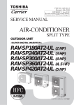
AIR TO WATER HEAT PUMP
SERVICE MANUAL
Model name:
Hydro Unit
Outdoor Unit
HWS-803XWHM3-E(TR)
HWS-803XWHT6-E(TR)
HWS-803XWHD6-E
HWS-803XWHT9-E
HWS-1403XWHM3-E(TR)
HWS-1403XWHT6-E(TR)
HWS-1403XWHD6-E
HWS-1403XWHT9-E(TR)
HWS-803H-E(TR)
HWS-1103H-E(TR)
HWS-1403H-E(TR)
HWS-1103H8-E
HWS-1103H8R-E
HWS-1403H8-E
HWS-1403H8R-E
HWS-1603H8-E
HWS-1603H8R-E
Hot Water Cylinder
HWS-1501CSHM3-E(-UK)
HWS-2101CSHM3-E(-UK)
HWS-3001CSHM3-E(-UK)
Contents
1 SAFETY PRECAUTIONS . . . . . . . . . . . . . . . . . . . . . . . . . . . . . . . . . . . . . . . . . . . . . . . . 3
2 NEW REFRIGERANT (R410A). . . . . . . . . . . . . . . . . . . . . . . . . . . . . . . . . . . . . . . . . . . . 6
2-1.Safety During Installation and Service . . . . . . . . . . . . . . . . . . . . . . . . . . . . . . . . . . . . . . . . . . . . . . . 6
2-2.Installing refrigerant pipe . . . . . . . . . . . . . . . . . . . . . . . . . . . . . . . . . . . . . . . . . . . . . . . . . . . . . . . . . 7
2-2-1.Steel pipe and joint . . . . . . . . . . . . . . . . . . . . . . . . . . . . . . . . . . . . . . . . . . . . . . . . . . . . . . . 7
2-2-2.Processing of piping materials . . . . . . . . . . . . . . . . . . . . . . . . . . . . . . . . . . . . . . . . . . . . . . 8
2-3.Tools . . . . . . . . . . . . . . . . . . . . . . . . . . . . . . . . . . . . . . . . . . . . . . . . . . . . . . . . . . . . . . . . . . . . . . . . 10
2-3-1.Necessary tools. . . . . . . . . . . . . . . . . . . . . . . . . . . . . . . . . . . . . . . . . . . . . . . . . . . . . . . . . 10
2-4.Recharging of refrigerant . . . . . . . . . . . . . . . . . . . . . . . . . . . . . . . . . . . . . . . . . . . . . . . . . . . . . . . . 11
2-5.Brazing of pipes . . . . . . . . . . . . . . . . . . . . . . . . . . . . . . . . . . . . . . . . . . . . . . . . . . . . . . . . . . . . . . . 13
2-5-1.Materials of brazing . . . . . . . . . . . . . . . . . . . . . . . . . . . . . . . . . . . . . . . . . . . . . . . . . . . . . . 13
2-5-2.Flux . . . . . . . . . . . . . . . . . . . . . . . . . . . . . . . . . . . . . . . . . . . . . . . . . . . . . . . . . . . . . . . . . . 13
2-5-3.Brazing . . . . . . . . . . . . . . . . . . . . . . . . . . . . . . . . . . . . . . . . . . . . . . . . . . . . . . . . . . . . . . . 13
3 Specifications . . . . . . . . . . . . . . . . . . . . . . . . . . . . . . . . . . . . . . . . . . . . . . . . . . . . . . . 15
4 Outside Drawing . . . . . . . . . . . . . . . . . . . . . . . . . . . . . . . . . . . . . . . . . . . . . . . . . . . . . 18
4-1.Hydro unit . . . . . . . . . . . . . . . . . . . . . . . . . . . . . . . . . . . . . . . . . . . . . . . . . . . . . . . . . . . . . . . . . . . . 18
4-2.Outdoor unit . . . . . . . . . . . . . . . . . . . . . . . . . . . . . . . . . . . . . . . . . . . . . . . . . . . . . . . . . . . . . . . . . . 19
4-3.Hot water cylinder . . . . . . . . . . . . . . . . . . . . . . . . . . . . . . . . . . . . . . . . . . . . . . . . . . . . . . . . . . . . . . 21
5 Wiring Diagram . . . . . . . . . . . . . . . . . . . . . . . . . . . . . . . . . . . . . . . . . . . . . . . . . . . . . . 22
5-1.Hydro Unit. . . . . . . . . . . . . . . . . . . . . . . . . . . . . . . . . . . . . . . . . . . . . . . . . . . . . . . . . . . . . . . . . . . . 22
5-2.Outdoor Unit (Single phase Type) . . . . . . . . . . . . . . . . . . . . . . . . . . . . . . . . . . . . . . . . . . . . . . . . . 23
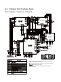
5-3.Outdoor Unit (3 phase type) . . . . . . . . . . . . . . . . . . . . . . . . . . . . . . . . . . . . . . . . . . . . . . . . . . . . . . 24
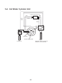
5-4.Hot Water Cylinder Unit . . . . . . . . . . . . . . . . . . . . . . . . . . . . . . . . . . . . . . . . . . . . . . . . . . . . . . . . . 25
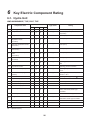
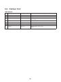
6 Key Electric Component Rating . . . . . . . . . . . . . . . . . . . . . . . . . . . . . . . . . . . . . . . . . 26
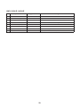
6-1.Hydro Unit. . . . . . . . . . . . . . . . . . . . . . . . . . . . . . . . . . . . . . . . . . . . . . . . . . . . . . . . . . . . . . . . . . . . 26
6-2.Outdoor Unit . . . . . . . . . . . . . . . . . . . . . . . . . . . . . . . . . . . . . . . . . . . . . . . . . . . . . . . . . . . . . . . . . . 28
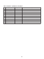
6-3.Hot Water Cylinder Unit . . . . . . . . . . . . . . . . . . . . . . . . . . . . . . . . . . . . . . . . . . . . . . . . . . . . . . . . . 31
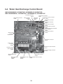
6-4.Water Heat Exchange Control Board . . . . . . . . . . . . . . . . . . . . . . . . . . . . . . . . . . . . . . . . . . . . . . . 32
6-5.Outdoor Control Board (Single phase Type) . . . . . . . . . . . . . . . . . . . . . . . . . . . . . . . . . . . . . . . . . 33
6-6.Outdoor Unit Control (3 phase type). . . . . . . . . . . . . . . . . . . . . . . . . . . . . . . . . . . . . . . . . . . . . . . . 35
MCC-1596 (Compressor IPDU) . . . . . . . . . . . . . . . . . . . . . . . . . . . . . . . . . . . . . . . . . . . . . . . . . 35
MCC-1597 (Fan Motor IPDU) . . . . . . . . . . . . . . . . . . . . . . . . . . . . . . . . . . . . . . . . . . . . . . . . . . . 36
MCC-1599 (Interface (CDB)) . . . . . . . . . . . . . . . . . . . . . . . . . . . . . . . . . . . . . . . . . . . . . . . . . . . 37
MCC-1600 (Noise Filter). . . . . . . . . . . . . . . . . . . . . . . . . . . . . . . . . . . . . . . . . . . . . . . . . . . . . . . 38
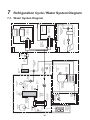
7 Refrigeration Cycle / Water System Diagram . . . . . . . . . . . . . . . . . . . . . . . . . . . . . . 39
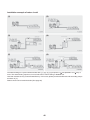
7-1.Water System Diagram . . . . . . . . . . . . . . . . . . . . . . . . . . . . . . . . . . . . . . . . . . . . . . . . . . . . . . . . . 39
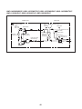
7-2.Refrigeration Cycle System Diagram . . . . . . . . . . . . . . . . . . . . . . . . . . . . . . . . . . . . . . . . . . . . . . . 41
1
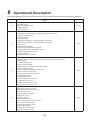
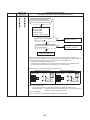
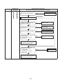
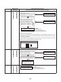
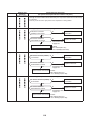
8 Operational Description . . . . . . . . . . . . . . . . . . . . . . . . . . . . . . . . . . . . . . . . . . . . . . . 43
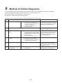
9 Method of Defect Diagnosis . . . . . . . . . . . . . . . . . . . . . . . . . . . . . . . . . . . . . . . . . . . . 81
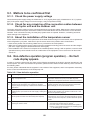
9-1.Matters to be confirmed first . . . . . . . . . . . . . . . . . . . . . . . . . . . . . . . . . . . . . . . . . . . . . . . . . . . . . . 82
9-1-1.Check the power supply voltage . . . . . . . . . . . . . . . . . . . . . . . . . . . . . . . . . . . . . . . . . . . . 82
9-1-2.Check for any miswiring of the connection cables between the hydro unit and the
outdoor unit . . . . . . . . . . . . . . . . . . . . . . . . . . . . . . . . . . . . . . . . . . . . . . . . . . . . . . . . . . . . 82
9-1-3.About the installation of the temperature sensor. . . . . . . . . . . . . . . . . . . . . . . . . . . . . . . . 82
9-2.Non-defective operation (program operation) … No fault code display appears.. . . . . . . . . . . . . . 82
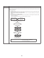
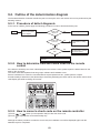
9-3.Outline of the determination diagram . . . . . . . . . . . . . . . . . . . . . . . . . . . . . . . . . . . . . . . . . . . . . . . 83
9-3-1.Procedure of defect diagnosis. . . . . . . . . . . . . . . . . . . . . . . . . . . . . . . . . . . . . . . . . . . . . . 83
9-3-2.How to determine from the check code on the remote control . . . . . . . . . . . . . . . . . . . . . 83
9-3-3.How to cancel a check code on the remote controller . . . . . . . . . . . . . . . . . . . . . . . . . . . 83
9-3-4.How to diagnose by error code . . . . . . . . . . . . . . . . . . . . . . . . . . . . . . . . . . . . . . . . . . . . . 84
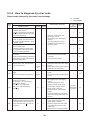
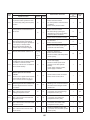
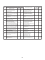
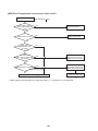
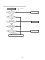
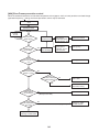
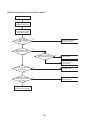
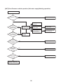
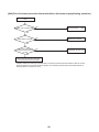
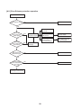
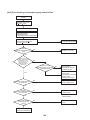
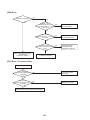
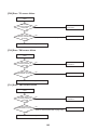
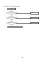
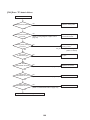
9-4.Diagnosis flow chart for each error code . . . . . . . . . . . . . . . . . . . . . . . . . . . . . . . . . . . . . . . . . . . . 91
9-4-1.Hydro unit failure detection . . . . . . . . . . . . . . . . . . . . . . . . . . . . . . . . . . . . . . . . . . . . . . . . 91
9-4-2.Outdoor Unit Failure Detection . . . . . . . . . . . . . . . . . . . . . . . . . . . . . . . . . . . . . . . . . . . . 109
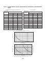
9-4-3.Temperature sensor, temperature-resistance characteristic table . . . . . . . . . . . . . . . . . 122
9-5.Operation check by PC board switch . . . . . . . . . . . . . . . . . . . . . . . . . . . . . . . . . . . . . . . . . . . . . . 123
9-5-1.Operation check mode . . . . . . . . . . . . . . . . . . . . . . . . . . . . . . . . . . . . . . . . . . . . . . . . . . 123
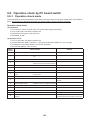
9-6.Brief method for checking the key components . . . . . . . . . . . . . . . . . . . . . . . . . . . . . . . . . . . . . . 124
9-6-1.Hydro unit . . . . . . . . . . . . . . . . . . . . . . . . . . . . . . . . . . . . . . . . . . . . . . . . . . . . . . . . . . . . 124
9-6-2.Outdoor unit . . . . . . . . . . . . . . . . . . . . . . . . . . . . . . . . . . . . . . . . . . . . . . . . . . . . . . . . . . 125
10 Hydro unit and Outdoor Unit Settings . . . . . . . . . . . . . . . . . . . . . . . . . . . . . . . . . . . 127
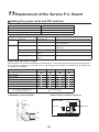
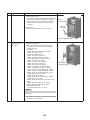
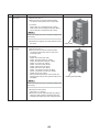
11 Replacement of the Service P.C. Board . . . . . . . . . . . . . . . . . . . . . . . . . . . . . . . . . 152
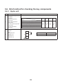
12 How to Exchange Main Parts . . . . . . . . . . . . . . . . . . . . . . . . . . . . . . . . . . . . . . . . . . 153
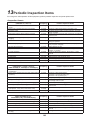
13 Periodic Inspection Items . . . . . . . . . . . . . . . . . . . . . . . . . . . . . . . . . . . . . . . . . . . . . 193
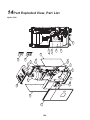
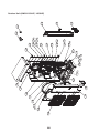
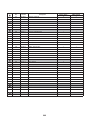
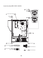
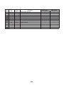
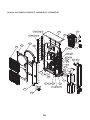
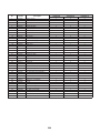
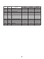
14 Part Exploded View, Part List . . . . . . . . . . . . . . . . . . . . . . . . . . . . . . . . . . . . . . . . . . 194
2
1
SAFETY PRECAUTIONS
The unit and this service guide list very important safety precautions.
Understand the following details (indications and symbols) before reading the body text, and follow the instructions.
[About indication]
Indication
Meaning of Indication
DANGER
Indicates that a wrong operation may cause a service engineer and the third persons
around to get fatal or serious injuries.
WARNING
Indicates that a wrong operation may cause a service engineer and the third persons
around to get fatal or serious injuries, or that unit defective after the operation may cause
a user to have a similar serious accident.
CAUTION
Indicates that a wrong operation may cause a service engineer and the third persons
around to get injuries or may cause property damage*, or that unit defective after the
operation may cause a user to have a similar accident.
* Property damage indicates extended damage to property, furniture, livestock, or pets.
[About symbols]
Symbols
Meaning of Symbols
Indicates a forbidden action.
Specific forbidden actions are described in text near the symbol.
Indicates a forcible (must do) action.
Specific forcible actions are described in text near the symbol.
Indicates a caution (including danger and warning).
Specific cautions are described in picture or text inside or near the symbol.
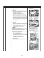
DANGER
<Turn off the power breaker>
Turn off the power breaker before removing the front panel and cabinet.
• Failure to do so may cause a high voltage electric shock, leading to death or injury.
• During an operation, the second side circuit of high pressure transmission(*) are applied with a high voltage of 230V
or higher.
• Touching the circuit even with an electrical insulator, let alone a bare hand or body, causes an electric shock.
: For details, see the schematic.
<Discharge between terminals>
When the front panel and cabinet are removed, make short-circuit current to discharge between high pressure
capacitor terminals.
• Failure to do so may cause a high voltage electric shock, leading to death or injury.
• After the power is turned off, the high pressure capacitor is still charged with high voltage.
<Forbidden>
Do not turn on the power breaker after removing the front panel cabinet.
• Failure to do so may cause a high voltage electric shock, leading to death or injury.
WARNING
<Check earth ground>
Before starting failure diagnosis or repair, check that the ground wire () is connected to the unit ground terminal.
• An unconnected ground wire could cause an electric shock if electric leakage occurs.
• If the earth ground is not properly connected, ask an electrical worker for rework of the ground connection.
: Ground wire of class D grounding
3
WARNING
<No modification>
Do not modify the unit.
• Do not disassemble or modify the parts also.
• A fire, an electric shock, or an injury may occur.
<Use specified parts>
Use the specified parts () when replacing them.
• Using parts other than specified ones may cause a fire or an electric shock.
: For details, see the parts price list.
<Keep children away from unit>
Keep any person (including children) other than service engineers away from a failure diagnosis or repairing place.
• A tool or disassembled parts may cause an injury.
• Advise the customer to keep the third persons (including children) away from the unit.
<Insulation treatment>
After connecting a cut lead with a crimp contact, discharge by facing the closed side upward.
• Connect lead wires with crimping terminals and turn the closed end upwards to avoid exposure to water.
<Watch out for fire>
Observe the following instructions when repairing the refrigerant cycle.
(1) Watch out for surrounding fire. Always put out the fire of stove burner or other devices before starting the repair.
Should the fire fail to be put out, the oil mixed with refrigerant gas could catch fire.
(2) Do no use a welder in a closed room.
A room with no ventilation may cause carbon monoxide poisoning.
(3) Keep away flammable materials.
The materials may catch the fire of a welder.
<Use refrigerant carefully>
Check the refrigerant name to use the tools and members appropriate for the refrigerant.
• A product using the refrigerant R410A has the refrigerant name prominently displayed on its outdoor unit. In
addition, the diameter of the service port is changed from that of the conventional R22 to prevent incorrect filling.
Never use refrigerant other than R410A for Air to Water Heat Pump using R410A. Also, never use R410A for Air to
Water Heat Pump using other refrigerant (such as R22).
• A mixture of R410A with different ones excessively raises the pressure in the refrigerant cycle, leading to an injury
due to burst.
Do not make additional charge of the refrigerant.
• An additional charge when refrigerant gas leaks changes the refrigerant composition in the refrigerant cycle,
causing the characteristics change of the Air to Water Heat Pump or excessive high pressure in the refrigerant
cycle with more than the specified amount of refrigerant charged. This may cause burst or an injury. If the
refrigerant gas leaks, perform refrigerant recovery or other operation to make the Air to Water Heat Pump contain
no refrigerant, and then perform vacuuming. After that, refill the unit with the defined amount of liquid refrigerant.
Never charge refrigerant exceeding the amount specified.
When the refrigerant cycle is refilled with refrigerant, do not enter air or refrigerants other than the specified
refrigerant, R410A.
• A mixture of R410A with air or an inappropriate substance causes excessive high pressure inside the refrigerant
cycle, leading to an injury due to burst.
Check that there is no refrigerant gas leak after the installation is completed.
• If it catches fire of a fan heater, a space heater, or a stove, poisonous gases may be produced.
<Be careful with wiring>
After a repair is completed, be sure to reassemble the parts and put the wiring back to its original state. In addition,
be careful with the internal wiring not to be caught in a cabinet or panel.
• A defective assembly or wiring may cause a disaster at a customer site due to electrical leakage or a fire.
<Check for water leak>
After the repair of a water pathway is completed, check that there is no water leak.
• In using the product, water leak may cause a fire at a customer site due to electrical leakage or an electric shock.
4
WARNING
<Check insulation>
After the work is completed, check with an insulating-resistance tester (500V) that the insulation resistance between
the live and dead-metal parts is 2 M: or higher.
• A low insulation resistance may cause a disaster at a customer site due to electrical leakage or an electric shock.
<Ventilate>
Ventilate if refrigerant gas leaks during service work.
• Should refrigerant gas catch fire, poisonous gases may be produced. A closed room full of leaking refrigerant
results in the absence of oxygen; it is dangerous. Make sure to ventilate.
<Caution: electric shock>
When checking a circuit while energized if necessary, use rubber gloves not to contact the live part.
• Contact with the live part may cause an electric shock.
• The unit contains high-voltage circuits. Contact with a part in the control board with your bare hand may cause an
electric shock. Take enough care to check circuits.
<Turn off the power breaker>
Because the electrical components are energized with high voltage, always turn off the power breaker before
starting to work.
• Failure to do so may cause an electric shock.
<Always do>
Should refrigerant gas leak, find where the gas leaks and properly repair it.
• To stop the repair work because the leakage location cannot be identified, perform refrigerant recovery and close
the service valve. Failure to do so may cause the refrigerant gas to leak in a room. Although refrigerant gas alone
is harmless, if it catches fire of a fan heater, a space heater, or a stove, poisonous gases may be produced.
When installing the unit or re-installing it after relocation, follow the installation guide for proper operation.
• A defective installation may cause a refrigerant cycle defective, a water leak, an electric shock, or a fire.
<Check after repair>
After a repair is completed, check for any abnormality.
• Failure to do so may cause a fire, an electric shock, or an injury.
• Turn off the power breaker to perform check.
After a repair is completed (and the front panel and cabinet are placed), make a test run to check for any abnormality
such as smoke or abnormal sound.
• Failure to do so may cause a fire or an electric shock. Place the front panel and cabinet before making a test run.
<Check after re-installation>
Check that the following are properly performed after re-installation.
(1) The ground wire is properly connected.
(2) The installation is stable without any tilt or wobbles.
Failure to check them may cause a fire, an electric shock, or an injury.
CAUTION
<Wear gloves>
Wear gloves () when performing repair.
• Failure to do so may cause an injury when accidentally contacting the parts.
: Thick gloves such as cotton work gloves
<Cooling check>
Perform service work when the unit becomes cool enough after the operation.
• High temperature of compressor piping or other equipment after a cooling or heating operation may cause burn.
<Tighten with torque wrench>
Tighten a flare nut with a torque wrench in the specified method.
• A flare nut tightened too much might crack after a long period, causing refrigerant leak.
5
2
NEW REFRIGERANT (R410A)
This Air to Water Heat Pump adopts a new refrigerant HFC (R410A) to prevent destruction of the ozone layer.
The working pressure of R410A refrigerant is 1.6 times higher than that of the conventional refrigerant R22.The
refrigerant oil is also changed for the new refrigeration. Therefore, during installation or service work, be sure that
water, dust, former refrigerant, or refrigeration machine oil does not enter the refrigerant cycle of the new type
refrigerant Air to Water Heat Pump. A wrong installation or service operation may cause a serious accident.
Read carefully the following instructions to use the tools or members for R410A for safety work.
2-1. Safety During Installation and Service
• Use only the refrigerant R410A for Air to Water Heat Pump using R410A.
A mixture of R410A with different ones excessively raises the pressure in a refrigerant cycle, leading to an injury
due to burst.
• Check the refrigerant name to use the tools and members appropriate for the refrigerant.
A product using the refrigerant R410A has the refrigerant name prominently displayed on its outdoor unit. In
addition, the diameter of the service port is changed from that of the conventional R22 to prevent incorrect filling.
• Ventilate if refrigerant gas leaks during service work.
Should refrigerant gas catch fire, poisonous gases may be produced. A closed room full of leaking refrigerant
results in the absence of oxygen; it is dangerous. Make sure to ventilate.
• When the refrigerant cycle is refilled with refrigerant, do not mix air or refrigerants other than the specified
refrigerant, R410A.
A mixture of R410A with air or an inappropriate substance causes excessive high pressure inside the refrigerant
cycle, leading to an injury due to burst.
• Check that no refrigerant gas leaks after the installation is completed.
Should a refrigerant gas leak in a room and catch fire, poisonous gases may be produced.
• When installing the unit that contains large amount of refrigerant such as Air to Water Heat Pump, take measures
to prevent the refrigerant from exceeding the threshold concentration in case it leaks.
Should leaking refrigerant exceed the threshold concentration could cause an accident due to oxygen deficient.
• When installing the unit or re-installing it after relocation, follow the installation guide for proper operation.
A defective installation may cause a refrigerant cycle defective, a water leak, an electric shock, or a fire.
• Do not modify the product. Do not disassemble or modify the parts also.
A fire, an electric shock, or an injury may occur.
6
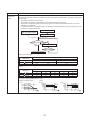
2-2. Installing refrigerant pipe
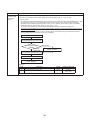
2-2-1. Steel pipe and joint
For refrigerant piping, steel pipe and joints are mainly used. Select those comply with JIS (Japanese Industrial
Standards) for a service work. Also, use such clean piping materials that less impurities attach to the inside of pipe
and joints.
Copper pipe
Use copper pipe of the “copper and copper alloy seamless pipe” type with attach oil quantity of 40 mg / 10 m or less.
Do not use pipe that is cracked, distorted, or discoloured (especially inside).The expansion valve or capillary may
get clogged with impurities.
Considering that Air to Water Heat Pump using R410A is higher in pressure than those using the conventional R22,
be sure to select the material that comply with the standard.
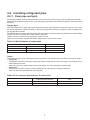
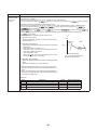
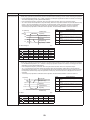
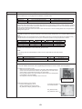
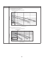
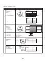
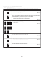
Table 2-1 shows the thickness of copper pipe used for R410A.
Never use commercially available thin-walled copper pipe of 0.8 mm thick or less.
Table 2-1 Wall thickness of copper pipe
Wall thickness (mm)
Nominal diameter
Outer diameter
R410A
3/8
9.52
0.80
5/8
15.88
1.00
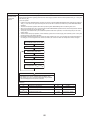
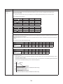
Joints
For the joint of copper pipe, flared joint and socket joint are used. Remove impurities from a joint before using it.
• Flared joint
A flared joint cannot be used for the copper pipe whose outer diameter is 20 mm or larger. A socket joint can be
used instead in that case.
Table 2-2-3 and 2-2-4 show the dimensions of flare pipe, the end of flared joint, and flare nuts.
• Socket joint
A socket joint is used to connect the thick-walled pipe of mainly 20 mm or larger in diameter.
Table 2-2 shows the wall thickness of socket joints.
Table 2-2 The minimum wall thickness of socket joints
Nominal diameter
Reference of outer diameter of
copper pipe connected (mm)
Minimum joint wall thickness
(mm)
3/8
9.52
0.80
5/8
15.9
1.00
7
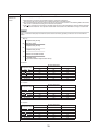
2-2-2. Processing of piping materials
When installing refrigerant pipe, prevent water or dust from entering the pipe, and do not use oil other than lubricant
used for Air to Water Heat Pump. Make sure that no refrigerant leak occurs.
If piping needs lubrication, use lubricating oil whose water content is removed.
After the oil is put in, be sure to seal the container with airproof cover or other covers.
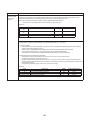
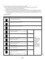
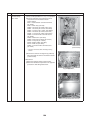
Flare and precautions
1) Cut a pipe.
Cut slowly with a pipe cutter so that the pipe is not distorted.
2) Remove burr and flaw.
A burr or flaw in a flare part may cause refrigerant leak. Remove carefully all the burrs, and clean up the
cut ends before installation.
3) Insert a flare nut.
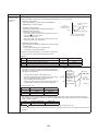
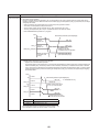
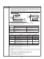
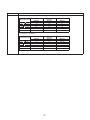
4) Flare
Figure 2-2-1
Check that the clasps and copper pipe are clean. Flare
Flare dimension
correctly using the clasp. Use a flare tool for R410A or the
D
conventional one. Flare processing dimension varies
A
depending on the flare tool type. When using the
conventional flare tool, use a gauge for size adjustment
to secure the A dimension.
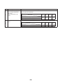
Table 2-2-3 Flare processing related dimension for R410A
A (mm)
Nominal
diameter
Outer diameter
(mm)
Wall thickness
(mm)
3/8
9.52
5/8
15.9
Conventional flare tool
Flare tool for R410A
clutch type
Clutch type
Butterfly-nut type
0.8
0 to 0.5
1.0 to 1.5
2.0 to 2.5
1.0
0 to 0.5
1.0 to 1.5
2.0 to 2.5
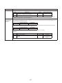
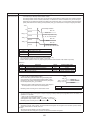
Table 2-2-4 Dimension of flare for R410A and flare nut
Dimension (mm)
Nominal
diameter
Outer diameter
(mm)
Wall thickness
(mm)
A
B
3/8
9.52
0.8
13.0
13.2
5/8
15.9
1.0
19.1
19.7
D
Flare nut width
(mm)
9.7
20
18
15.9
24.5
26
C
Figure 2-2-2 Relationship between flare nut and flare surface
45°
6°
-4
B A
C
43°
- 45
°
8
D
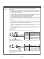
Flare connecting procedure and precautions
1) Make sure that the flare and connecting portions do not have any flaw and dust.
2) Correctly align the flared surface and the connecting axis.
3) Tighten the flare with designated torque by means of a torque wrench. The tightening torque for R410A is
the same as that for the conventional R22. If the torque is weak, gas leakage may occur. If it is too strong,
the flare nut may crack and may be made non-removable. When choosing the tightening toque, comply
with values designated by products. Table 2-2-5 shows reference values.
NOTE
When applying oil to the flare surface, be sure to use oil designated by the product. Using any other oil deteriorates
the lubricating oil, possibly causing the compressor to burn out.
Table 2-2-5 Tightening torque of flare for R410A (Reference values)
Nominal diameter
Outer diameter (mm)
Tightening torque N•m (kgf•m)
3/8
9.52
33 to 42 (3.3 to 14.2)
5/8
15.9
66 to 82 (6.8 to 8.2)
9
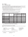
2-3. Tools
2-3-1. Necessary tools
In Air to Water Heat Pump using R410A, the service port diameter of packed valve of the outdoor unit is changed
to prevent mixing of other refrigerant. To reinforce the pressure resistance, flare dimensions and opposite side
dimensions of flare nut (For Ø 12.7 copper pipe) of the refrigerant piping are lengthened.
Because the refrigerating machine oil is changed, mixing of oil may generate sludge, clog capillary, or cause other
problems. Accordingly, the tools to be used include:
• tools dedicated for R410A (Those that cannot be used for the conventional refrigerant, R22)
• tools dedicated for R410A, but can be also used for the conventional refrigerant, R22
• tools that can be used for the conventional refrigerant, R22.
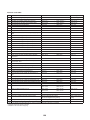
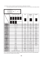
The following table shows the tools dedicated for R410A and their interchangeability.
Tools dedicated for R410A (The following tools must be for R410A)
Tools whose specifications are changed for R410A and their interchangeability
R410A Air to Water Hear Pump
installation
No.
Tool to be used
Usage
Conventional refrigerant
Air to Water Heat Pump
installation
For R410A
Existence of new
equipment
Conventional
equipment can be
used
New equipment can be
used with conventional
refrigerant
1
Flare tool
Pipe flaring
Yes
*(Note 1)
Yes
2
Copper pipe gauge for
adjusting projection margin
Flaring by conventional
flare tool
Yes
*(Note 1)
*(Note 1)
3
Torque wrench (For Ø15.9)
Connection of flare nut
Yes
No
No
4
Gauge manifold
5
Charge hose
Evacuating, refrigerant
charge, run check, etc.
Yes
No
No
6
Vacuum pump adapter
Vacuum evacuating
Yes
No
Yes
7
Electrical balance for
refrigerant charging
Refrigerant charge
Yes
No
Yes
8
Refrigerant cylinder
Refrigerant charge
Yes
No
No
9
Leakage detector
Gas leakage check
Yes
No
Yes
10
Charging cylinder
Refrigerant charge
*(Note 2)
No
No
* (Note 1) Flaring for R410A by using the conventional flare tool requires projection margin adjustment. This
adjustment requires copper pipe gauge or other instrument.
* (Note 2) A charging cylinder for R410A is currently under development.
General tools (Conventional tools are available)
In addition to the above dedicated tools, the following equipment also available for R22 is necessary as the general
tools.
1. Vacuum pump
Use this by attaching vacuum pump
adapter.
2. Torque wrench (For Ø6.35)
3. Pipe cutter
4.
5.
6.
7.
8.
Reamer
Pipe bender
Level vial
Screwdriver (+, –)
Spanner or Monkey wrench
Also prepare the following equipment for other work methods or run check.
1. Clamp meter
2. Thermometer
3. Insulation resistance meter
4. Electroscope
10
9. Hole core drill (Ø65)
10. Hexagon wrench
(Opposite side 4mm)
11. Tape measure
12. Metal saw
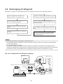
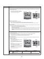
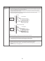
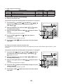
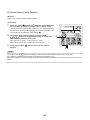
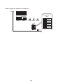
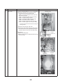
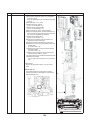
2-4. Recharging of refrigerant
Recharge, if necessary, the specified amount of new refrigerant according to the following procedure.
Recover the refrigerant, and check that no
refrigerant remains in the refrigerant cycle.
Open fully the handle of gauge manifold Lo, turn on the
vacuum pump, and then perform vacuum evacuating.
Connect the charge hose to packed valve service
port on the outdoor unit's gas side.
When the compound gauge's pointer indicates
-0.1 MPa (-76cmHg), close fully the handle Lo and turn
off the vacuum pump.
Connect the charge hose to the vacuum pump
adapter.
Let the equipment stay as it is for one to two minutes
and check that the compound gauge pointer does not
return.
Open fully both packed valves on the liquid and
gas sides.
Place the refrigerant cylinder to the electronic balance,
connect the connecting hose to the cylinder and the
connecting port of the electronic balance, and then
charge liquid refrigerant.
(For refrigerant charging, see the figure below)
NOTE
• Never charge refrigerant exceeding the specified amount.
• If the specified amount of refrigerant cannot be charged, charge it a little at a time while running refrigerant
recovery (pump down).
• Do not make additional charging.
An additional charge when refrigerant leaks changes the refrigerant composition in the refrigerant cycle,
causing the characteristics change of the Air to Water Heat Pump or excessive high pressure in the refrigerant
cycle with more than the specified amount of refrigerant charged. This may cause burst or an injury.
Fig. 2-4-1 Configuration of refrigerant charging
(Hydro unit)
(Outdoor unit)
Open
Refrigerant cylinder (with siphon)
Check valve
Open
Open Close
Open/close valve
for charging
Service port
Electronic balance for refrigerant charging
11
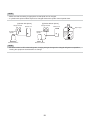
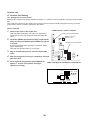
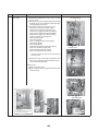
NOTE
• Make sure that the setting is appropriate so that liquid can be charged.
• A cylinder with siphon enables liquid to be charged without the cylinder turned upside down.
[Cylinder with siphon]
Gauge manifold
Outdoor unit
Refrigerant
cylinder
Electronic balance
[Cylinder without siphon]
Gauge manifold
Outdoor unit
Siphon pipe
Refrigerant
cylinder
Electronic balance
NOTE
• Because R410A is HFC mixed refrigerant, charging with gas changes the charged refrigerant composition,
causing the equipment characteristics to change.
12
2-5. Brazing of pipes
Type of flux
• Non-corrosive flux
It is generally a compound of borax and boric acid.
It is effective when brazing temperature is higher
than 800 °C.
• Active solvent
Most of this type of flux is generally used for silver
brazing.
It features the increase of oxide film while moving the
capability to the borax-boric acid compound to add
compounds such as potassium fluoride, potassium
chloride, or sodium fluoride.
2-5-1. Materials of brazing
Silver brazing metal
Silver brazing metal is an alloy mainly composed of
silver and copper.
It uses iron, copper, or copper alloy, and is relatively
expensive though it excels in soldering.
Phosphor bronze brazing metal
Phosphor bronze brazing metal is generally used to
join copper or copper alloy.
Piping materials for brazing and brazing
metal / flux
Low temperature brazing metal
Low temperature brazing metal is generally called
solder, and is an alloy of tin and lead. Do not use it for
refrigerant piping because its adhesive capacity is low.
Piping material
NOTE
• Phosphor bronze brazing metal tends to react with
sulfur, producing a fragile compound water solution.
This may cause gas leakage. Therefore, use other
type of brazing metal at a hot spring resort or similar
place, and coat the surface with coatings.
• To braze the pipe again while performing service
work, use the same type of brazing metal.
Brazing metal to be
Flux to be used
used
Copper - Copper
Phosphor copper
Do not use
Copper - Iron
Silver
Paste flux
Iron - Iron
Silver
Vapour flux
NOTE
• Do not enter flux into the refrigerant cycle.
• If chlorine contained in the flux remains within the
pipe, the lubricating oil deteriorates. Because of
this, use a flux that does not contain chlorine.
• When adding water to the flux, use water that does
not contains chlorine. (e.g. distilled water or ionexchange water)
• Remove the flux after brazing.
2-5-2. Flux
Why flux is necessary
2-5-3. Brazing
• Removing all the oxide film and any foreign matter
on the metal surface assists the flow of brazing
metal.
• Flux prevents the metal surface from being oxidized
in the course of brazing.
• Reducing the brazing metal's surface tension
enables the brazing metal to adhere for better metal
processing.
Brazing must be performed by a person qualified and
experienced with theoretical knowledge since the
operation requires sophisticated techniques.
Perform brazing while flowing dry nitrogen gas (N2) to
prevent oxide film from forming during brazing
application to the inside of the pipe.
NOTE
Characteristics of flux
• Never use gas other than nitrogen gas.
• The activation temperature of flux matches the
brazing temperature.
• A wide effective temperature range makes flux hard
to carbonize.
• It is easy to remove slag after brazing.
• The corrosive action to the treated metal and brazing
metal is minimum.
• The good performance of flux gives no harm to a
human body.
Since flux works in a complicated manner as
described above, select an appropriate type of flux
according to metal treatment type, brazing metal and
brazing method, or other conditions.
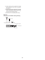
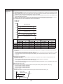
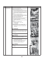
Brazing method to prevent oxidation
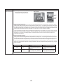
1) Attach a reducing valve and a flow meter to the
nitrogen cylinder.
2) Use a copper pipe to direct the piping material,
and attach the flow meter to the balance.
3) Apply a mark to the clearance between the
piping material and the copper pipe filled with
nitrogen to prevent the back flow of the
nitrogen gas.
4) If the nitrogen gas flows out, be sure to keep
open the piping end.
13
5) Use the reducing valve to adjust the nitrogen
gas flow speed to 0.05 m3/hour or 0.02 MPa
(0.2 kgf/cm2).
6) After the steps above, keep the nitrogen gas
flowing until the pipe cools down to a certain
extent. (Temperature where the pipe is cool
enough to be touched by hands)
7) Remove the flux completely after brazing.
Fig 2-5-1
Prevention of oxidation during brazing
M Flow meter
Stop valve
Nitrogen gas cylinder
From nitrogen cylinder
Nitrogen gas
Pipe
Robber plug
14
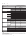
3
Specifications
Unit name
Hydro unit
HWS-803XWHM3-E, 803XWHT6-E, 803XWHD6-E, 803XWHT9-E
Outdoor unit
HWS-803H-E
Heating capacity *1 (kW)
8.0
Cooling capacity *2 (kW)
6.0
Variable range of compressor frequency
10 - 70 Hz
Power source
Single phase 50Hz 220 - 230V
Operation mode
Electric characteristic *1 *2
Heating
Hydro unit
0.98
0.46
Power (kW)
0.101
0.097
91.7
Power factor (%)
91.5
Current (A)
7.64
8.90
Power (kW)
1.719
2.033
Power factor (%)
97.8
99.3
Starting current (A)
8.62
9.36
Hydro unit (dB(A))
29
29
Outdoor unit (dB(A))
49
49
4.40
2.82
Outdoor unit
Total
Operating noise *1 *2 *4
Coefficient of performance *1 *2
Hydro unit
Outer dimension
Height (mm)
925
Width (mm)
525
Depth (mm)
355
Net weight (kg)
50
Color
Silky shade (Munsell 1Y8.5/0.5)
Remote controller
Outer dimension *3
Height (mm)
120
Width (mm)
120
Circulating pump
Motor output (W)
Depth (mm)
16
125 (MAX)
Flow rate (L/min)
22.9
Type
Outer dimension
Plate-type heat exchange
Height (mm)
890
Width (mm)
900
Depth (mm)
320
Net weight (kg)
63
Color
Compressor
Fan motor
Silky shade (Munsell 1Y8.5/0.5)
Motor output (W)
1400
Type
Twin rotary type with DC-inverter variable speed control
Model
DA220A2F-22L
Standard air capacity (m3/min)
Motor output (W)
Refrigerant piping
Outdoor unit
Flare connection
Liquid
Ø9.52
Gas
Ø15.9
Liquid
Ø9.52
Gas
Ø15.9
Maximum length (m)
30
Maximum chargeless length (m)
30
Maximum height difference (m)
±30
Minimum length (m)
Refrigerant
Refrigerant name
Water piping
Pipe diameter
5
R410A
Charge amount (kg)
1.8
R1 1/4
Maximum length (m)
None (Need the flow rate 13 /min or more)
Maximum height difference (m)
±7
Maximum working water pressure (kPa)
Operating temperature range
300
Hydro unit (°C)
5-32
Outdoor unit (°C)
Operating humidity range
Wiring connection
50.0
60
Connection method
Hydro unit
17.2
Non-self-suction centrifugal pump
Heat exchanger
Outdoor unit
Cooling
Current (A)
-20-43
Hydro unit (%)
15-85
Outdoor unit (%)
15-100
Power wiring
3 wires: including ground line (Outdoor unit)
Connecting line
4 wires: including ground line
*1 Heating performance measurement conditions: outside air temperature 7 °C, water supply temperature 30 °C, outlet temperature 35 °C, refrigerant piping length 7.5 m (no height
difference).
*2 Cooling performance measurement conditions: outside air temperature 35 °C, water supply temperature 12 °C, outlet temperature 7 °C, refrigerant piping length 7.5 m (no height
difference).
*3 • The remote controller should be shipped with the hydro unit.
• Use two 1.5-meter wires to connect the hydro unit with the remote controller.
*4 The outdoor unit operating noise is measured at the point of 1m away from the unit back surface centre and 1m high from the ground. The hydro unit operating noise is measured at the
point of 1m away from the unit front surface centre.
The value of the operating noise varies depending on room structure where the unit is installed.
*5 Do not leave the hydro unit at 5 °C or below.
*6 Check the water piping for leakage under the maximum operating pressure.
15
Unit name
Hydro unit
HWS-1403XWHM3-E, 1403XWHT6-E, 1403XWHD6-E, 1403XWHT9-E
Outdoor unit
HWS-1103H-E
HWS-1403H-E
Heating capacity *1 (kW)
11.2
14.0
Cooling capacity *2 (kW)
10.0
11.0
10 - 60Hz
10 - 70 Hz
Variable range of compressor frequency
Power source
Single phase 50Hz 220 - 230V
Operation mode
Electric characteristic *1 *2
Hydro unit
Cooling
Heating
Current (A)
0.63
0.61
0.67
0.63
Power (kW)
0.135
0.130
0.145
0.135
Power factor (%)
93.2
92.7
94.0
93.2
9.94
14.88
13.37
17.47
Power (kW)
2.215
3.39
2.965
3.945
Power factor (%)
96.9
99.1
96.4
98.1
Starting current (A)
10.57
15.49
14.04
18.10
Hydro unit (dB(A))
29
29
29
29
Outdoor unit (dB(A))
49
49
51
51
4.77
2.84
4.50
2.70
Total
Coefficient of performance *1 *2
Hydro unit
Outer dimension
Height (mm)
925
Width (mm)
525
Depth (mm)
355
Net weight (kg)
54
Color
Silky shade (Munsell 1Y8.5/0.5)
Remote controller
Outer dimension *3
Height (mm)
120
Width (mm)
120
Circulating pump
Motor output (W)
Depth (mm)
16
190 (MAX)
Flow rate (L/min)
32.1
Type
Outer dimension
900
Depth (mm)
320
93
Silky shade (Munsell 1Y8.5/0.5)
Motor output (W)
2500
Type
Twin rotary type with DC-inverter variable speed control
Model
DA422A3F-25M
Standard air capacity (m3/min)
Motor output (W)
Refrigerant piping
Outdoor unit
Flare connection
Liquid
Ø9.52
Gas
Ø15.9
Liquid
Ø9.52
Gas
Ø15.9
Maximum length (m)
30
Maximum chargeless length (m)
30
Maximum height difference (m)
±30
Minimum length (m)
Refrigerant
Refrigerant name
Water piping
Pipe diameter
5
R410A
Charge amount (kg)
2.7
R1 1/4
Maximum length (m)
Operating temperature range
None (Need the flow rate 17.5 /min or more)
Maximum height difference (m)
±7
Maximum working water pressure (kPa)
300
Hydro unit (°C)
5-32
Outdoor unit (°C)
Operating humidity range
Wiring connection
103.0
100 × 2
Connection method
Hydro unit
31.5
1340
Width (mm)
Color
Fan motor
40.1
Plate-type heat exchange
Height (mm)
Net weight (kg)
Compressor
28.9
Non-self-suction centrifugal pump
Heat exchanger
Outdoor unit
Cooling
Current (A)
Outdoor unit
Operating noise *1 *2 *4
Heating
-20-43
Hydro unit (%)
15-85
Outdoor unit (%)
15-100
Power wiring
3 wires: including ground line (Outdoor unit)
Connecting line
4 wires: including ground line
*1 Heating performance measurement conditions: outside air temperature 7 °C, water supply temperature 30 °C, outlet temperature 35 °C, refrigerant piping length 7.5 m (no height
difference).
*2 Cooling performance measurement conditions: outside air temperature 35 °C, water supply temperature 12 °C, outlet temperature 7 °C, refrigerant piping length 7.5 m (no height
difference).
*3 • The remote controller should be shipped with the hydro unit.
• Use two 1.5-meter wires to connect the hydro unit with the remote controller.
*4 The outdoor unit operating noise is measured at the point of 1m away from the unit back surface centre and 1m high from the ground. The hydro unit operating noise is measured at the
point of 1m away from the unit front surface centre.
The value of the operating noise varies depending on room structure where the unit is installed.
*5 Do not leave the hydro unit at 5 °C or below.
*6 Check the water piping for leakage under the maximum operating pressure.
16
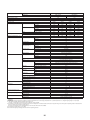
Unit name
Hydro unit
HWS-1403XWHM3-E, 1403XWHT6-E, 1403XWHD6-E, 1403XWHT9-E
Outdoor unit
HWS-1103H8(R)-E
HWS-1403H8(R)-E
HWS-1603H8(R)-E
Heating capacity *1 (kW)
11.2
14.0
16.0
Cooling capacity *2 (kW)
10.0
11.0
13.0
10 - 60Hz
10 - 60 Hz
10 - 70 Hz
Variable range of compressor frequency
Power source
3 phase 50Hz 380 - 400V
Operation mode
Electric characteristic *1 *2
Hydro unit
Outdoor unit
Cooling
Heating
Cooling
Heating
Current (A)
0.63
0.61
0.67
0.63
0.69
0.66
Power (kW)
0.135
0.130
0.145
0.135
0.150
0.140
Power factor (%)
93.2
92.7
94.0
93.2
94.5
92.3
Current (A)
4.03
5.65
5.23
6.50
5.95
7.50
Power (kW)
2.255
3.39
3.065
3.945
3.570
4.660
Power factor (%)
81.1
87.0
84.9
88.0
87.0
90.0
4.66
6.26
6.06
7.13
4.26
8.16
Hydro unit (dB(A))
29
29
29
29
29
29
Outdoor unit (dB(A))
49
50
51
51
52
52
4.69
2.84
4.36
2.70
4.30
2.71
45.8
37.3
Coefficient of performance *1 *2
Hydro unit
Outer dimension
Height (mm)
925
Width (mm)
525
Depth (mm)
355
Net weight (kg)
54
Color
Remote controller
Outer dimension *3
Silky shade (Munsell 1Y8.5/0.5)
Height (mm)
120
Width (mm)
120
Depth (mm)
Circulating pump
16
Motor output (W)
190 (MAX)
Flow rate (L/min)
32.1
Type
Outer dimension
1340
Width (mm)
900
Depth (mm)
320
93
Silky shade (Munsell 1Y8.5/0.5)
Motor output (W)
2500
Type
Twin rotary type with DC-inverter variable speed control
Model
DA422A3F-27M
Standard air capacity (m3/min)
Motor output (W)
Refrigerant piping
Outdoor unit
Flare connection
Liquid
Ø9.52
Gas
Ø15.9
Liquid
Ø9.52
Gas
Ø15.9
Maximum length (m)
30
Maximum chargeless length (m)
30
Maximum height difference (m)
±30
Minimum length (m)
Refrigerant
Refrigerant name
Water piping
Pipe diameter
5
R410A
Charge amount (kg)
2.7
R1 1/4
Maximum length (m)
Operating temperature range
None (Need the flow rate 17.5 /min or more)
Maximum height difference (m)
±7
Maximum working water pressure (kPa)
300
Hydro unit (°C)
5-32
Outdoor unit (°C)
Operating humidity range
Wiring connection
103.0
100 × 2
Connection method
Hydro unit
31.5
Plate-type heat exchange
Color
Fan motor
40.1
Height (mm)
Net weight (kg)
Compressor
28.9
Non-self-suction centrifugal pump
Heat exchanger
Outdoor unit
Cooling
Starting current (A)
Total
Operating noise *1 *2 *4
Heating
-20-43
Hydro unit (%)
15-85
Outdoor unit (%)
15-100
Power wiring
5 wires: including ground line (Outdoor unit)
Connecting line
4 wires: including ground line
*1 Heating performance measurement conditions: outside air temperature 7 °C, water supply temperature 30 °C, outlet temperature 35 °C, refrigerant piping length 7.5 m (no height
difference).
*2 Cooling performance measurement conditions: outside air temperature 35 °C, water supply temperature 12 °C, outlet temperature 7 °C, refrigerant piping length 7.5 m (no height
difference).
*3 • The remote controller should be shipped with the hydro unit.
• Use two 1.5-meter wires to connect the hydro unit with the remote controller.
*4 The outdoor unit operating noise is measured at the point of 1m away from the unit back surface centre and 1m high from the ground. The hydro unit operating noise is measured at the
point of 1m away from the unit front surface centre.
The value of the operating noise varies depending on room structure where the unit is installed.
*5 Do not leave the hydro unit at 5 °C or below.
*6 Check the water piping for leakage under the maximum operating pressure.
17
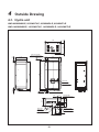
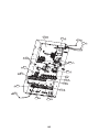
4
Outside Drawing
4-1. Hydro unit
HWS-803XWHM3-E, 803XWHT6-E, 803XWHD6-E, 803XWHT9-E
19.5
HWS-1403XWHM3-E, 1403XWHT6-E, 1403XWHD6-E, 1403XWHT9-E
2-dia.12x17 long hole
(for dia.8-10 anchor bolt)
355
B leg part
9
371.5
380
40 Anchor bolt
long hole pitch
72.5
72.5
960
Anchor bolt long hole pitch
925
20
40.5
352
525
Manometer
20
40
2-dia.12x17 U-shape hole
(for dia.8-10 anchor bolt)
Hot water outlet
connecting pipe 1 1/4"
135.5
116
186.5
19.5
37.5
158
A leg part
259
40.5
54
Remote controler
Drain nipple
Gas line dia.15.88
Water inlet
connecting pipe 1 1/4"
Liquid line dia.9.52
144.5
309.5
18
59.5
17.5
88 burring hole)
17.5
365
118
128
74
581
534
7
Z arrow view
83
327
178
383
Knockout for lower part of piping
60
68
(12-
3 embossed)
52
150
Optional mounting hole
148
165
20
Air inlet
518
178
550
178
900
600
Air outlet
75
34
170
Portion A
80
135
Refrigerant gas
connection
( 15.9 flare)
18
(
18
30
151
80
Mounting bolt hole
12 17 long hole)
Details of portion A
40
Refrigerant liquid
connection
( 9.5 flare)
96
39
55 95
46
25 burring hole)
94
12
Power source intake hole
Refrigerant piping outlet
Indoor and outdoor
connecting line outlet
Name
400
320
12
64
Mounting bolt hole
Details of portion B ( 12 17 U-shape hole)
40
Portion B
890
Drain hole (
24
60
200
Air inlet
95
48
54
155
247
255
5-Drain hole (
7
65
95
55
19
55
380
38 knockout hole
Description
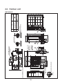
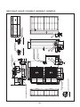
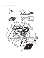
4-2. Outdoor unit
HWS-803H-E
7
Z arrow view
83
Air inlet
150
60
68
52
Knockout for lower part of piping
Optional mounting hole
(24- 3 embossed)
20 88 burring hole)
128
118
17.5
17.5
365
74
655
360
327
178
383
178
518
550
34
170
178
900
70 Portion A
600
Air outlet
75
46
Air inlet
Z
80
135
18
1
2
1
2
18
30
Refrigerant gas connection
( 15.9 flare)
151
80
Mounting bolt hole
( 12 17 long hole)
Details of portion A
40
Refrigerant liquid connection
( 9.5 flare)
39
96
155
534
581
48
54
55 95
121
74
534
581
85
70
Drain hole ( 25 burring hole)
Portion B
605
613
60
55 95
12
Refrigerant piping outlet
Indoor and outdoor
connecting line outlet
Power source intake hole
1
2
Name
400
320
1
12
64
Mounting bolt hole
Details of portion B ( 12 17 U-shape hole)
40
200
94
5-Drain hole (
7
1340
24
20
65
55 95
380
38 knockout hole
Description
HWS-1103H-E, 1403H-E, 1103H8(R)-E, 1403H8(R)-E, 1603H8(R)-E
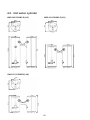
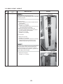
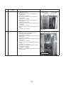
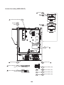
4-3. Hot water cylinder
HWS-2101CSHM3-E(-UK)
HWS-3001CSHM3-E(-UK)
550
595
595
550
2040
2066.6
Specification
for UK only
HWS-1501CSHM3-E(-UK)
Specification
for UK only
1090
1114
595
550
21
1474
1497.6
Specification
for UK only
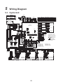
5
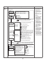
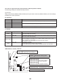
Wiring Diagram
5-1. Hydro Unit
*Option
Remote
controller
(HWS-AMS11E)
THO
BLK
1 2
1 2
WHI
BLK
3
1
1 2 3
3
1
1 2 3
1 2
1 2
BLK
BLK
BLK
1 2
1 2
CN41
(BLU)
BLK
BLK
BLK
BLK
WHI
GRY
TFI
A B
6A 6B 6C 6D TB 06
BRW
BRW
GRY
WHI
TTW
23 4
23 4
1 2
1 2
3
1
1 2 3
Symbol
*Option
1 23 4
23 4
TB 07 7A 7B
BLU : BLUE
GRN : GREEN
ORN : ORANGE
RED : RED
YEL : YELLOW
2
1 2 3 4
1 2
1 2
3
1
1 2 3
CN212
(WHI)
CN214
(WHI)
CN213
(WHI)
CN203 CN204 CN205 CN206 CN207
(YEL) (BRW) (RED) (WHI) (BLU)
9 9
8
7 7
6
BRW
5 5
4
3
2
WHI
1 1
CR10
RY
10
RY
11
BLU
CR12
RY
12
RY
13
CR13
5
4
3
2
1
CN02
(WHI)
5
4
3
2
1
6
RED
5 5
BLU
4 4
ORN
3 3
GRN
2 2
BRW
1 1
CN501
(YEL)
CN01
(WHI)
F01 (5A)
BLK
1 1
PJ20
CN210
(RED)
YEL
1 1
YEL
2 2
YEL
3 3
YEL
4 4
1
2
3
4
1
2
3
4
PJ17
ON
YEL
1
YEL
2
YEL
3
YEL
4
1
2
3
4
1
2
3
4
PJ17
1
2
3
4
CN211
(BLK)
SW02
WHI
05
YEL
WHI
3 3
1 1
CN601
(RED)
7 7
SW10
ON
5 5
SW 11
ON
1 2 3 4
RY602
RED
A2 RY A1
RY600
1 2 3 4
1 2 3 4
WHI
ON
ON
1 2 3 4
41 42 43 44 TB 04
RY604
CN200
(RED)
YEL
1 1
GRN
2 2
RED
3 3
CN201
(WHI)
BLK
1 1
BLK
2 2
CN202
(YEL)
BLK
1 1
2
BLK
3 3
CN102
(WHI)
1
2
3
4
5
6
1 2 3 4
SW07
1 2
CN602
(WHI)
ORN
PNK
RED
RY603
WHI
WHI
YEL
RED
BRW
BLU
RY605
RY607
RY606
CN101
(WHI)
1
2
3
4
5
6
6
*See DIP SW13_1
5
MIXV
Type 2
(3-wire SPST type)
Type 2
(3-wire SPST type)
PNK
ORN
4
6
RY
01
A1
6
1
5
3
3
1
1
WHI
3
3
8
RY
03
7
A2
RY
02
4
3
3
WHI
Photocoupler input
p.c.board
(MCC-1214)
WHI
*1
Emergency stop I/P
3
2
1
Cooling thermostat I/P
Heating thermostat I/P
TB1
2 2
1 1
Flow switch
Pressure switch
4.15MPa
3 3
1. The one-dot chain line indicates
wiring at the local site, and the
dashed line indicates accessories
sold separately and service wires,
respectively.
, and
indicates the terminal
2.
board and the numberals ndicate the
terminal numbers.
3.
indicates P.C. board.
* Be sure to fix the electric
parts cover surely with screws.
(Otherwise water enters into the box
resulting in malfunction.)
Thermal protector
(auto) 75 5
BRW
BRW
RED
RED
ORN
ORN
WHI
WHI
P100 BLK
: Installed
*1 HWS-803XWHT6TR
HWS-1403XWHT6TR : Installed
HWS-803XWHD6-E : Installed
HWS-1403XWHD6-E : Installed
HWS-803XWHT9-E : Installed
HWS-1403XWHT9-E : Installed
HWS-803XWHM3-E : Not installed
HWS-1403XWHM3-E : Not installed
A2
3
2
1
TB1
: Installed
*1 HWS-803XWHT6-E
HWS-1403XWHT6-E : Installed
A1
RY
04
4
Defrost O/P
TB1
Photocoupler input
p.c.board
(MCC-1214)
1 1
Compressor operation
O/P
4
3
2
1
K2
HWS-1403XWHT9TR : Installed
HWS-803XWHM3TR : Not installed
HWS-1403XWHM3TR : Not installed
GRY
*Option
Power supply
220 - 230V~ 50Hz
Hot water cylinder
Power supply
380 - 400V 3N~ 50Hz
HWS-803XWHT9-E
HWS-1403XWHT9-E
HWS-1403XWHT9TR
1L1 3L2 5L3
1L1 3L2 5L3
2T1 4T2 6T3
2T1 4T2 6T3
L1 L2 L3 N TB 02
Power supply
380 - 400V 3N~ 50Hz
HWS-803XWHT6-E
HWS-1403XWHT6-E
HWS-803XWHT6TR
HWS-1403XWHT6TR
22
L
N TB 02
HWS-803XWHM3-E
HWS-1403XWHM3-E
HWS-803XWHM3TR
HWS-1403XWHM3TR
BLU
F3,F4
Fuse
AC250V
T30A
Power supply
220 - 230V~ 50Hz
L1 L2
BLU
BLU
BRW
F3 F4 F5 F6
F3 F4
F3~6
Fuse
AC250V
T30A
BLK
BLK
BLU
RY04
2T1 4T2 6T3
BLU
BLU
BLK
BLU
BLK
BLU
BLU
GRY
BLK
L1 L2 L3 N TB 02
1 2
2T1 4T2 6T3
F3 F4 F5 F6
F3~8
Fuse
AC250V
T30A
RY02
RY04
BLK
Backup heater 1
Backup heater 2
RY02
1L1 3L2 5L3
1L1 3L2 5L3
2T1 4T2 6T3
BLU
BLU
BRW
GRY
2T1 4T2 6T3
F3 F4 F5 F6 F7 F8
BLU
BLU
BRW
L N
YEL/GRN
F1, F2
Fuse
AC250V
T30A
2T1 4T2 6T3
BRW
BLU
BRW
BLU
BRW
TB 03 31 32
RY02
1L1 3L2 5L3
RY04
2T1 4T2
F1 F2
Backup heater 3
Thermal protector
(Single operation)95 5
BLU
1L1 3L2 5L3 RY02 1L1 3L2 5L3
Thermal protector
(Single operation)
95 5
Thermal protector
(Single operation)
95 5
Backup heater 1
BLU
RY05
Thermal protector
(Single operation)
95 5
Backup heater 1
Backup heater 2
BRW
1L1 3L2
BLU
Power supply
220 - 230V~ 50Hz
or
380 - 400V~ 50Hz
Thermal protector
(Single operation)
95 5
Thermal protector
(Single operation)
95 5
Backup heater 1
Backup heater 2
BLU
Thermal protector
(Single operation)
95 5
Thermal protector
(Single operation)
95 5
Outdoor unit
BRW
1 2 3
BRW
11 12 13 TB 01
BRW
WHI
Type 3
(3-wire SPDT type)
RED
2
7
RY
06
8
RED
3WV
1
1
RED
3
3
GRY
BLK
1
1
PNK
1
1
WHI
3
3
ORN
5
5
F100
Fuse
T5A
250V~
CN305 CN100
(GRN) (WHI)
CN606
(BLU)
WHI
7
7
WHI
41 42 43 44 TB 04
CN605
(YEL)
YEL
ORN
CN604
(BLU)
RED
57 58 59 TB 05
WHI
RED
YEL
WHI
RED
3WV
Type 1
(2-wire spring return)
PNK
MIXV
Type 1
(3-wire SPDT type)
BH
TB1
K1
Relay
p.c.board
(MCC-1217)
7 RY
01 8
Boiler control O/P
Alerm O/P
Transformer
1 1
3 3
WPM 2WV
K2
BRW
YEL
51 52 53 54 55 56 57 58 59 TB 05
1 1
SW13
SW06
ON
3
RED
WHI WHI
SW12
4
3
2
1
K1
Relay
p.c.board
(MCC-1217)
GRN
1 1
1 1
GRN
2 2
2 2
GRN
3 3
3 3
GRN
4 4
4 4
ON
BRW
L L
CN603
(YEL)
OFF
WPM N N
3 3
Parts name
Water heat exchanger temperature sensor
Water heat exchanger inlet temperature sensor
Water heat exchanger outlet temperature sensor
Backup heater outlet temperature sensor
Hot water cylinder temperature sensor
Floor heating inlet temperature sensor
Terminal block
TC
TWI
TWO
THO
TTW
TFI
TB
PJ20
CN209
(GRN)
SW14
SW01
BLU
GRN
1 1
1
GRN
2
2 2
GRN
3 3
3
GRN
4 4
4
1
2
3
4
CN208
(BLU)
1
Relay
p.c.board
(MCC-1431)
Symbol
Water pump motor
3-way valve (local)
2-way valve (local)
Mixing valve (local)
Booster heater
Relay01~Relay06
Low pressure sensor
Heater AC230V, 3kW
*Option p.c.board
P.C.board
(MCC-1511)
RY601
3 3
2
1 1
CR11
Parts name
WPM
3WV
2WV
MIXV
BH
RY01~RY06
LPS
Backup heater1, 2, 3
CN10
(WHI)
YEL
WHI
TWO
LPS
Color identification
RED
TWI
A B
Electric shock may happen.
Don't touch the electric parts.
BLK : BLACK
BRW : BROWN
GRY : GRAY
PNK : PINK
WHI : WHITE
TC
A B
RED
CAUTION
RED
Remote
controller
(HWS-AMS11E)
RED
WARNING
Perform the grounding from the
earth terminal in the terminal
block of the outdoor unit.
F3~6
Fuse
AC250V
T30A
L3 TB 02
Power supply
220 - 230V 3~ 50Hz
HWS-803XWHD6-E
HWS-1403XWHD6-E
External
input
23
(White)
(White)
(White)
(Yellow)
(White)
(White)
(Yellow)
(Blue)
Operating
power
(White)
4-way
valve
coil
(White)
G W
Earth screw
Hydro unit
Earth screw
Outdoor unit
(White) (White)
Control board
HMS-1103,
1403H-E only
(White)
(White)
Upper
Reactor
R
B
R W
Red
50Hz
220-230V
White
Power supply
single phase
Earth
screw
B
Compressor
Fan motor
Pulse motor valve coil
Discharge temperature sonsor
Suction temperature sensor
Heat exchange sensor 1
Heat exchange sensor 2
Outdoor temperature sensor
Linetilter
4-way valve coil
Compressor case thermostat
Fuse 25 A, 250 VAC
Fuse 10A, 250 VAC
Item name
1.
indicates a terminal plate. The number inside indicates the terminal number.
2. The double-dashed line indicates a local wiring while the dashed line indicates
an optional accessory or service wiring.
3.
indicates a printed board.
4. For the hydro unit circuit, see the hydro unit wiring diagram.
4F
20SF
Symbol
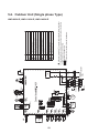
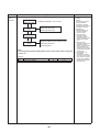
5-2. Outdoor Unit (Single phase Type)
HWS-803H-E, HWS-1103H-E, HWS-1403H-E
5-3. Outdoor Unit (3 phase type)
HWS-1103H8(R)-E, -1403H8(R)-E, -1603H8(R)-E
P.C. board
MCC-1596
P.C. board
MCC-1597
(1103H8R-E
1403H8R-E
1603H8R-E)
only
Hydro
unit
indicates the teminal block. Alphanumeric characters
in the cycle indicate terminal No.
The two-dot chain line indicates the wiring procured locally.
indicates the P.C. board.
For the hydro unit circuit, refer to the wiring diagram of
the indoor unit.
24
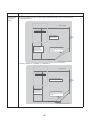
5-4. Hot Water Cylinder Unit
Blue
Green /
Yellow
Double pole thermal cut out
Blue
Brown
Brown
1 2
TB03(230V)
A B
TB06(TTW)
TTW sensor
Hot water cylinder heater
Supply 220 - 230 V from hydro unit
Cable size 1.5 mm2 (minimum)
To hydro unit
25
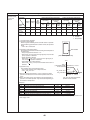
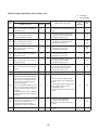
6
Key Electric Component Rating
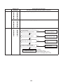
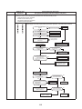
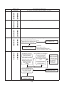
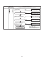
6-1. Hydro Unit
HWS-803XWHM3-E, T6-E, D6-E, T9-E
Model name
No.
Component name
Type name
Rating
M3-E T6-E D6-E T9-E
1
2
Circulating pump
Backup heater 6 kW
O
O
O
O
O
O
O
UPS025-65 K 130
AC230 V 0.54 A (MAX)
–
AC 400 V (3N) 6 kW (AC230 V 3 kW
compatible)
O
–
AC400V (3N) 9 kW
3
Backup heater 9 kW
4
Water heat exchange
temperature sensor
(TC sensor)
O
O
O
O
–
5
Water inlet temperature sensor
(TWI sensor)
O
O
O
O
–
6
Water outlet temperature sensor
(TWO sensor)
O
O
O
O
–
7
Heater outlet water temperature
sensor
(THO sensor)
O
O
O
O
–
8
Floor inlet temperature sensor
(TFI sensor)
O
O
O
O
–
O
O
O
O
–
Operating pressure 4.15 MPa +0 -0.3
MPa
O
O
O
O
–
Operating pressure 0.20 MPa
O
O
O
O
–
Operating temperature 75±3°C DC42 V
/ 0.2 A
9
10
11
Pressure switch
Low pressure sensor
Bimetal thermostat (auto)
10 k: (25°C)
10 k: (25°C)
10 k: (25°C)
10 k: (25°C)
10 k: (25°C)
12
Bimetal thermostat (single
operation)
O
O
O
O
–
Operating temperature 95±5°C
AC250 V / 16 A
13
Flow switch
O
O
O
O
–
Operating flowing quantity 13
14
Output board (OP)
OP
OP
OP
OP
TCB-PCIN3E
AC230 V 0.5 A DC24 V 1 A
15
Input board (OP)
OP
OP
OP
OP
TCB-PCM03E
Contact input
16
Remote control (Main)
O
O
O
O
HWS-AMS11E
17
Remote control (Sub)
OP
OP
OP
OP
HWS-AMS11E
O
O
O
O
–
AC230 V 0.1 A
2Wire, 3Wire SPST, SPDT type
mountable
O
O
O
O
–
AC230 V 0.1 A 2Wire type mountable
O
O
O
O
–
AC230 V 0.1 A
3Wire SPST, SPDT type mountable
Water 3-way valve terminal
18
19
20
Water 2-way valve terminal
Mixing valve terminal
21
Circulating pump terminal
O
O
O
O
–
AC230 V 1.0 A
22
Booster heater terminal
O
O
O
O
–
AC230 V 1.0 A
23
Fuse
O
O
O
O
–
AC 250 V 30 A
O ········· Applied
OP······· Optional accessory
26
/min
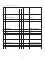
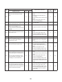
HWS-1403XWHM3-E, T6-E, D6-E, T9-E
Model name
No.
Component name
Type name
Rating
M3-E T6-E D6-E T9-E
1
2
Circulating pump
Backup heater 6 kW
O
O
O
O
O
O
O
UPS25-80 130
AC230 V 0.83 A (MAX)
–
AC 400 V (3N) 6 kW (AC230 V 3kW
compatible)
O
–
AC 400 V (3N) 9 kW
3
Backup heater 9 kW
4
Water heat exchange
temperature sensor
(TC sensor)
O
O
O
O
–
5
Water inlet temperature sensor
(TWI sensor)
O
O
O
O
–
6
Water outlet temperature sensor
(TWO sensor)
O
O
O
O
–
7
Heater outlet water temperature
sensor
(THO sensor)
O
O
O
O
–
8
Floor inlet temperature sensor
(TFI sensor)
O
O
O
O
–
O
O
O
O
–
Operating pressure 4.15 MPa +0 -0.3
MPa
O
O
O
O
–
Operating pressure 0.20 MPa
O
O
O
O
–
Operating temperature 75±3°C DC42 V
/ 0.2 A
9
10
11
Pressure switch
Low pressure sensor
Thermal protector (auto)
10 k: (25°C)
10 k: (25°C)
10 k: (25°C)
10 k: (25°C)
10 k: (25°C)
12
Thermal protector (single
operation)
O
O
O
O
–
Operating temperature 95±5°C AC250
V 16 A
13
Flow switch
O
O
O
O
–
Operating flowing quantity 17.5 L/min
14
Output board (OP)
OP
OP
OP
OP
TCB-PCIN3E
AC230 V 0.5 A DC24 V 1 A
15
Input board (OP)
OP
OP
OP
OP
TCB-PCM03E
Contact input
16
Remote control (Main)
O
O
O
O
HWS-AMS11E
17
Remote control (Sub)
OP
OP
OP
OP
HWS-AMS11E
O
O
O
O
–
AC230 V 0.1 A
2Wire, 3Wire SPST, SPDT type
mountable
O
O
O
O
–
AC230 V 0.1 A 2Wire type mountable
O
O
O
O
–
AC230 V 0.1 A
3Wire SPST, SPDT type mountable
Water 3-way valve terminal
18
19
20
Water 2-way valve terminal
Mixing valve terminal
21
Circulating pump terminal
O
O
O
O
–
AC230 V 1.0 A
22
Booster heater terminal
O
O
O
O
–
AC230 V 1.0 A
23
Fuse
O
O
O
O
–
AC 250 V 30 A
O ········· Applied
OP······· Optional accessory
27
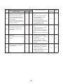
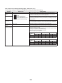
6-2. Outdoor Unit
HWS-803H-E
No.
Component name
Type name
Rating
1
Compressor
DA220A2F-22L
2
Outdoor fan motor
ICF-280-A60-1
Output 60 W
4-way valve coil
VHV-01AP552B1
AC220 - 230 full-wave rectifier input, alive time
10 sec or less
4
Pulse motor valve (PMV) coil
CAM-MD12TF-15
DC12 V
5
Compressor case thermostat
US-622KXTMQO-SS
OFF: 125±4°C ON: 90±5°C
6
Reactor
CH-56
5.8 mH, 18.5 A
PC board
MCC-1571
Input 1Ø, AC220 - 230 V ± 10 %,
50/60 Hz
3
7
28
HWS-1103H-E, 1403H-E
No.
Component name
Type name
Rating
1
Compressor
DA422A3F-25M
2
Outdoor fan motor (x2)
ICF-280-A100-1
Output 100 W
3
Reactor (x2)
CH-44
1.4 mH, 25 A
4
4-way valve coil
5
Pulse motor valve (PMV) coil
UKV-A038
DC12 V
6
Board
MCC-1560
Input 3Ø, AC230 V±23 V, 50/60 Hz
7
Compressor case thermostat
US-622KXTMQO-SS
OFF = 125 ± 4 °C, ON = 90 ± 5 °C
8
PC board
MCC-1571
Input 1Ø, AC220 - 230 V ± 10 %, 50/60 Hz
AC220 - 230 V full-wave rectifier input, alive time 10 sec or less
29
HWS-1103H8(R)-E, 1403H8(R)-E, 1603H8(R)-E
No.
Component name
Type name
Rating
1
Compressor
DA422A3F-27M
2
Outdoor fan motor (x2)
ICF-280-A100-1
Output 100 W
3
Reactor
CH-78
4.2 mH, 16 A
4
Reactor
CH-68
18 mH, 5 A
5
4-way valve coil
STF-01A5502E1
AC220 - 230 V
6
Pulse motor valve (PMV) coil
UKV-A038
DC12 V
7
PC board (Compressor)
MCC-1596
8
PC board (Fan motor drive)
MCC-1597
9
PC board (Control)
MCC-1599
10
PC board (Noise filter)
MCC-1600
11
High pressure switch
ACB-4UB83W
OFF = 4.15 +0, -0.3 Mpa
12
Compressor case thermostat
US-622
OFF = 125 ± 4 °C, ON = 90 ± 5 °C
13
Relay
EL200/240 A2-F()
Contact = AC480V, 20 A
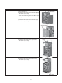
30
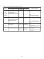
6-3. Hot Water Cylinder Unit
Model name
No.
Component name
1501
CSH
M3-E
(-UK)
2101
CSH
M3-E
(-UK)
3001
CSH
M3-E
(-UK)
Type name
1
Hot water cylinder heater
O
O
O
–
2
Hot water cylinder temperature
sensor
(TTW sensor)
O
O
O
–
O
O
O
–
3
Thermal cut-out
Rating
AC230 V 2.75 KW
10 k: (25°C)
O ········· Applied
31
Operating temperature
Manual reset 82°C (+3k/-2k)
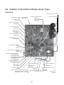
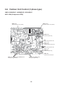
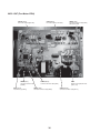
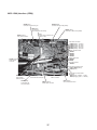
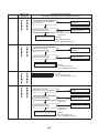
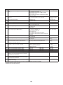
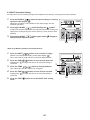
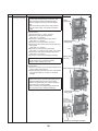
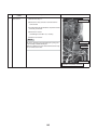
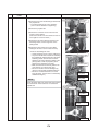
6-4. Water Heat Exchange Control Board
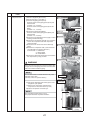
HWS-803XWHM3-E, 803XWHT6-E, 803XWHD6-E, 803XWHT9-E
HWS-1403XWHM3-E, 1403XWHT6-E, 1403XWHD6-E, 1403XWHT9-E
Relay board connector
CN501
TC sensor connector
TTW sensor connector
CN203
CN214
Low pressure sensor connector
Remote control
TFI sensor
CN207, CN212
connector
connector
CN41
CN213
THO sensor connector
CN206
TWI sensor connector
CN204
TWO sensor connector
CN205
Pressure switch connector
CN201
Overheat protection thermostat
input connector
CN202
Flow switch connector
CN200
Option board
connector
CN208-CN211
Transformer connector
CN102
Built-in pump
connector
CN603
Transformer input connector
CN101
Hot water cylinder
drive connector
CN601
AC power supply connector
CN100
3WV drive connector
CN602
Mixing valve drive
connector
CN604
Backup heater 1 drive
connector
CN605
Serial input connector
CN305
Backup heater 2 drive connector
CN606
32
6-5. Outdoor Control Board (Single phase Type)
HWS-803H-E
Reactor connection connector
Power circuit protection
fuse
F100 (250 V, 3.15 A,
plastic case)
Fan motor output
CN300 (White)
Compressor output terminals
CN202
CN201
CN200
Electrolytic capacitors
Case thermostat connector
CN609(Blue)
4-way valve connector
CN701(White)
Compressor ON
output connector
CN704(Blue)
Heater output connector
CN703(Grey)
External input connector
CN610(Yellow)
Special operation switches
SW801
SW804
Display change-over switches
SW800
SW803
Temperature sensor connectors
TL CN604(White)
TD CN603(White)
TO CN602(Yellow)
TE CN601(White)
TS CN600(White)
Alive, error display LEDs
D800 804(Yellow)
D805(Green)
PMV connector
CN710 (White)
4-way valve protection
fuse
F700 (250 V, 3.15 A,
plastic case)
Initialization switch
SW802
Power circuit protection
fuse
F01 (250V, 25A)
Power supply connection lead
Connecting cable connector
wires
CN04(White)
P01(Red)
Hydro-outdoor communication signal LEDs
D503 (Green, Outdoor => Hydro) Connecting cable protection fuse P02(White)
Earth lead wire
F03 (250 V, 10 A)
D502 (Amber, Hydro => Outdoor)
P09 (Black)
33
HWS-1103H-E, 1403H-E
Fan motor output (Lower)
CN300(White)
Fan motor output (Upper)
CN400(White)
Compressor output terminals
CN202
CN201
CN200
Electrolytic capacitors
Case thermostat connector
CN609(Blue)
Power circuit protection
fuse
F100(250V,3.15A,
plastic case)
4-way valve connector
CN701(White)
Compressor ON output
connector
CN704(Blue)
Heator output
connector
CN703(Grey)
External input connector
CN610(Yellow)
Special operation switches
SW801
SW804
Display change-over
switches
SW800
SW803
Temperature sensor
connectors
TL CN604(White)
TD CN603(White)
TO CN602(Yellow)
TE CN601(White)
TS CN600(White)
Alive, abnormal display LEDs
D800 804(Yellow)
D805(Green)
Power supply connection
lead wires
P01(Red)
P02(White)
P03(Black)
PMV connector
CN710(White)
Initialization switch
SW802
4-way valve protection fuse
F700(250V,3.15A
plastic case)
Connecting cable connector
Hydro-outdoor communication CN04(White)
signal LEDs
D503 (Green, Outdoor =>Hydro)
Connecting cable protection fuse
D502 (Amber, Hydro => Outdoor)
F03(250V,10A)
34
Earth lead wire
P09(Black)
Power supply protection fuses
F01
(250V,25A)
6-6. Outdoor Unit Control (3 phase type)
HWS-1103H8(R)-E, 1403H8(R)-E, 1603H8(R)-E
MCC-1596 (Compressor IPDU)
CN851 (Red)
CN101 (White)
Connector for MCC-1597 (CN502)
Connector for MCC-1597 (CN505)
CN13 (Black)
Terminal for power relay
F02
Electric circuit protective fuse
(500V, 31.5A)
CN12 (White)
Terminal for MCC-1600 (CN17)
F01
Electric circuit protective fuse
(500V, 31.5A)
CN11 (Red)
Terminal for power relay
CN04 (Red)
Terminal for PTC thermistor
CN211 (Red), CN212 (White), CN213 (Black)
CN19 (Yellow), CN20 (Yellow)
Compressor output terminal
Terminal for reactor CH78
35
MCC-1597 (Fan Motor IPDU)
CN750 (White)
Fan motor output (Upper side)
CN504 (Blue)
Connector for MCC-1599
(CN802)
CN700 (Blue)
CN500 (Red)
Fan motor output (Lower side)
Connector for MCC-1600 (CN23)
and reactor CH68
CN602 (Black)
Connector for MCC-1600 (CN51)
F500
Electric circuit protective fuse
(250V, 15A)
P501 (Black)
CN505 (Red)
CN502 (White)
Lead wire for grounding
Connector for MCC-1596 (CN851)
Connector for MCC-1596 (CN101)
36
MCC-1599 (Interface (CDB))
CN708 (Blue)
CN608 (White)
Connector for MCC-1600 (CN50)
Connector for power relay coil
CN02 (Red)
CN802 (White)
Connector for MCC-1597 (CN504)
Connector for
MCC-1600 (CN10 and CN19)
F01
CN700 (Yellow)
4-way valve connector
Power supply protective fuse
(250V, 3.15A)
Temp.sensor connector
CN604 (White) TL sensor
CN603 (White) TD sensor
CN602 (Yellow) TO sensor
CN601 (White) TE sensor
CN600 (White) TS sensor
Specific operation switch
SW801
SW804
SW805
SW806
Display select switch
SW800
SW803
CN703 (Gray)
Heater output
connector
Initial setting switch
SW802
Power-ON,error display LED
D800 to D804 (Yellow)
D805 (Green)
CN690 (Green)
High-pressure
switch connector
CN704 (Blue)
Compressor ON
out put connector
CN609 (Blue)
Case thermostat connector
CN710 (White)
PMV1 Connector
Hydro/Outdoor communication
signal LED
D503 (Green), (Outdoor → Hydro)
D502 (Orange), (Hydro → Outdoor)
CN01 (White)
CN610 (Yellow)
Outside input connector
37
Inter-unit cable connector
MCC-1600 (Noise Filter)
CN05 (Red)
Power supply terminal (L1)
CN10 (Red)
Terminal for MCC-1599 (CN02) and Terminal for PTC thermistor
CN16 (Red)
Terminal for power relay
F01
Varistor protective fuse
(250V, 6.3A)
CN06 (White)
Power supply terminal (L2)
CN17 (White)
Terminal for
F02
Varistor protective fuse
MCC-1596 (CN02)
(250V, 6.3A)
CN18 (Black)
Terminal for
power relay
CN07 (Black)
Power supply terminal (L3)
CN19 (Gray)
Terminal for
MCC-1599 (CN02)
F03
Varistor protective fuse
CN09 (Brown)
Terminal for
(250V, 6.3A)
grounding
CN20 (White)
Power supply terminal (L2)
CN23 (Red)
Connector for
MCC-1597 (CN500)
CN08 (Gray)
Neutral terminal
CN51 (Black)
Connector for
CN50 (White)
Connector for
MCC-1597 (CN602)
MCC-1599 (CN608)
38
39
Outdoor unit
8~16kW
(Single phase)
(3 place)
TC
Backup heater
Ø1 : 3kW
Ø3 : 6kW
Ø3 : 9kW
Local hot water system
3.5bar
Reducing
valve(UK)
Pressure relief
Set value : 7bar(UK)
Water heat exchanger
max : 10bar
TWO
Thermal protector
Single operation
set : 95 ± 5°C
Air vent valve
Water inlet
Thermal cut-out
(manual reset)
82°C (+3k/-2k)
Water outlet
TWI
TTW
AC pump
max : 10bar
Hot water cylinder
Water vent
valve
Flow sw
Menometer
gage : - 6bar
Thermal protector
(auto)
set : 75 ± 3°C
THO
Booster heater
(local)
Cylinder heater
Ø1 : 2.75kW
Relief valve(UK)
90°C
10 bar
Drain cock for water charge
(locally procured)
40 mesh
Safety valve
set : 3.5bar
Motorized 3-way valve
(locally procured)
AC230V
Strainer
(locally procured)
M
Low pressure sensor
Pressure switch
4.15MPa
Expansion vessel
set : 1bar
Pressure relief valve
set : 3bar
Boiler
(local)
Floor
heating
zone2
TFI
AC pump
(locally procured)
2-way valve for
cooling mode
(locally procured)
AC230V
zone1
Buffer tank(locally procured)
Moterized mixing valve
(locally procured)
AC230V
By-pass valve
(locally procured)
Radiator unit
By-pass valve
(locally procured)
Fan coil unit
7
Refrigeration Cycle / Water System Diagram
7-1. Water System Diagram
M
Installation example of water circuit
(1)
(2)
(3)
(4)
(5)
(6)
The water flowing for a system without buffer tank ((1), (2), (3), (5)) requires17.5 /min (803XWH 13.0 /min) or
more. This water flowing requires 5 or more branches of Floor heating or Radiator etc.
Less than 5 branches may cause a flow deficiency. In this case, please provide a buffer tank and secondary pumps
as shown in (4).
Please check how to install the boiler (See page 52)
40
7-2. Refrigeration Cycle System Diagram
HWS-803XWHM3-E, HWS-803XWHT6-E, HWS-803XWHD6-E, HWS-803XWHT9-E/HWS803H-E
Outdoor unit
Hydro unit
Heating / Hot-water supply
Defrosting / Cooling
Low
pressure
sensor
Expansion vessel
Manometer
TWO
Water vent valve
Air vent valve
TD
Compressor
(DA220A2F-22L)
Pressure switch
Backup heater
Plate-type
water heat
exchanger
Safety valve
4-way valve
(STF-218G)
TS
TO
Outdoor heat
exchanger
Pulse motor valve
(CAM-B30YGTF-2)
Circulating pump
(UPS025-65 K 130)
THO
TC
P
TWI
TE
Flow switch
(VH-8706)
Accumulator
(1800 cc)
Refrigerant R410A ... 1.8 kg
HWS-1403XWHM3-E, HWS-1403XWHT6-E, HWS-1403XWHD6-E, HWS-1403XWHT9-E/
HWS-1103H-E, HWS-1403H-E
Outdoor unit
Hydro unit
Heating / Hot-water supply
Defrosting / Cooling
Low
pressure
sensor
Expansion vessel
Manometer
TWO
Water vent valve
Air vent valve
TD
Compressor
(DA422A3F-25M)
Pressure switch
Backup heater
Plate-type
water heat
exchanger
Safety valve
4-way valve
(STF-0401G)
TS
TO
Outdoor heat
exchanger
Pulse motor valve
(UKV-25D100)
Circulating pump
(UPS25-80 130)
THO
TC
TE
TWI
P
Flow switch
(VH-8705)
Accumulator
(2500 cc)
41
HWS-1403XWHM3-E, HWS-1403XWHT6-E, HWS-1403XWHD6-E, HWS-1403XWHT9-E/
HWS-1103H8(R)-E, HWS-1403H8(R)-E, HWS-1603H8(R)-E
Outdoor unit
Hydro unit
Heating / Hot-water supply
Defrosting / Cooling
Muffler
Ø25 x L210
Ø25 x L180
Low
pressure
sensor
Expansion vessel
Manometer
Pressure switch
TWO
Water vent valve
Air vent valve
TD
Compressor
(DA422A3F-27M)
Pressure switch
Backup heater
Plate-type
water heat
exchanger
Safety valve
4-way valve
(STF-0401G)
TS
TO
Outdoor heat
exchanger
Pulse motor valve
(UKV-25D100)
Circulating pump
(UPS25-80 130)
THO
TC
TE
TWI
P
Flow switch
(VH-8705)
Accumulator
(2500 cc)
42
8
Operational Description
This chapter describes the working circuit and control of Air to Water Heat Pump about the following operations.
Item
Page
8-1
8-1. Basic Operation
1) Operation control
2) Hot water supply operation
3) Heating operation
4) Cooling operation
44 to 46
8-2
8-2. Operation Mode and Control Method
1) Heat pump operation range of hot water supply, heating and cooling
2) Hot water supply operation
3) Heating operation
4) Cooling operation
5) Simultaneous operations of "hot water supply" and "heating"
6) Simultaneous operations of "hot water supply" and "cooling"
7) Boiler control
8) Hot water boost operation
9) Anti bacteria (ANTI BACTERIA) operation
10) Night set back (NIGHT SET BACK) operation
11) FROST PROTECTION operation
12) AUTO operation
13) Night time low-noise operation
47 to 57
8-3
8-3. Hydro Unit Control
1) Capacity control (compressor, high-temperature release, low-temperature release)
2) Heater control
3) Circulation pump control
4) Control by the flow switch
5) Mixing Valve control (2-temperature heating control)
6) Room temperature control
7) Room temperature control with the thermostat
8) Control of force stop and restart
9) Control of limit of heat pump operation
10)Output signal control 1
11)Output signal control 2
12) Q-H characteristics of hydro unit
13) Automatic restart control
14) Piping freeze prevention control
15) High return water protect control.
58 to 71
8-4
8-4. Outdoor unit control
1) PMV (Pulse motor valve) control
2) Discharge temperature release control
3) Current release control
4) Current releases shift control
5) Outdoor fan control
6) Defrosting control
7) Winding heating control
8) Short circuit operation prevention control
9) Over current protection control
10) High pressure release control
11) High pressure switch
12) Compressor case thermostat
13) Bottom plate heater control
72 to 80
43
Item
8-1.
Basic
Operation
Operation flow and applicable data, etc.
Operation description
1) Operation control
Remote controller
Operation
condition selection
Heating: Run/Stop
Remote control settings
<Heating> Temperature setting
<Hot water supply > Temperature setting
<Cooling> Temperature setting
Hot water supply: Run/Stop
Cooling: Run/Stop
Serial signals transmit
and receive
Auto Temp
Anti Bacteria
Frost protection
Hot waterboost
AC 230 V for Hot water cylinder heater
AC 400 V (3N~) for Back up heater
Hydro
unit
Thermostat (Cooling/Heating)
Serial signals
transmit and receive
Forcible stop input
Water heat
exchange
Sub board
2WV_W
3WV_W
Hot water supply
heater MG
Mixing Valve
Pressure switch
Lo pressure sensor
Water heat
exchange
control board
Serial signals
transmit and receive
Error Alarm stop output
Defrosting output
Operation output
Boiler "ON/OFF"
Booster Heater
Condensed temperature sensor (TC)
Water inlet temperature sensor (TWI)
Water outlet temperature sensor (TWO)
Water heater outlet temperature sensor (THO)
Hot water cylinder sensor (TTW)
Floor inlet sensor (TFI)
Overheat prevention thermostat
Flow switch
Hot water cylinder heater
Backup heater 1 power-relay
Backup heater 2 power-relay
AC pump 1 (Built-in pump)
Outdoor
unit
Serial
communication
Serial signals
transmit and receive
Outdoor
unit control
AC 220 - 230 V for heat pump (Single phase type)
AC 380 - 400V for heat pump (3 phase type)
Outdoor unit contro
Inverter
Inverter frequency control
Waveform synthesis function
Compressor
Outdoor fan motor
Calculation function (Temperature calculation)
AD conversion function
Rapid heating function
Compressor restart
Delay function
G-Tr overcurrent prevention function
Defrosting operation function
Td sensor
Ts sensor
Te sensor
To sensor
PMV
4-way valve
High pressure switch (3 phase type only)
44
1. Purpose
The operations of the
hydro unit and the
outdoor unit are
controlled according to
user-defined operation
condition settings.
2. Details
The operation controls
include those shown on
the left.
3. Operations
1) An operation condition
is selected with the
remote controller.
2) Setting the remote
controller button to
“ON” transmits a signal
to the hydro unit.
3) The hydro unit
controller controls the
operations shown on
the left while also
controlling the water 2way valve, water 3-way
valve, circulation
pump, mixing valve,
hot water cylinder
heater, and backup
heater.
4) The hydro unit
controller transmits an
operation instruction to
the outdoor unit, and
uses serial signals to
transmit and receive
control statuses.
5) The outdoor unit
control unit performs
the operation controls
shown on the left while
also controlling the
compressor, outdoor
fan motor, pulse motor
valve, and 4-way valve.
Item
8-1.
Basic
Operation
Operation flow and applicable data, etc.
Operation description
2) Hot water supply operation
[HOT WATER]
button set to "ON"
Hot water temperature: 40°C to 75°C
Circulation pump "ON/OFF" control
Water 3-way valve control
Hot water cylinder heater control
Hydro unit
control
Operation instruction
signal transmit
Number of compressor revolutions control
Number of outdoor fan motor revolutions control
Pulse motor valve control
4-way valve control
Outdoor unit
control
3) Heating operation
ZONE1, 2
button set to "ON"
Heating temperature: 20°C to 55°C
Circulation pump "ON/OFF" control
Water 3-way valve control
Water 2-way valve control
Mixing Valve control
Backup heater control
Booster heater control
Hydro unit
control
Operation instruction
signal transmit
Number of compressor revolutions control
Number of outdoor fan motor revolutions control
Pulse motor valve control
4-way valve control
Outdoor unit
control
Set temperature
(TSC_F)
[°C]
A(40)
B(35)
C(30)
D(25)
E(20)
-20
T1
0
T3
20
A, B, C, D, E Setting available range 20 to 55°C
T1 Setting available range
-15 to 0°C
T3 Setting available range
0 to +15°C
45
Hot water supply operation
1. Purpose
Hot water supply
2. Details
This section performs
hot water supply
operation according to
heating conditions
specified for the steps
on the left.
3. Operations
1) Set the [HOT WATER]
remote controller
button to “ON”.
2) The hydro unit
controller starts to
transmit a hot water
supply operation signal
to the outdoor unit
control unit.
3) The hydro unit
performs the operation
controls shown on the
left while also
controlling the
circulation pump, hot
water cylinder heater
“3WV”.
4) The outdoor unit
controls the
compressor, outdoor
fan motor, electric
expansion valve, and
4-way valve based on
the operation signals
transmitted by the
hydro unit.
Heating operation
1. Purpose
Heating
2. Details
This section performs
heating operation
according to heating
conditions specified for
the steps on the left.
3. Operations
1) Set the [ZONE1, 2]
remote controller
button to “ON”.
2) The hydro unit
controller starts to
transmit a heating
operation signal to the
outdoor control unit.
3) The hydro unit
performs the operation
controls shown on the
left while also
controlling the
circulation pump,
backup booster heater
“ON/OFF”, water 2way valve, and water 3way valve.
4) The outdoor unit
controls the
compressor, outdoor
fan motor, electric
expansion valve, and
4-way valve based on
the operation signals
transmitted by the
hydro unit.
Item
8-1.
Basic
Operation
Operation flow and applicable data, etc.
Operation description
1. Purpose
Cooling
2. Details
ZONE1, 2
Cooling temperature: 10°C to 25°C
This section performs
button set to "ON"
cooling operation
according to cooling
conditions specified for
Circulation pump "ON/OFF" control
the steps on the left.
Hydro unit
Water 3-way valve control
3. Operations
control
Water 2-way valve control
1) Set the [ZONE1, 2]
remote controller
button to “ON”.
2) The hydro unit
Operation instruction
controller starts to
signal transmit
transmit a cooling
operation signal to the
outdoor unit control
Number of compressor revolutions control
unit.
Number of outdoor fan motor revolutions control
Outdoor unit
3) The hydro unit
controller performs the
Pulse motor valve control
control
operation controls
4-way valve control
shown on the left while
also controlling the
circulation pump, water
2-way valve, and water
NOTE:
3-way valve.
No coding mode in default setting. When use the cooling mode, please change the
4) The outdoor unit
FC02 to “0”.
controls the
compressor, outdoor
fan motor, pulse motor
Related FC
valve, and 4-way valve
based on the operation
FC No.
Setting item
Default
Setting available range
signals transmitted by
02
Cooling mode availability
1: No
0: Yes
the hydro unit.
4) Cooling operation
46
Item
8-2.
Operation Mode
and Control
Method
Operation flow and applicable data, etc.
1) Heat pump operation range of hot water supply, heating and cooling
The heat pump operation range of hot water supply, heating and cooling is shown on the figures below.
1) HWS-803XWH**-E
TO
43
42
41
40
39
38
37
36
35
34
33
32
31
30
29
28
27
26
25
24
23
22
21
20
19
18
17
16
15
14
13
12
11
10
9
8
7
6
5
4
3
2
1
0
-1
-2
-3
-4
-5
-6
-7
-8
-9
-10
-11
-12
-13
-14
-15
-16
-17
-18
-19
-20
Heater for heating
Cooling operation range
Heat pump operation
range of how water
supply and heating.
Heat pump operation
range of how water
supply and heating
Freeze determination
is executed only once.
Heating
thermostat
OFF
(Conditional operation range)
Start condition: The compressor
stops for less than 2 hours and
TD>50°C.
Heater for heating
5
6
7
8
9
10 11 12 13 14 15 16 17 18 19 20 21 22 23 24 25 26 27 28 29 30 31 32 33 34 35 36 37 38 39 40 41 42 43 44 45 46 47 48 49 50
Water temperature at inlet (TWI)
2) HWS-1103XWH**-E, 1403XWH**-E, 1603XWH**-E
TO
43
42
41
40
39
38
37
36
35
34
33
32
31
30
29
28
27
26
25
24
23
22
21
20
19
18
17
16
15
14
13
12
11
10
9
8
7
6
5
4
3
2
1
0
-1
-2
-3
-4
-5
-6
-7
-8
-9
-10
-11
-12
-13
-14
-15
-16
-17
-18
-19
-20
Heater for heating
Cooling operation range
Heat pump operation range of
how water supply and heating
Heat pump operation
range of how water
supply and heating
Freeze determination
is executed only once.
(Conditional operation range)
Start condition: The compressor
stops for less than 2 hours and
TD>40°C.
Heater for heating
5
6
7
8
9
10 11 12 13 14 15 16 17 18 19 20 21 22 23 24 25 26 27 28 29 30 31 32 33 34 35 36 37 38 39 40 41 42 43 44 45 46 47 48 49 50
Water temperature at inlet (TWI)
47
Heating
thermostat
OFF
Item
8-2.
Operation Mode
and Control
Method
Operation flow and applicable data, etc.
The following shows the operation modes and controlled objects.
Operation
mode
Heating and Hot water both operate
Cooling
only
Heating
only
Hot
water
supply
only
Controlled
object
Heat pump select
for heating
Heat pump select
for hot water
supply
Cooling and Hot water both operate
Heat pump select
for hot water
supply
Heat pump select
for cooling
Heating
side
Hot
water
supply
side
Heating
side
Hot
water
supply
side
Cooling
side
Hot
water
supply
side
Cooling
side
Hot
water
supply
side
Heat pump
O
O
O
O
×
×
O
O
×
×
O
Backup
heater
×
O
×
O
×
×
×
×
×
×
×
Hot water
cylinder
heater
×
×
O
×
O
×
O
×
O
×
O
O Possible
× Not possible
2) Hot water supply operation
1) Operation start condition
When the [HOT WATER] remote controller button is pressed
and the following operation start condition is met, the operation
starts.
• TTW < 38°C is detected.
2) Operation mode determination
An operation mode is determined according to the temperature
of TTW sensor.
• Heat pump operation selection *1 *2
• When TTW < 38°C (a zone in the right figure) is met, the heat
pump operation is selected.
• Heater operation selection
When 45°C TTW < TSC_H (b zone in the right figure) is
met, the heater operation is selected.
• Thermostat status "OFF" selection
When TTW TSC_H is met, the thermostat status "OFF" is
selected.
3) Operation stop
The operation stops in the following cases.
• The remote controller gives a stop instruction.
• TTW TSC_H is met.
TTW sensor
(Hot water cylinder unit)
TTW
TSC_H
(Temperature set with Thermostat OFF c Zone
remote controller)
Heater operation
HP_H OFF 45°C
HP_H ON 38°C
*1: When the outside temperature is -20°C or below, the heater
operation is selected even if the TTW temperature falls into "a
zone".
*2: When "Hot water supply" and "Heating" are simultaneously in
operation, the heater operation may be selected depending on
the outside air temperature.
b Zone
Heat pump
operation
a Zone
TSC_H is hot water temperature
set with remote controller
Related FC
FC No.
Default
Setting available range
1E
Upper limit of hot water supply temperature
Setting item
75°C
60-80°C
1F
Lower limit of hot water supply temperature
40°C
40-60°C
20
Heat pump start temperature
38°C
20-45°C
21
Heat pump end temperature
45°C
40-50°C
24
Outside air correction start temperature for hot water supply*3
0°C
-20-10°C
25
Outside air correction temperature for hot water supply*3
3 degree
0 -15 degree
*3:When the outside temperature is 0°C or below, the boil-up temperature will be higher that setting temperature in hot
water supply mode.
48
Item
8-2.
Operation Mode
and Control
Method
Operation flow and applicable data, etc.
3) Heating operation
<Operation only for ZONE1>
• This operation is enabled when DP_SW12_2 ZONE1 is set to "OFF" (default).
• The remote controller displays
settings, and only the set temperature of
can be changed.
<Operation for ZONE1 and ZONE2 (2 temperatures control)>
• This operation is enabled when DP_SW12_2 ZONE1 is set to "OFF" (default) and DP_SW12_3 ZONE2 to "ON".
• The remote controller displays
settings, and the set temperatures of
can be changed.
• To set temperatures for
and
, use SELECT
to switch between
and
.
• For 2 zone temperatures control, the flow adjustment of MIXING VALVE controls the water temperature of
. For details,
see the description on MIXING VALVE control in 8-3-5.
1) Operation start condition
Pressing the [ZONE1, 2] button of remote controller starts a
heating operation. *1 *2
2) Operation mode selection
An operation mode is determined according to the temperature
of TWI sensor.
• Heat pump operation selection *1 *2
When TWI < TSC_F (d zone in the right figure) is met, the
heat pump operation is selected.
• Thermostat status "OFF"
When TWI TSC_F (e zone in the right figure) is met, the
thermostat status "OFF" is selected.
TWI
Thermostat off
operation
e zone
TSC_F
diff2K
d zone
Heat pump operation
TSC_F is a heating temperature
set with remote controller
3) Operation stop condition
When the following condition is met, the heating operation
stops.
• The remote controller gives a stop instruction.
*1: When the outside temperature is -20°C or below, the heater
operation is selected even if the TWI temperature falls into "d
zone".
*2: When "Hot water supply" and "Heating" are simultaneously in
operation, the heater operation may be selected depending on
the outside air temperature.
Related FC
FC No.
Default
Setting available range
1A
Upper limit of heating (Zone1) limited temperature
Setting item
55
37-55°C
1B
Lower limit of heating (Zone1) limited temperature
20
20-37°C
1C
Upper limit of heating (Zone2) limited temperature
55
37-55°C
1D
Lower limit of heating (Zone2) limited temperature
20
20-37°C
49
Item
8-2.
Operation Mode
and Control
Method
Operation flow and applicable data, etc.
4) Cooling operation
Pressing the [ZONE1, 2] button and then [OPERATION MODE] starts a cooling operation.
1) Operation start condition
Pressing the [ZONE1, 2] button and then [OPERATION
MODE] starts a cooling operation.
TWI
Heat pump operation
(cooling)
TSC_F
(Temperature set with
2) Operation mode selection
An operation mode is determined according to the
temperature of TWI sensor.
d zone
Diff : 2k
remote controller)
e zone
TSC_F
Thermostat off operation
• Heat pump operation selection *1
When TWI
TSC_F (d zone in the right figure) is met, the
heat pump operation is selected.
• Thermostat status "OFF"
When TWI < TSC_F (e zone in the right figure) is met, the
thermostat status "OFF" is selected.
TSC is a cooling temperature
set with the remote controller
3) Operation stop condition
When either of the following conditions is met, the cooling
operation stops.
• The remote controller gives a stop instruction.
• The operation is switched to heating.
*1: When the outside temperature is 10°C or below, cooling does
not start even if the TWI temperature falls into "d zone".
Related FC
FC No.
Setting item
Default
Setting available range
1: Not permit
0: Permitted
Upper limit of cooling setting temperature
25
20-30°C
Lower limit of cooling setting temperature
10
10-20°C
02
Cooling mode availability
18
19
5) Simultaneous operations of "hot water supply" and "heating"
At the time of "Hot water supply" and "Heating" simultaneous
operation, the operation mode is select as follows depending on
the outside air temperature.
• f zone Operation with hot water supply priority
A heat pump operation is performed in the hot water supply
side, and a heating operation in the heating side.
• g zone Operation with heating priority
A heat pump operation is performed in the heating side, and
a cylinder heater operation in the hot water supply side.
TO
Hot water
supply heat
pump priority
operation
0
(FC22) Heating heat
pump priority
operation
-20
Heater operation
f zone
Diff : 5deg
g zone
Diff : 5deg
h zone *3
Operation mode by zone
Zone
Hot water supply side
f
Heat pump *2
Heating side
Stop *2
g
Heater
Heat pump
h
Heater *3
Heater *3
*2: Note that after a heat pump operation for "Hot water supply" is selected in f zone, when the operation moves to a
heater operation for "hot water" and then 5 minutes has passed (Hot water supply operation in b zone), the operation
mode changes as follows.
Zone
Hot water supply side
Heating side
f'
Heater
Heat pump
When TTW
45°C (FC: changeable) is met, the operation ends f' zone and returns to f zone.
*3: If the h-zone operation starts while external temperature is higher than -20°C, the h-zone operation continues for 60
minutes.
50
Item
Operation flow and applicable data, etc.
Related FC
FC No.
*
8-2.
Operation Mode
and Control
Method
Setting item
07
Maximum HP operation time for hot water heater, when “hot
water supply” + “heating mode” both operate.
22
Priority mode switch temperature
Default
Setting available range
30 min
0-120min
0°C
-20-20°C
Note: When user selects “hot water supply” and “ZONE1,2”, and Heat pump selects hot water supply mode, the
Maximum operating time of heat pump is 30 min.
6) Simultaneous operations of "hot water supply" and "cooling"
For simultaneous operations of "hot water supply" and "cooling", basically cooling runs by a heat pump operation, and
hot water supply by a heater operation.
Normal
Hot water supply side
Cooling side
Heater *
Heat pump *
* By setting FC_01 to “1”, heat pump operation for “hot water supply” is permitted. Under the setting, the heat pump
runs for the hot water supply side when TTW is less than 38°C.
TTW<38°C
Hot water supply side
Cooling side
Heat pump
stop
The operation mode returns to normal when TTW become 45°C or more (FC: variable).
Related FC
FC No.
Setting item
Default
Setting available range
02
Cooling mode availability
1: Not permit
0: Permitted
0F
Heat pump operation for hot water supply permitted/not
permitted
0: Not permit
1:Permitted (Heat pump
may run for hot water
supply.)
51
Item
8-2.
Operation Mode
and Control
Method
Operation flow and applicable data, etc.
7) Boiler control
The boiler assists the hot water supply operation and heating operation according to the boiler’s position.
7-1) Boiler setting
• TCB-PCIN3E optional P.C. board is required. Connect its connection cable to CN208 port on the PC board of the
hydro unit.
• Setting DPSW on the hydro unit: DP_SW13_2=”ON/OFF” switches “Using boiler/Not using boiler (Default)”.
Set the switch to “ON” when using the boiler.
• The temperature switching the boiler and heat pump: FC_23=-10°C (Default) See the next item.
The boiler output becomes effective when the outside air temperature is -10°C or less.
• Boiler position setting: DP_SW02_1=”ON/OFF” must be switched in accordance with the boiler position from the
3-way valve; before the 3-way valve/after the 3-way valve and in the heating side (Default).
When the switch is set to “ON”, the boiler runs in the hot water supply operations or heating operation. The action
of the 3-way valve depends on heat pump’s action and the boiler follows their action.
When the switch is set to “OFF”, the boiler runs in heating operation. Also, the boiler runs when the heat pump is
running for hot water supply while heating and supplying hot water simultaneously.
• Priority setting between the boiler and hydro unit: FC_3E=”0/1” switches the running priority; hydro unit (Default)/
boiler.
When FC_3E is set to “0” (Default), the hydro unit has priority, the boiler stops as temperature reaches the hydro
unit’s temperature setting.
When FC_3E is set to “1”, the boiler continues to run even after temperature reaches the hydro unit’s temperature
setting. (The setting of FC_3E is effective during the HP+Boiler operation.)
• Coordination setting of the boiler and heat pump: when FC_5B=”0”, the boiler and heat pump runs simultaneously
(Default).
when FC_5B=”1”, only the boiler runs (however, if the external air temperature becomes the boiler-HP switching
temperature or more within 60 minutes, the heater may run instead for up to 60 minutes.)
when FC_5B=”2”, the heater runs.
*1:When FC_3E is set to “0” (Default), the hydro unit has priority, the boiler stops as temperature reaches the hydro
unit’s temperature setting.
When FC_3E is set to “1”, the boiler continues to run even after temperature reaches the hydro unit’s
temperature setting.
<Installation example>
DP_SW02_1=“OFF”(The boiler is placed after the 3-way valve and in the heating side.)
TO<=-10*
-10*<TO
HEATING
Boiler + HP***
HP
HOT WATER
HP
HP
HEATING & HOT
WATER
Boiler for heating
HP for hot water
or heating
HP
COOLING
–
HP (TO 10)
COOLING & HOT
WATER
HP for cooling
Heater for hot
water***
HP for cooling
Heater for hot water***
Option
Boiler
Outdoor
unit
Hydro
Buffer
Radiator
* Boiler & HP switching temp setting FC23= -10
** Boiler control/functionality setting FC5B= 0 (HP+Boiler)
*** Hot water & cooling priority setting (FC_0F=“1” hot water
priority is necessary.)
DP_SW02_1=“ON”(The boiler is placed before the 3-way valve.)
TO<=-10*
-10*<TO
HEATING
Boiler + HP**
HP
HOT WATER
Boiler + HP**
HP
HEATING & HOT
WATER
Boiler + HP**
HP
COOLING
–
HP (TO 10)
COOLING & HOT
WATER
HP for cooling
Heater for hot
water***
HP for cooling
Heater for hot water***
Boiler
Outdoor
Unit
Hydro unit
Buffer tank
Radiator
* Boiler & HP switching temp setting FC23= -10
** Boiler control/functionality setting FC5B= 0 (HP+Boiler)
*** Hot water & cooling priority setting (FC_0F=“1” hot water
priority is necessary)
52
Item
8-2.
Operation Mode
and Control
Method
Operation flow and applicable data, etc.
7-2) Boiler-output control
• I zone: heat pump operation
Normally the heat pump operation is executed in the zone.
• J zone: heat pump operation and boiler operation *1
In the zone, the heat pump + boiler operation (*2) is executed and the heater operation is executed in the hot-watersupply side.
TO
I zone
Heat pump
operation
E
-10
Diff : 5K
J zone
Heat pump &
boiler operation
*2:Operation mode is not changed with the outside temperature when an external signal to control the limit of heat
pump limit operation (see 3-9) is input.
7-3) Boiler output limit control
The boiler power output is limited depending on the settings of boiler position (DPSW02_1) and FC62.
FC62
(Activate/deactivate A02 error
detection)
Temperature range in which the boiler signal is output
(Detected temperature of TWI, TWO or THO)
0
(After 3-way valve, heating side)
0
TWI or TWO or THO<58°C
1
TWI or TWO or THO<58°C
0
(Before 3-way valve)
0
TWI or TWO or THO<70°C
1
No limit *1
Boiler position
(DPSW02_1)
7-4) A02 error detection while the boiler is running
A02 error detection is deactivated depending on the settings of FC62 and whether the boiler is installed or not
(DPSW13_2).
FC62
Boiler is installed or not (Activate/deactivate A02
(DPSW13_2)
error detection)
Temperature recognized as A02 error
(Detected temperature of TWI, TWO or
THO)
0
(Not installed)
0
1
TWI or TWO or THO 70°C (Beep)
TWI or TWO or THO 70°C (Beep)
1
(Installed)
0
TWI or TWO or THO 70°C (Beep)
1
No error detection *1 (No beep)
*1 If a user runs the boiler under the condition that no limit has been set, and hot water from the boiler has damaged parts
inside of the hydro unit, the user is fully responsible for the damage.
Related FC
FC No.
Setting item
Default
Variable range
23
Boiler-heat pump switching temperature
-10°C
-20-20°C
3E
Control priority between the hydro unit and boiler
(Control valid for operating heat pump mode)
0: Hydro unit control
Independent temperature
control for the hydro unit
and boiler
5B
Coordination of the boiler and heat pump
0: Boiler and Heat pump
1: Boiler only
2: Heater only
62
Activate/deactivate A02 error detection
0: Activate
1: Deactivate
53
Item
8-2.
Operation Mode
and Control
Method
Operation flow and applicable data, etc.
8) Hot water boost operation
A hot water boost operation heats the water quickly to the set temperature TSC_H = 75°C (FC_09).
1) How to operate
• When pressing the [HOT WATER BOOST] button after pressing the remote controller [HOT WATER] button, a heat
pump operation in progress in the heating side switches to in the hot water side, and continues the operation
regardless of the hot water supply start condition, TTW < 38°C. In addition, the hot water cylinder is immediately
energized to start a Hot water supply operation under TSC_H = 75°C.
• A hot water boost operation returns to the usual operation after 60 minutes passed or reached 75°C.
• The remote controller display during a hot water boost operation is the same as the set temperature display of a usual
Hot water supply operation.
• The usual set temperature change is used for changing the set temperature during a hot water boost operation.
Change the BOOST set temperature with FC_09, if necessary.
HOT WATER button set to "ON"
HOT WATER BOOST button set to "ON"
Heating side
Current heat pump
operation
Switches to Hot water
Hot water
supply operation
supply side
75°C hot water operation (FC_09)
60 minutes operating time (FC_08)
Usual operation
Related FC
FC No.
Setting item
09
HOT WATER BOOST set temperature
08
HOT WATER BOOST operation time
Default
54
Setting available range
75°C
40-80°C
60 min
30-180 min
Every 10 min
Item
8-2.
Operation Mode
and Control
Method
Operation flow and applicable data, etc.
9) Anti bacteria (ANTI BACTERIA) operation
An anti bacteria operation regularly performs a Hot water supply operation with the set temperature TSC_H = 75°C (can
be set with FC_0A).
1) How to operate
• Pressing the [HOT WATER] button and then the remote controller [ANTI BACTERIA] button changes the setting to
TSC_H = 75°C at the set cycle and time (both can be set with the remote controller FC) to start ANTI BACTERIA
operation.
• The first anti bacteria operation starts when press the [ANTI BACTERIA] button and starting time come.
• When the set temperature 75°C is reached after the ANTI BACTERIA operation started, the set temperature remains
another 30 minutes (can be set with FC_0B).
• The priority zone determined by the outside temperature selects an operation, Hot water heat pump or hot water
supply heater.
• The hot water heat pump operation, when selected, ignores the hot water supply start condition (TTW < 38°C) and
forcibly performs a hot water operation.
• During ANTI BACTERIA operation (Forcible hot water operation at 75°C), the hot water set temperature display is
not changed. If it is changed from the remote controller, the normal hot water set temperature will be changed.
HOT WATER button set to "ON"
ANTI BACTERIA button set to "ON"
Anti bacteria start time
75°C hot water supply operation
75°C hot water supply operation for 30 minutes
Usual hot water supply operation
(Set temperature: 40°C to 75°C)
Caution
• During a 75°C hot water supply operation with ANTI
BACTERIA, the remote controller does not display 75°C.
• Be careful not to burn yourself; Output water may be hotter
than that displayed on the remote controller.
Related FC
FC No.
Setting item
0A
Anti bacteria set temperature
0B
Anti bacteria holding time
Default
Setting available range
75°C
65-80°C
30 min
0 - 60 min
Remote control Anti bacteria start time
OC
22:00
0:00-22:00
Remote control Anti bacteria operation cycle
OD
7 days
Every day to 10 days
55
Item
8-2.
Operation Mode
and Control
Method
Operation flow and applicable data, etc.
10) Night set back (NIGHT SET BACK) operation
A night set back operation performs heating at 5K lower and cooling at 5K higher temperatures against the remote
controller set temperature from the setting start time (22:00) to the end time (6:00) every day.
Note) • Set the remote controller time before starting a NIGHT SET BACK operation.
• The set time can be changed with remote controller FC. (See page 114)
Related FC
Default
Setting available range
Remote controller Night set back start Time setting
OE
FC No.
Setting item
22:00
0:00-23:00
Remote controller Night set back end Time setting
OF
6:00
0:00-23:00
26
Night set back setting Temperature width
58
Night set back setting activate
5 degree
3 -20 degree
0. Zone 1 & 2
1. Zone 1 only
11) FROST PROTECTION operation
A frost protection operation performs heating at the set temperature RSC_F = 15°C (FC).
1) How to operate
• Pressing the remote controller [ZONE1, 2] button and then the [FROST PROTECTION] button starts a heating
operation at the set temperature of 15°C.
• Pressing again the [FROST PROTECTION] button cancels the FROST PROTECTION operation.
• The remote controller displays "F" as the temperature during FROST PROTECTION.
• A set temperature change during a FROST PROTECTION operation cancels the operation.
2) Automatic stop of frost protection operation
• The operation period of frost protection can be set at FC 12 and 13 on the remote control.
Longest period available: 20 days and 23 hours
• By entering the operation period (day and hour) at FC 12 and 13 on the remote control and pressing the [Frost
Protection] button, the operation period is set and the frost protection operation will automatically be finished after
the period has passed.
• The operation period setting (day and hour) is stored in the memory.
Related FC
FC No.
Setting item
3A
FROST PROTECTION Yes / No
3B
FROST PROTECTION Set temperature
Default
Setting available range
1: Yes
0: No
15°C
10-20°C
12 (remote control)
FROST running period (days)
0
0-20 days
13 (remote control)
FROST running period (hours)
0
0-23hours
56
Item
8-2.
Operation Mode
and Control
Method
Operation flow and applicable data, etc.
12) AUTO operation
An auto operation sets the water temperature TSC_F depending on the outside air temperature TO by following the table below.
1) How to operate
• Pressing the remote controller [ZONE1, 2] button and then the [AUTO] button starts AUTO operation for heating. An
operation starts at the set temperature of straight -line approximation for the following: water temperature 40°C with
the outside temperature -20°C (FC), 35°C with -10 °C (T1)(FC), 30°C with 0°C (FC), 25°C with 10°C (T3), and 20°C
with 20°C (TC).
• For 2-temperature control, although Auto-Curve in ZONE2 shows 80% of that of ZONE1 (FC), the water temperature
setting does not fall below 20°C.
• During an AUTO operation, pressing again the [AUTO] button returns to the usual manual set heating operation.
• The remote controller displays "A" as the temperature during an AUTO operation.
(When 2-temperature control is enabled, the remote controller displays "A".)
• Long-pressing the [AUTO] button during an AUTO operation activates the Auto-Curve FC change mode, enabling
the set Auto-Curve water temperature to be shifted by ±5K range (FC_27). When using the auto curve shift function
please note the maximum and minimum water temperature at 55°C and 20°C respectively.
• Even if the temperature setting is changed during an AUTO operation, the operation continues.
• An AUTO operation works with a heating operation only, not with a cooling or a hot water supply operation.
Auto-Curve
ZONE1
40(A)
35(B)
30(C)
25(D)
20(E)
Auto-Curve
ZONE2
-20
-10
(T1)
0
10
(T3)
20
Related FC
FC No.
Setting item
Default
Setting available range
18
Upper limit of cooling set temperature
25°C
20-30°C
19
Lower limit of cooling set temperature
10°C
10-20°C
1A
Upper limit of heating (ZONE1) set temperature
55°C
37-55°C
1B
Lower limit of heating (ZONE1) set temperature
20°C
20-37°C
1C
Upper limit of heating (ZONE2) set temperature
55°C
37-55°C
1D
Lower limit of heating (ZONE2) set temperature
20°C
20-37°C
27
Set temperature shift with heating set to Auto
0
-5 to 5 k
29
Outside air temperature T1 temperature
-10°C
-15-0°C
2B
Outside air temperature T3 temperature
10°C
0-15°C
2C
Set temperature when out side air temperature is -20 °C.
40°C
20-55°C
2D
Set temperature when out side air temperature is -10 °C (T1).
35°C
20-55°C
2E
Set temperature when out side air temperature is 0 °C.
30°C
20-55°C
2F
Set temperature when out side air temperature is 10 °C (T3).
25°C
20-55°C
30
Set temperature when out side air temperature is 20 °C.
20°C
20-55°C
31
Auto-Curve ratio of ZONE2
80%
0-100%
13) Night time low-noise operation
A night time low-noise operation reduces operation frequency and the number of outdoor fan rotations for a certain period
during night time as noise control for urban operation.
Maximum operation frequency 40.2 Hz (Hot water supply/ Heating/ Cooling)
Maximum fan tap
460 rpm (803H-E)
500 rpm (1103H-E, 1403H-E)
(1103H8(R)-E, 1403H8(R)-E, 1603H8(R)-E)
The night time low-noise operation is enabled/ disabled by changing the remote controller FC_09.
<How to set> - Refer to “11. Night time Low-noise Setting” on page 139.
1) Press the TEMP.
and TEST
button at the same time for 4 seconds or longer. (Shifted to the night time lownoise setting mode)
The Code No. field displays "09", and the DATA "0000",
, and
being displayed blink.
2) Press TIME
to set enable "1" or disable "0".
Pressing SET
change DATA and
display to be lit and the setting is confirmed.
(When "1" as enable is set, the night time low-noise setting is enabled, the control starts at the set start time.)
3) Press TEST
to exit the night time low-noise time setting mode. The
and
goes out, returning to its
original status.
57
Item
Operation flow and applicable data, etc.
8-3.
1) Capacity control (compressor, high-temperature release, low-temperature release)
Hydro Unit Control
This unit controls the compressor frequency and heater output so that the water outlet temperature matches the remote
controller set temperature.
1-1) Compressor control
• Calculates the different between the remote controller set temperature (TSC_H, TSC_F) and the water outlet
temperature (Hot water supply: THO, Heating: TWO).
• Sets the Hz signal correction amount that determines the number of compressor rotations by the temperature
difference.
• Detects the number of compressor rotations.
• Compares the Hz signal correction amount and the current operation Hz, and changes the compressor output
according to the difference.
* The control details are the same for hot water supply, heating, and cooling.
Remote controller
Temperature settings
(TSC_H, TSC_F)
Hydro unit
Water outlet temperature
(THO, TWO)
TSC_H-THO for hot water supply
TSC_F-TWO
for heating/cooling
Hz signal correction
Number of compressor
rotation detection
Hz signal correction Operation Hz
Inverter output change
Number of compressor
rotation change
Compressor frequency changeable range 10 Hz to 70 Hz (803, 1403H-E, 1603H8(R)-E)
10 Hz to 60 Hz (1103H-E, 1103H8(R)-E)
10 Hz to 66 Hz (1403H8(R)-E)
58
Item
Operation flow and applicable data, etc.
8-3.
1-2) High temperature release control
Hydro Unit Control
A heat pump operation is performed as shown in the table below according to the TC sensor detecting temperature.
• For the detected temperature, TC (= TWO + 2 degree) of a heat pump operation is used. The values of T7 through
T10 varies depending on TWI. (See the table below)
• If the compressor frequency instruction from the hydro unit is less then 10 Hz, the compressor stops.
• TC > 62°C causes the compressor to stop abnormally. When the compressor restarts 140 seconds after the stop
and TC > 62°C is not detected for 20 minutes, the abnormal stop counter is cleared. 10 times of compressor
abnormal stop stops the operation of heat pump, and fault code A11 is displayed on the remote controller.
* If the heat pump operation is switched to other operation, the abnormality detection counter is reset to 0.
TC (TWO+2)
Forcible stop
T11
(62.0°C)
T10
O (down)
T7
Increase compressor frequency by 1.2 Hz every
60 sec.
R2
Increase compressor frequency by 0.6 Hz every
60 sec.
O
Decrease compressor frequency to 70% every
10 sec.
P
Decrease compressor frequency by 3 Hz every
10 sec.
Q
Keep compressor frequency.
Q (keep)
R1
(slow up)
R2 (slow up)
S (normal)
TC=TWO+2degree
(°C)
TWI
T7
T8
T9
T10
T11
TWI<30
57.0
59.0
60.0
61.0
62.0
30
TWI<35
57.0
59.0
60.0
61.0
62.0
35
TWI<40
56.5
58.5
59.5
60.5
62.0
40
TWI<45
56.5
58.5
59.5
60.5
62.0
45
TWI<50
56.0
58.0
59.0
60.0
62.0
TWI
56.0
58.0
59.0
60.0
62.0
50
Control operation
R1
P (slow down)
T9
T8
Zone
1-3) Low temperature release control
A heat pump operation is performed as shown in the table below according to the TC sensor detecting temperature.
• For the detected temperature, TC = TWO of a heat pump operation is used. The values of T7 through T10 varies
depending on TWI. (See the table below)
• If the compressor frequency instruction from the hydro unit is less then 10 Hz, the compressor stops.
• TC < 3°C causes the compressor to stop abnormally. When the compressor restarts when 140 seconds has
passed after the stop and TC < 3°C is not detected for 20 minutes, the abnormal stop counter is cleared. 10 times
of compressor abnormal stop stops the operation of heat pump, and fault code A11 is displayed on the remote
controller.
* If the heat pump operation is switched to other operation, the abnormality detection counter is reset to 0.
Zone
Control operation
S (normal)
R1
Increase compressor frequency by 1.2 Hz every
60 sec.
R2 (slow up)
R2
Increase compressor frequency by 0.6 Hz every
60 sec.
Q (keep)
O
Decrease compressor frequency to 70% every
10 sec.
P
Decrease compressor frequency by 3 Hz every
10 sec.
Q
Keep compressor frequency.
TC (TWO)
T7
T8
R1
(slow up)
T9
P (slow down)
T10
O (down)
T11
Forcible stop
TC=TWO
(°C)
TWI
T7
T8
T9
T10
TWI<10
10.0
8.0
6.0
4.0
T11
3.0
10
TWI<15
10.5
8.5
6.5
4.5
3.0
15
TWI<20
11.0
9.0
7.0
5.0
3.0
TWI
11.5
9.5
7.5
5.5
3.0
20
59
Item
Operation flow and applicable data, etc.
8-3.
2) Heater control
Hydro Unit Control 2-1) Hot water supply operation
During a hot water heat pump operation, the unit energizes the hot water cylinder heater (2.75 kW) when all the
following conditions are met. Note that when the hot water supply set temperature (TSC_F) is reached, the unit stops
energizing the heater.
• When 30 minutes has passed after the hot water heat pump operation started.
• The water inlet temperature (TWI) reaches 50°C.
• The hot water cylinder sensor reaches the HP_OFF temperature (45°C-FC).
• The HP_ON temperature (38°C-FC) is reached without the hot water HP status.
• HOT WATER BOOST operation is in progress.
TTW
Abnormality detection (A03 displayed)
85
Z zone
Y zone
Heater off
TSC_H
Diff : 2K
TSC_H-4
X zone
Heater on
Hot Water Boost
Heater on only with
Hot Water Boost in operation
Heat pump_OFF(45)
(Heater on without
hot water heat
pump)
Heat pump_ON (38°C)
(Hot water heat pump)
2-2) Heating operation
1) Heater control at the time of heat pump operation
• Object to be controlled: Backup heater
The backup heater control starts when 13 minutes has passed after the heating heat pump operation started and
select the ZONE (A-D). The backup heater control increases, decreases, or maintains the number of heaters
every 10 minutes (FC) depending on the difference between the heating set temperature (TSC_F) and the heater
outlet temperature (THO). When the heating set temperature (TSC_F) is reached, the hydro stops energizing
the backup heater.
THO
E zone
70
Abnormality detection (A02 displayed)
Diff : 2K
D zone
TSC_F-0
(+2)
*1
TSC_F-2
*1 HWS-803H-E only
Heater off
Heater output down every
5, 10, 15, or 20 minutes
C zone
Diff : 2K
B zone
KEEP
TSC_F-4
Diff : 2K
A zone
Status
Heater output up every
10, 20, 30, or 40 minutes
Heater ON / OFF
Heater 1
Backup heater 3 kW = ON
Heater 2
Backup heater 9 kW = ON
The single-phase model of 3 kW has the backup heater 1 only.
The three-phase model of 6 kW has heater 1+2 of 6 kW.
60
Item
8-3.
Hydro Unit Control
Operation flow and applicable data, etc.
2) Control at the time of heating heater operation
• Controlled Object: Backup heater, Booster heater
The backup heater control starts when 13 minutes has passed after the heating heat pump operation started.
The backup heater control increases, decreases, or maintains the number of heaters every 10 minutes (FC)
depending on the difference between the heating set temperature (TSC_F) and the heater outlet temperature
(THO). Note that when the heating set temperature (TSC_F) is reached, the unit stops energizing the heater.
THO
E zone
Abnormality detection
70
Diff : 2K
D zone
Heater off
TSC_F+2
Heater output down every
5, 10, 15, or 20 minutes
C zone
TSC_F-0
Diff : 2K
B zone
KEEP
TSC_F-2
Diff : 2K
A zone
Status
Heater output up every
10, 20, 30, or 40 minutes
Heater ON / OFF
Heater 1
Backup heater 3 kW = ON
Heater 2
Backup heater 9 kW = ON
Heater 3
Heater 2 + Booster heater
The single-phase model of 3 kW has the backup heater 1 only.
The three-phase model of 6 kW has heater 1+2 of 6 kW.
Booster heater operation come only output signal. (Booster heater activate under heater only mode)
Related FC
FC No.
Default
Setting available range
20
Hot water supply heat pump start temperature
Setting item
38°C
20-45°C
21
Hot water supply heat pump stop temperature
45°C
40-50°C
33
Heater control of down time
1:10 min
0:5 min 2:15 min 3:20 min
34
Heater control of up time
0:10 min
1:20 min 2:30 min 3: 40 min
2-3) Heater control at the time of defrosting
• Object to be controlled: Backup heater
When a defrosting operation starts during the heating heat
pump operation, the unit energizes a backup heater (3 kW)
according to the heater outlet temperature sensor (THO) and
the set temperature (TSC_F) as follows.
1) When the heater outlet temperature sensor (THO) drops to
the temperature of 2°C below the set temperature
Defrosting ends according to the usual heater control.
THO
TSC_F
TSC_F-β (β=2)
TSC_F-α (α=4)
Status
Heater 1
Heater off
Heater 1
Heater 1
Heater ON / OFF
Backup heater 3 kW = ON
2-4) Forcible heater energization
To prevent freeze, the unit energizes or stops energizing a backup heater (3 kW) regardless of the unit status, not
operated or in operation.
• Object to be controlled: Backup heater
1) Energization start condition: TWO < 4 or TWI < 4 or THO < 4
2) Energization stop condition: TWO 5 and TWI 5 and THO 5
Defrosting ends according to the usual heater control.
2-5) No heater operation
According to the DP_SW11 setting, the unit switches the energize/ not energize for the hot water cylinder, backup
heater, and booster. For details, see 10-1.
(Caution)
All heater should be added to this Air to water system.
The system has been designed to operate with all electrical heaters energized.
61
Item
Operation flow and applicable data, etc.
8-3.
3) Circulation pump control
Hydro Unit Control
One circulation pump (enhancing pump P2) can be connected to the unit in addition to the built-in circulation
pump P1.
You can change the settings of the built-in pump P1 and the enhancing pump P2 using DP_SW10-1, 2, and
3 in the hydro unit.
Item
Operation
AC pump
Initial value
01: Built-in pump P1’s action during how water supply operation:
HP operation only/Always energized
OFF: HP operation
only
02: Built-in pump P1’s action during heating operation:
OFF: Always
Always energized/Turned off when TO sensor detect over than 20°C. energized
OFF: Interlock*2
03: Enhancing pump P2’s action:
Interlock/Non-interlock with the built-in pump P1
DPSW
SW10-1
SW10-2
SW10-3
04: None
If the enhancing pump P2 is set to Non-interlock, the pump P1 is always energized.
3-1) Controlling the built-in circulation pump P1
Pump type: AC motor, rated voltage 230V, three-speed (changed manually)
The pump operation starts under the condition below:
• When the [HOT WATER] or [ZONE1,2] button is pressed.
The pump operation stops under the condition below:
• When the [HOT WATER] or [ZONE1,2] button is pressed. (Operation will stop fully in about 1 minute.)
The pump operation stops/restarts under the conditions shown below.
• When changing operation modes, the pump stops for 30 seconds.
P1 pump control
Stop/restart temperatures
(TWI or TWO or THO)
Boiler is installed or not
(DPSW13_2)
Boiler position
(DPSW02_1)
0
(Not installed)
0 (After 3-way valve, heating side)
70°C / 68°C
1 (Before 3-way valve)
70°C / 68°C
1
(Installed)
0 (After 3-way valve, heating side)
70°C / 68°C
1 (Before 3-way valve)
58°C / 55°C
3-2) Controlling the built-in pump P1 during the hot water supply operation
You can change the action of the built-in pump P1 during the hot water supply operation using DP_SW10-1.
• DP_SW10-1 OFF(Default): The pump stops as the HP for hot water supply stops.
• DP_SW10-1 ON: The pump is always energized.
3-3) Controlling the built-in pump P1 during the heating operation
You can change the action of the built-in pump P1 during the heating operation using DP_SW10-2.
• DP_SW10-2 OFF(Default): The pump is always energized.
• DP_SW10-1 ON
: The pump stops when To t20°C. (Practically the HP for heating is turned off.)
3-4) Enhancing circulation pump P2
Pump type: AC motor, rated voltage 230V, connectable directly up to 200W rated power output.
You can select whether the pump P2 is interlocked with the pump P1 using DP_SW10-3. The pump P1 is always
energized if the pump P2 is not interlocked.
3-5) Controlling the enhancing pump P2
You can change the action of the enhancing pump P2 during cooling operation by setting FC64.
• FC64=”00”(Default): The pump is always energized.
• FC64=”01”
: The pump is always stopped.
3-6) Controlling the built-in pump P1 during cooling operation controlled with the room temperature thermostat or room
temperature remote control.
You can change the action of the built-in pump P1 by setting FC65.
• FC65=”00”(Default): The pump is always energized.
• FC65=”01”
: The pump is stopped when the thermostat is turned off.
Related FC
FC No.
Setting item
Default
Setting value
5A
Control of the pump P1 during the hot water supply operation
1: Always energized
0: Interlocked with HP
Equal to DPSW10-1
64
Control of the pump P2 during in cooling operation
0: Always ON
65
Control of the pump P1 while using the room temperature control
0: Always ON
or room temperature thermostat
1: Stopped when the
thermostat is OFF
9E
Turn off the P1 when TO sensor detect over than this temperature 0: 20°C
10~30°C
62
1: Always stopped
Item
Operation flow and applicable data, etc.
8-3.
4) Control by the flow switch
Hydro Unit Control Whether water flows or not is judged with the ON/OFF of the flow switch.
Model
Determined that water flows when:
Determined that water does not flow when:
HWS-803**-E
13L or more water flows per minute
Water less than 13L flows per minute
HWS-1403**-E
18L or more water flows per minute
Water less than 18L flows per minute
Without water-flow determination from the flow switch after the hot water supply operation, heating operation, or cooling
operation, The HP, backup heater and booster heater are not energized. Similarly, The “A01” error indication flashes if
the flow switch judged that water does not flow.
The specification of the flow switch is the same in 803**-E and 1403**-E. The flow setting differs due to the specification
of piping in the hydro unit.
5) Mixing Valve control (2-temperature heating control)
To set different radiator unit supply temperatures or floor heating supply temperatures, the unit performs Mixing Valve
control.
When Mixing Valve "Yes" is selected, the unit controls Mixing Valve every 4 minutes (FC) based on the difference TSC_'
T between the Zone2 set temperature and TFI (floor inlet water temperature sensor) temperature as follows:
TSC_'T
2
TSC_'T
Control value
+ 1 step (Open)
Initial value
6
-2
TSC_'T < 2
-2 > TSC_'T
± 0 step
- 1 step (Close)
Driving range
1 step
Control cycle
0-12
3 WV move 7.5 degrees
4 min (FC)
To enable 2 zone temperature control switch DP_SW12-3 to ON.
NOTE:
The mixing valve will automatically be reset if 24 hours pass with the valve fully closed.
Related FC
FC No.
Default
Setting available range
0C
Mixing Valve operation time
Setting item
60
30 - 240 sec
59
Mixing Valve control time
4
1 - 30 min
6) Room temperature control
You can install a sub remote control (separately purchased) in a room to control room temperature.
6-1) Installing the sub remote control
• Wiring with the main unit (See the figure on the right) : After detaching the front
panel, connect the sub remote control to the right terminal on the main remote
control, which is connected with the hydro unit. (No polarity)
• Place to install (inside a room): At the height of 100cm-150cm on a wall Opposite
to the radiator or fan coil installed
No assignment when floor heating is used on the room.
Right terminal on the
main remote control
6-2) Room temperature control settings
• Function code setting:FC_40="1"
• Setting of DPSW on the remote control :
DP_SW01,02=”ON”(DP_SW03,04=“OFF”)
Connecting terminal on
the remote controller
DP_SW01,02=”ON”
(DP_SW03,04=“OFF”)
63
Item
Operation flow and applicable data, etc.
8-3.
6-3) Control method
Hydro Unit Control
• The water temperature setting at starting operation is 40°C (FC_9D) at heating and 20°C (FC_96) at cooling.
• The target water outlet temperature is adjusted by 1deg every 30 minutes based on the TSC_rc, the temperature
setting on the remote control, and the room temperature (temperature indicated on the remote control: T_rc). The
adjustable range of water temperature is set with FC18-1B.
• The temperature set on the remote control and actual room temperature may differ depending on the place of the
remote control or room space. In that case, adjust temperature detection using FC02 (for heating) and FC03 (for
cooling) on the remote control.
Heating operation
T_rc
Cooling operation
D zone
Thermo off
TSC_rc+
TSC_rc+
TSC_rc+
TSC_rc-
A zone
B zone
C zone
C zone
TSC_rc+
TSC_rc+
B zone
A zone
=1.0
=0.5
=0.5
D zone
Thermo off
How to shift up/down the temperature by remote controller FC02, 03
• Setting temperature (remote controller) is higher than room temperature: example. 1deg
Change remote controller FC02, 03 = “-1K” to “-2K”
• Setting temperature (remote controller) is lower than room temperature: example. 1deg
Change remote controller FC02, 03 = “-1K” to “0”
T_rc
D zone
Correction control
Heating
Cooling
Setting is corrected upward
Water temperature setting is up by 1deg every 30
minutes.
Setting is corrected upward
Water temperature setting is down by 1deg every 30
minutes.
C zone
No correction
No correction
B zone
Setting is corrected downward.
Water temperature setting is down by 1deg every 30
minutes.
Setting is corrected downward.
Water temperature setting is down by 1deg every 30
minutes.
A zone
Thermo off
Related FC
FC No.
Default
Variable range
18
Upper limit of cooling temperature setting
Setting item
25
18-25°C
19
Lower limit of cooling temperature setting
10
10-18°C
1A
Upper limit of heating temperature setting (Zone 1)
55
37-55°C
1B
Lower limit of heating temperature setting (Zone 1)
20
20-37°C
40
Room temperature control
0
0:Not permitted 1:Permitted
96
Initial water temperature setting when controlling
cooling by the room temperature remote control and
room temperature thermostat
20
10-25°C
9D
Initial water temperature setting when controlling
heating by the room temperature remote control and
room temperature thermostat
40
20-55°C
02 (remote control)
Room temperature correction (at heating)
-1
-10K - +10K, 1K step
03 (remote control)
Room temperature correction (at cooling)
-1
-10K - +10K, 1K step
7) Room temperature control with the thermostat
You can install a commercially available thermostat to control room temperature.
7-1) Installing the room temperature thermostat
• TCB-PCM03E optional P.C. board is required. Connect its connection cable to CN211 port on the PC board of the
hydro unit.
• Wiring to the main unit: connect the optional p.c. board TCB-PCM03E to the hydro unit after detaching the front
panel.
Thermostat for heating : Connect TCB-PCM03E between the terminals (1) and (3).
Thermostat for cooling : Connect TCB-PCM03E between the terminals (2) and (3).
• Place to install (inside a room): At the height of 120cm-180cm on a wall
Opposite to the radiator or fan coil installed
No assignment when floor heating is used on the room.
64
Item
Operation flow and applicable data, etc.
8-3.
7-2) Room temperature thermostat control setting
Hydro Unit Control
• Setting of DPSW on the hydro unit
:DP_SW02_4=”ON”(Default“OFF”)
TCB-PCMO3E
PJ17
CN210
Red
CN211
Black
Terminal label
7-3)Heating thermostat operation
When the heating thermostat does not reach the assigned temperature (the circuit between (1) and (3) is closed),
heating starts under the setting that water temperature for heating is 40°C. If the heating thermostat has not reached
the assigned temperature 30 minutes after heating had started, the water temperature setting is turned up 1 degree,
and the same action will be repeated every 30 minutes until the thermostat reaches the assigned temperature. The
backup heater and booster heater are controlled in the same way as in the normal HP operation.
When the heating thermostat reaches the assigned temperature (the circuit between (1) and (3) is open), the heat
pump shifts to the “thermostat off” operation. During the operation, the water temperature setting is turned down by 1
degree every 30 minutes. The backup heater and booster heater are tuned off as the heat pump shifts to the
“thermostat off” operation.
7-4)Cooling thermostat operation
When the cooling thermostat does not reach the assigned temperature (the circuit between (2) and (3) is open),
cooling starts under the setting that water temperature fro cooling is 20°C. If the cooling thermostat has not reached
the assigned temperature 30 minutes after cooling had started, the water temperature setting is turned down 1 degree,
and the same action will be repeated every 30 minutes until the thermostat reaches the assigned temperature.
When the cooling thermostat reaches the assigned temperature (the circuit between (2) and (3) is closed), operation
shifts to the “thermostat off” operation. During the operation, the water temperature setting is turned up by 1 degree
every 30 minutes.
Room thermostat
Correction control
Heating operation
Cooling operation
CLOSE
Setting is corrected
upward
Thermo on
Thermo off
The water temperature setting is turned The water temperature setting is turned
up by 1 degree every 30 minutes.
up by 1 degree every 30 minutes.
OPEN
Setting is corrected
downward.
Thermo off
Thermo on
The water temperature setting is turned The water temperature setting is turned
down by 1 degree every 30 minutes.
down by 1 degree every 30 minutes.
65
Item
Operation flow and applicable data, etc.
8-3.
8) Control of force stop and restart
Hydro Unit Control
The unit can be stopped and restarted with external input. By setting FC52 and FC61, you can set an operation mode
to run/stop or can run/stop the unit in the mode assigned on the remote control.
• TCB-PCM03E optional P.C. board is
required. Connect its connection cable to
CN210 port on the PC board of the hydro
unit.
TCB-PCIN3E
PJ20
Terminal label
CN208
Blue
CN209
Green
8-1)Setting the control method
Select a control method by setting FC52.
• FC52=”0”:Stops ESTIA as the circuit between the terminals (1) and (3) is closed. (Default)
• FC52=”1”:Stops ESTIA as the circuit between the terminals (1) and (3) is opened.
• FC52=”24”: Starts ESTIA as the circuit between the terminals (1) and (3) is closed.
Stops ESTIA as the circuit between the terminals (1) and (3) is closed.
• FC52=”3”:Starts/Stops ESTIA as the circuit between the terminals (1) and (3) is received closed plus.
8-2)Setting the object to control
Select an operation mode by setting FC61.
• FC61=”0”:Hot water supply and heating (Default)
• FC61=”1”:Follows the setting on the remote control (If the hot water supply operation, heating operation, or hot
water supply + heating operation is started manually after the unit was stopped with an external input, the new
status is reflected to the setting on the remote control.)
• FC61=”2”:Hot water supply only
• FC61=”3”:Heating only
8-3)Cautions
The circuit between the external input terminals (1) and (3) is also used to control the limit of heat pump operation.
You cannot use the forced stop control when the circuit is configured to control the limit of heat pump operation. (See
page 68)
8-4)Setting example
• When you want to turn on/off the unit with static external input reflecting the operation setting on the remote control
(hot water supply, heating, or hot water supply and heating).
FC52=”2”, FC61=”1”
RC on condition
RC off condition
FC61=1 & FC52=2
Operation pattern
Heating
×
Hot water
×
×
Operation
status 1
↓
Operation
status 2
Heating
Hot water
×
×
×
×
↓
Operation
status 3
Operation
status 4
Heating
Hot water
Heating
Hot water
open signal input
×
×
×
×
×
↓
open signal input
×
×
66
×
×
Manually ON/OFF change by
remote controller
×
×
close signal input
×
×
×
×
×
×
×
close signal input
Item
Operation flow and applicable data, etc.
Basic operation logic
There are 4 operation combination pattern for Heating & Hot water
When open signal is input, the operation status change to the next status.
For example, if current operation status is heating ON and hot water OFF, then next status to be heating OFF &
hot water OFF when pulse is input Hydro unit memorize the status of the operation pattern before changing OFF
status by close signal.
If pulse is input at operation status 2, the operation pattern in the status 3 is same pattern in the status 1.
Manually ON/OFF
If customer change operation pattern manually by remote controller, change then operation pattern will not be
same as the basic logic.
1. If customer stop operation ( Heating off and hot water off ) by the controller, then both heating& hot water
are not to be ON with close or open signal.
2. If the unit is stopped ( Heating off and hot water off ) by open signal, operation pattern will be referred to
the pattern before the unit OFF by close signal.
• When you want to turn on/off with the pulse input reflecting the operation setting on the remote control (hot water
supply, heating, or hot water supply and heating).
FC52=”3”, FC61=”1”
RC on condition
RC off condition
FC61=1 & FC52=3
Operation pattern
Heating
×
Hot water
×
×
Operation
status 1
Operation
status 2
Heating
Hot water
×
×
↓
Pulse input
×
×
×
×
↓
Pulse input
×
×
Manually ON/OFF
change by remote
controller
Pulse input
Operation
status 3
Operation
status 4
×
Heating
Hot water
Heating
Hot water
×
×
×
↓
Pulse input
×
×
×
×
×
×
There are 4 operation combination pattern for Heating & Hot water
When pulse signal is input, the operation status change to the next status.
For example, if current operation status is heating ON and hot water OFF, then next status to be heating OFF &
hot water OFF when pulse is input Hydro unit memorize the status of the operation pattern before changing OFF
status by pulse signal.
If pulse is input at operation status 2, the operation pattern in the status 3 is same pattern in the status 1.
If customer change operation pattern manually by remote controller, then operation pattern will not be same as the
basic logic.
1. If customer stop operation ( Heating off and hot water off ) by the controller, then both heating& hot water
to be ON with pulse input.
2. If the unit is stopped ( Heating off and hot water off ) by pulse input, operation pattern will be referred to
the pattern before the unit OFF by pulse.
Related FC
FC No.
Default
Setting value
52
Control method
Setting item
0
0-3 (See 8-1.)
61
Object to control
0
0-3 (See 8-2.)
67
Item
Operation flow and applicable data, etc.
9) Control of limit of heat pump operation
When the peak period of electric power charge is set due to the contract or other conditions, you can limit heat pump
operation and give priority to boiler operation using an external input signal. (This control functions only during the
period the signal is input.)
• TCB-PCM03E optional board is required.
Connect its connection cable to CN210 port
on the PC board of the hydro unit.
TCB-PCIN3E
PJ20
CN208
Blue
CN209
Green
Terminal label
9-1)Setting the control method
Select an operation mode by setting FC61.
• FC61=”4”:Hot water cylinder heater=OFF, backup heater=OFF (Built-in pump is ON.)
• FC61=”5”:Hot water cylinder heater=OFF, backup heater=OFF, heat pump=OFF, Built-in pump is stopped.
9-2)Control summary
When the TEMPO signal is input (the circuit is closed), the boiler signal is output regardless the outside temperature
and devices are turned off following the setting on FC61.
1. Basic operation: heating operation using the boiler
2. Switching to hot water supply: the water circuit is switched to the hot water supply side as the unit detect
that TTW is less than 38°C.
3. Switching to heating: the water circuit is switched to the heating side as the unit detect that TTW is 45°C
or more, or 30 minutes has passed since operation started. Heating operation continues at least 30
minutes.
10)Output signal control 1
(TCB-PCIN3E optional P.C. board is required. Connect its connection cable to the CN208 terminal on the P.C.
board in the hydro unit.)
• The circuit between the terminals (1) and (2) gets closed as an error detection signal is output.
• The circuit between the terminals (3) and (4) gets closed as a boiler signal is output.
The RED lamp on the P.C. board lights up when the signals are output.
11)Output signal control 2
(TCB-PCIN3E optional P.C. board is required. Connect its connection cable to the CN209 terminal on the P.C.
board in the hydro unit.)
< FC67=”0”: Default >
• The circuit between the terminals (1) and (2)
is closed during defrosting.
• The circuit between the terminal (3) and (4)
is closed while the compressor is running.
TCB-PCIN3E
< FC67=”1” >
• The circuit between the terminals (1) and (2)
gets closed as an error is detected.
• The circuit between the terminals (3) and (4)
is closed during operation (when the remote
control is ON)
The RED lamp on the P.C. board lights up
when the signals are output.
PJ20
Terminal label
CN208
Blue
CN209
Green
Related FC
FC No.
67
Setting item
Changing the condition of optional
output (For the optional P.C. board
connected to CN209)
Default
0: 1-3 During defrosting
2-3 While compressor is running.
68
Setting value
1: 1-3 As error is detected
2-3 During operation
Item
Operation flow and applicable data, etc.
12) Q-H characteristics of hydro unit
The following shows the Q-H characteristics.
12-1)HWS-803XWHM3-E, T6-E, D6-E, T9-E
Hydraulic heat exchanger(8kW)QH characteristics
Minimum flow rate
8
7
Pump head(m)
6
5
230V
4
230V
220V
3
220V
SW3
2
230V
Out of
Operation
Range
1
SW2
220V
SW1
0
10
15
20
25
30
Flow rate(L/min)
12-2)HWS-1403XWHM3-E, T6-E, D6-E, T9-E
Hydraulic heat exchanger(14kW)QH characteristics
Minimum flow rate
10
9
Pump head(m)
8
7
6
5
230V
4
SW3
230V
3
Out of Operation
Range
2
230V
220V
220V
220V
SW2
1
SW1
0
0
5
10
15
20
25
30
35
40
Flow rate(L/min)
69
45
50
55
60
65
Item
Operation flow and applicable data, etc.
8-3.
13) Automatic restart control
Hydro Unit Control
The unit records operation information before a power outage and retrieves the information after the power is
restored to restart automatically the operation with the information.
13-1)Operation during remote controller
• The operation status before a power outage automatically restarts after the power is restored. (The merit functions
are also enabled)
• Approximately 6 hours or more after a power outage
The operation status before a power outage automatically restarts after the power is restored.
But the merit functions (Night Set Back, Anti Bacteria) are disabled.
The remote controller time displays "--:--". (The merit functions are disabled)
13-2)Operation during forcible automatic operation
A forcible automatic operation is performed when the power is restored after a power outage.
13-3) Operation during defrosting operation
When the power is restored after a power outage, the usual operation restarts.
Note: The operation details recorded before a power outage
Operation mode: Hot water supply, Heating, Cooling, Hot water supply + Heating, Hot water supply + Cooling
Set temperature: Hot water set temperature, Heating set temperature, Cooling set temperature
Merit function:
Hot water supply operation (Anti Bacteria)
Heating operation (Night Set Back)
14) Piping freeze prevention control
This control operates when the power is on regardless the remote controller setting ON or OFF.
To prevent frost bursting of the water piping for hot water supply and heating, the unit flows water with the
circulation pump when the temperature sensor value falls below a certain temperature.
14-1)Piping freeze prevention control 1
1) Start condition: TWO < 4°C or THWI < 4°C.or THO < 4°C
2) End condition: TWO 5°C and TWI 5°C and THO 5°C
3)-1 How to operate (circulation pump)
• When the circulation pump is not in operation, if the sensor detects the freeze prevention control start
temperature, the unit operate the circulation pump.
• During a freeze prevention operation, a heat pump operation does not start.
• When neither [HOT WATER] nor [ZONE1, 2] is in operation, if the end condition is not met when 3 minutes has
passed after an operation starts, the unit performs the operation in 3)-2 to prevent freeze.
3)-2 How to operate (circulation pump + backup heater)
• When neither [HOT WATER] nor [ZONE1, 2] is in operation, if the end condition is not met when 3 minutes has
passed after an operation starts.
• End condition: TWO 5°C and TWI 5°C and THO 5°C
• Heating with the set temperature 55°C operates.
3)-3 Abnormal stop
• If a freeze prevention operation continues for 30 minutes and does not meet the end condition, the operation
stops as abnormal stop. (Remote controller check code: A05)
14-2)Piping freeze prevention control 2
TC and TWO activates freeze prevention regardless of a heat pump operation mode.
1) Determination condition: TWO>20°C, 2*TC+TWO<-12°C is continuously detected for 30 seconds or longer. Or
TWO 20°C, TC+TWO<4°C is continuously detected for 30 seconds or longer.
2) Determination cancellation conditions
• The stop or operation mode is changed by the remote controller
• The mode is defrosting at the time of determination
At the next time of defrosting, the start condition is not met.
• The mode is other than defrosting at the time of determination
After cooling, heating, hot water heat pump restarts, the start condition is not met for 10 minutes.
3) Error display
• If freeze determination cancellation condition is not met, A04 error is displayed.
14-3)Piping freeze prevention control 3
This control applies only when defrosting is in operation.
1) Determination condition: During defrosting, TWI 15°C is continuously detected for 30 seconds or longer (After
the stop, the unit restarts.)
2) Determination cancellation condition
• At the next time of defrosting, the start condition is not met.
3) Error display
• If freeze determination cancellation condition is not met, A04 error is displayed.
70
Item
Operation flow and applicable data, etc.
8-3.
14-4)Piping freeze prevention control 4
When the value of Ps sensor is low, freeze prevention is activated regardless of a heat pump operation mode.
Hydro Unit Control
1) Determination condition: Low pressure sensor detects PS < 0.2 MPa and 90 seconds passes (defrosting and
cooling) (During a defrosting operation for cooling and heating, or hot water supply)
Low pressure sensor detects PS < 0.2 MPa and 10 minutes passes (heating and hot
water supply operation)
2) Determination cancellation condition
• After a restart, the start condition is not met for 30 minutes.
• At the next time of defrosting, the start condition is not met. (Defrosting operation for heating or hot water supply)
3) Error display
• If freeze determination cancellation condition is not met, A08 error is displayed.
15) High return water protect control.
The hydro unit protects against high return water which made by separate boiler system.
TWI, TWO, THO
A02 error detect
70
(Diff : 2K)
Heat pump stop
50
Heat pump normal operation
When A02 error appeared, the built-in pump will stop.
Related FC
FC No.
Setting item
62
Activate/deactivate A02 error detection
Default
0: Activate
Setting available range
1: Deactivate
This FC62 function is valid when DP_SW13-2 is ON. (See 10.1-1. Setting switch names and positions)
71
Item
8-4.
Outdoor unit
control
Operation flow and applicable data, etc.
1) PMV (Pulse motor valve) control
Valve opening is controlled using the expansion valve with a pulse motor according to a heat pump operation status.
• PMV is controlled between 30 and 500 pulses during an operation.
• At the time of a cooling operation, PMV is controlled with the usual target value of 1 to 4 K temperature difference
between TS sensor and TC sensor.
• At the time of a hot water supply or heating operation, PMV is controlled with the usual target value of 2 to 4 K (for
803H-E) or -1 to 4 K (for 1103, 1403H-E) +1to 4 K (11 to 1603H8(R)-E) temperature difference between TS sensor
and TE sensor.
• For both cooling and heating, if the cycle is overheated, PMV is controlled using the TD sensor.The usual target value
is 91°C for a cooling operation, and 96°C for a heating operation.
* A defective sensor may cause liquid back flow or abnormal overheat of the compressor, significantly shortening the
compressor life. If the compressor or other equipment is repaired, first check that the resistance of each sensor or the
refrigerant cycle has no problem, then start the operation.
2) Discharge temperature release control
This control detects an abnormality of the refrigerant cycle or compressor to perform failure prevention.
• This control reduces operation frequency if the PMV control does not lower the outlet temperature or if the outlet
temperature rapidly rises. The frequency control is broken down to the unit of 0.6 Hz to stabilize the cycle.
• If the discharge temperature detects the abnormal stop zone, the compressor stops and then restarts after 150
seconds. The abnormality detection counter is cleared when the operation continues for 10 minutes. If detected 4
times, the error code is displayed and the compressor does not restart.
* An abnormality could occur due to too less refrigerant, PMV defective, or cycle stuck.
• For details about an error displayed, see the check code list.
TD [°C]
Abnormal stop
111
Frequency normal down
109
Frequency slow down
106
Frequency hold
103
96
Frequency slow up
(up to the point instructed)
As instructed
72
Item
8-4.
Outdoor unit
control
Operation flow and applicable data, etc.
3) Current release control
The number of compressor rotation is controlled so that current value of the compressor drive circuit does not exceed the
specified value.
• The outdoor unit detects the input current.
• The outside air temperature is detected and used to set the specified value of current.
• The number of compressor rotation instructed by the hydro unit is used to determine whether the current value
exceeds the specified value.
• If exceeds, the number of compressor rotation is reduced to the most approximate number instructed by the hydro
unit within the specified value range.
Outdoor unit current inverter
Main circuit control current
Outside air temperature (TO)
Current release point setting
No
Operation current Settings
Yes
Compressor operation Hz down
Current degradation
Capacity control continue
Heating, Hot water supply
Outside temperature
TO (degree °C)
35
15
Current release value (A)
803H-E
1103H-E, 1403H-E
1103H8(R)E, 1403H8(R)E, 1603H8(R)E
TO
12.0
11.2
TO < 35
20.0 - (To - 15) × 0.4
13.2 - (To - 15) × 0.1
TO < 15
18.0
20.0
13.2
Outside temperature
TO (degree °C)
803H-E
1103, 1403H-E
1103H8(R)-E
1403H8(R)-E
1603H8(R)-E
TO
9.5
15.0
47.0
7.5
7.5
39
TO < 44
13.0
17.7
7.5
8.7
9.6
10
TO < 39
16.0
20.0
9.6
9.6
9.6
Cooling
44
Current release value (A)
No cooling operation available for TO < 10°C.
Heating, Hot water supply
Cooling
(A) CT
(A) CT
1103, 1403H-E
20.0
18.0 803H-E
12.0
11.2 1103 to 1603H8(R)-E
15
35 TO
1103,
1403H-E
20.0
16.0
15.0
9.5
803H-E
10
73
39 44 TO
(A) CT
9.6
8.7
7.5
1603H8(R)-E
1403H(R)-E
1103H8(R)-E
10
39
44
47
Item
8-4.
Outdoor unit
control
Operation flow and applicable data, etc.
4) Current releases shift control
During a cooling operation, this control prevents the electronic parts, such as a compressor drive element, and
compressor from failing.
• The current release control value (I) is selected from the following table according to the TO sensor value.
Current release control value (I)
Temperature range
803H-E
1103H-E
1403H-E
TO
10.5
14.1
14.1
45°C
TO < 50°C
10.5
14.1
14.1
39°C
TO < 45°C
14.0
14.1
16.4
TO < 39°C
16.0
14.1
16.4
TO error
10.5
14.1
14.1
Temperature range
50°C
1103H8(R)-E
1403H8(R)-E
1603H8(R)-E
TO
7.5
7.5
7.5
TO < 47°C
7.5
8.7
9.6
9.6
9.6
9.6
7.5
7.5
7.5
47°C
39°C
10
TO < 39°C
TO error
5) Outdoor fan control
The outdoor side control part controls the number of fan motor rotations by receiving an operation instruction from the
indoor side (Hydro unit) control part.
* Although the fan motor is a DC motor, which has non-step variable numbers of rotations, it is limited to some steps for convenience of
control.
The number of fan tap rotation allocation [rpm]
W1
W2
W3
W4
W5
W6
W7
W8
200
230
260
300
340
380
420
460
Upper
200
240
240
260
320
380
480
500
Lower
200
200
200
280
360
400
500
520
803H-E
1103,
1403H-E
1103 to 1603H8(R)-E
W9
WA
WB
WC
WD
WE
WF
520
570
600
630
670
710
740
Upper
530
610
640
660
720
780
890
Lower
550
630
660
700
740
820
910
803H-E
1103,
1403H-E
1103 to 1603H8(R)-E
5-1) Cooling fan control
• The TL sensor, TO sensor and operation frequency control the outdoor fan. The control is performed by 1 tap of
the DC fan control (14 taps).
• For 60 seconds after the start, the maximum fan tap for each zone that is shown in the following table is fixed. After
that, the fan is controlled according to the TL sensor temperature.
TL [°C]
58
55
38
35
WE tap
+ 1 tap/20 secs
(Up to the maximum number of rotation for each zone)
Number of rotation hold
- 1 tap/20 secs
(Up to the minimum number of rotation for each zone)
74
Item
8-4.
Outdoor unit
control
Operation flow and applicable data, etc.
HWS-803H-E
Less than 20 Hz
Temperature range
45 Hz or more
Minimum
Maximum
Minimum
Maximum
Minimum
TO
W6
WC
W8
WE
WA
WE
TO < 38°C
W5
WB
W7
WD
W9
WD
38°C
29°C
20 Hz or more to less
than 45 Hz
Maximum
15°C
TO < 29°C
W4
W8
W6
WA
W8
WC
5°C
TO < 15°C
W3
W6
W5
W8
W7
WA
0°C
TO < 5°C
W2
W4
W4
W6
W5
W8
-4°C
TO < 0°C
W2
W3
W3
W5
W4
W6
TO < -4°C
OFF
OFF
OFF
W2
OFF
W3
TO error
OFF
WC
OFF
WE
OFF
WE
HWS-1103H-E, 1403H-E
Temperature range
Less than 20 Hz
20 Hz or more to less
than 45 Hz
45 Hz or more
Minimum
Maximum
Minimum
Maximum
Minimum
TO
W6
WC
W8
WC
WA
WD
29°C
TO < 38°C
W5
WB
W7
W9
WC
15°C
TO < 29°C
W4
W8
W6
WA
W8
WC
5°C
TO < 15°C
W3
W6
W5
W8
W7
WA
0°C
TO < 5°C
W2
W4
W4
W6
W5
W8
-4°C
TO < 0°C
W2
W3
W3
W5
W4
W6
38°C
WC
(WB for 1102)
Maximum
TO < -4°C
W1
W2
W1
W4
W2
W6
TO error
W1
WC
W1
WC
W2
WD
HWS-1103H8(R)-E, 1403H8(R)-E, 1603H8(R)-E
Temperature range
38°C
TO
Less than 20 Hz
20 Hz or more to less
than 45 Hz
45 Hz or more
Minimum
Maximum
Minimum
Maximum
Minimum
Maximum
W6
WC
W8
WD
WA
WD
WC
29°C
TO < 38°C
W5
WB
W7
W9
WC
15°C
TO < 29°C
W4
W8
W6
WA
W8
WC
5°C
TO < 15°C
W3
W6
W5
W8
W7
WA
0°C
TO < 5°C
W2
W4
W4
W6
W5
W8
-4°C
TO < 0°C
W2
W3
W3
W5
W4
W6
(WB for 1103)
TO < -4°C
W1
W2
W1
W4
W2
W6
TO error
W1
WC
W1
WD
W2
WD
75
Item
8-4.
Outdoor unit
control
Operation flow and applicable data, etc.
5-2) Hot water supply and heating fan control
1) The TE sensor, TO sensor and operation frequency control the outdoor fan.
(The minimum W1 to the maximum are controlled according to the table below.)
2) For 3 minutes after the start, the maximum fan tap for each zone that is shown in the following table is fixed. After
that, the fan is controlled according to the TE sensor temperature.
3) If TE 24°C continues for 5 minutes, the operation stops. No error code is displayed for this; the status is the same
as the usual thermostat off. The operation restarts after 150 seconds. This intermittent running is not abnormal.
NOTE
It TO < -5°C and the heat-pump was thermo-off, the out-door fan motor (up/down) continue to run 10 mins with W3
rotation.
TE [°C]
-2 tap/20 secs (to W1)
Stop time count
24
-2 tap/20 secs (to W1)
21
-1 tap/20 secs (to W1)
18
Number of revolutions hold
15
+ 1 tap/20 secs
(Up to the maximum tap for each zone)
For 803H-E
Temperature range
Less than 20 Hz
20 Hz or more to less
than 45 Hz
45 Hz or more
Maximum
Maximum
Maximum
TO
W7
W8
W9
5°C
TO < 10°C
W9
WB
WD
-3°C
TO < 5°C
WD
WD
WE
-10°C
TO < -3°C
WE
WE
WE
TO < -10°C
WF
WF
WF
TO abnormal
WF
WF
WF
Less than 20 Hz
20 Hz or more to less
than 45 Hz
45 Hz or more
Maximum
Maximum
Maximum
TO
W7
W8
W9
5°C
TO < 10°C
W9
WA
WA
-3°C
TO < 5°C
WA
WA
WB
-10°C
TO < -3°C
WB
WB
WB
10°C
For 1103H-E
Temperature range
10°C
TO < -10°C
WD
WD
WD
TO abnormal
WD
WD
WD
Less than 20 Hz
20 Hz or more to less
than 45 Hz
45 Hz or more
Maximum
For 1403H-E
Temperature range
Maximum
Maximum
TO
W7
W8
W9
5°C
TO < 10°C
W9
WA
WB
-3°C
TO < 5°C
WB
WB
WC
-10°C
TO < -3°C
WC
WC
WC
10°C
TO < -10°C
WD
WD
WD
TO abnormal
WD
WD
WD
76
Item
Operation flow and applicable data, etc.
For 1103H8(R)-E
Temperature range
Less than 20 Hz
20 Hz or more to less
than 45 Hz
45 Hz or more
Maximum
Maximum
Maximum
TO
W7
W8
W9
5°C
TO < 10°C
W9
WA
WA
-3°C
TO < 5°C
WA
WA
WC
-10°C
TO < -3°C
WC
WC
WC
10°C
TO < -10°C
WD
WD
WD
TO abnormal
WD
WD
WD
Less than 20 Hz
20 Hz or more to less
than 45 Hz
45 Hz or more
Maximum
Maximum
Maximum
TO
W7
W8
W9
5°C
TO < 10°C
W9
WA
WB (WC)
-3°C
TO < 5°C
WB (WC)
WB (WC)
WC
-10°C
TO < -3°C
WC
WC
WC
For 1403H8(R)-E, 1603H8(R)-E
Temperature range
10°C
TO < -10°C
WD
WD
WD
TO abnormal
WD
WD
WD
(1603H8-E, 1603H8R-E only)
77
Item
8-4.
Outdoor unit
control
Operation flow and applicable data, etc.
6) Defrosting control
This control defrosts the outdoor heat exchanger. The temperature sensor (TE sensor) of the outdoor heat exchanger
determines frost formation, and then defrosting is performed in the 4-way valve reverse defrosting method.
1) During a heating operation, defrosting is performed when the TE sensor meets any of the conditions in A through D
zones.
2) During defrosting, when TE sensor maintains 12°C or higher for 3 seconds or 7°C TE < 12°C for a minute, the
defrosting ends. Also, when defrosting continues for 10 minutes even if the TE sensor temperature is below 7°C, the
defrosting ends.
3) After the defrosting, stop the compressor for approx. 40 seconds before starting a heating operation.
4) Switching the jumper "J805" and "J806" of the outdoor control board can change the time of d above mentioned.
(Factory default: 150 minutes)
Heating operation starts
TE 0
[°C]
10
15
39
45
55
[d]
[min]
-2
-5
A zone
-10
D zone
B zone
-23
(-25)*2
C zone
*1
*1 In 10 to 15 minutes after the heating
operation starts, the lowest value of
TE is recorded as TEO, and the
lowest temperature of To as ToO.
*2 Inside brackets: For 803H-E
To Normal
A Zone
Maintain " (TEO - TE) - (ToO - To)
3°C" for 20 sec
B Zone
Maintain " (TEO - TE) - (ToO - To)
2°C" for 20 sec
C Zone
Maintain " TE -23°C" for 20 sec (except 803H-E)
Maintain " TE < -25°C" for 20 sec (803H-E)
D Zone
Accumulate compressor operation status of TE < -2°C for 150 min
To Normal
A Zone
Maintain " TEO - TE
3°C" for 20 sec
B Zone
Maintain " TEO - TE
2°C" for 20 sec
C Zone
Maintain " TE -23°C" for 20 sec (except 803H-E)
Maintain " TE < -25°C" for 20 sec (803H-E)
D Zone
Accumulate compressor operation status of TE < -2°C for 150 min
Jumper switching
O: Short circuit ×: Open
J805
J806
[d]
O
O
150 min (Factory default)
O
×
90 min
×
O
60 min
×
×
30 min
Defrosting operation
Compressor
ON
OFF
Outdoor fan
ON
OFF
4-way valve
ON
OFF
Outdoor
500pulse
200pulse
PMV 0pulse
0s
30s 40s
78
0s 10s 30s
40s
Item
8-4.
Outdoor unit
control
Operation flow and applicable data, etc.
7) Winding heating control
1) This control energizes the inactive compressor instead of the case heater to warm the compressor. The purpose is
to prevent the refrigerant from staying inside the compressor.
2) After the unit is installed, failure to perform energization for the given time period may cause the compressor to fail.
Also, when starting an operation long after the power left off, first energize the compressor before starting the
operation in the same way as a trial run.
3) Energization is determined by the TD sensor and TO sensor. If the TO sensor fails, the TE sensor automatically takes
over the operation. Determine if the TO sensor has failed check the LED’s on the outdoor unit PCB.
4) If TD is 30°C or higher, the energization stops.
(Usual)
TO
18°C
*Energization
15°C
condition
TD 30°C 10°C
8°C
Not energized
Intermittently energized
10 mins: ON / 5 mins: OFF
Output "equal to 40W"
Continuously energized
Output "equal to 40W"
(when TO sensor fails)
TE
20°C
*Energization
18°C
condition
TD 30°C 12°C
10°C
Not energized
Intermittently energized
10 mins: ON / 5 mins: OFF
Output "equals to 40W"
Continuously energized
Output "equals to 40W"
Notes
During winding energization, energizing noise may be heard, but this is not abnormal.
8) Short circuit operation prevention control
1) In 11 minutes after the operation start, the compressor may not stop for protection. This status is not abnormal. (The
operation duration time of the compressor varies depending on a operation status.)
2) If the operation stops with the remote controller, the operation does not continue.
9) Over current protection control
1) A detection of abnormal current with the over current protection control stops the compressor.
2) Set the abnormality detection counter to 1, and restarts the compressor after 150 seconds.
3) When the stop by over current protection control counts 8 times, error code is displayed and the compressor does
not restart.
(Remote controller error code display: HO1)
79
Item
8-4.
Outdoor unit
control
Operation flow and applicable data, etc.
10) High pressure release control
1) To prevent excessive hi pressure rise, operation frequency is controlled by the TL sensor when cooling and by TWO
sensor when heating.
2) If the TL sensor when cooling or the TWO sensor when heating detects an abnormal stop zone temperature, the
compressor stops and the abnormality detection counter increments.
3) When the compressor stops in 2), the operation restarts when the temperature returns to the usual operation zone
("e" or below) after 150 seconds.
4) When the compressor stops in 2), the abnormality detection counter is cleared when the operation continues for 10
minutes. If the counter counts 10 times, error code is displayed and the compressor does not restart.
5) For details about an check code displayed, see the check code list.
Heating TC
Cooling TL
[°C]
Abnormal stop
a
Frequency normal down
b
Frequency slow down
c
Frequency hold
d
Frequency slow up
(up to the point instructed)
e
As instructed
803H-E
1103H-E, 1403H-E
1103H8(R)-E, 1403H8(R)-E, 1603H8(R)-E
Heating
Cooling
Heating
Cooling
Heating
TC (TWO+2)
TL
TC (TWO+2)
TL
TC (TWO+2)
Cooling
TL
a
64°C
63°C
64°C
63°C
62°C
63°C
b
62°C
62°C
62°C
62°C
59°C
62°C
c
60°C
60°C
60°C
60°C
57°C
60°C
d
58°C
58°C
58°C
58°C
52°C
58°C
e
54°C
54°C
54°C
54°C
51°C
54°C
11) High pressure switch
The high pressure switch detects abnormal high pressure (higher than 4.15Mpa) in cooling cycle and protect the
compressor.
• The high pressure switch stops the compressor as the pressure in the cooling cycle becomes higher than 4.15Mpa.
• The compressor will restart three minutes after stopping.
• If the high pressure switch functions again after restarting, the compressor stops and the “A07” error code is
indicated.
12) Compressor case thermostat
The compressor case thermostat functions to protect the compressor when the blow-out temperature from the
compressor is too high.
• The compressor case thermostat on the upper part of compressor stops the compressor.
• The compressor will restart three minutes after stopping.
• If the compressor case thermostat functions again after restarting (functions at 125°C), compressor stops and the
“H04” error code is indicated.
13) Bottom plate heater control
13-1)Controllable models (Models equipped with the bottom plate heater (outdoor,3 phases, 400V) only)
• HWS-1403XWH**-E/HWS-1103H8R-E
• HWS-1403XWH**-E/HWS-1403H8R-E
• HWS-1403XWH**-E/HWS-1603H8R-E
13-2)Target to control
Control ON and OFF of the bottom plate heater using the outdoor temperature sensor (To).
To
+2
0
Bottom plate
heater is turned off
Bottom plate
heater is turned on
80
9
Method of Defect Diagnosis
In order to diagnose the defective part of the heat pump system, first understand the symptom of the defect.
(1) Check the operation status. (It does not move, or it moves but stops, etc.)
(2) Flashing display on the display part of the hydro unit.
(3) Check the “check code” by the remote control.
Please refer to the following procedure of defect diagnosis for the identification.
No.
Procedure of defect diagnosis
Matters to be confirmed first
9-1
9-2
Non-defective program operations for the
protection of the heat pump unit.
Outline of the determination
diagram
9-3-1Procedure of defect diagnosis
9-3-2How to determine from the check
code display on the remote controller
9-3-3How to cancel a check code on the
remote controller
9-3-4How to diagnose by error code
With reference to the "check code",
roughly identify the defect from the defect
diagnosis for the heat pump hot water
heater and determine the defective part
from individual symptoms.
Diagnosis flow chart for each
error code
9-4-1Hydro unit failure detection
9-4-2Outdoor unit failure detection
9-4-3Temperature sensor, temperatureresistance characteristic table
Operation check by PC board
9-5-1Operation check mode
The operation check mode allows to
determine good or not by checking the
operation of the 4-way valve, 2-way valve
and pulse motor valve.
Brief method for checking the
key components
9-6-1Hydro unit
9-6-2Outdoor unit
How to determine the presence of any
defect particularly in functional parts.
9-5
9-6
Check the power supply for the heat pump
hot water heater, the crossover between
the hydro unit and the outdoor unit, and the
installation of temperature sensors.
Non-defective operation (program operation)
9-3
9-4
9-1-1Check the power supply voltage
9-1-2Check for any miswiring of the
connection cables between the hydro
unit and the outdoor unit
9-1-3About the installation of the
temperature sensor
Remark
81
9-1. Matters to be confirmed first
9-1-1. Check the power supply voltage
Check that the power supply voltage is AC220-230 V± 10 % (signal phase type), AC380-400 V± 10 % (3 phase
type). If the power supply voltage is not in this range, it may not operate normally.
9-1-2. Check for any miswiring of the connection cables between
the hydro unit and the outdoor unit
The hydro unit and the outdoor unit are connected with three connection cables. Make sure the interconnecting
connections between the hydro unit and the outdoor unit terminal blocks are connected to the correct terminal
numbers. If not connected correctly, the heat pump system does not operate. However, a miswiring would not
cause damage to the equipment.
9-1-3. About the installation of the temperature sensor
If each sensor is removed due to the replacement of the water heat exchange or inverter board, or the replacement
of the refrigeration cycle parts, make sure to put the sensor back to the position where it was before.
• Each sensor position has a marking. Make sure to put it back to the exact position.
• Make sure to install it with a sensor holder so that the temperature sensing part of the sensor and the straight
part of the copper piping are attached with each other tightly.
• If the installation of the sensor is incomplete or the installed position is wrong, it will not perform a normal control
operation and may cause a defect such as a malfunction of the equipment or an occurrence of an abnormal
sound, etc.
9-2. Non-defective operation (program operation) … No fault
code display appears.
In order to control the heat pump unit, there are the following operations as the built-in program operations in the
microcomputer. If a claim occurs about the operation, please confirm whether it falls under any of the contents in
the following table.
If it does, please understand that the symptom is not a defect of the equipment, and it is an operation necessary
for the control and maintenance of the heat pump unit.
Table 9-2-1 Non-defective operation
No.
Operation of the heat pump system
Explanation
1
The compressor sometimes does not operate even within the
range of compressor “ON”.
The compressor does not operate during the operation of the
compressor reboot timer (3 min). Even after the power
activation, the compressor reboot timer continues to be active.
2
It may be caused by the high temperature release control
During the hot water supply or heating operation, without
(release protection control by the temperature of the water
reaching the set temperature, the compressor operation
frequency stays at a frequency of less than the maximum Hz or heat exchanger) or the current release control.
lowers down.
3
In order to deal with the temperature increase in the heat
The “Stop” operation on the remote control will not stop the
circulating pump. (The same for hot water supply, heating and exchanger after stopping, the operation continues for 1 min
after the compressor is stopped.
cooling)
4
“ON” on the remote control will not operate the compressor. (It When the outdoor temperature (TO sensor detection
will not operate even after the reboot delay timer elapsed)
temperature) is -20°C or lower, the heat pump will not operate
in order to protect the compressor, and the heater will operate
instead.
When the power is turned on, it starts operation without
operating the remote control.
• The auto restart operation may be working.
• The antifreeze operation may be working.
• If the TWI, TWO or THO sensor detects a temperature
below 4°C, the operation changes from circulating pump
--->> circulating pump + heater.)
5
82
9-3. Outline of the determination diagram
The first determination of whether a defective part is in the hydro unit or the outdoor unit can be performed by the
following method.
9-3-1. Procedure of defect diagnosis
In the case of a defect, please apply the following procedure in order to find the defective part.
Confirm the check
code on the remote
control display
Defect
Check code
A01-A12
Yes
Defect in Hydro unit
Yes
Abnormality in the
communication or setting
system
No
Check code
L07-L16
No
Check code
FXX
Yes
Abnormality in the water
heat exchange or outdoor
unit sensor system
No
Abnormality in the outdoor unit or hot-water
tank unit
9-3-2. How to determine from the check code on the remote
control
If the defect is limited by the check code displayed on the remote control, please repair the defect based on the
table on the next page.
The check codes are separated into two groups: software and hardware errors.
Since a hardware error cannot be cancelled without a part replacement etc., please perform a repair.
If its abnormality is determined, the abnormality is noticed by indicating the check code on the remote control check
code display part while sounding off a buzzer.
Check code display part
9-3-3. How to cancel a check code on the remote controller
(1) Press
(2) Press
ZONE1,2
CL
HOT WATER
or
button (on the operation side) to clear the check code.
to stop a buzzer for an abnormality only.
Although the above procedure cancels the check code, the hardware error will be displayed again until the
hardware repair is completed.
83
9-3-4. How to diagnose by error code
Defect mode detected by the water heat exchange
O ... Possible
× .... Not possible
Diagnostic functional operation
Check
code
Operational cause
Backup Automat
present ic reset
Determination and action
Number of
abnormalities Detailed
for
item
confirmation
Pump or flowing quantity error
1) Detected by TC sensor
TC 63°C is detected in the heating or
hot water supply heat pump operation
(except for defrosting).
2) Detected by flow switch abnormality
When no signal of the flow switch is
showing 2 min after the built-in pump
operation started.
A01
3) Detection of chattering abnormality in
the flow switch input
Chattering detection: Detects input
changes (OFFON) 4 times within
10 seconds during operation.
u
4
91
2
91
4
91
1. Disconnection of the flow switch
connector.
2. Defect of the flow switch.
2
91
O
1. Check the water inlet, water outlet
and heater outlet (TWI, TWO, THO)
sensors.
2. Defect of the backup heater (defect
automatic reset thermostat).
1
92
O
1. Check the hot water cylinder sensor
(TTW).
2. Check the hot water cylinder thermal
cut-out.
1
93
Heating2
Hot water2
Cooling4
94
1
95
u
4) Disconnection of the flow switch
connector
When the stopped built-in pump starts
its operation, the flow switch status is
detecting "water flow".
A02
A03
Temperature increase error (heating)
When one of the TWI, TWO and THO
sensors exceeds 70°C.
Temperature increase error (hot water
supply)
When the TTW sensor exceeds 85°C.
Heating
u
Hot water
O
Heating
O
Hot water
u
Antifreeze operation
A04
1)TWO>20°C condition:
2×TC+TWO < -12°C is detected.
2)TWO 20°C condition:
TC+TWO < 4°C is detected.
3)TWI 10°C is detected during
defrosting.
1. Almost no or little water flow.
• Not enough vent air
• Dirt clogging in the water piping
system.
• The water piping is too long.
• Installation of buffer tank and
secondary pump
1. Almost no or little water flow.
• Dirt clogging in the water piping
system.
• The water piping is too long.
O
u
2. Check the heater power circuit.
• Power supply voltage, breaker,
power supply connection
3. Set the presence of the backup
heater.
4. Check the water inlet, water outlet
and heat exchange (TWI, TWO, TC)
sensors.
A05
Piping antifreeze operation
Activating the heater under the condition
of TWO<4orTWI<4orTHO<4 does not
achieve TWO,TWI,THO 5°C after 30
min elapsed.
1. Check the heater power circuit.
• Power supply voltage, breaker,
power supply connection
O
O
84
2. Check the water inlet, water outlet
and heater outlet sensors (TWI,.
TWO, THO).
3. Disconnection of the backup heater.
Diagnostic functional operation
Check
code
A07
A08
A09
Operational cause
Pressure switch operation
The pressure switch operates for 300
sec continuously during the heat pump
operation.
Low pressure sensor operation error
The low pressure sensor detected 0.2
MPa or less.
Overheat protection operation
When the thermostat of the backup
heater activates during the operation of
the heat pump or backup heater.
When the thermostat operation is
activated while it has been stopped.
Operation of the release protection
When the TWO release counts to 10.
A11
Backup Automat
present ic reset
A12
Number of
abnormalities Detailed
for
item
confirmation
1. Almost no or little water flow.
2. Defect of the flow switch.
3. On-load operation under the above
conditions.
4. Defect in the pressure switch.
1
1. Almost no or little water flow.
2. Defect of the flow switch.
3. On-load cooling or prolonged
defrosting (a lot of frost formation)
under the above conditions.
8
4. Defect in the low pressure sensor.
2
1. No water (heating without water) or
no water flow.
2. Defect of the flow switch.
2
3. Defect of the backup heater (poor
automatic reset thermostat).
1
u
1. Almost no water flow.
2. Defect of the flow switch.
3. Check the water outlet temperature
sensor (TWO).
10
99
O
O
1. Activated by a large load of heating
or hot water supply.
2. Check the heater power circuit
(backup or hot water cylinder
heater).
• Power supply voltage, breaker,
power supply connection
1
100
u
O
1. Check remote control connection.
2. Defect in the remote control.
1
—
1
101
O
O
O
Heating
Cooling
u
u
u
u
Hot water
O
Heating, hot water heater
The antifreeze control is detected under
the condition of TWI<20°C while
TWI>15°C, TTW>20°C is not detected
after the heater backup.
Determination and action
96
97
98
E03
Regular communication error
between hydro unit and remote
controller
When there is no regular communication
from the remote control for 3 min, or
when no remote control is equipped.
E04
Regular communication error
between hydro unit and outdoor unit
The serial signal cannot be received
from outdoor.
O
O
1. Check the serial circuit.
• Miswiring of the crossover between
the water heat exchanger and the
outdoor unit
F03
TC sensor error
Open or short circuit in the heat
exchange temperature sensor.
O
O
1. Check the resistance value and
connection of the heat exchange
temperature sensor (TC).
1
101
F10
TWI sensor error
Open or short circuit in the water inlet
temperature sensor.
O
O
1. Check the resistance value and
connection of the water inlet
temperature sensor (TWI).
1
103
F11
TWO sensor error
Open or short circuit in the water outlet
temperature sensor.
u
O
1. Check the resistance value and
connection of the water outlet
temperature sensor (TWO).
1
103
F14
TTW sensor error
Open or short circuit in the hot water
cylinder sensor.
u
O
1. Check the resistance value and
connection of the hot water cylinder
sensor (TTW).
1
104
85
Diagnostic functional operation
Check
code
Operational cause
Backup Automat
present ic reset
Determination and action
Number of
abnormalities Detailed
for
item
confirmation
F17
TFI sensor error
Open or short circuit in the floor
temperature sensor.
u
O
1. Check the resistance value and
connection of the floor-inlet
temperature sensor (TFI).
1
104
F18
THO sensor error
Open or short circuit in the heater outlet
temperature sensor.
u
O
1. Check the resistance value and
connection of the heater outlet
temperature sensor (THO).
1
104
F19
Detection of THO disconnection error
When TWO–THO>15K is detected and
30 sec elapsed.
u
u
1. Check for any disconnection of the
heater outlet temperature sensor
(THO).
1
105
F20
TFI sensor error
When TWO–TFI>30K is detected and
TFI<TWI–5K is detected.
u
u
1. Check the connection of the floorinlet temperature sensor (TFI).
1
106
F23
Low pressure sensor error
When PS<0.07 MPa is detected for 90
sec or more. (cooling, defrosting)
When PS<0.07 MPa is detected for 10
min or more. (hot water supply, heading)
O
O
1. Check the connection (body or
connection wiring) of the low
pressure sensor.
2. Check the resistance value of the
low pressure sensor.
1
107
F29
EEROM error
Inconsistency is detected once without
verify ACK after writing to EEPROM.
u
u
1. Replace the water heat exchange
control board.
1
107
F30
Extended IC error
When the extended IC is abnormal.
u
u
1. Replace the water heat exchange
control board.
1
107
L07
Communication error
Individual hydro units have a group line.
u
u
1. Replace the water heat exchange
control board.
1
107
u
u
1. Check the setting of the FC01
capability specifications.
HWS-803xx-E = 0012
HWS-1403xx-E = 0017
1
108
u
u
1. Check the body DP-SW12_2,3.
1
108
L09
L16
Communication error
The capability code for the hydro unit
has not been set.
Setting error
When ZONE1 has not been set, while
ZONE2 has been set.
86
Defect mode detected by the outdoor unit
O ... Possible
× .... Not possible
Diagnostic functional operation
Check
code
Operational cause
Backup Automat
present ic reset
Determination and action
Number of
abnormalities Detailed
item
for
confirmation
F04
TD sensor error
Open or short circuit in the discharge
temperature sensor.
O
u
1. Check the resistance value and
connection of the discharge sensor
(TD).
1
102
119
F06
TE sensor error
Open or short circuit in the heat
exchange temperature sensor.
O
u
1. Check the resistance value and
connection of the heat exchange
temperature sensor (TE).
1
102
119
F07
TL sensor error
Open or short circuit in the heat
exchange temperature sensor.
O
u
1. Check the resistance value and
connection of the heat exchange
temperature sensor (TL).
1
102
119
F08
TO sensor error
Open or short circuit in the outdoor
temperature sensor.
O
u
1. Check the resistance value and
connection of the outdoor
temperature sensor (TO).
1
103
120
F12
TS sensor error
Open or short circuit in the suction
temperature sensor.
O
u
1. Check the resistance value and
connection of the suction
temperature sensor (TS).
1
120
F13
TH sensor error
Open or short circuit in the heat-sink
temperature sensor.
O
u
1. Check the resistance value and
connection of the heat-sink
temperature sensor (TH).
1
120
F15
TE, TS sensors error
Open or short circuit in the temperature
sensors.
O
u
1. Check for any wrong installation of
the heat exchange temperature
sensor (TE) and the suction
temperature sensor (TS).
1
120
F31
EEPROM error
O
u
1
121
u
1. Check the power supply voltage
(AC220-230 V±10 %: single phase
type).
(AC380-400 V±10 %: 3 phase type).
2. Over-loaded condition of the
refrigeration cycle.
3. Check that the service valve is fully
open.
8
109
O
u
1. Defect of compressor (lock)
– Replace the compressor.
2. Defect of compressor wiring (open
phase).
8
110
O
u
1. Replace the outdoor inverter control
board.
8
110
Compressor breakdown
H01
1 When the operation frequency lowers
due to the current release 40 sec or
later after the compressor activation
and it stops by underrunning the
minimum frequency.
2 When the operation frequency lowers
due to the current limit control and it
stops by underrunning the minimum
frequency.
3 When an excess current is detected
0.8 sec or later after the compressor
activation.
O
Compressor lock
H02
H03
1 When the input current is more than
zero 20 sec or later after the
compressor activation and the
activation has not been completed.
Defect in the current detection circuit
87
Diagnostic functional operation
Check
code
Operational cause
Backup Automat
present ic reset
Operation of case thermostat
When the case thermostat exceeds
125°C.
H04
Determination and action
O
u
1. Check the refrigeration cycle (gas
leak).
2. Check the case thermostat and
connector.
3. Check that the service valve is fully
open.
4. Defect of the pulse motor valve.
5. Check for kinked piping.
Number of
abnormalities Detailed
for
item
confirmation
4
110
L10
Unset service PC board jumper
Jumpers J800-J803 have not been cut.
O
u
1. Cut J800-J803.
1
111
L29
The communication between the
outdoor PC board MUCs error
No communication signal between IPDU
and CDB.
O
u
1. Replace the outdoor control board.
1
111
1. Check the refrigeration cycle (gas
leak).
2. Defect of the pulse motor valve.
3. Check the resistance value of the
discharge temperature sensor (TD).
4
112
10
113
u
1. Check the power supply voltage.
(AC220-230 V±10 %: single phase
type).
(AC380-400 V±10 %: 3 phase type).
4
114
u
1. Check the thread fastening and
heat-sink grease between the
outdoor control board and the heatsink.
2. Check the heat-sink fan duct.
3. Check the resistance value of the
heat-sink temperature sensor (TH).
4
114
u
1. Check the refrigeration cycle (gas
leak).
2. Check that the service valve is fully
open.
3. Defect of the pulse motor valve.
4. Check for kinked piping.
5. Check the resistance value of the
discharge temperature sensor (TD)
and the suction temperature sensor
(TS).
4
115
u
1. Check the operation of the 4-way
valve unit or the coil characteristics.
2. Defect of the pulse motor valve.
3. Check the resistance value of the
heat exchange temperature sensor
(TE) and the suction temperature
sensor (TS).
4
116
P03
The outlet temperature error
When the discharge temperature sensor
(TD) exceeds 111°C.
O
u
P04
The high pressure switch error
O
u
P05
The power supply voltage error
When the power supply voltage is
extremely high or low.
O
Overheating of heat-sink error
When the heat-sink exceeds 105°C.
P07
P15
P19
O
Detection of gas leak
When the discharge temperature sensor
(TD) exceeds 106°C for consecutive 10
min.
When the suction temperature sensor
(TS) exceeds 60°C for cooling or 40°C
for heating for 10 consecutive min.
The 4-way valve inversion error
When the heat exchange temperature
sensor (TE) exceeds 30°C or the suction
temperature sensor (TS) exceeds 50°C
during the heat pump operation.
O
O
88
Diagnostic functional operation
Check
code
P20
P22
P26
Operational cause
High pressure protection operation
When an abnormal stop occurs due to
the high pressure release control.
When the heat exchange temperature
sensor (TL) detects 63°C during the
cooling operation.
When the water outlet sensor (TWO)
detects 60°C during the heating or hot
water supply operation.
Outdoor fan system error
When a DC fan rotor position detection
NG, element short circuit, loss of
synchronization, or abnormal motor
current occurs.
Short circuit of the compressor driver
element error
When an abnormal short circuit of IGBT
is detected.
Backup Automat
present ic reset
O
O
O
O
Number of
abnormalities Detailed
for
item
confirmation
u
1. Check that the service valve is fully
open.
2. Defect of the pulse motor valve.
3. Check the outdoor fan system
(including clogging).
4. Over-filling of refrigerant.
5. Check the resistance value of the
heat exchange temperature sensor
(TL) and the water outlet
temperature sensor (TWO).
10
117
u
1. Check the lock status of the motor
fan.
2. Check the connection of the fan
motor cable connector.
3. Check the power supply voltage.
(AC220~230 V±10%: single phase
type)
(AC380~400 V±10%: 3 phase type)
1-4
118
u
1. P26 abnormality occurs when
operating with the compressor
wiring disconnected … Check the
control board.
2. No abnormality occurs when
operating with the compressor
wiring disconnected … Compressor
rare short.
8
118
u
1. Even if the connection lead wire of
the compressor is disconnected, it
stops due to an abnormality in the
position detection … Replace the
inverter control board.
2. Check the wire wound resistor of the
compressor. Short circuit
… Replace the compressor.
8
118
Compressor rotor position error
The rotor position in the compressor
cannot be detected.
P29
Determination and action
89
Defect mode detected by the remote control
Diagnostic functional operation
Check code
Operational cause
No communication between hydro Stop
Not
unit an remote controller
displaying at • The remote control wiring is not
all
connected correctly.
(cannot
• The hydro unit has not been turned
operate by
on.
the remote
control)
E01
E02
E09
Determination and action
Status of airconditioning
Condition
–
Defect in the remote control power
supply
1. Check the remote controller wiring.
2. Check the remote controller.
3. Check the hydro unit power supply
wiring.
4. Check the water heat exchange
control board.
Displayed when
No communication between hydro Stop
(Automatic reset) the abnormality
unit and remote controller
is detected.
• Disconnection of the crossover
between the remote control and the
base unit of the indoor unit
(detected on the remote control
side).
Defect in the reception of the remote
control
1. Check the remote control crossover.
2. Check the remote control.
3. Check the hydro power supply wiring.
4. Check the water heat exchanger
board.
Displayed when
Defect in the signal transmission Stop
(Automatic reset) the abnormality
to the hydro unit.
is detected.
(Detected on the remote control side)
Defect in the transmission of the remote
control
1. Check the transmitter circuit inside the
remote control.
… Replace the remote control.
Displayed when
the abnormality
is detected.
1.2 Check several base units with the
remote control
… The base unit is only one, and others
are handsets.
Several remote control base units Stop
(Detected on the remote control side) (The handset
continues)
90
9-4. Diagnosis flow chart for each error code
9-4-1. Hydro unit failure detection
[A01] Error Pump flow determination
[A01] occurs
Operation restarts
No (No pump sound)
Pump rotates
Perform
air vent
Yes
Yes
Flow switch is
connected to board
Excess air noise
comes from inside
the pump
No
Connect flow switch
connector to board
No
Connect pump
connector to board
Yes
No
Built-in pump is
connected to board
Yes
Flow switch is normal
No
Replace flow switch
No
Chattering noise comes
from flow switch
Yes
Replace pump
No
Pump stops 2-3
minutes after its rotation
started
Yes
No
Flow shortage
(Identify causes, and resolve)
TC sensor characteristic
is correct
No
Replace TC sensor
Dirt clogging inside
water circuit
Yes
Remove waste
(strainer)
12 M or longer water
pipe to a branch,
or 5 or less branches
Flow switch is normal
No
Fit buffer tank and the
second pump
Attach or replace
flow switch
Yes
Water heat exchanger control board
is defective, replace it
91
[A02] Error Temperature rise and error short circuit
Start
(TWI,TWO,THO 70°C)
TWI, TWO, and THO
sensor characteristics are
correct
No
Replace TWI, TWO,
and THO sensors
Yes
Flow switch is normal
No
Replace flow switch
Yes
Water outlet
temperature is 70°C
or higher
No
Yes
Hot water from
boiler or other circuits does
not come in
Yes
Correct water circuit
(To prevent hot water of
other circuits from entering)
Yes
Failure of backup heater
(Too large heater input,
thermostat short circuit)
No
Backup heater is energized
(Measure heater current)
No
Replace water heat exchange control board
Replace heater unit
• If Boiler setting is ON (DPSW13-2 is ON) and FC62 is “1”, the A02 error is not detected.
92
[A03] Error Temperature rise and error short circuit
Start
TTW sensor
characteristic is correct
(TTW
85°C is detected)
No
Replace TTW sensor
Yes
Hot water cylinder heater
is energized
No
Yes
Mg-sw (RY05) for
heater operates
No
Replace Mg-sw
Operating noise at normal time
Yes
At normal
temperature, tank thermostat
is energized
No
Yes
Hot water cylinder
thermostat operates
No
Replace hot water
cylinder thermostat
Operation
temperature 82°C
Yes
Replace water heat exchange control board
93
[A04] Error Freeze prevention control
When the outside temperature or inlet water temperature is low (approx. 20°C or lower) and the room load is large
(operation frequency rating), the freeze prevention control may be activated.
Start
Operation restart
Perform
air vent
Yes
Secure water
circulation amount
Excess air
inside pump
Replace flow switch
(inside strainer, etc)
No
Chattering from
flow switch
Dirt clogging
inside water circuit
Yes
Circulation
flow shortage
12 M or longer
water pipe to
a branch, or 5 or
less branches
Fit buffer tank and the
second pump
No
Water heat
exchanger board DP_SW11-1
is ON
No
Set DP_SW11-1 to ON
Yes
Backup
heater terminal has
230ACV ( ± 23V)
No
Power is
connect to backup
heater terminal
Yes
No
Connect backup heater
power cable
Yes
Set heater breaker to ON
Check indoor wiring
Backup
heater element
is conductive
No
Replace backup heater unit
(Backup heater NG)
Yes
TC, TWO, TWI
sensor characteristics
are correct
No
(Refer to Charasteristic table on page 122)
Yes
Replace water heat
exchange control board
94
Replace TC, TWO,
and TWI sensors
[A05] Error Piping freeze prevention control
Restart
TWI 4, TWO 4, or
THO 4 is detected
Circulation pump keeps
being energized or 3 minutes
passed after the start
Water heat
exchange control board
DPSW11-1 is ON
No
Set water heat board
DPSW11-1 to ON
Yes
Backup heater terminal
has 220-230V (± 10%)
No
Yes
Power is connect to
built-in heater terminal
No
Yes
Backup heater element
is conductive
No
Place power cable for
backup heater
Set breaker for backup heater
to ON, or Check indoor
electronic wiring
(Backup heater NG)
Replace backup heater
and safety valve
No
(Refer to Charasteristic table on page 122)
Replace TWI, TWO,
and THO sensors
Yes
TWI, TWO, THO
sensor characteristics
are correct
Yes
Replace water heat
exchange control board
95
[A07] Error Pressure switch operation (Hot water supply/Heating operation)
Start
Flow switch is normal
No
Replace flow switch
Yes
Remove sufficiently
excess air
Excess air
noise comes from
inside pump
Yes
Secure water
circulation amount
No
Chattering
noise comes from
flow switch
Yes
Waste stuck inside
water circuit
Remove waste
12 M or longer water
pipe to a branch,
or 5 or less branches
Place buffer tank and
the second pump
Circulation flow
shortage
No
Continued
operation at high outside air
temperature and at 50°C or higher
set temperature
Yes
Lower set temperature
No
TWO sensor
is attached
to pipe.
No
Attach TWO sensor
Yes
Pressure switch
is normal
No
Replace pressure switch
Yes
Replace water heat
exchange control board
96
[A08] Error Low pressure sensor lowering operation failure (Cooling/Defrosting
operation)
Start
No
Flow switch is normal
Replace flow switch
Yes
Remove sufficiently
excess air
Excess air
noise comes from
inside pump
Yes
Secure water
circulation amount
No
Chattering
noise comes from
flow switch
Yes
Waste stuck inside
water circuit
Remove waste
12 M or longer water
pipe to a branch,
or 5 or less branches
Place buffer tank and
the second pump
Circulation flow
shortage
No
Continued
operation at low outside
temperature and at 15°C or lower
set temperature
Yes
Raise set temperature
(Cooling overload operation)
No
Defrosting
takes 15 mins or longer
(Frost remains)
Yes
Defrost outdoor unit
where frost remains
No
Lo pressure sensor
is normal
No
Replace lo pressure sensor
Yes
Replace water heat
exchange control board
97
[A09] Error Overheat prevention thermostat failure (Hot water supply/Heating operation)
Start
Water cycle contains water
No
Put water into water circuit
(Recommended: 1 - 2 Bar)
Yes
Flow switch is normal
No
Replace flow switch
Yes
At normal temperature,
overheat preventive thermostat
is normal
No
Replace heater unit
exchanger air vent valve
Yes
Replace water heat exchange control board
or overheat preventive thermostat failure
*Replace water heat exchange control board or overheat preventive thermostat failure: After the control
board is replaced, if the same operation repeats, the overheat preventive thermostat is determined as
defective (does not operate at 75°C).
98
[A11] Error Release protection operation
Start
Flow switch is normal
No
Replace flow switch
Yes
Remove sufficiently
excess air
Excess air
noise comes from
inside pump
Yes
Secure water
circulation amount
No
Chattering
noise comes from
flow switch
Yes
Waste stuck inside
water circuit
Remove waste
12 M or longer water
pipe to a branch,
or 5 or less branches
Place buffer tank and
the second pump
Circulation flow
shortage
No
TWI sensor is
attached to pipe
No
Attach TWI sensor
Yes
TWI and TWO
sensor characteristics
are normal
No
Replace TWI or TWO sensor
Yes
Replace water heat
exchange control board
99
[A12] Error Heating or Hot water supply heater failure
Restart
Operation starts under
10 TWI 20°C
Freeze prevention control is detected once
Heater backup operation
Heating: Booster heater
Hot water supply: Hot water cylinder heater
After 1 hour since heater operation
started, neither TWI 15°C
nor TTW 20°C is met
Water heat
exchanger board DPSW11-1,2
is ON
A12 abnormality detection
No
Set water heat board
DPSW11-1,2 to ON
Yes
Backup heater or
hot water cylinder terminal
has 220-230V ± 10%
AC220-230 V±10 %=
single phase type).
AC380-400 V±10 %=
3 phase type).
No
Power is connect
to backup heater or hot water
cylinder terminal
Yes
Yes
Backup heater element
is conductive
No
No
(Backup heater NG)
Place electric wire for
backup heater
Place electric wire for
hot water cylinder
Set breaker for backup
heater to ON
Set breaker for hot water
cylinder to ON
or check indoor wiring
Replace booster heater
unit and safety valve
Yes
Hot water
cylinder heater element
is conductive
No
(Hot water cylinder heater NG)
(Refer to hot water
cylinder guide)
Yes
TWI, TTW sensor
characteristics are
normal
Replace hot water
cylinder heater
No
(Refer to Charasteristic table on page 122)
Yes
Replace water heat
exchange control board
100
Replace TWI or TTW
sensor
[E04] Error
Outdoor unit operates
No
Yes
Yes
Hydro unit
Internal wiring and
connecting wire (1, 2, 3)
are correct
No
Correct wiring and
connecting wire
No
Correct connector and
terminal block wiring
No
Check water heat
exchanger board
If defective, replace it
Yes
CN04 connector
and terminal block (1, 2, 3) wiring
are normal
Yes
When power is
on again, D502 (Amber LED)
blinks
Yes
Check water heat exchanger
control board
If defective, replace it
Check outdoor control board
If defective, replace it
[F03] Error TC sensor failure
Start
TC sensor
connector (CN203) is
connected
No
Correct TC sensor
connection
Yes
TC sensor
resistance characteristic
is normal
No
Replace TC sensor
Yes
Replace water heat exchange control board
101
[F04] Error TD sensor failure
Start
TD sensor
connector (CN603) is
connected
No
Correct TD sensor
connection
Yes
TD sensor
resistance characteristic
is normal
No
Replace TD sensor
Yes
Replace water heat exchange control board
[F06] Error TE sensor failure
Start
TE sensor
connector (CN601) is
connected
No
Correct TE sensor
connection
Yes
TE sensor
resistance characteristic
is normal
No
Replace TE sensor
Yes
Replace water heat exchange control board
[F07] Error TL sensor failure
Start
TL sensor
connector (CN604) is
connected
No
Correct TL sensor
connection
Yes
TL sensor
resistance characteristic
is normal
No
Replace TL sensor
(Refer to Charasteristic table on page 122)
Yes
Replace water heat exchange control board
102
[F08] Error TO sensor failure
Start
TO sensor
connector (CN602) is
connected
No
Correct TO sensor
connection
Yes
TO sensor
resistance characteristic
is normal
No
(Refer to Charasteristic table on page 122)
Replace TO sensor
Yes
Replace water heat exchange control board
[F10] Error TWI sensor failure
Start
TWI sensor
connector (CN205) is
connected
No
Correct TWI sensor
connection
Yes
TWI sensor
characteristic is normal
No
(Refer to Charasteristic table on page 122)
Replace TWI sensor
Yes
Replace water heat exchange control board
[F11] Error TWO sensor failure
Start
TWO sensor
connector (CN205) is
connected
No
Correct TWO sensor
connection
Yes
TWO sensor
characteristic is normal
No
Replace TWO sensor
(Refer to Charasteristic table on page 122)
Yes
Replace water heat exchange control board
103
[F14] Error TTW sensor failure
Start
TTW sensor
connector (CN214) is
connected
No
Correct TTW sensor
connection
Yes
TTW sensor
characteristic is normal
No
(Refer to Charasteristic table on page 122)
Replace TTW sensor
Yes
Replace water heat exchange control board
[F17] Error TFI sensor failure
Start
TFI sensor
connector (CN213) is
connected
No
Correct TFI sensor
connection
Yes
TFI sensor
characteristic is normal
No
(Refer to Charasteristic table on page 122)
Replace TFI sensor
Yes
Replace water heat exchange control board
[F18] Error THO sensor failure
Start
THO sensor
connector (CN206) is
connected
No
Correct THO sensor
connection
Yes
THO sensor
characteristic is normal
No
(Refer to Charasteristic table on page 122)
Yes
Replace water heat exchange control board
104
Replace THO sensor
[F19] Error THO sensor detach failure
Start
THO sensor
is attached to pipe
No
Attach THO sensor
to pipe
Yes
THO sensor
characteristic is normal
No
Replace THO sensor
(Refer to Charasteristic table on page 122)
Yes
TWO sensor
characteristic is normal
No
(Refer to Charasteristic table on page 122)
Yes
Replace water heat exchange control board
105
Replace TWO sensor
[F20] Error TFI detach failure
Start
Mixing valve is attached.
No
Attach a mixing valve.
Yes
Mixing valve connection
is correct.
No
(Refer to wiring diagram of hydro unit on
page 22)
Make the mixing valve
connection correct.
Yes
Mixing valve setting
is correct.
No
Make the mixing valve
setting correct.
FC_0C: Mixing valve rumning time
(30sec to 120sec)
Yes
TFI sensor
is attached to pipe
No
Attach TFI sensor
to pipe
Yes
TFI sensor
characteristic is normal
No
Replace TFI sensor
(Refer to Charasteristic table on page 122)
Yes
TWI sensor
characteristic is normal
No
Replace TWI sensor
(Refer to Charasteristic table on page 122)
Yes
TWO sensor
characteristic is normal
No
Replace TWO sensor
(Refer to Charasteristic table on page 122)
Yes
Replace water heat exchange control board
106
[F23] Error Low pressure sensor detach failure
Start
Lo pressure sensor
is detached (CN207, 212)
Yes
Attach lo pressure sensor
No
When operation
is stopped, lo pressure sensor
is normal *1
No
Replace lo pressure sensor
Yes
Replace water heat exchange control board
*1 How to determine: When operation is stopped
[F29] Error EEPROM failure
A failure is detected in the IC10 non-volatile memory on the water heat exchanger board during a hot water supply
unit operation. Replace the service board.
* If the unit does not have EEPROM inserted when the power is turned on, or if EEPROM data read or write is
unavailable, automatic address mode repeats. In this case, the intensive control unit displays [97 Abnormal].
(Approx. 3 mins)
(Approx. 1 mins)
"Setting"
(Power on)
Handy remote
disappears
controller displays
"Setting"
Reboot
(reset)
(Repeat)
[F30] Error Enhanced IC failure
Enhanced IC on water heat exchanger control board is abnormal.
Replace the water heat exchanger control board to a service board.
[L07] Error
At the time of power on, detecting the above failure automatically activates the automatic address setting
mode.
(Check code is not output)
Note that if the above failure is detected in the automatic address setting mode, a check code may be output.
107
[L09] Error
Hydro unit capacity
is not set
Yes
Set indoor unit capacity data
Setting item code (FC_01)
8 kW = 12
14 kW = 17
No
Water heat exchange control
board (MCC-1511) Check
If defective, replace it
[L16] Error
In DP_SW12-2, 3 of main unit water heat exchanger, if ZONE1 is not set and ZONE2 is set, [L16] displays
abnormality.
Set correctly DP_SW12-2, 3.
108
9-4-2. Outdoor Unit Failure Detection
Diagnosis procedure for each check code
• One check code may indicate multiple symptoms. In such a case, see the LED indication on the outdoor board
to narrow down the check details.
• The handy remote controller displays a check code only when the same failure repeatedly occurs while the LED
on the outdoor board indicates an error even if it occurs only once. This may cause indication inconsistency
between the remote controller and LED.
Outdoor board LED indication method
Indication switching
• One or more LEDs of D800 through D804 lit yellow indicates
that a failure occurred. <Indication 1>
• With the status above, pressing the SW800 button for one
second causes the yellow LED to blink. <Indication 2>
• Pressing again SW800 for one second or longer returns to
<Indication 1>.
• The combination of <Indication 1> and <Indication 2> can
determine what kind of abnormality.
4
3
ON
2
3
2
1
ON
<Indication 1>
<Indication 2>
(Normal) (Abnormality occurs)(Press SW800)
D800 (yellow)
D801 (yellow)
D802 (yellow)
D803 (yellow)
D804 (yellow)
D805 (green)
(Example of outlet temperature sensor failure)
Off
Check code
[H01]
Outdoor LED
indication
<Indication 1> <Indication 2>
<Abnormality now>
SW803 All OFF (Initial status)
4
<Latest abnormality>
SW803 1 only is ON
1
Dip switch setting
• Setting 1 only of SW803 to ON indicates the latest failure.
Because the error history is recorded, you can see the detail
even after the power is once turned off. (Not including outside
air temperature sensor (TO) failure)
• After check work is done or when outside air temperature
sensor (TO) failure is detected, set all the SW803 switches to
OFF.
(An abnormality now is indicated.)
Light
Blink
Check and Action procedure
(No specific description indicates outdoor unit parts.)
[Compressor fails]
Power voltage is normal.
(AC220-230 V±10 %: single phase type).
(AC380-400 V±10 %: 3 phase type).
No
Improve power line
Yes
Wiring connection is normal.
No
Compressor lead (Board side, compressor
side reactor lead, power lead)
Check and correct wiring
connection
Yes
Abnormally over loaded
Yes
Deal with or remove causes
No
Check outdoor control board
If defective, replace it
109
PC-Board
803H-E(MCC-1571)
1103 to 1403H-E (MCC-1571)
1103 to 1603H8(R)-E (MCC 1596)
Check code
[H02]
Outdoor LED
indication
<Indication 1> <Indication 2>
Check and Action procedure
(No specific description indicates outdoor unit parts.)
[Compressor lock]
Power voltage is normal.
(AC220-230 V±10 %: single phase type).
(AC380-400 V±10 %: 3 phase type).
No
Improve power line
Yes
Wiring connection is normal.
Compressor lead (board side,
compressor side) reactor, power lead
No
Check and correct
wiring connection
Yes
No
Compressor is normal.
Yes
No
Refrigerant stays inside.
Lock compressor and
replace it.
Yes
Pulse motor valve operates
normally.
No
TE, TS sensor pulse
motor valve check
If defective, replace
Yes
Check outdoor board
If defective, replace it
[H04]
<Indication 1> <Indication 2>
PC-Board
803H-E(MCC-1571)
1103 to 1403H-E (MCC-1571)
1103 to 1603H8(R)-E (MCC 1596)
[Case thermostat operation]
CN609 connector and case
thermostat is normal.
No
Correct connector
Replace case thermostat
No
Check outdoor board
If defective, replace it
Yes
If case thermostat is short circuited,
cooling and heating can operate.
Yes
PC-Board
803H-E(MCC-1571)
1103 to 1403H-E (MCC-1571)
1103 to 1603H8(R)-E (MCC 1596)
No
No gas leakage.
Enough Refrigerant.
Correct defective portion
Re-charge refrigerant
Yes
Service valve is fully opened.
No
Open fully service valve
Yes
Pulse motor valve is normal.
Yes
Check for piping collapse and break.
If defective, repair or replace it.
110
No
Correct defective portion
Replace defective parts
Check code
[L10]
Outdoor LED
indication
<Indication 1> <Indication 2>
Check and Action procedure
(No specific description indicates outdoor unit parts.)
[Model not set] Only when service board is used
Cut jumper line by following the instruction
comes with the service board package
[L29]
* Any of the following abnormality may occur.
Seeing the LED on the outdoor board can determine which abnormality occurs.
Communication failure between MCUs, Heat sink temperature sensor (TH) failure, EEPROM
failure, Model not specified, Heat sink overheat failure, gas leakage detection, 4-way valve
invert failure
<Indication 1> <Indication 2> [Communication failure between MCUs]
Check outdoor control board
If defective, replace it
803 to 1403H-E
<Indication 1> <Indication 2>
PC-Board
803H-E(MCC-1571)
1103 to 1403H-E (MCC-1571)
1103 to 1603H8(R)-E (MCC 1596)
[Heat sink temperature sensor (TH) failure] o See [F13] details
1103 to 1603H-E
<Indication 1> <Indication 2>
<Indication 1> <Indication 2>
[EEPROM failure] o See [F31] details
<Indication 1> <Indication 2>
[Model not set] o See [L10] details
<Indication 1> <Indication 2>
[Heat sink overheat failure] o See [P07] details
111
Check code
[L29]
[P03]
Outdoor LED
indication
Check and Action procedure
(No specific description indicates outdoor unit parts.)
<Indication 1> <Indication 2>
[Gas leakage failure] o See [P15] details
<Indication 1> <Indication 2>
[4-way valve invert failure] o See [P19] details
<Indication 1> <Indication 2>
[Abnormal outlet temperature]
No gas leakage.
Appropriate refrigerant amount.
No
Correct defective portion
Re-charge refrigerant
No
Correct defective portion
Replace defective parts
Yes
Deal with or remove
causes
No
Correct connector
Replace sensor
Yes
Pulse motor valve is normal.
Yes
Abnormally over loaded
No
CN603 connector is normal.
TD sensor resistance is normal
Yes
Check outdoor control board
If defective, replace it
112
PC-Board
803H-E(MCC-1571)
1103 to 1403H-E (MCC-1571)
1103 to 1603H8(R)-E (MCC 1596)
Check code
[P04]
Outdoor LED
indication
Check and Action procedure
(No specific description indicates outdoor unit parts.)
* Any of the following abnormality may occur.
Seeing the LED on the outside board can determine which abnormality occurs.
1.High pressure sensor activated.
2.Power source failure (Vdc)
3.Hi pressure protection operation
4.Case thermostat operation
<Display 1> <Display 2> [High pressure SW system error]
Power supply error (Vdc), High pressure protective operation, Case thermostat operation.
Doesn’t high pressure switch
operate?
NO
NO
Wiring check,
Correct.
Is circuit wiring normal?
YES
YES
Are parts of
high pressure switch normal?
NO
Parts check
Defective → Replace
YES
NO
Open service valve fully.
Is service valve fully opened?
YES
Reset the power supply and
then do a trial operation according
to the season.
B ← Cooling operation
C ← Heating operation
Check Comp. IPDU PC board
Defective → Replace
B Cooling operation.
Does cooling outdoor fan
normally operate?
NO
Is there no fan breakage
or coming-off?
YES
NO
YES
Repair defective position.
Connection of connectors,
Fan IPDU, Fan motor, Wiring.
Is there any element
which blocks heat exchanger
of the outdoor unit?
1. Clogging of heat exchanger
2. Short circuit
YES
Elimination of
blocking element
NO
Overcharge of refrigerant/
Clogging/Pipe breakage/
Abnormal overload
C
Heating operation
Does the heating indoor fan
normally operate?
NO
Are connections of
connectors,capacitors
and fan motor normal?
YES
NO
YES
Is there any element which
blocks indoor heat exchanger?
1. Filter clogging
2. Clogging of heat exchanger
3. Shor t circuit
YES
Elimination of
blocking element
Repair
defective position.
NO
Clogging by refrigerant
overcharge/Pipe breakage/
Abnormal overload
Are characteristics
of TC and TCJ sensor
resistance value normal?
NO
YES
Check indoor P.C. board
Defective → Replace
113
Replace
TC or TCJ sensor.
Check code
[P05]
Outdoor LED
indication
Check and Action procedure
(No specific description indicates outdoor unit parts.)
<Indication 1> <Indication 2>
[Case thermostat operation] o See [H04] details
<Indication 1> <Indication 2>
[Power source failure (Vdc)] o See [P05] details
<Indication 1> <Indication 2>
[Hi pressure protection operation] o See [P20] details
<Indication 1> <Indication 2>
[Power source failure (voltage defective, open phase)]
Power voltage abnormal drops or rise
(AC220-230 V±10 %: single phase type)
(AC380-400 V±10 %: 3 phase type)
Yes
Check electric work
No
Check outdoor control board
If defective, replace it
[P07]
<Indication 1> <Indication 2>
PC-Board
803H-E(MCC-1571)
1103 to 1403H-E (MCC-1571)
1103 to 1603H8(R)-E (MCC 1596)
[Heat sink overheat failure]
HWS-803H-E to 1603H-E
The screws are loose in
motor drive element,
Q200/300/400, of outdoor
control board and rectifier,
DB01/02/03. (MCC-1571)
Radiation grease was not
applied to backside of
Q200, DB01, DB02,
or DB03.
HWS-1103H8(R)-E to 1603H8(R)-E
Yes
No
Is there no loosening
of screws of motor
drive element of outdoor
P.C. board (MCC-1596) Yes
Q201?
Did not forget to apply
radiation grease to
rear side of Q201?
Apply radiation
grease as needed
Tighten screws
(Be sure to place
back the insulation
sheet between
Q300/400 and
the heat sink.)
No
Is not the ventilation flue
of the heat sink blocked?
Is not the fan blocked?
(Short-circuit, etc.)
No
Check outdoor control board
If defective, replace it
114
No
Remove obstacles,
Deal with short circuit
Check code
[P15]
Outdoor LED
indication
<Indication 1> <Indication 2>
Check and Action procedure
(No specific description indicates outdoor unit parts.)
[Gas leakage detection]
No gas leakage.
Appropriate refrigerant amount.
No
Correct defective portion
Re-charge refrigerant
No
Correct defective portion
Replace defective parts
Yes
Pulse motor valve is normal.
Yes
Service valve is fully opened.
No
Open fully service valve
Yes
Yes
Piping collapse
Repair or replace pipe
No
Temperature sensor check
Discharge sensor CN603
Suction sensor CN600
OK
Check outdoor control board
If defective, replace it
115
NG
Correct connector
Replace sensor
PC-Board
803H-E (MCC-1571)
1103H to 1403H-E (MCC-1571)
1103H to 1603H8(R)-E (MCC-1596)
[4-way valve invert failure]
4-way valve operates normally.
(Check piping temperature at the
time of cooling/heating operation)
No
Yes
Temperature sensor check
TE sensor CN601
TS sensor CN600
Hydro TWO sensor
If defective, repair or replace it
4-way valve coil resistance
is 1.3 to 1.6 k .
No
Replace 4-way coil
NG
Check outdoor board
If defective, replace it
Yes
Outdoor control board operation
check (See below)
OK
4-way valve check
If defective, replace it
Outdoor control board operation check direction (Self-hold valve) = 803 to 1403H-E only
1) With the dip switch SW804 set as in the table below, pressing SW801 for approx. 1 second
can check the operation of switching to cooling cycle or to heating cycle.
• The board are energized for 10 seconds.
• Take more than a minute for the next check because the parts (coil, resistance R700)
generate large heat.(This does not apply when no coil is connected.)
2) After the check, set all the SW804 dip switches to OFF.
Switching to cooling cycle
CN701
SW804 SW801
CN701
ON
Press
180DCV or higher
1
2
3
3
4
4
SW804 SW801
Switching to heating cycle
2
<Indication 1> <Indication 2>
Check and Action procedure
(No specific description indicates outdoor unit parts.)
1
[P19]
Outdoor LED
indication
ON
Check code
Press
180DCV or higher
Note: Check with a tester
With an analog tester: If a tester shows 180DCV or higher, the board is good.
With digital tester:
Although values shown has some range, if its maximum value is
180DCV or higher, the board is good.
1103 to 1603H8(R)-E
The 4-way valve coil of 1103H8(R)-1603H8(R)-E is not self-hold type.
116
Check code
[P20]
Outdoor LED
indication
<Indication 1> <Indication 2>
Check and Action procedure
(No specific description indicates outdoor unit parts.)
[Hi pressure protection operation]
Service valve is fully opened.
No
Open fully service valve
Yes
Heating season
Heating operation
Reset the power source and perform
a trail operation according to the season.
Cooling season
Cooling operation
Outdoor TL sensor is normal.
(Measure resistance)
No
Replace sensor
Yes
Outdoor fan is free from crack
or looseness.
No
Check outdoor fan
If defective, replace or tighten it
No
Check the same item as
those for [P22] abnormality
Yes
Outdoor fan operates normally.
Yes
Something prevents outdoor unit
Yes
heat exchange
- Clogged heat exchanger
- short circuit
Remove the disturbing
element
No
Check for refrigerant overcharged, clogged
cycle, pipe break, abnormal overload, etc.
If defective, repair defective portion
Something prevents heat
exchange of hydro unit.
- Clogged filter
- Clogged heat exchanger
- Short circuit
No
Check for refrigerant overcharged, clogged
cycle, pipe break, abnormal overload, etc.
If defective, repair defective portion
117
Yes
Remove the
disturbing element
Check code
[P22]
Outdoor LED
indication
<Indication 1> <Indication 2>
Check and Action procedure
(No specific description indicates outdoor unit parts.)
[Blower system failure]
Power voltage is normal
(AC220-230 V±10 %: single phase type)
(AC380-400 V±10 %: 3 phase type)
No
Check wiring
Request power source repair
Yes
When not energized, the fan motor
can be smoothly rotated by hand.
Fan motor coil resistance is normal.
Between red - white leads 12 -20
Between white - black leads 12 - 20
Between black - red leads 12 - 20
No
Replace fan motor
Yes
PC-Board
803H-E(MCC-1571)
1103 to 1403H-E (MCC-1571)
1103 to 1603H8(R)-E (MCC 1596)
Check outdoor control board
If defective, replace it
Outdoor fan sole operation check
1) With the dip switch SW804 set as in the table below, pressing SW801 for approx. 1 second
can check the outdoor fan sole operation. Perform this check to determine which of upper or
lower fan has a problem.
• When SW801 is pressed again for 1 second or when 2 minutes has passed, the fan stops.
2) After the check, set all the SW804 dip switches to OFF.
Outdoor fan sole operation
SW801
[P26]
<Indication 1> <Indication 2>
1
ON
2
3
4
SW804
Press
[Compressor drive element shorted out]
The connection between compressor
lead and reactor is correct.
(Check with wiring diagram)
No
Correct wiring
Yes
A operation without compressor lead
does not cause the same problem.
No
Replace outdoor board
Yes
Compressor check
(rare short circuit, etc.)
If defective, replace it
[P29]
<Indication 1> <Indication 2>
[Position detection circuit failure]
Check outdoor control board
If defective, replace it
118
PC-Board
803H-E(MCC-1571)
1103 to 1403H-E (MCC-1571)
1103 to 1603H8(R)-E (MCC 1596)
Outdoor LED
indication
Check and Action procedure
(No specific description indicates outdoor unit parts.)
No code
<Indication 1> <Indication 2>
[Discharge abnormality] Compressor's loss of synchronism due to rapid load change, etc.
* Although the outdoor LED indicates abnormality, the compressor restarts and no abnormality
is confirmed.
* This may occur due to the open phase of the compressor or wiring detach.
[F04]
<Indication 1> <Indication 2>
[Discharge temperature sensor (TD) failure]
Check code
TD sensor connector
(CN603) is connected
No
Correct TD sensor
connection
Yes
TD sensor resistance
characteristic is normal
Yes
Replace outdoor control board
[F06]
<Indication 1> <Indication 2>
No
Replace TD sensor
See the
characteristic table
on page 101
PC-Board
803 to 1403H-E (MCC-1571)
1103 to 1603H8(R)-E (MCC 1599)
[Heat exchanger temperature sensor (TE) failure]
TE sensor connector (CN601)
is connected
No
Correct TE sensor
connection
Yes
TE sensor resistance
characteristic is normal
Yes
Replace outdoor control board
[F07]
<Indication 1> <Indication 2>
No
See the
characteristic table
on page 101
Replace TE sensor
PC-Board
803 to 1403H-E (MCC-1571)
1103 to 1603H8(R)-E (MCC 1599)
[Heat exchanger temperature sensor (TL) failure]
TL sensor connector (CN604)
is connected
No
Correct TL sensor
connection
YES
TL sensor resistance
characteristic is normal
YES
Replace outdoor control board
119
No
See the
characteristic table
on page 101
Replace TL sensor
PC-Board
803 to 1403H-E (MCC-1571)
1103 to 1603H8(R)-E (MCC 1599)
Check code
[F08]
Outdoor LED
indication
<Indication 1> <Indication 2>
Check and Action procedure
(No specific description indicates outdoor unit parts.)
[Outside air temperature sensor (TO) failure]
TO sensor connector (CN602)
is connected
Yes
No
TO sensor resistance
characteristic is normal
No
Yes
Replace outdoor control board
[F12]
<Indication 1> <Indication 2>
See the
characteristic table
on page 101
Correct TO sensor
connection
Replace TO sensor
PC-Board
803 to 1403H-E (MCC-1571)
1103 to 1603H8(R)-E (MCC 1599)
[Suction temperature sensor (TS) failure]
TS sensor connector
(CN600) is connected
No
Correct TS sensor
connection
Yes
TS sensor resistance
characteristic is normal
No
Replace TS sensor
Yes
Replace outdoor control board
[F13]
<Indication 1> <Indication 2>
PC-Board
803 to 1403H-E (MCC-1571)
1103 to 1603H8(R)-E (MCC 1599)
[Heat sink temperature sensor (TH) failure]
Replace outdoor control board
PC-Board
803 to 1403H-E (MCC-1571)
1103 to 1603H8(R)-E (MCC 1599)
[F15]
<Indication 1> <Indication 2>
[Heat exchanger sensor (TE, TS) wrong wiring]
TE and TS sensor is
attached to the correct position.
No
Correct sensor attaching
position
Yes
TE sensor resistance
characteristic is normal
Yes
TS sensor resistance
characteristic is normal
Yes
Replace outdoor control board
120
No
Replace TE sensor
See the
characteristic table
on page 101
No
Replace TS sensor
See the
table
characteristic
on page 101
PC-Board
803 to 1403H-E (MCC-1571)
1103 to 1603H8(R)-E (MCC 1599)
Check code
[F31]
Outdoor LED
indication
<Indication 1> <Indication 2>
Check and Action procedure
(No specific description indicates outdoor unit parts.)
[EEPROM failure]
Check outdoor control board
If defective, replace it
121
PC-Board
803 to 1403H-E (MCC-1571)
1103 to 1603H8(R)-E (MCC 1599)
9-4-3. Temperature sensor, temperature-resistance characteristic
table
TC, TWI, TWO, TFI, TTW, TE, TS, TO sensors
TD, TL sensors
Typical value
Temperature
(°C)
Typical value
Resistance value (k:)
(Minimum)
(Standard)
(Maximum)
-10
55.42
55.73
60.04
0
32.33
33.80
10
19.63
20
Resistance value (k:)
Temperature
(°C)
(Minimum)
(Standard)
(Maximum)
0
150.5
161.3
172.7
35.30
10
92.76
99.05
105.6
20.35
21.09
20
58.61
62.36
66.26
12.23
12.59
12.95
25
47.01
49.93
52.97
25
9.75
10.00
10.25
30
37.93
40.22
42.59
30
7.764
7.990
8.218
40
25.12
26.55
28.03
40
5.013
5.192
5.375
50
17.00
17.92
18.86
50
3.312
3.451
3.594
60
11.74
12.34
12.95
60
2.236
2.343
2.454
70
8.269
8.668
9.074
70
1.540
1.623
1.709
80
5.925
6.195
6.470
80
1.082
1.146
1.213
90
4.321
4.507
4.696
100
3.205
3.336
3.468
90
0.7740
0.8237
0.8761
100
0.5634
0.6023
0.6434
TC, TWI, TWO, TFI, TTW, TE, TS, TO sensors
60
Resistance(k:
50
40
30
20
10
0
-10
0
10
20
30
40
50
Temperature(°C)
60
70
80
90
100
20
150
15
100
10
50
5
0
0
0
10
20
30
40
50
60
Temperature(°C)
70
80
90
100
* Since the TH sensor (outdoor unit heat-sink temperature sensor) is built in the
outdoor control board, the resistance value cannot be measured.
122
Resistance(k:)(50°C or higher)
Resistance(k:)(50°C or lower)
TD, TL sensors
200
9-5. Operation check by PC board switch
9-5-1. Operation check mode
This mode allows to check the operations of the water 2-way valve, water 3-way valve, mixing valve, and circulating
pump. This operation is valid when the hydro unit and the outdoor unit are turned on the power.
Operation check mode
(1) Preparation
1) Turn all of the remote controls "OFF" for the hot water supply and heating.
2) Turn off the hydro unit and the outdoor unit.
3) Remove the front panel of the hydro unit.
4) Set SW06_2 "ON".
(2) Operation check
1) Turn on the hydro unit and the outdoor unit.
2) Rotate switch DIP SW01 to position "1" and press tactile switch SW07 for 5 sec. or longer.
3) Rotating the rotary SW01 allows to check each operation.
4) Set the DIP SW06_2 "OFF" to finish.
Rotary
switch
1
2
3
Check contents
Remark
None
2WV_W
Alive for approx. 2 sec, not alive for 3
sec
3WV_W
Mixing valve
Alive for 30 sec in the forward direction
Alive for 30 sec in the reverse direction
5
Built-in AC pump
Alive / not alive for 20 sec
6
Extended AC pump 1
Alive / not alive for 20 sec
7
(Extended AC pump 2)
Alive / not alive for 20 sec
Reserved
8
Water heat exchange backup
heater
Repeat heater 1, heater 2, and OFF
every 20 sec
The built-in AC pump operates.
9
Hot water cylinder heater
Alive / not alive for 10 sec
Backup heater
Alive / not alive for 10 sec
11
Check the alarm output.
Output for 10 sec / no output for 10 sec
12
Check the boiler output.
Output for 10 sec / no output for 10 sec
13
Check the defrost output.
Output for 10 sec / no output for 10 sec
14
Check the operation output.
Output for 10 sec / no output for 10 sec
15
None
16
Built-in AC pump continuous
operation
4
10
Continuously alive
123
The built-in AC pump and external AC pump
operate.
Do not operate the AC pump alive
continuously without any water in hydro unit.
9-6. Brief method for checking the key components
9-6-1. Hydro unit
No.
1
2
Component name
Check procedure
Water heat exchange
temperature
(TC) sensor
Water inlet temperature
(TWI) sensor
Water outlet temperature
(TWO) sensor
Hot water cylinder temperature
(TTW) sensor
Floor inlet temperature
(TFI) sensor
Remove the connector and measure the resistance value with a tester. (Normal temperature)
Circulating pump
AC pump
Type
UPS025-65K 130
(802XWH**-E)
UPS25-80 130
(1402XWH**-E)
Remove the connection cover of the pump, and measure the resistance with a tester.
Temperature
Sensor
0°C
10°C
20°C
30°C
33.8
k:
20.35
k:
12.59
k:
7.99
k:
Water heat exchange temperature (TC) sensor
Water inlet temperature (TWI) sensor
Water outlet (TWO) sensor
Hot water cylinder temperature (TTW) sensor
Floor inlet temperature (TFI) sensor
L
Location
L N
N
124
Resistance value
100-200 :
9-6-2. Outdoor unit
No.
Component name
Compressor
Type
DA220A2F-22L
(803H-E)
DA422A3F-25M
(1103,1403H-E)
DA422A3F-27M
(1103, 1403, 1603H8(R)-E)
1
Check procedure
Measure the resistance value of each winding with a tester.
Red
803 to 1403H-E
Resistance
value
Location
Red White
1.04-1.16 :
White Black
Black Red
White
1.04-1.16 : At 20°C
Black
1103 to 1603H8(R)-E
Location
Resistance
value
Red White
0.75-0.83 :
White Black
Black Red
2
Outdoor fan motor
Type
ICF-280-A60-1
(803H-E)
ICF-280-A100-1
(1103,1403H-E)
(1103 to 1603H8(R)-E)
Red
0.75-0.83 : At 20°C
Location
Resistance value
White
White Black
Black Red
Red White
White Black
Black Red
Red
802H-E
1103,1403H-E
1103 to
1603H8(R)-E
Black
4-way valve coil
Type
VHV-01AP552B1
STF-01AJ 502E1
Measure the resistance value.
803 to 1403H-E
1473 :± 103 :
1103 to 1603H8(R)-E
1435 :± 144 :
Pulse motor valve coil
Type
CAM-MD12TF-15
(802H-E)
Measure the resistance value.
1 White
Location
M
6 Red
Red White, Orange
3 Orange
Red Yellow, Blue
4
Type
UKV-A025 0100
(1103,1403H-E)
(1103 to 1603H8(R)-E)
0.75-0.83 :
Measure the resistance value of each winding with a tester.
White
3
1.04-1.16 :
Yellow
Blue
2
4
32.6 ± 3.3 :
14.8 ± 1.5 :
Resistance
value
42-50 :
42-50 :
Condition 20°C
1 Black
M
6 Grey
Location
3 Red
Grey Black, Red
Grey Yellow, Orange
Yellow Grey Orange
2
6
125
4
Resistance
value
43-49 :
43-49 :
Condition 20°C
No.
5
Component name
Suction temperature (TS) sensor Remove the connector and measure the resistance value with a tester.
10-20 k: (Normal temperature)
Heat exchange temperature
(TE) sensor
Temperature
Outdoor temperature (TO)
0°C
10°C
20°C
Sensor (k:)
sensor
Outdoor heat exchange temperature sensor (TE)
33.8
20.4
12.6
Suction temperature sensor (TS)
Discharge temperature (TD)
sensor
6
Check procedure
30°C
8.0
Remove the connector and measure the resistance value with a tester.
Temperature
Sensor (k:)
Discharge temperature sensor (TD)
126
0°C
10°C
20°C
30°C
161.3
99.0
62.4
40.2
10 Hydro unit and Outdoor Unit Settings
Hydro unit
1. Hydro unit Setting
1-1. Setting switch names and positions
SW01
SW12
SW13
SW02
SW11
SW07
SW10
SW06
1-2. SW02 (System switching 1)
SW02
02_1
02_2
02_3
02_4
Switching details
Factory default
Boiler install position After 3WV heating side/Before 3WV
–
–
Room thermostat
After 3WV,
heating
–
–
No
OFF
Remarks
Before 3 WV
OFF
OFF
OFF
1-3. SW10 (Pump switching)
SW10
10_1
10_2
10_3
10_4
Switching details
Factory default
Pump P1 operation during hot water mode
OFF = P1 ON during heat pump activate
ON = P1 Continues run
Pump P1 operation during room heating. P1 pump stop or
not using out side air temperature.
OFF = Continues run
ON = Pump P1 stop when TO>20 oC (Available to change
the temperature setting by FC 9E)
Pump P2 interlock with P1 Yes/No
–
Heat-pump
activate
OFF
Continuous run
OFF
Yes
–
OFF
OFF
Remarks
1-4. SW11 (Heater Yes/No switching)
SW11
11_1
11_2
11_3
11_4
Switching details
Factory default
Hydro unit backup heater Energized Yes/No
Hot water cylinder heater Energized Yes/No
External booster heater output Enabled Yes/No
–
Energised
Energised
Enabled
–
Remarks
OFF
OFF
OFF
OFF
1-5. SW12 (System switching 2)
SW12
12_1
12_2
12_3
12_4
Switching details
Factory default
Hot water supply
ZONE1
ZONE2
–
Yes
Yes
No
–
127
OFF
OFF
OFF
OFF
Remarks
1-6. SW13 (System switching 3)
SW13
13_1
13_2
13_3
13_4
Switching details
Factory default
3WV SPST/SPSD Specification switching
Boiler output enabled
Auto Restart of power outage
–
SPST
No
Yes
–
Remarks
OFF
OFF
OFF
OFF
2. Hydro unit Function Code Setting
2-1. How to set function code
<Procedure> Perform the following when no operation is in progress.
1
2
3
Press the SET
and TEST
and SELECT
buttons at the same time for 4 seconds or longer.
(See display
)
Specify CODE NO. (FC) with the TEMP.
for temperature setting.
Select a setting data with the TIME
setting.
button
button for timer
2
The value in the DATA item changes.
4
Press the SET
confirmed)
button. (If
lights, the status is
3
To change the item to be set, go to 2.
5
Pressing the TEST
stop state.
4
button moves the unit to the normal
5
1
2-2. How to set remote controller function code
This operation can set the start and end time of the night time low noise, anti bacteria, night set back, or other
functions.
<Procedure> Perform the following when no operation is in progress.
1
Press the TEST
and CL
and TEMP.
buttons at
the same time for 4 seconds or longer. (See display
)
appears on the left.
2
3
Specify CODE NO. (FC) with the TEMP.
for temperature setting.
button
button for timer
2
Press the SET
button.(If the blinking changes to lit, the
status is normal)
3
4
Select a setting data with the TIME
setting.
The value in the DATA item changes.
4
To change the item to be set, go to 2.
5
Pressing the TEST
stop state.
button moves the unit to the normal
128
1
5
Function code table
FC
Item
Details
First shipment
01
Water heat exchanger capacity *1
0012: 803XWH**-E
0017: 1403XWH**-E
Depends on type
02
Cooling/Non-cooling switching
0000: Cooling
07
Hot water HP operation mode upper time limit
0000: 0 min
-
0001: No cooling
0120: 120 min
0001: No cooling
0030: 30 min
08
Hot Water Boost operation time (operating time)
0003: 30 min
-
0018: 180 min
0006: 60 min
09
Hot Water Boost set temperature
0040: 40°C
-
0080: 80°C
0075: 75°C
0A
Anti bacteria set temperature
0065: 65°C
-
0080: 80°C
0075: 75°C
0B
Anti bacteria holding time
0000: 0 min
-
0060: 60 min
0030: 30 min
0C
Mixing valve drive time
0003: 30 sec
-
0024: 240 sec
0006: 60 sec
0F
Hot water HP allowance while cooling + supplying hot
water
0000: Not allow
-
0001: Allow
0000: Not allow
18
Upper limit of cooling set temperature
0018: 20°C
-
0030: 30°C
0025: 25°C
19
Lower limit of cooling set temperature
0010: 10°C
-
0018: 20°C
0010: 10°C
1A
Upper limit of heating (ZONE1) set temperature
0037: 37°C
-
0055: 55°C
0055: 55°C
1B
Lower limit of heating (ZONE1) set temperature
0020: 20°C
-
0037: 37°C
0020: 20°C
1C
Upper limit of heating (ZONE2) set temperature
0037: 37°C
-
0055: 55°C
0055: 55°C
1D
Lower limit of heating (ZONE2) set temperature
0020: 20°C
-
0037: 37°C
0020: 20°C
1E
Upper limit of hot water set temperature
0060: 60°C
-
0080: 80°C
0075: 75°C
1F
Lower limit of hot water set temperature
0040: 40°C
-
0060: 60°C
0040: 40°C
20
Hot water HP start temperature
0020: 20°C
-
0045: 45°C
0038: 38°C
21
Hot water HP stop temperature
0040: 40°C
-
0050: 50°C
0045: 45°C
22
Priority mode Hot water supply/Heating switching
temperature
-0020: -20°C
-
0020: 20°C
0000: 0°C
23
Boiler output enable switching temperature
-0020: -20°C
-
0020: 20°C
-0010: -10°C
24
Outside air temperature for hot water temperature
compensation start
-0020: -20°C
-
0010: 10°C
0000: 0°C
25
Hot water temperature compensation value
0000: 0K
-
0015: 15K
0003: 3K
26
Night set back change temperature range
0003: 3K
-
0020: 20K
0005: 5K
27
Set temperature shift with heating Auto
-0005: -5K
-
0005: 5K
0000: 0K
29
Outside air temperature T1 temperature
-0015: -15°C
-
0000: 0°C
-0010: -10°C
2B
Outside air temperature T3 temperature
0000: 0°C
-
0015: 15°C
0010: 10°C
2C
Set temperature A with outside air temperature of 20°C
0020: 20°C
-
0055: 55°C
0040: 40°C
2D
Set temperature B with outside air temperature of T1
0020: 20°C
-
0055: 55°C
0035: 35°C
2E
Set temperature C with outside air temperature of 0°C 0020: 20°C
-
0055: 55°C
0030: 30°C
2F
Set temperature D with outside air temperature of T3
0020: 20°C
-
0055: 55°C
0025: 25°C
30
Set temperature E with outside air temperature of 20°C 0020: 20°C
-
0055: 55°C
0020: 20°C
31
Zone2 ratio with Zone1 as Auto
0000: 0%
-
0100: 100%
0080: 80%
33
Hydro unit backup heater down time
0000: 5 min
0002: 15 min
0001: 10 min
0003: 20 min
0001: 10 min
34
Hydro unit backup heater up time
0000: 10 min
0002: 30 min
0001: 20 min
0003: 40 min
0000: 10 min
3A
Frost protection function Invalid/Valid
0000: Invalid
3B
Frost protection set temperature
0010: 10°C
3C
2-way valve operation (logical reverse) control
0000: Energised during cooling
0001: Not energised during cooling
0000: Activate during
cooling
3E
Heating HP/Boiler priority switching when using boiler
0000: Priority on HP
0001: Priority on boiler
0000: Priority on HP
40
Activate/deactivate room temperature control
0000: Deactivate
0001: Activate
0000: Deactivate
-
0001: Valid
0001: Invalid
0020: 20°C
0015: 15°C
*1 FC_01 is needed for PCB replacement or function code reset procedure has been completed.
*2 System restart with remote controller.
*3 Restart in the mode when stopping.
129
FC
Item
Details
First shipment
52
External input contact logic (must be used in with
FC61)
0000:CLOSE to stop
0000: CLOSE to stop system *2
0001: OPEN to stop system *2
0002: OPEN to stop system, CLOSE to restart
system (Statics input)
0003: CLOSE to stop system, CLOSE again to restart
system (plus input)
54
Logic of 3-way valve’s action when powered (Single
return only)
0000: Not reversed (Hot water mode when powered) 0000: Not reversed
0001: Reversed (Heating when powered)
(Hot water mode when
powered)
58
Night set back is activated
0000: Zone 1 & 2
0001: Zone 1 only
0000: Zone1 & 2
59
Interval of Mixing Valve control
0001: 1 minute
5A
P1 setting while in hot water supply mode
0000: While running HP only
0001: P1 continues running
-
0030: 30 minutes
5B
Boiler running setting
0000: Boiler and HP
0001: Boiler only
0002: Heater
61
Changing the target of stopping/starting by external
signal or changing the TEMPO setting
0000: Hot water
0000: Hot water supply and heating
supply and heating
0001: Keeping initial status *3
0002: Hot water supply only
0003: Heating only
0004: TEMPO1 (Not activate the heaters)
0005: TEMPO2 (Not activate the heaters, inlet pump,
heat pump)
62
Activate/deactivate A02 error detection
0000: Activate
0001: Deactivate
0000: Activate
64
Continuously run or stop the P2 pump while cooling
0000: Continuously run P2
0001: Stop P2
0000: Continuous
running
65
P1 pump setting when the thermostat is deactivated in
the room temperature remote control and room
temperature thermostat settings
0000: Continuously run P1
0001: Stop P1 when the thermostat is OFF
0000: Continuous
running
67
Changing the condition of optional output (For the
optional P.C. board connected to CN209)
0000: 1-3 During defrosting
2-3 While compressor is running.
0001: 1-3 As error is detected
2-3 During operation
0000: 1-3 During
defrosting
2-3 While compressor
is running.
92
Upper room temperature limit when cooling
0000: 15°C
-
0055: 30°C
0029: 29°C
93
Lower room temperature limit when cooling
0000: 15°C
-
0055: 30°C
0018: 18°C
94
Upper room temperature limit when heating
0000: 15°C
-
0055: 30°C
0029: 29°C
95
Lower room temperature limit when heating
0000: 15°C
-
0055: 30°C
0018: 18°C
96
Initial water temperature setting when controlling
cooling by the room temperature remote control and
room temperature thermostat
0010: 10°C
-
0055: 25°C
0020: 20°C
9D
Initial water temperature setting when controlling
heating by the room temperature remote control and
room temperature thermostat
0010: 20°C
-
0055: 55°C
0020: 40°C
9E
TO temperature setting to stop the P1 pump during the 0010: 10°C
middle period heating
-
0030: 30°C
0020: 20°C
0000: Boiler and HP
*1 FC_01 is needed for PCB replacement or function code reset procedure has been completed.
*2 System restart with remote controller.
*3 Restart in the mode when stopping.
130
0004: 4 minutes
Remote controller function code table
FC
Item
Details
Fist shipment
02
Temperature correction by the room temperature sensor -10K~+10K: By 1K steps
(heating)
-1: -1K correction
03
Temperature correction by the room temperature sensor -10K~+10K: By 1K steps
(cooling)
-1: -1K correction
05
24H/12H display switching
0: 24H display
1: 12H (AM/PM) display
0: 24H display
09
Night time low-noise mode
0: Invalid
1: Valid
0: Invalid
0A
Night time low-noise start time
0 - 23 (0:00 to 23:00)
22: 22:00
0B
Night time low-noise end time
0 - 23 (0:00 to 23:00)
06: 06:00
0C
Anti bacteria start time
0 - 23 (0:00 to 23:00)
22: 22:00
0D
Anti bacteria start cycle
1 - 10 (Every day to 10-day cycle)
07: 7-day cycle
0E
Starting time of Night set back
0 - 23 (0:00 to 23:00)
22: 22:00
0F
Ending time of Night set back
0 - 23 (0:00 to 23:00)
06: 06:00
11
Remote control Alarm Tone.
0: Alarm Tone OFF
12
Frost running period (days)
(0 days – 20 days)
00: No setting
13
Frost running period (hours)
(0 hours – 23 hours)
00: No setting
1: Alarm Tone ON
1: Alarm Tone ON
2-3. How to reset hydro function code
If the hydro unit PCB has been replaced, it is necessary to change the FC 01 (capacity setting)
(1) Preparation
1) Turn all of the remote controls "OFF" for the hot water supply [HOTWATER] and heating [ZONE1,2].
2) Turn off the power supply of the hydro unit and the outdoor unit.
3) Remove the front panel of the hydro unit and cover to the hydro unit electrical box.
4) Set SW06_1 and _2 "ON".
(2) Procedure
1) Turn on the power supply of the hydro unit and the outdoor unit.
• The small yellow LED located near the MCU should be flashing slowly.
2) Press tactile switch SW07 until the yellow LED turns off.
• When the tactile switch SW07 has been press for 5 sec, flashing becomes quickly. And when the
switch will be pressed further 5 sec, the yellow LED will turn off.
When the SW07 is released, the yellow LED start to flash quickly again.
3) Turn off the power supply of the hydro unit and the outdoor unit.
4) Set SW06_1 and _2 to "OFF".
5) Replace the electrical box cover and front panel on the hydro unit.
Yellow LED
SW06
SW07
2-4. How to reset remote controller function code
It is not possible to reset the remote controller function code setting back to the default values.
131
3. Trial Operation
<Procedure>
A trial operation is available with an actual operation in progress or stopped. A trial operation is available in any of
the hot water supply, heating, or cooling mode. The compressor starts according to the trial operation frequency.
A trial operation automatically stops after 30 minutes at the longest if not stopped with the remote controller.
1
Press the remote controller TEST
button for 4 seconds or
longer to display "TEST" on the LCD screen.
<For hot water supply trial operation>
2
Press the HOT WATER
button, and a hot water supply
operation starts after 3 minutes. (See display
)
(The pump immediately starts.)
3
Pressing the HOT WATER
water supply operation.
button again stops the hot
1, 4
2, 3
<For heating trial operation>
1
Press the ZONE1,2
button, and a heating operation
starts after 3 minutes. (See display
)
(The pump immediately starts.)
2
Pressing the ZONE1,2
operation.
button again stops the heating
1, 4 2, 3
<For cooling trial operation>
2
3
4
Press the ZONE1,2
button and then OPERATE MODE
, and a cooling operation starts after 3 minutes.
(The pump immediately starts.) (See display
)
Pressing the ZONE1,2
operation.
button again stops the cooling
Press TEST
on the remote controller to exit the trial
operation mode.
132
1, 4 3
2
4. Auto Curve Setting
FC code setting can make flexible Auto-Curve settings.
<Preparation>
1
Press the TEST
and SET
and SELECT
buttons at the same time for 4 seconds or longer.
(See display
)
(Make sure that no operation is in progress.)
2
3
4
5
6
Specify an item code (FC) from among 29 to 2F with the
TEMP.
button for temperature setting.
Set data with the TIME
Press the SET
confirmed)
button. (If
lights, the status is
3
Repeat 2 through 4 for each item.
Pressing the TEST
stop state.
FC
29
2B
2C
2D
2E
2F
30
31
2
button for timer setting.
4
button moves the unit to the normal
Item
Details
Outside air temperature T1 temperature
-0015: -15°C
Outside air temperature T3 temperature
0000: 0°C
Set temperature A with outside air temperature of -20°C 0020: 20°C
Set temperature B with outside air temperature of T1
0020: 20°C
Set temperature C with outside air temperature of 0°C
0020: 20°C
Set temperature D with outside air temperature of T3
0020: 20°C
Set temperature E with outside air temperature of 20°C 0020: 20°C
Zone2 ratio with Zone1 as Auto
0000: 0%
TSC-F
Set temperature ( )
-
1
6
Fist shipment
0000: 0°C
0015: 15°C
0055: 55°C
0055: 55°C
0055: 55°C
0055: 55°C
0055: 55°C
0100: 100%
-0010: -10°C
0010: 10°C
0040: 40°C
0035: 35°C
0030: 30°C
0025: 25°C
0020: 20°C
0080: 80%
Auto-Curve
Temperature shift
A(40)
Default Setting
B(35)
C(30)
D(25)
E(20)
-20
T1
(-10)
0
T3
(+10)
20
Outside
air temperature (TO)
• Auto-Curve temperature shift
Without Auto-Curve individually set, the set temperature can be
shifted in the range of ±5k of the current setting. (The set temperature
is valid only when Auto operation is in progress.)
1
Press the AUTO TEMP
longer. (See display
)
button for 4 seconds or
(The remote controller FC setting screen appears.)
2
3
4
2
Set a temperature shift range with the TEMP.
button for temperature setting. (-5k to 5k)
Press the SET
confirmed)
Pressing the TEST
stop state.
button. (If
lights, the status is
button moves the unit to the normal
133
3
4
1
5. Time Setting
1
Press the TIME
button for 4 seconds or longer. (The
screen moves to the time setting mode.) (See display
)
Day, time,
, and
indications blink.
(Time setting is available during an operation.)
2
Specify a day to be set.
Press the DAY
button to select the current day.
The
symbol moves along above the days. ( moves by each
button press from MO through SU.)
3
Set time.
Use the TIME
button to set time. Long press changes time
display by 10 minutes.
4
Pressing the SET
button ends the time setting. Ending
the time setting changes the days and time to the lit state
and returns to the normal display.
and
indications go out.)
134
1
4
3 2
6. Scheduled Operation Setting
Schedule setting makes the following modes to be flexibly set: hot water supply, heating, cooling, hot water supply
and heating, hot water supply and cooling, and stop, and set temperature.
6-1. How to set scheduled operation
<Preparation>
Set the remote controller time.
1
Press the remote controller SCHEDULE
for 4 seconds or longer. (See display
)
button
(Moves to the schedule setting mode)
The following blink:
,
, and P1 indications, items to be
set, the set temperature of ZONE1/2 and HOT WATER (previous
set temperature),
day (
), and time
.
2
Specify a day to be set.
Press the DAY
button to move day
to the day to be set.
( moves by each button press from MO through SU. From SU,
the symbol moves to MO through SU (Every day).
Press the SET
button to confirm the day to be set.
3
Specify a step from among steps 1 to 8.
Press the STEP
button to specify a step to be set.
(The selection moves by each STEP
button press among 1
to 8, C, and L.)
Selecting "C" copies the day details already set. Go to 7.
Selection "L" clears the setting details.
Press the SET
button to confirm the step to be set.
4
4
1,
6,
7
4
3,6,7 2,7
4
Specify set time, operation mode, and set temperature.
Time setting:
Operation mode:
Use the TIME
button to set time.
Press HOT WATER
for hot water supply, ZONE1,2
for heating, or
ZONE1,2
for cooling, and then press OPERATE MODE
. Pressing
HOT WATER
or ZONE1,2
again displays "
", indicating stop.
When an operation mode is set, " " appears for heating, " " for cooling, or " " for
hot water supply, and also the temperature set last time is displayed.
Temperature setting: Use the SELECT
button to select a mode
and set
temperature with the TEMP.
button.
Press the SET
button to confirm the set time, operation mode, and set temperature to be set.
5
Repeat 2 through 4.
(If only one schedule is set, the setting applies to all the time period after the set time. Two schedule settings
are recommended.)
6
7
Pressing the SCHEDULE
button ends the schedule setting. Ending the schedule setting
blinks the light
. Pressing the SET
button during the 5-second blinking changes
to lit,
and the schedule operation starts.
How to copy program
Select "C" in 3 and press the SET
button. (Copy source is determined.)
Press the DAY
button to move
to the day of copy target. Pressing the SET
button overwrites the
program setting to the copy target.
To set more, repeat step 2 through 4. Pressing the SCHEDULE
button ends the schedule setting.
135
6-2. How to start and cancel schedule operation
<Operation start>
Without schedule operation set, press the remote controller SCHEDULE
button.
blinks.
Pressing the SET
button during the 5-second blinking changes
to lit, and the schedule operation starts.
<Operation cancel>
With schedule operation set, press the remote controller SCHEDULE
button.
blinks.
Pressing the CL
button during the 5-second blinking causes
to put out, and the schedule operation is
cancelled.
7. Frost Protection Setting
This setting keeps a room with weak heating when users are not home for long hours.
1
Press the ZONE1,2
button to start a heating operation.
(This is available only for a normal heating operation.)
(No frost protection setting is provided to hot water supply and cooling.)
2
Pressing the FORST PROTECTION
button displays the
symbol and "F" for temperature setting. (See display
)
The heating operation of 15°C is set.In FC_3B in 2-2 section, the set
temperature can be changed in the range of 10 to 20°C.
3
Pressing the FORST PROTECTION
button makes
disappear, and the set temperature returns to the normal heating
temperature. (Pressing the ZONE1,2
button ends both
the frost protection and the heating operation.)
2,3
<How to set FROST PROTECT operation end time>
1
Press the FROST PROTECTION
seconds or longer.
button for 4
(Moves to the FROST day setting mode) (See display
)
"12" in the Code No. field and the current time displayed blink.
2
Press the TIME
Pressing SET
confirmed.
3
Press the TEMP.
"13"
button to set a desired end days.
changes the time to be lit and the setting is
button to change Code No.
2,4
(The codes "12" and "13" only can be changed.)
4
Press the TIME
hours.
Pressing SET
confirmed.
5
Press the TEST
3
button to set a desired end
5 1
changes the time to be lit and the setting is
button to exit the FROST PROTECTION days & time setting mode.
136
1,3
8. NIGHT Operation Setting
For night time hours, this setting changes set temperature of heating or cooling by 5k as save operation.
1
Press the ZONE1,2
operation. (See display
button to start a heating or a cooling
)
(Night time operation is not available for hot water supply. Use the
schedule operation.)
2
Pressing the NIGHT
button displays the
symbol.
A night time operation lowers the set temperature by 5K for heating and
raises 5K for cooling during the set time period (*1) from 22:00 to 6:00
(Default).
3
Pressing the NIGHT
button again makes
and the normal operation starts.
disappear,
2,3
<How to set NIGHT operation start and end time>
1
Press the NIGHT
button for 4 seconds or longer.
(Moves to the NIGHT time setting mode) (See display
)
"0E" in the Code No. field and the current time displayed blink.
2
Press the TIME
Pressing SET
confirmed.
3
Press the TEMP.
button to set a desired start time.
changes the time to be lit and the setting is
3
button to change Code No.
(The codes "0E" and "0F" only can be changed.)
4
Press the TIME
Pressing SET
confirmed.
5
Press the TEST
mode.
button to set a desired end time.
changes the time to be lit and the setting is
button to exit the NIGHT time setting
137
2,
4
15
1
9. Anti Bacteria Setting
This setting regularly raises the hot water cylinder temperature to prevent bacteria from growing.
1
Press the HOT WATER
supply operation.
button to start a hot water
(Normal hot water supply operation)
(No anti bacteria setting is provided to heating and cooling.)
2
Pressing the ANTI BACTERIA
symbol. (See display
)
button displays the
(The set temperature does not change) The hot water supply operation
of 75°C starts.
The anti bacteria operation raises water temperature to 75°C with the
heat pump and heater, and automatically ends after 30 minutes.
3
4
After that, an anti bacteria operation automatically starts at the
set time and cycle.
2,4 1
Pressing the ANTI BACTERIA
button makes
disappear, and the anti bacteria operation does not start.
<How to set anti bacteria temperature and holding time>
In FC_0A or 0B (See 2-2), the set temperature and holding time can be changed.
FC_0A: Set temperature change range 70 to 80°C (75°C: default)
FC_0B: Holding time change range 0 to 60 minutes (30 minutes: default)
<How to set anti bacteria start time and cycle>
1
Press the ANTI BACTERIA
or longer. (See display
)
button for 4 seconds
(Moves to the anti bacteria time setting mode)
"0C" in the Code No. field and the currently set
indication blink.
2
Press the TIME
and
button to set a desired start time.
Pressing SET
changes DATE (set time) 0C, and
indication to be lit and the setting is confirmed.
3
Press the TEMP.
to "0d".
The "0d" and
4
Press the TIME
button to change Code No.
indication blink.
3
2,
4
button to set a desired cycle.
Pressing SET
changes DATE (set time) 0d, and
indication to be lit and the setting is confirmed.
5
Press the TEST
button to exit the anti bacteria time setting mode.
138
5
1
10. Hot Water Boost Setting
This setting heats the water whenever necessary by using the heat pump and hot water cylinder heater.
1
Press the HOT WATER
supply operation.
button to start a hot water
(Normal hot water supply operation)
2
Pressing the HOT WATER BOOST
symbol. (See display
)
button displays the
(The set temperature does not change) The hot water supply operation
of 75°C starts.
HOT WATER BOOST operation with the heat pump and heater ends when
the water temperature reaches 75°C; however, the normal hot water supply
operation automatically starts after 60 minutes even if the temperature is
not as high as 75°C.
3
2,3 1
Pressing the HOT WATER BOOST
button again makes
disappear, and the HOT WATER BOOST ends.
<How to set HOT WATER BOOST operation time and temperature>
In FC_08 or 09 (See 2-2), the operation time and set temperature can be changed.
FC_08: Operation time change range 30 to 120 minutes (60 minutes: default)
FC_09: Set temperature change range 40 to 80°C (75°C: default)
11. Night time Low-noise Setting
• This setting is used to reduce noise output, from the outdoor unit, during
night time for neighbours. Night time low-noise operates with lower
operation frequency and fan tap than usual only for the set time period.
• The operation is the same as usual hot water supply, heating, or cooling.
• Adjust the unit time before making the settings.
<How to enable, set start time and end time of night time lownoise>
1
Press the TEST
and TEMP.
button at the same
time for 4 seconds or longer. (See display
)
(Moves to the night time low-noise setting mode)
"09" displayed in the Code No. field and the DATA currently
displayed,
, and
blink.
2
Press TIME
4
5
6
7
Press the TEMP.
blink.
2,
4,
6
1
button to change Code No. to "0A". DATA and
indication again
changes DATA and
button to change Code No. to "0B". DATA and
Press the TIME
button to set end time. Pressing SET
indication to be lit and the setting is confirmed.
Press TEST
out.
7
indication to be lit and the setting is confirmed. (For DATA, only
Press the TIME
button to set start time. Pressing SET
indication to be lit and the setting is confirmed.
Press the TEMP.
blink.
4,6
to set enabled "1" or disabled "0".
Pressing SET
changes DATA and
1 or 0 can be selected.)
3
3,
5
changes DATA and
to exit the night time low-noise time setting mode.
139
indication again
and
indications go
12. Forced Defrosting Setting
The FC code setting (See 2-2) can activate the forced defrosting mode for the outdoor unit operation.
(Preparation)
1
2
3
Press the remote controller buttons, TEST
, SET
,
and SELECT
, at the same time for 4 seconds
or longer.(Make sure that no operation is in progress.)
Specify CODE NO. (FC) 46 with the TEMP.
button for temperature setting.
Set DATA to 0001 with the TIME
setting. (See display
)
button for timer
2
(Factory default is 0000)
4
5
Press the SET
normal)
Pressing the TEST
stop state.
button. (If OK
lights, the status is
button moves the unit to the normal
3
4
5
1
(Operation)
• Press the ZONE1,2
button.
• Set the operation to the heating mode.
• After a while, forced defrosting signals are transmitted to the outdoor unit, and the unit starts defrosting.
(Forced defrosting lasts for up to 10 minutes.)
• After the defrosting, the heating operation starts.
• To perform defrosting again, start with 1 above.
(Performing the forced defrosting once cancels the forced defrosting setting above described.)
140
13. Display Function of Set Temperature and Other Settings
■ Sensor temperature display calling
<Details>
This function calls the service monitor mode from the remote controller
to show the data of the remote controller, the hydro unit, and outdoor
unit.
<Procedure>
1
Press the TEST
and CL
buttons at the same time
for 4 seconds or longer to call the service monitor mode.
2
The service monitor lights up, and the temperature of CODE No.
"00" displays at first. (See display
)
2
Press the TEMP.
button for temperature setting
to change the item code to one to be monitored.
13
Hydro unit data
Item code
00
01
02
03
04
06
07
08
09
0A
0B
OE
Data name
Control temperature (Hot water cylinder)
Control temperature (Zone1)
Control temperature (Zone2)
Remote controller sensor temperature
Condensed temperature (TC)
Water inlet temperature (TWI)
Water outlet temperature (TWO)
Water heater outlet temperature (THO)
Floor inlet temperature (TFI)
Hot water cylinder temperature (TTW)
Mixing valve position
Low pressure (Ps) × 100
Unit
°C
°C
°C
°C
°C
°C
°C
°C
°C
°C
step
MPa
Outdoor unit data
Item code
60
61
62
63
65
6A
6D
70
72
73
74
Data name
Heat exchange temperature (TE)
Outside air temperature (TO)
Discharge temperature (TD)
Suction temperature (TS)
Heat sink temperature (THS)
Current
Heat exchanger coil temperature (TL)
Compressor operation Hz
Number of revolutions of outdoor fan (lower)
Number of revolutions of outdoor fan (upper)
Outdoor PMV position × 1/10
Unit
°C
°C
°C
°C
°C
A
°C
Hz
rpm
rpm
pls
Service data
The following table shows the item codes.
Item code
F0
F1
F2
F3
F4
F5
F6
F7
Data name
Micro computer energized accumulation time
Hot water compressor ON accumulation time
Cooling compressor ON accumulation time
Heating compressor ON accumulation time
Built-in AC pump operation accumulation time
Hot water cylinder heater operation accumulation time
Backup heater operation accumulation time
Booster heater operation accumulation time
3
Pressing the TEST
Unit
× 100h
× 100h
× 100h
× 100h
× 100h
× 100h
× 100h
× 100h
button returns to the usual display.
141
14. Failure History Calling Function
<Details>
This function calls the previous failure details.
<Procedure>
1
Press the TEST
and SET
buttons at the same time
for 4 seconds or longer to call the service check mode.
The service check lights up with CODE No. "01" displayed at first,
and the latest warning detail is displayed. The warning details of the
current warning is displayed. (See display
)
2
To monitor other failure history, press the TEMP.
button for temperature setting to change the
failure history number (item code).
2
Item code "01" (Latest) ---> Item code "01" (Old)
Note: The failure history contains the last 4 failures.
3
Pressing the TEST
display.
button returns to the normal
13
NOTE
Do not press the CL
button. Pressing the button deletes all the failure history of the hydro unit.
If the button is pressed and the history is deleted, perform power cycle.
If the current failure is the same as the one occurred last time before deleted, the history may not record the current
failure.
142
Outdoor unit
15. Outdoor Unit Setting
15-1. Refrigerant recovery control
Although HFC refrigerant is "Ozone depletion potential = 0", emission control is applied to it as a greenhouse effect
gas.
This model has a switch for the outdoor unit to perform an environment-friendly refrigerant recovery operation
(pump down) when the model is replaced or discarded.
[How to operate]
1
<HWS-803H-E, 1103H-E, 1403H-E>
Remove the water in the hydro unit.
(With the water remained in the hydro unit, performing
refrigerant recovery may freeze the water and burst the
unit.)
3
2
1
Set all the SW804 dip switches to OFF (initial status),
and press the push-button switch SW801 for approx.
1 second.
4
SW801 Press for
approx. 1 sec
ON
2
SW804 All OFF (Initial status)
SW805 (Green LED) blinks.
A cooling operation starts. (During the operation, D805
(green LED) blinks.
Note that this operation lasts for 10 minutes.
5
4
3
1
2
ON
4
2
3
After the refrigerant recovery is completed, close the
gas-side valve.
Press again the push-button switch SW801 for
approx. 1 second. The outdoor unit stops
operation (cooling).
1
4
After 3 minutes has passed, close the liquid-side
valve.
ON
3
D800
D801
D802
D803
D804
D805
<HWS-1103H8(R)-E, 1403H8(R)-E, 1603H8(R)-E>
MCC-1599
SW805
SW804
SW800
SW806
SW802
SW803 SW801
143
15-2. Outdoor unit settings (Existing piping, Power save, etc.)
The following settings are available with dip switch setting and jumper wire setting.
Function
Where to set
SW802
--- OFF
--- Existing piping setting
--- Power save setting
--- Snow prevention fan control
* All OFF position at factory setting
1
ON
2
Power save setting
3
4
Existing piping
setting
Snow prevention
fan control
Control details
When using a Ø19.1 pipe for the existing piping, set the switch to ON.
This case may decrease heating capacity depending on the outside air
temperature when heating or on a room temperature.
When using the power save function, set the switch to ON. This setting
controls the compressor frequency lowering (about 10%) according to the
heat exchange temperature of the hydro unit during a heating or hot water
supply operation.
This control enables the function that prevents snow from entering the draft
air duct through the fan guard or a heat exchanger gap and causing motor
lock. If the outside air temperature is 0°C below, this control operates the
outdoor fan in W5 even if the compressor is not in operation.
Defrosting time
change
J805, J806
If the defrosting interval is shorter than the standard, the jumper wire is cut.
For the control details or how to cut the jumper wire, see defrosting control.
Maximum
frequency change
J807
If the maximum value of compressor frequency need to be lowered, cut the
jumper wire shown on the left.
This control lowers the maximum frequency when hot water supply, heating,
or cooling is in operation. (HWS-803H-E only)
In this case, the maximum capacity decreases.
Maximum frequency of compressor
Model
HWS-803H-E
HWS-1103H-E
HWS-1403H-E
Cooling
Heating
Cooling
Heating
Cooling
Heating
Standard
70.2
70.2
53.4
60.0
70.2
70.2
J807 cut
55.8
55.8
48.0
54.0
48.6
55.8
Model
HWS-1103H8(R)-E
HWS-1403H(R)-E
HWS-1603H8(R)-E
Cooling
Heating
Cooling
Heating
Cooling
Heating
Standard
53.4
60.0
64.2
66.0
70.2
70.2
J807 cut
57.2
42.0
48.0
49.2
55.8
55.8
144
15-3. Service support functions (LED indication, Switch operation method)
The following settings are available with dip switches.
(1) Overview
Using 3 dip switches (SW802, SW803, SW804) and 2 push-button switches (SW800, SW801) can make settings
available and confirm operations.
For operation
Part number
Specification
SW800
Press button switch
SW803
Dip switch
SW801
Press button switch
SW804
Dip switch
SW802
Dip switch
Operation details
This switch switches the indications of LED (D800 to D804) on the outdoor control board.
This switch enables users to perform a special operation for maintenance and inspection.
This switch performs initial settings. (See 10-16-2)
For display
Part number
D502
D503
Specification
Operation details
Amber LED
Signal display (signals from the hydro unit) of communication between hydro unit and
outdoor unit (serial communication)
Green LED
Signal display (signals from the outdoor unit) of communication between hydro unit and
outdoor unit (serial communication)
Yellow LED
Abnormality indication
All OFF of SW803 or the lit status of any of D800 to D804 indicates that the outdoor
control unit detects an abnormality.
Setting SW803 to other than OFF shows details with LED indication.
Green LED
Energization indication
This LED lights when the outdoor unit is energized.
During a special operation with the SW801 or SW804 operation, this LED blinks.
D800 to D804
D805
Note: All the LEDs have no color when off.
<HWS-803H-E, 1103H-E, 1403H-E>
SW804
SW801
Special operation switch (Operations
for maintenance and inspection)
LED indication switching switch
D800 (Yellow LED)
D801 (Yellow LED)
D802 (Yellow LED) Abnormality indication
D803 (Yellow LED) and other indications
D804 (Yellow LED)
D805 (Green LED) --- Energization indication
1
ON
1
D503 (Green LED) --- Serial signal (Outdoor to hydro)
D502 (Amber LED) --- Serial signal (Hydro to Outdoor)
2
3
4
1
2
3
4
D800
D801
D802
D803
D804
D805
ON
ON
2
3
4
SW800
SW803
SW802 --- Initial settings switching
145
<HWS-1103H8(R)-E, 1403H8(R)-E, 1603H8(R)-E>
ON
1
ON
2
3
4
SW804
ON
1
1
2
3
4
Enlarged view of
LEDs
SW805
ON
2
3
4
SW802
1
2
3
4
SW803
SW800 SW801 SW806
LED
D805
D804
D803
D802
D801
D800
D502
146
D503
D805
D804
D803
D802
D801
D800
(2) LED indication switching (SW800, SW803 operation)
(2) -1. Indication switching list
Operating SW803 can switch the indications of LED D800 to D804 on the outdoor control board.
Switch
Function and details
Abnormality indication (Current abnormality)
This switch indicates the current abnormality.
Without an abnormality, the lights are off.
3
4
SW803
1
ON
2
(See (2)-2)
Abnormal indication (Latest abnormality: Latest abnormality including the current one)
After the abnormality status is released, this setting enables users to see the previous abnormalities.
(Previous abnormality can be checked even if the power is once turned off.)
* If there is an abnormality now, the abnormality details of the current one is displayed.
* This setting does not display a TO sensor failure.
(Check for the failure with the setting for current abnormality.)
(See (2)-2)
4
3
1
ON
2
4
3
2
4
1
ON
2
3
4
3
1
ON
(See (2)-3)
TH
SW803
2
3
2
4
3
2
1
ON
Current indication
This switch indicates the current value in the outdoor unit.
(See (2)-3)
1
ON
2
3
4
SW803
Compressor operation frequency indication
This switch indicates the compressor operation frequency.
(See (2)-3)
1
ON
2
3
4
SW803
PMV position indication
This switch indicates PMV (Pulse motor valve) position.
(See (2)-3)
ON
2
3
4
SW803
1
1
ON
3
2
1
Temperature sensor indication
These switches indicate the temperature sensor detecting value.
* TC=TWO+2 (heating, hot water supply)
TC=TWO (cooling)
TC*
SW803
4
TWI
SW803
1
ON
1
ON
2
TL
SW803
4
TO
SW803
ON
TS
SW803
4
TE
SW803
3
TD
SW803
1
ON
2
3
4
SW803
147
Indication 1
(Initial indication)
D805 (Green)
D801 (Yellow)
D802 (Yellow)
D803 (Yellow)
D804 (Yellow)
2
3
4
Legend)
---- Off
---- Light
---- Blink
1
ON
1
ON
2
3
4
Current abnormality Latest abnormality
SW803
SW803
D800 (Yellow)
(2) -2. Abnormality indication
The current abnormality and the latest abnormality (including the current one) can be identified by the
LED D800 to D804 on the outdoor control board.
1) Setting all the SW803 dip switches to OFF indicates the current abnormality status.
2) Setting SW803 dip switch <1> only to ON indicates the previous abnormality (including the current
one).
3) An abnormality lights any of the LEDs from D800 to D804.(Indication 1)
4) Pressing the push-button switch SW800 for approx. 1 second switches indication.(Indication 2)
5) When SW800 is again pressed or 2 minutes has passed, the indication 1 status returns.
Indication 2
(SW800 operation)
Abnormality details
Normal
Remote controller
Abnormality code
Communication failure between MCUs
--F04
F06
F07, F06
F08
F12, F06
F13, L29
F15, F06
F31, L29
H01
H02
H03
H04, P04
L10, L29
L29
Other abnormality (e.g. Compressor's loss of synchronism)
No abnormality confirmation
Abnormal discharge temperature
P03
P04
P05, H03, P04
P07, L29
P15, L29
P19, L29
P20, P04
P22
P26
P29
Discharge temperature sensor (TD) failure
Heat exchanger temperature sensor (TE) failure
Heat exchanger temperature sensor (TL) failure
Outside air temperature sensor (TO) failure
Suction temperature sensor (TS) failure
Heat sink temperature sensor (TH) failure
Heat exchanger, suction sensor (TE, TS) wrong wiring
EEPROM failure
Compressor break down
Compressor lock
Current detection circuit failure
Faulty compressor case thermostat
Not set up the capacity
High pressure SW system error
Power failure
Heat sink overheat failure
Gas leakage detection
4-way valve reverse failure
Hi pressure protection operation
Fan drive system failure
Compressor drive
Compressor rotor position failure
148
---- Light
SW803
SW803
SW803
3
2
1
ON
2
3
2
1
ON
ON
4
3
4
3
*Refer to page 147
1
ON
2
3
1
ON
2
3
2
1
ON
LED indication
TC*
SW803
4
TA
SW803
4
TH
SW803
4
PMV position
(pulse)
4
Compressor
operation
frequency
(r.p.s.)
1
ON
2
4
3
1
ON
2
4
3
2
1
ON
Current
(A)
TL
SW803
4
TO
SW803
3
2
1
ON
2
1
ON
TS
SW803
4
TE
SW803
3
TD
SW803
)
3
Temperature sensor (
1
---- Off
4
Item setting
D805 (Green)
D801 (Yellow)
D802 (Yellow)
D803 (Yellow)
D804 (Yellow)
Legend)
D800 (Yellow)
(2)-3. Sensor, Current, Compressor operation frequency, PMV position indication
The values detected by controller, such as temperature sensor or current values, can be easily checked.
less than -25
-25 - -21
-20 - -16
-15 - -11
-10 - -6
-5 - -1
0-4
5-9
10-14
15-19
20-24
25-29
30-34
35-39
40-44
45-49
50-54
55-59
60-64
65-69
70-74
75-79
80-84
85-89
90-94
95-99
100-104
105-109
110-114
115-119
120 or higher
sensor failure, not connected
0-0.9
1-1.9
2-2.9
3-3.9
4-4.9
5-5.9
6-6.9
7-7.9
8-8.9
9-9.9
10-10.9
11-11.9
12-12.9
13-13.9
14-14.9
15-15.9
16-16.9
17-17.9
18-18.9
19-19.9
20-20.9
21-21.9
22-22.9
23-23.9
24-24.9
25-25.9
26-26.9
27-27.9
28-28.9
29-29.9
30-30.9
31 or higher
0-4
5-9
10-14
15-19
20-24
25-29
30-34
35-39
40-44
45-49
50-54
55-59
60-64
65-69
70-74
75-79
80-84
85-89
90-94
95-99
100-104
105-109
110-114
115-119
120-124
125-129
130-134
135-139
140-144
145-149
150-154
155 or higher
0-19
20-39
40-59
60-79
80-99
100-119
120-139
140-159
160-179
180-199
200-219
220-239
240-259
260-279
280-299
300-319
320-339
340-359
360-379
380-399
400-419
420-439
440-459
460-479
480-499
500
-
* TD, TL, and TH show errors below the ordinary temperature because they are sensors for high temperature.
* Current value for the outdoor unit only is shown.
149
(3) Special operation for maintenance and inspection (SW801, SW804)
SW801 and SW804 can perform the following special operations for maintenance and inspection.
1) Switches the dip switch SW804. (See the table below)
2) Presses the push-button switch SW801 for approx. 1 second.
3) Starts the functions shown below. During the start processing of each function, LED D805 (Green) blinks.
4) When the push-button switch SW801 is pressed for approx. 1 second, or the dip switch SW804 is switched,
or the defined time for each function has passed, the each function stops and LED D805 (Green) returns
to continuous lit.
<Special operation>
SW804
1
ON
2
3
4
SW804
Operation when press button switch SW801 is pressed
Refrigerant recovery operation
The outdoor unit operates cooling. The hydro unit may freeze with this operation alone. Remove beforehand the
water in the hydro unit. (See 16-1)
Hydro unit cooling request
Performs a trial cooling operation. (See Note1)
1
ON
2
3
4
SW804
Hydro unit heating request
Performs a trial heating operation.(See Note1)
1
ON
2
3
4
SW804
Fan motor forcible operation
Forcibly performs a fan motor operation.
When SW801 is pressed again or after 2 minutes, the operation
returns to the normal control.
1
ON
2
3
4
SW804
(No operation particularly)
1
ON
2
3
4
SW804
PMV half open operation
Half opens (250 pulses) PMV (Pulse motor valve).
When SW801 is pressed again or after 2 minutes, the operation
returns to the normal control.
1
2
3
4
SW804
ON
PMV full close operation
Fully closes PMV (Pulse motor valve).
When SW801 is pressed again or after 2 minutes, the operation
returns to the normal control.
1
ON
2
3
4
SW804
4-way valve relay operation (RY700, CN700 for check)
Sets 4-way valve energization relay (RY700) to ON.
When SW801 is pressed again or after 2 minutes, the operation
returns to the normal control.
1
2
3
4
SW804
ON
PMV full open operation
Fully opens PMV (Pulse motor valve).
When SW801 is pressed again or after 2 minutes, the operation
returns to the normal control.
1
ON
2
3
4
SW804
Caution:
Do not connect the coil into the body when perform this
operation.
150
Caution:
Although these
controls are available
during an operation,
basically perform
them when no
operation is in
progress.
Performing these
controls during an
operation may cause
dangerously rapid
pressure change.
SW804
1
ON
2
3
4
SW804
1
ON
2
3
4
SW804
1
ON
2
3
4
SW804
Self-holding valve release operation (Switch to cooling
cycle)
Sets relay RY700 to ON.
(CN701 Between 1 to 4 Voltage = Approx. 325V)
This function operates for 10 seconds. After that it becomes
OFF.
HWS-803H-E
HWS-1103H-E
HWS-1403H-E only
Caution:
Although these
controls are available
during an operation,
basically perform
them when no
SV valve relay operation (RY702, CN702 for check)
operation is in
Sets SV valve relay (RY702) to ON.
progress.
When SW801 is pressed again or after 2 minutes, the operation returns to the normal
Performing these
control.
controls during an
* HWS-1102 and 1402H-E do not have the parts mounted, so this operation is
operation may cause
unavailable.
dangerously rapid
Heater output relay operation (RY703, CN703 for check)
pressure change.
Sets relay for optional heater (RY703) to ON.
When SW801 is pressed again or after 2 minutes, the operation returns to the normal
control.
External output relay operation (RY704, CN704 for check)
Sets relay for external output (RY704) to ON.
When SW801 is pressed again or after 2 minutes, the operation returns to the normal
control.
1
2
3
4
SW804
ON
Self-holding valve vacuum operation (Switch to heating
cycle)
(RY700, RY701, RY705, CN701 for check)
Sets relay RY700, RY701, and RY705 to ON.
(CN701 Between 1 to 4 Voltage = Approx. 325V)
This function operates for 10 seconds. After that it becomes
OFF.
1
ON
2
3
4
SW804
Operation when press button switch SW801 is pressed
(No operation particularly)
1
ON
2
3
4
SW804
External output relay operation change
Note:
Do not use this setting.
1
ON
2
3
4
SW804
(Note 1) The forced trial operation with this setting cannot be cancelled by the remote controller in the hydro unit.
Be sure to cancel the operation from the outdoor unit. (Press again SW801 for 1 second)
151
11 Replacement of the Service P.C. Board
Setting the jumper wires and DIP switches
Outdoor unit
Service Parts(CDB)
HWS-803H-E
431-6V-400(MCC-1571)
HWS-1103H-E,1403H-E
431-6V-399(MCC-1571)
HWS-1103H8(R)-E, 1403H8(R)-E, 1603H8(R)-E
302-6V-015(MCC-1599)
Parts name
Jumper wire
DIP switch
Function
Setting
J800~J803
Model switching
Cut these jumper wires according to the following table.
J804~J811
Settings
Set these jumper wires to the settings of the P.C. board
before replacement.
SW802
Settings
Set SW802 to the setting of the P.C. board before
replacement.
SW803
LED indication switching
Set SW803 to all OFF.
SW804
Special operations for
service
Set SW804 to all OFF.
SW805 (Only H8series)
Special operations for
service
Set SW805 to all OFF
Model switching (J800 to J803)
Since this service P.C. board is available for several models, cut the jumper wires according to the following table.
If they are not cut correctly, an error code “L10” or “L29” appears on the remote controller and the operation of the
air conditioner is disabled.
Model name
J 800
J 801
J 802
J 803
Factory setting (default)
HWS- 803H-E
HWS-1103H-E
HWS-1403H-E
HWS-1103H8*-E
HWS-1403H8*-E
HWS-1603H8*-E
* : Characters that indicate the following:
No character -- Standard models
R ----- For with cord heater
:Connected ,
<HWS-803H-E,1103H-E,1403H-E>
:Cut
<HWS-1103H8*-E,1403H8*-E,1603H8*-E>
MCC-1599
SW804
MCC-1571
W804
SW805
W802
SW803
J807-J811
SW803
J800-J803
SW802
J800-J803
152
J804-J806
12 How to Exchange Main Parts
WARNING
<Turn off the power breaker>
Because the electrical components are energized with high voltage, always turn off the power breaker before
starting to work.
<Check>
After a repair is complete, perform a trial operation (after attaching the front panel, upper and lower cabinets, and
side cabinet) and check that no abnormality including smoke or abnormal noise occurs. Failure to do so may cause
a fire or an electric shock. Place the cabinets before making a trial operation.
<Watch out for fire>
Observe the following instructions when repairing the refrigerant cycle.
(1) Watch out for surrounding fire. Always put out the fire of stove burner or other devices before starting the repair.
Should the fire fail to be put out, the oil mixed with refrigerant gas could catch fire.
(2) Do not use a welder in a closed room.
A room with no ventilation may cause carbon monoxide poisoning.
(3) Keep away flammable materials.
The materials may catch the fire of a welder.
CAUTION
<Wear gloves>
Wear gloves () when performing repair.
Failure to do so may cause an injury when accidentally contacting the parts.
: Thick gloves such as cotton work gloves
1. Hydro Unit
No.
1
Exchange parts name
Common procedure
Front panel
Electric parts box
cover (lower)
Electric parts box
cover (upper)
Work procedure
Remarks
Wear gloves when performing the work.
Failure to do so may cause an injury when
accidentally contacting the parts.
1. How to remove
1) Stop the hydro unit operation, and turn off the power
breaker.
2) Remove the front panel.
(ST1T Ø4 × 10 6 screws)
3) After unscrew the screws, remove the front panel by
pulling it toward you.
4) Remove the electric parts box cover (lower).
(ST2T Ø4 × 8 2 screws)
5) Disconnect the power source cable and outdoor unit
connecting cable from the terminal block.
6) Remove the electric parts box cover (upper).
(ST2T Ø4 × 8 4 screws)
7) Disconnect the remote controller connecting cable
from the CN41 connector of the water heat
exchange board.
2. How to attach
1) Connect the remote controller connecting cable to
the water heat exchange board.
2) Attach the electric parts box cover (upper).
3) Connect the power source cable and outdoor unit
connecting cable to the terminal block, and fix with
the cord clamp.
4) Attach the electric parts box cover (lower).
5) Attach the front panel.
153
Front panel
Electric parts
box cover (lower)
Electric parts
box cover (upper)
No.
2
Exchange parts name
Remote controller
Work procedure
1.How to remove
1) Perform the step 1-1.
2) Remove the remote controller from the holder using
a flat-blade screwdriver. (Release the stopper.)
3) Disconnect the remote controller cable from the
terminal block on the back side of the remote
controller.
2.How to attach
1) Attach it in the reverse order of the removal.
Remarks
Remote
controller holder
Remote
controller
Remote controller cable
3
Water heat
exchanger board
MCC-1511
1. How to remove
1) Perform the step 1-1.
2) Disconnect the connectors and lead cables
connected to other parts from the water heat
exchanger board.
1. Connector
CN100: TB 01 3P Connector (5P: White)
CN101: Trans (3P: White)
CN102: Trans (6P: White)
CN200: Flow switch (3P: Red)
CN201: Pressure switch (2P: White)
CN202: Bimetal thermostat (3P: Yellow)
CN203: TC sensor (2P: Yellow)
CN204: TWI sensor (3P: Brown)
CN205: TWO sensor (2P: Red)
CN206: THO sensor (3P: White)
CN207: Low pressure sensor (2P: Blue)
CN212: Low pressure sensor (4P: White)
CN213: TB 06 4P Terminal block (3P: White)
CN214: TB 06 4P Terminal block (2P: White)
CN305: TB 01 3P Terminal block (3P: Green)
CN501: Relay board (6P: Yellow)
CN601: Relay 05 (3P: Red)
CN602: TB 04 6P Terminal block (7P: White)
CN603: Pump (3P: Yellow)
CN604: Relay 06, TB 04 4P Terminal block (7P:
Blue)
CN605: Relay 01, Relay 02 (3P: Yellow)
CN606: Relay 03, Relay 04 (3P: Blue)
2. Round-shape terminal
100: Ground (ST2T Ø4 × 8 1 wire)
NOTE
When removing the connector, release the safety lock of
the housing.
3) Release the 6 stoppers of the water heat exchanger
board to remove the board.
154
Water heat
exchanger board
No.
4
Exchange parts name
Relay board
MCC-1431
Work procedure
Remarks
1. How to remove
1) Perform the step 1-1.
2) Disconnect the connectors and lead cables
connected to other parts from the relay board.
1. Connector
CN01: TB 01 3P Terminal block (3P: White)
CN02: Water heat exchanger board (5P: White)
CN10: TB 05 9P Terminal block (9P: White)
NOTE
When removing the connector, release the safety lock of
the housing.
3) Release the 3 stoppers of the relay board to remove
the board.
5
Electric parts
assembly
Relay board
1. How to remove
1) Perform the step 1-1.
2) Disconnect the connectors and lead cables
connected to other parts from the water heat
exchanger board.
1. Connector
CN200: Flow switch (3P: Red)
CN201: Pressure switch (2P: White)
CN202: Bimetal thermostat (3P: Yellow)
CN203: TC sensor (2P: Yellow)
CN204: TWI sensor (3P: Brown)
CN205: TWO sensor (2P: Red)
CN206 THO sensor (3P: White)
CN207: Low pressure sensor (2P: Blue)
CN212: Low pressure sensor (4P: White)
CN603: Pump (3P: Yellow)
Disconnect the heater power source cable (For
backup heater and hot water cylinder heater) from
the MgSW.
NOTE
When removing the connector, release the safety lock of
the housing.
3) Remove the fixed screws.
(ST2T Ø4 × 8, 2 screws)
4) Remove the electric parts assembly by pulling it
toward you while pulling it upward because the
assembly back side has a hook holding structure.
155
Electric parts assembly
No.
6
Exchange parts name
Side board
Work procedure
Remarks
1. Side board (Right)
1) Perform the step 1-1.
2) Remove the fixed screws of the side board (Right).
(ST1T Ø4 × 10, 5 screws)
3) Remove the fixed screws of the side board (Right)
and the manometer fixing board. (ST1T Ø4 × 10, 2
screws)
Side board (Right)
2. Side board (Left)
1) Remove the fixed screws of the side board (Left).
(ST1T Ø4 × 10, 5 screws)
Side board (Left)
7
8
Upper board
Bottom board
1) Perform the step 1-1 and step 6.
2) Remove the fixed screws of the upper board.
(ST1T Ø4 × 10, 4 screws)
Upper
1) Perform the step 1-1 and step 6.
2) Remove the fixed screws of the bottom board.
(ST1T Ø4 × 10, 4 screws)
Bottom board
156
No.
9
Exchange parts name
Expansion vessel
Work procedure
To replace a water circuit part, first close the water
supply source valve and the valve of water pipe
connected to the hydro unit.
1) Perform the step 1-1, step 5, 6, and 7.
2) Remove the fixed band of the expansion vessel.
(ST1T Ø4 × 8, 4 screws)
3) Remove the expansion vessel connection (threepiece flare nut).
Replace the packing to new one when installing the
expansion vessel.
Part code
Service parts
37595721
Service packing assembly
Remarks
Expansion vessel
Expansion vessel
Fixed band
After the expansion vessel replacement repair,
open the water supply source valve and water
piping valve to pass water through the hydro unit,
and check that the expansion vessel connection has
no water leakage.
Replace the packing to
new one when installing
the expansion vessel.
10
Relief valve
To replace a water circuit part, first close the water
supply source valve and the valve of water pipe
connected to the hydro unit.
Relief valve connecting hose
Internal diameter: 15mm, Length: 850L
Relief valve
1) Perform the step 1-1, step 5, 6, and 7.
2) Remove the quick fastener.
3) Remove the relief valve by pulling it upward.
The relief valve connection uses an O ring for water
seal. Be careful not to scratch the O ring; otherwise,
water leakage may occur.
After the relief valve replacement repair, open the
water supply source valve and water piping valve to
pass water through the hydro unit, and check that
the relief valve connection has no water leakage.
11
Air vent valve
To replace a water circuit part, first close the water
supply source valve and the valve of water pipe
connected to the hydro unit.
1) Perform the step 1-1, step 5, 6, and 7.
2) Remove the air vent valve.
After the air vent valve replacement repair, open the
water supply source valve and water piping valve to
pass water through the hydro unit, and check that
the air vent valve connection has no water leakage.
157
Quick
fastener
Air vent valve
No.
Exchange parts name
12
Pump
Work procedure
Remarks
To replace a water circuit part, first close the water
supply source valve and the valve of water pipe
connected to the hydro unit.
1. How to remove
1) Perform the step 1-1, step 5, 6, and 10.
2) Remove the fixed screws of the pump fixing board.
(ST1T Ø4 × 8, 2 screws)
3) Remove the 2 nuts of the heater connection and the
lower side of the pump.
4) Remove the pump fixing board.
(ST3T Ø6 × 16, 2 screws)
5) Remove the nut of the upper part of the pump.
Pump
fixing
board
2. How to attach
The pump connection uses a liquid packing for
water seal. When replacing the pump, use a
packing which was slathered with the liquid gasket.
Part code
Service parts
37595721
Packing
Nut
1) Attach a new pump in the reverse order of the
removal.
After the pump replacement repair, open the water
supply source valve and water piping valve to pass
water through the hydro unit, and check that the
pump connection has no water leakage.
Pump
Pump fixing board
158
Nut
No.
Exchange parts name
13
Flow switch
Work procedure
Remarks
To replace a water circuit part, first close the water
supply source valve and the valve of water pipe
connected to the hydro unit.
1. How to remove
1) Perform the step 1-1 and step 5.
2) Remove the flow switch.
The flow switch connection uses an O ring for water
seal. Be careful not to scratch the O ring; otherwise,
water leakage may occur.
2. How to attach
1) Attach a new flow switch in the reverse order of the
removal.
NOTE
As shown on the right,
place a flow sensor parallel to the water heat exchanger
inlet pipe so that the wire is place on the right side from
the front view.
Flow switch
Water heat inlet pipe
After the flow switch replacement repair, open the
water supply source valve and water piping valve to
pass water through the hydro unit, and check that
the flow switch connection has no water leakage.
Flow switch
14
Manometer
To replace a water circuit part, first close the water
supply source valve and the valve of water pipe
connected to the hydro unit.
1. How to remove
1) Perform the step 1-1 and step 5 and 6.
2) Remove the manometer.
After the manometer replacement repair, open the
water supply source valve and water piping valve to
pass water through the hydro unit, and check that
the manometer connection has no water leakage.
Manometer
159
No.
Exchange parts name
15
Heater assembly
Work procedure
Remarks
To replace a water circuit part, first close the water
supply source valve and the valve of water pipe
connected to the hydro unit.
1. How to remove
1) Perform the step 1-1, step 5, 6, 7, and 11.
2) Remove the nut of the heater connection.
3) Remove the 2 fixed screws of the heater.
4) Pull the heater out upward.
5) Remove the insulator from the heater.
Nut
2. How to attach
The heater connection uses a liquid packing for
water seal. When replacing the heater, use a
packing which was slathered with the liquid gasket.
Part code
Service parts
37595721
Packing
Heater
assembly
1) Attach a new heater in the reverse order of the
removal.
After the heater assembly replacement repair, open
the water supply source valve and water piping
valve to pass water through the hydro unit, and
check that the heater connection has no water
leakage.
Insulator
Heater
assembly
16
TC sensor
TWI sensor
TWO sensor
THO sensor
1. How to remove
1) Perform the step 1-1 and step 5.
2) Take the sensor out.
TC sensor
Sensor diameter: 6
Tube color: Black
THO sensor
Sensor diameter: 6
Tube color: Gray
TWO sensor
Sensor diameter: 6
Tube color: Red
TWI sensor
Sensor diameter: 4
Tube color: Blue
160
No.
Exchange parts name
17
Water heat
exchanger assembly
Work procedure
• Close the water piping source valve and the valve
of water pipe connected to the hydro unit, and
then remove the refrigerant and water piping.
• Perform refrigerant recovery with the outdoor
unit.
• Disconnect all the power source cable, outdoor
unit connection cable, and cylinder connection
cable.
1. How to remove
1) Perform the step 1-1, step 5, 6, and 8.
2) Remove the water pipe fixing board.
(ST2T Ø4 × 8, 2 screws)
3) Remove the refrigerant piping fixing board.
(ST2T Ø4 × 8, 3 screws)
4) Remove the nut of the heater connection.
5) Remove the fixed screws of the electric parts box
fixing board.
(ST2T Ø4 × 8, 4 screws)
6) Remove the side reinforcing board (left).
(ST2T Ø4 × 8, 6 screws) 3 for inside, 3 for outside
7) Remove the water heat exchanger fixing band.
(ST2T Ø4 × 8, 6 screws)
8) Remove the water heat exchanger assembly.
The heater connection uses a packing for water
seal. Be careful not to scratch the packing;
otherwise, water leakage may occur.
2. How to attach
1) Attach a new water heat exchanger assembly in the
reverse order of the removal.
2) Restore all piping and wiring as in the original state,
and check that there is no water or refrigerant
leakage.
Remarks
Water
piping fixing
Refrigerant piping
fixing board
Nut
Electric parts
box fixing
Side reinforcing board (left)
• After the water heat exchanger assembly
replacement repair, open the water supply source
valve and water piping source valve to pass
water through the hydro unit, and check that the
connection has no water leakage.
• After connecting the refrigerant pipe, check that
the connection has no refrigerant leakage.
Water heat exchanger
fixing band
The piping
structure slightly
differs in 14kW and
8kW specifications.
Water heat exchanger assembly
161
2. Outdoor Unit
2-1. HWS-803H-E
No.
1
Exchange parts
name
Common procedure
Work procedure
NOTE
Remarks
Front panel
Wear gloves when performing the work.
Failure to do so may cause an injury when accidentally
contacting the parts.
1. How to remove
1) Stop the operation by remote controller and turn
off the breaker.
2) Remove the front panel.
(Hex Ø4 × 10, 2 screws)
• After unscrewing the screws, remove the front
panel while pulling it downward.
3) Disconnect the power source cable and
connecting cables between hydro and outdoor
from the cord plank and terminals.
4) Remove the top board.
(Hex Ø4 × 10, 5 screws)
Top board
2. How to attach
1) Attach the top board.
(Hex Ø4 × 10, 5 screws)
At this time, insert the back side fin guard between
the top board and the water heat exchanger (back
side).
2) Connect the power source cable and connecting
cables between indoor and outdoor to the
terminal, and fix them with the cord clamp.
NOTE
The power source cable and connecting cable between
hydro and outdoor units must be fixed along the
connecting piping by using a cable tie so that the
cables do not contact the compressor, gas side valve,
gas side piping and outlet pipe.
3) Attach the front panel.
(Hex Ø4 × 10, 2 screws)
162
Insert the back side fin guard
between the top board and the
heat exchanger (back side).
No.
2
Exchange parts
name
Outlet cabinet
Work procedure
How to remove
1) Perform the step 1-1.
2) Remove the screws of the outlet cabinet and
parting board.
(ST1T Ø4 × 8, 3 screws)
3) Remove the screws of the outlet cabinet and
bottom board.
(Hex Ø4 × 10, 2 screws)
4) Remove the screws of the outlet cabinet and
motor base.
(ST1T Ø4 × 8, 2 screws)
5) Remove the screws of the outlet cabinet and water
heat exchanger.
(ST1T Ø4 × 8, 1 screw)
6) Remove the screws of the outlet cabinet and fin
guard.
(Hex Ø4 × 10, 2 screws)
Remarks
Water heat exchanger Outlet cabinet
Motor base Paring board
Fin guard
3
Side cabinet
1) Perform the step 1-1.
2) Remove the screws that fixes the inverter
assembly and the side cabinet.
(ST1T Ø4 × 8, 2 screws)
3) Remove the screws of the side cabinet and valve
fixing board.
(ST1T Ø4 × 8, 2 screws)
4) Remove the screws of the side cabinet and piping
panel (back).
(Hex Ø4 × 10, 2 screws)
5) Remove the screws of the side cabinet and bottom
board.
(Hex Ø4 × 10, 1 screw)
6) Remove the screws of the side cabinet and water
heat exchanger.
(Hex Ø4 × 10, 3 screws)
7) Remove the side cabinet while shifting it upward.
(Inverter hook)
Inverter assembly
Side cabinet
Valve fixing board
Piping panel (back)
163
No.
4
Exchange parts
name
Electric parts
replacement
Work procedure
1. Control board
1) Perform the step 1-1.
Remarks
Control board
Compressor
case
thermostat
WARNING
Reactor lead Compressor
lead
Fan motor
For 1 minute after the power is turned off, do not
disassemble the inverter to prevent an electric
shock.
Ground wire
2) Remove the connector connected to the control
board.
(Hydro power source, temperature sensor, electric
control valve coil, 4-way valve coil, compressor
case thermostat, fan motor)
* Remove the connector by releasing the lock in the
housing.
3) Remove the lead cable connected to the control
board. (Torque at tightening is 1.47 ±0.1N•m)
Compressor lead U: CN200 Red
V: CN201 White
W: CN202 Black
Remove the power source cable from the power
source terminal block.
(Torque at tightening is 2.5 ±0.1N•m)
4) Remove the ground wire of the control board.
(Truss B tight screw Ø4 × 6, 1 screw)
5) Remove the fixed screws of the control board.
(Collar screw for fixing element Ø3 × 16, 7 screws,
Pan S-tight screw for fixing the board Ø3 × 20, 1
screw)
6) Remove the control board.
(Supporter 5 positions)
Temperature
sensor
Reactor
lead
4-way valve coil
Electric control valve coil Indoor power source
Screw for fixing board
Screw for fixing element (7 screws)
Power source terminal block
NOTE
Removing the control board may be difficult due to the
heat release grease for the heat sink.
7) Attach a new control board.
NOTE
Control board
• Be careful for not taking the compressor lead V:
CN201 White for the reactor lead CN05 or 06
White.
(The compressor lead has a transparent sleeve at
its ring terminal. The reactor lead ring terminal does
not have sleeve.)
• Be sure to attach the aluminium board (Q201) and
the insulating sheet (Q300).
(Applying beforehand a bit of heat release grease
to the back side of the insulating sheet can easily
paste the sheet to the heat sink.)
164
Aluminum board (Q201)
Insulating sheet (Q300)
Heat release grease
No.
4
Exchange parts
name
Electric parts
replacement
Work procedure
2. Reactor
1) Perform the step 1-1.
Remarks
Relay connector
2) Remove the relay connector connected to the
control board.
3) Cut the binding tie that binds the compressor leads
and relay connectors.
4) Remove the reactor.
(Truss B tight screw Ø4 × 6, 2 screws)
5) Attach a new reactor.
NOTE
Be sure to bind the removed binding tie by using the
commercially available binding tie.
Make sure that the fan motor lead and the reactor body
do not contact each other.
Control board
Reactor body
Fan motor lead
Binding tie
(Compressor lead, Relay connector)
165
No.
5
Exchange parts
name
Fan motor
Work procedure
1) Perform the step 1-1 and step 2.
Remarks
Propeller fan
Turn it right to loosen
2) Remove the fan motor and the flange nut that fixes
the propeller fan.
• To loosen the flange nut, turn it clockwise.
(Turn it counter clockwise for tightening.)
3) Remove the propeller fan.
4) Remove the connector for fan motor from the
inverter. (control board)
5) Remove the fan motor lead from the fan motor
lead fixing rubber on the through hole of the
parting board.
Flange nut
Propeller fan
6) Remove the fixed screws (4 for each) while
holding the fan motor so that it does not drop.
* Notes in assembling fan motor
• Tighten the flange nut in 4.95 N•m (50kgf•cm)
• To prevent the fan motor lead from contacting
the propeller fan, adjust the length of fan motor
lead fixing rubber so that it does not slack.
Attach the fan motor lead fixing rubber to the
parting board so that the projection part is
placed on the refrigerant cycle side.
• Make sure that the reactor body and the fan
motor lead do not contact each other.
• Be sure to bind the removed binding tie by
using the commercially available binding tie.
Fan motor
Fan motor connector
NOTE
Fix the fan motor lead to the motor base using a metal
tie so that the fan motor lead does not contact the
propeller fan.
Inverter
Fan motor
fixing rubber
Projection/Refrigerant
cycle side
Fan motor
166
No.
6
Exchange parts
name
Compressor
Compressor lead
Work procedure
Remarks
1. Remove defective compressor
1) Perform refrigerant gas recovery.
Piping panel (Back)
2) Perform the step 1-1 and step 2 and 3.
3) Remove the piping panel (Front).
Remove screws of the piping panel (Front) and
bottom board.
(Hex Ø4 × 10, 2 screws)
Remove screws of the piping panel (Front and
Back).
(Hex Ø4 × 10, 1 screw)
4) Remove the piping panel (Back).
Remove screws of the piping panel (Back) and
bottom board.
(Hex Ø4 × 10, 2 screws)
5) Remove the valve fixing board.
Remove the bolt of the valve.
(Hex head bolt Ø6 × 15, 4 bolts)
Remove the screws of the valve fixing board and
parting board.
(ST1T Ø4 × 8, 1 screw)
Remove the screws of the valve fixing board and
accumulator.
(ST1T Ø4 × 8, 1 screw)
Cut the binding tie of the discharge pipe and
suction pipe to remove each sensor and the pulse
motor valve coil lead.
6) Remove the soundproofing board. (Upper, Inward
winding, Outward winding)
7) Remove the compressor terminal cover, and then
remove the compressor lead and compressor
case thermostat.
Piping panel (Front)
Binding tie for
heat resistance
Pipe cover
TD sensor
Compressor lead
Compressor case
thermostat
TS sensor
Suction pipe
Pipe cover, Binding tie
Outlet pipe
Accumulator
8) Remove the TD sensor fixed to the discharge pipe.
9) Remove the compressor lead. (Leave the ferrite
core attached to the electric parts box.)
Control board U: CN200 Red
V: CN201 White
W: CN202 Black
(Torque at tightening is 1.47
±0.1N•m)
Pipe cover, Binding tie
Sensors (TL, TO, TE, TS)
Motorized control valve coil lead
Black pipe cover for heat resistance,
Binding tie for heat resistance
Sensors (TL, TO, TE, TD, TS)
Motorized control valve coil lead
Control board
Compressor lead
Compressor lead
Ferrite core
167
No.
6
Exchange parts
name
Compressor
Compressor lead
Work procedure
10) Remove the discharge and suction pipes
connected to the compressor by using a burner.
Remarks
Remove
(Outlet pipe)
Remove
(Suction pipe)
WARNING
When removing the piping by burning the solder, take
enough care for a fire going off at the moment the wax
melts if oil remains inside the piping.
NOTE
Do not make fire flame contact with the 4-way valve
and pulse motor valve.
(This may cause an operation failure.)
11) Pull out the discharge and suction pipes of the
refrigerant cycle upward.
12) Remove the compressor bolts that fix the
compressor to the bottom board. (3 bolts)
13) Pull the compressor out toward you.
NOTE
The compressor weighs 15 kg or more.
Two people should be required to handle it.
168
Compressor bolt
(3 bolts)
No.
6
Exchange parts
name
Compressor
Compressor lead
Work procedure
2. Attach the compressor
1) Attach the compressor in the reverse order of the
removal.
Remarks
Compressor
lead
Wind ferrite core with
compressor lead for 4 times.
NOTE
• Be sure to replace the compressor lead after the
compressor replacement. (Compressor lead spare
parts code: 43160591)
At this time, wind the ferrite core with the
compressor lead for 4 times.
Bind the compressor lead that is long with a
commercially available binding tie. When doing
this, be careful for the compressor lead not to
contact the discharge pipe.
• Fix the removed sensors and pulse motor valve coil
lead to the outlet and suction pipes through the
piping cover by using a binding tie. At this time, be
careful for the sensors and pulse motor valve coil
lead not to contact the discharge pipe.
(To fix the sensors and leads, use the black piping
cover for heat resistance and a commercially
available binding tie for heat resistance.)
• Attach the soundproofing board (Inward winding,
Outward winding), as shown in the right figure,
through between the compressor and between the
piping and parting board.
• Place the compressor lead and the compressor
case thermostat so that they fall into between the
inward winding and outward winding of the
soundproofing board.
Ferrite core
0 to 50
Bind the lead at 2 positions
(Compressor lead
with a commercially
positioning standard) available binding tie
Place soundproofing board (Outward winding)
through between suction pipe and accumulator
Suction pipe
Accumulator
Header pipe
Place soundproofing
board (Inward winding) Overlap soundproofing
through between suction board (Outward winding)
pipe and header pipe
at this position
Piping cover, Binding tie, TS sensor
Outlet pipe
Soundproofing
board (Upper)
Black piping cover for heat resistance,
and Binding tie for heat resistance
Sensors (TL, TO, TE, TD, TS)
Pulse motor valve coil lead
Soundproofing board
(Outward winding)
Do not make gap between soundproofing
boards (Upper and Outward winding)
Keep sensors away
for not contacting outlet pipe
Suction pipe
Pulse motor valve coil lead
Piping cover, Binding tie
Sensors (TL, TO, TE, TS)
Pulse motor valve coil lead
169
No.
6
Exchange parts
name
Compressor
Compressor lead
Work procedure
Remarks
3. Vacuuming
1) Connect the vacuum pump to the charge port of
the gas piping valve to operate the vacuum pump.
2) Perform vacuuming until the vacuum low pressure
gauge shows 1(mmHg).
NOTE
Open fully the pulse motor valve before vacuuming.
With the valve closed, vacuuming between the outdoor
unit liquid valve and the pulse motor valve may fail.
How to make pulse motor valve forcible full open
• Turn on the electric leakage breaker.
• Set the SW804 dip switch 1 and 3 on the outdoor
unit control board to ON.
• Press SW801 on the outdoor unit control board
for 1 second or longer.
• After pressing SW801 for 1 second or longer,
turn off the electric leakage beaker within 2
minutes.
SW804
SW801
4. Charge refrigerant
1) Add refrigerant whose amount is defined
according to the piping length from the valve
charge port. (HWS-802H : 1.8kg)
7
Pulse motor valve coil 1. How to remove
1) Perform the step 1-1 and step 3.
2) Remove the coil from the pulse motor valve body
while pulling the coil upward to release the spring
holding the copper pipe.
Pulse motor valve coil
2. How to attach
1) Fix the spring to the copper pipe.
Spring
170
Pulse motor
valve body
No.
8
Exchange parts
name
Fan guard
Work procedure
1. How to remove
1) Perform the step 1-1 and step 2.
Remarks
Bellmouth
Outlet cabinet
NOTE
Perform a replacement work on cardboard or cloth to
prevent the product from being damaged.
2) Remove the outlet cabinet and put with the fan
guard side down.
3) Release the hooks (8 positions) of the fan guard.
2. How to attach
1) Press the hooks (8 positions) with hands from the
front side to fix them.
NOTE
Check that all the hooks are fixed to the given
positions.
171
Fan guard
Hooks
2-2. HWS-1103H-E, 1403H-E
No.
1
Exchange parts
name
Common procedure
Work procedure
NOTE
Remarks
Front panel
Wear gloves when performing the work.
Failure to do so may cause an injury when accidentally
contacting the parts.
1. How to remove
1) Stop the operation by remote controller and turn
off the breaker.
2) Remove the front panel.
(Hex Ø4 × 10, 2 screws)
• After unscrewing the screws, remove the front
panel while pulling it downward.
3) Disconnect the power source cable and
connecting cables between hydro and outdoor
from the cord clamp and terminals.
4) Remove the top board.
(Hex Ø4 × 10, 5 screws)
2. How to attach
1) Attach the top board.
(Hex Ø4 × 10, 5 screws)
2) Connect the power source cable and connecting
cables between indoor and outdoor to the
terminal, and fix them with the cord clamp.
NOTE
The power source cable and connecting cable between
hydro and outdoor units must be fixed along the
connecting piping by using a cable tie so that the
cables do not contact the compressor, gas side valve,
gas side piping and outlet pipe.
Top board
3) Attach the front panel.
(Hex Ø4 × 10, 2 screws)
172
No.
2
Exchange parts
name
Outlet cabinet
Work procedure
How to remove
1) Perform the step 1-1.
2) Remove the screws of the outlet cabinet and
parting board.
(ST1T Ø4 × 8, 4 screws)
3) Remove the screws of the outlet cabinet and
bottom board.
(Hex Ø4 × 10, 2 screws)
4) Remove the screws of the outlet cabinet and
motor base.
(ST1T Ø4 × 8, 2 screws)
5) Remove the screws of the outlet cabinet and heat
exchanger.
(ST1T Ø4 × 8, 1 screws)
6) Remove the screws of the outlet cabinet and fin
guard.
(Hex Ø4 × 10, 2 screws)
Remarks
Heat exchanger
Motor base
Outlet cabinet
Paring board
Fin guard
3
Side cabinet
1) Perform the step 1-1.
2) Remove the screws that fixes the inverter
assembly and the side cabinet.
(ST1T Ø4 × 8, 2 screws)
3) Remove the screws of the side cabinet and valve
fixing board.
(ST1T Ø4 × 8, 2 screws)
4) Remove the screws of the side cabinet and piping
panel (back).
(Hex Ø4 × 10, 2 screws)
5) Remove the screws of the side cabinet and bottom
board.
(Hex Ø4 × 10, 1 screws)
6) Remove the screws of the side cabinet and fin
guard (heat exchanger).
(Hex Ø4 × 10, 5 screws)
7) Remove the side cabinet while shifting it upward
(inverter hook).
Inverter assembly
Valve fixing board
173
Side cabinet
No.
4
Exchange parts
name
Electric parts
replacement
Work procedure
1. Control board
1) Perform the step 1-1.
Remarks
Control board
Compressor
case
thermostat
WARNING
Fan motor (upper)
Reactor lead
For 1 minute after the power is turned off, do not
disassemble the inverter to prevent an electric shock.
2) Remove the connector connected to the control
(Hydro power source, temperature sensor, electric
control valve coil, 4-way valve coil, compressor
case thermostat, fan motor)
* Remove the connector by releasing the lock in the
housing.
3) Remove the lead cable connected to the control
board.
Compressor lead U: CN200 Red
V: CN201 White
W: CN202 Black
Reactor lead CN05 White
CN06 White Relay connector
Compressor lead
Fan motor (lower)
Ground wire
Temperature
sensor
4-way valve coil
Motorized control coil
Indoor power source
Screw for fixing
board
Screw for fixing element
(9 positions)
Control board
Insulating
sheet
4) Remove the ground wire of the control board.
(Truss B tight screw Ø4 × 6, 1 screw)
5) Remove the fixed screws of the control board.
(Collar screw for fixing element Ø3 × 16, 9 screws,
Pan S-tight screw for fixing the board Ø3 × 20, 1
screw)
6) Remove the control board.
(Supporter 5 positions)
Note) Removing the control board may be difficult
due to the heat release grease for the heat
sink.
7) Attach a new control board.
NOTE
• Be careful for not taking the compressor lead V:
CN201 White for the reactor lead CN05 or 06
White.
(The compressor lead has a transparent sleeve at
its ring terminal. The reactor lead ring terminal does
not have sleeve.)
• Be sure to attach the insulating sheet.
(Applying beforehand a bit of heat release grease
to the back side of the insulating sheet can easily
paste the sheet to the heat sink.)
174
Hear release
grease
No.
4
Exchange parts
name
Electric parts
replacement
Work procedure
2. Reactor
1) Perform the step 1-1.
2) Remove the reactor lead connected to the control
board.
CN05 White, CN06 White
Remarks
Binding tie
(Compressor lead,
Reactor lead)
Reactor lead
Control board
3) Cut the binding tie that binds the compressor leads
and fan motor leads.
4) Remove the reactor.
(Truss B tight screw Ø4 × 6, 2 screw)
5) Attach a new reactor.
NOTE
Be sure to bind the removed binding tie by using the
commercially available binding tie.
Make sure that the fan motor lead and the reactor body
do not contact each other.
Reactor lead
Binding tie
(Compressor lead,
Reactor lead)
Binding tie
(Fan motor lead,
Reactor lead)
175
Reactor body
Fan motor lead
No.
5
Exchange parts
name
Fan motor
Work procedure
Remarks
1) Perform the step 1-1 and step 2.
Turn it right
to loosen
Propeller fan
2) Remove the fan motor and the flange nut that fixes
the propeller fan.
• To loosen the flange nut, turn it clockwise.
(Turn it counter clockwise for tightening.)
3) Remove the propeller fan.
4) Remove the connector for fan motor from the
inverter. (control board)
(Remove the ferrite core of the lower fan motor to
use it again for a new fan motor.)
Flange nut
Propeller fan
5) Remove the fan motor lead from the fan motor
lead fixing rubber on the through hole of the
parting board.
6) Remove the fixed screws (4 for each) while
holding the fan motor so that it does not drop.
Fan motor
* Notes in assembling fan motor
• Tighten the flange nut in 4.95 N•m (50kgf•cm).
• To prevent the fan motor lead from contacting
the propeller fan, adjust the length of fan motor
lead fixing rubber so that it does not slack.
Attach the fan motor lead fixing rubber to the
parting board so that the projection part is
placed on the refrigerant cycle side.
• Make sure that the reactor body and the fan
motor lead do not contact each other.
• Be sure to bind the removed binding tie by
using the commercially available binding tie.
• Be sure to re-attach the ferrite core of the
lower fan motor. (Fix this with a commercially
available binding tie.)
Fan motor
connector (upper)
Fan motor
connector (lower)
Fan motor ferrite
core (lower)
Fan motor lead
fixing rubber
NOTE
Fix the fan motor lead to the motor base using a metal
tie so that the fan motor lead does not contact the
propeller fan.
Projection/Refrigerant
cycle side
Fan motor lead
fixing rubber
Projection/Refrigerant
cycle side
Fan motor
176
6
Exchange parts
name
Compressor
Compressor lead
Work procedure
1. Remove defective compressor
1) Perform refrigerant gas recovery.
2) Perform the step 1-1 and step 3.
3) Remove the piping panel (Front).
Remove screws of the piping panel (Front) and
bottom board.
(Hex Ø4 × 10, 2 screws)
Remove screws of the piping panel (Front and
Back).
(Hex Ø4 × 10, 1 screws)
4) Remove the piping panel (Back).
Remove screws of the piping panel (Back) and
bottom board.
(Hex Ø4 × 10, 2 screws)
5) Remove the soundproofing board. (Upper, Inward
winding, Outward winding)
6) Remove the compressor terminal cover, and then
remove the compressor lead and compressor
case thermostat.
7) Remove the TD sensor fixed to the discharge
piping.
8) Remove the compressor lead. (Leave the ferrite
core attached to the electric parts box.)
Control board U: CN200 Red
V: CN201 White
W: CN202 Black
9) Remove the outlet and suction pipes connected to
the compressor by using a burner.
Remarks
Piping panel (Front)
Piping panel (Back)
Piping cover
TD sensor
Binding tie
(for heat resistance)
Compressor lead
Compressor case thermostat
Control board
Compressor lead
Compressor lead
WARNING
When removing the piping by burning the solder, take
enough care for a fire going off at the moment the wax
melts if oil remains inside the piping.
NOTE
Do not make fire flame contact with the 4-way valve
and pulse motor valve.
(This may cause an operation failure.)
Ferrite core
Remove
(Outlet pipe)
10) Pull out the discharge and suction pipes of the
refrigerant cycle upward.
11) Remove the compressor nuts that fix the
compressor to the bottom board. (3 nuts)
12)Pull the compressor out toward you.
Remove
(Suction pipe)
NOTE
The compressor weighs 20 kg or more.
Two people should be required to handle it.
450
No.
Compressor nut
(3 nuts)
177
No.
6
Exchange parts
name
Compressor
Compressor lead
Work procedure
2. Attach the compressor
1) Attach the compressor in the reverse order of the
removal.
Remarks
Compressor lead
Wind ferrite core with
compressor lead
for 4 times
NOTE
• Be sure to replace the compressor lead after the
compressor replacement. (Compressor lead spare
parts code: 43160591)
At this time, wind the ferrite core with the
compressor lead for 4 times.
• Attach the soundproofing board (Inward winding,
Outward winding), as shown in the right figure,
through between the compressor and between the
piping and parting board.
• Fix the TD sensor with a commercially available
heat resistant binding tie through the piping cover
so that the sensor do not contact the discharge
pipe.
Ferrite core
0 to 50
(Compressor lead positioning standard)
Place soundproofing board (Outward winding)
through between suction pipe and header pipe
Overlap soundproofing board
(Outward winding) at this position
Header pipe
3) Vacuuming
1) Connect the vacuum pump to the charge port and
check joint of the gas piping valve to operate the
vacuum pump.
2) Perform vacuuming until the vacuum low pressure
gauge shows 1(mmHg).
NOTE
Suction pipe
Open fully the pulse motor valve before vacuuming.
With the valve closed, vacuuming between the outdoor
unit liquid valve and the pulse motor valve may fail.
How to make pulse motor valve forcible full open
• Turn on the electric leakage breaker.
• Set the SW804 dip switch 1 and 3 on the outdoor
unit control board to ON.
• Press SW801 on the outdoor unit control board
for 1 second or longer.
• After pressing SW801 for 1 second or longer,
turn off the electric leakage breaker within 2
minutes.
4. Charge refrigerant
1) Add refrigerant whose amount is defined
according to the piping length from the valve
charge port. (HWS-1102H, 1402H : 2.7kg)
Discharge pipe
Overlap soundproofing board (Inward winding)
at this position through between compressor,
outlet pipe, and suction pipe
Do not make space between soundproofing boards
(Upper and Outward winding)
Soundproofing
board (Upper)
Rivet
Make the other end of the
line go through under the rivet
Soundproofing board
(Outward winding)
SW804
178
SW801
No.
7
Exchange parts
name
Work procedure
Pulse motor valve coil 1. How to remove
1) Perform the step 1-1.
2) Remove the coil from the pulse motor valve body
by pulling upward while rotating the coil.
Remarks
Recess
Pulse motor valve body
2. How to attach
1) Fix the coil by exactly adjusting the coil positioning
projection to the recess of the pulse motor valve
body.
Positioning
projection
8
Fan guard
1. How to remove
1) Perform the step 1-1 and step 2.
Fan guard
Motorized
control valve coil
Bellmouth
Outlet cabinet
NOTE
Perform a replacement work on cardboard or cloth to
prevent the product from being damaged.
2) Remove the outlet cabinet and put with the fan
guard side down.
3) Release the hooks (8 positions) of the fan guard.
2. How to attach
1) Press the hooks (8 positions) with hands from the
front side to fix them.
NOTE
Check that all the hooks are fixed to the given
positions.
179
Hooks
2-3. HWS-1103H8(R)-E, 1403H8(R)-E, 1603H8(R)-E
No.
1
Part name
Procedure
Remarks
Common procedure
WARNING
Stop operation of the air conditioner and turn off
breaker switch.
CAUTION
Ensure wearing of gloves when performing any work in
order to avoid injury from parts, etc.
1. Detachment
1) Remove the service panel.
(Hexagonal screws Ø4 × 10, 2 pcs.)
• Remove the screws and then pull service panel
downward to remove.
2) Remove the power supply cable and the indoor/
outdoor connecting wire from the cord clamp and
the terminal.
3) Remove the top plate.
(Hexagonal screws Ø4 × 10, 5 pcs.)
2. Attachment
1) Attach the top plate.
(Hexagonal screws Ø4 × 10, 5 pcs.)
2) Connect the power supply cable and the indoor/
outdoor connecting wire to the terminal and then
fix with the cord clamp.
CAUTION
The power supply cable and the indoor/outdoor
connecting wire must be affixed along the crossover
pipe using a commercially available bundling band so
that they do not make contact with the compressor, gas
valve, gas pipe and discharge pipe.
3) Attach the front panel.
(Hexagonal screws Ø4 ×10, 2 pcs.)
180
Service panel
Top plate
No.
2
Part name
Discharge port
cabinet
Procedure
1. Detachment
1) Carry out the operation in 1. of 1) above.
2) Remove the screws fixing the inverter assembly,
the discharge port cabinet and the partition board.
(ST1T Ø4 × 8, 4 pcs.)
3) Remove the screws for the discharge port cabinet
and the bottom plate.
(Hexagonal screw Ø4 × 10, 2 pcs.)
4) Remove screw for the discharge port cabinet and
heat exchanger. (ST1T Ø4 × 8, 1 pc.)
5) Remove screw for the discharge port cabinet and
the motor base. (ST1T Ø4 × 8, 2 pcs.)
6) Remove screws for the discharge port cabinet and
the fin guard.
(Hexagonal screw Ø4 × 10, 2 pcs.)
Remarks
Heat exchanger
2. Attachment
1) Attach the discharge port cabinet and end board of
heat exchanger and fix with a screw.
(ST1T Ø4 × 8, 1 pc.)
2) Mount other removed screws into original
positions.
Discharge
port cabinet
Fin guard
181
Motor base
Bottom plate
No.
3
Part name
Side cabinet
Procedure
1. Detachment
1) Carry out the operation in 1. of 1) above.
2) Remove the screws fixing the inverter assembly
and the side cabinet. (ST1T Ø4 × 10, 3 pcs.)
3) Remove the screws for the side cabinet and the
valve fixing plate. (ST1T Ø4 × 10, 2 pcs.)
4) Remove screw for the side cabinet and piping
panel (rear). (Hexagonal screw Ø4 × 10, 2 pcs.)
5) Remove screw for the side cabinet and the bottom
plate. (Hexagonal screw Ø4 × 10, 1 pc.)
6) Remove screws for the side cabinet, heat
exchanger and the fin guard.
(Hexagonal screw Ø4 × 10, 5 pcs.)
Remarks
Discharge port cabinet
Side cabinet
Inverter ass’y
2. Attachment
1) Temporarily suspend the side cabinet on the
inverter assembly using the hook.
2) Mount the removed screws in the opposite
procedure to that during detachment.
Valve fixing plate
Hook
Inverter ass’y
Valve fixing plate
182
No.
4
Part name
Procedure
Inverter assembly
Remarks
1. Detachment
1) Carry out the operation in 1. of 1), 1. of 3) above.
2) Remove the connectors connected to the Fan
IPDU board, the connector connected to other
components from the control board
(Interface board).
CN600 : TS sensor (3P: White, tube: Gray)
CN601 : TE sensor (2P: White, tube: Blue)
CN602 : TO sensor (2P: Yellow, tube: Black)
CN603 : TD sensor (3P: White, tube: Red)
CN604 : TL sensor (2P: White, tube: White)
CN609 : Case thermo. (2P: Blue)
CN690 : High pressure switch (3P: Green)
CN700 : 4-way coil (3P: Yellow)
CN710 : PMV coil (6P: White)
• Fan IPDU board
CN700 : Outdoors lower fan motor (3P: Blue)
CN750 : Outdoors upper fan motor (3P: White)
Cut the banding band and remove connector
connected from fan motor to fan motor relay board.
* Remove connectors after unlocking housing
section.
3) Remove the screw (1 position) fixing the discharge
port cabinet.
4) Cut bundling band fixing various lead lines to
inverter assembly.
5) Remove sound-insulation plate (upper).
6) Remove terminal cover of compressor and
remove compressor lead.
7) Pull up the inverter assembly at upper side to
remove hook of partition plate (rear left part).
Cut the
banding band
Fan-IPDU board
Remove the fan motor lead wire
from the cord clamp.
Discharge port
cabinet
Interface board
Cut the
banding band
Remove the fan motor lead wire
from the cord clamp.
Sound-insulation plate
(upper)
2. Attachment
1) Mount the inverter assembly on the partition plate.
CAUTION
When mounting the inverter assembly on the
partitioning plate, ensure proper mounting of the hook
(rear left part) with partitioning plate.
Sound-insulation plate
(rolling out)
2) Mount the individual components in the opposite
procedure to that during detachment.
Inverter
assembly
Partition plate
Compressor lead
Case thermostat
Hook
Inverter
assembly
183
No.
5
Part name
Interface board
(Control board)
MCC-1599
Procedure
1. Detachment
1) Carry out the operation in 1. of 1), 1. of 3) above.
2) Remove lead wires and connectors to other
components from the interface board
(control board).
CN01 : Indoor/Outdoor connection terminal
(5P: White)
CN02 : Power relay (3P: Red)
CN600 : TS sensor (3P: White, tube: Gray)
CN601 : TE sensor (2P: Green, tube: Blue)
CN602 : TO sensor (2P: Yellow, tube: Black)
CN603 : TD sensor (3P: White, tube: Red)
CN604 : TL sensor (2P: White, tube: White)
CN608 : Connection with noise filter board
(2P: White)
CN609: Case thermo. (2P :Blue)
CN690 : High pressure switch (3P: Green)
CN700 : 4-way coil (3P: Yellow)
CN708 : Magnet switch (3P: Blue)
CN710 : PMV coil (6P: White)
CN802 : Connection with Fan IPDU board
(5P: white)
Remarks
Interface board
(Control board)
* Remove connectors after unlocking housing
section
3) Remove the claws of the supports (4 positions)
fixing the board and remove the interface board
(Control board).
2. Attachment
1) Mount the interface board (Control board).
2) Mount the individual components in the opposite
procedure to that during detachment.
Support (4 positions)
Statue of control board when removed
184
No.
6
Part name
Fan-IPDU board
MCC-1597
Procedure
Remarks
1. Detachment
1) Carry out the operation in 1. of 1), 1. of 3) above.
2) Remove lead wires and connectors to other
components from the Fan-IPDU board.
CN500 : Connection between reactor and noise
filter board (7P, Red)
CN502 : Compressor IPDU board (3P, White)
CN504 : Interface board (5P, Blue)
CN505 : Compressor IPDU board (5P, Red)
CN602 : Noise filter board (2P, Black)
CN700 : Outdoors lower fan motor (3P, Blue)
CN750 : Outdoors upper fan motor (3P, White)
FAN-IPDU board
* Connectors should be removed after unlocking the
housing section.
3) Remove screw fixing the earth wire.
4) Remove the claw of the support (4 positions) fixing
the board and the screw (5 positions) fixing the
heat sink and then remove the Fan-IPDU board.
2. Attachment
1) Mount Fan-IPDU board
2) Mount components in the opposite method to that
when removing.
Screw
Earth wire
Support
(2 positions)
Screw
Support
(2 positions)
Heat sink
State of Fan-IPDU board when removed
185
No.
7
Part name
Noise filter board
MCC-1600
Procedure
1. Detachment
1) Perform the operation in 1. of 1),1. of 4), 1.-2 of 5)
and 1.-2 of 6).
2) Remove the screws (3 positions) fixing the inverter
assembly (front). Then slide the inverter assembly
(front) upwardly and remove.
3) Remove the lead wires connector to other
components from the noise filter board.
CN05: Power supply terminal block (red)
CN06: Power supply terminal block (White)
CN07: Power supply terminal block (Black)
CN08: Power supply terminal block (Gray)
CN09: Connection to earth (Brown)
CN10: Posister (Red)
CN16: Relay (Red)
CN17: Compressor IPDU board (White)
CN18: Relay (Black)
CN19: Relay (Gray)
CN20: Power supply terminal block (White)
CN23: Fan-IPDU board (5P, Red)
CN50: Interface board (2P, White)
CN51: Fan-IPDU board (2P, Back)
Remarks
Fan-IPDU boardg
Interface board
* Connectors should be removed after unlocking the
housing section.
4) Remove the claw of the support (2 positions) and
the screw (2 positions) fixing the base and then
remove the noise filter base.
2. Attachment
1) Mount noise filter board.
2) Mount components in the opposite method to that
when removing.
Inverter assembly (front)
Support
(2 positions)
Support
(2 positions)
Noize filter board
Using
Using the hook,
it is possible to temporarily suspend
the inverter assembly (front).
State of noize
filter board
when removed
186
No.
8
Part name
Compressor IPDU
board MCC-1596
Procedure
Remarks
1. Detachment
1) Carry out the operation in 1. of 1), 1. of 4), 1. of 5),
1. of 6) and 1. of 7).
2) Remove the screw (4 positions) fixing the inverter
assembly (IPDU).
3) Remove the lead wire and connector to other
components from the compressor IPDU board.
CN04 : Posister (Red)
CN09 : Power supply terminal block (Yellow)
CN10 : Power supply terminal block (Yellow)
CN11 : Relay (Red)
CN12 : Noise filter board (White)
CN13 : Relay (Black)
CN101 : FAN-IPDU board (3P, White)
CN211 : Compressor (Red)
CN212 : Compressor (White)
CN213 : Compressor (Black)
CN851 : FAN-IPDU board (5P, Red)
* Connectors should be removed after unlocking the
housing section.
4) Slide and remove the inverter assembly (IPDU).
5) Remove the screws (4 positions) fixing the heat
sink and the screws (3 positions) fixing the
compressor IPDU board and then remove the
compressor IPDU board.
2. Attachment
1) Mount compressor IPDU board.
2) Mount components in the opposite method to that
when removing.
Inverter assembly (front)
Screws (4 positions)
Compressor
IPDU board
Screws (3 positions)
State of compressor IPDU board
when removed
187
No.
9
Part name
Fan motor
Procedure
Remarks
1. Detachment
1) Carry out works of item 1 of 1) and work of 2).
2) Remove the flange nut fixing the fan motor and the
propeller fan.
Propeller fan
• The flange nut is loosened by turning it clockwise.
(When tightening it, turn it counterclockwise.)
Loosened by
turning clockwise
3) Remove the propeller fan.
4) Remove the connector for the fan motor from the
inverter.
(Remove the ferrite core of the lower fan motor
because it is used.)
5) Remove the fan motor lead from the fan motor
lead fixed rubber of the penetrated part of the
partition board.
6) Remove the fixing screws (4 pieces each) while
supporting the fan motor so that it does not fall
down.
* Cautions for assembling of fan motor
• Tighten the flange nut with 4.95N•m (50kgf•cm).
• Adjust length of the fan motor lead wire at the fan
motor lead fixed rubber so that the fan motor lead is
not slackened; otherwise the fan motor lead may
come to contact with the propeller fan.
Attach the fan motor lead fixed rubber to the
partition board so that the projection is set at the
refrigerating cycle side.
• Be sure so that the rector body does not contact
with the fan motor lead.
• Be sure to bundle the removed bundling band with
the bundling band on the market.
• Necessarily attach the ferrite core of the lower fan
motor again. (Fix it with bundling band on the
market.)
Flange nut
Propeller fan
Fan motor
Connector of
upper fan motor
Projection/Refrigerating
cycle side
REQUIREMENT
Be sure to fix the fan motor lead to the motor base
using the metal band of the motor base so that the fan
motor lead does not come to contact with the propeller
fan.
Fan motor lead
fixed rubber
Ferrite core
Ferrite core
Fan motor
Connector of
lower fan motor
Fan motor lead
fixed rubber
Projection/Refrigerating
cycle side
188
10
Part name
Compressor
Compressor lead
Procedure
Remarks
1. Removal of defective compressor
1) Recover the refrigerant gas.
2) Carry out work of item 1 of 1), 1 of 3) and 1 of 7).
3) Remove the piping panel (Front).
Remove the piping panel (Front) and screws of the
bottom plate. (Hexagonal screw Ø4 × 10, 2 pcs.)
Remove screw of the piping panel (Front) and the
piping panel (Rear). (Hexagonal screw Ø4 × 10, 1
pc.)
4) Remove the piping panel (Rear).
Remove the piping panel (Rear) and screws of the
bottom plate. (Hexagonal screw Ø4 × 10, 2 pcs.)
5) Remove the sound-insulation plate.
(Upper, rolling in, rolling out)
6) Remove the terminal cover of the compressor and
then remove the compressor lead and the
compressor case thermo.
7) Remove TD sensor which is fixed to the discharge
pipe.
8) Remove the compressor lead.
Control P.C. board U : CN211 Red
V : CN212 White
W : CN213 Black
9) Remove ferrite core from compressor lead.
10) Using a burner, remove the discharge pipe and
the suction pipe which are connected to the
compressor.
Piping panel (Front)
Piping panel (Rear)
Pipe cover
Bundling band
(For thermal proof)
TD sensor
Compressor lead
WARNING
In case of removing the piping by broiling the welded
part with a burner, if there is oil in the pipe, it may burst
into flames at the moment that wax melted, so take
sufficient care.
CAUTION
Ferrite core
Note so that the flame does not catch the 4-way valve
and PMV. (A malfunction may be caused.)
Remove
(Discharge pipe)
11) Pull off the discharge pipe and the suction pipe of
the refrigerating cycle upward.
12) Remove the compressor nuts which fix the
compressor to the bottom plate. (3 pcs.)
13) Pull out the compressor toward you.
Remove
(Suction pipe)
CAUTION
As weight of the compressor is 20kg or more, handle it
by 2 workers.
Compressor nuts
(3 pcs.)
450
No.
189
No.
10
Part name
Compressor
Compressor lead
(Continued)
Procedure
2. Mounting of compressor
1) Mount the compressor in the reverse procedure
for removal.
Remarks
Wrap the ferrite core with the compressor
lead wire for 1 time.
Compressor lead
NOTE
3. Vacuuming
1) Connect the vacuum pump to the charge port and
the check joint of the gas pipe valve and then drive
the vacuum pump.
2) Carry out vacuuming until the vacuum low
pressure gauge indicates 1 (mmHg).
NOTE
Before vacuuming, open PMV fully.
If PMV is closed, vacuum may be impossible between
liquid pipe valve and PMV of the outdoor unit.
Ferrite core
0
o5
0t
• After replacement of the compressor, be sure to
replace the compressor lead. (Repair part code of
compressor lead: 43160612)
In this time, wrap the ferrite core with the
compressor lead wire by 1 time.
• As shown in the right figure, mount the soundinsulation plate (rolling in, rolling out) by passing
through it between the compressor and the piping,
and between the piping and the partition board.
• Fix TD sensor by the bundling band for heatproof
on the market via the pipe cover so that TD sensor
does not directly come to contact with the
discharge pipe.
0 to 50
(Compressor lead positioning standard)
Put the end of
sound-insulation
plate (rolling out)
on the other end
at this position.
Suction pipe
Pass through soundinsulation plate
(rolling out) between
suction pipe and
header pipe.
Header pipe
Discharge pipe
Pass through sound-insulation plate
(rolling in) between compressor and
discharge pipe, suction pipe and then put
the end of sound-insulation plate on the
other end at this position.
There should be no clearance between
sound-insulation plate (upper) and soundinsulation plate (rolling out).
Forced full-opening method of PMV
• Turn on the leakage breaker.
• Turn on 1 and 3 of Dip switch SW804 on the control
P.C. board of the outdoor unit.
• Keep pushing SW801 on the control P.C. board of
the outdoor unit for 1 second or more.
• After pushing SW801 for 1 second or more, turn off
the leakage breaker within 2 minutes.
Sound-insulation plate
(upper)
Cultural rivet
4. Refrigerant charge
1) Add the refrigerant amount determined by the pipe
length from the charge port of the valve.
Sound-insulation plate
(rolling out)
Insert one side
under cultural rivet.
SW804
190
SW801
No.
11
Part name
PMV coil
Procedure
Remarks
1. Detachment
1) Carry out work of item 1 of 1).
2) Turn the coil while pulling upward and then
remove the coil from the PMV main unit.
Concave part
PMV main unit
2. Attachment
1) Surely match the positioning projection of the coil
with the concave part of PMV main unit and then
fix it.
Positioning projection
12
Fan guard
1. Detachment
1) Carry out works of item 1 of 1) and 1 of 2).
Fan guard
Bell mouth
REQUIREMENT
To prevent scratch on the product, carry out the work
on cardboard, cloth, etc.
2) Remove the discharge port cabinet and then put
on it so that the fan guard side directs downward.
3) Remove the hooking claws (8 positions) of the fan
guard.
2. Attachment
1) Push the hooking claws (8 positions) with hands
from the front side to fix the claws.
REQUIREMENT
Check that all the hooking claws are fixed at the
specified positions.
191
Hooking claw
PMV coil
Discharge
port cabinet
No.
13
Part name
Bottom plate heater
Procedure
Remarks
1. Detachment
3)
1) Recover the refrigerant. (See 15-1. Refrigerant
recovery control)
Drain the water in the hydro unit before refrigerant
recovery.
2) Execute steps 1-1, 2, and 3.
3) Detach the two fin guards.
(9 pcs. hex screws Ø4 × 10)
4) Detach the two piping panels.
(5 pcs. hex screws Ø4 × 10)
6)
5) Disconnect the 3” and 5” refrigerant pipes.
6) Disconnect the fan motor connectors from the P.C.
board (one for the upper fan and one for the lower
fan. Cut the tie-lap bands (6) location)
7) Detach the fan motor base.
(2 pcs. hex screws Ø5 × 10)
8) Remove the insulation mats (One above the
compressor and two around it).
9) Remove the three nuts fixing the compressor.
10) Remove the screw fixing the partition plate and
bottom plate.
(1 pcs. ST1T Ø4 × 8)
11) Remove the screws fixing the heat exchanger
and bottom plate.
(2 pcs. ST1T Ø4 × 8)
12) Disconnect the connector of the bottom plate
heater from the CDB P.C. board.
13) Lift the main unit up and detach the bottom plate.
14) Replace the heater.
(21 pcs. ST2T Ø4 × 8 and 2 pcs. hex screw Ø5 ×
10)
Fan motor connection
7)
8)
9)
10)
2. Attachment
Execute the opposite of steps 1)-13) in reverse
order.
Note for step 10
The partition plate has a cutout for the heater.
Connect the heater cord through the cutout when
reassembling the unit.
4)
11)
13)
Cut out
Lift up the main unit
14)
Bottom plate heater.
The connector must get close to this screw.
Only this cord clamp must be attached downward-facing.
192
13 Periodic Inspection Items
For a long-term safe operation of this equipment, perform periodic inspection and parts replacement.
<Inspection items>
Hydro unit
(HWS-803**-E, 1403**-E)
1. Insulation measurement (Power source circuit/ Heater
circuit)
Frequency
Periodic inspection details
Annually
Insulation measurement with a mega tester
2. Power source measurement (No-load voltage)
Annually
Electronic voltage measurement: 220-230V ±10%
3. Operation check
Annually
Hot water supply/ Heating/ Cooling operation check with
remote controller
4. Refrigerant leakage/ Water leakage inspection
Annually
Visual inspection and check with a leak tester: No leakage
must be found
5. Water heat exchanger inspection (Internal dirt and
clogging)
Annually
Checking for water dirtiness in a closed cycle, Cleaning
6. Inlet/ Outlet water temperature measurement
Annually
Temperature measurement: Temperature measurement
during an operation
7. Circulation pump inspection
Annually
No leakage or abnormal noise must be found (Replacement
every 10 years: Charged)
8. Air vent valve inspection
Annually
Water leakage, Air vent
9. Expansion vessel
Annually
Visual check for charge pressure abnormality, water
leakage, or corrosion
10. Heater assembly
Annually
Check for appearance damage, deformation, or loose
terminal
11. Flow switch
Annually
Operation check while running
12. Manometer
Annually
Water leakage, water pressure check
13. Safety valve
Annually
Water leakage, Appearance check, Drainage check
14. Water heat exchanger control board, Terminal block
Annually
Check for loose connector and connecting terminal
Outdoor unit
(HWS-803H-E, 1103H-E, 1403H-E)
(HWS-803H8(R)-E, 1403H8(R)-E, 1603H8(R)-E)
Frequency
Periodic inspection details
1. Insulation measurement (Power source circuit/
Compressor)
Annually
Insulation measurement with a mega tester
2. Power source measurement (No-load voltage/ Rated
operation)
Annually
Electronic voltage measurement:
220-230V ±10% (Single phase type)
380-400V ±10% (3 phase type)
3. Operation frequency (Outdoor unit operation check)
Annually
Frequency check by rated operation (See 10-13)
4. Refrigerant leakage inspection
Annually
Visual inspection and check connection with a leak tester:
No leakage must be found
5. Air heat exchanger inspection (Dirt and clogging)
Annually
Visual inspection, Clear clogging
6. Fan inspection (Scratch, damage)
Annually
Check for scratches or damages to the fan or abnormal
motor sound
7. Cycle parts
(Compressor, 4-way valve, Pulse motor valve)
Annually
Annually
Operation check by trial run
8. Inverter control board, Terminal block
Annually
Check for loose connector and connecting terminal
Hot water cylinder
(HWS-150CSHM3-E(-UK),
210CSHM3-E(-UK), 300CSHM3-E(-UK))
1. Insulation measurement (Power source circuit)
Frequency
Annually
Periodic inspection details
Insulation measurement with a mega tester
2. Power source measurement (No-load voltage)
Annually
Electronic voltage measurement: 220-230V ±10%
3. Water leakage inspection
Annually
Visual inspection for leakage: No leakage must be found
4. Terminal block
Annually
Check for loose connector and connecting terminal
5. Heater assembly
Annually
Check for appearance damage, deformation, or loose
terminal
6. Temperature, Pressure relief valve (Specification for
UK only)
Annually
Drainage check
193
201
203
205
202
236
208
204
209
212
210
207
213
211
218
219
203
194
216
206
215
214
217
14 Part Exploded View, Part List
Hydro Unit
220
223
235
234
224
222
221
225
230
227
226
231
233
232
235
228
229
195
Number of pieces per unit
Safety
Location
No.
Part No.
HWSHWSHWSHWS1403XW 1403XW 1403XW 1403XW
HM3-E HT6-E
HD9-E
HT9-E
Description
HWS803XW
HM3-E
HWS803XW
HT6-E
HWS803XW
HD6-E
HWS803XW
HT9-E
201
37500802
CABINET, FRONT
1
1
1
1
1
1
1
1
202
37500800
PLATE, UP
1
1
2
1
1
1
1
1
203
37500801
PLATE, SIDE
2
2
2
2
2
2
2
2
204
37500803
PLATE, DN, ASSY
1
1
1
1
1
1
1
1
205
37566705
REMOTE CONTROLLER
1
1
1
1
1
1
1
1
206
37546861
PIPE ASSY, WATER HEAT
EXCHANGER
1
1
1
1
206
37546862
PIPE ASSY, WATER HEAT
EXCHANGER
1
1
1
1
207
37541733
PUMP, WATER, ASSY
1
1
1
1
207
37541734
PUMP, WATER, ASSY
1
1
1
1
208
37542708
VESSEL, EXPANSION
1
1
1
1
1
1
1
1
209
37547757
VALVE, PRESSURE RELIEF
1
1
1
1
1
1
1
1
210
37519776
FASTENER, QUICK
1
1
1
1
1
1
1
1
211
37547756
VALVE, AIR VENT
1
1
1
1
1
1
1
1
212
37543706
METER, PRESSURE
1
1
1
1
1
1
1
1
213
37545713
HEATER ASSY
1
213
37545714
HEATER ASSY
1
1
1
213
37545715
HEATER ASSY
214
43151273
SWITCH, PRESSURE
1
1
1
1
1
1
1
1
215
37551736
SENSOR, LOW PRESSURE
1
1
1
1
1
1
1
1
216
37551735
SWITCH, FLOW
1
1
1
1
216
37551737
SWITCH, FLOW
1
1
1
1
217
43032441
NIPPLE, DRAIN
1
1
1
1
1
1
1
1
218
37595721
PACKING, ASSY
1
1
1
1
1
1
1
1
219
37595720
RING, O, ASSY
1
1
1
1
1
1
1
1
220
3026V018
PC BOARD ASSY
1
1
1
1
1
1
1
1
221
4316V338
PC BOARD ASSY
1
1
1
1
1
1
1
1
222
43152401
CONTACTOR, MAGNETIC
2
3
3
3
2
3
3
3
223
43158187
TRANSFORMER
1
1
1
1
1
1
1
1
224
43154156
RELAY, LY-1F
1
2
2
2
1
2
2
2
225
43054107
RELAY, LY1F
1
1
1
1
1
1
1
1
1
1
1
1
226
43160297
FUSE
4
6
6
8
4
6
6
8
227
43060059
FUSE, HOLDER
4
6
6
8
4
6
6
8
228
43160565
TERMINAL BLOCK, 3P, 20A
1
1
1
1
1
1
1
1
229
43160566
TERMINAL BLOCK, 6P, 20A
1
1
1
1
1
1
1
1
230
4306A130
TERMINAL BLOCK, 9P, 20A
1
1
1
1
1
1
1
1
231
43160576
TERMINAL BLOCK, 4P, 20A
1
1
1
1
1
1
1
1
232
43160579
TERMINAL
1
1
1
1
1
1
1
1
233
43160561
TERMINAL, 4P
1
1
1
1
1
1
1
1
234
43050425
SENSOR ASSY, SERVICE
3
3
3
3
3
3
3
3
235
43150320
SENSOR ASSY, SERVICE
2
2
2
2
2
2
2
2
236
43160568
TERMINAL, 2P
1
1
1
1
1
1
1
1
196
021
015
023
016
022
029
020
024
197
009
007
011
010 033
003
008 035
013
017
026 004
032
031
028
030
005
025 034
006 027
019
001
012
018
014
002
Outdoor Unit (HWS-803H-E)
Safety
Location
No.
Part No.
Description
Number of pieces per unit
HWS-803H-E
001
43019904
HOLDER, SENSOR
1
002
43032441
NIPPLE, DRAIN
1
003
43041798
COMPRESSOR, DA220A2F-22L
1
004
43046493
COIL, PMV
1
005
43046451
VALVE, 4-WAY, STF-0218G
1
006
43047246
BONNET, 3/8 IN
1
007
43047669
NUT, FLANGE
1
008
43049739
CUSHION, RUBBER
3
009
43050407
THERMOSTAT,BIMETAL
1
010
43063317
HOLDER,THERMOSTAT
1
011
43100437
PANEL, FRONT, PIPING
1
012
43100438
PANEL, BACK, PIPING
1
013
43100440
PLATE, ROOF
1
014
43100452
PANEL, SIDE
1
015
43100453
PANEL, AIR OUTLET
1
016
43100454
PANEL, FRONT
1
017
43100455
BASE ASSY
1
018
43107276
HANGER
2
019
43107277
GUARD, FIN, BACK
1
020
43107278
GUARD, FIN, SIDE
1
021
43109422
GUARD, FAN
1
022
43120244
FAN, PROPELLER, PB521
1
023
43122113
BELL MOUTH
1
024
4312C042
MOTOR, FAN, ICF-280-A60-1
1
025
43146686
VALVE, PACKED, 9.52
1
026
43146695
VALVE, PULSE, MODULATING
1
027
43146724
VALVE, BALL, SBV-JA5GTC-1, R0HS
1
028
43148232
ACCUMULATOR, ASSY
1
029
4314G278
CONDENSER ASSY
1
030
4314N024
COIL, VALVE, 4WAY, VHV-01AP552B1
1
031
4314Q031
STRAINER
1
032
4314Q056
STRAINER
1
033
43160591
LEAD ASSY, COMPRESSOR
1
034
43194029
BONNET
1
035
43197183
BOLT, COMPRESSOR
3
198
Inverter Assembly (HWS-803H-E)
Reactor
Control board assembly
Bushing
Collar
704
711
709
710
707 Fuse
1
Terminal (3P)
705
Sensor assembly
(F4)
703
Sensor assembly
(F6)
701
2
R
3
S
T
706 Terminal 3P
708 Sensor holder (TO)
TD, TL sensor
702 Sensor holder (TE)
712 Sensor holder (TS)
TS, TE, TD sensor
713 Sensor holder (TD)
199
Safety
Location
No.
Part No.
Description
Number of pieces per unit
HWS-803H-E
701
43050425
SENSOR ASSY, SERVICE
3
702
43063325
HOLDER, SENSOR
1
703
43150319
SENSOR ASSY, SERVICE
2
704
43155188
REACTOR, CH-56-2Z-T
2
705
43160565
TERMINAL BLOCK, 3P, 20A
1
706
43160581
TERMINAL
1
707
43160589
FUSE
1
708
43163055
HOLDER, SENSOR
1
709
43163059
SPACER, BUSH
1
710
43163060
SPACER, COLLAR
1
711
4316V399
PC BOARD ASSY, MCC-1571
1
712
43063322
HOLDER,SENSOR
1
713
43063321
HOLDER,SENSOR
1
200
020
015
021
022
012
029
030
010
017
013
005
023
008
007
201
036
006
009
016
018
033
031
025
004
003
037
027
035
034
024
032
026
028
002
001
011
019
014
Outdoor Unit (HWS-1103H-E, 1403H-E)
Safety
Location
No.
Part No.
Description
Number of pieces per unit
HWS-1103H-E
HWS-1403H-E
001
43019904
HOLDER, SENSOR
3
3
002
43032441
NIPPLE, DRAIN
1
1
003
43041794
COMPRESSOR, DA422A3F-25M
1
1
004
43047246
BONNET, 3/8 IN
1
1
005
43047669
NUT, FLANGE
2
2
006
43049739
CUSHION, RUBBER
3
3
007
43050407
THERMOSTAT,BIMETAL
1
1
008
43063317
HOLDER,THERMOSTAT
1
1
009
43097212
NUT
3
3
010
43100437
PANEL, FRONT, PIPING
1
1
011
43100438
PANEL, BACK, PIPING
1
1
012
43100439
PANEL, FRONT
1
1
013
43100440
PLATE, ROOF
1
1
014
43100441
PANEL, SIDE
1
1
015
43100442
PANEL, AIR OUTLET
1
1
016
43100443
BASE ASSY
1
1
017
43107274
GUARD, FIN, SIDE
1
1
018
43107275
GUARD, FIN, BACK
1
1
019
43107276
HANGER
3
3
020
43109422
GUARD, FAN
2
2
021
43120244
FAN, PROPELLER, PB521
2
2
022
43122113
BELL MOUTH
2
2
023
4312C037
MOTOR, FAN, ICF-280-A100-1
2
2
024
43146676
JOINT,CHECK
1
1
025
43146686
VALVE, PACKED, 9.52
1
1
026
43146687
VALVE, 4-WAY, STF-0401G
1
1
027
43146724
VALVE, BALL, SBV-JA5GTC-1, R0HS
1
1
028
43148170
ACCUMULATOR ASS'Y
1
1
029
4314G266
CONDENSER ASSY, DOWN
1
1
030
4314G269
CONDENSER ASSY, UP
1
1
031
4314N023
VALVE, PLUS, MODULAING, UKV-25D100
1
1
032
4314N024
COIL, VALVE, 4WAY, VHV-01AP552B1
1
1
033
4314N025
COIL, PMV, UKV-A038
1
1
034
4314Q031
STRAINER
1
1
035
4314Q032
STRAINER
1
1
036
43160591
LEAD ASSY, COMPRESSOR
1
1
037
43194029
BONNET
1
1
202
Inverter Assembly (HWS-1103H-E, 1403H-E)
Reactor
Control board assembly
704
711
Bushing
709
Collar 710
707 Fuse
1
Terminal (3P)
705
Sensor assembly
(F4)
703
Sensor assembly
(F6)
701
2
R
3
S
T
706 Terminal 3P
TD, TL sensor
708 Sensor holder (TO)
TS, TE, TO sensor
702 Sensor holder (TE)
203
Safety
Location
No.
Part No.
Description
Number of pieces per unit
HWS-1103H-E
HWS-1403H-E
701
43050425
SENSOR ASSY, SERVICE
3
3
702
43063325
HOLDER, SENSOR
1
1
703
43150319
SENSOR ASSY, SERVICE
2
2
704
43158190
REACTOR
2
2
705
43160565
TERMINAL BLOCK, 3P, 20A
1
1
706
43160581
TERMINAL
1
1
707
43160589
FUSE
1
1
708
43163055
HOLDER, SENSOR
1
1
709
43163059
SPACER, BUSH
1
1
710
43163060
SPACER, COLLAR
1
1
711
4316V400
PC BOARD ASSY, MCC-1571
1
1
204
Outdoor Unit (HWS-1103H8(R)-E, 1403H8(R)-E, 1603H8(R)-E)
41 , 42 , 43
48
16
21
38 , 39 , 40
1
2
25
18
20
23
8
32 , 33
29 , 30
44 , 45
47
46
22
17
27
34
31 ,
36
3 ,
28
24
4 , 10
26
19
7 , 9 , 35
6
5 , 11 , 12
15
13
205
14
Location
No.
Part No.
Model name HWS
Description
1103H8(R)-E
1403H8(R)-E
1603H8(R)-E
1
43019904
Holder, Sensor
3
3
3
2
43032441
Nipple, Drain
1
1
1
3
43047246
Bonnet, 3/8 IN
1
1
1
4
43047669
Nut, Flange
2
2
2
5
43049739
Cushion, Rubber
3
3
3
6
4304C703
Compressor, DA422A3F-27M
1
1
1
7
43050407
Thermostat, Bimetal
1
1
1
8
43060029
Filter, Noise
1
1
1
9
43063317
Holder, Thermostat
1
1
1
10
43197164
Nut, Flange
2
2
2
13
43100437
Panel, Front, Piping
1
1
1
1
14
43100438
Panel, Back, Piping
1
1
15
43100439
Panel, Front
1
1
1
16
43100440
Plate, Roof
1
1
1
17
43100470
Panel, Side
1
1
1
18
43100442
Panel, Air Outlet
1
1
1
19
43100443
Base Ass’y
1
1
1
20
43107274
Guard, Fin, Side
1
1
1
21
43107275
Guard, Fin, Back
1
1
1
22
43107276
Hanger
3
3
3
23
43109422
Guard, Fan
2
2
2
24
43120244
Fan, Propeller, PB521
2
2
2
25
43122113
Bell Mouth
2
2
2
26
4312C037
Motor, Fan, ICF-280-A100-1
2
2
2
27
43146676
Joint, Check
1
1
1
28
43146686
Valve, Packed, 9.52
1
1
1
29
43146687
Valve, 4-Way, STF-0401G
1
1
1
30
43146722
Coil, Solenoid, STF-01AJ502E1
1
1
1
31
43146724
Valve, Ball, SBV-JA5GTC-1, RoHs
1
1
1
32
43148170
Accumulator, 2.5L
1
1
1
34
43151301
Switch, Pressure
1
1
1
35
43160612
Lead Ass’y, Compressor
1
1
1
36
43194029
Bonnet
1
1
1
38
4314G266
Condenser Ass’y, Down
1
1
1
41
4314G269
Condenser Ass’y, Up
1
1
1
44
4314N023
Valve, Plus, Modulaing, UKV-25D100
1
1
1
45
4314N025
Coil, PMV, UKV-A038
1
1
1
46
4314Q031
Strainer, 9.52
1
1
1
47
4314Q032
Strainer
1
1
1
48
43158227
Reactor, CH-78-FC
1
1
1
206
Inverter Assembly (HWS-1103H8(R)-E, 1403H8(R)-E, 1603H8(R)-E)
702
705
712
714
704
720
718 , 719
711
717
718 , 719
721
710
708
720
713
720
709
715
TE
TS
TO
TD
TL
207
706
707
Location
No.
Part No.
Model name HWS
Description
1103H8(R)-E
1403H8(R)-E
1603H8(R)-E
702
43154177
Relay, 480V, 20A
1
1
1
704
43158207
Reactor, CH-68
1
1
1
705
43153006
PTC-Thermistor, ZPROYCE101A500
1
1
1
706
43050425
Sensor Ass’y, TC (F6)
3
3
3
707
43150319
Sensor Ass’y, TD (F4)
2
2
2
708
43160565
Terminal Block, 3P, 20A, AC250A
1
1
1
709
43160579
Terminal, 30A, 4P
1
1
1
710
43060859
Fuse Block, 30A, 250V, FH153-PB
1
1
1
711
4316V416
P.C. Board Ass’y, MCC-1596, Comp.IPDU
1
1
1
712
4316V391
P.C. Board Ass’y, MCC-1597, FanIPDU
1
1
1
713
3026V015
P.C. Board Ass’y, MCC-1599, CDB
1
1
1
714
4316V398
P.C. Board Ass’y, MCC-1600, N/F
1
1
1
715
43063325
Holder, Sensor
1
1
1
717
43160590
Fuse, 6.3A, AC250V
3
3
3
718
43282001
Bushing
5
5
5
719
43183020
Collar
5
5
5
720
43063248
Supporter Ass’y
2
2
2
721
43060700
Fuse, 10A, 250V
1
1
1
208
209
210