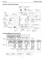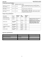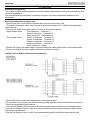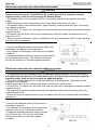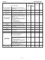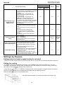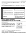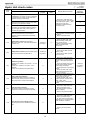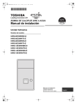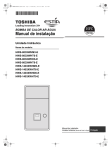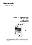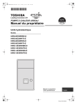
1
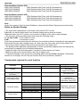
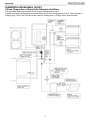
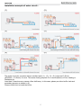
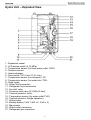
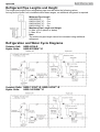
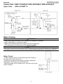
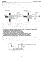
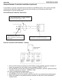
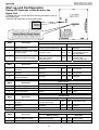
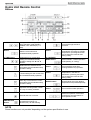
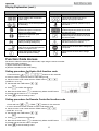
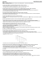
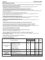
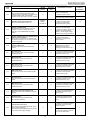
st 1 Draft: 22/10/10 FILE NO : A10-002P Quick Reference AIR TO WATER HEAT PUMP Series 3 Estia System Hot Water Heating or Cooling Radiator Fan coil unit (Heating or Cooling) Outdoor unit Hydro unit Hot water cylinder Under floor heating (Zone Control) Estia Outdoor Unit HWS-803H-E (TR) HWS-1103H-E (TR) HWS-1403H-E (TR) HWS-1103H8-E HWS-1403H8-E HWS-1603H8-E HWS-1103H8R-E HWS-1403H8R-E HWS-1603H8R-E 8.0kW Inverter: single phase 11.2kW Inverter: single phase 14.0kW Inverter: single phase 11.2kW Inverter: three phase 14.0kW Inverter: three phase 16.0kW inverter: three phase 11.2kW Inverter; three phase with heater cord 14.0kW Inverter: three phase with heater cord 16.0kW Inverter: three phase with heater cord Estia Hydro Unit HWS-803XWHM3-E (TR) HWS-803XWHT6-E (TR) HWS-803XWHD6-E HWS-803XWHT9-E HWS-1403XWHM3-E (TR) HWS-1403XWHT6-E (TR) HWS-1403XWHD6-E HWS-1402XWHT9-E (TR) Plate Heat exchanger and 3kW Backup Heater Plate Heat exchanger and 6kW Backup Heater Plate Heat exchanger and 6kW Backup Heater Plate Heat exchanger and 9kW Backup Heater Plate Heat exchanger and 3kW Backup Heater Plate Heat exchanger and 6kW Backup Heater Plate Heat exchanger and 6kW Backup Heater Plate Heat exchanger and 9kW Backup Heater 1 Estia Hot Water Cylinder (EU) HWS-1501CSHM3-E 150L Stainless Steel Tank (with EU Accessories) HWS-2101CSHM3-E 210L Stainless Steel Tank (with EU Accessories) HWS-3001CSHM3-E 300L Stainless Steel Tank (with EU Accessories) Estia Hot Water Cylinder (UK) HWS-1501CSHM3-UK 150L Stainless Steel Tank (with UK Accessories) HWS-2101CSHM3-UK 210L Stainless Steel Tank (with UK Accessories) HWS-3001CSHM3-UK 300L Stainless Steel Tank (with UK Accessories) Note: Under floor heating, Fan Coil units, Radiators, valves and Hot Water Piping are procured locally. Notes on System Design • The input water temperature to the Hydro Unit must be 55°C or less. Especially, be careful when there is an external heating source such as a boiler. When hot water over 55°C returns, it may result in a failure of the unit or water leakage. • The flow rate of the circulating water must meet the following range:11, 14 and 16 kW 17.5 L/minute or more 8 kW 13 L/minute or more If the flow rate becomes less than the minimum, the protective device is activated to stop operation. Ensure the flow rate with a bypass valve, etc. when you use a flow rate valve for the Hydro Unit. • Do not drive water by power other than the pump built in the Hydro Unit. • The backup heater operates supplementary to exert a prescribed capacity when the heat pump cannot exert its capacity at a low outside temperature. • Install the Hydro Unit and water pipes in a place in which they do not freeze. • Make the water circuit closed. Never use it as an open circuit. • To prevent damage to the system the circulating water must be 20 litres or more. If total water amount is not enough, the unit may not function fully due to protective operation. Components required for each function Function Toshiba Supply Procure locally Part name Radiator(s), Fan coil(s), Under floor heating Part name Model code Heating - - Heating & Cooling (All Rooms) - - Fan coil(s) only Heating & Cooling (partly heating only) - - Fan coil(s) plus Radiator(s) or Under floor heating Motorized 2-way valve Hot Water Supply 150L Hot water cylinder 150L Hot water cylinder 210L Hot water cylinder 210L Hot water cylinder 300L Hot water cylinder 300L Hot water cylinder HWS-1501CSHM3-E HWS-1501CSHM3-UK HWS-2101CSHM3-E HWS-2101CSHM3-UK HWS-3001CSHM3-E HWS-3001CSHM3-UK Motorized 3-way valve Earth leakage breaker 2-zone control - - Interlocking with boiler External output board TBC-PCIN3E 2 Motorized mixing valve Circulator pump Buffer tank Boiler Installation Examples Cooling and Heating with Domestic Hot Water When both cooling and heating are used, install a 2-way valve (for cooling) to the pipe to the room for heating only. 3 Installation Examples (cont.) 2-Zone Temperature Control with Domestic Hot Water The following shows an example of the 2-zone temperature control. A buffer tank and a water pump are required for the 2-zone temperature control. This example is Heating only, if the Fan Coils are to be used for Cooling then a 2-Way valve must be fitted. 4 Installation example of water circuit:(1) (2) (3) (4) (5) (6) The water circuit for a system without a buffer tank [ (1) , (2) , (3) , (5) ] requires 17.5l/min (803XWH = 13.0l/min) or more. This water flowing requires 5 or more branches of Floor heating or Radiators etc. Less than 5 branches may cause a flow deficiency. In this case, please provide a buffer tank and secondary pumps, as shown in (4). Please check how to install the boiler. 5 Hydro Unit – Exploded View 1 : Expansion vessel 2 : Hi Pressure switch (4.15 MPa) 3 : Temperature sensor (for Heat pump outlet -TWO) 4 : Pressure sensor 5 : Heat exchanger 6 : Flow switch (13.0 L/min 17.5 L/min) 7 : Temperature sensor (for refrigerant -TC) 8 : Temperature sensor (for water inlet -TWI) 9 : Drain nipple 10 : Water inlet connection 11 : Refrigerant liquid connection 12 : Air relief valve 13 : Pressure relief valve (0.3 MPa (3 bar)) 14 : Thermal protector (auto) 15 : Temperature sensor (for water outlet THO) 16 : Thermal protector (Single operation) 17 : Water pump 18 : Backup heater (3 kW, 3 kW x 2, 3 kW x 3) 19 : Manometer 20 : Water outlet connection 21 : Refrigerant gas connection 6 Refrigerant Pipe Lengths and Height The length and height of the refrigeration pipe must be within the following values. As long as the Hydro Unit is installed within these ranges, no additional refrigerant is required. Minimum Pipe Length HWS-803H-E : 5m HWS-1103H**-E : 5 m HWS-1403H**-E : 5 m HWS-1603H**-E: 5m Maximum Pipe Length and Height H: Max. ±30 m (above or below) L: Max. 30 m Note The maximum pipe length cannot be increased using additional refrigerant. Refrigeration and Water Cycle Diagrams Outdoor Unit: Hydro Units: HWS-803H-E HWS-803XWH**-E Outdoor Units: HWS-1103H**-E, HWS-1403H**-E Hydro Units: HWS-1403XWH**-E 7 Outdoor Units: HWS-1103H8(R)-E, HWS-1403H8(R)-E, HWS-1603H8(R)-E Hydro Units: HWS-1403XWH**-E Water Piping WARNING • Install water pipes according to the regulations of respective countries. • Install water pipes in a freeze-free place. • Make sure that water pipes have sufficient pressure resistance (The setting value of the pressure relief valve is 0.3 MPa). CAUTION • Do not use zinc plated water pipes. When steel pipes are used, insulate both ends of the pipes. • The water to be used must meet the water quality standards specified in EN directive 98/83 EC. Water Circuit • Install a strainer with 30 to 40 meshes (procure locally) at the water inlet of the Hydro Unit. • Install drain cocks (procure locally) for water charge and discharge at the lower part of the Hydro Unit. • Make the piping route a closed circuit. (An open circuit may cause a failure). 8 Water Piping Limitations Design the water pipe length within the QH characteristics of the pump (flow-rate and pump head). The maximum height difference for the water pipes is 7 metres. Piping to hot water tank (option) Water supplied to the hot water cylinder is branched by a motorized 3-way valve (procured locally). Connect the hot water cylinder to port A (open when energized) of the valve. Piping to 2-zone operation (option) To perform 2-zone temperature control circulate water using another pump (procured locally) through a motorized mixing valve (procured locally) and a buffer tank (procured locally). 9 Checking water volume and initial pressure of expansion vessel The expansion vessel of the Hydro Unit has a capacity of 12 litres. The initial pressure of the expansion vessel is 0.1 MPa (1 bar). The pressure of the safety valve is 0.3 MPa (3 bar). Verify whether the capacity of the expansion vessel is sufficient using the following expression. If the volume is insufficient, install an appropriate external expansion vessel. V Action < 12 L Internal Expansion Vessel Size OK > 12 L Internal Expansion Vessel Size too small. Install appropriate external expansion vessel V: Necessary total vessel capacity (L) Ɛ: Vs: P1: Water expansion coefficient at average hot water temperature Total water volume in the closed system (Do not include Hot Water Cylinder) System pressure at tank setting position (Mpa_abs*). (Pipe inner pressure during pump operation before heating device operates = water supply pressure) Maximum pressure used during operation at tank setting position (MPa_abs*). (= safety valve setting pressure) P2: * The absolute pressure value (abs.) is obtained by adding the atmospheric pressure (0.1 MPa (1 bar)) to the gauge pressure. Water temperature and expansion coefficient (Ɛ) Water temperature and expansion coefficient (Ɛ) Expansion rate Hot water temperature (°C) Hot water temperature (°C) (Ɛ) 0.0002 0.0000 0.0000 0.0003 0.0008 0.0017 0.0029 0.0043 0.0050 0.0078 0.0100 0 4 5 10 15 20 25 30 35 40 45 50 55 60 65 70 75 80 85 90 95 - Example Maximum Hot Water temperature: 55°C Initial water charge: 0.2MPa System volume: 200 L. Calculate Vessel capacity (V):V = 0.0145 x 1 V = 200 (0.2 + 0.1) (0.3 + 0.1) 11.6L In this case V < 12 L therefore the internal expansion vessel is sufficient, so there is no need to install an external expansion vessel. 10 Expansion rate (Ɛ) 0.0121 0.0145 0.0171 0.0198 0.0229 0.0258 0.0292 0.0324 0.0961 0.0967 - Pump operation / configuration HWS-803XWHM3-E, T6-E, D6-E, T9-E HWS-1403XWHM3-E, T6-E, D6-E, T9-E 11 Water charging Charge water until the pressure gauge shows 0.2 MPa (2 bar). Hydraulic pressure may drop when the trial run begins. In that case, add water. Air may enter if the charged hydraulic pressure is low. Loosen the Air relief valve cap by two turns to release air (see diagram). Loosen the cap of the pressure relief valve to release air. Water may come out of the pressure relief valve. Release the air completely from the water circuit. Failure to do so may disable correct operation. Water quality The water used must satisfy EN directive 98/83 EC. Piping insulation It is recommended that insulation treatment be applied to all pipes. To perform optional cooling operation, apply insulation treatment of 20 t or more to all pipes. 12 Electrical Connections E Box layout Power Lines Schematic 13 Control Lines Schematic Terminal Block Connections 14 Electrical supply / cable specifications Wiring specifications (power line) Wiring specification (control line) 15 Control parts specifications Output line specifications Input line specifications Description Input Maximum length Emergency stop control Non-voltage 12 m Cylinder thermostat input Non-voltage 12 m Cooling thermostat input Non-voltage 12 m Heating thermostat input Non-voltage 12 m 16 CAUTION Earthing arrangements The Hydro Unit and related equipment must be earthed in accordance with your local and national electrical regulations. It is essential that the equipment is earthed to prevent the electric shock and damage to the equipment. Electrical connection to hydro unit • Remove the front cover and the electrical box cover from the Hydro Unit. • The Hydro Unit power cable must be sized in accordance with refer to “Electrical supply/cable specifications”. • Connect the Hydro Unit power cable to Terminal 02 as shown below. Single Phase Units: Live conductor – Terminal L1 Neutral conductor – Terminal L2 Earth conductor – Earth terminal Three Phase Units: Phase 1 conductor – Terminal L1 Phase 2 conductor – Terminal L2 Phase 3 conductor – Terminal L3 Neutral conductor – Terminal N Earth conductor – Earth • Ensure the Hydro Unit power cable is secured using the cable clamp fitted in the electrical box. • Ensure the Hydro Unit power cable connection terminals are tight. Outdoor unit to hydro unit electrical connection • Ensure electrical circuits are isolated before commencing work. • The Outdoor Unit to Hydro Unit interconnecting cable must be sized in accordance with refer to “Electrical supply/cable specifications”. • Connect the Outdoor Unit to Hydro Unit interconnecting cable as shown in the diagram above. • Ensure the Outdoor Unit to Hydro Unit interconnecting cable is secured using the cable clamp fitted in the electrical box. • Ensure the Outdoor Unit to Hydro Unit interconnecting cable connection terminals are tight. 17 Electrical connection for external booster heater CAUTION • The maximum current available from the booster heater output is 1 A. Do not connect the booster heater directly to Terminal Block 05 on the Hydro Unit. A separate contactor, supplied locally, must be used to supply the booster heater. • The booster heater can be installed only for room heating and cannot be used for hot water supply. • Install the booster heater downstream of the 3-way valve on the indoor unit side. • The booster heater is an external heater, supplied locally, used to assist the Hydro Unit during low ambient conditions. • The AC230 V 1 A output from the Hydro Unit must only be used to energize an external contactor (supplied locally). • The output from the Hydro Unit is only enabled when either the outdoor air temperature to be lower than -20°C. • Ensure the external booster heater is installed and set up in accordance with all Local, National and International regulations. • Connect the external booster heater to the Hydro Unit according to the diagram shown opposite:• The contactor will energize in the event of low ambient conditions. • A separate dedicated electrical supply must be used for the external booster heater. This must be connected through the contacts on the field supplied contactor. Electrical connection for external additional pumps CAUTION • The maximum current available from the additional pump output is 1 A. Do not connect the additional pump directly to Terminal Block 05 on the Hydro Unit. A separate contactor, supplied locally, must be used to supply the additional pump. • The Hydro Unit has the facility to connect an additional circulating pump, if required, into the heating or cooling system. • Install the pump so that its motive power does not affect the internal pump. • The AC230 V 1 A output from the Hydro Unit must only be used to energize an external contactor (supplied locally). • The output for the pump is synchronized with the operation of the main circulating pump (P1) inside the Hydro Unit. • Ensure the pump is installed and set up in accordance with all Local, National and International regulations. • Connect the additional pump (P2) as shown in the diagram opposite:• The contactor will energize synchronously with operation of the main circulation pump (P1). • A separate dedicated electrical supply must be used for the pump. This must be connected through the contacts on the field supplied contactor. 18 3-way valve (diverter) connection Required Valve Specification: Electrical Specification: 230 V; 50 Hz; <100 mA Valve Diameters: Port A, Port B: Ø 1 1/4" Return Mechanism: 3 types of 3-way valve (diverter) can be used. Set the 3-way valve in use with the DIP switch SW13-1 on the Hydro Unit board. Diverter Valve Type 1 Type 2 Type 3 Description 2-wire spring return 3-wire SPST 3-wire SPDT SW13-1 OFF OFF ON NOTE Continuous operation of the valve motor at the fully open position is not recommended. • The 3-way diverter valve is used to select either domestic hot water or zone1 / zone2. • Connect the 3-way diverter valve in accordance with the diagram below:- 19 3-way mixing valve connection Required Actuator Specification Electrical Specification:230 V; 50 Hz; <100 mA The 3-way mixing valve is used to achieve the temperature differential needed in a 2-zone heating system. • Connect the 3-way mixing valve in accordance with the diagrams below:- Hot water cylinder connection (optional) • Please refer to “Electrical supply/cable specifications” for fuse/cable size and for connection details. Electrical Connection (Hot Water Cylinder Electric Heater) • The electric heater, incorporated in the hot water cylinder, requires a separate supply to the Hydro Unit. • Connect the hot water cylinder heater electrical supply in accordance with shown below: Live conductor: Terminal L on Terminal Block 03 Neutral conductor: Terminal N on Terminal Block 03 Earth Conductor: Earth terminal on Terminal Block 03 • Connect the hot water cylinder heater to the Hydro Unit as shown below: Live conductor to hot water cylinder: Terminal 1 on Terminal Block 03 Neutral conductor to hot water cylinder: Terminal 2 on Terminal Block 03 Earth conductor to hot water cylinder: Earth terminal on Terminal Block 03 Electrical Connection (Hot Water Cylinder temperature Sensor) • Connect the hot water cylinder temperature sensor as shown below to terminals A & B on Terminal Block 06 in the Hydro Unit. • Please ensure that the interconnecting cable, between the Hydro Unit and the hot water cylinder, is connected to earth at both ends of the cable using the shield wire. 20 Second Remote Controller Installation (optional) It is possible to connect a second remote controller to the ESTIA system. The remote controller can be set as either the header or second remote controller and to measure either water temperature or room air temperature. Second Remote Controller Connection 2 core shielded cable – 0.5mm2 or more. Maximum cable length – 50m Terminal block TB07, for remote controller connection, to hydro unit. Second remote controller connections. Terminals A and B are non polar. Remote Controller DIPS Switches - Setting Set one of the remote controllers as the header remote controller (remote controller of hydro unit is preset as the header remote controller (DPSW1 = OFF) Set the DPSW’s on the other remote controller PC boards to “second” (optional remote controller is preset as “second” – DPSW1 = ON) For room air temperature measurement set function code 40 (on the hydro unit) to “1” Set DPSW2 to ON on the remote controller used for room temperature measurement Either the header or the second remote controller can be set for room temperature measurement 21 Start up and Configuration Setting DIP Switches on the Board in the Hydro Unit • Detach the front cover and the electric parts box cover of the Hydro Unit. • Set the DIP switches on the main board. SW10 Description 1 Pump P1 control during hot water production 2 Pump P1 control using outside air temperature 3 External P2 pump operation SW11 1 2 3 SW12 Switch mode Default setting P1 stops when heat pump stops (cylinder heater ON) OFF ON Normal Control OFF ON Continuous operation (P2 OFF when remote controller OFF) OFF ON Switch mode Description Internal backup heater operation Hot water cylinder heater operation Booster heater output enabled/disabled Alternate P1 continuous operation P1 operation controlled by outside air temperature Interlocked with the internal pump synchronised with P1. Default setting Alternate Operate OFF ON Not operate Operate OFF ON Not operate Enabled OFF ON Disabled Switch mode Description Default setting Alternate 1 Hot water supply operation Valid OFF ON Invalid 2 Zone 1 operation Valid OFF ON Invalid 3 Zone 2 operation Invalid OFF ON Valid SW13 3 3WV selection – 2 wire/SPST or SPDT Boiler output enabled / disabled Auto restart for power failure SW02 Description 1 2 Switch mode Description Default setting Alternate • 2-wire spring return type • 3-wire SPST type OFF ON 3-wire SPDT type Disabled OFF ON Enabled Auto restart OFF ON Manual restart Switch mode Default setting 1 Boiler installation position Before 3 way valve OFF ON 4 Room thermostat input Invalid OFF ON 22 Alternate After 3 way valve (heating side) Valid Hydro Unit Remote Control Buttons 1. TEMP. button: 2. SCHEDULE button: 3. TIME button: 4. SET button: Changes the set temperature for each operation mode (ZONE1 / ZONE2 / HOT WATER) by 1°C step. Sets the current time and scheduled weekly operation. 11. AUTO TEMP. button: 12. OPERATE MODE button: Determines the entered current time setting and scheduled weekly operation setting. 13. ZONE1, 2 button: Clears settings for the current time and scheduled weekly operation. 7. STEP button: Controls the night set back operation. Changes time for current time setting and scheduled weekly operation setting with ▼ and ▲ buttons. 5. CL button: 6. DAY button: 10. NIGHT button: Sets days of the week for current time setting and scheduled weekly operation setting. Specifies switching STEP number in a day for weekly schedule. 8. TEST button: 14. ANTI BACTERIA button: 15. HOT WATER BOOST button: 16. HOT WATER button: 17. SELECT button: Used for test run or service. 9. FROST PROTECTION button: Switches setting temperature automatically according to outside temperature. (Pressing this button long changes the mode to data setting mode). Selects ZONE1 / ZONE2 operation mode (heating or cooling). Turns on/off the zone (floor heating/radiator/FCU) operation. Regularly increases the hot water temperature in the tank for sterilization. (Pressing this button long changes the mode to data setting mode). Boosts boiling when high tapping temperature is required temporarily. Turns on/off hot water operation. Selects an operation mode when changing the set temperature of each operation mode. Controls minimum operation for unused period (going out, absence,etc.) for anti freezing. NOTE Some functions are not provided depending on the system specification in use. 23 Display Explanation 18: ZONE1, ZONE2 Display 20: HOT WATER Description Lights when floor heater or radiator is connected (when the system has floor heater or radiator). Display Description Lights when hot water supply system is connected (when the system has hot water supply). ZONE1 selected for Temperature to be changed. Lights when system configured to have 2 zones. °C ZONE2 selected for Temperature to be changed. HOT WATER selected for Temperature to be changed. Lights during heating or cooling operation using the heat pump. Lights when hot water supply operation is performed by heat pump. Lights when the internal heater is energized during heating operation. Lights when the internal heater is energized during hot water supply operation. Lights when heating is selected. Lights during hot water supply operation. Lights when cooling is selected. Lights while hot water boost is activated. Lights when the FROST PROTECTION button is pressed and goes out when the button is pressed again. Lights when the ANTI BACTERIA button is pressed and goes out when the button is pressed again. Lights when Auto operation is selected. Lights when unit enters the data set mode. Displays heating/cooling set temperature. (Heating: 20 to 55°C, factory setting: Auto, cooling: 10 to 30°C) Goes out when Auto operation is selected. Lights when the set temperature or sensor's water temperature is displayed with the 7-segment indicator. Displays hot water set temperature. (40 to 75°C, factory setting: 65°C) °C 24 Lights when the set temperature or sensor's water temperature is displayed with the 7-segment indicator. Display Explanation (cont.) 19: TIMER Display 21: CONTROL Description Display Description Clock: Displays the current time (AM or PM). Lights while internal pump (P1) or external pump (P2) is driven. Displays days of the week (Sunday to Saturday). Lights during backup operation only by the heater. Lights when the NIGHT button is pressed and goes out when the button is pressed again. Lights when the unit enters the data set mode and goes out when the unit exits the data set mode. Lights when the unit enters the service mode and goes out when the unit exits the service mode. Lights when night time quiet operation is set. Indicates scheduled operation 1 status (including setting time). Lights when an error occurs and goes out when the error is cleared. Displays the scheduled operation step when the scheduled operation STEP1-5 program is set. Lights for two seconds when settings are completed. Lights during time setting and scheduled operation setting. Lights for two seconds when settings failed. Function Code Access Set function codes for various operation modes, input using the remote controller. There are 2 types of settings:1) Hydro Unit function code setting. 2) Remote controller function code setting. Setting procedure for Hydro Unit function code 1. Press and hold + + buttons for four seconds or more to enter the hydro unit function code setting mode. 2. Set the function code number with the TEMP. buttons (CODE No.: 01 to 91). 3. Set data with the TIME buttons 4. Press . to confirm the settings. 5. Note that the Clear button is enabled only before the SET button is pressed and the function code is changed. 6. Press to exit the settings menu. Setting procedure for Remote Controller function code 1. Press and hold + + TEMP. buttons for four seconds or more to enter the remote controller function code setting mode. 2. Set the function code number with the TEMP. buttons (CODE No.: 01 to 13). 3. Set data with the TIME buttons 4. Press . to determine the settings. 5. Note that the Clear button is enabled only before the SET button is pressed and the function code is changed. 6. Press to exit the settings menu. 25 Main setting items (refer to Function code setting table – shown below descriptions) (1) Setting Hot Water Temperature Range (function codes: 18 to 1F) • Set the temperature range for heating (zone 1, zone 2), cooling, and hot water. • The upper-limit and lower-limit temperatures of each mode can be set. (2) Setting Heat Pump Operation Conditions for Hot Water Supply (function codes: 20 and 21) • Set the heat pump start water temperature and heat pump stop water temperature. • The heat pump starts working when the water temperature lowers below the set start water temperature. It is recommended that the default value be used. (3) Compensating Hot Water Temperature (function codes: 24 and 25) • Compensate the target temperature from the remote controller set temperature when the hot water temperature lowers below the set outside air temperature. (4) Setting Hot Water Boost (function codes: 08 and 09) • Set the control time and target temperature when the HOT WATER BOOST is pressed. button on the remote controller (5) Setting Anti-Bacteria (function codes: 0A and 0B / Remote controller 0D and 0C) is set with the remote controller. • Set the control for the hot water cylinder when ANTI BACTERIA • Set the target temperature, control period, start time (24-hour notation), and target temperature retention period. • Make this control setting according to regulations and rules of respective countries. (6) Setting System Priority Mode (function codes: 22, 23 and 0F) • Set the outside air temperature that changes the preferred operation mode. • Hot Water - Heating Switching Temperature Heating operation takes precedence when the temperature lowers the set temperature. • Boiler HP Switching Temperature When the temperature lowers the set temperature, the HP operation stops and the external boiler output is made. Cooling – Hot Water Priority Selection Set the priority mode between cooling and hot water when the system is running in cooling mode (7) Setting Heating Auto Mode Temperature (function codes: 27 to 31) • Compensate the target temperature when Auto is set for temperature setting on the remote controller. • The outside air temperature can be set to one of three points (T1 and T3 customisable) within a range of -15 to 15°C. • The target temperature can be set to a value from 20 to 55°C. • However, A > B > C > D > E. • The entire curve can be adjusted plus and minus 5°C by function code 27. (8) Setting Frost Protection Temperature (function codes: 3A and 3B / Remote controller 12 and 13) • Set the function when the FROST PROTECTION button on the remote controller is pressed. • Set enabling/disabling of this function and the target water temperature. (FC3A and FC3B) Set schedule end day and end time (remote controller: Fc12 and 13) • If disabling is set, the frost protection operation is not performed even when the FROST PROTECTION is pressed. button (9) Setting Frequency of Output to Internal Backup Heater (function codes: 33 and 34) • The increase/decrease time is used to set the response time. (10) Setting Night Setback (function codes: 26 / Remote controller 0F to 11) button on the remote controller is pressed. • Set the function when the NIGHT • Set enabling/disabling of this function, reduction temperature, start time, and end time. • If disabling is set, the night setback operation is not performed even when the NIGHT 26 button is pressed. Main setting item (cont.) (11) Setting second remote controller (room temperature measurement) (function codes: 40, 92, 93, 94, 95, 96, 9D and remote control function codes 02 and 03) • When system control is required using room air temperature make these settings to enable this function. • Enable the room temperature control using FC40 • Set upper and lower heating / cooling temperature limits using FC’s 92, 93, 94 and 95 • Set initial target water temperatures for heating and cooling using FC’s 96 and 9D • Set room temperature offsets for heating and cooling using remote controller FC’s 02 and 03 • Set remote controllers as header / second and room temperature/water temperature functions using DPSW’s 1 and 2 on the remote controllers. (12) Setting 2-Way Valve (for Cooling) Operation (function code: 3C) • When using both cooling and heating operations and there is an indoor unit only for heating (such as floor heating), install the 2-way valve and set this function code. (13) Setting 3-Way Valve Operation (function code: 54) • This setting is not necessary for normal installation. Make this setting to invert the logic circuit in case ports A and B of the 3-way valve are wrongly attached and it cannot be rectified on site. (14) Mixing valve types and setting (function code: 0C) • Set the time period from full close to full open of the 2-zone control mixing valve. Set a value that is 1/10 of the actual time. (15) Setting Heating/Hot Water Switching when Boiler Is Used (function code: 3E) • When boiler is used, make this setting to operate the Hydro Unit by the instruction from the boiler. (16) Setting Heat Pump Operating Time for Hot Water Supply Operation (function code: 07) • Set the time period from the start of heat pump run to the start of heater energization at the beginning of hot water supply operation. If a long period is set, it takes long time for heating water. (17) Setting Cooling ON/OFF (function code: 02) • Set this function when performing cooling operation. (18) Remote controller time indication (function code: Remote controller 05) • 24-hour or 12-hour notation is selected for the timer. (19) Setting Nighttimes Quiet Operation (function codes: Remote controller 09 to 0B) • Issue an instruction for low-noise mode operation to the outdoor unit. Enabling/disabling of this function, start time, and end time can be set. (20) Setting Alarm Tone (function code: Remote controller 11) • The remote controller alarm tone can be set. Function Code Setting Function Code Setting Address Function Code Setting (1) Setting Temperature Range (2) Hot Water Operation (3) Hot Water Temperature Compensation (4) Hot Water Boost Heating Upper Limit - Zone 1 Heating Lower Limit - Zone 1 Heating Upper Limit - Zone 2 Heating Lower Limit - Zone 2 Cooling - Upper Limit Cooling - Lower Limit Hot Water - Upper limit Hot Water - Lower limit Heat Pump Start Temperature Heat Pump Stop Temperature Temperature Compensation Outside Air Temperature (°C) Compensation Temperature (°C) Operation Time (x10 min) Setting Temperature (°C) 27 Range Default - 37~55°C 20~37°C 37~55°C 20~37°C 18~30°C 10~20°C 60~80°C 40~60°C 20~45°C 40~50°C 55 20 55 20 25 10 75 40 38 45 24 - -20~10°C 0 25 08 09 - 0~15°C 3~18 40~80°C 3 6 75 Hydro Unit Remote Controller 1A 1B 1C 1D 18 19 1E 1F 20 21 Function Code Setting Address Function Code Setting (5) Anti Bacteria (7) Heating Auto Curve Settings (8) Frost Protection (9) Back Up Heater Control (10) Night Setback (11) Room temperature Remote Controller Range Default 0D 0C - 70~80°C 1~10 0~23 0~60 -15~0°C 0 0~15°C 20~55°C 20~55°C 20~55°C 20~55°C 20~55°C 0~100% -5~5°C 75 7 22 30 -10 0 10 40 35 30 25 20 80 0 3A 3B - 12 13 0~1 10~20°C 0~20 0~23 1 15 0 0 Downtime Back Up Heater 0=5min; 1=10min;2=15min;3=20min 33 - 0~3 1 Uptime Back Up Heater 0=10min; 1=20min; 2=30min; 3=40min 34 - 0~3 0 Change Setback Temperature 26 - 3~20°C 5 Zone selection 0=Zone 1 & 2; 1= Zone 1 Only 58 - 0~1 1 Start Time (Hour) - 0E 0~23 22 End Time (Hour) - 0F 0~23 06 Room Temperature Control: 0 = Invalid; 1 = valid 40 - 0~1 0 Setting Room Temperature Range: Cooling room temperature upper limit (°C) 92 - 15~30 29 Setting Room Temperature Range: Cooling room temperature lower limit (°C) 93 - 15~30 18 Setting Room Temperature Range: Heating room temperature upper limit (°C) 94 - 15~30 29 Setting Room Temperature Range: Heating room temperature lower limit (°C) 95 - 15~30 18 Room Temperature Offset: Heating room temperature offset value (sensor temperature – control temperature °C) - 02 -10~10 -1 Room Temperature Offset: Cooling room temperature offset value (sensor temperature – control temperature °C) - 03 -10~10 -1 Initial Target Water Temperature – Cooling: Room temperature controller or external room thermostat (°C) 96 - 10~25 20 Initial Target Water Temperature – Heating: Room temperature controller or external room thermostat (°C) 9D - 20~55 40 Hydro Unit Remote Controller Setting Temperature (°C) Start Cycle (Day) Start Time (Hour) Operation Time (min) Outside Temperature T1 (°C) Outside Temperature T2 (°C) Outside Temperature T3 (°C) Setting Temperature A @ OAT -20°C (°C) Setting Temperature B @ OAT T1 (°C) Setting Temperature C @ OAT T2 (°C) Setting Temperature D @ OAT T3 (°C) Setting Temperature E @ OAT 20°C (°C) Ratio Of Zone 2 In Zone 1 Auto Mode (%) Auto Curve - Temperature Shift (°C) 0A 0B 29 2B 2C 2D 2E 2F 30 31 27 Function 0=Invalid; 1=Valid Frost Protection Setting Temperature (°C) Frost Protection – Schedule End Day Frost Protection – Schedule End Time 28 Function Code Setting Address Hydro Remote Unit Controller Function Code Setting Range Default Cooling 2 Way Valve - Operation Logic 0=Activated during cooling; 1=Not activated during cooling 3C - 0~1 0 (13) Hydro 3 Way Diverting Valve Operation Control 3 Way Diverting Valve Operation Logic 0=Activated during hot water operation; 1=not activated during hot water operation 54 - 0~1 0 (14) 2 Zone Mixing Valve Drive Time Specified Drive Time for Mixing Valve (x10sec) Mixing valve OFF (control time - mins) External Boiler/Heat Pump Synchronisation 0=Synchronised – external boiler stops as temperature reaches hydro unit’s temperature setting 1=Not synchronised Boiler/Heat Pump/Electric Heater Operation During Low Ambient Conditions (controlled using FC23) 0 = HP & boiler operation 1 = Boiler operation only 2 = Electric heater operation only 0C 59 - 3~24 1~30 6 4 3E - 0~1 0 5B - 0~2 0 Maximum Heat Pump Operation Time In Hot Water Operation Priority Mode (minutes) 07 - 1~120 30 (17) Cooling Operation 0=Cooling & Heating Operation; 1=Heating Only Operation 02 - 0~1 1 (18) Remote Controller Indication 24h or 12h Time Indication 0= 24h; 1=12h - 05 0~1 0 Low Noise Operation 0=Invalid; 1=Valid Start Time (Hour) End Time (Hour) Tone Switching 0=OFF; 1=ON - 09 0A 0B 11 0~1 0~23 0~23 0~1 0 22 06 1 64 - 0~1 0 65 - 0~1 0 9E - 10~30 20 42 - 0~1 0 (12) Hydro 2 Way Valve Operation Control (15) Boiler/Heat Pump Synchronisation (16) Maximum Operation Time Of Hot Water Heat Pump (19) CDU Night Time Low Noise Operation (20) Alarm Tone Pump P2 Control in Cooling Mode: 0 = P2 continuous operation 1 = P2 stops in cooling mode Pump Control / Synchronisation Pump P2 Remote Controller Display Synchronise Pump P1 with Room Temperature Control and External Room Thermostat Control: 0 = P1 continuous operation 1 = P1 synchronised with room temperature / thermostat control. P1 will stop when HP in thermo OFF mode Pump P1 Operation: outside Air Temperature Control in Heating Mode (°C): P1 stops when TO > set value in FC9E with DPSW10_2 ON (heating mode only) 0=Not Shown; 1=Shown 29 Function Code Setting Address Function Code Setting E-Stop Switch Logic / System Restart & TEMPO Control Hydro Unit Capacity Setting A02 Error Detection With Boiler Output Enabled Output Signal Setting Forced stop input – switch logic: 0 = Contacts low > high (terminals 1-3 CLOSE) system stop. System restart with remote controller 1 = Contacts high > low (terminals 1-3 OPEN)system stop. System restart with remote controller 2 = Contacts high > low (terminals 1-3 OPEN)system stop. Contacts low > high (terminals 1-3 CLOSE) system restart 3 = Contacts low > high (terminals 1-3 CLOSE) system stop. Contacts low > high (terminals 13 CLOSE -second time) system restart (PULSE INPUT) System Restart Logic / TEMPO Control: 0 = System restarts in heating and hot water mode 1 = System restarts in the last mode prior to stopping 2 = System restarts in heating mode 3 = System restarts in hot water mode 4 = TEMPO Control 1: All electric heaters disabled 5 = TEMPO Control 2: HP and all electric heaters disabled 0012 = 803XWH**E 0017 = 1403XWH**E Factory set but function code is needed for PCB replacement Allows A02 Error Detection to be Activated / Deactivated When Boiler Output Is Enabled: 0 = A02 activated then boiler output OFF 1 = A02 deactivated and boiler output stays ON Output Signal Setting with Optional PCB Connected to CN209: 0 = EMG terminals = output On during defrost; OPERATION terminals = output ON when compressor is running 1 = EMG terminals = output ON when error detected; OPERATION terminals = output ON during operation (remote controller ON) Range Default - 0~3 0 61 - 0~5 0 01 - 0012 or 0017 Depends on Hydro Unit 62 - 0~1 0 67 - 0~1 0 Hydro Unit Remote Controller 52 Settings by Purpose Settings when hot water supply function is not used • When the hot water supply function is not used, set DIP SW12-1 on the Hydro Unit board to ON (refer to page 18). Setting for cooling • For Space Conditioning Units that do not perform cooling (radiators and Under floor heating, etc.), procure a motorized 2-way valve (for cooling) locally and attach it to the water pipe that is not used for cooling. Connect the valve cables to terminals TB05 (3) and (4) of the Hydro Unit. • Press and hold + + switches on the remote controller to change the Hydro Unit function code, and change address 02 to 0, and then press the SET button to enable the function. Press the TEST button to exit the setting mode. • Stick the optional insulation for cooling to the bottom of the Hydro Unit. 30 Settings for hot water supply • Prepare the optional hot water cylinder. • Procure a motorized 3-way (diverter) valve locally and perform piping. Connect the valve cables (as described in Electrical connection section). • Set DIP SW12-1 on the Hydro Unit board to OFF. • Connect the power supply unit for the hot water cylinder heater to terminals TB03 L and N of the Hydro Unit. • Connect cables between the Hydro Unit and the hot water cylinder as follows: Hydro Unit terminals TB03 (1), (2), and earth — Hot water cylinder (1), (2), and earth TB06 A, B, and earth — Hot water cylinder A, B, and earth Settings for 2-zone temperature control • Procure a motorized mixing valve locally and perform piping. Connect the valve cables (as described in Electrical section). • Procure a buffer tank locally. • Procure a water pump locally, and connect its cables (as described in Electrical section). • To inhibit interlocking the water pump with the internal pump of the Hydro Unit, set DIP SW10-3 on the Hydro Unit board to OFF. • Set DIP SW12-3 on the Hydro Unit board to ON. Attach the temperature sensor (TFI) connected to terminals TB06 C and D of the Hydro Unit near the hot water inlet of the Hydro Unit. • Fix TFI sensor on the room heating supply pipe by using the connector procured in locally. • Cover the cables with insulation tube (minimum 1 mm) or conduit so that the user cannot touch them directly. • Cover the TFI sensor's cables and sensor with insulation tube (minimum 1 mm) shown in the diagram on the right. Test Run Once you have competed the installation and system configuration conduct a test run (see below). Since the protection setting is disabled in the TEST mode, do not continue a test run longer than 10 minutes. • Press the TEST button on the remote controller. An indication “TEST” appears on the remote controller. button and select “heating” with the OPERATE MODE button. • Press the ZONE1, 2 The pump is activated in 30 seconds. If air is not released completely, the flow switch is activated to stop operation. Release air again according to the piping procedure. Little air bite is discharged from the purge valve. • Check that the air bite sound disappears. • Check that the hydraulic pressure has become the predetermined pressure 0.1 to 0.2 MPa (1 to 2 bar). If the hydraulic pressure is insufficient, replenish water. • Heating operation starts. Check that the hydro unit starts heating. • Press the OPERATE MODE button and select “cooling.” • Cooling operation starts. Check that the hydro unit starts cooling and that the floor heating system is not cooled. • Press the ZONE1, 2 button to stop operation. button to start hot water supply operation. • Press the HOT WATER • Check that there is no air bite. • Check that hot water is present at the connection port of the hot water cylinder. button to stop the hot water supply operation. • Press the HOT WATER • Press the TEST button to exit the test mode. 31 Sensor Temperature Monitoring Function The sensor sensing temperature is displayed on the remote controller. This function allows you to make sure whether the sensor is installed properly. 1) Press + buttons for four seconds or more. 2) Select the Code No. with the TEMP. Code No. Location buttons. Indication Unit 00 Control Temperature (Hot water cylinder) °C 01 Control Temperature (Zone1) °C 02 Control Temperature (Zone2) °C 03 Remote controller sensor temperature °C 04 Condensed temperature (TC) °C Water inlet temperature (TWI) °C Water outlet temperature (TWO) °C 08 Water heater outlet temperature (THO) °C 09 Floor inlet temperature (TFI) °C 0A Hot water cylinder temperature sensor (TTW) °C 0B Motorized mixing valve position step 0E Lo pressure (Ps) x 100 MPa 06 07 Hydro unit 60 Heat exchanger temperature (TE) °C 61 Outside air temperature (TO) °C 62 Refrigerant discharge temperature (TD) °C 63 Refrigerant suction temperature (TS) °C 65 Heat sink temperature (THS) °C Current value (in the inverter) A 6D Heat exchanger coil temperature (TL) °C 70 Compressor operating frequency Hz 72 Number of revolutions of outdoor fan (lower) rpm 73 Number of revolutions of outdoor fan (upper) rpm 74 Outdoor PMV position x1/10 pls F0 Micro computer energized accumulation time x100hrs F1 Hot water compressor ON accumulation time x100hrs Cooling compressor ON accumulation time x100hrs Heating compressor ON accumulation time x100hrs F4 Hydro unit AC pump operation accumulation time x100hrs F5 Hot water cylinder heater operation accumulation time x100hrs F6 Hydro unit heater operation accumulation time x100hrs F7 Booster heater operation accumulation time x100hrs 6A F2 F3 3) Press Outdoor unit Service Data button to exit the test mode. 32 Non-defective operation (program operation)…….No Check code displayed In order to control the heat pump unit, there are the following operations as the built-in program operations in the microcomputer. If a claim occurs about the operation, please confirm whether it falls under any of the contents in the following table. If it does, please understand that the symptom is not a defect of the equipment, and it is an operation necessary for the control and maintenance of the heat pump unit. No. 1 2 3 4 5 Operation of the heat pump system Explanation The compressor sometimes does not operate even within the range of compressor “ON”. The compressor does not operate during the operation of the compressor reboot timer (3 min). Even after the power activation, the compressor reboot timer continues to be active. It may be caused by the high temperature release control (release protection control by the temperature of the water heat exchanger) or the current release control. During the hot water supply or heating operation, without reaching the set temperature, the compressor operation frequency stays at a frequency of less than the maximum Hz or lowers down. The “Stop” operation on the remote control will not stop the circulating pump. (The same for hot water supply, heating and cooling) In order to deal with the temperature increase in the heat exchanger after stopping, the operation continues for 1 min after the compressor is stopped. “ON” on the remote control will not operate the compressor. (It will not operate even after the reboot delay timer elapsed) When the outdoor temperature (TO sensor detection temperature) is -20°C or lower, the heat pump will not operate in order to protect the compressor, and the heater will operate instead. When the power is turned on,operating the remote control. • • • it starts operation without The auto restart operation may be working. The antifreeze operation may be working. If the TWI, TWO or THO sensor detects a temperature below 4°C, the operation changes from circulating pump --->> circulating pump + heater.) Defective operation check codes How to determine from the check code on the remote control If the defect is limited by the check code displayed on the remote control, please repair the defect based on the table on the next page. The check codes are separated into two groups: software and hardware errors. Since a hardware error cannot be cancelled without a part replacement etc., please perform a repair. If its abnormality is determined, the abnormality is noticed by indicating the check code on the remote control check code display part while letting off a buzzer. How to cancel a check code on the remote controller (1) Press (2) Press or button (on the operation side) to clear the check code. to stop a buzzer for an abnormality only. Although the above procedure cancels the check code, the hardware error will be displayed again until the hardware repair is completed. 33 o…...…. Possible x…. Not possible Hydro Unit check codes Check code Diagnostic functional operation Operational cause Backup present Automatic reset Pump or flowing quantity error 1) Detected by TC sensor TC 63°C is detected in the heating or hot water supply heat pump operation (except for defrosting). 3) Detection of chattering abnormality in the flow switch input Chattering detection: Detects input changes (OFF⇔ON) 4 times within 10 seconds during operation. Defect frequency confirmation 4 2) Detected by flow switch abnormality When no signal of the flow switch is showing 2 min after the built-in pump operation started. A01 Determination and action × × 1. Almost no or little water flow. • Not enough vent air • Dirt clogging in the water piping system. • The water piping is too long. • Installation of buffer tank and secondary pump 2 4 4) Disconnection of the flow switch connector When the stopped built-in pump starts its operation, the flow switch status is detecting "water flow". 1. Disconnection of the flow switch connector. 2. Defect of the flow switch. 2 A02 Temperature increase error (heating) When one of the TWI, TWO and THO sensors exceeds 70°C. Heating O Hot water × O 1. Check the water inlet, water outlet and heater outlet (TWI, TWO, THO) sensors. 2. Defect of the backup heater (defect automatic reset thermostat). 1 A03 Temperature increase error (hot water supply) When the TTW sensor exceeds 85°C. Heating O Hot water × O 1. Check the hot water cylinder sensor (TTW). 2. Check the hot water cylinder thermal cut-out. 1 A04 Antifreeze operation 1)TWO>20°C condition: 2×TC+TWO < -12°C is detected. 2)TWO 20°C condition: TC+TWO < 4°C is detected. 3)TWI 10°C is detected during defrosting. O × A05 Piping antifreeze operation Activating the heater under the condition of TWO<4orTWI<4orTHO<4 does not achieve TWO,TWI,THO 5°C after 30 min elapsed. O O A07 Pressure switch operation The pressure switch operates for 300 sec continuously during the heat pump operation. A08 Low pressure sensor operation error The low pressure sensor detected 0.2 MPa or less. O × O 1. Almost no or little water flow. • Dirt clogging in the water piping system. • The water piping is too long. 2. Check the heater power circuit. • Power supply voltage, breaker, power supply connection 3. Set the presence of the backup heater. 4. Check the water inlet, water outlet and heat exchange (TWI, TWO, TC) sensors. 1. Check the heater power circuit. • Power supply voltage, breaker, power supply connection 2. Check the water inlet, water outlet and heater outlet sensors (TWI,. TWO, THO). 3. Disconnection of the backup heater. Heating 2 Hot water 2 Cooling 4 1 1. Almost no or little water flow. 2. Defect of the flow switch. 3. On-load operation under the above conditions. 4. Defect in the pressure switch. 1 1. Almost no or little water flow. 2. Defect of the flow switch. 3. On-load cooling or prolonged defrosting (a lot of frost formation) under the above conditions. 8 4. Defect in the low pressure sensor. 2 × 34 Check code A09 Diagnostic functional operation Operational cause Overheat protection operation When the thermostat of the backup heater activates during the operation of the heat pump or backup heater. When the thermostat operation is activated while it has been stopped. Backup present O Automatic reset Defect frequency confirmation 1. No water (heating without water) or no water flow. 2. Defect of the flow switch. 2 3. Defect of the backup heater (poor automatic reset thermostat). 1 × 1. Almost no water flow. 2. Defect of the flow switch. 3. Check the water outlet temperature sensor (TWO). 10 1 × Heating × Cooling × Hot water O Determination and action A11 Operation of the release protection When the TWO release counts to 10. A12 Heating, hot water heater The antifreeze control is detected under the condition of TWI<20°C while TWI>15°C, TTW>20°C is not detected after the heater backup. O O 1. Activated by a large load of heating or hot water supply. 2. Check the heater power circuit (backup or hot water cylinder heater). • Power supply voltage, breaker, power supply connection E03 Regular communication error between hydro unit and remote controller When there is no regular communication from the remote control for 3 min, or when no remote control is equipped. × O 1. Check remote control connection. 2. Defect in the remote control. 1 E04 Regular communication error between hydro unit and outdoor unit The serial signal cannot be received from outdoor. O O 1. Check the serial circuit. • Miswiring of the crossover between the water heat exchanger and the outdoor unit 1 F03 TC sensor error Open or short circuit in the heat exchange temperature sensor. O O 1. Check the resistance value and connection of the heat exchange temperature sensor (TC). 1 F10 TWI sensor error Open or short circuit in the water inlet temperature sensor. O O 1. Check the resistance value and connection of the water inlet temperature sensor (TWI). 1 F11 TWO sensor error Open or short circuit in the water outlet temperature sensor. × O 1. Check the resistance value and connection of the water outlet temperature sensor (TWO). 1 F14 TTW sensor error Open or short circuit in the hot water cylinder sensor. × O 1. Check the resistance value and connection of the hot water cylinder sensor (TTW). 1 F17 TFI sensor error Open or short circuit in the floor temperature sensor. × O 1. Check the resistance value and connection of the floor-inlet temperature sensor (TFI). 1 F18 THO sensor error Open or short circuit in the heater outlet temperature sensor. × O 1. Check the resistance value and connection of the heater outlet temperature sensor (THO). 1 F19 Detection of THO disconnection error When TWO–THO>15K is detected and 30 sec elapsed. × × 1. Check for any disconnection of the heater outlet temperature sensor (THO). 1 F20 TFI sensor error When TWO–TFI>30K is detected and TFI<TWI–5K is detected. × × 1. Check the connection of the floor-inlet temperature sensor (TFI). 1 F23 Low pressure sensor error When PS<0.07 MPa is detected for 90 sec or more (cooling, defrosting). When PS<0.07 MPa is detected for 10 minutes or more (hot water supply, heating) 1. Check the connection (body or connection wiring) of the low pressure sensor. O O 1 2. Check the resistance value of the low pressure sensor. 35 Check code Diagnostic functional operation Operational cause Backup present Automatic reset Defect frequency confirmation Determination and action F29 EEROM error Inconsistency is detected once without verify ACK after writing to EEPROM. × × 1. Replace the water heat exchange control board. 1 F30 Extended IC error When the extended IC is abnormal. × × 1. Replace the water heat exchange control board. 1 L07 Communication error Individual hydro units have a group line. × × 1. Replace the water heat exchange control board. 1 L09 Communication error The capability of the hydro unit has not been set. × × 1. Check the setting of the FC01 capability specifications. HWS-803xx-E = 0012 HWS-1403xx-E = 0017 1 L16 Setting error When ZONE1 has not been set, while ZONE2 has been set. × × 1. Check the body DP-SW12_2,3. 1 o…...…. Possible x..…Not Possible Outdoor Unit check codes Diagnostic functional operation Check code Operational cause Backup present Automatic reset Determination and action Defect frequency confirmation 1. Check the resistance value and connection of the discharge sensor (TD). 1 F04 TD sensor error Open or short circuit in the discharge temperature sensor. O F06 TE sensor error Open or short circuit in the heat exchange temperature sensor. O × F07 TL sensor error Open or short circuit in the heat exchange temperature sensor. O × F08 TO sensor error Open or short circuit in the outdoor temperature sensor. O × 1. Check the resistance value and connection of the outdoor temperature sensor (TO). 1 F12 TS sensor error Open or short circuit in the suction temperature sensor. O × 1. Check the resistance value and connection of the suction temperature sensor (TS). 1 F13 TH sensor error Open or short circuit in the heat-sink temperature sensor. O × 1. Check the resistance value and connection of the heat-sink temperature sensor (TH). 1 F15 TE, TS sensors error Open or short circuit in the temperature sensors. O × 1. Check for any wrong installation of the heat exchange temperature sensor (TE) and the suction temperature sensor (TS). 1 F31 EEPROM error O × H01 Compressor breakdown 1 When the operation frequency lowers due to the current release 40 sec or later after the compressor activation and it stops by underrunning the minimum frequency. 2 When the operation frequency lowers due to the current limit control and it stops by underrunning the minimum frequency. 3 When an excess current is detected 0.8 sec or later after the compressor activation. × × O 36 1. Check the resistance value and connection of the heat exchange temperature sensor (TE). 1. Check the resistance value and connection of the heat exchange temperature sensor (TL). 1 1 1 1. Check the power supply voltage (AC220 -230 V±10% single phase type). (AC380 – 400V ± 10% 3 phase type) 2. Over-loaded condition of the refrigeration cycle. 3. Check that the service valve is fully open. 8 Diagnostic functional operation Check code Operational cause Backup present Automatic reset Determination and action Defect frequency confirmation 8 H02 Compressor lock When the input current is more than zero 20 sec or later after the compressor activation and the activation has not been completed. O × 1. Defect of compressor (lock) – Replace the compressor. 2. Defect of compressor wiring (open phase). H03 Defect in the current detection circuit O × 1. Replace the outdoor inverter control board. 8 4 H04 Operation of case thermostat When the case thermostat exceeds 125°C. O × 1. Check the refrigeration cycle (gas leak). 2. Check the case thermostat and connector. 3. Check that the service valve is fully open. 4. Defect of the pulse motor valve. 5. Check for kinked piping. L10 Unset service PC board jumper Jumpers J800-J803 have not been cut. O × 1. Cut J800-J803. 1 L29 The communication between the outdoor PC board MUCs error No communication signal between IPDU and CDB. O × 1. Replace the outdoor control board. 1 1. Check the refrigeration cycle (gas leak). 2. Defect of the pulse motor valve. 3. Check the resistance value of the discharge temperature sensor (TD). 4 P03 The outlet temperature error When the discharge temperature sensor (TD) exceeds 111°C. O × P04 The high pressure switch error O × P05 The power supply voltage error When the power supply voltage is extremely high or low. O × P07 Overheating of heat-sink error When the heat-sink exceeds 105°C. O × P15 Detection of gas leak When the discharge temperature sensor (TD) exceeds 106°C for consecutive 10 min. When the suction temperature sensor (TS) exceeds 60°C for cooling or 40°C for heating for 10 consecutive min. O × P19 The 4-way valve inversion error When the heat exchange temperature sensor (TE) exceeds 30°C or the suction temperature sensor (TS) exceeds 50°C during the heat pump operation. O × 37 10 1. Check the power supply voltage. (AC230 V±23 V) 1. Check the thread fastening and heat-sink grease between the outdoor control board and the heat-sink. 2. Check the heat-sink fan duct. 3. Check the resistance value of the heat-sink temperature sensor (TH). 1. Check the refrigeration cycle (gas leak). 2. Check that the service valve is fully open. 3. Defect of the pulse motor valve. 4. Check for kinked piping. 5. Check the resistance value of the discharge temperature sensor (TD) and the suction temperature sensor (TS). 1. Check the operation of the 4way valve unit or the coil characteristics. 2. Defect of the pulse motor valve. 3. Check the resistance value of the heat exchange temperature sensor (TE) and the suction temperature sensor (TS). 4 4 4 4 Diagnostic functional operation Check code Operational cause Backup present Automatic reset P20 High pressure protection operation When an abnormal stop occurs due to the high pressure release control. When the heat exchange temperature sensor (TL) detects 63°C during the cooling operation. When the water outlet sensor (TWO) detects 60°C during the heating or hot water supply operation. O × P22 Outdoor fan system error When a DC fan rotor position detection NG, element short circuit, loss of synchronization, or abnormal motor current occurs. O × P26 P29 Short circuit of the compressor driver element error When an abnormal short circuit of IGBT is detected. Compressor rotor position error The rotor position in the compressor cannot be detected. O O Remote controller check codes 38 Determination and action 1. Check that the service valve is fully open. 2. Defect of the pulse motor valve. 3. Check the outdoor fan system (including clogging). 4. Over-filling of refrigerant. 5. Check the resistance value of the heat exchange temperature sensor (TL) and the water outlet temperature sensor (TWO). 1. Check the lock status of the motor fan. 2. Check the connection of the fan motor cable connector. 3. Check the power supply voltage (AC230 V±23 V). Defect frequency confirmation 10 1-4 × 1. P26 abnormality occurs when operating with the compressor wiring disconnected … Check the control board. 2. No abnormality occurs when operating with the compressor wiring disconnected … Compressor rare short. 8 × 1. Even if the connection lead wire of the compressor is disconnected, it stops due to an abnormality in the position detection … Replace the inverter control board. 2. Check the wire wound resistor of the compressor. Short circuit … Replace the compressor. 8 Outdoor Fault Diagnosis You can perform fault diagnosis of the outdoor unit with the LED's on the P.C. board of the outdoor unit in addition to check codes displayed on the wired remote controller of the hydro unit. Use the LED’s and check codes for various checks. Check of the current abnormal status 1. Check that DIP switch SW803 is set to all OFF. 2. Jot down the states of LED800 to LED804. (Display mode 1) 3. Press SW800 for at least one second. The LED status changes to display mode 2. 4. Check the code whose display mode 1 equals the jotted LED status and display mode 2 equals the current flashing status of LED800 to LED804 from the following table to identify the cause. Check of the abnormal status in the past although the abnormal status is not occurred now. 1. Set bit 1 of DIP switch SW803 to ON. 2. Jot down the states of LED800 to LED804. (Display mode 1) 3. Press SW800 for at least one second. The LED status changes to display mode 2. 4. Find an error whose display mode 1 equals the jotted LED status and display mode 2 equals the current flashing status of LED800 to LED804 from the following table to identify the error. • An outside air temperature (TO) sensor error can be checked only while an error occurs. DISPLAY MODE 1 DISPLAY MODE 2 No. Cause D800 D801 D802 D803 D804 D800 D801 D802 D803 D804 1 Normal ● ● ● ● ● ● ● ● ● ● 2 Discharge sensor (TD) error ○ ○ ● ● ○ ● ● ◎ ● ● 3 Heat exchanger sensor (TE) error ○ ○ ● ● ○ ● ◎ ◎ ● ● 4 Heat exchanger sensor (TL) error ○ ○ ● ● ○ ◎ ◎ ◎ ● ● 5 Outside air temperature sensor (TO) error ○ ○ ● ● ○ ● ● ● ◎ ● 6 Suction sensor (TS) error ○ ○ ● ● ○ ● ● ◎ ◎ ● 7 Heat sink sensor (TH) error ○ ○ ● ● ○ ◎ ● ◎ ◎ ● 8 Outdoor temperature sensor (TE/TS) connection error ○ ○ ● ● ○ ◎ ◎ ◎ ◎ ● 9 Outdoor EEPROM error ○ ○ ● ● ○ ◎ ◎ ◎ ◎ ◎ 10 Compressor lock ● ● ○ ● ○ ◎ ● ● ● ● 11 Compressor lock ● ● ○ ● ○ ● ◎ ● ● ● 12 Current detect circuit error ● ● ○ ● ○ ◎ ◎ ● ● ● 13 Thermostat for compressor activated ● ● ○ ● ○ ● ● ◎ ● ● 14 Model data not set (on the service P.C. board) ● ○ ○ ● ○ ● ◎ ● ◎ ● 15 MCU-MCU communication error ● ○ ○ ● ○ ◎ ● ◎ ◎ ◎ 16 Discharge temperature error ○ ○ ○ ● ○ ◎ ◎ ● ● ● 17 Abnormal power (open phase detected or abnormal voltage) ○ ○ ○ ● ○ ◎ ● ◎ ● ● 18 Heat sink overheat ○ ○ ○ ● ○ ◎ ◎ ◎ ● ● 19 refrigerant leak detected ○ ○ ○ ● ○ ◎ ◎ ◎ ◎ ● 20 4-way valve reverse error ○ ○ ○ ● ○ ◎ ◎ ● ● ◎ 21 High pressure release operation ○ ○ ○ ● ○ ● ● ◎ ● ◎ 22 Outdoor fan motor error ○ ○ ○ ● ○ ● ◎ ◎ ● ◎ 23 Compressor driver short circuit protection ○ ○ ○ ● ○ ● ◎ ● ◎ ◎ 24 Position detect circuit error in one-line display ○ ○ ○ ● ○ ◎ ● ◎ ◎ ◎ ○ : ON ● 39 : OFF ◎ : FLASHING 40 42