1
EX17082, EX17162, and EX17242
Web-Smart Switches
FastFind Links
User’s Guide
Introduction
Unpacking and Installation
Preparing to Configure the Switch
Configuring the Switch
All Rights Reserved
Dissemination or reproduction of this document, or its contents, is not authorized except where expressly
permitted. Violators are liable for damages. All rights reserved, for the purposes of patent application or
trademark registration.
Disclaimer of Liability
The information contained in this document is subject to change without notice. EtherWAN is not liable for any
errors or omissions contained herein or for resulting damage in connection with the information provided in this
manual.
Registered Trademarks
The following words and phrases are registered Trademarks of EtherWAN Systems Inc.
EtherOS™
Ethernet to the World™
All other trademarks are property of their respective owners.
Warranty
For details on the EtherWAN warranty replacement policy, please visit our web site at:
https://kb.etherwan.com/index.php?View=entry&EntryID=27
Products Supported by this Manual:
EX17082, EX17162, and EX17242
Preface
Audience
This guide is designed for the person who installs, configures, deploys, and maintains the Ethernet
network. This document assumes the reader has moderate hardware, computer, and Internet skills.
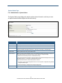
Document Revision Level
This section provides a history of the revision changes to this document.
Revision
A
Document Version
Version 1
Date
Description
08/05/2014
Initial release
Changes in this Revision
N/A - this is first version of this document.
iii
EX17082, EX17162, and EX17242 Web-Smart Switches User Guide
Document Conventions
This guide uses the following conventions to draw your attention to certain information.
Safety and Warnings
This guide uses the following symbols to draw your attention to certain information.
Symbol
Meaning
Description
Note
Notes emphasize or supplement important points of the main text.
Tip
Tips provide helpful information, guidelines, or suggestions for performing tasks more
effectively.
Warning
Warnings indicate that failure to take a specified action could result in damage to the
device, or could result in serious bodily injury.
Electric Shock Hazard
This symbol warns users of electric shock hazard. Failure to take appropriate precautions
such as not opening or touching hazardous areas of the equipment could result in injury or
death.
Typographic Conventions
This guide also uses the following typographic conventions.
Convention
Description
Bold
Indicates text on a window, other than the window title, including menus, menu options, buttons, fields, and labels.
Italic
Indicates a variable, which is a placeholder for actual text provided by the user or system. Angled brackets (< >) are
also used to indicate variables.
screen/code
Indicates text that is displayed on screen or entered by the user.
< > angled
brackets
Indicates a variable, which is a placeholder for actual text provided by the user or system. Italic font is also used to
indicate variables.
[ ] square
brackets
Indicates optional values.
{ } braces
Indicates required or expected values.
| vertical bar
Indicates that you have a choice between two or more options or arguments.
iv
EX17082, EX17162, and EX17242 Web-Smart Switches User Guide
References to Switch Models
This guide covers the EX17082, EX17162, and EX17242 Web-Smart Switches from EtherWAN
Systems, Inc. When information in this guide applies to both models, the models are referred to
collectively as “the switch.” If information applies to specific models only, those models are identified
by model name (EX17082, EX17162, or EX17242).
v
EX17082, EX17162, and EX17242 Web-Smart Switches User Guide
Contents
Preface ..................................................................................................................... iii
Changes in this Revision ............................................................................................. iii
Document Conventions ...............................................................................................iv
Safety and Warnings ...................................................................................................iv
Typographic Conventions ...........................................................................................iv
References to Switch Models ...................................................................................... v
Contents .................................................................................................................. vi
1 Introduction ........................................................................................................... 9
Key Features ............................................................................................................. 11
Model EX17082 Features.................................................................................... 11
Model EX17162 Features.................................................................................... 11
Model EX17242 Features.................................................................................... 11
Model EX17242L Features.................................................................................. 11
Common Features............................................................................................... 11
Quick Start Guide ...................................................................................................... 12
2 Unpacking and Installation ................................................................................ 14
Unpacking the Hardware ........................................................................................... 15
System Requirements ............................................................................................... 15
Hardware Features ................................................................................................... 16
Front Panel .......................................................................................................... 16
Rear Panel .......................................................................................................... 19
Side and Bottom Panels ...................................................................................... 19
Installing the Switch .................................................................................................. 20
Preparing the Site................................................................................................ 21
Installing the Switch............................................................................................. 21
Connecting to the 10/100 Mbps RJ-45 Ports ...................................................... 24
Connecting to the Gigabit Ethernet Ports ............................................................ 25
vi
EX17082, EX17162, and EX17242 Web-Smart Switches User Guide
Checking the Installation ..................................................................................... 26
Applying AC Power ............................................................................................. 26
Where to Go from Here ............................................................................................. 27
3 Preparing to Configure the Switch .................................................................... 28
Connecting the PC .................................................................................................... 29
Configuring TCP/IP Settings for Microsoft Windows 7 .............................................. 29
Disabling Proxy Settings ........................................................................................... 31
Disabling Proxy Settings in Internet Explorer ...................................................... 31
Disabling Proxy Settings in Firefox...................................................................... 32
Disabling Proxy Settings in Safari ....................................................................... 32
Disabling Firewall and Security Software .................................................................. 33
4 Configuring the Switch....................................................................................... 34
Logging in to the Web Management Interface .......................................................... 35
Idle Time Security ..................................................................................................... 36
Understanding the Web Management Interface ....................................................... 36
Web Management Interface Menus .......................................................................... 38
Administrator Menu ............................................................................................. 40
Port Management Menu ...................................................................................... 47
VLAN Setting Menu ............................................................................................. 57
Per Port Counter Menu ....................................................................................... 67
QoS Setting Menu ............................................................................................... 69
Security Menu ..................................................................................................... 74
Trunking Menu .................................................................................................... 79
Backup/Recovery Menu ...................................................................................... 82
Miscellaneous Menu............................................................................................ 85
Logout Menu ....................................................................................................... 88
5 Troubleshooting ................................................................................................. 89
Troubleshooting Chart ............................................................................................... 90
Additional Troubleshooting Suggestions ................................................................... 91
Network Adapter Cards ....................................................................................... 91
vii
EX17082, EX17162, and EX17242 Web-Smart Switches User Guide
Configuration ....................................................................................................... 91
Switch Integrity .................................................................................................... 91
Auto-Negotiation.................................................................................................. 91
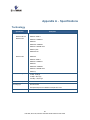
Technology ................................................................................................................ 92
Power ........................................................................................................................ 93
Mechanical ................................................................................................................ 93
Interface .................................................................................................................... 94
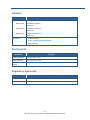
Environment .............................................................................................................. 94
Regulatory Approvals ................................................................................................ 94
Index ....................................................................................................................... 96
viii
EX17082, EX17162, and EX17242 Web-Smart Switches User Guide
1 Introduction
Congratulations on your purchase of the Web-Smart EX17082,
Topics:
EX17162, or EX17242 Switch from EtherWAN Systems, Inc. Your
Key Features (page 11)
Quick Start Guide (page
designed for users who require high-performance along with the
12)
power of management to eliminate bottlenecks and increase
switch is a state-of-the-art IEEE-compliant network solution
productivity.
Your switch is also a Power Sourcing Equipment (PSE) device. All
10/100 Mbps ports support Power over Ethernet (PoE), which
detects and supplies power with IEEE 802.3af-complaint powered
devices automatically. The switch also provides Gigabit-speed
connections to servers and other Gigabit Ethernet switches. To
simplify installation, the switch is shipped ready for use.
9
EX17082, EX17162, and EX17242 Web-Smart Switches User Guide
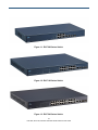
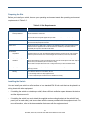
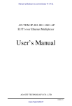
Figure 1-1. EX17082 Series Switch
Figure 1-2. EX17162 Series Switch
Figure 1-3. EX17242 Series Switch
10
EX17082, EX17162, and EX17242 Web-Smart Switches User Guide
Key Features
This section summarizes the key features of the EX17162 and EX17242 switches.
Model EX17082 Features
8 10/100TX ports supporting 15.4 W (IEEE 802.3af) Power over Ethernet (PoE) Power Sourcing
Equipment (PSE), with a total PoE power budget of 246.4 W Max.
Model EX17162 Features
16 10/100TX ports supporting 15.4 W (IEEE 802.3af) Power over Ethernet (PoE) Power Sourcing
Equipment (PSE), with a total PoE power budget of 246.4 W Max.
Model EX17242 Features
24 10/100TX ports supporting 15.4W (IEEE 802.3af) PoE PSE, with a total PoE power budget of
369.6 W Max.
Model EX17242L Features
24 10/100TX ports supporting 15.4W (IEEE 802.3af) PoE PSE, with a total PoE power budget of
180 W Max.
Common Features
Two pair of Gigabit Ethernet ports:
–
Two RJ-45 1000TX ports
–
Two fibre optic Small Form Factor Pluggable (SFP) 1000TX ports
All 10/100TX and 1000TX ports support full/half-duplex, auto-negotiation, and auto-MDI/MDIX
Web management interface for configuring PoE power status and link status, system, IP
configuration, port-based VLAN, QoS mode, QoS priority, and MAC/port-based trunking
100 – 240 VAC, 50 – 60 Hz internal universal power supply
0°C to 45°C (32°F to 113°F) operating temperature range
Supports rack mounting
11
EX17082, EX17162, and EX17242 Web-Smart Switches User Guide
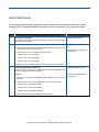
Quick Start Guide
The following procedure enables advanced users to get their switch up and running in the shortest
possible time. For detailed installation instructions, refer to the sections in the right column below.
Step
Description
For Reference, See…
1.
Find a Location for the Switch
“Preparing the Site” (page 21)
Set the switch on a flat surface or mount it in a standard rack (1 rack unit high) using the supplied
rack-mounting hardware brackets.
2.
Connect to the 10/100 Mbps Switch Ports
“10/100 Mbps RJ-45 Ports" (page 17)
Connect one end of a Category 5 or better Ethernet cable to the Ethernet port of a computer,
and
printer, network storage, or other network device.
Connect the other end to a 10/100 Mbps RJ-45 port on the switch:
“Connecting to the 10/100 Mbps RJ-45
Ports” (page 24)
Model EX17082: use ports 1 through 8.
Model EX17162: use ports 1 through 16.
Model EX17242: use ports 1 through 24.
Repeat this step for each additional device you want to connect to the 10/100 Mbps ports.
3.
Connect to the Gigabit Ethernet Switch Ports
“Gigabit Ethernet Ports” (page 17)
Connect to the same ports, either the two 1000 Mbps RJ-45 ports or the two fibre optic SFP ports.
You cannot use both pairs of ports at the same time.
RJ-45 Ports:
Connect one end of a Category 5 or better Ethernet cable to the Ethernet port of a device or
“Connecting to the Gigabit Ethernet
Ports” (page 24)
other switch.
Connect the other end to one of the 1000 Mbps RJ-45 ports on the front of the switch:
Model EX17082: use ports 9 TX and 10 TX.
Model EX17162: use ports 17 TX and 18 TX.
Model EX17242: use ports 25 TX and 26 TX.
Repeat this step to use the second 1000 Mbps RJ-45 port if necessary.
12
EX17082, EX17162, and EX17242 Web-Smart Switches User Guide
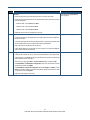
Step
Description
For Reference, See…
SFP Ports:
“Connecting to the Gigabit Ethernet
Ports” (page 24)
Remove any protector plugs from the SFP transceivers on the front of the switch.
Position and insert a SFP transceiver into one of the SFP ports until it is firmly seated, and then
close the latching bale.
Model EX17082: use ports 9FX through 10FX.
Model EX17162: use ports 17 FX and 18 FX.
Model EX17242: use ports 25 FX and 26 FX.
Repeat this step to use the second SFP port if necessary.
4.
Power On
“Applying AC Power” (page 26)
Connect the female end of the supplied AC power adapter cable to the power receptacle on
the back of the switch.
Connect the 3-pronged end of the AC power adapter cable to a grounded 3-pronged AC outlet.
Move the ON/OFF switch on the rear panel of the switch to the ON position.
Wait for the switch to complete its Power On Self Test.
Confirm that the LEDs for ports connected to a device are green. If not, replace the Ethernet
cable, and then check the port LED again.
5.
Configure the Switch
Chapters 3 and 4
Configure a PC for subnet 192.168.2.n, where n is a number other than 1 in the range 0 to 255.
Connect the PC to a 10/100 Mbps RJ-45 port on the switch, launch a browser, and specify the
switch’s default IP address 192.168.2.1.
At the User Log In page, type admin in the ID and Password fields, and then click OK.
Click Administrator > Authentication Configuration, enter a new case-sensitive username
and password, and then click Update.
Click Administrator > System IP Configuration. Next to IP Configure, click DHCP, or click
Static and enter the IP address, subnet mask, and gateway settings for the network on which
you will use the switch. Click Update.
Change any other settings, as necessary.
13
EX17082, EX17162, and EX17242 Web-Smart Switches User Guide
2 Unpacking and Installation
This chapter describes how to unpack and install the EX17082,
Topics:
Unpacking the Hardware
EX17162, and EX17242 switches.
(page 15)
System Requirements
(page 15)
Hardware Features (page
16)
Installing the Switch (page
20)
Where to Go from Here
(page 27)
14
EX17082, EX17162, and EX17242 Web-Smart Switches User Guide
Unpacking the Hardware
Unpack the items and confirm that no items are missing or damaged. Your package should include:
One EX17082, EX17162, or EX17242 switch
One external power adapter
Rack-mounting hardware brackets
One CD containing this user’s guide
If any item is damaged or missing, notify your authorized EtherWAN representative. Keep the carton,
including the original packing material, in case you need to store the product or return it.
System Requirements
To complete your installation, you need the following items:
Computer with an Ethernet (RJ-45) Interface
Managing the switch requires a personal or notebook computer (PC) with a 10/100base-TX
Ethernet interface and a physical RJ-45 connection. The preferred operating system for the
computer is Microsoft Windows XP/Vista/7. You can use Apple OSX or Linux systems as well, but
for brevity, all web configurations in this manual use Windows 7 as the underlying operating
system.
Category 5+ Ethernet Cables
An Ethernet cable of at least Category 5 rating is required to connect your PC to the switch. The
cable can be configured as "straight-through" or crossover.
Web Browser Software
Use any of the following web browsers when configuring the switch:
–
Internet Explorer
–
Mozilla Firefox
–
Google Chrome
Internet Explorer is the preferred browser for EtherWAN switch configuration.
15
EX17082, EX17162, and EX17242 Web-Smart Switches User Guide
Hardware Features
The following sections describe the hardware features of the EX17082, EX17162, and EX17242
switches.
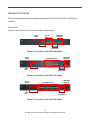
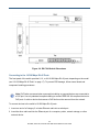
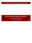
Front Panel
Figure 2-2 and Figure 2-3 show the front panels of the switches.
Reset
Button
10/100
Mbps Ports
Status LEDs
1000 Mbps
SFP Ports
1000 Mbps
RJ-45 Ports
Figure 2-1. Front Panel of the EX17082 Switch
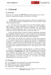
Reset
Button
Power
LED
1000 Mbps
SFP Ports
10/100 Mbps Ports
Status LEDs
1000 Mbps
RJ-45 Ports
Figure 2-2. Front Panel of the EX17162 Switch
Reset
Button
Power
LED
1000 Mbps
SFP Ports
10/100 Mbps Ports
Status LEDs
1000 Mbps
RJ-45 Ports
Figure 2-3. Front Panel of the EX17242 Switch
16
EX17082, EX17162, and EX17242 Web-Smart Switches User Guide
10/100 Mbps RJ-45 Ports
The switches have the following 10/100 Mbps RJ-45 ports:
Number of 10/100 Mbps RJ-45 Ports
Port Designations
Model EX17082
8
1 through 8 (see Figure 2-1)
Model EX17162
16
1 through 16 (see Figure 2-2)
Model EX17242
24
1 through 24 (see Figure 2-3)
Switch Model
These ports are auto-sensing, auto-MDIX 10/100 Mbps ports. When you insert a cable into an RJ-45
port, the switch:
Determines whether the cable is a straight-through or crossover cable.
Automatically ascertains the maximum speed (10 or 100 Mbps) and duplex mode (half- or
full-duplex) of the attached device.
After determining this information, the switch configures the RJ-45 port automatically to enable
communications with the attached device, without requiring user intervention.
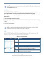
Gigabit Ethernet Ports
EX17082, EX17162, and EX17242 switches have four Gigabit Ethernet interfaces in the form of two
RJ-45 ports and two fibre optic Small Form Factor Pluggable (SFP) ports. These ports provide a
full-duplex 1000 Mbps (1 Gbps) connection, and can be used to connect upstream to other switches or
to other devices. For example, you can connect a Network Video Recorder (NVR) to one port, and use
the other port to upstream to another switch or the network backbone.
Table 2-1 shows the port designations for the Gigabit Ethernet interfaces. Only one pair of Gigabit
Ethernet ports can be used at a time. If you use one or two RJ-45 Gigabit Ethernet ports, for example,
you cannot use the SFP ports.
Table 2-1. Gigabit Ethernet Port Designations
Port Designations on 1000 Mbps RJ-45 Ports
Port Designations on SFP Ports
Model EX17082 (see Figure 2-1)
9 TX and 10 TX
9 FX and 10 FX
Model EX17162 (see Figure 2-2)
17 TX and 18 TX
17 FX and 18 FX
Model EX17242 (see Figure 2-3)
25 TX and 26 TX
25 FX and 26 FX
Switch Model
17
EX17082, EX17162, and EX17242 Web-Smart Switches User Guide
Note: These ports have also been referred to as mini-GigaBit or (GBIC) ports, but this term has
been made obsolete by SFP.
Reset Button
The EX17082, EX17162, and EX17242 front panels have a reset button to reset the switch to its
factory default settings. This button is recessed to prevent accidental resets of the switch.
To reset the switch to its factory default settings and remove all customized overrides you made to the
default settings:
1. Leave power cord connected to the switch.
2. Using a pin or paper clip, press and hold the reset button for about 10 seconds, then release the reset
button.
3. Wait for the switch to reboot.
Note: You can also reboot the switch using the Reboot Device page in the switch’s Web
management interface (see “Reboot Device Page” on page 46).
LEDs
The EX17082, EX17162, and EX17242 front panel LEDs show power, PoE, link/activity, and 1000
Mbps activity status. Table 2-2 summarizes the LEDs on the switches.
Table 2-2. Front Panel LEDs
LED
Color
Status
Description
Power
Yellow
ON
Power is supplied to the switch.
PoE
(the port number)
Yellow
ON
Power Device (PD) is connected.
OFF
PD is disconnected.
Link/ACT
(the port number)
Green
ON
A valid network connection has been established.
OFF
Data transmission is not occurring on the port.
Flashing
Data is being sent or received on the port.
ON
A valid network connection has been established on the 1000 Mbps port.
OFF
Data transmission is not occurring on the 1000 Mbps port.
Flashing
Data is being sent or received on the 1000 Mbps port.
1000M
(the port number)
Green
18
EX17082, EX17162, and EX17242 Web-Smart Switches User Guide
Rear Panel
The EX17082, EX17162, and EX17242 rear panels have a receptacle for connecting the supplied
external power adapter. Use only the external power adapter supplied with the switch.
The rear panels also have one or more fans that allow air to pass through the switch enclosure and
exit through the rear of the chassis. Be sure these fans are not blocked.
ON/OFF
Switch
Fan
Power
Receptacle
Figure 2-4. Rear Panel of the EX17082 Switch
Fan
Fan
ON/OFF
Switch
Power
Receptacle
Figure 2-5. Rear Panel of the EX17162 Switch
Fan
Fan
ON/OFF
Switch
Power
Receptacle
Figure 2-6. Rear Panel of the EX17242 Switch
Side and Bottom Panels
The EX17082, EX17162, and EX17242 side panels have vents for cooling. Be sure these vents are
not blocked.
The bottom panels have a product label that shows regulatory compliance, product serial number, and
other information.
19
EX17082, EX17162, and EX17242 Web-Smart Switches User Guide
Installing the Switch
Switch installation involves the following steps:
1.
Preparing the site. See page 21
2.
Installing the switch. See page 21.
3.
Connecting to the 10/100 Mbps RJ-45 ports. See page 24.
4.
Connecting to the Gigabit Ethernet ports. See page 25.
5.
Checking the installation. See page 26.
6.
Applying AC power. See page 26.
20
EX17082, EX17162, and EX17242 Web-Smart Switches User Guide
Preparing the Site
Before you install your switch, be sure your operating environment meets the operating environment
requirements in Table 2-3.
Table 2-3. Site Requirements
Characteristics
Requirements
Mounting
Desktop installations:
Provide a flat table or shelf surface.
Rack-mount installations:
Use a 19-inch (48.3-centimeter) EIA standard equipment rack that is grounded and physically secure. You
also need the rack-mount guide supplied with your switch.
Access
Locate the switch in a position that lets you access the front panel RJ-45 ports, view the front panel LEDs,
and access the rear-panel power connector.
Power source
Provide a power source within 6 feet (1.8 meters) of the installation location. Power specifications for the
switch are shown in Appendix A. Be sure the AC outlet is not controlled by a wall switch, which can
accidentally turn off power to the outlet and the switch.
Environmental
Temperature:
Install the switch in a dry area, with ambient temperature between 0 and 40ºC (32 and 104ºF). Keep the
switch away from heat sources such as direct sunlight, warm air exhausts, hot-air vents, and heaters.
Operating humidity:
The installation location should have a maximum relative humidity of 90%, non-condensing.
Ventilation:
Do not restrict airflow by covering or obstructing the vents on the rear and side panels of the switch. Keep at
least 2 inches (5.08 centimeters) free on all sides for cooling.
Be sure there is adequate airflow in the room or wiring closet where you intend to install the switch.
Operating conditions:
Keep the switch at least 6 ft (1.83 m) away from nearest source of electromagnetic noise, such as a
photocopy machine.
Stacking
If you intend to stack two or more switches, be sure:
The mounting surface can safely support the stack.
There is adequate space around the stack for ventilation and cooling.
Installing the Switch
You can install your switch on a flat surface or in a standard EIA 19-inch rack that can be placed in a
wiring closet with other equipment.
If installing the switch on a desktop or shelf, allow sufficient ventilation space between the device
and the objects around it.
If installing the switch in a rack, attach the supplied rack-mounting brackets to the switch's front
panel (one on each side), and secure them with the screws provided with the equipment rack. For
more information, refer to the documentation that came with the equipment rack.
21
EX17082, EX17162, and EX17242 Web-Smart Switches User Guide
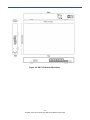
Figure 2-7. EX17082 Switch Dimensions
22
EX17082, EX17162, and EX17242 Web-Smart Switches User Guide
Figure 2-8. EX17162 Switch Dimensions
23
EX17082, EX17162, and EX17242 Web-Smart Switches User Guide
Figure 2-9. EX17242 Switch Dimensions
Connecting to the 10/100 Mbps RJ-45 Ports
The front panel of the switch provides 8, 16, or 24 10/100 Mbps RJ-45 ports, depending on the model
(see “10/100 Mbps RJ-45 Ports” on page 17). To prevent ESD damage, follow normal board and
component handling procedures.
Note: PoE faults are caused when noncompliant cabling or powered devices are connected to
a PoE port. Use only standard-compliant cabling to connect IEEE 802.3af-compliant devices to
PoE ports. A cable or device that causes a PoE fault must be removed from the network.
To connect devices to the switch’s 10/100 Mbps RJ-45 ports:
1. Insert one end of a Category 5 or better Ethernet cable into a switch port.
2. Insert the other cable end into the Ethernet port of a computer, printer, network storage, or other
network device.
24
EX17082, EX17162, and EX17242 Web-Smart Switches User Guide
3. Repeat steps 1 and 2 for each additional device you want to connect to the switch.
Connecting to the Gigabit Ethernet Ports
The front panel of the switch provides two 1000 Mbps RJ-45 ports and two 1000 Mbps fibre optic SFP
ports (see “Gigabit Ethernet Ports” on page 17). Use these ports to connect upstream to other
switches or to devices such as a storage unit or network video recorder (NVR).
The Gigabit ports are combination ports, where only one pair of ports can be used at a time. If you use
the RJ-45 interfaces on one port, for example, you cannot use the SFP on that same port.
Connecting to 1000 Mbps RJ-45 Ports
To connect devices to the 1000 Mbps RJ-45 ports:
1. Insert one end of a Category 5 or better Ethernet cable into either of the two 1000 Mbps RJ-45 ports
on the front panel of the switch.
2. Connect the other end of the cable to the other switch or device.
3. Repeat steps 1 and 2 to connect the second 1000 Mbps RJ-45 port to another switch or device.
Connecting to 1000 Mbps Fibre Optic SFP Ports
To connect devices to the 1000 Mbps fibre optic SFP ports:
1. Attach an ESD-preventive wrist strap to your wrist and to a bare metal surface on the chassis.
2. Remove the dust plugs from the fiber-optic SFP module ports on the switch and store them in a safe
place.
3. Find the send (TX) and receive (RX) markings that identify the top side of the SFP module.
Note: On some SFP modules, the send and receive (TX and RX) markings might be replaced
by arrows that show the direction of the connection, either send or receive (TX or RX). .
4. Align the SFP module in front of the slot opening.
5. Insert the SFP module into the slot on the switch until you feel the connector on the module snap into
place in the rear of the slot.
25
EX17082, EX17162, and EX17242 Web-Smart Switches User Guide
Checking the Installation
Before you apply power:
Inspect the equipment thoroughly.
Verify that all cables are installed correctly.
Check cable routing to make sure cables are not damaged or create a safety hazard.
Be sure all equipment is mounted properly and securely.
Applying AC Power
EX17082, EX17162, and EX17242 switches have an ON/OFF switch that controls power to the switch.
Before you connect the power cord, select an AC outlet that is not controlled by a wall switch, which
can turn off power to the switch. After you select an appropriate outlet, use the following procedure to
apply AC power.
1. Connect the female end of the supplied AC power adapter cable to the power receptacle on the back
of the switch.
2. Connect the 3-pronged end of the AC power adapter cable to a grounded 3-pronged AC outlet.
3. On the rear panel, move the ON/OFF switch to the ON position ( ).
When you apply power:
All green PoE, Link/ACT, and 100M LEDs blink momentarily.
The fans start.
The yellow Power LED goes ON.
The Link/ACT and 100M LEDs for every port connected to a device flash, as the switch conducts a
brief Power On Self-Test (POST).
After the switch passes the POST, the Link/ACT and 100M LEDs for every port connected to a device
go ON. The PoE LEDs also go ON if Power Devices are connected. The switch is now functional and
ready to pass data.
If you do not hear the fans, or if the Power LED is not ON, check that the power cable is plugged in
correctly, the ON/OFF switch is set to the ON position, and that the power source is good and not
controlled by a wall switch. If this does not resolve the problem, see Chapter 5, Troubleshooting.
26
EX17082, EX17162, and EX17242 Web-Smart Switches User Guide
Where to Go from Here
After you power-up the switch for the first time, you configure it using the switch’s built-in management
software. For more information, see Chapters 3 and 4.
27
EX17082, EX17162, and EX17242 Web-Smart Switches User Guide
3 Preparing to Configure the Switch
After you install the switch, configure it using the switch’s built-in
Topics:
Connecting the PC (page
For the Web browser to access the switch’s Web management
29)
interface, the PC and switch must be on the same subnet. This
Configuring TCP/IP
Settings for Microsoft
Windows 7 (page 29)
Disabling Proxy Settings
(page 31)
Web management interface and a Web browser on a PC.
means the first time you configure the switch, you must change
your PC’s TCP/IP settings to match the switch’s default subnet of
192.168.2.1.
The procedure for changing your PC’s TCP/IP settings depends
on the PC’s operating system. This chapter describes how to
Disabling Firewall and
configure TCP/IP settings for PCs that have a Microsoft Windows
Security Software (page
7 operating system.
33)
If your PC is running an operating system other than Windows 7,
refer to the documentation for your operating system to find out
how to change the PC’s TCP/IP settings.
28
EX17082, EX17162, and EX17242 Web-Smart Switches User Guide
Connecting the PC
To connect a PC to the switch:
1. Insert one end of a Category 5 or better Ethernet cable into an available 10/100 Mbps RJ-45 port on
the front panel of the switch.
2. Connect the other end of the cable to the Ethernet port on the PC you will use to configure the
switch.
3. Confirm that the Link/ACT LED for the port to which the PC is connected is ON. If the LED is OFF,
replace the Ethernet cable connecting your computer and switch.
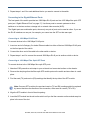
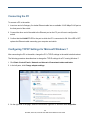
Configuring TCP/IP Settings for Microsoft Windows 7
After connecting the PC to the switch, change the PC’s TCP/IP settings to the switch’s default subnet.
The following procedure describes how to change the TCP/IP settings for a PC running Windows 7.
1. Click Start >Control Panel > Network and Internet >View network status and tasks.
2. In the left pane, click Change adapter settings.
3. On the right side of the page, select the connection, right click it, and then select Properties.
29
EX17082, EX17162, and EX17242 Web-Smart Switches User Guide
4. Click Internet Protocol Version 4 (TCP/IPv4), and then click Properties.
5. In the General tab, click Use the following IP address.
6. In the IP address field, type 192.168.2.10.
Tip: Although the last digit in the previous step is 10, in reality, this digit can be any number
between 0 and 255, except the number 1 because the address 192.168.2.1 is already being
used by the switch.
7. Press the Tab key to populate the Subnet mask field automatically. You can leave the Default
gateway field blank.
30
EX17082, EX17162, and EX17242 Web-Smart Switches User Guide
8. Click OK to exit the current dialog box, and then click OK again to exit the initial dialog box.
Disabling Proxy Settings
Before using the switch’s Web management interface, disable proxy settings in your Web browser.
Otherwise, you might not be able to view the switch’s Web-based configuration pages.
Disabling Proxy Settings in Internet Explorer
The following procedure describes how to disable proxy settings in Internet Explorer 5 and later.
1.
Start Internet Explorer.
2.
On your browser’s Tool menu, click Options. The Internet Options dialog box appears.
3.
In the Internet Options dialog box, click the Connections tab.
4.
In the Connections tab, click the LAN settings button. The Local Area Network (LAN) Settings
dialog box appears.
5.
In the Local Area Network (LAN) Settings dialog box, uncheck all check boxes.
6.
Click OK until the Internet Options window appears.
7.
In the Internet Options window, under Temporary Internet Files, click Settings.
8.
For the option Check for newer versions of stored pages, select Every time I visit the webpage.
31
EX17082, EX17162, and EX17242 Web-Smart Switches User Guide
9.
Click OK until you close all open browser dialog boxes.
Disabling Proxy Settings in Firefox
The following procedure describes how to disable proxy settings in Firefox.
1.
Start Firefox.
2.
On your browser’s Tools menu, click Options. The Options dialog box appears.
3.
Click the Advanced tab.
4.
In the Advanced tab, click the Network tab.
5.
Click the Settings button.
6.
Click Direct connection to the Internet.
7.
Click the OK button to confirm this change.
Disabling Proxy Settings in Safari
The following procedure describes how to disable proxy settings in Safari.
1.
Start Safari.
2.
Click the Safari menu and select Preferences.
3.
Click the Advanced tab.
4.
In the Advanced tab, click the Change Settings button.
5.
Choose your location from the Location list (this is generally Automatic).
6.
Select your connection method. If using a wired connection, select Built-in Ethernet. For wireless,
select Airport.
7.
Click the Proxies tab.
8.
Be sure each proxy in the list is unchecked.
9.
Click Apply Now to finish.
32
EX17082, EX17162, and EX17242 Web-Smart Switches User Guide
Disabling Firewall and Security Software
If you encounter problems connecting to the switch, disable any firewall or security software that may
be running on your PC before configuring the switch. For more information, refer to the documentation
for your firewall.
33
EX17082, EX17162, and EX17242 Web-Smart Switches User Guide
4 Configuring the Switch
Topics:
Logging in to the Web
Management Interface
(page 35)
Idle Time Security (page
36)
Understanding the Web
Management Interface
(page 36)
Web Management
Interface Menus (page
38)
After you attach a PC to the switch and configure the PC to
the same subnet as the switch, use the information in this
chapter to configure the switch.
34
EX17082, EX17162, and EX17242 Web-Smart Switches User Guide
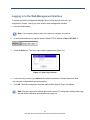
Logging in to the Web Management Interface
To access the switch’s configuration settings, launch a Web browser on the PC you
configured in Chapter 3 and log in to the switch’s Web management interface.
1.
Launch a Web browser.
Note: Your computer does not have to be online to configure your switch.
2.
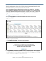
In the browser address bar, type the switch’s default TCP/IP address of http://192.168.2.1:
3.
Press the Enter key. The User Log In screen appears (see Figure 4-1).
Figure 4-1. User Log In Screen
4.
5.
In the User Log In screen, type admin as the default username and default password. Both
the username and password are case sensitive.
Click OK. The Web management interface starts and the page in Figure 4-2 appears.
Note: First-time logins must change the switch’s system IP configuration settings (see page
42) and default username and password (see page 41).
35
EX17082, EX17162, and EX17242 Web-Smart Switches User Guide
Idle Time Security
For security, the switch has an idle time security feature that either closes the current Web
management session automatically or displays the last management page accessed if the
interface is not used for a certain period of time.
By default, this feature is disabled. However, you can use the System Status page to enable
this feature and configure the period of inactivity that can occur during a Web management
session before the switch ends the session automatically. For more information, see “System
Status Page” on page 43.
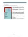
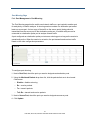
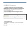
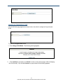
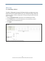
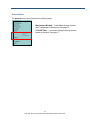
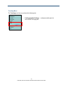
Understanding the Web Management Interface
The top of the Web management interface shows the switch ports, with ports in use
highlighted in green. In Figure 4-2, for example, the ports for the EX17162 switch are shown,
with port 4 in use.
The left side of the Web management interface contains the menus you use to configure the
switch. When you click a menu, the configuration settings associated with the menu appear in
the workspace (see Figure 4-2). The menus and configuration settings for the EX17162 and
EX17242 switches are the same.
Switch Ports
(green = ports in use)
Menus
Workspace
Figure 4-2. Main Areas on the Web Management Interface (EX17162 Switch)
36
EX17082, EX17162, and EX17242 Web-Smart Switches User Guide
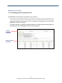
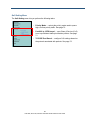
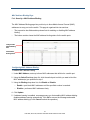
Some menus have submenus. If you click a menu that has submenus, the submenus appear
below it. For example, if you click the Administrator menu, the submenus in Figure 4-3
appear.
Figure 4-3. Example of Administrator Submenus
Note: Depending on the switch model you have, the number of ports shown in the screens in
this chapter might differ from the number of ports shown in your Web management screens.
37
EX17082, EX17162, and EX17242 Web-Smart Switches User Guide
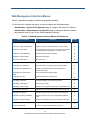
Web Management Interface Menus
Table 4-1 describes the pages in the Web management interface.
The first time you configure the switch, you must configure the following settings:
Administrator > System IP Configuration page to configure the switch’s IP address.
Administrator > Authentication Configuration page to change the default username
and password used to log in to the Web management interface.
Table 4-1. Web Management Interface Menus and Submenus
Menus and Submenus
Description
See Page
Administrator > Authentication Configuration
Changes the Web management interface username and password.
41
Administrator > System IP Configuration
Configures the switch to use a DHCP-assigned or static IP address.
42
Administrator > System Status
Shows the MAC address, number of ports, and system version; and lets
you specify idle time security settings and an optional comment.
43
Administrator > Load default setting
Returns the switch to its default configuration.
43
Administrator > Firmware Update
Updates the switch firmware.
45
Administrator > Reboot Device
Reboots the switch.
46
Port Management > Port Configuration
Configures switch ports.
48
Port Management > Port Mirroring
Sends network traffic on a port copied to another port for analysis.
51
Port Management > Bandwidth Control
Limits the rates at which the switch accepts incoming data and
retransmits outgoing data.
52
Port Management > Broadcast Storm
Control
Prevents network traffic from being disrupted.
55
Port Management > POE
Enables or disables PoE for each switch port.
56
VLAN Setting > VLAN Mode
Toggles between tagged- and port-based VLAN modes.
59
VLAN Setting > VLAN Member
Allows ports to join a VLAN.
63
VLAN Setting > Multi to 1 Setting
Configures one or more physical switch ports to a single destination port.
66
Per Port Counter > Port Counter
Displays the number of packets transmitted and received for each port.
68
QoS Setting > Priority Mode
Selects the priority mode used to queue high- and low-priority traffic.
70
QoS Setting > Port 802.1p, IP/DS Based
Uses Class of Service (CoS) to set up consistent traffic prioritization
policies.
71
QoS Setting > TCP/UDP Port Based
Configure CoS settings based on the protocol associated with packets.
72
Security > MAC Address Binding
Binds Media Access Channel (MAC) addresses to switch ports.
75
Security > TCP/UDP Filter
Processes or drops incoming packets based on protocols.
77
38
EX17082, EX17162, and EX17242 Web-Smart Switches User Guide
Table 4-1. Web Management Interface Menus and Submenus
Menus and Submenus
Description
See Page
Trunking > Link Aggregation Settings
Configures switch ports for use in trunks.
80
Backup/Recovery
Saves and restores the switch configuration.
83
Miscellaneous
Configures output queuing aging time, VLAN striding, IGMP snooping
versions 1 and 2, and VLAN uplink setting.
86
Logout
Logs you out of the current Web management interface session.
88
39
EX17082, EX17162, and EX17242 Web-Smart Switches User Guide
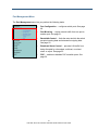
Administrator Menu
The Administrator menu lets you perform the following tasks:
Authentication Configuration changes the
username and password used to log in to the Web
management interface. See page 41.
System IP Configuration configures the switch
to use a DHCP-assigned or static IP address. See
page 42.
System Status shows the MAC address, number
of ports, and system version. Also, lets you specify
idle time security settings and an optional comment.
See page 43.
Local default settings returns the switch to its
default configuration. See page 43.
Firmware Update updates the switch firmware.
See page 45.
Reboot Device reboots the switch. See page 46.
40
EX17082, EX17162, and EX17242 Web-Smart Switches User Guide
Authentication Configuration Page
Path: Administrator > Authentication Configuration
The Authentication Configuration page lets you change the username and password used to
log in to the switch’s Web management interface.
The first time you log in, we recommend you change the default username and password
used to log in to the switch’s Web management interface to prevent unauthorized individuals
from gaining access to the switch.
1. In the Username field, enter a case-sensitive username, up to 15 characters. Permitted
characters are lower-case characters a-z, upper-case characters A-Z, digits 0-9,
underscore (_), plus sign (+), minus sign (-), and equals sign (=).
2. In the Password field, enter a case-sensitive password, up to 15 characters. Permitted
characters are the same as the ones for the username 1. For security, each typed
password character is masked as a dot (•).
3. In the Confirm field, enter the same case-sensitive password you typed in the Password
field. For security purposes, every typed character is masked as a dot ().
4. Click Update.
5. When a message tells you that the update was successful and prompts you to reboot the
switch, click Reboot.
41
EX17082, EX17162, and EX17242 Web-Smart Switches User Guide
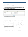
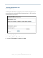
System IP Configuration Page
Path: Administrator > System IP Configuration
The System IP Configuration page lets you configure the switch to use a static or dynamic
(DHCP) IP address. The first time you log in, configure these settings to match the settings of
the network on which the switch will be used.
1. If your network uses a Dynamic Host Configuration Protocol (DHCP) server to allocate IP
addresses dynamically, next to IP Configure, click DHCP, and then skip to step 3.
2. If your network uses static IP addresses, next to IP Configure, click Static. Then complete
the IP Address, Subnet Mask, and Gateway fields with the static IP address information
for the switch. The IP address must be unique and must not be used by any other device on
the network.
3. Click Update.
42
EX17082, EX17162, and EX17242 Web-Smart Switches User Guide
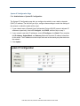
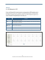
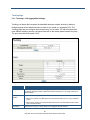
System Status Page
Path: Administrator > System Status
The System Status page displays the switch’s system status information, and lets you enter
an optional comment and configure the idle time security.
Field
Description
MAC Address
Read-only field that shows the switch’s Media Access Channel (MAC) address.
Number of Ports
Read-only field that shows the number of ports on the switch.
Comment
Lets you enter an optional comment, up to 15 characters. Permitted characters are lower-case characters a-z,
upper-case characters A-Z, digits 0-9, underscore (_), plus sign (+), minus sign (-), and equals sign (=).
System Version
Read-only field that shows the system software version.
Idle Time Security
Number of minutes a Web management session can be idle before the switch ends the session or displays the
last management page shown. By default, idle time security is disabled. To change this setting:
1. Check the Idle Time Security check box to enable idle time security.
2. In the Idle Time field, enter the number of minutes the switch can remain idle before taking the action in step 3
automatically. Range is 1-to-30 minutes. 0 disables idle timeout security.
3. Click the action the switch is to take when the idle time is reached:
Auto logout = log out of current management session. The user is required to re-login before using the Web
management interface again.
Back to the last display = redisplay the last management page shown.
Update Button
After configuring the settings on this page, click this button to commit your settings.
43
EX17082, EX17162, and EX17242 Web-Smart Switches User Guide
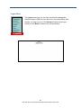
Load Default Setting Page
Path: Administrator > Load Default Setting
The Load Default Setting page provides a Load button that returns the switch to its default
configuration settings. Clicking this button removes all overrides made to the default
configuration settings.
The only settings that do not return to their default settings are:
The switch’s IP address
The comment entered in the Administrator > System Status page
The username and password configured in the Administrator > Authentication
Configuration page.
To reset the switch’s IP address, comment, and username and password, reset the switch
using the reset button (see “Reset Button” on page 18).
44
EX17082, EX17162, and EX17242 Web-Smart Switches User Guide
Firmware Update Page
Path: Administrator > Firmware Update
The Firmware Update page lets you upgrade the switch firmware. After you obtain the
upgraded firmware file from EtherWAN, use the fields in this page to upgrade the switch
firmware.
1. In the Password field, enter the case-sensitive password used to access the Web
management interface. For security, each typed password character is masked as a dot (•).
2. In the ReConfirm, field, enter the same case-sensitive password you typed in the
Password field. For security purposes, every typed character is masked as a dot (•).
3. Click Update. A warning message appears.
4. Click OK to proceed with the firmware update (or click Cancel to abort the procedure).
45
EX17082, EX17162, and EX17242 Web-Smart Switches User Guide
Reboot Device Page
Path: Administrator > Reboot Device
The Reboot Device page has a Confirm button that reboots the switch. This button is
functionally equivalent to pressing the reset button on the switch (see “Reset Button” on page
18).
46
EX17082, EX17162, and EX17242 Web-Smart Switches User Guide
Port Management Menu
The Port Management menu lets you perform the following tasks:
Port Configuration configures switch ports. See page
48.
Port Mirroring copies network traffic from one port to
another port. See page 51.
Bandwidth Control limits the rates at which the switch
accepts incoming data and retransmits outgoing data.
See page 52.
Broadcast Storm Control prevents LAN traffic from
being disrupted by a broadcast, multicast, or unicast
storm on a port. See page 55.
POE enables or disables PoE on switch ports. See
page 56.
47
EX17082, EX17162, and EX17242 Web-Smart Switches User Guide
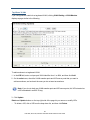
Port Configuration Page
Path: Port Management > Port Configuration
The Port Management page is organized into two sections:
The top section provides drop-down lists and check boxes for configuring switch ports.
See “Configuring Switch Ports” on page 49.
The bottom section is a read-only area that shows the current status and settings of the
switch ports. See “Port Configuration Fields” on page 50.
Configure Switch
Ports Here
Current Status and
Settings
48
EX17082, EX17162, and EX17242 Web-Smart Switches User Guide
Configuring Switch Ports
To configure switch ports.
1. At the top of the page, next to Select Port No., check each switch port that will have the
same configuration settings.
2. Using the Function drop-down lists, set the configuration settings for the checked ports
(see Table 4-2).
3. Click Update.
Table 4-2. Port Configuration Settings
Setting
Tx/Rx Ability
Description
Enables or disables a port’s ability to send and receive data on the network. Choices are:
Enable = port can send and receive data.
Disable = port cannot send and receive data.
Auto-Negotiation
Enables or disables a port’s ability to negotiate the communication speed and duplex mode
automatically. Choices are:
Enable = port can auto-negotiate speed and duplex mode.
Disable = port cannot auto-negotiate speed and duplex mode.
Speed
Specifies the maximum speed for a port. Choices are:
1G = maximum port speed is 1 Gbps.
100M = maximum port speed is 100 Mbps.
10M = maximum port speed is 10 Mbps.
Duplex
Specifies the port’s duplex mode. Choices are:
Full = full-duplex.
Half = half-duplex.
Pause
Determines whether the port sends pause frames. When a port gets overloaded, enabling this
setting allows a port to send pause requests to the devices sending it data to allow the
overloaded condition to clear. Choices are:
Enable = send pause frames.
Disable = do not send pause frames.
Backpressure
Enables or disables backpressure on ports operating at 10 or 100 Mbps in half-duplex. During
periods of packet congestion, ports use backpressure to stop their network counterparts from
transmitting more packets temporarily. This prevents a buffer overrun, and the subsequent
loss and retransmission of network packets. You cannot set backpressure on ports where
auto-negotiation is enabled. You can enable backpressure only on ports where the speed and
duplex mode are configured manually. Choices are:
Enable = enable backpressure.
Disable = disable backpressure.
49
EX17082, EX17162, and EX17242 Web-Smart Switches User Guide
Setting
Addr. Learning
Description
Allows the switch to learn the MAC addresses of the stations in the network to identify on which
port to send traffic. Choices are:
Enable = enable address learning.
Disable = disable address learning.
Port Configuration Fields
The fields at the bottom area of the Port Configuration page show the current status and
setting status of the switch ports.
Field
Port
Description
Port numbers for each switch port.
Current Status
Link
Speed at which the port tries to connect to a port on another switch or device. A green LED
indicates ports in use.
Speed
Speed of the port (for example, “10” for 10 Mbps and “100” for 100 Mbps).
Duplex
Duplex mode of the port (for example, “FULL” for full-duplex).
FlowCtrl
Shows whether flow control is enabled (ON) or disabled (OFF) for the ports.
Setting Status
Tx/Rx Ability
Shows whether the port is configured to send and receive data.
Auto-Nego
Shows whether auto-negotiation is enabled or disabled for the ports.
Speed
Specifies the port speed.
Duplex
Shows the port duplex mode, either HALF (half-duplex) or FULL (full-duplex).
Pause
Shows whether the use of pause frames is enabled (ON) or disabled (OFF) for the ports.
Backpressure
Shows whether backpressure is enabled (ON) or disabled (OFF) for the ports.
Addr. Learning
Shows whether address learning is enabled (ON) or disabled (OFF) for the ports.
50
EX17082, EX17162, and EX17242 Web-Smart Switches User Guide
Port Mirroring Page
Path: Port Management > Port Mirroring
The Port Mirroring page lets the switch send network traffic on a port copied to another port
for analysis by a network analyzer. A mirroring session consists of a destination port and at
least one source port. A mirror copy of the traffic on the source port(s) being probed is
transmitted from the source port to the destination probe port. A network analyzer can be
connected to a destination probe port to analyze network traffic.
A port configured as a destination probe port acts as a mirroring port as long as the session is
operationally active. When the session is not active, the port transmits and receives traffic
based on the other configuration parameters.
To configure port mirroring:
1. Next to Dest Port, check the ports you want to designate as destination ports.
2. Using the Monitored Packets drop-down list, click the packets that are to be mirrored.
Choices are:
–
Disable = disables mirroring.
–
Rx = receive packets.
–
Tx = transmit packets.
–
Tx & Rx = transmit and receive packets.
3. Next to Source Port, check the ports you want to designate as source ports.
4. Click Update.
51
EX17082, EX17162, and EX17242 Web-Smart Switches User Guide
Bandwidth Control Page
Path: Port Management > Bandwidth Control
The Bandwidth Control page is organized into two sections:
The top section provides drop-down lists and fields for limiting the rate at which the switch
accepts incoming data and the rate at which it retransmits outgoing data. See “Configuring
Bandwidth Control” on page 53.
The bottom section is a read-only area that shows the current status and setting status of
the switch ports. See “Bandwidth Control Fields” on page 54.
Configure
Bandwidth
Control Here
Switch Port Status
and Settings
52
EX17082, EX17162, and EX17242 Web-Smart Switches User Guide
Configuring Bandwidth Control
To configure bandwidth control.
1. Using the Port No. drop-down list, click the switch port you want to configure.
2. In the Tx Rate field, enter a transmission rate from 0 to 255 (0 = full speed).
3. In the Rx Rate field, enter a receive rate from 0 to 255 (0 = full speed).
4. Using the Speed Base drop-down list, select Low or High, as follows:
–
–
Low:
32 Kbps Tx/Rx bandwidth resolution for ports 1 through 18.
Actual Tx/Rx bandwidth = rate value x 32 kbps. The rate value is 1~255.
High:
(1) 256 Kbps Tx/Rx bandwidth resolution for ports 1 through 16.
Actual Tx/Rx bandwidth = rate value x 256 Kbps. If link speed is 10 Mbps, the rate
value is 1~255. The rate value is 1~39.
(2) Bandwidth is 2048 Kbps for ports 17 and 18.
Actual Tx/Rx bandwidth = rate value x 2048Kbps. The rate value is 1~255.
If link speed is 10 Mbps, the rate value is 1~4.
If link speed is 100 Mbps, the rate value is 1~48.
5. Click Update (or click Load Default to load default values instead).
Note: If the link speed of the selected port is lower than the rate you set, the switch uses the
link speed value as your setting rate.
53
EX17082, EX17162, and EX17242 Web-Smart Switches User Guide
Bandwidth Control Fields
The fields at the bottom area of the Bandwidth Control page are two columns that show the
current status of the switch ports.
Field
Port No.
Description
Port numbers for each switch port.
Current Status
Tx Rate
Port transmission speed.
Rx Rate
Port receive speed.
Link Speed
Port link speed.
54
EX17082, EX17162, and EX17242 Web-Smart Switches User Guide
Broadcast Storm Control Page
Path: Port Management > Broadcast Storm Control
The Broadcast Storm Control page prevents traffic on a LAN from being disrupted by a
broadcast, multicast, or unicast storm on a port. A LAN storm occurs when packets flood the
LAN, creating excessive traffic and degrading network performance. Errors in the
protocol-stack implementation, mistakes in network configuration, or users issuing a
denial-of-service attack can cause a storm.
Storm control uses rising and falling thresholds to block and restore the forwarding of
broadcast, unicast, or multicast packets. Storm control is configured for the switch as a whole,
but operates on a per-port basis.
To configure broadcast storm control:
1. In the Threshold field, enter a number from 1 to 63 that corresponds to the number of
broadcast packets allowed to enter each port. A higher threshold allows more packets to
pass through.
2. Next to Enable Port, check each port to which you want to apply broadcast storm control.
3. Click Update.
55
EX17082, EX17162, and EX17242 Web-Smart Switches User Guide
POE Page
Path: Port Management > POE
Power over Ethernet (PoE) means that power sourcing equipment (PSE) supplies power to
powered devices (PD) such as IP telephone, wireless LAN access point, and web camera
from Ethernet interfaces through twisted pair cables. The POE Configuration page lets you
enable or disable PoE independently for each switch port.
Field
Description
Port
Port number for each port on the switch.
Enable
Check this check box to enable PoE for a port or uncheck to disable PoE for a port. If checked, the PoE of the port is
able to supply power to the attached PD.
PSE Current
Status of the port current.
Minimum Output
Power
Status of the minimum output power.
POE Class
Each POE port detects the class of the attached PD.
Update Button
After configuring the settings on this page, click this button to commit your settings.
56
EX17082, EX17162, and EX17242 Web-Smart Switches User Guide
VLAN Setting Menu
A Local Area Network (LAN) can be defined as a broadcast domain. Hubs, bridges or
switches in the same physical segment or segments connect all end node devices. End
nodes can communicate with each other without the need for a router. Routers connect LANs
together, routing the traffic to appropriate port.
A virtual LAN (VLAN) is a local-area network with a definition that maps workstations on
some other basis than geographic location (for example, by department, type of user, or
primary application). To communicate between VLANs, traffic must go through a router, just
as if they were on two separate LANs.
A VLAN is a group of PCs, servers and other network resources that behave as if they were
connected to a single, network segment — even though they may not be. For example, all
marketing personnel may be spread throughout a building. Yet if they are all assigned to a
single VLAN, they can share resources and bandwidth as if they were connected to the same
segment. The resources of other departments can be invisible to the marketing VLAN
members, accessible to all, or accessible only to specified individuals, depending on how the
IT manager has set up the VLANs.
The Advantages of VLANs
Provides network segmentation. Users who communicate most frequently with each
other can be grouped into common VLANs, regardless of physical location. Each group's
traffic is largely contained within the VLAN, reducing extraneous traffic and improving the
efficiency of the whole network.
Improves management. The addition of nodes, as well as moves and other changes,
can be dealt with quickly and conveniently from a management interface rather than the
wiring closet.
Increases bandwidth and performance. VLANs free up bandwidth by limiting
node-to-node and broadcast traffic throughout the network.
Enhances network security. VLANs create virtual boundaries that can be crossed only
through a router. So standard, router-based security measures can be used to restrict
access to each VLAN.
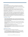
VLAN Behavior in the Switch
Packets received by the switch will be treated in the following way:
If an untagged packet enters a port configured for tag-based VLAN, the port settings
defined on the VLAN Setting > VLAN Mode page determine whether the packet is
tagged automatically. Each port has a default VLAN ID setting that is user-configurable.
The VLAN ID for each port can be changed on the VLAN Mode page.
57
EX17082, EX17162, and EX17242 Web-Smart Switches User Guide
If a tagged packet enters a port configured for tag-based VLAN, the port settings defined
on the VLAN Setting > VLAN Mode page determine whether the is tag is ignored or
removed automatically.
If the port in which the packet entered the switch does not have membership with the
VLAN specified by the VLAN ID tag, the packet is dropped. Port VLAN membership
settings are changed on the VLAN Setting > VLAN Member page.
If the port has membership to the VLAN specified by the packet’s VLAN ID, the packet will
be able to be sent to other ports with the same VLAN ID membership.
Packets leaving the switch will be either tagged or untagged, depending on the setting for
that port’s VLAN membership properties.
The switch’s VLAN features can be accessed from the VLAN Setting menu. This menu lets
you perform the following tasks:
VLAN mode toggles between tagged- and port-based
VLAN modes. See page 59.
VLAN Member allows ports to join a VLAN. See page 63.
Multi to 1 Setting configures one or more physical
switch ports to a single destination port. See page 66.
58
EX17082, EX17162, and EX17242 Web-Smart Switches User Guide
VLAN Mode Page
Path: VLAN Setting > VLAN Mode
The VLAN Mode page lets you toggle between two virtual VLAN modes:
Port-based VLAN
Tagged-based VLAN
Port-based VLANs
A port-based VLAN is a group of ports that form a logical Ethernet segment. Each port of a
port-based VLAN can belong to only one VLAN at a time. A port-based VLAN can have as
many or as few ports as needed. The VLAN can consist of all the ports on an Ethernet switch,
or just a few ports. In addition, a port-based VLAN can span switches and consist of ports
from multiple Ethernet switches.
Ports in a port-based VLAN are referred to as untagged ports and the frames received on the
ports as untagged frames. The names derive from the fact that the frames received on a port
do not contain any information that indicates VLAN membership, and that VLAN membership
is determined solely by a port’s PVID.
Tagged-based VLANs
VLAN membership in a tagged-based VLAN is determined by information within the frames
that are received on a port. This differs from a port-based VLAN, where the PVIDs assigned
to the ports determine VLAN membership.
The VLAN information within an Ethernet frame is referred to as a tag or tagged header. A
tag, which follows the source and destination addresses in a frame, contains the VID of the
VLAN to which the frame belongs (IEEE 802.3ac standard). This number uniquely identifies
each VLAN in a network.
59
EX17082, EX17162, and EX17242 Web-Smart Switches User Guide
When the switch receives a frame with a VLAN tag, referred to as a tagged frame, the switch
forwards the frame only to those ports that share the same VID.
A port that receives or transmits tagged frames is referred to as a tagged port. Any network
device connected to a tagged port must be IEEE 802.1Q-compliant. This is the standard that
outlines the requirements and standards for tagging. The device must be able to process the
tagged information on received frames and add tagged information to transmitted frames.
Changing to a Port-Based VLAN
If a VLAN Mode page similar to the following appears, the switch is configured for
tagged-based VLAN.
To switch to a port-based VLAN:
1. Click Change VLAN Mode. The following warning appears.
2.
Click Continue to proceed (or click Back to return to the previous page, without changing
the VLAN mode). If you clicked Continue, a page similar to the following appears, indicating
that the switch is now configured for a port-based VLAN.
60
EX17082, EX17162, and EX17242 Web-Smart Switches User Guide
Changing to a Tagged-Based VLAN
If the VLAN Mode page appears as shown below, the switch is configured for port-based
VLAN.
To switch to a tagged-based VLAN:
1. Click Change VLAN Mode. The following warning appears.
2.
Click Continue to proceed (or click Back to return to the previous page, without changing
the VLAN mode). If you clicked Continue, a page similar to the following appears.
61
EX17082, EX17162, and EX17242 Web-Smart Switches User Guide
3.
Next to Tag Mode, click whether the ports should add, ignore, or remove tags in the frames
they forward to other nodes on the network.
4. Click Update.
62
EX17082, EX17162, and EX17242 Web-Smart Switches User Guide
VLAN Member Page
Path: VLAN Setting > VLAN Member
You configure a port to belong to a VLAN by assigning a membership mode that determines
the kind of traffic the port carries and the number of VLANs to which it can belong. The
procedure you use depends on whether you configured the switch for port-based VLAN or
tagged-based VLAN (see “VLAN Mode Page” on page 59).
Port-Based VLANs
If you configured the switch for a port-based VLAN, clicking VLAN Setting > VLAN Member
displays a page similar to the following.
To add members to a port-based VLAN:
1. Using the Port drop-down list, select a port number, and then click Read.
2. On the select rows, check each destination port that you want to make a member of this
VLAN. Uncheck each port that you do not want to make a member.
3. Click Update (or click Load Default to load default values instead).
The VLAN Member table at the bottom of the page shows read-only settings for the VLAN
members associated with each switch port.
63
EX17082, EX17162, and EX17242 Web-Smart Switches User Guide
Tag-Based VLANs
If you configured the switch for a tag-based VLAN, clicking VLAN Setting > VLAN Member
displays a page similar to the following.
To add members to a tag-based VLAN:
1. In the VID field, enter a unique port VLAN identifier from 1 to 4094, and then click Add.
2. On the select rows, check the VLAN member ports and VID source ports that you want to
add as members, and uncheck the ones you do not want as members.
Note: If you do not check any VLAN member ports and VID source ports, this VID is treated as
a VID embedded in an 802.1Q tag.
3. Click Update.
Delete and Update buttons on the top-right side of the page let you remove or modify VIDs.
To delete a VID, click a VID from the drop-down list, and then click Delete.
64
EX17082, EX17162, and EX17242 Web-Smart Switches User Guide
To modify a VID, click a VID from the drop-down list, check or uncheck the VLAN member
ports and VID source ports as desired, and then click Update.
A map of the port VIDs appears at the bottom of the page.
65
EX17082, EX17162, and EX17242 Web-Smart Switches User Guide
Multi to 1 Page
Path: VLAN Setting > Multi to 1
The Multi to 1 Setting page is a per-port VLAN feature that lets you configure one or more
physical switch ports to a single destination port. If you configure this setting, it deletes the
VLAN group settings. Similarly, configuring the VLAN group settings thereafter deletes the
Multi-to-1 settings.
1. Using the Destination Port No. drop-down list, click a destination port number.
2. On the Disable Port row, check each physical port on the switch that you want to
exchange packets with the destination port.
3. Click Update.
66
EX17082, EX17162, and EX17242 Web-Smart Switches User Guide
Per Port Counter Menu
The Per Port Counter menu lets you perform the following task:
Port Counter displays the number of packets transmitted
and received for each port. See page 68.
67
EX17082, EX17162, and EX17242 Web-Smart Switches User Guide
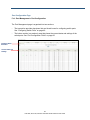
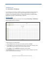
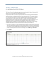
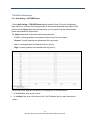
Port Counter Page
Path: Per Port Counter > Port Counter
The Counter Category page displays the number of packets transmitted and received for
each port.
1. Using the Counter Mode Selection drop-down list, click the type of packet you want to
view. Choices are:
–
Transmit and receive packets
–
Collision count and transmission packets
–
Dropped packets and receive packets
–
CRC error packets and receive packets
2. Click Update. The page is refreshed and the information you requested is displayed.
Buttons at the bottom of the page let you refresh and clear the values shown on the page.
68
EX17082, EX17162, and EX17242 Web-Smart Switches User Guide
QoS Setting Menu
The QoS Setting menu lets you perform the following tasks:
Priority Mode selects the priority mode used to queue
high- and low-priority traffic. See page 70.
Port 802.1p, IP/DS based uses Class of Service (CoS)
to set up consistent traffic prioritization policies. See page
71.
TCP/UDP Port Based configure CoS settings based on
the protocol associated with packets. See page 72.
69
EX17082, EX17162, and EX17242 Web-Smart Switches User Guide
Priority Mode Page
Path: QoS Setting > Priority Mode
Quality of Service (QoS) provides the switch with a mechanism to queue and service
high-priority traffic before low- priority traffic. Using the Priority Mode page, you can select the
priority mode the switch uses to queue high- and low-priority traffic.
1. Next to Mode, click one of the following priority modes:
–
First-In-First-Out = the switch processes and forwards packets in the order they
arrive.
–
All-High-before-Low = the switch services high-priority traffic in its transmit queue
before low-priority traffic.
–
Weight-Round-Robin = the switch processes packets in order, but uses a ratio of
high- vs. low-priority packets based on the Low weight and High weight values you
select. These values are converted into percentages for handling low-priority and
high-priority traffic. For example, if Low weight = 3 and High weight = 5, the ratio of
low-priority transmit packets to high- priority transmit packets handled by the switch is
3 to 5.
Note: A weight value of 0 is treated as a value of 8.
2. Click Update.
70
EX17082, EX17162, and EX17242 Web-Smart Switches User Guide
Port 802.1p , IP DS Based Page
Path: QoS Setting > Port 802.1p , IP DS Based
The Class of Service Configuration page lets you use the switch’s Class of Service (CoS)
feature to set up consistent traffic prioritization policies.
CoS prioritizes traffic to prevent less important traffic from consuming network bandwidth,
and slowing down or stopping the delivery of more important traffic. For example, without
CoS, most traffic received by the switch is forwarded with the same priority it had when it
entered the switch. In many cases, such traffic is ‘‘normal’’ priority and competes for
bandwidth with all other normal-priority traffic, regardless of its relative importance to your
organization’s mission. CoS keeps the most important network traffic moving at an
acceptable speed, regardless of current bandwidth usage. This means you can manage
available bandwidth so that the switch transmits the most important traffic first.
1. For each port, check one or more characteristics that indicate to the switch to give packets
with those characteristics higher priority than packets that do not have those characteristics.
For example, to give packets that have VLAN tags and arrive on port 2 a higher priority than
packets on other ports that do not have VLAN tags, check VLAN Tag for Port No. 2.
2. Click Update.
71
EX17082, EX17162, and EX17242 Web-Smart Switches User Guide
TCP/UDP Port Based Page
Path: QoS Setting > TCP/UDP Based
Clicking QoS Setting > TCP/UDP Based displays another Class of Service Configuration
page, where you configure CoS settings based on the protocol associated with packets. Each
protocol has an Option drop-down list from which you can specify how the switch handles
frames associated with the protocols.
The Option drop-down list provides the following selections:
F-I-F-O = incoming packets are forwarded using a first-in-first-out scheme.
Discard = incoming packets are discarded at the source port.
Low = incoming packets are forwarded with low priority.
High = incoming packets are forwarded with high priority.
The last row on the page lets you specify CoS settings for a user-defined port.
1. In the Port field, enter a port number.
2.
In the Mask field, enter a bit number of the 7-bit IP address that you want the switch to
ignore.
72
EX17082, EX17162, and EX17242 Web-Smart Switches User Guide
Examples:
If UDP/TCP port = 65535 and Mask = 5, the switch takes into account 65530, 65531,
65534, and 65535.
If UDP/TCP port = 65535 and Mask = 0, the switch takes into account 65535 only.
Below this row is a TCP/UDP port QoS function drop-down list that provides two settings:
Override = switch ignores the port-based, IP type of service (ToS)-based, and CoS
settings defined in the Web management interface.
Not Override = switch obeys the port-based, IP ToS-based, and CoS settings defined in
the Web management interface.
73
EX17082, EX17162, and EX17242 Web-Smart Switches User Guide
Security Menu
The Security menu lets you perform the following tasks:
Mac Address Binding binds Media Access Channel
(MAC) addresses to switch ports. See page 75.
TCP/UDP Filter processes or drops incoming packets
based on protocols. See page 77.
74
EX17082, EX17162, and EX17242 Web-Smart Switches User Guide
MAC Address Binding Page
Path: Security > MAC Address Binding
The MAC Address Binding page lets you bind up to three Media Access Channel (MAC)
addresses to every port on the switch. This page is organized into two sections:
The top section has fields and drop-down lists for enabling or disabling MAC address
binding.
The bottom section shows the MAC address binding status for the switch ports.
Configure MAC
Address Binding
Here
MAC Address
Binding Status
Configuring MAC Address Binding
To enable MAC address binding:
1. Under MAC Address, enter up to three MAC addresses that will bind to a switch port.
2. Using the Select Port drop-down list, click the switch port to which you want to bind the
MAC address(es) you specified in step 1.
3. Using the Binding drop-down list, click Enable or Disable:
–
Enable = port binds MAC addresses until the specified number is reached.
–
Disable = port learns MAC addresses freely.
4. Click Update.
5. If address learning is enabled, a message warns you that enabling MAC address binding
disables address learning automatically. Click OK to remove the message and enable
MAC address binding (or click Cancel to abort the operation).
75
EX17082, EX17162, and EX17242 Web-Smart Switches User Guide
MAC Address Binding Status Fields
The fields at the bottom area of the MAC Address Binding page show the current MAC
address binding status of the switch ports.
Field
Description
Port No.
Port numbers for each switch port.
Binding Status
MAC address binding status of the port.
Speed
Speed of the port (for example, “10” for 10 Mbps and “100” for 100 Mbps).
76
EX17082, EX17162, and EX17242 Web-Smart Switches User Guide
TCP/UDP Filter Configuration Page
Path: Security > TCP/UDP Filter
The TCP/UDP Filter Configuration page lets you specify which incoming packets are
processed and which are dropped based on the protocol associated with the packets.
To configure TCP/UDP filter configuration:
1. Using the Function Enable drop-down list, click Enable.
2. Using the Port Filtering Rule drop-down list, click one of the following selections:
–
positive = the switch forwards the protocols selected in the next step and drops the
other protocols.
–
negative = the switch drops the protocols selected in the next step and forwards other
protocols
3. For Protocol, check the protocols you want forwarded (if Port Filtering Rule = positive)
or dropped (if Port Filtering Rule = negative).
4. For Secure WAN port, check the port where the packet is to be forwarded or dropped.
5. Click Update.
77
EX17082, EX17162, and EX17242 Web-Smart Switches User Guide
78
EX17082, EX17162, and EX17242 Web-Smart Switches User Guide
Trunking Menu
The Trunking menu lets you perform the following task:
Link Aggregation Settings configures switch ports for
use in trunks. See page 80.
79
EX17082, EX17162, and EX17242 Web-Smart Switches User Guide
Trunking Page
Path: Trunking > Link Aggregation Settings
Trunking is a feature that increases the bandwidth between network devices by allowing
multiple physical links between switches to work as one virtual (or “aggregate”) link. The
Trunking page lets you configure the switch ports for use in trunks. You can trunk ports that
have different settings; however, the speed used will be the lowest speed between the ports.
The ports must be on the same VLAN.
Field
Description
System Priority
The system priority specifies the switch’s link aggregation priority relative to the devices at the other ends of the links
on which link aggregation is enabled. A higher value indicates a lower priority. You can specify a priority from 0 –
65535. Default is 1.
Link Aggregation
Algorithm
Algorithm used for link aggregation. Choices are:
MAC Source = specifies source MAC address as the load distribution method. This is a Layer 2 load balance
method.
MAC Src & Dst = specifies source address/destination MAC address as the load distribution method. This is a
Layer 2 load balance method.
Submit Button
Click this button to submit your System Priority and Link Aggregation Algorithm selections.
80
EX17082, EX17162, and EX17242 Web-Smart Switches User Guide
Field
Description
Member
Check the check boxes of the ports you want to aggregate. Unchecked ports will not be aggregated.
State
Click whether aggregation is enabled or disabled for the ports.
Type
Select the type of port trunk. Choices are:
Static = multiple ports on the switch that function as a single virtual link between the switch and another device.
LACP = increases the bandwidth between two network devices by distributing the traffic load over multiple
physical links. See the note following this table.
Operation Key
Identifies the group of ports that are eligible to be aggregated into a trunk group. The software assigns a key to each
group of ports automatically. The Web management interface assigns the keys in ascending numerical order,
beginning with 0. You can change a port group’s key to a value from 0 – 65535.
Time Out
Indicates the timeout value of the port. Choices are:
Long = the trunk group has already been formed and the port is therefore using a longer message timeout for the
LACPDU messages exchanged with the remote port. Typically, these messages are used as confirmation of the
health of the aggregate link.
Short = the port has just started the LACPDU message exchange process with the port at the other end of the
link. The S timeout value also can mean that the link aggregation information received from the remote port has
expired and the ports are starting a new information exchange.
Activity
Switch interfaces exchange LACP packets only with partner interfaces that have an active or passive mode
configuration.
Passive = interface responds to LACP packets that it receives, but does not start LACP packet negotiation. This
setting minimizes the transmission of LACP packets.
Active = places an interface into an active negotiation state, in which the interface starts negotiations with other
interfaces by sending LACP packets.
Submit Button
After configuring the settings on this page, click this button to commit your settings.
Note: If you enable LACP on some specified ports and their link partners are normal ports
without LACP, these specified ports cannot transmit packets to receive packets from the link
partner.
81
EX17082, EX17162, and EX17242 Web-Smart Switches User Guide
Backup/Recovery Menu
The Backup/Recovery menu lets you perform the following task:
Backup/Recovery saves and restores the switch
configuration. See page 83.
82
EX17082, EX17162, and EX17242 Web-Smart Switches User Guide
Configuration Backup/Recovery Page
Path: Backup/Recovery
The Configuration Backup/Recovery page lets you save the switch configuration on your
computer or restore the switch configuration by uploading a binary (or “.bin”) file that you
saved previously on your computer.
To save the switch configuration:
1. Under Backup (Switch -> PC), click Download.
2. When the File Download dialog box appears, click Save.
83
EX17082, EX17162, and EX17242 Web-Smart Switches User Guide
3.
In the Save As dialog box, go to the location where you want to save the file, and then click
Save.
To recover switch settings using a bin file you saved using the procedure above:
1. Under Recover (PC -> Switch), click Browse.
2. When the Choose File to Upload dialog box appears, use the dialog box to go to the
location where the bin file resides, and then click the file and click Open.
3. In the Password field, enter the same password you use to log into the Web management
interface.
4. Click Update.
84
EX17082, EX17162, and EX17242 Web-Smart Switches User Guide
Miscellaneous Menu
The Miscellaneous menu lets you perform the following task:
Miscellaneous configures output queuing aging time,
VLAN striding, IGMP snooping versions 1 and 2, and VLAN
uplink setting. See page 86.
85
EX17082, EX17162, and EX17242 Web-Smart Switches User Guide
Miscellaneous Setting Page
Path: Miscellaneous
The Miscellaneous Setting page lets you configure the following settings:
Output queuing aging time
VLAN striding
IGMP snooping versions 1 and 2
VLAN uplink setting
Output Queuing
Aging Time
VLAN Striding
IGMP Snooping
V1 & V2
VLAN Uplink
Setting
Configuring Output Queuing Aging Time
The Output Queuing Aging Time section is used to avoid poor utilization of the switch.
When a packet is stored in the switch for a long time, the time slot defined by the protocol will
expire and this packet becomes useless. To prevent these useless packets from wasting the
bandwidth, the switch provides an option to enable the queue aging function. Once enabled,
the switch monitors the aging timer for each packet before it is sent out. A packet that stays in
a queue for a long time will be discarded.
86
EX17082, EX17162, and EX17242 Web-Smart Switches User Guide
VLAN Striding
By selecting this function, the switch forwards unicast packets to the destination port,
regardless of whether the destination port is in the same VLAN.
IGMP Snooping
When this function is enabled, the switch executes IGMP snooping version 1 and version 2
without the intervention of the CPU. The switch handles Internet Group Management
Protocol (IGMP) report packets automatically. If you enable Leave packet will be forwarded
to IGMP router ports and members want to leave this multicast group, the IGMP leave
packet will be forwarded to the router ports.
VLAN Uplink Setting
This section lets you define the “Uplink port.” This port normally is the port attached to the
uplink router. If you set this function, any frame transferred to other VLAN members is
forwarded out the uplink port only.
For example:
1.
Set ports 1, 2, and 3 to the same VLAN and set ports 4, 5 and 6 to the same VLAN.
2.
Set port 01 to Uplink1, set port 4 to Uplink2, and then click Update.
3.
If port 2 wants to send a unicast packet to port 5, the packet will be transferred to port 1.
87
EX17082, EX17162, and EX17242 Web-Smart Switches User Guide
Logout Menu
The Logout menu logs you out of the current Web management
interface session. When you click this menu, the prompt below asks
whether you want to log out. Click Accept to logout and end your
session or click Back to remain in the current session.
88
EX17082, EX17162, and EX17242 Web-Smart Switches User Guide
5 Troubleshooting
Topics:
Troubleshooting Chart
(page 90)
Additional
Troubleshooting
Suggestions (page 91)
This chapter provides information about troubleshooting
the switch.
89
EX17082, EX17162, and EX17242 Web-Smart Switches User Guide
Troubleshooting Chart
Table 5-1 symptoms, causes, and solutions of possible problems.
Table 5-1. Troubleshooting Chart
Symptom
Power LED is OFF.
Cause
The switch is not receiving
power.
Solution
Check the power cord connections for the switch at the switch and the
connected device.
Be sure all cables used are correct and comply with Ethernet
specifications.
Link/ACT LED is OFF or
intermittent.
Port connection is not
working.
Check the crimp on the connectors and be sure the plug is inserted
properly and locked into the port at both the switch and the connecting
device.
Be sure all cables used are correct and comply with Ethernet
specifications.
Check for a defective adapter card, cable, or port by testing them in an
alternate environment where all products are functioning.
File transfer is slow or
performance degradation
is a problem.
Half- or full-duplex setting on
the switch and the connected
device are not the same.
Configure the switch and the attached device to auto-negotiate.
A segment or device is
not recognized as part of
the network.
One or more devices are not
connected properly or cabling
does not meet Ethernet
guidelines.
Verify that the cabling is correct.
Collisions are occurring
on the connected
segment.
Some collisions are normal
when the connection is
operating in half-duplex
mode.
Recheck the settings of the device attached to the switch port.
Be sure all connectors are securely positioned in the required ports.
Equipment may have been disconnected accidentally.
Be sure the switch and the attached device are using the same duplex
setting.
Be sure the switch and the attached device are set to auto-negotiate.
Check and, if necessary, change the settings on the Port Management >
Broadcast Storm Control page (see page 55).
Link/ACT LED is flashing
continuously on all
connected ports and the
network is disabled.
A network loop (redundant
path) has been created.
Break the loop by ensuring that there is only one path from any networked
device to any other networked device.
90
EX17082, EX17162, and EX17242 Web-Smart Switches User Guide
Additional Troubleshooting Suggestions
If the suggestions in Table 5-1 do not resolve your problem, refer to the troubleshooting
suggestions in this section.
Network Adapter Cards
Be sure the network adapter cards installed in the PC used to configure the switch are in
working condition and the latest software driver has been installed.
Configuration
If problems occur after altering the switch’s network configuration, restore the original
connections and determine the problem by implementing the new changes one step at a time.
Be sure cable distances, repeater limits, and other physical aspects of the installation do not
exceed the Ethernet limitations.
Switch Integrity
If required, verify the integrity of the switch by resetting it. To reset the switch, use the reset
button on the front panel (see “Reset Button” on page 18) or use the Administrator >
Reboot Device page on the switch’s Web management interface (see “Reboot Device Page”
on page 46). If the problem continues, contact EtherWAN Systems technical support.
Auto-Negotiation
The 10/100 Mbps ports negotiate the correct duplex mode and speed if the switch is
configured for auto-negotiation (this is the switch’s default setting) and the device at the other
end of the link supports auto-negotiation. If the device does not support auto-negotiation, the
switch determines only the speed correctly and the duplex mode defaults to half-duplex.
The Gigabit ports on the switch negotiate speed, duplex mode, and flow control, provided the
attached device supports auto-negotiation.
91
EX17082, EX17162, and EX17242 Web-Smart Switches User Guide
Appendix A - Specifications
Technology
Specification
Description
Standards:
Model EX17082 and
Model EX17162:
IEEE802.3 10BASE-T
IEEE802.3u 100BASE-TX
IEEE802.3x
IEEE802.3ab 1000BASE-T
IEEE802.3z 1000BASE-SX/LX
IEEE802.1p QoS
IEEE802.3at PoE
Model EX17242:
IEEE802.3af
IEEE802.3 10BASE-T
IEEE802.3u 100BASE-TX
IEEE802.3x
IEEE802.3ab 1000BASE-T
IEEE802.3z 1000BASE-SX/LX
IEEE802.1p
Forward and Filtering Rate:
10 Mbps: 14,880 pps
100 Mbps: 148,810 pps
1000 Mbps: 1,488,100 pps
Packet Buffer Memory:
2.75 M bits
Processing Type:
Store-and-Forward
Half-duplex backpressure and IEEE802.3x full-duplex flow control
Address Table Size:
4096 MAC addresses
92
EX17082, EX17162, and EX17242 Web-Smart Switches User Guide
Power
Specification
Description
Power Input:
100 – 240 VAC, 50 / 60 Hz
Power Consumption:
Model EX17082:
Device: Max. 9 W (without PoE)
PoE power budget: 246.4 W Max.
Model EX17162:
Device: Max. 12 W (without PoE)
PoE power budget: 246.4 W Max
Model EX17242:
Device: 390W Max.
PoE power budget: 369.6 W
Model EX17242L:
Device: 195 W Max
PoE power budget: 180 W
PoE Power Output:
Model EX17082:
IEEE 802.3at: up to 30W/port, 50 - 57VDC, 600 mA Max.
Model EX17162 and
Model EX17242:
IEEE802.3af: up to 15.4 W/port, 47 – 55 VDC, 350 mA Max.
Mechanical
Specification
Casing:
Description
Metal case
Dimensions:
Model EX17162:
440 mm (W) × 330 mm (D) × 44 mm (H)
(17.32" (W) x 12.99" (D) x 1.73" (H))
Standard 19" rack-mount size, one-unit-height
Model EX17242:
440 mm (W) x 220 mm (D) x 44 mm (H)
(17.32" (W) x 8.67" (D) x 1.73" (H))
Standard 19" rack-mount size, one-unit-height
Weight:
Model EX17162:
4.3 kg (9.46 lbs.)
Model EX17242:
4 Kg (8.81 lbs.)
Installation:
Rack mounting
93
EX17082, EX17162, and EX17242 Web-Smart Switches User Guide
Interface
Specification
Description
Ethernet Ports:
Model EX17082:
10/100BASE-TX: 8 PoE ports
Gigabit: 2ports
Model EX17162:
10/100BASE-TX: 16 PoE ports
Gigabit: 2 ports
Model EX17242:
10/100BASE-TX: 24 PoE ports
Gigabit: 2 ports
LED Indicators:
Per unit: Power Status
Per port: 10/100TX: Link/Activity, PoE Act/status
Gigabit: Link/Activity
Environment
Specification
Description
Operating Temperature:
0°C to 45°C (32°F to 113°F)
Storage Temperature:
-10°C to 70°C (14°F to 158°F)
Ambient Relative
Humidity:
10% to 95% (non-condensing)
Regulatory Approvals
Specification
Description
ISO:
Manufactured in an ISO9001 facility
Emission Compliance:
FCC Part 15, Class A, CE mark Class A
94
EX17082, EX17162, and EX17242 Web-Smart Switches User Guide
95
EX17082, EX17162, and EX17242 Web-Smart Switches User Guide
Index
A
F
Address learning, 50
Filter configuration, 77
Administrator menu, 40
Firmware update, 45
All-High-before-Low priority, 70
First-In-First-Out priority, 70
Auto-negotiation, 49, 50, 91
Flow control, 50
B
I
Backpressure, 49, 50
Idle time security, 36, 43
Backup, 83, 86
IGMP snooping, 87
Backup/Recovery menu, 82
IP addresses, 42
Bandwidth control, 52
K
Binding MAC address, 75
Broadcast storm control, 55
Key features, 11
C
Class of Service, 71
L
Link aggregation, 80
Collision count, 68
Loading default settings, 44
Configuring
Logout, 88
ports, 48
M
TCP/UDP filters, 77
Controlling
MAC address, 43
bandwidth, 52
binding, 75
broadcast storms, 55
Member of VLAN, 63
Counter categories, 68
Menus
CRC error packets, 68
Administrator, 40
D
Backup/Recovery, 82
Per Port Counter, 67
Default settings, loading, 44
DHCP, 42
QoS Setting, 69
Disabling proxy settings, 31
Dropped packets, 68
Duplex, 49, 50
Dynamic IP address, 42
Port Management, 47
Security, 74
Trunking, 79
VLAN Setting, 57
Minimum output power, 56
Mirroring ports, 51
96
EX17082, EX17162, and EX17242 Web-Smart Switches User Guide
Miscellaneous settings, 86
Specifications, 92
Multi to 1 page, 66
Speed, 49, 50
Static IP address, 42
N
Storm control, 55
Switch
Number of ports, 43
integrity, 91
O
Output queuing aging time, 86
key features, 11
package contents, 15
rebooting using the reset button, 18
P
rebooting using the Web management interface, 46
system requirements, 15
Package contents, 15
System
Packet counters, 68
requirements, 15
Password, 41
version, 43
Pause frames, 49, 50
T
Per Port Counter menu, 67
Per-port VLAN feature, 66
Tagged-based VLAN, 59
POE page, 56
TCP/UDP
Port
filter configuration, 77
802.1pIP DS-based, 71
port-based page, 72
configuration, 48
Transmit packets, 68
counter, 68
Troubleshooting
mirroring, 51
chart, 90
number, 43
suggestions, 91
Port Management menu, 47
Trunking, 80
Port-based VLAN, 59
menu, 79
Priority mode, 70
Proxy settings, disabling, 31
Tx/Rx ability, 49, 50
PSE current, 56
U
Q
Unpacking, 15
Updating firmware, 45
QoS Setting menu, 69
Username, 41
R
V
Rebooting the switch
using the reset button, 18
using the Web management interface, 46
Version, 43
VLAN
member, 63
Receive packets, 68
mode, 59
Recovery, 83
Setting menu, 57
Reset button, 18
striding, 87
S
uplink setting, 87
Security menu, 74
97
EX17082, EX17162, and EX17242 Web-Smart Switches User Guide
W
Web management interface, 36
Configuration Backup/Recovery, 83
Counter Category, 68
Firmware Update, 45
logging in, 35
Load Default Setting, 44
menus
MAC Address Binding, 75
Administrator, 40
Backup/Recovery, 82
Miscellaneous Setting, 86
Multi to 1, 66
Logout, 88
Per Port Counter, 67
Port Management, 47
POE Configuration, 56
Port Configuration, 48
Port Mirroring, 51
QoS Setting, 69
Priority Mode, 70
Security, 74
Reboot Device, 46
Trunking, 79
System IP Configuration, 42
VLAN Setting, 57
menus and submenus, 38
System Status, 43
TCP/UDP Filter Configuration, 77
pages
Authentication Configuration, 41
Bandwidth Control, 52
Broadcast Storm Control, 55
Class of Service Configuration, 71
TCP/UDP Port Based, 72
Trunking, 80
VLAN Member, 63
VLAN Mode, 59
Weight-Round-Robin priority, 70
98
EX17082, EX17162, and EX17242 Web-Smart Switches User Guide
EtherWAN System, Inc.
www.etherwan.com
USA Office
Pacific Rim Office
4570 E. Eisenhower Circle
8F., No.2, Alley 6, Lane 235, Baoqiao Rd.,
Anaheim, CA 92807
Xindian District, New Taipei City 231,
TEL:+1- 714-779-3800
Taiwan (R.O.C.)
Email: [email protected]
TEL: +886 -2- 6629-8986
Email: [email protected]
EtherWAN has made a good faith effort to ensure the accuracy of the information in this document and disclaims
the implied warranties of merchantability and fitness for a particular purpose, and makes no express warranties,
except as may be stated in its written agreement with and for its customers.
EtherWAN shall not be held liable to anyone for any indirect, special or consequential damages due to omissions
or errors. The information and specifications in this document are subject to change without notice.
Copyright © 2014. All Rights Reserved.
All trademarks and registered trademarks are the property of their respective owners
EX17082, EX17162, and EX17242 Web-Smart Switches User Guide
August 13, 2014
Document version: Version 1