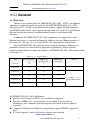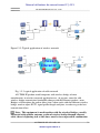
1
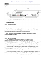
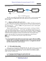
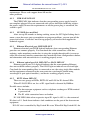
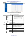
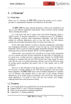
Manuel utilisateur du convertisseur IP / 4 E1 AN-TDM-IP-4E1-8E1-16E1-AP E1/T1 over Ethernet Multiplexer User’s Manual AD-NET TECHNOLOGY CO., LTD contents -1- www.hypercable.fr Manuel utilisateur du convertisseur IP / 4 E1 AN-TDM-IP-4E1-8E1-16E1-AP E1/T1 over Ethernet Multiplexer User’s Manual AD-NET TECHNOLOGY CO., LTD 2012.05 contents -2- www.hypercable.fr Manuel utilisateur du convertisseur IP / 4 E1 Disclaimer The information contained in this document is subject to change without notice and does not represent a commitment on the part of AD-NET TECHNOLOGY CO., LTD (AD-NET). The information in this document is believed to be accurate and reliable; however, AD-NET assumes no responsibility or liability for any errors or inaccuracies that may appear in the document. Copyright 2012 by AD-NET TECHNOLOGY CO., LTD All rights reserved. No part of this publication may be reproduced or distributed in any form or by any means, without prior written permission of AD-NET. Product Model: Product Name: Manual Version: Last Update: AN-TDM-IP-4E1-8E1-16E1-AP E1/T1 over Ethernet Multiplexer 1.0 May . 2012 contents -3- www.hypercable.fr Manuel utilisateur du convertisseur IP / 4 E1 TABLE OF CONTENTS GENERAL ........................................................................................... 1 1. 1.1 OVERVIEW ............................................................................................... 1 AN-TDM-IP-4E1-8E1-16E1-AP FEATURES ........................................................ 1 1.2 APPLICATIONS.......................................................................................... 2 1.3 TIMING MODES ......................................................................................... 4 SYSTEM ARCHITECTURE .......................................................... 5 2. 2.1 FUNCTION DESCRIPTION .......................................................................... 5 2.2 STRUCTURE .............................................................................................. 6 2.3 FRONT PANEL ........................................................................................... 6 2.3.1 Diagram .......................................................................................... 6 2.3.2 LED’s .............................................................................................. 8 2.3.3 Dip Switches Definition ................................................................ 10 2.3.4 E1/T1 Port..................................................................................... 11 2.3.5 Ethernet port ................................................................................. 13 2.3.6 Power Switch and Power Socket................................................... 14 INSTALLATION............................................................................ 14 3. 3.1 MECHANICAL ......................................................................................... 14 3.2 ELECTRICAL ........................................................................................... 15 3.2.1 Power connection.......................................................................... 15 3.2.2 E1/T1 connections......................................................................... 15 3.2.3 Ethernet cable/optic fiber connections ......................................... 16 TROUBLESHOOTING ................................................................. 16 4. 4.1 COMMON FAULT DIAGNOSIS AND RULED OUT......................................... 16 4.1.1 PWR FAIL LED ON ...................................................................... 17 4.1.2 SYS LED does not blink ................................................................ 17 4.1.3 Ethernet Electrical port LINK LED OFF ..................................... 17 4.1.4 Ethernet optical port L/A LED OFF or OLOS LED ON .............. 17 4.1.5 E1/T1 Alarm LED ON................................................................... 17 4.1.6 TWO ENDS DEVICES CANNOT CONNECT .............................. 18 4.1.7 Both Sides devices of E1/T1 have slip........................................... 18 WEB MANAGER ........................................................................... 18 5. 5.1 SYSTEM INFO ......................................................................................... 19 5.2 ALARM STATUS...................................................................................... 20 5.2.1 E1 Channel Status ......................................................................... 20 contents -4- www.hypercable.fr Manuel utilisateur du convertisseur IP / 4 E1 5.2.2 Ethernet Port Status ...................................................................... 20 5.2.3 Power Status ................................................................................. 21 5.2.4 Alarm Log ..................................................................................... 21 5.3 ALARM MANAGEMENT .......................................................................... 21 5.3.1 Alarm Shielding Management....................................................... 21 5.4 ETHERNET MANAGEMENT...................................................................... 22 5.4.1 Ethernet Management ................................................................... 23 5.4.2 Ethernet Senior Management........................................................ 23 5.4.3 VLAN Management ....................................................................... 25 5.5 E1 MANAGEMENT .................................................................................. 28 5.5.1 E1 Service Management................................................................ 28 5.5.2 E1 Senior Management ................................................................. 28 5.5.3 Error test ....................................................................................... 31 5.6 SNMP MANAGEMENT ........................................................................... 31 5.7 SYSTEM CONFIGURATION....................................................................... 32 5.7.1 System time management .............................................................. 32 5.7.2 password management .................................................................. 33 5.7.3 Default parameter recovery .......................................................... 33 5.7.4 Upgrade online ............................................................................. 35 5.7.5 Reboot system................................................................................ 37 6. SPECIFICATION........................................................................... 37 6.1 6.2 6.3 6.4 6.5 6.6 6.7 6.8 CAPACITY .............................................................................................. 37 E1/T1 INTERFACE FEATURES ................................................................. 37 ETHERNET PORT..................................................................................... 38 POE FUNCTION ...................................................................................... 38 POWER ................................................................................................... 38 OPERATING CONDITION .......................................................................... 38 DIMENSIONS........................................................................................... 39 WEIGHT ................................................................................................. 39 APPENDIX............................................................................................... 39 contents - www.hypercable.fr Manuel utilisateur du convertisseur IP / 4 E1 www.hypercable.fr Manuel utilisateur du convertisseur IP / 4 E1 AD-NET TECHNOLOGY CO., LTD 1. General 1.1 Overview Thank you for selecting the AN-TDM-IP-4E1-8E1-16E1 E1/T1 over Ethernet multiplexer product designed and made by AD-NET TECHNOLOGY CO., LTD This converter T1 / E1 data encapsulated in the packet , support SAToP agreement and UDP/IP packet mode,that supports transportation of 4~16 E1 /T1 over FE port, that can be used to provide E1 communication channels over Ethernet or IP networks. In addition, AN-TDM-IP-4E1-8E1-16E1 equipment also support the 2 local Ethernet data access, its internal buildup QoS which set the local Ethernet priority is lower than T1 / E1 data, so as to ensure the T1 / E1 signal priority transmission. The AN-TDM-IP-4E1-8E1-16E1 has many optional parameters, which can be modified by the user to suite different application requirements. Please read this manual carefully before installing the product. AN-TDM-IP-4E1-8E1-16E1 model number is the table1.1-1 Table 1.1-1 model numbers Type E1/T1connector qty 100Base-Tx electrical port 100Base-Fx optical qty AN-TDM-IP-16E1-A 16 4 1 AN-TDM-IP-8E1-A 8 4 1 AN-TDM-IP-4E1-A 4 4 1 16 4 1 AN-TDM-IP-16E1-AP remark 2 AN-TDM-IP-8E1-AP 8 4 1 AN-TDM-IP-4E1-AP 4 4 1 uplink port support(POE) functio n AN-TDM-IP-4E1-8E1-16E1-AP Features provide 4/8/16 channel of E1/T1 over one Ethernet adaptive Provide 4 100Base-Tx electrical ports (2 for uplink, 2 for user data or monitoring) and 1 Ethernet optical port optical port can be used for uplink or user data. support SAToP protocol, Ethernet encapsulation support IP/UDP.,support E1 Qos E1 clock supports 3 mode: local clock, adaptive and loopback www.hypercable.fr AN-TDM-IP-4E1-8E1-16E1-AP -1- Manuel utilisateur du convertisseur IP / 4 E1 Hua huan Beijing AD-NET Electronics Co., Ltd 2 uplink Ethernet electrical port support 1 + 1 nondestructive protection; For AP type series equipment, 2 uplink port support Ethernet feeder (POE) function, can provide the equipment with 55 V DC, feeder power can arrive 50 W Ethernet built-in layer 2 switch, support VLAN(802.1Q based and QinQ based), port based、8021.1P based and TOS based) Support port speed limited, flow control, MAC address automatic learning and MAC address aging time set; Support RJ-48 C form of 120 Ω _E1/100 Ω _T1 interface, through the dip of bottom setting and special cable change into the 75 Ω unbalanced interface, so as to realize the impedance matching; High transmission efficiency, low transmission delay Frequency reduction stability, low jitter and drifting Resist to packet loss, no jump frequency, with frame synchronization protection, Enough jitter buffer to resist packet delay variation (PDV) User-friendly Web server supported for easy setup and maintenance Support SNMP network management (V2 version ) Support Local and remote Software and hardware online upgrade Support SNTP network time setting Support software test E1 error AN-TDM-IP-4E1-8E1-16E1-AP support AC 100 ~ 260 V and DC-48 V double power supply, AN-TDM-IP-4E1-8E1-16E1-A support AC + DC) or double DC power supply, realize 1 + 1 backup 1.2 Applications … AN-TDM-IP-4E1-8E1-16E1-AP could be worked with E1 over Ethernet interface multiplexer AN-TDM-IP-STM-1, make point-to-multipoint application ,and point to point of connection, Typical application is shown in Fig 1.2-1~Fig 1.2-3. Figure 1.2-1 AN-TDM-IP-4E1-8E1-16E1-AP Convergent Application -2- AN-TDM-IP-4E1-8E1-16E1-AP www.hypercable.fr Manuel utilisateur du convertisseur IP / 4 E1 AD-NET TECHNOLOGY CO., LTD BTS E1/T1 Uplink FE Wireless Transport Uplink FE E1/T1 MUX MUX- E1/T1 E1/T1 PCM PBX FE FE Computer Local Ethernet Figure1.2-2 Typical application of wireless network E1/T1 BTS E1/T1 Wireless Transport FE E1/T1 Mux Metro Ethernet/ IP FE E1/T1 Mux PCM PBX FE FE Computer Local Ethernet Fig. 1.2-3 typical application of cable network AN-TDM-IP product could cooperate with wireless bridge of most manufactories in wireless network application use, At present, some the sold wireless bridge transmission bandwidth change with the Ethernet packets, some Bridges will introduce the packet delay jitter, when work with the different wireless bridge, need to adjust E1/T1 signal packet length and jitter, in order to get the best transmission effect. Note : This equipment is used together with the wireless Bridges, usually connected with outdoor antenna system of wireless bridge through ethernet cable, there is lightning risk at this time, must be in an upward in combination AN-TDM-IP-4E1-8E1-16E1-AP www.hypercable.fr -3- Manuel utilisateur du convertisseur IP / 4 E1 AD-net AD-net Technology Co., LTD of Ethernet lightning protection protector, otherwise lightning will make seriously damage to the equipment, danger to the staff . 1.3 Timing modes To emulate a transparent E1 channel over a packet network, the AN-TDM-IP-4E1-8E1-16E1-AP not only conveys data stream content correctly from the source to the destination, but also recovers the E1/T1 timing from the source at the destination accurately. Packet networks do not provide such built-in timing transparency mechanism as TDM networks do. AN-TDM-IP16 uses its proprietary algorithm to reconstruct the E1 clock at the destination. The recovered clock is of very high quality, with low jitter and wander. Typical frequency offset is within ±5ppm, and jitter is below 0.1UI. It can be adopted in most applications. This timing mode of rebuilding the E1 clock at the destination is called Adaptive Timing. Therefore, this series equipment provides another mode , loop back timing mode. In this mode, AN-TDM-IP-4E1-8E1-16E1-AP series equipment with T1 / E1 input signal from the port of clock T1 / E1 reconstruction output data stream, by TDM-IP. SA16 series equipment of internal memory will absorb completely network transmission of the formation of the drift. Once the input signal loss fault, will automatically switch to adaptive timing. AN-TDM-IP-4E1-8E1-16E1-AP series equipment with two kinds of timing mode is as the figure 1.3-1 AN-TDM-IP IN IN E1/T1 interface E1/T1 interface OUT Timing Recovery OUT Adaptive Timing AN-TDM-IP Timing Extraction Buffer Cache Loop back Timing Fig.1.3-1 Timing modes Correct timing mode setting is important for smooth operations. In most cases, setting both units to adaptive timing mode is sufficient. But sometimes, setting one unit to loop timing mode may work better. For example, setting the AN-TDM-IP-4E1-8E1-16E1-AP unit connected with the clock master (such as local exchange) to loop back mode, and the other unit connected with the clock slave (such as PBX or remote module) to adaptive mode, is probably better than setting both to adaptive modes. One typical error in telecom applications is to connect two communication devices that are both clock slaves. Neither will AN-TDM-IP-4E1-8E1-16E1-AP support such operation no mater how the timing modes are set. -4- AN-TDM-IP-4E1-8E1-16E1-AP www.hypercable.fr Manuel utilisateur du convertisseur IP / 4 E1 AD-net AD-NET TECHNOLOGY CO., LTD Note: The Lock Clock usually takes several minutes to stabilize. During that period, clock drift may exceed the limit, errors and slips may occur. Various timing schemes are listed in Table 1.4-1, for applications depicted in Fig.1.3-2. A side Equipment A side Mux E1/T1 B side Mux Ethernet or IP E1/T1 FE FE B side Equipment Fig.1.3-2 Timing mode scheme reference diagram Table 1.3-1 Timing mode schemes A side Equipment clock mode B side Equipment clock mode master master master master master slave slave master slave slave 2. A side B side Mux Mux Timing mode Timing mode loop back loop back adaptive adaptive adaptive adaptive loop back adaptive adaptive adaptive adaptive adaptive loop back adaptive Note Equipment A & B clocks synchronous Equipment A & B clocks plesiochronous Not allowed System Architecture 2.1 Function Description The core of AN-TDM-IP-4E1-8E1-16E1-AP is the TDM/Packet processing unit. It truncates E1/T1 data stream, and encapsulates the data into Ethernet packet with or without IP headers. The packets are passed to the Ethernet switch unit via MII interface, and are sent out through the uplink ports. In the reverse direction, packets from the uplink ports are sent to the TDM/Packet processing unit for reassembling the original E1/T1 data stream, and outputting via E1/T1 interface. TDM/Packet processing unit need to process the reassembled data to recover the E1 clock which is the key element of the device. Very sophisticated algorithm is used to ensure that the reconstructed clock will meet the stringent requirement of TDM applications. The most important parameters are bit rate, jitter, wander, and signal delay. The user can set various operational parameters through Network Management. AN-TDM-IP-4E1-8E1-16E1-AP www.hypercable.fr -5- Manuel utilisateur du convertisseur IP / 4 E1 AD-net AD-NET TECHNOLOGY CO., LTD 2.2 Structure AN-TDM-IP-4E1-8E1-16E1-AP adopt standard 1U box, which is composed by system board and power module. AN-TDM-IP-4E1-8E1-16E1-AP system structure is shown in Fig 2.2-1-2.2-2 Interface board System board PWR modue PWR module Fig 2.2-1 AN-TDM-IP system structure PoE PWR module PoE board Interface board System board Fig 2.2-1 AN-TDM-IP system structure 2.3 Front panel 2.3.1 Diagram AN-TDM-IP-4E1-8E1-16E1-AP, all service interface ,power port ,indicators and dips are in the front of panel , no indicators or dips in the rear panel , AN-TDM-IP-4E1-8E1-16E1-AP front panel is shown in Fig 2.3-1~Fig 2.3-9. E1/T1 3 LOS LOS/AIS E1/T1 FAR-END PKT UP 4 LOS LOS/AIS E1/T1 Uplink2 FAR-END PKT UP E1/T1 SYS 100FX RLB MASK LLB TMP_IP L/A 1 LOS LOS/AIS 2 Data 1 Data2/NM OLOS PWR FAIL Fig. 2.3-1 Front panel of 4E1 unit (DC-48V/100~240V AC) -6- AN-TDM-IP-4E1-8E1-16E1-AP www.hypercable.fr + LOS LOS/AIS FAR-END PKT UP 1 2 DC 48V FAR-END PKT UP o Uplink1 1 Manuel utilisateur du convertisseur IP / 4 E1 AD-NET AD-NET TECHNOLOGY CO., LTD Uplink1 1 2 FAR-E ND UP PKT LOS LOS/AIS E1/T1 3 FAR-END UP PKT LOS LOS/AIS E1/T1 4 FAR-END UP PKT LOS LOS/AIS E1/T1 Uplink2 FAR-END UP PKT LOS LOS/AIS SYS 10 FX RLB MASK LLB TMP_IP DC 48V DC 48V + + - - 1 L/A o 1 2 E1/T1 Data 1 OLOS PWR Data2/NM FAIL Fig. 2.3-2 Front panel of 4E1 version (Dual DC-48V ) Uplink1 Uplink2 2 FAR-E ND FAR-END 4 FAR-END 10FX E1/T1 E1/T1 L/A 2 PW R FAIL 2 OLOSPoE Data2/NM TMP_IP 1 1 Data 1 MASK SYS LLB UP PKT LOS LOS/AIS + E1/T1 RLB FAR-END UP PKT LOS LOS/AIS DC 48V UP PKT LOS LOS/AIS UP PKT LOS LOS/AIS E1/T1 3 1 o 1 Fig. 2.3-3 Front panel of 4E1 version with POE (-48V DC/100~240V AC ) 5 6 7 Uplink 1 8 Uplink2 SYS 100FX FAR-END 3 4 4 56 7 8 TMP_IP 1 2 Da ta 1 ERR Data2/NM + 2 3 MASK LLB DC 48V 1 12 RLB L/A UP PKT LOS/AIS/ 1 o PORT E1/T1 OLOS PWR FAIL Fig. 2.3-4 Front panel of 8E1 version (-48V DC/100~240V AC ) 5 6 7 Up lin k1 8 PORT E1/T 1 1 2 3 12 4 7 ERR 8 SYS 10 FX FAR-END UP PKT LOS/AIS/ 45 6 3 Uplink2 RLB MASK LLB TMP_IP DC 48V DC 48V + + - - 1 L/A o 1 2 Data1 O LO S PW R Data2/NM FAIL Fig. 2.3-5 Front panel of 8E1 version (Dual -48V DC ) 5 6 7 Uplink1 8 Uplink2 3 12 4 3 4 56 7 8 Data1 Data2/NM 1 1 2 2 PW R FAIL OLOSPoE RLB MASK LLB TMP_IP + 2 L/A UP PKT LOS/AIS/ ERR DC 48V 1 SYS 100FX FAR-END 1 o PORT E1/T1 Fig. 2.3-6 Front panel of 8E1 version with POE (-48V DC/100~240V AC) 9 10 11 12 13 14 15 16 PKT LOS 59131 Uplink1 LOS/AIS/E RR 5 9 13 Uplink2 SYS L/A RLB MASK LLB TMP_IP 1 2 2 3 4 5 6 7 8 4 8 12 16 4 8 12 16 4 8 12 16 + 1 Data1 - DC 48V PORT 100FX E1/T1 OLOS PWR FAIL Data2/NM 1 FAR-END UP 5 9 13 1 o 1 Fig. 2.3-7 Front panel of 16E1 version (-48V DC/100~240V AC) 9 10 11 12 13 14 15 16 1 FAR-END UP 5 9 13 1 PKT LOS 59131 Uplink1 LOS/A IS/E RR 5 9 13 Uplink2 PORT SYS 100FX RLB MASK LLB TMP_IP L/A E1/T1 1 2 1 2 3 4 5 6 7 8 4 8 12 16 4 8 12 16 4 8 12 16 Data1 Data2/NM 1 DC 48V DC 48V + + - - o OLOS PWR FAIL Fig. 2.3-8 Front panel of 16E1 version (Dual -48V DC) AN-TDM-IP-4E1-8E1-16E1-AP www.hypercable.fr -7- Manuel utilisateur du convertisseur IP / 4 E1 AD-net AD-net Technology CO., LTD 9 10 11 12 13 14 15 16 PKT LOS 5 9 13 1 Uplink1 LOS/AIS/E RR 5 9 13 Uplink2 A RLB L/A E1/T1 2 3 4 5 6 7 8 4 8 12 16 4 8 12 16 4 8 12 16 Data2/NM 1 2 OLOSPoE MASK TMP_IP 1 2 PW R FAIL + 1 Data 1 SYS LLB DC 48V PORT 100FX 1 FAR-END UP 5 9 13 1 o 1 Fig. 2.3-9 16E1 version with POE (-48V DC/100~240V AC)) LED’s 2.3.2 The definition is shown in Table 2.3-1: Table 2.3-1 the indicators definition of AN-TDM-IP-4E1-8E1-16E1-AP Definition Identification Color Quantity SYS PWR FAIL L/A OLOS -8- Green 2 Green Red System working state instructions Blink: Normal On: System is on configuration or work abnormally Off: System does not work or abnormally work 1 Red Remark 1 1 The power failure alarm instructions On: Power Off / Failure Off: Normal • 0ptical Ethernet interface state instructions On: Connected with remote Ethernet optical interface Off: Not connected with Ethernet optical interface Optical Ethernet interface receiving AN-TDM-IP-4E1-8E1-16E1-AP www.hypercable.fr Indicators 1,2 is corresponding to the left and right power supply Optical Ethernet interface indicators Manuel utilisateur du convertisseur IP / 4 E1 AD-net AD-NET TECHNOLOGY CO., LTD (Ethernet electrical port LINK) Green 4 Yellow 4 (Ethernet electrical port FDX) instructions On: No receiving Off: Receiving normally Ethernet electrical interface instructions On: Link normally Blink: Data transmitting/receivin g Off: Link abnormally Ethernet electrical interface rate instructions: On :rate is HULL Off :rate is HALF Uplinked POE POE Yellow 2 FAR-END UP 1~16 PKT LOS Green 16 Red 16 Red 16 1~16 LOS/AIS 1~16 instructions: On :power supply Off :no power supply One link indicator on the left of each Ethernet electrical interface One FDX indicator on the right of Ethernet electrical interface Only H0FLEthMux. SAP1604/SAP1608 / SAP16,indicators 1,2 is separately corresponding to the unlinked port 1, 2 E1 / T1 addressing the remote equipment link state instructions On: Addressing the remote MAC address Off: unaddressing the remote MAC address E1 / T1 service lost package instructions in Ethernet link On: Cannot receive the E1/T1 remote package Blink: Remote E1/T1 lost package or disorderly sequence Off: Remote E1/T1 no lost package and disorderly sequence E1 / T1 port alarm status instructions AN-TDM-IP-4E1-8E1-16E1-AP www.hypercable.fr -9- Manuel utilisateur du convertisseur IP / 4 E1 AD-NET TECHNOLOGY CO., LTD AD-net On: LOS alarm Regular slow blink: AIS alarm Irregular fast blink: receive HDB3 code ,wrong E1/T1 signal Off: no alarm 2.3.3 Dip Switches Definition There are four Dip Switches on the front panel, the definition show in Table 2.3-2. Table 2.3-2 AN-TDM-IP-4E1-8E1-16E1-AP Dip Switches Definition of front panel Dip label DIP-1 LLB DIP-2 RLB DIP-3 MASK DIP-4 TMP_IP Definition E1/T1 port Tx to Rx loop back ON: set local E1/T1 port Tx to Rx loop back OFF: cancel local E1/T1 port Tx to Rx loop back E1/T1 port Rx to Tx loop back ON: set local E1/T1 port Rx to Tx loop back OFF: cancel local E1/T1 port Rx to Tx loop back Alarm mask set ON: set local alarm mask Off; cancel local alarm mask IP set ON: restore default IP address 192.192.192.192 OFF: use the user’s Setting IP address Note :1) Dial TMP_IP dip ,5 minutes later, no matter whether the user dial up ,will return to the original user Settings IP 2) Dial down all the dips , power failure will recover the default setting of the factory, but keep the current IP address, MAC address There is one group of 8 DIP 1, on the bottom of H0FL-EthMux. SA1604 / SAP1604 , two groups of 8 dips, DIP1~DIP2 on the bottom of H0FL-EthMux. SA1608 / SAP1608 ,4 grops of 8 dips, DIP1~DIP4 on the bottom of AN-TDM-IP-4E1-8E1-16E1-AP,used to control the T1 / E1 interface impedance and 75 Ω unbalancedinterface shell grounding , every 8 dips control 4 channel T1 / E1 interface, which DIP1definiation is as the table 2.3-3 shows, DIP2-DIP4 defination is on the analogy of .this Table 2.3-3 AN-TDM-IP-4E1-8E1-16E1-AP Dip Switches Definition of bottom panel - 10 - AN-TDM-IP-4E1-8E1-16E1-AP www.hypercable.fr Manuel utilisateur du convertisseur IP / 4 E1 AD-net AD-NET TECHNOLOGY CO., LTD Dip One Two Three Four Five Six Seven eight Definition ON: the first channel of E1/T1 Interface impedance is 75 Ω OFF: the first channel of E1/T1 Interface impedance is 120Ω-E1/100Ω-T1 ON: the first channel of E1/T1 Interface shell grounding OFF: the first channel of E1/T1 Interface shell suspended ON: the second channel of E1/T1 Interface impedance is 75 Ω OFF: the second channel of E1/T1 Interface impedance is 120Ω-E1/100Ω-T1 ON: the second channel of E1/T1 interface shell grounding OFF: the second channel of E1/T1 interface shell suspended On : the third channel of E1/T1 Interface impedance is 75 Ω Off:the third channel of E1/T1 Interface impedance is 120Ω-E1/100Ω-T1 ON: the third channel of E1/T1 interface shell grounding OFF: the third channel of E1/T1 interface shell suspended On : the fourth channel of E1/T1 Interface impedance is 75 Ω Off:the fourth channel of E1/T1 Interface impedance is 120Ω-E1/100Ω-T1 ON: the fourth channel of E1/T1 interface shell grounding OFF: the fourth channel of E1/T1 interface shell suspended E1/T1 Port 2.3.4 AN-TDM-IP equipment with 4 channel of 120 Ω-E1/100 Ω-T1 balance interface, AN-TDM-IP equipment with 8 channel of 120 Ω-E1/100 Ω-T1 balance interface, AN-TDM-IP equipment with 16 channel of 120 Ω-E1/100 Ω-T1 balance interface, all adopt RJ-48 C form. RJ-48 C joints and wire sequence and signals defined as follows. . AN-TDM-IP-4E1-8E1-16E1-AP www.hypercable.fr -11- Manuel utilisateur du convertisseur IP / 4 E1 AD-net AD-NET TECHNOLOGY CO., LTD 1 8 Fig 2.3-5 RJ48-C socket pin sequence Table 2.3-4 AN-TDM-IP RJ-48C socket signal definition Pin 1 - Signal 2 + 3 GND E1-IN 4 5 + E1-OUT 6 7 8 GND Table 2.3-5 AN-TDM-IP-4E1-8E1-16E1-AP RJ-48C socket signal definition PIN E1connecting 1 2 3 4 5 6 7 8 E1_IN(1)E1_IN(1)+ E1_OUT(1)+ E1_OUT(1)E1_IN(2)E1_IN(2)+ E1_OUT(2)+ E1_OUT(2)- Twisted pair pair pair pair pair Using 5 cable making pairs color of the recommended Blue Blue white Orange Orange white Green Green white Brown Brown and white On the bottom of this series equipment have 1 ~ 4 group of 8 DIP, used to control the impedance of the T1 / E1 interface and 75 Ω unbalance interface shell grounded. When the interface choose 75 Ω impedance, 4E1, 8E1 equipment can use BH4.815.122 cable which convert 120 Ω-cable E1/100 Ω-T1 balance interface (RJ-48 C) to 75 Ω unbalanced interface (BNC). The "+" connect core, ―-‖connect skin. H0FL-EthMux. 16E1 equipment use the BH4.815.123 cable which convert 120 Ω-cable E1/100 Ω-T1 balance interface (RJ-48 C) to 75 Ω unbalanced interface (BNC). The "+" connect core―-‖connect skin 16E1 series series equipment T1 / E1 interface through network provide RxTx, Tx Rx loop back operation, convenient opening, maintain test. Loop back definition details are in 3.1.2 description. Section Node : 1. T1 / E1 interface card don’t support a hot swap.if need to change , please shut off the power - 12 - AN-TDM-IP-4E1-8E1-16E1-AP www.hypercable.fr Manuel utilisateur du convertisseur IP / 4 E1 Hua huan AD-NET TECHNOLOGY CO., LTD 2. T1 / E1 interface using RJ48-C socket, 16E1 equipment one socket corresponding two channel T1 / E1, belonging to private definition, don't make the interface with the 4E1, 8E1 equipment standard RJ-48 C socket confusion, or it will damage the interface. 3. T1/E1 interface choice set by the network management software. 2.3.5 Ethernet port There are four 100Base-Tx Ethernet electrical ports (two ports are uplink ports used to connect with transmission network and the other two are local data ports used to connect with local Ethernet), and one 100Base-Fx optical port used as either uplink port or local data port. Ethernet electrical port supports three modes: auto-negotiation, 10M full duplex/half-duplex and 100M full-duplex/half-duplex. Ethernet optical port supports auto-negotiation or 100M full-duplex mode. Ethernet built-in layer-2 switches function. Supporting Ethernet packet size up to 2000 bytes, Support port speed limited, IEEE802.3 x flow control, the MAC address automatic learning and MAC address aging time function set e tc.VLAN setting based on 802.1Q or QinQ, QoS setting based on port、8021. 1P and TOS. Ethernet electrical port adopts RJ45 socket. RJ45 Ethernet socket is defined in Table 2.3-5. Ethernet optical port can use double-fiber SFP optical module and the port labeled( is for optical signal output, ( for input. Also Ethernet optical port can use single-fiber optical module which has only one optical interface The wavelength of the single fiber module is the optical wavelength, or for 1310 nm, or for 1550 nm. Depending on different transmission distance, Different SFP optical module could be selected. Table 2.3-5 RJ45 socket definition Pin 1 2 Definition TxD+ TxD- 3 4 5 RxD+ 6 7 8 RxD- AN-TDM-IP-16E1-AP series equipment two unlinked electronical Ethernet p ort control (POE) function by Webserver network management, open after P OE by Ethernet data pin provide 55 V DC (support output short circuit pr otection function) to net Bridges , feeding power can be up to 50 W, at t he same time ,not influence the data transmission. Its RJ45 Ethernet socket AN-TDM-IP-4E1-8E1-16E1-AP www.hypercable.fr -13- Manuel utilisateur du convertisseur IP / 4 E1 Hua huan Beijing AD-NET Electronics Co., Ltd application feet when idle power supply, pin 4, and 5 connection is for the positive, pin 7, 8 connection for is negative, such as table 2.3-6 descriptio n. Pin Defini on Table 2.3-6 support POE function RJ45 Ethernet socket definition 1 2 3 4 5 6 7 8 TxD+ TxD- RxD+ 55V+ 55V+ RxD- 55V- 55V- Note: 1. AN-TDM-IP-16E1-AP series equipment can make Ethernet supply power function that the uplinked port in the transmission of data and will provide 55 V dc continuously, need to pay attention to safety, Ethernet cable don't be naked. 2. AN-TDM-IP-16E1-AP series equipment can make Ethernet supply power function that the uplinked port must not connect with monitoring computer, in order to avoid damage. Therefore recommended Data2 / NM monitoring port 3. AN-TDM-IP-16E1-AP series equipment can make Ethernet supply power function that cannot set Ethernet loop back (including software loop back and adopted Ethernet cable of hardware loop back) IN auto-negotiation mode, AN-TDM-IP-16E1-AP Ethernet electrical port supports HP auto-MDIX function and it can check the transmission and receiving sequence and make configuration. So both MDI and MDI-X interfaces are supported and both cross line and direct line can be selected. 2.3.6 Power Switch and Power Socket Two power options are available, ~220V AC or -48V DC. It should be specified at the time of purchase. 3. Installation 3.1 Mechanical AN-TDM-IP-16E1-AP can be placed at the table top or mounted on a 19‖ rack,The mechanical dimensions of AN-TDM-IP-16E1-AP are given in - 14 - AN-TDM-IP-4E1-8E1-16E1-AP www.hypercable.fr Manuel utilisateur du convertisseur IP / 4 E1 AD-NET AD-NET TECHNOLOGY CO., LTD Fig.3.1-1. 440 mm 136.5 mm 44 mm 31. 8 mm 9 10 11 12 13 14 15 Uplink1 16 PK TLOS 5 Uplink2 H0FL-EthMux SA16 LOS/AIS/ERR 9 13 1 5 9 13 2 3 4 5 6 7 8 4 8 12164 8 12164 8 12 16 Data1 Data2/N M SY S RLB MASK LLB TMP _IP 1 2 OLOS PWR FAIL + 1 L/A DC 48 V POR T 100FX E1/T1 1 913 o FA R-E N D U P 1 5 482 mm Fig.3.1-1 AN-TDM-IP-16E1-AP 3.2 3.2.1 Mechanical dimensions Electrical Power connection For the -48V type, connect -48 supply to the power connector -48V port, and ground to the other port. For ~220V equipment, connect the device to the ~220V outlet with standard power cord supplied with the equipment. WARNING: The system must be securely connected to a good protective ground for safety. 3.2.2 E1/T1 connections AN-TDM-IP-4E1-A/P supports 4 channels E1-120Ω/T1-100Ω balanced interface and AN-TDM-IP-8E1-A/P can support 8 channels E1-120Ω/T1-100Ω balanced interfaces.AN-TDM-IP-4E1-8E1-16E1-AP can support 16 channels E1-120Ω/T1-100Ω balanced interfaces.The RJ-48C sockets are default for all the ports. Besides, it can also support 75Ω non-balanced interface by the Dip switches on the rear panel and external impedance converting cable. Note: AN-TDM-IP-4E1-8E1-16E1-AP one socket corresponding two E1/T1, belong to the proprietary protocol, should not make mix up with the RJ-48C socket of AN-TDM-IP POE version, It may damage the interface. E1/T1 interface provide RxTx、Tx Rx through NMS, and the loopback of E1 channels can be set up independently. RxTx、Tx Rx loop back definition is AN-TDM-IP-4E1-8E1-16E1-AP www.hypercable.fr -15- Manuel utilisateur du convertisseur IP / 4 E1 AD-net AD-net Technology CO., LTD shown in Fig 3.1.-1: E1/T1 tester AN-TDM-IP Ethernet or IP AN-TDM-IP Rx Tx Tx Rx Fig 3.1-1 E1/T1 loop back RxTx can test E1/T1 connection cable, and Tx Rx is used to test the whole circuit including AN-TDM-IP-4E1-8E1-16E1-AP in the two ends and the link between them. 3.2.3 Ethernet cable/optic fiber connections AN-TDM-IP-4E1-8E1-16E1-AP provides four 100Base-Tx Ethernet electrical interfaces (two ports are uplink port and the other two are local data ports,Data2 is as the monitoring port ), and one 100Base-Fx optical interface used as either uplink port or local Ethernet port Ethernet Optical adopts SFP integrated optical modules, and the port labeled ( is for optical signal output, ( for input. Also Ethernet optical port can use single-fiber optical module which has only one optical interface. The wavelength of single-fiber optical module means its luminescence wavelength, 1310nm or 1550nm. It should note that equipments with the same luminescence wavelength cannot connect with each other. So it should select the equipments with the match luminescence wavelength when using the single-fiber module. Note: 1. At auto-negotiation mode, Ethernet electrical port supports HP auto-MDIX function and it can check the transmission and receiving sequence and make configuration. So both MDI and MDI-X interfaces are supported and both cross line and direct line can be selected. Troubleshooting 4. After power up of equipment AN-TDM-IP-4E1-8E1-16E1-AP the system should start after 90seconds to work properly. The system completion startup SYS light change from long bright to flashing light. You can observe each interface light to judge each port working statue. 4.1 Common fault diagnosis and ruled out This paragraph describes common faults that may occur during installation and - 16 - AN-TDM-IP-4E1-8E1-16E1-AP www.hypercable.fr Manuel utilisateur du convertisseur IP / 4 E1 AD-net AD-NET TECHNOLOGY CO., LTD maintenance. Please seek support from AD-net for other problems. 4.1.1 PWR FAIL LED ON The PWR FAIL light indicates that the corresponding power supply board is not complete plugged in or not connected with, please check the following subject: the power supply to meet the requirements or not,the power plug is connected, the switch is open. 4.1.2 SYS LED does not blink After star up 90 seconds or during working statue, the SYS light flashing that is mean system have not start up completion or program problem, you can turn off the power and reboot, if still does not start up properly you need to find supplier for technical support. 4.1.3 Ethernet Electrical port LINK LED OFF Ethernet electrical port LINK light off indicates that corresponding Ethernet port does not connect properly. You can check the cable connection, cable line ordering, under mandatory mode does it using the straight-through cable (crossover cable),the electrical interface connection does match the client configuration whether, and connection with network device is working properly or not. 4.1.4 Ethernet optical port L/A LED OFF or OLOS LED ON Ethernet optical ports L/A light off indicate that the corresponding Ethernet does not establish connect properly. The OLOS light on indicates no received light. Can check the corresponding fiber is connected or not, the using single-fiber module and the equipment connected to the same emission wavelength (should using wavelength as pair optical modules), and device working properly or not. 4.1.5 E1/T1 Alarm LED ON There are two groups of LEDs, PKT LOS and LOS for E1 alarms LEDs. When E1 LOS LED is on, loss of E1 signal fault is detected by EthMux. Possible causes include: The downstream equipment such as telephone exchange or PCM terminal is powered off. The E1 cable connection looses or broken. E1 LOS LED blinks when respective input E1 signal is AIS, i.e. the content of E1 data is all 1. Such alarm indicates fault conditions on the part of the downstream equipment. E1 LOS site is controlled by Dip Switch RA state. When RA Dip Switch ON, the AN-TDM-IP-4E1-8E1-16E1-AP www.hypercable.fr -17- Manuel utilisateur du convertisseur IP / 4 E1 AD-net Technology CO., LTD AD-net red LEDs indicate remote E1 LOS state. When RA Dip Switch OFF, the red LEDs indicate local E1 LOS state. 4.1.6 TWO ENDS DEVICES CANNOT CONNECT Both sides of devices in the same Ethernet broadcast domain, checking both side of device IP address should on dual relationship. Check MAC address is unique (include other device on the same network); Using Ping command to check network, checking bandwidth is sufficient or not. If two sides of devices are not in same Ethernet segment, checking device IP default gateway setting, IP address, IP address mask, and check conflicts of MAC address or IP address; check bandwidth is sufficient. IP address and gateway address can be set by NMS, MAC address set by manufacture. Check both ends of the device VLAN setting should be in accordance with eachother. 4.1.7 Both Sides devices of E1/T1 have slip Check both sides devices AN-TDM-IP-4E1-8E1-16E1-AP E1/T1 clock setting, at least one of device should be Master-Clock. Check AN-TDM-IP-4E1-8E1-16E1-AP time mode setting. If both sides of the E1/T1 equipment are not in the state of the synchronization, H0FL-EthMuxSA16/SAP16 timing model must be adaptive timing, not loop timing. At beginning of startup, slip is normal. 5. Web Manager AN-TDM-IP-4E1-8E1-16E1-AP support Web Server to monitoring devices. Login Web Server need Username and Password, the default Username and password are ―admin‖, as below picture showed, at System setting you can change it. - 18 - AN-TDM-IP-4E1-8E1-16E1-AP www.hypercable.fr Manuel utilisateur du convertisseur IP / 4 E1 AD-net AD-NET TECHNOLOGY CO., LTD All Web Server include 7 parts: System Info, Alarm Status, Alarm Management, ETH Management, E1 Management, SNMP Management, and System. Following will introduce AN-TDM-IP-4E1-8E1-16E1-AP 5.1 the Web Server Management of System Info After login Web Server, will show Welcome page. In this page include Hardware version number, Software version number, Web manager version number, IP address, Subnet Mask, Gateway IP address, MAC address. IP address and Subnet address and Gateway address can be set by customer, other only for checking. As shown in Fig 5.1-1. The default setting IP address is 192.168.1.2. AN-TDM-IP-4E1-8E1-16E1-AP www.hypercable.fr -19- Manuel utilisateur du convertisseur IP / 4 E1 AD-NET TECHNOLOGY CO., LTD AD-net Fig 5.1-1 System Info 5.2 Alarm Status Alarm status include E1 channel, Ethernet port, power supply and alarm log. 5.2.1 E1 Channel Status Click left side of Alarm Status—Channel will show E1 Channel Service name, Loop status, E1 port LOS, AIS alarm and calculation of LOS, Remote Connection Status. E1 loop for testing connection, definition of LOOP please check 3.1.2. E1 Loop setting after submitting will changed, but not saved, after device startup E1 not in Loop stats. Please check Fig 5.2-1. 图 5.2-1 E1 Alarm Status 5.2.2 Ethernet Port Status Click Left side Alarm Status – ETH Port will show 4 Ethernet electrical ports and 1 optical port LINK UP/DOWN stats, as shown in Fig5.2-2. - 20 - AN-TDM-IP-4E1-8E1-16E1-AP www.hypercable.fr Manuel utilisateur du convertisseur IP / 4 E1 AD-net AD-NET TECHNOLOGY CO., LTD Fig 5.5-2 ETH port Alarm Status 5.2.3 Power Status Click left side Alarm Status – Power Status will show Power Alarm Status, include 2 power off alarm Status information, as shown in Fig 5.2-3. Fig 5.2-3 Power Status 5.2.4 Alarm Log Click Left side Alarm Status – Alarm Log, include Alarm Type, Alarm Item, Port number, time. As shown in Fig 5.2-4. Fig 5.2-4 Alarm Log 5.3 Alarm Management This section includes E1 channels, Ethernet port and power alarm shielding. 5.3.1 Alarm Shielding Management If set alarm mask, then this alarm will be shielded at alarm log, alarm indicator on panel and will not display no matter what situation is unless the mask is canceled. AN-TDM-IP-4E1-8E1-16E1-AP www.hypercable.fr -21- Manuel utilisateur du convertisseur IP / 4 E1 AD-NET TECHNOLOGY CO., LTD AD-net E1 channel supports not only shielding any alarm of any channel, but also batch shielding. But Ethernet port alarm and power alarm shielding can only be set one by one. As shown in Fig 5.3-1 , Fig 5.3-2 and Fig5.3-3 Fig.5.3-1 E1 alarm management Fig.5.3-2 Ethernet alarm management Fig.5.3-3 power alarm management 5.4 Ethernet Management This section includes Ethernet port management, Ethernet senior management (MAC address aging time, QoS management and port Throughput limiting) and VLAN management. - 22 - AN-TDM-IP-4E1-8E1-16E1-AP www.hypercable.fr Manuel utilisateur du convertisseur IP / 4 E1 AD-net 5.4.1 AD-NET TECHNOLOGY CO., LTD Ethernet Management Fig.5.4-1 Ethernet Management Table 5.4-1 Ethernet management parameters Parameters Options Port Service No. Link Ethernet Speed Management Duplex Explanation 5 Ethernet ports number Ethernet service No.: support at most 15 capital/small letters, digit and part special character input. Chinese character support 7 numbers( not support some special characters, as ― / ‖、― \ ‖ input). Link: indicate current Ethernet link(Up/Down) Speed: indicate current Ethernet speed(10/100Mbps) port Duplex: indicate current Ethernet work mode (HALF/FULL) 5 Ethernet ports work mode configuration: Auto-adaptive (default) Auto ,100 100M full 100M half M full, Mode 10M full 100M 10M half half, Electrical interface work modes have Auto, 100M 10M full, 10M half full, 100M half, 10M full and 10M half. Optical interface work modes have Auto and 100M full Note: The sentence with underline is default settings. 5.4.2 Ethernet Senior Management Ethernet senior management supports MAC address aging time, Ethernet port QoS management and throughput limiting. MAC address aging time range is 0~524287s (default: 300s).as the fig 5.4-2 AN-TDM-IP-4E1-8E1-16E1-AP www.hypercable.fr -23- Manuel utilisateur du convertisseur IP / 4 E1 AD-NET TECHNOLOGY CO., LTD AD-net Fig 5.4-2 Ethernet management For Ethernet interface 1~5, we can enable QoS (based on port,IEEE 802.1p and TOS) Fig 5.4-3 Ethernet QoS configuration Port throughput limiting of Ethernet senor management includes enable Ethernet port throughput limiting and speed configuration (supporting entry speed limiting)and storm Refrain . As shown in Fig 5.4-4. Speed class of Ethernet interface is shown in Table 5.4-2. When we configure the maximum port speed, if the value is not equal to any speed class, it will select the lower speed class proximal to this value. For example, value is set to 70, after clicking Submit, the value will change to 64, means the maximum speed is 64KB. Fig 5.4-4 Ethernet port speed limiting configuration and storm Refrain . Table 5.4-2 Speed class of Ethernet interface - 24 - AN-TDM-IP-4E1-8E1-16E1-AP www.hypercable.fr Manuel utilisateur du convertisseur IP / 4 E1 AD-net AD-NET TECHNOLOGY CO., LTD Speed limiting range Lower than 2M Higher than 2M,lower than 100M speed class interval 64KB minimum speed 64KB maximum speed 1.792MB 1MB 2MB 100MB VLAN Management 5.4.3 Two uplink Ethernet electrical interfaces support 1+1 Nondestructive protection. After enabling 1+1 protect, equipment configure Q in Q VLAN automatically and user only need to configure VID of uplink Ethernet electrical interface and monitoring port. As shown in Fig 5.4-5 and Fig 5.4.6. Fig 5.4-5 uplink 1+1 Nondestructive configuration Fig 5.4-6 configure Q in Q VLAN automatically Forbid uplink 1 + 1 nondestructive protection function.,AN-TDM-IP16 Ethernet supports 802.1 Q VLAN and Q in Q VLAN. 802.1Q VLAN is that adding the VLAN tag in front of Ethernet frame type. Q in Q VLAN is that nesting the VLAN (S-Tag) of operators in 802.1Q outer layer to enable the VLAN stacking. VLAN management parameters are shown in Table 5.4-3. AN-TDM-IP-4E1-8E1-16E1-AP www.hypercable.fr -25- Manuel utilisateur du convertisseur IP / 4 E1 AD-NET TECHNOLOGY CO., LTD Fig 5.4-7 VLAN management 1—VALN configuration Fig 5.4-8 VLAN management 2—E1 port configuration Fig 5.4-9 VLAN management 3—Ethernet port VLAN configuration Fig 5.4-10 VLAN management 4—VLAN Table - 26 - AN-TDM-IP-4E1-8E1-16E1-AP www.hypercable.fr AD-net Manuel utilisateur du convertisseur IP / 4 E1 AD-net AD-NET TECHNOLOGY CO., LTD Fig 5.4-11 VLAN management 5—VLAN configuration confirmation Table 5.4-3 VLAN management parameters Parameters VLAN Mode Options Disable 802.1Q Add the VLAN tag before Ethernet frame type. Q in Q Protection Control Service Protection Attribute Ethernet Port E1 Channel VLAN Configuration VLAN Configuration VLAN Table Add operators VLAN (S-Tag) in 802.1Q. Realizing VLAN stack. Disable: not supply slave transmission channel. Enable: Both master and slave transmission channels transport service and no data loss during protection switching. Attribute of 1~5 Ethernet port, including uplink port and data/monitoring port. Ethernet port number 1~5. VID VLAN ID, support 4094 VLAN, ID, range (1-4094) Port E1port number 1~2 VID VLAN ID, support 4094 VLAN, ID, range (1-4094) Define customer priority, including 8 PRI degrees (0-7). PRI is higher when this number is bigger. Priority Eth Name Ethernet Port Explanation No VLAN tag Ethernet port number 1~5. VLAN ID, support 4094 VLAN, ID, range (1-4094) Define customer priority, including 8 PRI Priority degrees (0-7). PRI is higher when this number is bigger. VLAN table configurations, inquiry, add and delete. VID AN-TDM-IP-4E1-8E1-16E1-AP www.hypercable.fr -27- Manuel utilisateur du convertisseur IP / 4 E1 AD-NET TECHNOLOGY CO., LTD Parameters Options Select VID Mbr. Untag AD-net Explanation When adding VLAN group or VLAN members, property configuration changed, it should be tick off. VLAN group ID, support 1-4094 VLAN group member, it will be VLAN member when tick off tagged/untagged, ticking off means (untag) Note: According to the PVID value of Data2/NM port, it will automatically generate a default monitoring VLAN entry and it cannot be changed. If it needs to modify the monitoring VID value, it needs to modify the PVID of monitoring port. 5.5 E1 Management E1 management includes E1 service management , E1 senior management, Bit error test. Every section has many parameters setting. As shown in Table 5.5-1: 5.5.1 E1 Service Management Fig 5.5-1 E1 channel Management 5.5.2 E1 Senior Management Fig 5.5-2 E1 channel senior Management - 28 - AN-TDM-IP-4E1-8E1-16E1-AP www.hypercable.fr Manuel utilisateur du convertisseur IP / 4 E1 AD-net AD-NET TECHNOLOGY CO., LTD Fig 5.5-3 TTL/TOS configuration of E1 channel Management Table 5.5-1 E1 Management parameters Parameters Selections Explanations E1 service name : support at most 15 capital/small letters, digit and part special character input. Chinese character support 7 numbers( not support some special characters, as ― / ‖、― \ ‖ input). Enable this E1 channel. Default: disable Adaptive Adaptive mode:E1 timing from remote E1 stream Service Name Enable Timing E1 Mode Loopback Local Channel Jitter 4~256ms Buffer Destinati on IP UDP Port Source Destination Loop back mode:E1 timing comes from local E1 stream Local mode: E1 timing comes from local equipment crystal oscillator Jitter absorption buffer: worked with the link with bigger jitter, used to buffer the receiving packets. Coming packets buffer to eliminate jitter. Range:4~256ms Default: 16ms Remote end IP address;4 E1 line IP addresses can be set separately Default 192.168.1.3 UDP Source Port: Effective range:1024~65535 UDP Destination Port: Effective range:1024~65535 AN-TDM-IP-4E1-8E1-16E1-AP www.hypercable.fr -29- Manuel utilisateur du convertisseur IP / 4 E1 AD-net AD-NET TECHNOLOGY CO., LTD Parameters Encapsul ation Selections IPv4_UDP Frame Advanced Size 1×128 byte 2×128 byte 4×128 byte Enable RTP Disable TTL/TOS Explanations IP Encapsulation Every Ethernet packet encapsulation length can select 1×128 byte /2×128byte/4×128 byte. The longer the packet is, the more E1 data encapsulated in the packet, the lower expense ratio is, the higher bandwidth efficiency is and the bigger time delay is. Vise versa. Default: 2 Real-time Transport Protocol, used to define E1 time Stamp. Default: Enable TTL: Time To Live, Default: 128 TOS: Type Of Service, Default: 184 Supplementary item: 1. Whether E1 bandwidth is adaptive depends on whether enable this E1. Suggestion: If this E1 is not used, it is better to let this E1 channel disabled. 2. Each end of Ethernet devices has a unique and fixed with 12 a hexadecimal MAC address, such as 80-80-80-80-80-80, can make the communication with other equipment. H0FL-EthMux. SA63 equipment Ethernet MAC address has formed , not need to set. H0FL-EthMux. SA16 series equipment support ARP protocol addressing, the opposite equipment or default gateway equipment's MAC address can automatically get through Negotiation, no need to set the opposite end MAC address, but need set up IP address Note:In Ethernet broadcast domain, all the equipment's MAC address m ust be the only, otherwise it will cause address conflict. 3. In order to improve the transmission service quality of E1 data ,according to provide transmission Ethernet whether support IEEE 802.1 Q, 802.1 AD and 802.1 p standard, H0FL-EthMux. SA16 / SAP16 series equipment can set the standard is packed to join contain priority VLAN label (V-Tag) or QinQ label (S-Tag). According to 802.1 Q/QinQ / 802.1 p standard packing, the encapsulation spending slightly bigger, but can be transmitted by higher priority. But not support 802.1 p standard network, there is no practical significance, but increases unnecessary transmission bandwidth costs , therefore, will make VLAN set to Disable - 30 - AN-TDM-IP-4E1-8E1-16E1-AP www.hypercable.fr Manuel utilisateur du convertisseur IP / 4 E1 AD-net 5.5.3 AD-NET TECHNOLOGY CO., LTD Error test Click BER Test will display error Test , including error Test enable, the selection of Test channels ,the selection of test start and end, port state r frame frame synchronization out-of-frame), (Bit), error-rate and Test duration , as shown in figure 5.5-4 . If need to test error for channel , the first elected "enable" and "start", and second click "submit" button for beginning to test. The end could choose the channel "stop", and click "submit" button, this time display test results. During test click on the "Refresh" button ,can inquiry test error. By the current time Fig 5.5-4 Error test 5.6 SNMP Management SMMP management is the figure 5.6-1,SNMP parameters is in the table 5.6-1 Fig 5.6-1 SNMP management Table 5.6-1 SNMP management parameters Parameters SNMP Configuration Information Option SNMP Read Community SNMP Write Community Explanations Read commands of device nodes (Read-only) Default: public Configure commands of device nodes Default: private AN-TDM-IP-4E1-8E1-16E1-AP www.hypercable.fr -31- Manuel utilisateur du convertisseur IP / 4 E1 AD-NET TECHNOLOGY CO., LTD Parameters SNMP Trap Community SNMP Port Number SNMP Trap SNMP Trap Address Address and Port SNMP Trap Port Option AD-net Explanations Receive commands of Trap Default: public The communication ports connecting the devices with SNMP, SNMP protocol, Default: port: 161 Address used to receive Trap information: The most addresses and ports can be set is up to 5. That means the device can sent Trap information to 5 network management equipments. SNMP Trap Address needs to be configured at the first time(initial value: 0), but it can be saved and recovered. Ports used to receive Trap information: it needs to be configured at the first time (initial value: 0), but it can be saved and recovered. 5.7 System Configuration This section includes time configuration, change the password, Default parameter recovery, upgrade online and reboot system. 5.7.1 System time management System time can be modified in three ways: manually enter the time, Get Local PC Time or SNTP network time. As shown in Fig 5.7-1. Fig 5.7-1 system time management - 32 - AN-TDM-IP-4E1-8E1-16E1-AP www.hypercable.fr Manuel utilisateur du convertisseur IP / 4 E1 AD-net AD-NET TECHNOLOGY CO., LTD SNTP management includes SNTP server option (stop/start/test), time setting interval (10~60000 minutes), SNTP server IP address and SNTP server status display (disable/enable, connect successfully/fail). Note: It needs to get the current time again once the power is off. 5.7.2 password management Fig 5.7-2 password management The change will be valid after confirm the submitting. 5.7.3 Default parameter recovery Default parameter recovery can make all the parameters recover to factory default except the IP address of equipments and the devices will reboot automatically. If not selected to remain current IP, IP address will also recover to factory default (192.168.1.2). At the same time, due to the change of IP, it will show Access failed. Then we need to restart Web Server. Fig 5.7-3 default parameters recovery AN-TDM-IP-4E1-8E1-16E1-AP supports changing E1/T1 port number. For example, change AN-TDM-IP16 E1/T1 port number to 1. It is shown as follows: Step 1. Generate the configuration code by verification code. Input the MAC AN-TDM-IP-4E1-8E1-16E1-AP www.hypercable.fr -33- Manuel utilisateur du convertisseur IP / 4 E1 AD-NET TECHNOLOGY CO., LTD AD-net address of AN-TDM-IP16 and set E1 number as 1 and then click Generate. Fig 5.7-4 generate configuration code Step 2. Input the configuration code and click Submit. Fig 5.7-5 change E1/T1 port number Step 3 .Check the E1/T1 number in Configuration Status to confirm whether the change is successful. - 34 - AN-TDM-IP-4E1-8E1-16E1-AP www.hypercable.fr Manuel utilisateur du convertisseur IP / 4 E1 AD-net AD-NET TECHNOLOGY CO., LTD Fig 5.7-6 change is successful 5.7.4 Upgrade online Both AN-TDM-IP-4E1-8E1-16E1-AP hardware and software program can be upgraded by ftp. Following will introduce Web Server upgrade online operation. Step 1: Use any FTP tool or input ftp://root:[email protected]/home/ftp directly in My Computer address bar to access the ftp server. And then copy the upgrade program to the server, as figure 5.7-7. Note: Hardware program file name is H_Patch.r, and software program file name is S_patch.r. The file name cannot be changed. Fig 5.7-7 upgrade online 1—upload upgrade program Step 2: Select program type (it is available to select software and hardware at the same time) and click Upgrade to start. AN-TDM-IP-4E1-8E1-16E1-AP www.hypercable.fr -35- Manuel utilisateur du convertisseur IP / 4 E1 AD-NET TECHNOLOGY CO., LTD AD-net Fig 5.7-8 upgrade online 2—upgrade program It may take several minutes to complete the upgrade. During the upgrade, we can refresh to check upgrade progress. Fig 5.7-9 upgrade online 3—during the upgrade When the upgrade is done, click Confirm to reboot the equipment. Login Web management again to check the version number and confirm the upgrade is successful. Fig 5.7-10 upgrade online 4—operate successfully Note: If the power is off during upgrade, it may make equipment not start and need to program procedures with download line. - 36 - AN-TDM-IP-4E1-8E1-16E1-AP www.hypercable.fr Manuel utilisateur du convertisseur IP / 4 E1 AD-net 5.7.5 AD-NET TECHNOLOGY CO., LTD Reboot system Fig5..7-11 Reboot equipment 6. 6.1 Specification Capacity AN-TDM-IP-4E1-A / P 4 E1/T1 ports, 4 100Base-Tx Ethernet electrical ports,1 100Base-Fx Ethernet optical port; AN-TDM-IP-8E1-A / P 8 E1/T1 ports , 4 100Base-Tx Ethernet electrical ports,1 100Base-Fx Ethernet optical port AN-TDM-IP-16E1-A / P 16 E1/T1 ports, 4 100Base-Tx Ethernet electrical ports,1 100Base-Fx Ethernet optical port 6.2 E1/T1 Interface Features Comply with ITU-T G.703 recommendation End-to-end delay (minimum delay setting): ≤ 10ms Output frequency offset (adaptive timing, stabilized): ≤5 ppm Output jitter (adaptive timing): ≤ 0.1UI Interface Impedance default:E1-120Ω/T1-100Ω; Supporting 75Ω Connector: RJ-48C Ports: AN-TDM-IP1604/SAP 1604 : 4 H0FL-EthMux SA1608/SAP1608 8 H0FL-EthMux SA16/SAP16 E1/T1 ports E1/T1 ports 16 E1/T1 ports AN-TDM-IP-4E1-8E1-16E1-AP www.hypercable.fr -37- Manuel utilisateur du convertisseur IP / 4 E1 AD-NET TECHNOLOGY CO., LTD AD-net 6.3 Ethernet Port Comply with IEEE 802.3、802.1Q、802.1ad、802.1P and relative other protocol. Operating Mode:electrical port support auto-negotiation forced 10M/100M, Half/Full Duplex ,optical support forced 100M full duplex MTU: 2000 byte Connector:100M Electrical port: RJ45 100M Optical Port: LC Interface no.: 100M Electrical Port:4 100M Optical Port: 1 6.4 POE function AN-TDM-IP-4E1-8E1-16E1-AP support POE function voltage:55V power:50W 6.5 Power AC: 100V~260V/50Hz ~60Hz (fuse: 1A) DC: -36V ~ -72V Power Consumption: AN-TDM-IP16: ≤7W AN-TDM-IP1604/SA1608: ≤6.5W 6.6 Operating condition Temperature: (0~45) ℃ Humidity: ≤90%RH (non-condensing) - 38 AN-TDM-IP-4E1-8E1-16E1-AP www.hypercable.fr uplinked could Manuel utilisateur du convertisseur IP / 4 E1 AD-net AD-NET TECHNOLOGY CO., LTD 6.7 Dimensions Width ×Height ×Depth (mm): 440×44×136.5 6.8 Weight Net wight ≤2.0kg Appendix Specialized terminologies and acronyms: Acronym TDM Explanations Time Division Multiplex SAToP Structure-Agnostic TDM over Packet DSCP Differentiated Services Code point UDP User Datagram Protocol QoS Quality of Service TOS terms of service TTL Time To Live VLAN Virtual Local Area Network RTP Real-time Transport Protocol SNTP Simple Network Time Protocol POE Power Over Ethernet AN-TDM-IP-4E1-8E1-16E1-AP www.hypercable.fr -39-