1
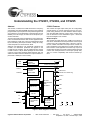
Understanding the CY2291, CY2292, and CY2295
Abstract
CY2291 Features
The CY2291, CY2292, and CY2295 are three-PLL frequency
synthesizers that utilize EPROM technology. Many different
programmable output frequencies and power saving features
are contained in one small package. These features result in
flexibility and cost savings, as well as short sample and production lead times.
The CY2291 has eight output clocks (four are configurable),
smooth slewing on outputs originating from the CPU PLL,
power-saving features, low skew between related outputs,
and user-selectable reference support. Each of these functions is discussed in more detail below. Figure 1 shows the
logic block diagram of the CY2291.
This document begins with an explanation of the CY2291 features. The internal architecture and common applications are
then presented. At that point, some recommendations about
layout and filtering techniques are made. Finally, the Configuration Request Form is discussed in detail.
Multiple Outputs
Although this application note specifically references the
CY2291, the information presented also applies to the
CY2292 and the CY2295. The only differences are that the
CY2295 comes in a 28 pin SSOP package and the CY2292
comes in a 16-pin SOIC package (32XIN, 32XOUT, 32K, and
VBATT are absent and the FLOPPYCLK output has been replaced with a GND pin on the CY2292).
32XIN
32XOUT
32 kHz
CRYSTAL
OSCILLATOR
The CY2291 has eight output pins, enabling it to support almost all PC motherboard clock requirements. These outputs
consist of four user configurable clocks, a CPUCLK, a FLOPPYCLK, a XBUF and 32-kHz clock output. Each of these outputs is explained in more detail in the CY2291 Internal Architecture section of this application note. When any output is in
a three-state condition, the signal is pulled LOW because the
CY2291 has weak pull-downs on all outputs (except 32K).
This is to ensure compatibility with Pentium™-based systems.
32K
CY2291 and CY2295 only
XBUF
XTALIN
XTALOUT
REFERENCE
CRYSTAL
OSCILLATOR
FLOPPYCLK
(CY2291 and CY2295 only)
CPUCLK
SYSCLK PLL
CLKA
OUTPUT
MULTIPLEXER
AND
DIVIDERS
CLKB
UTILITY PLL
CLKC
S2/SUSPEND
CPU PLL
CLKD
S1
S0
SHUTDOWN/OE
CPU EPROM
TABLE
CONFIGURATION
EPROM AND
TEST LOGIC
GND
VDD
VBATT
Figure 1. Block Diagram of CY2291/2/5
Cypress Semiconductor Corporation
•
3901 North First Street
•
San Jose
•
CA 95134 •
408-943-2600
September 19, 1995 – Revised July 2, 1997
Understanding the CY2291, CY2292, and CY2295
Variable Reference Frequency
Transitioning from the shutdown to active state requires the
PLLs to re-lock (50 ms maximum, 25 ms typical). In addition,
because the SHUTDOWN/OE pin has no pull-up resistors,
the user must drive this pin to a voltage level for proper operation.
The default reference frequency for the CY2291 is 14.318
MHz. However, the part can accept any reference frequency
between 10 MHz and 25 MHz, preferably from an accurate,
stable crystal which should be a parallel-resonant, fundamental mode crystal with CLOAD = 18 pF. In addition, this reference
crystal does not require any external resistors or capacitors.
The “Off” Option
The “off” option allows permanent shutdown of selected resources, independent of the suspend and shutdown options.
Selecting “off” for a PLL permanently shuts down the PLL and
all associated logic, and three-states associated outputs. Selecting “off” for an output simply three-states the output.
Alternatively, the CY2291 can use an external reference clock
of frequency between 1 MHz and 30 MHz. In this case, the
external reference clock is driven in over the XTALIN pin and
the XTALOUT pin is left floating. The duty cycle of this input
clock should be between 40% and 60% measured at V DD/2.
For more information on AC-coupling the external reference
clock, please refer to the application note “Crystal Oscillator
Topics.”
Unlike the suspend and shutdown modes:
• The “off” mode does not power-down the entire part.
• The “off” mode is pin-controllable only for the CPU PLL.
Smooth Slewing
Low Skew
The CY2291 provides smooth slewing on outputs originating
from the CPU PLL. The term “smooth slewing” refers to frequency slewing (the rate of change of frequency with respect
to time). Specifically, the frequency of such an output changes
smoothly and monotonically from 4 MHz to 80 MHz for 3.3V
operation and up to 100 MHz at 5V.
The CY2291 has low skew (500 ps maximum) between related signals on CLKA–CLKD, and CPUCLK outputs. Referring
to Table 1, related signals are defined as those which are on
the same row (except the “Ref” row). Therefore, SPLL/3 and
SPLL/6 are related, but SPLL/3 and SPLL/24 are not.
In addition, the outputs must have identical capacitive loads
to meet the skew specifications.
Smooth slewing is required for processors such as the 486,
which accept only a limited amount of frequency change per
clock cycle.
CY2291 Internal Architecture
In addition to a dedicated 32-kHz output, the CY2291 uses
three internal PLLs, EPROM technology, and a reference
crystal oscillator to synthesize up to four unrelated frequencies. These frequencies are then divided, using post-dividers,
allowing the device to provide up to a total of eight different
outputs.
Power-Saving Modes
The CY2291 features a variety of power-saving modes, which
are especially useful in Green PC and laptop applications.
Suspend Mode
The suspend option allows the user to activate and deactivate
selected resources at will. The suspend feature must be requested and the resources-to-be-suspended selected when
ordering the part.
The internal architecture of the CY2291 is explained in more
detail below.
Phase Locked Loop
Each of the three PLLs and each of the outputs, except for the
32.768-kHz output, can be suspended independently. Suspending a PLL shuts down all associated logic including
counters and downstream post- dividers, and places related
outputs in a three-state condition. Suspending an output simply forces a three-state condition on the output. Moreover,
transitioning from the suspend to active state requires the
PLLs to re-lock (50 ms maximum, 5 ms typical).
In general, frequency synthesizers use one or more PLLs to
generate one to many different frequencies. The CY2291 can
generate up to four unrelated frequencies: CPLL, SPLL, UPLL, and one buffered reference frequency, where CPLL is the
frequency generated by the CPU PLL, SPLL by the SYSCLK
PLL, and the UPLL by the UTILITY PLL. For more information
on PLLs, see the application note “Jitter in PLL-Based Systems.”
Suspend mode is controlled by the S2/SUSPEND pin (active
LOW). In this power-saving mode, the CPU PLL, unless also
suspended, will output a frequency corresponding to a selection with S2 = 0. If the suspend option is disabled (i.e., not
implemented during configuration) the S2/SUSPEND pin is
used solely as select input for the CPUCLK output.
EPROM Technology
Using factory-programmable EPROM technology provides
two advantages to the customer:
• Instead of relying on the manufacturer’s available ROM options, the customer can order a custom set of frequencies
on the CPUCLK output.
Shutdown Mode
• Factory-programmable EPROM technology enables fast
turnaround times on the product. The customer no longer
needs to wait six weeks for a custom mask set to be created, or for the part to be fabricated. Typical turnaround
times are less than one week.
The shutdown option allows the user to activate and deactivate the entire CY2291 chip at will, using the SHUTDOWN/OE pin (active LOW). During shutdown, the current
draw of the CY2291 is reduced to less than 65 mA (50 mA if
32-kHz oscillator is not used). The shutdown option must be
specified when requesting the part.
The CY2291 is controlled by two factory programmable
EPROMs. The CPU EPROM, which is a ROM table, controls
the operation of the CPU PLL. Input pins S[2:0] allow the user
to select the desired output frequency of CPUCLK. The Configuration EPROM contains information to configure the
In shutdown mode, all outputs (32K output not affected) are
three-stated. All PLLs, associated logic, ROMs, counters,
Reference Oscillator, and any other active components are
shut down.
2
Understanding the CY2291, CY2292, and CY2295
Table 1. CLKA-CLKD Palette of Choices
SYSCLK and UTILITY PLLs, as well as output frequencies
and suspend selected resources.
Outputs
The three internal PLLs allow the CY2291 to offer numerous
frequencies on its eight outputs.
32.768 kHz
The on-chip 32-kHz circuitry is electrically isolated from the
rest of the device. Activating any of the power-saving modes
will not affect the buffered output (32K). To generate the 32
kHz output, connect:
• A 32-kHz reference crystal between pins 1 and 20
• A 10 MΩ resistor in parallel to the 32 kHz crystal as shown
in Figure 2
Ref
Ref/2
Ref/4
Ref/8
CPLL
CPLL/2
CPLL/4
CPLL/8
UPLL
UPLL/2
UPLL/4
UPLL/8
SPLL
SPLL/2
SPLL/4
SPLL/8
SPLL/3
SPLL/6
SPLL/12
OFF
SPLL/5
SPLL/10
SPLL/20
SPLL/40
SPLL/12
SPLL/24
SPLL/48
SPLL/96
SPLL/13
SPLL/26
SPLL/52
SPLL/104
Note that if any one of the configurable clocks (CLKA–CLKD)
is obtained from the CPU PLL, that clock will exhibit the same
characteristics as the CPUCLK.
• The VBATT pin to the battery operated supply
Layout and Filtering Techniques
If the 32-kHz output is not required, either leave pins 1, 2, 19,
and 20 floating, or consider using the CY2292.
In order to ensure optimal operation of the CY2291, use the
following layout and filtering techniques. Figure 2 shows the
recommended external connections.
XBUF
This output is a buffered copy of the reference oscillator.
FLOPPYCLK
VDD
The SYSCLK PLL is usually configured to an output of
SPLL=96 MHz. The user has a choice of dividing SPLL by
two, three, or four. In this particular example, the FLOPPYCLK output can be either 24, 32, or 48 MHz.
10 µF
CY2291 and CY2295
only
32 kHz XTAL
CPUCLK
10MΩ
This output, generated by the CPU PLL, is user-selectable.
The user selects one frequency from the CPU EPROM, which
is factory programmed with the configuration desired by the
user. The usage of pins S[2:0] to select a CPUCLK frequency
differs in the following three situations.
32XOUT 32XIN
GND
• If the CY2291 is factory-programmed without the Suspend
feature, then the S2/SUSPEND pin is dedicated solely to
selecting one of the eight CPUCLK frequencies.
VDD
VDD
CY2292 only
0.1 µF
0.1 µF
• If the CY2291 is factory-programmed with the Suspend
feature, but not on the CPU PLL, then the S2/SUSPEND
pin is used to control the suspend feature and the CPU PLL
frequency selection. However, in suspend-mode, the CPUCLK output will be a frequency that corresponds S2 = LOW.
Specifically while in suspend-mode, the CPUCLK can only
output one of four frequencies.
22Ω
GND OUTPUTS
CLOAD
Figure 2. External Connections of the CY2291/2/5
• If the CY2291 is factory-programmed with the Suspend
feature on the CPU PLL, then the S2/SUSPEND pin is
reserved solely for suspend-mode (active LOW). Thus,
when S[2:0] = 0XX, the CPU PLL will be suspended. When
the CY2291 is not in suspend-mode, the user sets S[1:0]
(with S2 = HIGH) to select one of four CPUCLK frequencies.
Series Terminations
If the output of the CY2291 drives multiple loads or long traces, use a terminating resistor in series with the output, attached as close to the output pin as is possible. Figure 2
shows a 22Ω resistor in series with the output. The value of
this resistor, summed with the output impedance of the
CY2291, should equal the characteristic impedance of the
trace (transmission line). Typical values of the series resistor
range from 10Ω to 75Ω.
Configurable Outputs
The outputs CLKA–CLKD can each be set to one of 32 selections. This palette of choices is generated by the output multiplexers and dividers. Internal signals that originate from the
PLLs and the reference crystal oscillator, are further divided,
resulting in 32 output possibilities as shown in Table 1.
A resistor in series with the output dampens the voltage reflections that occur with output impedance mismatches. It has
the ultimate effect of reducing jitter on the output of the
CY2291.
Within the 32 output choices, the SPLL/12 option occurs
twice, thus allowing up to 31 unique output selections. In addition, for CLKD, the Ref/8 frequency is replaced with a Ref/3
option.
3
Understanding the CY2291, CY2292, and CY2295
Layout Guidelines
• 33 MHz for CPU
All frequencies are provided by a CY2291. In addition, the
smooth slewing on the outputs, as well as the power-saving
features of the CY2291, allow manufacturers to design printers that can power-down when idle.
The following guidelines apply for laying out the CY2291 on a
board:
• Provide a large ground plane under the device. This will
have the effect of reducing ground bounce in the system,
thus reducing jitter.
Upgrade for the ICD2028
The CY2291 is pin-compatible with the ICD2028 and offers
higher performance with respect to jitter and skew. Users upgrading to the CY2291 should note that the device has no
internal pull-up or pull-down resistors on any inputs. Depending on how these inputs are driven, the CY2291 requires external pull-down resistors on the select lines (S[2:0]) and a
pull-up resistor on the OE pin.
• Connect each GND pin to the ground plane individually.
Connecting them together, and then to the plane will defeat
the purpose of providing multiple ground pins.
• Avoid routing any high-frequency or clock signals below
the device. Placing the device in a relatively quiet area of
the board will reduce noise coupling into the PLL, and will
ensure lower jitter on the outputs.
Other Uses
All the above recommendations, along with a stable power
supply source, will result in significantly reduced jitter on the
clock outputs.
Any application that requires clocks to be generated from a
single device can use the CY2291. Applications include game
systems, scanners, copiers, and mass storage devices.
Typical Applications
Guidelines for the Configuration Request Form
The CY2291 is an extremely versatile device. It can be used
in PC, printer, and other embedded applications.
Before placing orders for the CY2291, a configuration request
form (shown at the end of the application note) needs to be
completed. From this, Cypress can correctly program the
EPROMs. When filling out the request form, please follow the
directions and note the guidelines below.
Personal Computers
The CY2291 can provide the multiple frequencies, smooth
slewing, and power-saving features to help computer manufacturers meet the Green PC requirement.
Guidelines
Desktop and Notebook PCs Using 486 Processors from Intel,
AMD, or Cyrix
Operating Voltage
Select either 3.3V or 5V operation.
The CY2291 is an excellent choice for 486 motherboards.
The CPUCLK output is designed to slew smoothly, meeting
the 486 requirements.
Input Reference Frequency
Specify a frequency between 10 MHz and 25 MHz if using an
external crystal. When using an external reference clock,
specify a value between 1 MHz and 30 MHz.
Desktop PCs based on the Pentium Processor
The CY2291 can provide the multiple clock frequencies required by a highly integrated Pentium motherboard. For example, a Pentium PC motherboard may require:
PLL Frequencies
Fill in the desired frequencies in the Requested column. The
requested CPLL, UPLL, and SPLL frequencies should be
greater than 8 MHz, and not more than 100 MHz for 5V operation (80 MHz for 3.3V operation).
• 40 MHz for SCSI
• 24 MHz for Floppy
• 12 MHz for Keyboard
• 14.318 MHz for Interrupt Controller
If the suspend option is desired on the CPU PLL, then only
request CPLL frequencies corresponding to S2 = 1.
• Pin-strappable CPU clock frequencies of 50, 60, 66.66, and
75 MHz.
Output Configuration
Select one frequency for each output, using the Output Options Table on the form. In addition, fill in the corresponding
frequency value, as a double-check. Please follow the constraints specified in parenthesis by each output. Note that for
the CLKD output, Ref/8 is replaced with a Ref/3 frequency.
• CPU/2 for PCI clock frequencies with low skew to CPU.
The CY2291 can provide all the above frequencies.
Notebook PCs based on the Pentium Processor
The programmable power-saving features of the CY2291
(suspend and shutdown options), are extremely useful in
notebooks, which need to conserve power. When configured
correctly, this device can utilize up to three power reducing
options: “off”, suspend, and shutdown.
Shutdown Option
Printers (Networked and Desktop)
Suspend Option
Desktop and Network printers each require multiple frequencies to drive the serial port, parallel port, Ethernet port, CPU
and ASICs. Such printers may require:
Two ways to specify suspending an output are:
If the shutdown option is chosen, this will enable the user to
power down the entire CY2291 with pin 18. If this option is not
desired, then pin 18 will be used as an output enable (OE).
• Suspend the associated PLL.
• Suspend the output directly.
• 1.8432 MHz for serial port
Recall that suspending a PLL powers down all associated
logic and outputs, as well as the PLL, when in this mode.
• 20 MHz for Ethernet port (network printers only)
• 25 MHz for Centronics Parallel port
4
Understanding the CY2291, CY2292, and CY2295
Turning a PLL “off” permanently shuts down the associated
logic and outputs, as well as the PLL.
Summary
In summary, this application note explains the features, internal architecture, potential applications, and the configuration
request form of the CY2291.
Other Guidelines
If no outputs are associated with a PLL, then select “off” for
the PLL. If an output is not needed, select “off” for the output.
Implementing these suggestions will reduce power consumption.
This space-saving part offers flexibility and powerdown features, cost savings, and fast turnaround times. The three
PLLs support variable frequencies at the outputs. The low
jitter and smooth slewing of the CY2291 provides the accuracy needed by today’s high speed applications. The power saving modes allow designs to meet benchmarks, such as the
Green PC requirement. Most importantly, the CY2291 utilizes
EPROM technology, which allows for customized frequencies
and short sample and production lead times, helping customers to meet their design schedules.
A word of caution: PLLs running at the same or integer-multiple frequencies of each other will cause harmonics to appear at associated outputs. To avoid this, do not select PLL
frequencies to be equal or integer-multiples of each other.
Pentium is a trademark of Intel Corporation.
5
Understanding the CY2291, CY2292, and CY2295
© Cypress Semiconductor Corporation, 1997. The information contained herein is subject to change without notice. Cypress Semiconductor Corporation assumes no responsibility for the use
of any circuitry other than circuitry embodied in a Cypress Semiconductor product. Nor does it convey or imply any license under patent or other rights. Cypress Semiconductor does not authorize
its products for use as critical components in life-support systems where a malfunction or failure may reasonably be expected to result in significant injury to the user. The inclusion of Cypress
Semiconductor products in life-support systems application implies that the manufacturer assumes all risk of such use and in doing so indemnifies Cypress Semiconductor against all charges.
Understanding the CY2291, CY2292, and CY2295
CY2291/2/5 CUSTOM CONFIGURATION REQUEST FORM
Company
Engineer
FAE/Sales
Phone #
Fax #
Date
CIRCLE ONE
CY2291
CY2292
CY2295
The CY2291, CY2292 and CY2295 are the industry’s most flexible frequency synthesizers, offering a high degree of configurability due to their
unique internal factory-programmable EPROM array. Of the CY2291/2/5’s outputs, six (five on the CY2292) may be defined within the scope of
the PLL frequencies and divider criteria described in the following. The process may require several iterations to achieve the desired frequencies.
Shaded areas are for Cypress use only. Contact your local Cypress representative for assistance.
1.
OPERATING VOLTAGE (Circle one)
2.
Crystal
External Clock
INPUT REFERENCE FREQUENCY (Circle one)
If a different reference is required, specify the frequency in the box to the right
(must be between 10 MHz and 25 MHz for crystal, 1 MHz and 30 MHz for external clock):
3.
CPU-PLL FREQUENCIES (“Off” is a valid selection for any address and will automatically be entered for blanks.)
Select
3.3V
Requested
5.0V
14.31818 MHz (Default)
Actual
If the Suspend Option is specified in #7 below, the Select MSB (S2)
serves a dual function as both the MSB CPU address and as the Suspend select pin. The CPU frequencies specified for addresses 000-011
will be active unless the CPU-PLL is shut down during the suspend
mode (CPU-PLL is circled in #7). Also, any outputs derived from a
non-suspended CPU-PLL (assigned in #5 as options 5-8) that are not
circled in #7 will remain active during the suspend mode.
000
001
010
011
100
101
110
111
4.
Range: 8-100 MHz at 5V; 8-80 MHz at 3.3V
UTILITY-PLL AND SYSTEM-PLL FREQUENCIES (“Off” is a valid frequency selection for either PLL.)
To minimize harmonic effects, avoid setting any PLL to an equal or multiple frequency of another PLL.
Actual
Requested
Actual
Requested
S-PLL
U-PLL
Range: 8–100 MHz at 5V; 8-80 MHz at 3.3V
Default = 96 MHz at 5V; 48 MHz at 3.3V
OUTPUT CONFIGURATION (“Off” is a valid selection for any output and will automatically be entered for blanks.)
Assign by number from the Output Options Table below and fill in the Frequency column as a double-check.
Range: 8–100 MHz at 5V; 8-80 MHz at 3.3V
5.
Output Options Table
1. Ref
6. CPLL/2
2. Ref/2
7. CPLL/4
3. Ref/4
8. CPLL/8
4. Ref/8
9. UPLL
5. CPLL
10. UPLL/2
32K (Fixed 32 kHz)
FLOPPYCLK (Options 14–16, Off)
11. UPLL/4
12. UPLL/8
13. SPLL
14. SPLL/2
15. SPLL/3
Option
–
XBUF (Option 1 only)
16. SPLL/4
17. SPLL/5
18. SPLL/6
19. SPLL/8
20. SPLL/10
21. SPLL/12
22. SPLL/13
23. SPLL/20
24. SPLL/24
25. SPLL/26
Option
Frequency
26. SPLL/40
27. SPLL/48
28. SPLL/52
29. SPLL/96
30. SPLL/104
Frequency
CLKA (Options 1–30, Off)
32.768 kHz
CLKB (Options 1–30, Off)
CLKC (Options 1–30, Off)
1
CLKD (Options 1–30, Off)
CPUCLK (Options 5–7, Off)
32K and FLOPPYCLK are not available on the CY2292. For CLKD only: option #4 (Ref/8) is replaced with (Ref/3).
6.
7.
SHUTDOWN OPTION (Circle Yes or No)
Yes
No
SUSPEND OPTION (Circle Yes or No)
Yes
No
CPU-PLL
UTIL-PLL
SYS-PLL
IF SUSPEND = “Yes”: Circle each resource to be shut down when
the Suspend mode is active (S2=0). Note that suspending a PLL
automatically suspends its outputs.
FOR CYPRESS USE ONLY (Shaded areas above and below)
Customer Configuration
Marking
Date
Quantity
7
XBUF
CPUCLK
FLOPPYCLK
CLKA
CLKB
CLKC
CLKD