1
CHIMNEY ADAPTER KITS
KGACA02014FC
KGACA02015FC
Installation and Venting Instructions
NOTE: See Table 1 for Furnace Models allowed to be used with
this kit.
NOTE: Read the entire instruction manual before starting the
installation. KEEP THESE INSTRUCTIONS WITH THE
FURNACE.
!
could result in personal injury or death. CAUTION is used to
identify unsafe practices which would result in minor personal
injury, or product and property damage. NOTE is used to
highlight suggestions which will result in enhanced installation,
reliability, or operation.
MASONRY CHIMNEY APPLICATIONS
CAUTION
These kits and furnaces shall be applied in accordance with the
following section titled Chimney Adapter Application
Requirements. The Masonry Chimney Application Requirements
section with Tables A and B inside the back page of this
instruction identifies a very small number of exterior masonry
chimney applications that are permitted without the use of the
chimney adapter kit.
PERSONAL INJURY HAZARD
Failure to follow this caution may result in personal injury.
C.S.A design--certified furnaces for use with chimney
adapter kits on masonry chimneys are identified on their
rating plates (all Table 1 furnace models except 58YAV and
393AAV). These markings identify which chimney adapter
kit number is permitted to be used with each furnace model
number. Chimney adapter kits are for use with ONLY
furnaces having factory--authorized chimney adapter kit
numbers marked on the furnaces.
CHIMNEY ADAPTER APPLICATION
REQUIREMENTS
This chimney adapter kit is permitted in accordance with NFGC
and NSCNGPIC as an ALTERNATIVE VENTING DESIGN.
The requirements that follow in part A apply to both
single--furnace and multiple--appliance applications. After
completing part A, continue to part B for a single furnace
application, or continue to part C for a multiple appliance
application. After completing part B or C, continue to the
INSTALLATION OF CHIMNEY ADAPTER section.
A. SINGLE FURNACE and MULTIPLE APPLIANCES
(Single furnace, and single furnace and draft hood--equipped
water heater(s) vented into a chimney.)
1. This kit is permitted to be used in any building in which
the space surrounding the furnace is not depressurized by
more than 0.02 in wc (5Pa) below outdoor pressure by
equipment such as exhaust fans and clothes dryers.
2. Temperature of air surrounding furnace and vent connector(s) shall be 60_F (42_C) or warmer.
3. Furnace rating plate (58YAV/393AAV: top and clearance-to--combustible -- construction labels) is marked with kit
number that is permitted to be used.
4. Chimney construction shall be in good condition and shall
conform to the Standard for Chimneys, Fireplaces, Vents,
and Solid Fuel Burning Appliances NFPA 211--2006 in
the United States and to a Provincial or Territorial Building Code in Canada (in its absence, the National Building
Code of Canada). See inspection chart on next page.
5. High altitude: Although appliance input is derated starting
at 2000 ft altitude, use sea level input for all altitudes in
this chimney sizing instruction.
6. Furnace vent connector lateral length, clay tile liner size,
and chimney height shall conform to Table 2.
These kits are permitted to be used with only the following
furnace models (See Table 1). Do not use this kit with any other
furnace models.
SAFETY CONSIDERATIONS
Installing and servicing heating equipment can be hazardous due
to gas and electrical components. Only trained and qualified
personnel should install, repair, or service heating equipment.
Untrained personnel can perform basic maintenance functions
such as cleaning and replacing air filters. All other operations
must be performed by trained service personnel. When working
on heating equipment, observe precautions in the literature, on
tags, and on labels attached to or shipped with the unit, and other
safety precautions that may apply.
Follow all safety codes. In the United States, follow all safety
codes including the National Fuel Gas Code (NFGC) NFPA
54/ANSI Z223.1--2006. In Canada, refer to the National Standard
of Canada, Natural Gas and Propane Installation Codes
(NSCNGPIC), CAN/CGA--B149.1 and .2--M00.
Wear safety glasses and work gloves. Have a fire extinguisher
available during start--up, adjustment procedures, and service
calls.
Recognize safety information. This is the safety--alert symbol ! .
When you see this symbol on the furnace and in instructions or
manuals, be alert to the potential for personal injury.
Understand the signal words DANGER, WARNING,
CAUTION, and NOTE. The words DANGER, WARNING, and
CAUTION are used with the safety--alert symbol. DANGER
identifies the most serious hazards which will result in severe
personal injury or death. WARNING signifies hazards which
1
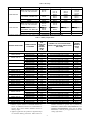
Table 1 – Kit Usage
KIT PART NO.
KGACA02014FC
FURNACE MODEL
FURNACE SIZE USED WITH
58STA / STX / DLA / DLX / CTA /
CTX / CVA / CVX / PHA / PHX
045--- 08
045--- 12
310 / 311 / 312 / 313 / 315AAV /
JAV PG8MAA / JAA /MEA / JEA
024045
036045
58YAV
393AAV
070--- 08
024070
135--- 16
135--- 20
135--- 22
048135
060135
066135
136--- 20
060135
58STA / STX / DLA / DLX / CTA /
CTX / CVA / CVX / PHA / PHX
KGACA02015FC
310 / 311 / 312 / 313 / 315AAV /
JAV PG8MAA / JAA / MEA / JEA
58YAV
393AAV
070--- 08
070--- 12
070--- 16
090--- 14
090--- 16
090--- 20
024070
036070
048070
070--- 12
036070
042090
048090
060090
091--- 14
042091
110--- 12
110--- 16
110--- 20
110--- 22
036110
048110
066110
111--- 16
048111
155--- 20
155--- 22
—
—
060155
066155
—
—
155--- 20
060155
—
—
—
—
The furnace and kit combinations are C.S.A. design--certified as ALTERNATIVE VENTING DESIGNS.
Table 2 – Chimney Requirements
FURNACE MODEL SIZES
CHIMNEY ADAPTER
KIT NUMBER
FURNACE
VENT
CONNECTOR
LATERAL
MAXIMUM
LENGTH
FT (M)
CHIMNEY CLAY TILE LINER MAXIMUM
NOMINAL SIZE OR INSIDE AREA IN OR IN2
(MM or MM2)
CHIMNEY
MAXIMUM
HEIGHT
FT (M)
MODELS 310 / 311 / 312 / 313 / 315AAV / JAV, 58STA / STX / PHA / PHX / DLA / DLX/ CTA / CTX/ CVA / CVX , PG8MAA / JAA / MEA / JEA
KGACA02014FC
9 (3)
8 X 8 or 42.7 (203 X 203 or 27548)
30 (9)
24045 / 045--- 08
KGACA02014FC
9 (3)
8 X 12 or 63.6 (203 X 305 or 41032)
25 (8)
KGACA02014FC
9 (3)
8 X 8 or 42.7 (203 X 203 or 27548)
30 (9)
036045 / 045--- 12
KGACA02014FC
9 (3)
8 X 12 or 63.6 (203 X 305 or 41032)
25 (8)
KGACA02014FC
9 (3)
8 X 8 or 42.7 (203 X 203 or 27548)
30 (9)
024070 / 070--- 08
KGACA02014FC
9 (3)
8 X 12 or 63.6 (203 X 305 or 41032)
25 (8)
KGACA02014FC
9 (3)
8 X 8 or 42.7 (203 X 203 or 27548)
30 (9)
036070 / 070--- 12
KGACA02014FC
9 (3)
8 X 12 or 63.6 (203 X 305 or 41032)
25 (8)
KGACA02014FC
9 (3)
8 X 8 or 42.7 (203 X 203 or 27548)
30 (9)
048070 / 070--- 16
KGACA02014FC
9 (3)
8 X 12 or 63.6 (203 X 305 or 41032)
25 (8)
042090 / 090--- 14
KGACA02014FC
9 (3)
8 X 12 or 63.6 (203 X 305 or 41032)
35 (11)
048090 / 090--- 16
KGACA02014FC
9 (3)
8 X 12 or 63.6 (203 X 305 or 41032)
35 (11)
060090 / 090--- 20
KGACA02014FC
9 (3)
8 X 12 or 63.6 (203 X 305 or 41032)
35 (11)
036110 / 110--- 12*
KGACA02014FC
9 (3)
8 X 12 or 63.6 (203 X 305 or 41032)
35 (11)
048110 / 110--- 16
KGACA02014FC
9 (3)
8 X 12 or 63.6 (203 X 305 or 41032)
35 (11)
060110 / 110--- 20
KGACA02014FC
9 (3)
8 X 12 or 63.6 (203 X 305 or 41032)
35 (11)
066110 / 110--- 22
KGACA02014FC
9 (3)
8 X 12 or 63.6 (203 X 305 or 41032)
35 (11)
048135 / 135--- 16*
KGACA02015FC
10 (3)
12 X 12 or 83.3 (305 X 305 or 53742)
35 (11)
060135 / 135--- 20*
KGACA02015FC
10 (3)
12 X 12 or 83.3 (305 X 305 or 53742)
35 (11)
066135 / 135--- 22*
KGACA02015FC
10 (3)
12 X 12 or 83.3 (305 X 305 or 53742)
35 (11)
060155 / 155--- 20*
KGACA02015FC
10 (3)
12 X 12 or 83.3 (305 X 305 or 53742)
35 (11)
066155 / 155--- 22*
KGACA02015FC
10 (3)
12 X 12 or 83.3 (305 X 305 or 53742)
35 (11)
MODELS 393AAV and 58YAV
KGACA02014FC
9 (3)
8 X 8 or 42.7 (203 X 203 or 27548)
30 (9)
024070 / 070--- 08
KGACA02014FC
9 (3)
8 X 12 or 63.6 (203 X 305 or 41032)
25 (8)
KGACA02014FC
9 (3)
8 X 8 or 42.7 (203 X 203 or 27548)
30 (9)
036070 / 070--- 12
KGACA02014FC
9 (3)
8 X 12 or 63.6 (203 X 305 or 41032)
25 (8)
042091 / 091--- 14
KGACA02014FC
9 (3)
8 X 12 or 63.6 (203 X 305 or 41032)
35 (11)
048111 / 111--- 16
KGACA02014FC
9 (3)
8 X 12 or 63.6 (203 X 305 or 41032)
35 (11)
060135 / 135--- 20
KGACA02015FC
10 (3)
12 X 12 or 83.3 (305 X 305 or 53742)
35 (11)
060155 / 155--- 20
KGACA02015FC
10 (3)
12 X 12 or 83.3 (305 X 305 or 53742)
35 (11)
*Chimney must be minimum height specified in the furnace installation instructions.
7. Maintain required clearance to combustible materials. See
furnace for Minimum--Clearances--to--Combustible--Construction label, which includes minimum clearance to
chimney adapter.
8. Appliance application and operation has significant impact
on successful chimney performance. Follow furnace in-
stallation instructions in general and, in particular, the
APPLIANCE APPLICATION REQUIREMENTS in the
VENTING REQUIREMENTS section. See the NFGC,
NSCNGPIC, or authority having jurisdiction for all other
venting requirements.
2
CHIMNEY INSPECTION CHART
For additional requirements refer to the National Fuel Gas Code NFPA 54/ANSI Z223.1-2006 and
NFPA 211-2006 Chimneys, Fireplaces, Vents and Solid Fuel Burning Appliances in the
U.S.A. or to the Canadian Installation Code CSA-B149.1-05 in Canada.
Crown condition:
Missing mortar
or brick?
Rebuild
crown
Yes
No
Is Chimney
property lined with
clay tile liner?
No
Yes
Is liner and
top seal in good
condition?
No
Repair liner or top
seal or reline
chimney as
necessary.
Yes
Debris in
cleanout? Mortar,
tile, metal vent, fuel
oil residue?
Repair
Yes
Yes
No
Chimney exposed
to outdoors below
roof line?
Remove mortar and
tile debris
No
Yes
No
Condensate
drainage at bottom
of chimney?
Yes
Mortar of
tile debris?
No Remove metal vent
or liner.
Clay tile
misalignment,
missing sections,
gaps?
Reline
Yes
Consult
Part B of
Not Suitable
chimney adapter venting
instructions for
No
application
suitability.
Is chimney lined
Suitable
with properly sized.
listed liner or
Yes
Type-B vent?
Install chimney
adapter per
instructions.
Not Suitable
Yes
Is chimney to be
dedicated to a
single furnace?
No
Consult
Part C of
chimney adapter
venting instructions
for application
suitability
Line chimney with properly
sized, listed flexible metal
liner or Type-B vent per
NFGC or NSCNGPIC Vent
Sizing Tables and liner or
vent manufacturer’s
Installation instructions.
Suitable
Install chimney
adapter per
instructions.
No
Chimney is
acceptable for use.
A08245
B. SINGLE FURNACE
(Single furnace without a draft hood--equipped water heater
vented into a chimney.)
1. The 99 percent winter design temperature* shall determine
permitted locations for clay tile -- lined masonry chimneys
as shown in Table 3 :
2. Type -- B double -- wall metal vent (with up to 4 elbows)
shall be used exclusively for furnace vent connector.
3. Furnace vent connector shall be same size as Chimney Adapter outlet.
4. See Table 2 for maximum length of furnace vent connector lateral.
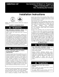
NOTE:
See Figure 1 while reviewing the following
requirements.
5. The minimum chimney size shall conform to Table 4.
6. See Table 2 for maximum chimney size and maximum
chimney height.
3
Table 3 – Permitted Chimney Location
MINIMUM 99% WINTER DESIGN TEMPERATURE*
--- 25°F (--- 32°C) or Warmer
+17°F (--- 8°C) or Warmer
PERMITTED CHIMNEY LOCATION
Interior Masonry Chimney{
Exterior Masonry Chimneys}
* The 99% Winter Design Dry ---Bulb (db) temperatures are found in the 2005 ASHRAE Fundamentals Handbook CD and Chapter 28. Figure G---19 in the NFGC
(Appendix G) also provides winter design temperatures for some locations.
{Chimneys not exposed to the outdoors below the roof ---line.
}Chimneys with one or more sides exposed to the outdoors below the roof line.
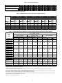
Table 4 – Single--Furnace -- Masonry Chimney Flue Capacity with Type--B Double--Wall Vent Connector
VENT
HEIGHT
H
FT (M)
6 (2)
8 (2)
10 (3)
15 (5)
20 (6)
30 (9)
35 (11)
LATERAL
L
FT (M)
2 (.6)
5 (2)
2 (.6)
5 (2)
8 (2)
2 (.6)
5 (2)
10 (3)
2 (.6)
5 (2)
10 (3)
2 (.6)
5 (2)
10 (3)
2 (.6)
5 (2)
10 (3)
2 (.6)
5 (2)
10 (3)
MINIMUM “NAT MAX’ INTERNAL AREA OF MASONRY CHIMNEY FLUE, SQUARE IN.
38
50
63
78
FURNACE INPUT RATING IN THOUSANDS OF BTU PER HOUR
NAT
NAT
NAT
NAT
NAT
86
130
180
247
320
82
117
165
231
298
93
145
198
266
350
88
134
183
247
328
83
127
175
239
318
103
162
221
298
388
96
148
204
277
365
87
139
191
263
347
114
179
250
336
441
107
164
231
313
416
97
153
216
296
394
124
201
274
375
491
116
184
254
350
463
107
172
237
332
440
137
216
303
421
558
128
198
281
393
526
115
184
236
373
500
143
168
315
435
577
134
206
291
406
544
121
192
273
386
517
28
95
NAT
401
376
446
423
410
491
466
444
562
513
567
627
597
566
717
83
48
741
706
669
NOTE: Table 4 was extracted from “NAT Max” columns in Table 13.1 in Chapter 13 of NFPA54/ANSI Z223.1 ---2006 in United States, or Table 1 of Appendix C in CAN/
CSA---B149.1 ---05 in Canada.
Table 5 – Permitted Vent Material
MINIMUM 99% WINTER
DESIGN TEMPERATURE*
--- 25°F (--- 32°C) to --- 10°
(--- 23°C)
CHIMNEY LOCATION
FURNACE VENT
CONNECTOR MATERIAL
Interior Masonry Chimneys{
Listed Type--- B Double--- Wall
Metal Pipe
Exterior Masonry Chimneys}
Interior Masonry Chimneys{
--- 10°F (--- 23°C) or Warmer
Exterior Masonry Chimneys}
Not Permitted
Listed Type--- B Double--- Wall
Metal Pipe or Single--- Wall Galvanized Steel Pipe
Listed Type--- B Double--- Wall
Metal Pipe
WATER HEATER VENT
CONNECTOR MATERIAL
Listed Type--- B Double--- Wall
Metal Pipe or Single--- Wall Galvanized Steel Pipe
Not Permitted
Listed Type--- B Double--- Wall
Metal Pipe or Single--- Wall Galvanized Steel Pipe
Listed Type--- B Double--- Wall
Metal Pipe or Single--- Wall Galvanized Steel Pipe
*The 99% Winter Design Dry ---Bulb (db) temperatures are found in the 2005 ASHRAE Fundamentals Handbook CD and Chapter 28. Figure G---19 in the NFGC
(Appendix G) also provides winter design temperatures for some locations.
{Chimneys not exposed to outdoors below roof ---line.
}Chimneys with 1 or more sides exposed to outdoors below roof ---line.
C. MULTIPLE APPLIANCES
(Single furnace common--vented with a draft hood--equipped
water heater(s) into a chimney.)
1. The minimum 99 percent winter design temperature* and
chimney location shall determine permitted vent connector
material as shown in Table 5:
2. Furnace vent connector rises shall not exceed 3 ft. (.9M)
3. An operational draft hood--equipped water heater shall be
common--vented with furnace. Additional draft hood-equipped appliances are permitted to be common--vented
with furnace.
4. Each vent connector is permitted up to 4 elbows.
5. Furnace vent connector shall be same size as Chimney Adapter outlet.
6. Water heater vent connector shall be 4--in. (102 mm)diameter with no more than 6 ft. (2 M) of lateral (horizontal
connector length), with water heater draft hood outlet sizes
of 3-- and 4--in. (76 and 102 mm) diameter. Use a 3-- X
4--in. (76 X 102 mm)vent increaser with a 3--in. (76 mm)
draft hood outlet.
7. Water heater gas inputs* shall not exceed the following
rates as shown in Table 6.
NOTE: See Fig. 1 while reviewing the following requirements.
4
Table 6 – Max Water Heater Input
VENT HEIGHT H --- FT (M)
1
4--- inch dia. (102 mm) Connector Rise R Ft.
(M)
Water Heater Maximum Input Rating in
Thousands of BTU per Hour
B
S
.3
40
39
6 (2)
2
1
8 (2.5)
2
3
1
.6 .9 .3
52 61 41
52 61 40
.6 .9
53 62
52 62
.3
42
41
3
10 (3)
2
3
1
.6 .9 .3
54 63 44
53 62 43
15 (4.5)
2
3
1
.6 .9 .3
55 64 46
54 63 45
20 (6)
2
3
1
30 (9)
2
3
1
50 (15)
2
3
1
100 (30)
2
3
.6 .9 .3
56 65 48
57 65 47
.6 .9
58 66
57 65
.3
51
50
.6 .9
61 69
60 68
.3
50
49
.6 .9
60 68
59 67
B=Listed Type ---B Double ---Wall metal pipe. S=Single ---Wall galvanized---steel pipe.
These rise requirements are based on NFGC and NSCNGPIC.
Table 7 – Minimum Masonry Chimney Internal Area (Multiple Appliances)
Vent Height
H
Ft. (M)
6 (2)
8 (2)
10 (3)
15 (5)
20 (6)
30 (9)
35 (11)
MINIMUM ”NAT+NAT” INTERNAL AREA OF MASONRY CHIMNEY FLUE, SQ. IN. (SQ. MM)
28 (18064)
38 (24516)
50 (32258)
63 (40645)
78 (50322)
113 (72903)
Combined Appliance Maximum Input Rating in Thousands of Btu per Hour
NAT
NAT
NAT
NAT
NAT
NAT
+NAT
+NAT
+NAT
+NAT
+NAT
+NAT
NP
103
143
188
246
NP
NP
119
163
218
278
408
NP
131
177
236
302
454
106
152
212
283
365
546
122
172
243
325
419
648
137
198
278
381
496
749
NP
NP
291
401
524
792
NP --- Not Permitted
Table 8 – Permitted Exceptions to Minimum 99% Winter Design Temperature and Furnace Connector Diameter
Chimney Clay Tile Liner Nominal Size or Inside Area
In. or Sq. In (mm or Sq. mm)
Furnace
8 x 8 or 42.7
8 x 12 or 63.6
12 x 12 or 83.3
Model
(203 x 203 or 27548)
(203 x 305 or 41032)
(305 x 305 or 53742)
Sizes
Furnace Type --- B Vent Connector Diameter In. (mm)
6 (152)
5 (127)
4 (102)
6 (152)
5 (127)
4 (102)
7 (178)
6 (152)
5 (127)
MODELS 310 / 311 / 312 / 313 / 315AAV / JAV and 58STA / STX / PHA / PHX / DLA / DLX / CTA / CTX / CVA / CVX and PG8MAA / JAA / MEA / JEA
024045 / 045 ---08
036045 / 045 ---12
024070 / 070 ---08
+5
---10
---10
036070 / 070 ---12
---10 ( ---23)‡‡
---10 ( ---23)
---10 ( ---23)
NP
NP
NP
(15)*
( ---23)**††
( ---23)*
048070 / 070 ---16
042090 / 090 ---14
---10
---10
048090 / 090 ---16
---10 ( ---23)††
NP
---10 ( ---23)††
NP
NP
NP
NP
( ---23)†
( ---23)†
060090 / 090 ---20
036110 / 110 ---12
048110 / 110 ---16
---10 ( ---23)‡
NP
NP
---10 ( ---23)‡
NP
NP
NP
NP
NP
060110 / 110 ---20
066110 / 110 ---22
048135 / 135 ---16
---10
---10
---10
---10
060135 / 135 ---20
NP
NP
NP
NP
NP
( ---23)*†,††
( ---23)*††
( ---23)††
( ---23)*
066135 / 135 ---22
060155 / 155 ---20
NP
NP
NP
NP
NP
NP
---10 ( ---23)‡
NP
NP
066155 / 155 ---22
MODELS 393AAV and 58YAV
024070 / 070 ---8
+5
---10
---10
---10 ( ---23)‡‡
---10 ( ---23)
---10 ( ---23)
NP
NP
NP
(15)*
( ---23)**††
( ---23)*
036070 / 070 ---12
---10
---10
042091 / 091 ---14
---10 ( ---23)††
NP
---10 ( ---23)††
NP
NP
NP
NP
( ---23)†
( ---23)†
048111 / 111 ---16
---10 ( ---23)‡
NP
NP
---10 ( ---23)‡
NP
NP
NP
NP
NP
---10
---10
---10
---10
060135 / 136 ---20
NP
NP
NP
NP
NP
( ---23)*†,††
( ---23)*††
( ---23)††
( ---23)*
060155 / 155 ---20
NP
NP
NP
NP
NP
NP
---10 ( ---23)‡
NP
NP
NP = Not Permitted
Temperatures in parentheses are Celsius temperatures.
* Furnace connector rise shall be at least 3 ft. (.9 M)
{Chimney height shall be at least 10 ft. A higher chimney height is required, if the furnace installation instructions specify a higher chimney height.
}Furnace connector rise shall be at least 2 ft or chimney height shall be at least 15 ft. (5 M)
** 6 ---in. X 5 ---in. (152 X 127 mm) or 6 ---in. X 4 ---in. (152 X 102 mm) tapered furnace vent connector decreaser is permitted at chimney inlet opening. However,
better resistance to chimney condensation will result, if connector diameter is not reduced.
{{4 ---in. X 3 ---in. (102 X 76 mm) tapered water heater vent connector decreaser is permitted at chimney inlet opening. However, better resistance to chimney
condensation will result, if connector diameter is not reduced.
}}Either ** or {{ is permitted, but not both.
5
8. Minimum chimney size shall conform to ”NAT+NAT”
columns for common vent capacity in Table 13.2c in
Chapter 13 of NFPA54/ANSI Z223.1--2006 in United
States, or Table C 7 of Appendix C of CAN/CSA-B149.1--05 in Canada. The chimney sizing requirements
in Table 7 (below) were extracted from these codes.
9. Permitted exceptions to --10_F (--23_C) minimum 99 percent winter design temperature and furnace connector diameters are provided in Table 8. If Table 8 permits a furnace connector size that is smaller than the chimney
adapter outlet, a tapered decreaser is permitted at the chimney adapter outlet.
10. Manifolded common--vent connectors: See Fig. G.1(k) in
NFPA54/ANSI Z223.1--2006 in USA or Fig. C.9 in CAN/
CSA--B149.1--05 in Canada. For chimney heights of 8 ft
or more, Type--B manifolded common--vent connectors
with no elbows are permitted. The manifolded common-vent connector diameter shall be 1 in. (25 mm) greater
than required furnace vent connector size. The combined
horizontal length of longest vent connector (furnace or
water heater) plus manifolded common--vent connector
shall not exceed vent connector lateral specified in section
A.6. Each connector is permitted up to 2 elbows. No exceptions from Table 8 are permitted. The minimum winter
design temperature permitted with manifolded common-vent connector is --10_F (--23_C).
5.
6.
INSTALLATION OF CHIMNEY ADAPTER
1. Turn off gas supply at manual gas valve before turning off
electric power supply to furnace.
2. Turn off electric power supply to furnace at disconnect
switch.
3. The chimney adapters must always be installed for vertical
flow of vent gas from bottom to top of chimney adapter.
AIR--FLOW
4. UPFLOW
AND
HORIZONTAL
APPLICATIONS NOT NEEDING STRAIGHT VENT
PIPE INTERNAL TO FURNACE (horizontal flow not
permitted with 393AAV/58YAV):
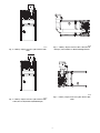
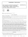
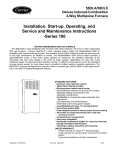
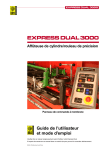
KIT NO. KGACA02014FC: Attach chimney adapter to
furnace flue elbow (collar on 393AAV/58YAV) with 2
sheet metal screws (field--supplied) through two 1/8--in. (3
mm) holes at inlet (small end) of chimney adapter. (See
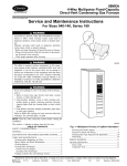
Fig. 2 or 3.) If a 1/8--in. (3 mm) hole at inlet is not accessible, remove three screws that hold elbow to inducer, attach chimney adapter to elbow, then reattach elbow to inducer (not applicable to 393AAV/58YAV).
KIT NO. KGACA02015FC: Use same procedure as
above, except a standard 4--in. dia. to 5--in. dia. (102 to
127 mm) vent pipe increaser (field--supplied) is required
between furnace elbow and chimney adapter.
(393AAV/58YAV: use 5--in. (127 mm) dia. X 12--in. (305
mm) long pipe, one end oval, instead of increaser.)
DOWNFLOW AND HORIZONTAL AIR--FLOW
APPLICATIONS HAVING A STRAIGHT VENT PIPE
INTERNAL TO FURNACE (not permitted with
393AAV/58YAV):
KIT NO. KGACA02014FC: Complete installation of
flue pipe (and elbows) to exit furnace casing. If downflow
furnace flue pipe exits casing through lower--left door
opening, route the flue pipe through an accessory vent
guard external to the casing. Attach chimney adapter to
furnace flue where it exits the furnace casing or vent guard
with three sheet metal screws (field--supplied) through two
factory--punched 1/8--in. (3 mm)holes and a third fielded-drilled 1/8--in. (3 mm) hole at inlet (small end) of chimney
adapter. Third hole should be 90_ from other two holes.
KIT NO. KGACA02015FC: Use same procedure as
7.
8.
9.
10.
6
above for KGACA02014FC, except a standard 4--in. dia.-to--5--in. (102 to 127 mm) dia. vent pipe increaser (field-supplied) is required between the furnace flue and the
chimney adapter.
Remove lock nut from fitting on free end of electrical conduit attached to chimney adapter. Route wire ends through
a 7/8--in. (22 mm) hole in furnace casing near the chimney
adapter. Secure conduit to furnace with lock nut. If Vent
Guard is used on downflow furnace, cut a notch in Vent
Guard flange to provide access to 7/8--in. (22 mm) hole in
furnace casing for conduit attachment.
See, Fig. 8--12 & 13 for wiring connections. Furnaces other than 393AAV.58YAV: Find furnace red wires that connect to draft safeguard switch (DSS). Disconnect red wire
with insulated, female, 3/16--in. (8 mm) quick--connect
terminal from DSS, and connect this red wire to orange
wire from blocked vent shutoff switch (BVSS) of chimney
adapter that has insulated, male, 3/16--in. (8 mm) quick-connect terminal. Male and female 3/16--in. (8 mm) terminals must be oriented so that insulators fit together.
Connect other chimney adapter BVSS orange wire to DSS
terminal from which red wire was disconnected. Position
orange wire terminal similar to remaining red wire terminal on DSS so that orange wire is directed away from hot
elbow. The BVSS should be in series with the DSS.
393AAV/58YAV furnaces: Find furnace orange wires that
connect to draft safeguard switch (DSS). DSS has 1/4--in.
(6 mm) quick--connect terminals. Without disconnecting
either orange wire at DSS, cut one of these wires about 3
in. (76 mm) from 1/4--in. (6 mm) terminal. Cut terminals
off free ends of both orange wires of chimney adapter
BVSS close to the terminals. Strip and splice the cut ends
of the orange wires in the furnace to the cut ends of the
orange wires of the chimney adapter BVSS with field-supplied wire nuts. The BVSS should be in series with the
DSS.
NOTE: For applications where the chimney adapter wire
leads will not reach the DSS, use the factory--supplied extension wires between the chimney adapter BVSS leads
and the DSS. A metal wire--routing clip is included in the
kit to secure the orange extension wires away from hot
surfaces and rotating parts. Extension wires are not applicable to 393AAV/58YAV.
No other wire connection changes should be made for
chimney adapter. Be certain that no terminals can be shorted to other circuits or to any grounded parts.
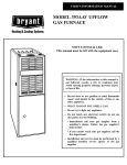
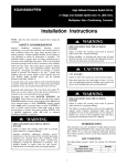
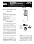
Refer to Fig. 1. Secure a Type--B draft hood connector to
top of chimney adapter with 3 sheet metal screws (field-supplied). Install Type--B double--wall metal vent connector from draft hood connector to chimney flue opening in
accordance with vent pipe manufacturer’s Installation Instructions. The horizontal portion of venting system shall
maintain a minimum of 1/4--in. upward slope per linear
foot away from furnace, and shall be rigidly supported
every 5 ft. or less with hangers and straps to ensure that
there will be no movement after installation. The connector shall conform to size, rise, and lateral requirements under Venting Requirements and Table 2 of these instructions. Do NOT use the NFGC or NSCNGPIC vent
connector sizing requirements.
Complete installation of water heater Type--B double--wall
vent connector in same manner as used for furnace connector, except that a chimney adapter is not required at
Type--B draft hood connector for water heater. (Not required for single appliance, Venting Requirements Section
B.)
START--UP, ADJUSTMENT, AND SAFETY
CHECK
nace chimney adapter, or leakage from vent system), the
common--venting chimney system must be corrected.
g. After it has been determined that each appliance properly
vents when tested as outlined above, return doors, windows, exhaust fans, fireplace dampers, and any other gas-burning appliances to their previous conditions of use.
2. Check chimney adapter BVSS. This test is required, in
addition to the test of the DSS required by the furnace installation instructions. The purpose of the BVSS is to
cause safe shutdown of furnace, if furnace vent connector
or chimney becomes blocked.
a. Disconnect power to furnace, and remove vent connector
from chimney adapter. Be sure to allow time for vent pipe
to cool down before handling pipe.
b. Place jumper wire across DSS terminals to electrically
by--pass DSS so that if DSS opens, furnace does not shutdown until BVSS opens.
c. Restore power to furnace and set room thermostat 5_F
(--15_C) above room temperature.
d. After normal start--up, allow furnace to operate for 2
minutes, then block chimney adapter outlet 100 percent.
Furnace should shut off within 2 minutes.
e. REMOVE JUMPER WIRE FROM DRAFT
SAFEGUARD SWITCH!
f. Remove blockage and reconnect vent connector to chimney adapter.
g. Wait 5 minutes, then reset BVSS and DSS.
3. With furnace blower operating, check for air leakage from
supply--air plenum or coil casing that could interfere with
BVSS operation. If air leaks are found they must be properly sealed.
4. Leave Installation Instructions for chimney adapter and for
furnace near furnace.
1. Complete Start--Up, Adjustment, and Safety Check in furnace Installation Instructions. Adjust furnace air temperature rise to be near high end of air temperature rise range
specified on furnace rating plate (without exceeding high
end of rise range). A higher air temperature rise reduces
chimney condensation. While doing furnace check, the
following steps shall be performed with each appliance
that is connected to common vented chimney. Put each appliance in operation while other appliance(s) are not in operation.
a. Inspect venting system for blockage or restriction, leakage, corrosion, and other deficiencies that could cause an
unsafe condition.
b. Insofar as practical, close all building doors and windows, and all doors between space in which appliances
are located and other spaces of building. Turn on clothes
dryer and any appliance not connected to this chimney
flue. Turn on all exhaust fans such as range hoods and
bathroom exhausts, so they will operate at maximum
speed. Do not operate a summer exhaust fan. Close fireplace dampers.
c. Follow operating instructions for each appliance being
checked. Adjust each thermostat so appliance will operate continuously.
d. Test for vent gas spillage at water heater draft hood (when
applicable) and at furnace chimney adapter relief openings after 5 minutes of main burner operation. Use the
flame of a match or candle.
e. Operate ALL appliances that are common--vent connected to chimney flue, and again test for vent gas spillage.
f. If improper venting is observed during any of above tests
(e.g., vent gas spillage at water heater draft hood or fur-
7
CONNECTOR
HORIZONTAL
LENGTHS
CLAY
TILE-LINED
MASONRY
CHIMNEY
TILE LINER SIZE
INSIDE
NOMINAL
(OUTSIDE)
CHIMNEY
HEIGHT
VENT
CONNECTOR
RISES
FURNACE
DIA
SINGLE
SINGLE WALL OR
TYPE-B
WALL OR
(SEE
TYPE-B
TABLE 5)
(SEE
TABLE 5)
WATER
HEATER
DIA
CHIMNEY
ADAPTER
DRAFT
HOOD-EQUIPPED
WATER HEATER
(NOT REQUIRED FOR
SINGLE APPLIANCE)
FAN-ASSISTED
FURNACE
A97515
Fig. 1 -- Furnace and Water Heater Vent Connectors, Chimney Adapter, and Chimney
4-IN. TO 5-IN.
DIA. VENT
PIPE
INCREASER
ON FLUE
COLLAR
2 SCREWS
180° APART TO
SECURE
CHIMNEY
ADAPTER TO
FURNACE
FLUE COLLAR
CONDUIT
BLOCKED
VENT
SHUTOFF
SWITCH
CHIMNEY
ADAPTER
OUTLET FOR
VENT
CONNECTION
2 SCREWS
180° APART
TO SECURE
VENT PIPE
INCREASER
TO FURNACE
FLUE COLLAR
CHIMNEY
ADAPTER
INLET AND
FURNACE
FLUE COLLAR
CONDUIT
3 SCREWS
120° APART
TO SECURE
CHIMNEY
ADAPTER INLET
TO VENT PIPE
INCREASER
BLOCKED
VENT
SHUTOFF
SWITCH
CHIMNEY
ADAPTER
OUTLET FOR
VENT
CONNECTION
NOTE: Conduit may need to be located at front of chimney
adapter to provide clearance to an evaporator coil casing.
A08191
A08192
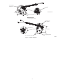
Fig. 2 -- Chimney Adapter Secured to Upflow Furnace Flue
Collar (Sizes up through 110,000 Btuh input)
Fig. 3 -- Chimney Adapter Secured to Upflow Furnace Flue
Collar (Sizes of 132,000 and 154,000 Btuh input)
8
A08196
A08193
Fig. 6 -- Chimney Adapter Secured to Flue Collar, Internal
Flue Pipe, and Vent Elbow on Horizontal--Right Furnace
Fig. 4 -- Chimney Adapter Secured to Upflow Furnace Flue
Collar
A08195
Fig. 7 -- Chimney Adapter Secured to Upflow Furnace Flue
Collar
A08194
Fig. 5 -- Chimney Adapter Secured to Upflow Furnace Flue
Collar (Sizes of 132,000 and 154,000 Btuh input)
9
A08064
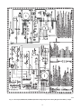
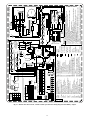
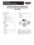
Fig. 8 -- 313AAV/JAV, 58PHA/PHX, PG8MEA/JEA Deluxe Single--Stage Furnace Wiring Diagram with Chimney Adapter
10
A08224
Fig. 9 -- Models other than 393AAV / 58YAV Standard Single--Stage Furnace Wiring Diagram with Chimney Adapter
11
12
L
E
G
E
N
D
EAC-1
SPARE 2
SPARE 1
GND
GV
GVR 1, 2
HSI
HSIR
HUM
IDM
IDR
ILK
J1
JB
LED
LGPS
BFANR
BHT/CLR
BLWR
BLWM
BVSS
CAP
CPU
DSS
EAC-1
EAC-2
FRS 1, 2
FSE
FU 1
FU 2
RED
START
BRN
2
YEL
ORN
CAP
GRN/YEL
PR1
PL2
WHT
BRN
RED
GRN/YEL
1
WHT
BLK
BLK
WHT
ILK
JB
DSS
RED
BLK
NOTE #11
WHT
BLK
GRN/YEL
IDM
BVSS
(WHEN USED)
ORG
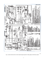
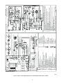
Fig. 10 -- Models other than 393AAV / 58YAV Deluxe Single--Stage Furnace Wiring Diagram with Chimney Adapter
13.
14.
EQUIPMENT GROUND
PLUG RECEPTACLE
FIELD SPLICE
FIELD EARTH GROUND
15.
10.
11.
12.
FIELD WIRING SCREW TERMINAL
PL2
CPU
24VAC
115VAC
COM 24V
FRS2
LS1
FSE
L2
IDM
EAC-2
NOTE #3
GV
PRS
NOTE #11
LS2
(WHEN USED)
NOTE #10
BVSS
(WHEN USED)
BLWM
DSS
START
LGPS
(WHEN USED)
FRS1
HSI
OL
CAP
SCHEMATIC DIAGRAM
(NATURAL & PROPANE GASES)
If any of the original equipment wire is replaced use wire rated for 105°C.
Use only copper wire between the disconnect switch and the furnace junction box (JB).
This wire must be connected to furnace sheet metal for control to prove flame.
Symbols are electrical representation only.
Solid lines inside PCB are printed circuit board conductors and are not included in legend.
Replace only with a 3 amp fuse.
Inducer (IDM) and blower (BLWM) motors contain internal auto-reset thermal overload switches (OL).
Neutral connections are interchangeable within the NEUTRAL connector block.
Blower motor speed selections are for average conditions, see installation instructions for details on
optimum speed selection.
Factory connected when BVSS (Chimney Adapter Accessory Kit) is not installed.
Factory connected when LGPS is not used.
Ignition-lockout will occur after four consecutive unsuccessful trials-for-ignition. Control will
auto-reset after three hours.
Blower-on delay: gas heating 25 seconds, cooling or heat pump 2 seconds.
Blower-off delay: gas heating selections are 90, 120, 150 or 180 seconds, cooling or heat pump
90 seconds or 5 seconds when DHUM is ON.
YELLOW lead not on all motors.
PL1-7
PL1-9
PL1-11
PL1-3
PL1-5
PL1-10
PL1-1
GVR-1
PL1-4
PL1-2
PL1-8
PL1-6
2
1
COM
LO
MED LO
MED HI
HI
PL3
SPARE-1
NOTE #15
COOL
HEAT
EQUIPMENT GROUND
G
GVR-2
SEC-2
2
1
BHT/CLR
PCB NOTE #5
TEST/TWIN
NOTE #6
SEC-1
TRAN
PR1
EAC-1
HSIR
FAN
L2 NEUTRAL
BFANR
Y1
DHUM
Y/Y2
W
R
HUM
NOTES:
1.
2.
3.
4.
5.
6.
7.
8.
9.
IDR
BLWR
L1
ILK
FU1
L1
TO 115VAC FIELD DISCONNECT SWITCH
CONDUCTOR ON CONTROL PCB
FIELD WIRING (24VAC)
FIELD WIRING (115VAC)
FACTORY WIRING (24VAC)
FACTORY WIRING (115VAC)
PCB CONTROL TERMINAL
UNMARKED TERMINAL
LIMIT SWITCH, AUTO-RESET, SPST(N.C.)
AUTO-RESET INTERNAL MOTOR OVERLOAD
TEMPERATURE SWITCH (N.C.)
PRINTED CIRCUIT BOARD CONTROL
11-CIRCUIT PCB CONNECTOR
2-CIRCUIT CONNECTOR
2-CIRCUIT HSI, CONNECTOR
PRESSURE SWITCH, SPST-(N.O.)
COMPONENT TEST & TWIN TERMINAL
TRANSFORMER-115VAC/24VAC
JUNCTION
GND
FUSE OR CIRCUIT BREAKER &
DISCONNECT SWITCH (WHEN REQ’D)
NOTE #2
NEUTRAL
WHT
FU2
L1
BLK
WHT
WHT
RED
(WHEN USED)
RED
LS2
NOTE #10
ORG
LS1
(WHEN USED)
LGPS
RED
FRS2
BLK
PCB
PL1
PL2
PL3
PRS
TEST/TWIN
TRAN
LS 1, 2
OL
1
2
RED
BLU
FRS1
RED
PL3
PRS
WHT (COM)
FSE
RED
NOTE #5
GRN/YEL
GV
NEUTRAL
CONNECTION DIAGRAM
CONTINUOUS-FAN SELECT RELAY, SPDT
BLOWER MOTOR SPEED CHANGE RELAY, SPDT
BLOWER MOTOR RELAY, SPST-(N.O.)
BLOWER MOTOR, PERMANENT-SPLIT-CAPACITOR
BLOCKED VENT SHUTOFF SWITCH, MANUAL-RESET, SPST -(N.C.)
CAPACITOR
MICROPROCESSOR AND CIRCUITRY
DRAFT SAFE GUARD SWITCH, AUTO-RESET, SPST -(N.C.)
ELECTRONIC AIR CLEANER CONNECTION (115 VAC 1.0 AMP MAX.)
ELECTRONIC AIR CLEANER CONNECTION (COMMON)
FLAME ROLLOUT SW. -MANUAL RESET, SPST-(N.C.)
FLAME-PROVING ELECTRODE
FUSE, 3 AMP, AUTOMOTIVE BLADE TYPE, FACTORY INSTALLED
FUSE OR CIRCUIT BREAKER CURRENT INTERRUPT DEVICE
(FIELD INSTALLED & SUPPLIED)
EQUIPMENT GROUND
GAS VALVE-REDUNDANT
GAS VALVE RELAY, DPST-(N.O.)
HOT SURFACE IGNITER (115 VAC)
HOT SURFACE IGNITER RELAY, SPST-(N.O.)
24VAC HUMIDIFIER CONNECTION (0.5 AMP. MAX.)
INDUCED DRAFT MOTOR, SHADED-POLE
INDUCED DRAFT MOTOR RELAY, SPST-(N.O.)
BLOWER ACCESS PANEL INTERLOCK SWITCH, SPST-(N.O.)
BLOWER - OFF DELAY JUMPER SELECTOR
JUNCTION BOX
LIGHT-EMITTING DIODE FOR STATUS CODES - AMBER
LOW GAS PRESSURE SWITCH, SPST-(N.O.)
RED (LO)
NOTE #15
YEL
(MED HI)
OL
L1
FAN
HEAT
BLWM
BLWR
BLK (HI)
BLU
PL1
BFANR
L2
BHT/CLR
COOL
BLU
(MED LO)
WHT
(COM)
LED
SEC-1
EAC-2
SEC-2
HUM
TEST/TWIN
R
Y/Y2
180
J1
120
1 2 3 4 5 6 7 8 9 10 11
150
90
G
Com
24V
W
DHUM
FU1
NOTE #6
NOTE #8
TRAN
Y1
NEUTRAL
BLW
PCB
HSI
YEL
PRINTED CIRCIUT BOARD
327560-101 REV. D
BLOWER OFF-DELAY
JUMPER SELECT OR
PRINTED CIRCIUT BOARD
A02140
A08225
Fig. 11 -- Models other than 393AAV / 58YAV Two--Stage Furnace Wiring Diagram with Chimney Adapter
13
PRINTED CIRCIUT BOARD
14
1
AB CD
PL7
OFF
123
OFF
123
OFF
123
AC
Y1 DHUM G Com W/W1 Y/Y2 R
24V
Air Conditioning (Adjustable Airflow -CFM)
Air Conditioning Relay, SPST (N.O.)
Air Conditioning Relay Defeat Jumper
Blower Motor (ECM)
Blocked Vent Safety Switch, Manual Reset,
SPST (N.C.)
CF
Continuous Fan (Adjustable Airflow -CFM)
COMMR Communication Relay, SPDT
CPU
Microprocessor 7 Circuitry
DHUM DHUM Connection (24VAC 0.02 Amps)
DSS
Draft Safeguard Sw., Auto-Reset, SPST (N.C.)
EAC-1 Electronic Air Cleaner Connection
(115VAC 1.0 Amp Max.)
EAC-2 Electronic Air Cleaner Connection (Common)
FRS
Flame Rollout Switch, Man. Reset, SPST(N.C.)
FSE
Flame-Proving Sensor Electrode
FUSE
Fuse, 3 Amp, Automotive Blade Type,
Factory Installed
GV
Gas Valve
GVR
Gas Valve Relay, DPST (N.O.)
HPS
High-Heat Pressure Switch, SPST (N.O.)
HPSR
High-Heat Pressure Switch Relay, SPST (N.C.)
HSI
Hot Surface Igniter (115VAC)
HSIR
Hot Surface Igniter Relay, SPST (N.O.)
HUM
24VAC Humidifier Connection (0.5 Amp Max.)
HUMR Humidifier Relay, SPST (N.O.)
IDM
Inducer Draft Motor, 2-Speed, Shaded Pole
IDR
Inducer Motor Relay, SPST (N.O.)
IHI/LOR Inducer Motor Speed Change Relay, SPDT
W2
OFF
A/C
ACR
ACRDJ
BLWM
BVSS
PL1
OFF
123
1
1 CF
1
4
1
OFF
123
1
YEL
LPS
RED
NOTE #13
NEUTRAL - L2
BLK
L1
PL2
WHT
DSS
ORN
1
BLK
WHT
WHT
WHT
BLU
PL12
IND
NOTE #7
BLK
4
BLK
WHT
COM
HI
BLWM
PL10
HSI
PL14
ILK
JB
GRN/YEL
CONDUCTOR ON
WIRING (24VAC)
FIELD CONTROL
WIRING (24VAC)
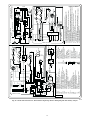
Fig. 12 -- Models other than 393AAV / 58YAV Variable--speed Furnace Wiring Diagram with Chimney Adapter
PLUG RECEPTACLE
GROUND
EQUIPMENT
SCREW TERMINAL
FIELD WIRING
CONTROL
RED
R
COMMR
HUM
13.
14.
11.
12.
10.
2
NOTE #5
PCB
IHI/LOR
BVSS
CPU
HUMR
GVR
HPSR
DSS
PL12
10
16
1
7
PL1-6
2
1
PL14
EAC-2
4
PL1-1
NOTE #3
C
PL1-10 M
GV
LGPS
(WHEN USED)
PL1-3
PL1-4
FU1
HI
HPS
LPS
IDM
L2
24VAC
TRAN
FSE
PL1-5
SEC1
SEC2
115VAC L2
BLWM
L1
NOTE #6
NOTE #8
PL1-2
PL1-12
PL1-8
FRS1
5
3
PL13
PL11
3 COM
LO
HI
4
HSI
PL10
2
1
2
1
SCHEMATIC DIAGRAM
1
2
3
EAC-1
PL2
EQUIPMENT
GROUND
IND
NOTE #7
PCB
4
L2
HSIR
L2
(WHEN USED)
NOTE #12
PL12
3
CPU
ACR
EAC
L1
1
(WHEN USED)
LS2
IDR
NOTE #5
PL3
ILK
TO 115VAC FIELD-DISCONNECT SWITCH
If any of the original equipment wire is replaced use wire rated for 105∞C.
Use only copper wire between the disconnect switch and the furnace junction box (JB).
This wire must be connected to furnace sheet metal for control to prove flame.
Symbols are electrical representation only.
Solid lines inside PCB are printed circuit board conductors and are not included in legend.
Replace only with a 3 amp fuse.
Inductor is used with 3/4 hp and 1 hp ECM Blower motors.
Factory connected when (LGPS) not used.
Blower off-delay, gas heating selections are (90, 120, 150, 180) seconds, cooling or heat pump
90 seconds or 5 seconds when dehumidify call is active.
Ignition lockout will occur after four consecutive unsuccessful trials for ignition. Control will
auto-reset after three hours.
Inducer motor (IDM) contains internal auto-reset thermal overload switch.
Factory connected when BVSS is not used. BVSS used when Chimney Adapter Accessory Kit is
installed.
Any of the 5 wires shown within the NEUTRAL L2 box can be connected to any terminal within the box.
Blower motor (BLWM) is locked-rotor overload protected by redundant electronic control circuits.
NOTES:
COM
Y/Y2
G
Y1
DHUM
W2
1.
2.
3.
4.
5.
6.
7.
8.
9.
LS1
GND
W/W1
FRS2
PRINTED CIRCIUT BOARD
FACTORY CONTROL
WIRING (115VAC)
FACTORY POWER
CONTROL TERMINAL
TERMINAL
JUNCTION
FRS2
BLK WHT
FU2
54 3 2 1
2
1
LO
GRN/YEL
RED
FUSED OR CIRCUIT
BREAKER DISCONNECT
SWITCH (WHEN REQ'D)
NOTE #2
NEUTRAL
L1
LS1
10 16 1 7
PL13
BLK
RED
BLK
RED
2
BLK
ORN
IDM
PL11 WHT
3
WHT
RED
FSE
RED
LS2
(WHEN USED)
RED
LGPS (WHEN USED)
BVSS
(WHEN USED)
NOTE #8
ORN
NOTE #12
Blower Door Interlock Switch, SPST (N.O.)
Inductor (Note #7)
Light Emitting Diode for Status Codes
Low Gas Pressure Switch, SPST (N.O.)
Low-Heat Pressure Switch, SPST (N.O.)
Limit Switch, Auto-Reset, SPST (N.C.)
Printed Circuit Board
12-Circuit Connector
4-Circuit HSI & IDM Connector
4-Circuit ECM BLWM Connector
4-Circuit Model Plug Connector
4-Circuit Communication Connector
2-Circuit OAT Connector
2-Circuit HSI Connector
IDM Connector (3-Circuit)
1-Circuit Inductor Splice Connector
16-Circuit ECM Blower Ctrl. Connector
5-Circuit ECM Blower Power Connector
Manual Switch, Status Code Recall, SPST (N.O.)
Manual Switch, Low-Heat Only, SPST(N.O.)
Manual Switch, Low-Heat Rise Adj. SPST (N.O.)
Manual Switch, Comfort/Efficiency Adjustment,
SPST (N.O.)
SW1-5 Manual Switch, Cooling CFM/Ton, SPST (N.O.)
SW1-6 Manual Switch, Component Test, SPST (N.O.)
SW1-7,8 Manual Switches, Blower Off-Delay, SPST(N.O.)
SW4-1 Manual Switch, Twinning Main (OFF) / Sec. (ON)
SW4-2&3 FOR FUTURE USE
TRAN Transformer, 115VAC / 24VAC
ILK
IND
LED
LGPS
LPS
LS 1, 2
PCB
PL1
PL2
PL3
PL4
PL7
PL9
PL10
PL11
PL12
PL13
PL14
SW1-1
SW1-2
SW1-3
SW1-4
STATUS
CODE
LEDS
COMM
MODEL
SIZE
875 1050 1 1225 1225 1225
070
DEF. 525 2 700
525
700 2 875 1050 1225 1400 1 1400
090
DEF.
110,135,
700
875 2 1050 1225 1400 1750 1 2100
DEF.
155
1. Default A/C airflow when A/C switches are in OFF position
2. Default cont. fan airflow when CF switches are in OFF position
HUM
PL9
PL3
GRN/YEL
BRN
GRY
RED
OFF
123
FUSE 3-AMP
FRS1
123
SEC-2 SEC-1
A/C OR CF AIRFLOW SELECTION CHART BASED ON 350 CFM/TON
PL8
HI
BRN
HPS
BLU
PL12
L
E
G
E
N
D
NOTE #3
C
GRN/YEL
GV
PL4 - MODEL PLUG CHART
MODEL MODEL PIN RESISTANCE K
PLUG
SIZE
1-4
2-3
HK70EZ
11
5.1
070
001
24
5.1
090
003
5.1
33
110
004
39
5.1
135
005
51
5.1
155
006
90
SEC
120
SEC
150
SEC
180
SEC
M
CONNECTION DIAGRAM
OFF
123
ACRDJ
EAC-1
SW1-7,8
BLOWER OFF DELAY
SELECTION
RED
GRN
YEL
BLU
EAC-2
OAT
YEL
PL4
SW1
VS HSI HI LO
OFF OFF OFF OFF
SW4
327562-101 REV. C
7 8 7 8 7 8 7 8
RED
GRN
YEL
BLU
ACRDJ
TRAN
A02160
Fig. 13 -- 393AAV / 58YAV Single Stage Furnace Wiring Diagram with Chimney Adapter
A00304
15
GV
GVR
HI/LO
HSI
HSIR
HUM
IDM
IDR
ILK
JB
LED
LGPS
LS
OL
ALS
BLWR
BLWM
BVSS
CAP
CPU
DSS
EAC-1
EAC-2
FL
FRS
FSE
FU1
FU2
1
HSI
2
1
2
PL5
PL2
PL3
SEC-2
6 5 4
9 8 7
3 2 1
SEC-1
PL1
LED
1
2
3
BLK
WHT
COM
PR2
L2
IDM
GRN/YEL
EAC-2
HEAT SPARE-2
EAC-1
24 VAC-3A
FU1 FUSE
BLOWER
SPEED COOL SPARE-1
SELECT
HI/LO
RELAY
BLWR
GVR
225 SEC
180 SEC
135 SEC
TEST/TWIN
HUM
G
R
Y
W
COM
BLU
WHT (COM)
RED (LO)
BLU (MED LO)
NOTE #7
YEL (MED HI)
WHT
FRS1
FSE
LS
ORN
ILK
OL
BRN
BRN
GND
WHT
BLK
FU2
NEUTRAL
L1
FUSED DISCONNECT
SWITCH (WHEN REQ’D)
NOTE #4
CAP
GRN/YEL
WHT (COM)
WHT
BLK
PLUG RECEPTACLE
FIELD SPLICE
EQUIPMENT GROUND
FIELD GROUND
FIELD WIRING TERMINAL
CONDUCTOR ON PCB
FIELD WIRING (24VAC)
FIELD WIRING (115VAC)
FACTORY WIRING (24VAC)
FACTORY WIRING (115VAC)
PCB TERMINAL
UNMARKED TERMINAL
JUNCTION
YEL
GRN/YEL
NOTE #5
GV
NOTE #15
NOTE #13
(WHEN USED)
LGPS
PRINTED CIRCUIT BOARD
9-CIRCUIT CONNECTOR
2-CIRCUIT PCB CONNECTOR
3-CIRCUIT IDM CONNECTOR
2-CIRCUIT HSI/PCB CONNECTOR
PRESSURE SWITCH, SPST-(N.O.)
COMPONENT TEST & TWIN TERMINAL
TRANSFORMER-115VAC/24VAC
JB
BLWM
START
PCB
PL1
PL2
PL3
PL5
PRS
TEST/TWIN
TRAN
BLK
RED
BLU
FL
PRS
FRS2
GRN/YEL
ORN
(WHEN USED)
NOTE #11
ALS
(WHEN USED) NOTE #11
NOTE #14
ORN
(WHEN USED)
NOTE #14
BVSS
ORN
BLK (HI)
RED
WHT
RED
ORN
DSS
AUXILIARY LIMIT SWITCH, OVERTEMP. -MANUAL RESET, SPST-(N.C.)
BLOWER MOTOR RELAY, SPST-(N.O.)
BLOWER MOTOR
BLOCKED VENT SHUTOFF SWITCH, SPST - (N.C.)
CAPACITOR
MICROPROCESSOR AND CIRCUITRY
DRAFT SAFEGUARD SWITCH
ELECTRONIC AIR CLEANER CONNECTION (115 VAC 1.5 AMP MAX.)
ELECTRONIC AIR CLEANER CONNECTION (COMMON)
FUSIBLE LINK
FLAME ROLLOUT SW. -MANUAL RESET, SPST-(N.C.)
FLAME PROVING ELECTRODE
FUSE, 3 AMP, AUTOMOTIVE BLADE TYPE, FACTORY INSTALLED
FUSE OR CIRCUIT BREAKER CURRENT INTERRUPT DEVICE
(FIELD INSTALLED & SUPPLIED)
GAS VALVE-REDUNDANT OPERATORS
GAS VALVE RELAY, DPST-(N.O.)
BLOWER MOTOR SPEED CHANGE RELAY, SPDT
HOT SURFACE IGNITOR (115 VAC)
HOT SURFACE IGNITOR RELAY, SPST-(N.O.)
24VAC HUMIDIFIER CONNECTION (.5 AMP. MAX.)
INDUCED DRAFT MOTOR
INDUCED DRAFT RELAY, SPST-(N.O.)
BLOWER ACCESS PANEL INTERLOCK SWITCH, SPST-(N.O.)
JUNCTION BOX
LIGHT-EMITTING DIODE FOR STATUS CODES
LOW GAS PRESSURE SWITCH, SPST-(N.O.)
LIMIT SWITCH, AUTO RESET, SPST(N.C.)
AUTO-RESET INTERNAL MOTOR OVERLOAD TEMP. SW.
LEGEND
BLK
IDR
BLK
120 VAC
L1 PR1
HSIR
BLK
90 SEC
BLOWER OFF DELAY
SELECTION CHART
NOTE #9
(NOT ON ALL MODELS)
WHT
PCB
WHT
SW2
BLOWER
OFF
DELAY SW1
1.5 AMP
TRAN
L1
HSIR
IDR
CPU
BLWR
GVR-2
SEC-1
TRAN
PR1
EAC-2
EAC-1
PL2
HI/LO
GVR-1
GVR
SEC-2
24VAC
PR2
PL1
9 NOT USED
CAP
FL
(WHEN USED)
NOTE #14
BVSS
FSE
NOTE #5
GV
ALS
(WHEN USED)
NOTE #13
PRS
LGPS
(WHEN USED)
LS
FRS2
IDM
BLWM
START
NOTE #14
NOTE #15
DSS
NOTE #13
(WHEN USED)
NOTE #11
FRS1
NOT USED
OL
6 NOT USED
5
8
2
3
4
1
7
2
3 PL3
HSI
LO
MED LO
MED HI
HI
COM
1
2
1
NOTE #7
2 PL5
1
COM
COOL
SPARE-1
115VAC
HI/LO
SPARE-2
HEAT
EQUIPMENT GROUND
SCHEMATIC DIAGRAM
(NATURAL GAS & PROPANE)
L2
1. If any of the original equipment wire is replaced use wire rated for 105°C.
2. Inducer (IDM) and blower (BLWM) motors contain internal auto-reset thermal overload switches (OL).
3. Blower motor speed selections are for average conditions, see installation instructions for details on
optimum speed selection.
4. Use only copper wire between the disconnect switch and the furnace junction box (JB).
5. This wire must be connected to furnace sheetmetal for control to detect flame.
6. Replace only with a 3 amp fuse.
7. Yellow lead not on all motors.
8. Blower-on delay, gas heating 45 seconds, cooling or heat pump 2 seconds.
9. Blower-off delay, gas heating 90, 135, 180 or 225 seconds, cooling or heat pump 90 seconds.
(135 seconds only on some models)
10. Ignition-lockout will occur after four consecutive unsuccessful trials-for-ignition. Control will auto-reset
after three hours.
11. When used, auxiliary limit switch (ALS) is on some downflow models only. When used, FL is on
upflow models only.
12. Some models may have spade quick connect terminals.
13. Factory connected when LGPS is not used.
14. Factory connected when BVSS is not used. BVSS used when Chimney Adapter Accessory Kit is
installed.
15. Gas valve leads are interchangeable on single stage valves.
322869-101 REV. H
NOTES:
COM
G
Y
W
R
NOTE #12
HUM
FU1
IDR
HSIR
BLWR
NOTE #6
L2
NOTE #4
TEST/TWIN
ILK
L1
TO 115VAC FIELD DISCONNECT
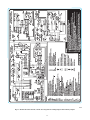
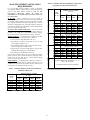
MASONRY CHIMNEY APPLICATION
REQUIREMENTS
17 to 26_F (--- 8 to
--- 3_C)
VENT
HEIGHT
FT. (M)
6 (1.8)
8 (2.4)
10 (3)
15 (5)
20 (6)
30 (9)
--- 10 to 4_F (--- 23
to --- 16_C)
6 (2)
8 (2)
10 (3)
15 (5)
20 (6)
30 (9)
INTERNAL AREA OF CHIMNEY
IN.2 (mm2)
12
(7742)
19
(12258)
28
(18064)
38
(24516)
Local 99% Winter Design Temperature:
17 to 26_F (--- 8 to --- 3_C)*
0
55
99
141
52
74
111
154
NR
90
125
169
NR
NR
167
212
NR
NR
212
258
NR
NR
NR
362
Local 99% Winter Design Temperature: 5
to 16_F (--- 15 to --- 9_C)*
NR
78
121
166
NR
94
135
182
NR
111
149
198
NR
NR
193
247
NR
NR
NR
293
NR
NR
NR
377
Local 99% Winter Design Temperature:
--- 10 to 4_F (--- 23 to --- 16_C)*
NR
NR
145
196
NR
NR
159
213
NR
NR
175
231
NR
NR
NR
283
NR
NR
NR
333
NR
NR
NR
NR
Local 99% Winter Design Temperature: --- 11_F or
lower (--- 24_C or lower)*
Not recommended for any vent configuration
*The 99% Winter Design Dry ---Bulb (db) temperatures are found in the
2005 ASHRAE Fundamentals Handbook CD and Chapter 28.
Table 9 – Combined Appliance Maximum Input Rating in
Thousands of Btu per Hr
VENT
HEIGHT
FT (M)
6 (2)
8 (2)
10 (3)
15 (5)
20 (6)
30 (9)
6 (2)
8 (2)
10 (3)
15 (5)
20 (6)
30 (9)
--- 11_F or lower
(--- 24_C or lower)
If a clay tile--lined masonry chimney is used, an alternative
venting design might be required, such as a listed chimney lining
system or this listed chimney adapter kit. ONE OF THE
FOLLOWING METHODS SHALL BE USED TO
DETERMINE IF AN ALTERNATIVE VENTING DESIGN IS
NOT REQUIRED.
In the USA -- Refer to Sections 13.1.11 and 13.2.22 of
NFPA54/ANSI Z223.1--2006 or the authority having jurisdiction
to determine whether relining is required. If relining is required,
use a properly sized listed metal liner, Type--B vent, or a listed
alternative venting design, such as this listed chimney adapter kit
(with a furnace listed for use with this kit), a listed chimney lining
system, or a Type--B common vent.
In Canada (Also permitted in the USA) -- A 78 or 80 percent
AFUE, hot surface ignition, Category I, fan--assisted furnace is
permitted to be vented into a clay tile--lined masonry chimney
that is exposed to the outdoors below the roof line, provided:
Multiple Appliances -- (A single furnace common--vented with
a draft hood--equipped water heater(s) into a chimney.)
1. Vent connector is Type--B double--wall, and
2. The furnace is common vented with at least one draft
hood--equipped appliance, and
3. The combined appliance input rating is less than the maximum capacity given in Table 9A, and
4. Input rating of each space heating appliance is greater than
minimum input rating given in Table 9B and
5. The authority having jurisdiction approves.
If all of these conditions cannot be met, an alternative venting
design is required, such as this listed chimney adapter kit (with a
furnace listed for use with this kit), a listed chimney lining
system, or a Type--B common vent.
Single Appliance -- (A single furnace vented into a chimney.) -Category I, fan assisted furnaces without draft hoods are not
permitted to be vented into clay tile--lined masonry chimneys that
are exposed to the outdoors below the roof line.
Table 10 – Minimum Allowable Input Rating of Space--Heating Appliances in Thousands of Btu per Hr
INTERNAL AREA OF CHIMNEY
IN.2 (mm2)
12
19
28
38
(7742)
(12258)
(18064)
(24516)
74
119
178
257
80
130
193
279
84
138
207
299
NR
152
233
334
NR
NR
250
368
NR
NR
NR
404
16
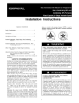
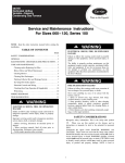
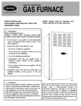
7-IN. (179 mm)
DIA OUTLET
RESET SWITCH
7 3/4″ (197 mm)
5-IN. (127 mm) INLET
KGACA02015FC
1/8-IN. (3 mm) DIA. HOLES
6-IN. (152 mm)
DIA. OUTLET
RESET SWITCH
8 1/4″ (209 mm)
1/8-IN. (3 mm) DIA. HOLES
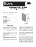
4-IN. (102 mm) INLET
A08240
Fig. 14 -- Chimney Adapters
17
SERVICE TRAINING
Packaged Service Training programs are an excellent way to increase your
knowledge of the equipment discussed in this manual, including:
• Unit Familiarization • Maintenance
• Installation Overview • Operating Sequence
A large selection of product, theory, and skills programs is available, using popular
video-based formats and materials. All include video and/or slides, plus companion
book.
Classroom Service Training plus "hands-on" the products in our labs can mean
increased confidence that really pays dividends in faster troubleshooting, fewer
callbacks. Course descriptions and schedules are in our catalog.
CALL FOR FREE CATALOG 1-800-644-5544
[ ] Packaged Service Training [ ] Classroom Service Training
A94328
Copyright 2008 CAC / BDP D 7310 W. Morris St. D Indianapolis, IN 46231
Printed in USA.
Edition Date: 04/08
Manufacturer reserves the right to change, at any time, specifications and designs without notice and without obligations.
18
Catalog No: IIK---KGACA ---01
Replaces: AG--GACA--06