1
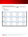
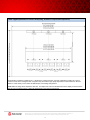
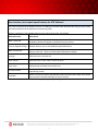
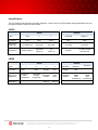
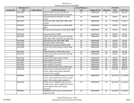
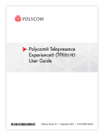
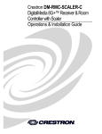
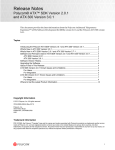
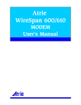
Technical Specifications Polycom® Architected Telepresence Experience™ ATX™ | ATX SDK There are two distinct software solutions for the ATX platform, The ATX and the ATX Software Development Kit (SDK). The SDK is a set of tools that enable a certified ATX partner to customize the user interface and add additional device and room controls to an overall telepresence solution. ATX software, when loaded on a specified touch panel controller and touch panel, provides a functional user interface that has the same feature set as the Polycom OTX 300 and the TPX 306M. It is important to note that the ATX SDK and ATX software solutions have some different and unique feature sets. Solution Components ATX 300 ATX 300 ATX 200 ATX 400 Available for SDK Solutions only 1 Polycom HDX 8000 video codecs supporting 1080p/30fps or 720p/60fps 3 3 2 4 Polycom HDX Ceiling Microphone Arrays 3 3 3 3 Eagle Eye II cameras (silver) 3 3 2 4 Telepresence software Telepresence configuration tool Documentation Set including: Integrator’s Guide, Customizable Quick Reference Card, User Guide FrameMaker source files, & Wiring Specifications Touch panel control system software - - - - - Similar functionality may be programmed by integrator Similar functionality may be programmed by integrator Similar functionality may be programmed by integrator Touch panel programming control modules GUI reference code/samples 2 Meeting Composer and Polycom CMA directory integration support 2 1 The HDX software for ATX is different from the HDX software for ATX SDK. You cannot use the HDX software for ATX version with ATX SDK or vice versa, so be sure to download the correct software for your site. 2 Download via touch panel controller vendor web site Updated October 2010 1 H.264 High Profile Bandwidth Requirements Support for the following data rates with QoS enabled, bidirectional, with a 50% burst increase within 100ms window. Bandwidth estimates are based on network traffic in one direction and do not include overhead and management traffic. Performance Packet loss < 0.1% End to end latency <150 ms Packet jitter < 40 ms ATX 200 Frame Rate Minimum Recommended Maximum 1080p30 High Profile 3 Mbps per suite 6 Mbps per suite 12 Mbps per suite 720p60 High Profile 3 Mbps per suite 6 Mbps per suite 12 Mbps per suite Frame Rate Minimum Recommended Maximum 1080p30 High Profile 4.5 Mbps per suite 9 Mbps per suite 18 Mbps per suite 720p60 High Profile 4.5 Mbps per suite 9 Mbps per suite 18 Mbps per suite Frame Rate Minimum Recommended Maximum 1080p30 High Profile 6 Mbps per suite 12 Mbps per suite 24 Mbps per suite 720p60 High Profile 6 Mbps per suite 12 Mbps per suite 24 Mbps per suite ATX 300 ATX 400 Note: Two and Four screen/codec solutions (ATX SDK 200 & 400) are available using the ATX SDK only ©2010 Polycom, Inc. All rights reserved. Polycom and the Polycom logo design are registered trademarks of Polycom, Inc. All other trademarks are the property of their respective owners. Information is subject to change without notice. 2 H.264 Bandwidth Requirements (not High Profile) ATX 200 Frame Rate Minimum Recommended 1080p30 9 Mbps per suite 18 Mbps per suite 720p60 6 Mbps per suite 12 Mbps per suite Frame Rate Minimum Recommended 1080p30 9 Mbps per suite 18 Mbps per suite 720p60 6 Mbps per suite 12 Mbps per suite Frame Rate Minimum Recommended 1080p30 12 Mbps per suite 24 Mbps per suite 720p60 8 Mbps per suite 16 Mbps per suite ATX 300 ATX 400 Note: Two and Four screen/codec solutions (ATX SDK 200 & 400) are available using the ATX SDK only ©2010 Polycom, Inc. All rights reserved. Polycom and the Polycom logo design are registered trademarks of Polycom, Inc. All other trademarks are the property of their respective owners. Information is subject to change without notice. 3 LAN Connection Requirements The supported LAN wiring option for the ATX include: Home runs for ATX and the Touch Panel Control For voice add-on, you will need to supply an analog line. Voice add-on is necessary to enable access to a VNOC or other help desk. ATX Default Network Configuration Required LAN connections The ATX solution needs the following number of 100/1000BASE-T network connections, on RJ-45 connectors as well as static IP addresses. HDXs Touch Panel Controller Total 2 1 3 3 1 4 4 1 5 Note: Two and Four screen/codec solutions (ATX SDK 200 & 400) are available using the ATX SDK only Room Size Requirements Width Depth Ceiling Height (min) Minimum Recommended Minimum Recommended Minimum Recommended ATX 200 18 ft (5.5m) 24 ft (7.3m) 13 ft 6 in (4.11m) 15 ft (4.6m) 8 ft (2.4m) 8ft 8 in (2.7m) ATX 300 18 ft (5.5m) 24 ft (7.3) 13 ft 6 in (4.11m) 15 ft (4.6) 8 ft (2.4m) 8ft 8 in (2.7m) ATX 400 28 ft (8.5 m) 34 ft (10.4m) 13 ft 6 in (4.11m) 15 ft (4.6m) 8 ft (2.4m) 8ft 8 in (2.7m) ©2010 Polycom, Inc. All rights reserved. Polycom and the Polycom logo design are registered trademarks of Polycom, Inc. All other trademarks are the property of their respective owners. Information is subject to change without notice. 4 Floor Layout (Guidelines to achieve best quality, Immersive Telepresence Experience) The information provided is a guideline only. It will allow for a highly immersive, real-size, telepresence solution for a typical conference room with a rectangular table. Integrators may also achieve high quality telepresence solutions based on the ATX platform in a wide variety of room sizes and table shapes, and seating arrangements. Please note: The image above depicts the ATX 300. The depth of the room and the distance from the display to the back of the table are true for all three products. Width will adjust based on the solution implemented. ©2010 Polycom, Inc. All rights reserved. Polycom and the Polycom logo design are registered trademarks of Polycom, Inc. All other trademarks are the property of their respective owners. Information is subject to change without notice. 5 Power for Polycom supplied components Standby In Use (Max call rate with Content and Document sharing) Maximum (will not exceed) ATX 200 200W 200W 250W ATX 300 300W 300W 375W ATX 400 400W 400W 500W Important: This calculation includes ONLY the components supplied as part of the Polycom ATX 300 Solution. The total power consumption will need to be recalculated by the integrator to include components that complete the solution. Environmental Conditions Conference room operating temperature 41-86° F, 5-30° C Relative humidity 20% to 80% (non-condensing) Sound Pressure Level NC18 to NC25, Maximum 40 dBA level Non-Operating / Storage Constraints Non- operating temperature 32-104° F, 0-40° C Relative humidity 10% to 90% (non-condensing) Regulatory Compliance CE Marking FCC Part 15 Class A ©2010 Polycom, Inc. All rights reserved. Polycom and the Polycom logo design are registered trademarks of Polycom, Inc. All other trademarks are the property of their respective owners. Information is subject to change without notice. 6 User Interface (touch panel specifications) for ATX Software* The color Touch Panel is the interface for ATX*. It enables you to place video and audio calls, hang up calls, control the audio and perform other telepresence conferencing tasks. Below is a summary of the available tasks you may control via the color Touch Panel. Button/Function Description Make a video call The user has the ability to dial manually or speed dial. There are 18 speed dial buttons available (9 buttons will appear on the home screen at a time.) Previous Page/Next Page Buttons allow the user to view additional speed dial buttons Make an audio call Use the audio call button to make an audio only call or to add in an audio participant during a video call. There are 4 audio speed dial buttons available. Hang Up Allows the user to end the call Audio Control Allows the user to raise, lower or mute the audio Audio Level Horizontal bar indicating current audio level Content indicator Icon, when lit, indicates the far end is sharing content; also allows the user to start and stop sharing content Help Desk Button set up by the system administrator to place an audio call to assist users should they experience technical difficulties or have a question. *Buttons and functions for ATX SDK users will vary depending on integrator design ©2010 Polycom, Inc. All rights reserved. Polycom and the Polycom logo design are registered trademarks of Polycom, Inc. All other trademarks are the property of their respective owners. Information is subject to change without notice. 7 Integrator Supplied Components Guidelines to achieve best quality, immersive telepresence experience. Display Table Minimum requirements Touch Panel and Controller for ATX 58” - 65” Bezels on right and left side of display no larger than 3” Each display must have an HDMI input Display must have a Sleep or Standby setting ATX 200 ATX 300 ATX 400 115 in. 171 in. 227 in. 292.1 cm 434.3 cm 576.6 cm Crestron TPS-4000 10.4” tilt touch panel and TPS-IMPC (touch panel interface module) Crestron AV2 control system and C2ENET-1 Ethernet interface expansion card Touch Panel and Controller for ATX SDK Contact Crestron and AMX for current list of supported systems Content Display VGA 1024x768 input signal Speakers Polycom Stereo Speaker Kit (or equivalent) Omnimount universal speaker mounting bracket (recommended for wall mounting speakers) Non-Polycom components, furniture, and services to provide a complete solution Other ©2010 Polycom, Inc. All rights reserved. Polycom and the Polycom logo design are registered trademarks of Polycom, Inc. All other trademarks are the property of their respective owners. Information is subject to change without notice. 8 Inputs/Outputs The ATX supports the following input/output definitions. Please refer to the ATX System Wiring Specification found on the Partner Resource Center for more details. AUDIO Inputs Outputs Label AUX 3 4 VCR/DVD Monitor 1 Connector RCA RCA 3.5mm RCA RCA Signal Type Supported Line/Mic level Line level Line level Line level Line level Association Always mixed in VCR/DVD (Video 3) PC (Video 4) All audio All audio except mics and aux VIDEO Inputs Label 1 Connector HDCI Signal Type Supported Composite S-Video Component Association Outputs 2 3 4 VCR/DVD Monitor 1 HDCI S-Video DVI-I S-Video DVI-I Composite S-Video Component Composite S-Video VGA DVI-d Composite S-Video DVI HDMI VGA Component Audio 3 Audio 4 ©2010 Polycom, Inc. All rights reserved. Polycom and the Polycom logo design are registered trademarks of Polycom, Inc. All other trademarks are the property of their respective owners. Information is subject to change without notice. 9 Monitor 2 DVI-I DVI HDMI VGA Component