1
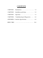
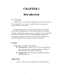
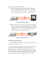
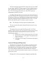
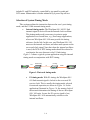
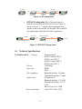
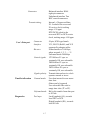
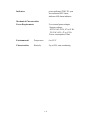
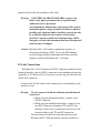
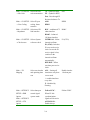
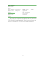
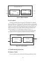
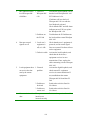
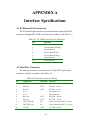
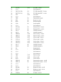
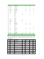
Atrie
WireSpan 600/610
MODEM
User's Manual
WireSpan 600 / 610
Fractional E1 Access Unit
Installation and Operation manual
CONTENTS
CHAPTER 1
Interduction………………………….. 1-1
CHAPTER 2
Installation and Setup………………..
2-1
CHAPTER 3
Operation…………………………….
3-1
CHAPTER 4
Troubleshooting & Diagnostics……..
4-1
APPENDIX A Interface Specification………………. A-1
MENU TREE
………………………………………. B-1
CHAPTER 1
Introduction
1.1
Overview
WireSpan 600 is a cost-effective, single-port fractional E1 access unit.
The fractional E1 service makes unused time slots on long-range E1
trunks available for other users.
WireSpan 600 provides a synchronous data channel that supports
user-selectable transmission rates. The available data rates are integer
multiples of 64 kbps; the multiples range is 1 through 32, corresponding to
a maximum of 2048 kbps. The user’s payload data is packed in the
corresponding number of time slot of an E1 (CEPT 2.048 Mbps) data
stream, for transmission over public or private E1 networks.
Versions
WireSpan 600 is available on two models:
z WireSpan 600 – fractional E1 access unit, for applications
that integer multiples of 64kbps range from 1 through 32,
corresponding to a maximum of 2048 kbps.
z WireSpan 610 – Unframed only, for applications that fix
2048M bps data rate.
Applications
Figure 1-1 shows a typical WireSpan 600 / 610 applications
1-1
E1Transmission
Transmission
E1
Facilities
Facilities
N x 64K
Rounte
r
Router
N x 64K
Converter
WireSpan 600
Rounte
Router
r
Converter600
WireSpan
RxDRXD
N x 64K
Terminal
Terminal
WireSpan 600
Converter
N x 64K
FE1
WireSpan 600
Converter
E1 MUX.
E1
Mux.
Sub-E1
DSL Line
Rounte
WireSpan
r 3000
N x 64K
WireSpan 600
Converter
TXD
Converter
WireSpan 600
TxD
WS5000B(LAN)
LAN
WireSpan
WireSpan
5000B5000V
V.35 Version
N x 64K
WireSpan 600
Converter
Cascades mode
Cascaded
PBX
PBX
Figure 1-1. Typical Wirespan 600 Application
Features
z
z
z
z
z
z
z
z
E1 or fractional E1 access unit
Support one digital data port
Selectable sync data rates of n x 64 kbps,up to 2048 kbps
V.35, RS-530, RS-449 or X.21 data interfaces
Framing format : PCM31, PCM30 – with or without
CRC-4
Zero suppression : AMI, HDB3
E1 interface complies with : ITU G.703, G.704, G.732,
G.823, G.706
Unframed over E1
Options
WireSpan 600 is available with the following option:
z 90 – 120 or 230V( 10%),47-63 Hz Adapter
z DTE or DCE data port changeable cable
z WireSpan 610 is simple version with unframed mode
1.2
Physical Description
WireSpan 600 / 610 are designed for desktop installation.
Installation procedures for the WireSpan 600 / 610 models and respective
versions are provided in Chapter 2, Installation and Setup.
1-2
Top Panel
LED’s
The LED indicators on the top panel (see Figure 1-2) indicate the
operating status of WireSpan 600. Various indicators display status of E1
or data port, alert conditions, work mode.
Figure 1-2. General View
Connectors
The power and interface connectors are located on the lateral panel of
WireSpan 600 / 610. A description of the lateral panel can be found in
interfaces and connectors.
1.3
Functional Description
WireSpan 600 / 610 has a synchronous user’s data port interface. The
electrical interface is user-selectable. The user’s data port is terminated in
a 50-pin SCSI-type female connector. ITU-T Rec. V.35, EIA RS-530,
RS-449 and X.21 interfaces are supported by means of adapter cables.
1-3
The user’s data port has two timing modes:
z DCE – WireSpan 600 provides transmit and receive clocks for
the user’s equipment connected to the data port. And accepts
XTC clock from the equipment. Figure 1-3 shows the flow of
timing signals through the user’s data port in the DCE mode.
TXC
RXC
XTC
WireSpan 600/610
DTE
Figure 1-3 DCE Description
z DTE – WireSpan 600 sends the receive data accompanied by the
receive clock to the user’s equipment connected to the data port,
and accepts data from the equipment according to the equipment
transmit clock. Figure 1-4 shows the flow of timing signals
through the user’s data port in the DTE mode.
TXC
RXC
XTC
WireSpan 600/610
DCE
Figure 1- 4 DTE Description
E1 Interface Characteristics
The WireSpan 600 E1 link interface meets the requirements of ITU-T
Rec. G.703, G.704, G.706, G .823.
The E1 link has two line interfaces: a 120-ohm balanced line interface
terminated in a RJ-48 eight-pin female connector, and a 75-ohm
unbalanced interface terminated in two BNC female coaxial connectors.
Line coding is HDB-3 or AMI. The nominal balanced interface transmit
level is ±3V, and the unbalanced interface transmit level is ±2.37V. Jitter
performance complies with the requirements of ITU-T Rec. G.823.
1-4
The E1 link interface supports PCM 31 frames (time slot 16 available
for user’s data), and PCM 30 frames (time slot 16 not available for user’s
data). WireSpan 600 also supports the CRC-4 option specified in ITU-T
Rec. G.704. The framing mode and the use of the CRC-4 option are
independently selectable by the user.
In addition, WireSpan 600 can also operate in the unframed mode. In
this mode, WireSpan 600 / 610 operates as an interface converter, enabling
the transfer of unstructured 2.048 Mbps data streams (or data streams with
proprietary framing generated by equipment with ITU-T Rec. V.35, EIA
RS-530, EIA RS-449), and X.21 interfaces via the E1 network.
Note
The WireSpan 610 always operates in unframed mode.
The user can select the number of main link time slots used to carry
the payload data.
The timing of the receive path of the Wirespan 600 / 610 E1 link
interface is always locked to the clock signal recovered from the received
line signal. The timing of transmit path can be locked to one of the
following three sources:
z
Internal clock oscillator, having an accuracy of ±30 ppm
z
The recovered receive clock signal. The maximum track
range is ±130 ppm
z
Lock data port clock signal. The maximum track range is
±100 ppm
Control of WireSpan 600 Operation
WireSpan 600 is designed for fully automatic, unattended operation.
Its configuration is determined by keypads and LCD-menu. Top panel
LED indicators and LCD display show the operating status of WireSpan
600. Various indicators display the E1 link status and user’s data port
status, and alert when an alarm condition (major or minor) or test loops are
present in the system.
WireSpan 600 / 610 has comprehensive diagnostic capabilities that
1-5
include LL and DL loopbacks, controlled by top panel keypads and
LCD-menu. Maintenance is further enhanced by a power-up self-test.
Selection of System Timing Mode
This section explains the interaction between the user’s port timing
mode, and the E1 link transmit timing mode.
z
Internal timing mode: The WireSpan 600 / 610 E1 link
transmit signal is derived from the internal clock oscillator.
This timing mode used is necessary in point-to-point
application over leased lines, e.g., short-range applications,
where one WireSpan 600 / 610 must provide the timing
reference for the link. In this case, one WireSpan 600 / 610
must use the internal oscillator, and other must operate on the
recovered clock signal. Note that when the internal oscillator
is used, the DCE or DTE timing mode should be selected to
synchronize the user data rate to the E1 link timing.
Figure 1-5 shows a typical system application using the internal
timing mode on conjunction with DCE timing.
N X.21
x 64K
DTE / DCE
Internal Timing
E1 Timing
E1
RS-449
WireSpan 600
Converter
WireSpan 600
DTE / DCE
Figure 1-5 Internal timing mode
z
E1 timing mode: With E1 timing, the WireSpan 600 /
610 link transmit signal is locked to the recovered E1
receive clock. This is usually the timing mode selected
for network operation, as shown in Figure 1-6. In the
application illustrated in Figure 1-6, the master clock of
the network determines the timing of the two WireSpan
600 / 610 units. In case the E1 receive signal is lost,
WireSpan 600 / 610 automatically switches to the
internal oscillator.
1-6
E1 Timing
E1 Timing
NV.35
x 64K
E1
V.35
N x 64K
E1
E1 Network
DTE / DCE
WireSpan 600
WireSpan 600
DTE / DCE
Figure 1-6 E1 timing mode
z
DTE/DCE timing mode: The E1 transmit signal is
locked to the recovered DTE or DCE receive clock, as
shown in Figure 1-7. And the other equipments must
operate on the recovered E1 clock signal. This is usually
the timing mode selected for E1-Mux. application.
EIA-530
DTE/DCE WireSpan 600
E1 Timing
E1
Converte
r
DTE/DCE Timing
V.35
E1 M UX.
Converte
WireSpan
600
r
Figure 1-7 DTE/DCE timing mode
1.4
Technical Specifications
E1 Link Interface
Unframed mode
PCM31 without CRC-4
PCM31 with CRC-4
PCM30 without CRC-4
PCM30 with CRC-4
2.048 Mbps
HDB3
AMI
Balanced interface 120 ohms
Unbalanced interface 75 ohms
Transmit level:
Balanced interface ±3V ±10%
Unbalanced interface ±2.37V
±10%
Receive level 0 to -36dB
As per ITU-T Rec. G.823
Framing
Bit rate
Line code
Line impedance
Signal levels
Jitter performance
1-7
Connectors
Balanced interface RJ-48
eight-pin connector
Unbalanced interface Two
BNC coaxial connectors
Internal- ±30 ppm oscillator
E1- Locked to the recovered
E1 receive clock, tracking
range ±130 ppm
DTE/DCE-Locked to the
recovered DTE or DCE receive
clock, tracking range ±100 ppm
Transmit timing
User’s Data port
Connector
Interface
Bit rates
Control signals
Signals polarity
TimeSlot allocation
Framed modes
Unframed mode
Diagnostics
Test loops
1-7
50-pin, SCSI-type female
V.35, RS-530,Rs-449, and X.21
supported by adapter cables
Framed modes-n X 64 kbps,
where n equals 1, 2, 3, ...., 31
Unframed mode-2048 kbps
CTS follows E1 sync or
constantly ON, user-selectable
DSR follows E1 sync or
constantly ON, user-selectable
DCD follows E1 sync or
constantly ON, user-selectable.
Transmit data and receive clock
operates normal or invert
User data inserted in user assert
time slots
Others can be bypassed
User-selectable idle code in
empty time slots (7F or FF)
Bit-by-bit transfer from data port
to E1 link
Local loopback (LL), towards
local DTE or DCE
Digital loopback (DL), towards
local E1 link
power indicator SYNC E1 sync
loss indicator BPV alarm
indicator AIS alarm indicator
Indicators
Mechanical Characteristics
Use external power adapter
Support voltage:
90-120 VAC±10%, 47 to 63 Hz
230 VAC±10%, 47 to 63 Hz
Power consumption 5Watt
Power Requirements
Environmental
Temperature
0 to 50°C
Characteristics
Humidity
Up to 90%, non-condensing
1-8
CHAPTER 2
Installation and Setup
2.1 General
This chapter provides instructions for mechanical and electrical
installation of the WireSpan 600 /610 model.
After installing the unit, refer to Chapter 3, Operation for operating
instructions. In case a problem is encountered, refer to Chapter 4
Troubleshooting & Diagnostics for test and diagnostics instructions.
Warning: No internal setting, adjustment, maintenance, and
repairs may be performed by either the operator or the
user; such activities may be performed only by a skilled
technician who is aware of the hazards involved. Always
observe standard safety precautions during installation,
operation, and maintenance of this product.
2.2 Site Requirements & Prerequisites
AC powered WireSpan 600 / 610 units should be installed within an
easily accessible, grounded AC outlet capable of furnishing the nominal
supply voltage (100-115 or 230 VAC, in accordance with your order).
The ambient operating temperature of WireSpan 600 / 610 is 0 to 50°C
at a relative humidity of up to 90%, non-condensing
2.3 Package Contents
A preliminary inspection of the equipment container should be made
before unpacking. Evidence of damage should be noted and reported
immediately. The WireSpan 600 / 610 package includes the following
items:
z WireSpan 600 unit or Wirespan 610 unit
2-1
z
z
z
CD disk or Installation and Operation Manual
External power adapter
Data port connection cable depending on user order
2.4 Equipment Needed
The cables you need depend on the application. Cable terminated in
appropriate connectors provides support for the following data port
interfaces:
z V.35 interface: the interface adapter cable ends in a
34-pin connector
z RS-530 interface: the interface adapter cable ends in
a 25-pin D-type connector
z RS-449 interface: the interface adapter cable ends in
a 37-pin D-type connector
z X.21 interface: the interface adapter cable ends in a
15-pin D-type connector
The required cables are available from ATRIE, or can be prepared in
accordance with the port connector wiring information given in Appendix
A, Interface Specifications. The available cable and their respective uses
are listed in Table 2-1
Table 2-1. Data Port Interface Cables
Purpose
Cable
Cable Connector User
End-Type
Equipment
M34 Female
V.35 DTE
M34 Male
V.35 DCE
Length
V35T
V35C
Port
Interface
V.35 DCE
V.35 DTE
530T
530C
449T
449C
EIA-530 DTE DB-25 Female
EIA-530 DCE DB-25 Male
RS-449 DTE DB-37 Female
RS-449 DCE DB-37 Male
EIA-530 DTE
EIA-530 DCE
RS-449 DTE
RS-449 DCE
1 meter
1 meter
1 meter
1 meter
X21T
X.21 DTE
DB-15 Female
X.21 DTE
1 meter
X21C
X.21 DCE
DB-15 Male
X.21 DCE
1 meter
1 meter
1 meter
2.5 Interfaces and Connections
Both the WireSpan 600 and WireSpan 610 versions use the same
2-2
printed circuit board, the procedure is the same.
Warning : ELECTRICAL SHOCK HAZARD: Access to the
inside of the unit is permitted only to qualified and
authorized service personnel.
Any adjustment, maintenance, and repair of the opened
instrument under voltage should be avoided as much as
possible and, when inevitable, should be carried out only
by a skilled technician who is aware of the hazard
involved. Capacitors inside the instrument may still be
charged even after the instrument has been disconnected
from its source of supply.
Caution WireSpan 600 / 610 contains components sensitive to
electrostatic discharge (ESD). To prevent ESD damage,
avoid touching internal components and before moving
jumpers, touch the WireSpan 600 / 610 frame.
E1 Link Connections
WireSpan 600 / 610 E1 link has an RJ-48C eight-pin connector for the
balanced interface, and two BNC connectors for the unbalanced interface.
Appendix A, E1 Balanced Port Connector provides the pin allocation for
the RJ-48C connector.
Connector the E1 link cables to the connector(s) corresponding to the
interface in use.
Warning
Do not connect to both the balanced and unbalanced
connectors!
z When using the balanced interface, connect to the
RJ-48C connector
z When using the unbalanced interface, connect to the
two BNC connectors designated TX and RX. Pay
attention to the correct connection of the receive and
transmit cables to the TX and RX connectors.
The maximum allowable line attenuation between the
WireSpan 600 E1 link port and the network interface is
2-3
1000 Ft / 26AWG in general case.
Data Port Connections
The Wirespan 600 / 610 user data port has a 50-pin SCSI-type female
connector.
Connect the DTE / DCE link cable to the SCSI connector after setting
pin-out configuration corresponding to the interface in use.
Connecting the Power
WireSpan 600 / 610 is available in models that differ in the rated
supply voltage: 120, 230 or 240 VAC.
Before first-time installation, check that the power-adapter nominal
supply voltage, marked on a label on its top panel, matches the nominal
voltage available at your mains outlet.
2.6 Setup
After Installation, You must be to check below list:
z The Power LED indicator always lights when
WireSpan 600 / 610 is powered.
z The LCD Display will warming-up after 10 seconds.
To configure setting the WireSpan 600 use keypads and LCD on top
panel as shown in Figure 2-1. The settings are listed in Table 2-2. You can
follow the rules below table to setup the WireSpan 600.
2-4
Figure 2-1. WireSpan 600 / 610 Top Panel View
Identification
of Setting
Table 2-2 Settings
Function
Settings
Main→ E1 SETUP Select E1 Frame
→ Framing
operating mode
PCM31 - CCS
without CRC4
PCM31+CRC - CCS
with CRC4
PCM30 - CAS
without CRC4
PCM30+CRC - CAS
with CRC4
2-5
Factory
Setting
PCM31
Main→ E1 SETUP Selects the idle
7F – Symbol in HEX.
→ Idle Code
FF – Symbol in HEX.
Pass –Pass through E1
Rx timeslot data to Tx.
code transmission
Main→ E1 SETUP Select E1 port
AMI
→ Line Coding
HDB3
coding, frame
structure
Main→ E1 SETUP Selection of E1
→Impedance
link interface
BNC – unbalanced 75
ohms interface
Pass
HDB3
RJ48C
RJ48C – balanced
120 ohms interface
Main→ E1 SETUP Selects System
→Clock source
reference clock
INTERNAL - follow
internal oscillator
E1 (G703)
E1 (G703) –locked to
E1 recovered receive
clock. In case the E1
receive signal is lost,
switches to the
internal oscillator
automatically.
DTE/DCE –follow
user data port receive
clock.
Main→ TS
Mapping
Select use timeslot
and operating data
ALL – Setting all
timeslot to carry data
rate
or non-used.
Enable timeslot
1 for data port
*- enable timeslot to
carry data
F– inhabited by
Framing
Main→ DTE/DCE
SETUP→DSR
Select data port
control signal
Follow SYNC –
When E1 link
Option
Main→ DTE/DCE
SETUP→CTS
Option
operate mode
synchronization,
signals will be active
ALWAYS ON –
Enable always
2-6
Follow SYNC
Main→ DTE/DCE
SETUP→DCD
Option
Main→ DTE/DCE
SETUP→ Clock
Polarity
Main→ DTE/DCE
SETUP→ Data
Select data port
timing mode
NORM – normal
operate mode
NORM
INV – Invert data port
receive clock or
transmit data
Polarity
After setting any configuration with WireSpan 600 /610, the internal
NVRAM will save setting immediately. When occur power down-to–up
process, the Wirespan 600 / 610 will recover setting automatically.
2-7
CHAPTER 3
Operation
3.1 General
In this chapter you will find detailed operating instructions for the
WireSpan 600 / 610 versions.
The information presented in this chapter includes:
z Description of indicators and LCD screens.
z Operating procedures
Refer to Chapter 4, Troubleshooting & Diagnostic and
troubleshooting instructions.
3.2 Indicators
Figure 3-1 and Figure 3-2 illustrates the top panel of WireSpan 600 /
610.
Figure 3-1 WireSpan 600 panel
3-1
Figure 3-2 WireSpan 610 panel
Table 3-1 lists the functions of the controls and indicators located on
the top panel of the WireSpan 600 / 610. The index number in Table 3-1
correspond to the item numbers in Figure 3-1 and Figure 3-2.
Table 3-1
N
Control or Indicator
Function
1
2
3
PWR indicator
SYN indicator
BPV indicator
Lights when WireSpan 600 / 610 is powered
Lights when the E1 link port synchronization
Lights when one or more bipolar violations
detected on E1 link receiver.
4
AIS indicator
5
Left, Right, Enter, Exit
Lights when two consecutive double frames
each contain two or fewer zeros out of 512 bits,
and when framing alignment is lost.
When depressed, activates the LCD screen to
6
7
8
buttons
BNC / RJ48C indicator
INT / E1 / DTE(DCE)
DL / LL
move to next by your choose.
Lights to indicate E1 link port selected
Lights to indicate clock sources selected
Lights to indicate loopback selected, if clean to
9
Impedance button
10
Clock Source button
operate in normal case
When depressed, changes setting between BNC
and RJ48C.
When depressed, changes the Clock reference
source. Keep to depress will to change into next
mode.
3-2
11
Loopback button
When depressed, activates LL / DL / Normal
cycle.
3.3 Operating Instructions
WireSpan 600 / 610 are designed for unattended operation. After
settings are completed, WireSpan 600 / 610 operates automatically.
Connect the AC power adapter to the mains outlet, the WireSpan 600 /
610 powered on automatically. Initially, WireSpan 600 / 610 performs a
self-test. Observe the following top-panel indicator:
z During the self-test, all the WireSpan 600 / 610
indicators should illuminate: confirm that all are
operating
z During the test second step, all the indicators except
PWR must blinks
z Following the test, all the indicators except PWR
WireSpan 600 / 610 are now ready for operation.
Normal Indications
During normal operation, the PWR and SYN indicators must light.
All the other indicators must be off.
Fault Indications
If a fault occurs, the BPV and/or AIS alarm indicators light, and data
transfer may be interrupted. To obtain additional information, observe the
state of the LCD screens and then refer to Troubleshooting Instructions for
troubleshooting information.
3.4 LCD displays
The following sections describe the major options of the menu tree.
Please refer to Appendix B for detail structure of the menu tree.
Not: The section provide with WireSpan 600 unit only
3-3
Main Menu
E1-E1 PCM31
RJ48C V35T 1984K
E1: First E1 indicates the operate mode. Other includes LL or DL
When operates loopback function.
E1: Second E1 indicates reference clock sources such as INT or DTE.
PCM31: To indicate the E1 link framing type
RJ48C: To indicate the E1 link interface type such as BNC.
V35T: To indicate the user data port cable type such as below list
z V35T: SCSI-V35 Female cable, to connect V.35
DTE equipment and default setting.
z V35C: SCSI-V35 Male cable, to connect V.35
DCE equipment.
z 530T: SCSI-EIA 530 Female cable, to connect
EIS-530 DTE equipment.
z 530C: SCSI-EIA 530 Male cable, to connect
EIS-530 DCE equipment.
z 449T: SCSI-RS 449 Female cable, to connect
RS-449 DTE equipment.
z 449C: SCSI-RS 449 Male cable, to connect
RS-449 DCE equipment.
z X21T: SCSI-X21 Female cable, to connect X.21
DTE equipment.
z X21C: SCSI-X21 Male cable, to connect X.21
DCE equipment.
1984K: To indicate data port data rate.
TimeSlots mapping menu
TS00-07 31:1984K
ALL [F*******] 01
TS00-07: To indicate the screen timeslot range
31: total assigned timeslots
1984K: user data port data rate (equal = total timeslots x 64K bps)
ALL: all timeslots(by framing type) are assigned or dis-assigned.
Note
When framing is PCM31, the timeslot 0 is inhibited. Its
3-4
means TS 0 cannot be assigned by user. When framing is
PCM30, the timeslot 0 and 16 are inhibited. When
unframed mode, all timeslot can assigned by user.
F: Inhibited timeslot (Framing Used )
*: user assign carry data timeslots
01: To indicate the cursor position timeslot number
E1 Link port alarm status
E1 STATUS
LOF:* YEL:* CRC:*
LOF: Receive loss of frame alignment
YEL: Receive yellow alarm
CRC:When use frame mode with CRC, Receive error
CRC-4 code
*: Error or loss occurs
Data port control signals status
Control Signals
CTS:* RTS:* DCD:*
Control Signals
DSR:* DTR:*
*: activates
3-5
CHAPTER 4
Troubleshooting & Diagnostics
4.1 General
This chapter presents information related to the Wirespan 600 / 610
diagnostics functions. The information presented in this chapter include:
z User-controlled test functions
z Troubleshooting
4.2 User-Controlled Test Functions
Loopback Function
The user-controlled test functions are activated by means of the
buttons and LCD screen.
Digital Loopback
Pressing Loopback button on top panel of WireSpan 610 or find the
function in Menu-tree of WireSpan 600. The digital loopback returns the
data sent by the remote E1 equipment towards the remote E1 equipment.
In case, clock reference source will change to E1 automatically. Signal
path shown in Figure 4-1.On Main menu screen you can find “DL” to
confirm setting surely.
This test checks the connections between two E1 equipments, and the
local E1 link port interface.
4-1
WireSpan 600 /610
E1 Link
User Port
EI
IInt
nterface
erface
Figure 4-1. Digital Loopback
Figure 4-1 Digital Loopback
Local Loopback
Pressing Loopback button on top panel of WireSpan 610 or find the
function in Menu-tree of WireSpan 600. The local lopback returns the data
sent by the local user’s equipment towards the local user’s equipment. The
loopback is performed by connecting the data port transmit signal to the
input of the data port receive path, within the data port interface of the
local Wirespan 600 / 610. Signal paths are shown in Figure 4-2.
This test checks the connections between the local WuireSpan 600 /
610 and the local user’s equipment, and the local data port interface.
WireSpan 600 / 610
User Port
E1 Link
II
nterface
Interface
Figure 4-2. Local Loopback
4.3 Troubleshooting Instructions
Preliminary Checks
In case a problem occurs, perform the following preliminary checks:
4-2
z
z
z
Check the configuration of the local and remote
WireSpan 600 / 610 units against the prescribed
configuration
Check cable connections, and the equipment used on
the E1 link connecting the local WireSpan 600 / 610 to
the remote equipment
Observe the top-panel indicators and analyze the
indications. Refer to Status Indications for descriptions
of indicator functions.
Troubleshooting
If the trouble cannot be corrected by performing the preliminary
checks listed above, use the information in Table 4-1 to identify the
trouble symptoms and perform the actions listed under Corrective
Measures in the order given until the problem is corrected.
If the problem cannot be corrected by carrying out the listed actions,
have the Wirespan 600 / 610 check by the technical support personnel.
Table 4-1 Troubleshooting Chart
N
Trouble Symptoms
Probable Cause
Corrective Measures
1
WireSpan 600 / 610
are “dead” ( all the
indicators, including
PWR, are off)
1. No power
Check that both ends of the
WireSpan 600 / 610 power cable
are properly connected, and that
power is available at the outlet
2. Defective
WireSpan 600
/610
1. External
Replace the WireSpan 600 / 610
2
Local WireSpan 600 /
610 reports sync loss
problem
Activate the local loopback. Check
that local WireSpan 600 / 610
SYN indicator is ON. If the
indicator is ON, the problem is
external
4-3
3
BPV indicator on the
local Wirespan 600 /
610 blinks
1. Defective
Activate the local loopback. Check
Wirespan 600 /
610
that the local WireSpan 600 / 610
SYN indicator is On.
If indicator off, turn the local
Wirespan 600 / 610 on with the
local loopback activated.
Check that the BPV and AIS alarm
indicator turns off. If not, replace
the WireSpan 600 / 610
2. Problems on
the E1 link
4
Data port control
signals are off
1. Local user’s
equipment is
off, or is idle
2. Defective cable
Troubleshoot the E1 link between
the local and the remote WireSpan
600 / 610
Check that the user’s equipment is
powered, and its control signal
lines are asserted. Perform self-test
on the equipment
Activate the local loopback, and
check that the local user;s
equipment receives its own
transmission. If not, replace the
cable connecting it to the Wirespan
5
600 / 610
Activate the digital loopback, and
check remote E1 equipment
receives its own transmission. If
Local equipment does 1. External
not receive the data
problem
sent by the remote
equipment
6
No transmission of
data
2. Problem at
not, troubleshoot the remote
Wirespan 600 /610 and thee E1
link
Perform the activities listed in
local end
3. Problem at
remote end
No.4 above
Perform the activities listed in
No.4 above
Data port
interface not
inserted correctly
Re-insert data port interface cable
4-4
APPENDIX A
Interface Specifications
A.1 E1 Balanced Port connector
The E1 balanced port interface is terminated in an eight-pin RJ-48C
connector, designated E1 LINK, and wired in accordance with Table A-1
Table A-1. E1 LINK Connector, Pin Allocation
Pin
Function
1
2
3
Transmit Data Out (tip)
Transmit Data Out (ring)
Not Connected
4
5
6
Receive Data In (tip)
Receive Data In (ring)
Not Connected
7,8
Not Connected
A.2 Data Port Connector
The data port interface is terminated in a 50-pin SCSI-type female
connector, wired in accordance with Table A-2.
Table A-2. Data Port connector Wiring
Pin
Designation
Direction
Function
1
2
FGND
RxD (B)
OUT
Frame ground
RX data – B wire
3
4
5
6
RxD (A)
N /A
N /A
RxC (B)
OUT
OUT
RX data – A wire
Not Connected
Not Connected
RX CLK – B wire
7
8
9
10
RxC (A)
DCE_DCD (B)
DCE_DCD (A)
TxC (B)
OUT
IN
IN
OUT
RX CLK – A wire
Carrier detect from DCE – B wire
Carrier detect from DCE – A wire
TX CLK – B wire
A-1
11
TxC (A)
OUT
TX CLK – A wire
12
13
14
15
N /A
DCE_TxC (B)
DCE_TxC (A)
TM
IN
IN
OUT
Not Connected
TX CLK from DCE – B wire
TX CLK from DCE – A wire
Test mode
16
17
18
19
N /A
DTR
RTS
RLB
IN
IN
IN
Not Connected
Data transfer request
Request to send
Remote loopbak
20
21
22
23
LLB
N /A
ETC (B)
ETC (A)
IN
IN
IN
Local loopbak
Not Connected
External CLK – B wire
External CLK – A wire
24
25
26
27
ID (3)
ID (2)
DSR (B)
DSR (A)
IN
IN
OUT
OUT
Cable ID code bit 3
Cable ID code bit 2
Data set ready – B wire
Data set ready – A wire
28
29
30
31
CTS (B)
CTS (A)
DCD (B)
DCD (A)
OUT
OUT
OUT
OUT
Clear to send – B wire
Clear to send – A wire
Carrier detect – B wire
Carrier detect – A wire
32
33
34
35
ID (1)
ID (0)
SG
N /A
IN
IN
-
Cable ID code bit 1
Cable ID code bit 0
Signal ground
Not Connected
36
37
38
39
N /A
N /A
DSR
CTS
OUT
OUT
Not Connected
Not Connected
Data set ready
Clear to send
40
41
42
43
DCD
DTR (B)
DTR (A)
N /A
OUT
IN
IN
-
Carrier detect
Data transfer request – wire B
Data transfer request – wire A
Not Connected
44
45
46
47
N /A
RTS (B)
RTS (A)
N /A
IN
IN
-
Not Connected
Request to send – wire B
Request to send – wire A
Not Connected
48
TxD (B)
IN
TX data – wire B
A-2
49
TxD (A)
IN
TX data – wire A
50
SG
-
Signal ground
Adapter Cables for WireSpan 600 / 610 Data Port
ATRIE offers adapter cables data equipment to the 50-pin SCSI-type
connector of WireSpan 600 / 610 wiring and the pin allocations in the user
side connectors are given in Table A-3 and Table A-4.
Tabel A-3. Wirespan 600 / 610 Channel Interface Adapter Cable – DCE
Clock Mode
Pin Direction
Designation
V.35
EIA-530
RS-449
X.21
1
2
3
OUT
OUT
FGND
RxD (B)
RxD (A)
A
T
R
1
16
3
1
24
6
1
11
4
4
5
6
7
OUT
OUT
N /A
N /A
RxC (B)
RxC (A)
X
V
9
17
26
8
13
6
8
9
10
11
OUT
OUT
N /A
N /A
TxC (B)
TxC (A)
AA
Y
12
15
23
5
-
12
13
14
15
OUT
N /A
N /A
N /A
TM
K
25
18
-
16
17
18
19
IN
IN
IN
N /A
DTR
RTS
RLB
H
C
BB
21
14
-
20
21
22
23
IN
IN
IN
LLB
N /A
ETC (B)
ETC (A)
J
18
10
W
U
11
24
35
17
-
24
25
26
IN
IN
OUT
ID (3)
ID (2)
DSR (B)
-
22
19
29
8
-
A-3
27
OUT
DSR (A)
-
6
11
-
28
29
30
31
OUT
OUT
OUT
OUT
CTS (B)
CTS (A)
DCD (B)
DCD (A)
-
13
5
10
8
27
9
31
13
12
5
32
33
34
35
IN
IN
-
ID (1)
ID (0)
SG
N /A
B
7
7
19
8
8
36
37
38
39
OUT
OUT
N /A
N /A
DSR
CTS
E
D
-
-
-
40
41
42
43
OUT
IN
IN
-
DCD
DTR (B)
DTR (A)
N /A
F
-
23
20
30
12
-
44
45
46
47
IN
IN
-
N /A
RTS (B)
RTS (A)
N /A
-
19
4
25
7
10
3
48
49
IN
IN
TxD (B)
TxD (A)
S
P
14
2
23
5
9
2
50
-
SG
B
7
19
9
Tabel A-4. Wirespan 600 / 610 Channel Interface Adapter Cable – DTE
Clock Mode
Pin
Direction
Designation
V.35
EIA-530
RS-449
X.21
1
-
FGND
A
1
1
1
2
OUT
TxD (B)
S
14
23
9
3
OUT
TxD (A)
P
2
5
2
4
-
N /A
5
-
N /A
6
OUT
ETC (B)
W
11
35
-
7
OUT
ETC (A)
U
24
17
-
8
-
N /A
9
-
N /A
10
-
N /A
A-4
11
-
N /A
12
-
N /A
13
IN
TxC (B)
AA
12
23
-
14
IN
TxC (A)
Y
15
5
-
15
OUT
RL
BB
21
14
-
16
-
N /A
17
IN
DSR
E
-
-
-
18
IN
CTS
D
-
-
-
19
IN
TM
K
25
18
-
20
IN
DCD
F
-
-
-
21
-
N /A
22
IN
RxC (B)
X
9
26
13
23
IN
RxC (A)
V
17
8
6
24
IN
ID (3)
-
-
-
-
25
IN
ID (2)
19
8
26
OUT
DTR (B)
-
23
30
-
27
OUT
DTR (A)
-
20
12
-
28
OUT
RTS (B)
-
19
25
-
29
OUT
RTS (A)
-
4
7
-
30
-
N /A
31
-
N /A
32
IN
ID (1)
-
7
-
8
33
IN
ID (0)
B
7
19
8
34
-
SG
B
7
19
8
35
-
N /A
36
-
N /A
37
-
N /A
38
OUT
DTR
H
-
-
-
39
OUT
RTS
C
-
-
-
40
OUT
LLB
J
-
-
-
41
IN
DSR (B)
-
22
29
-
42
IN
DSR (A)
-
6
11
-
43
-
N /A
44
-
N /A
45
IN
CTS (B)
-
13
27
-
46
IN
CTS (A)
-
5
9
-
47
-
N /A
A-5
48
IN
RxD (B)
T
16
24
11
49
IN
RxD (A)
R
3
6
4
50
-
SG
B
7
19
8
A-6
WireSpan 600
MENU TREE Ver1.0
WireSpan 600
MU:1.0 ROM:1.0
Control Signals
CTS RTS DCD
<DIAGNOSTIC>
LOOPBACK
<<LOOPBACK>>
DLB
<<DTE/DCE>>
DSR/DTR OPTION
<<DTE/DCE>>
CTS/RTS OPTION
<<LOOPBACK>>
DISABLE
<<DTE/DCE>>
DCD OPTION
<<<DCD>>>
FOLLOW SYNC
<<<DSR/DTR>>>
FOLLOW SYNC
<<<CTS/RTS>>>
FOLLOW SYNC
<<<CTS/RTS>>>
ALWAYS ON
<<<DSR/DTR>>>
ALWAYS ON
<<<CLOCK SRC>>>
DTE/DCE
Control Signals
DSR DTR
E1-E1 PCM31
RJ48C V35T 0K
E1 STATUS
LOF YEL CRC
<CONFIGURATION>
DTE/DCE SETUP
<CONFIGURATION>
E1/T1 SETUP
<CONFIGURATION>
TS MAPPING
<<LOOPBACK>>
LLB
<<LOAD DEFAULT>>
YES NO
<<DTE/DCE>>
CLOCK POLARITY
<<DTE/DCE>>
DATA POLARITY
<<<CLOCK INV>>>
NORM INV
<<<DATA INV>>>
NORM INV
<<<DCD>>>
ALWAYS ON
<<E1 SETUP>>
CLOCK SOURCE
<<<CLOCK SRC>>>
INTERNAL
<DEFAULT SETUP>
Load Default ?
<<E1 SETUP>>
FRAMING
TS00-07 00:
0K
ALL [F_______]
TS08-19 00:
0K
[____________] 19
TS20-31 00:
0K
[____________] 31
<<E1 SETUP>>
LINE CODING
<<E1 SETUP>>
IDLE CODE
<<E1 SETUP>>
INTERFACE TYPE
<<<LINE CODE>>>
AMI HDB3
<<<IDLE CODE>>>
7F FF PASS
<<<INTERFACE>>>
BNC RJ48C
<<<FRAMING>>>
UNFRAMDED
<<<FRAMING>>>
PCM30 CAS CRC
<<<FRAMING>>>
PCM30 CAS
<<<CLOCK SRC>>>
E1(G703)
<<<FRAMING>>>
PCM31 CCS CRC
<<<FRAMING>>>
PCM31 CCS
B-1