1
19 1738 ch18
7/30/04
10:41 AM
Page 1015
CHAPTER 18
Input Devices
19 1738 ch18
7/30/04
1016
10:41 AM
Chapter 18
Page 1016
Input Devices
Keyboards
One of the most basic system components is the keyboard, which is the primary input device. It is
used for entering commands and data into the system. This section looks at the keyboards available
for PC-compatible systems, examining the various types of keyboards, how the keyboard functions,
the keyboard-to-system interface, and keyboard troubleshooting and repair.
In the years since the introduction of the original IBM PC, IBM has created three keyboard designs for
PC systems, and Microsoft has augmented one of them. These designs have become de facto standards in the industry and are shared by virtually all PC manufacturers.
The primary keyboard types are as follows:
■ 101-key Enhanced keyboard
■ 83-key PC and XT keyboard (obsolete)
■ 104-key Windows keyboard
■ 84-key AT keyboard (obsolete)
This section discusses the 101-key Enhanced keyboard and the 104-key Windows keyboard, showing
the layout and physical appearance of both. Although you can still find old systems that use the 83key and 84-key designs, these are rare today. Because all new systems today use the 101- or 104-key
keyboard design, these versions are covered here.
Note
If you need to learn more about the 83-key PC and XT keyboard or the 84-key AT keyboard, see Chapter 7 of Upgrading
and Repairing PCs, 10th Anniversary Edition, on the disc included with this book.
Enhanced 101-Key (or 102-Key) Keyboard
In 1986, IBM introduced the “corporate” Enhanced 101-key keyboard for the newer XT and AT models.
I use the word corporate because this unit first appeared in IBM’s RT PC, which was a RISC (reduced
instruction set computer) system designed for scientific and engineering applications. Keyboards with
this design were soon supplied with virtually every type of system and terminal IBM sold. Other companies quickly copied this design, which became the standard on Intel-based PC systems until the
introduction of the 104-key Windows keyboard in 1995 (discussed later in this chapter).
The layout of this universal keyboard was improved over that of the 84-key unit, with perhaps the
exception of the Enter key, which reverted to a smaller size. The 101-key Enhanced keyboard was
designed to conform to international regulations and specifications for keyboards. In fact, other companies such as Digital Equipment Corporation (DEC) and Texas Instruments (TI) had already been
using designs similar to the IBM 101-key unit. The IBM 101-key units originally came in versions with
and without the status-indicator LEDs, depending on whether the unit was sold with an XT or AT system. Now many other variations are available from which to choose, including some with integrated
pointing devices, such as the IBM TrackPoint II pointing stick, trackballs and touch pads, and programmable keys useful for automating routine tasks.
The Enhanced keyboard is available in several variations, but all are basically the same electrically and
all can be interchanged. IBM—with its Lexmark keyboard and printer spinoff—and Unicomp (which
now produces these keyboards) have produced a number of keyboard models, including versions with
built-in pointing devices and new ergonomic layouts. With the replacement of the Baby-AT motherboard and its five-pin DIN (an acronym for Deutsches Institut für Normung e.V.) keyboard connector
by ATX motherboards, which use the six-pin mini-DIN keyboard connector, virtually all keyboards on
the market today come with cables for the six-pin mini-DIN connector introduced on the IBM PS/2s.
Although the connectors might be physically different, the keyboards are not, and you can either
interchange the cables or use a cable adapter to plug one type into the other; some keyboards you can
19 1738 ch18
7/30/04
10:41 AM
Page 1017
Keyboards
Chapter 18
1017
buy at retail include the adapter in the package. See the section “Keyboard/Mouse Interface
Connectors” and Figure 18.8 later in this chapter for the physical and electronic details of these connectors. Many keyboards now include both the standard mini-DIN as well as USB connectors for maximum flexibility when attaching to newer systems. See the section “USB Keyboards” later in this
chapter for details on connecting keyboards via USB.
The 101-key keyboard layout can be divided into the following four sections:
■ Typing area
■ Cursor and screen controls
■ Numeric keypad
■ Function keys
The 101-key arrangement is similar to the Selectric keyboard layout, with the exception of the Enter
key. The Tab, Caps Lock, Shift, and Backspace keys have a larger striking area and are located in the
familiar Selectric locations. Ctrl and Alt keys are on each side of the spacebar, and the typing area and
numeric keypad have home-row identifiers for touch typing.
The cursor- and screen-control keys have been separated from the numeric keypad, which is reserved
for numeric input. (As with other PC keyboards, you can use the numeric keypad for cursor and
screen control when the keyboard is not in Num Lock mode.) A division-sign key (/) and an additional Enter key have been added to the numeric keypad.
The cursor-control keys are arranged in the inverted T format that is now expected on all computer
keyboards. The Insert, Delete, Home, End, Page Up, and Page Down keys, located above the dedicated
cursor-control keys, are separate from the numeric keypad. The function keys, spaced in groups of
four, are located across the top of the keyboard. The keyboard also has two additional function keys:
F11 and F12. The Esc key is isolated in the upper-left corner of the keyboard. In addition, dedicated
Print Screen/Sys Req, Scroll Lock, and Pause/Break keys are provided for commonly used functions.
Foreign-language versions of the Enhanced keyboard include 102 keys and a slightly different layout
from the 101-key U.S. versions.
One of the many useful features of the IBM/Lexmark enhanced keyboard (now manufactured by
Unicomp) is removable keycaps. This permits the replacement of broken keys and provides access for
easier cleaning. Also, with clear keycaps and paper inserts, you can customize the keyboard. Keyboard
templates are also available to provide specific operator instructions.
104-Key (Windows 9x/Me/2000/XP) Keyboard
With the introduction of Windows 95, a modified version of the standard 101-key design (created by
Microsoft) appeared, called the 104-key Windows keyboard.
If you are a touch typist as I am, you probably really hate to take your hands off the keyboard to use a
mouse. Windows 9x and newer versions make this even more of a problem because they use both the
right and left mouse buttons (the right button is used to open shortcut menus). Many new keyboards,
especially those in portable computers, include a variation of the IBM TrackPoint or the Cirque
GlidePoint pointing devices (discussed later in this chapter), which enable touch typists to keep their
hands on the keyboard even while moving the pointer. However, another alternative is available that
can help. When Microsoft released Windows 95, it also introduced the Microsoft Natural Keyboard,
which implemented a revised keyboard specification that added three new Windows-specific keys to
the keyboard.
The Microsoft Windows keyboard specification, which has since become a de facto industry standard
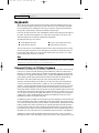
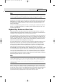
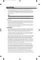
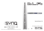
for keyboard layouts, outlines a set of additional keys and key combinations. The 104-key layout
includes left and right Windows keys and an Application key (see Figure 18.1). These keys are used for
operating system and application-level keyboard combinations, similar to the existing Ctrl and Alt
combinations. You don’t need the new keys to use Windows, but software vendors are adding specific
functions to their Windows products that use the new Application key (which provides the same
19 1738 ch18
7/30/04
1018
10:41 AM
Page 1018
Chapter 18
Input Devices
functionality as clicking the right mouse button). The recommended Windows keyboard layout calls
for the Left and Right Windows keys (called WIN keys) to flank the Alt keys on each side of the spacebar, as well as an Application key on the right of the Right Windows key. Note that the exact placement of these keys is up to the keyboard designer, so variations exist from keyboard to keyboard.
F1
Esc
~
`
!
1
Tab Æ
Æ
Caps Lock
F2
@
2
Q
#
3
W
A
F4
$
4
E
S
Z
Shift
F3
%
5
R
D
X
F5
^
6
T
F
C
&
7
Y
G
V
F6
*
8
U
H
B
F7
F9
(
9
I
J
N
F8
)
0
O
K
M
_
P
L
<
,
F10
+
=
{
[
?
/
F12
Print
Scm
SysRo
Scroll
Lock
Pause
Break
¨Backspace
Insert
Home
Page
Up
Num
Lock
/
*
|
\
Delete
End
Page
Down
7
8
9
}
]
"
'
:
;
>
.
F11
Home
4
øEnter
Pg Up
5
¨
Shift
-
6
+
Æ
1
2
3
End
Ø
Pg Dn
Enter
Ctrl
Alt
Alt
Ctrl
¨
Ø
Æ
0
Ins
Del
Application
Left Windows key
Right Windows key
Figure 18.1
The 104-key Windows keyboard layout.
The WIN keys open the Windows Start menu, which you can then navigate with the cursor keys. The
Application key simulates the right mouse button; in most applications, it brings up a context-sensitive
pop-up menu. Several WIN key combinations offer preset macro commands as well. For example, you
can press WIN+E to launch the Windows Explorer application. Table 18.1 shows a list of all the
Windows key combinations used with the 104-key keyboard.
Table 18.1
Windows 9x/Me/2000/XP Key Combinations
Key Combination
Resulting Action
WIN+R
Runs dialog box
WIN+M
Minimize All
Shift+WIN+M
Undo Minimize All
WIN+D
Minimize All or Undo Minimize All
WIN+F1
Help
WIN+E
Starts Windows Explorer
WIN+F
Find Files or Folders
Ctrl+WIN+F
Find Computer
WIN+Tab
Cycles through taskbar buttons
WIN+Break
Displays System Properties dialog box
Application key
Displays a context menu for the selected item
The preceding keystroke combinations work with any manufacturer’s 104-key keyboard, but users of
certain Microsoft 104-key keyboards can enhance their keyboard use further by installing the
IntelliType Pro software supplied by Microsoft with the keyboard.
The Windows keys are not mandatory when running Windows. In fact, preexisting standard key combinations perform the same functions as these newer keys. I also have noticed that only power users
19 1738 ch18
7/30/04
10:41 AM
Page 1019
Keyboards
Chapter 18
1019
wanting to work as efficiently as possible by keeping their hands on the keyboard (and off the mouse)
primarily use these combinations.
The Windows keyboard specification requires that keyboard makers increase the number of trilograms
in their keyboard designs. A trilogram is a combination of three rapidly pressed keys that perform a
special function, such as Ctrl+Alt+Delete. Designing a keyboard so that the switch matrix correctly registers the additional trilograms plus the additional Windows keys adds somewhat to the cost of these
keyboards compared to the previous 101-key standard models.
Virtually all keyboard manufacturers have standardized on 104-key keyboards that include these
Windows-specific keys. Some manufacturers have added browser control or other keys that, although not
standard, can make them easier to use for navigating Web pages and launching various applications.
For additional keyboard combinations you can use, see “Running Windows Without a Mouse” in the
Technical Reference section of the disc included with this book.
USB Keyboards
Most keyboards now on the market can connect to the PC via a USB port instead of the standard PS/2
keyboard port. Because USB is a universal bus that uses a hub to enable multiple devices to connect to
a single port, a single USB port in a system can replace the standard serial and parallel ports as well as
the keyboard and mouse ports. Most current systems and motherboards still include the standard ports
(now called legacy ports) as well as USB, but most so-called legacy-free systems and replacement motherboards have only USB ports for interfacing external devices.
Most keyboard manufacturers now market USB keyboards, but if you want to use your keyboard with
both legacy (PS/2) and legacy-free (USB) systems, the most economic way to do so is to specify a keyboard that includes both a USB connector and an adapter to permit the keyboard to work with PS/2
ports. Although Microsoft’s Natural Keyboard Elite was the first widely available model to offer USB
and PS/2 compatibility, other wired and wireless models from Microsoft, Logitech, Belkin, and others
now offer this feature. You can also purchase third-party USB-to-PS/2 adapters, but these can be expensive and might not work with all keyboards.
Not all systems accept USB keyboards, even those with USB ports, because the standard PC BIOS has a
keyboard driver that expects a standard keyboard port interface to be present. When a USB keyboard is
installed on a system that lacks USB keyboard support, the system can’t use it because no driver exists
in the BIOS to make it work. In fact, some systems see the lack of a standard keyboard as an error and
halt the boot process until one is installed.
To use a keyboard connected via the USB port, you must meet three requirements:
■ Have a USB port in the system
■ Run Microsoft Windows 98, Windows Me, Windows 2000, or Windows XP (all of which include
USB keyboard drivers)
■ Have a system chipset and BIOS that feature USB Legacy support
USB Legacy support means your motherboard has a chipset and ROM BIOS drivers that enable a USB
keyboard to be used outside the Windows GUI environment. When a system has USB Legacy support
enabled, a USB keyboard can be used with MS-DOS (for configuring the system BIOS) when using a
command prompt within Windows or when installing Windows on the system for the first time. If
USB Legacy support is not enabled on the system, a USB keyboard will function only when Windows
is running.
Most recent systems include USB Legacy support, although it might be disabled by default in the system BIOS.
19 1738 ch18
7/30/04
1020
10:41 AM
Chapter 18
Page 1020
Input Devices
Also, if the Windows installation fails and requires manipulation outside of Windows, the USB keyboard
will not function unless it is supported by the chipset and the BIOS. Almost all 1998 and newer systems
with USB ports include a chipset and BIOS with USB Legacy (meaning USB Keyboard) support.
Even though USB Legacy support enables you to use a USB keyboard in almost all situations, don’t
scrap your standard-port keyboards just yet. Some Windows-related bugs and glitches reported by
users include the following:
■ Can’t log on to Windows the first time after installing a USB keyboard. The solution in some cases is
to click Cancel when you are asked to log on and then allow the system to detect the keyboard
and install drivers. The logon should work normally thereafter. In other cases, you might have
to leave the keyboard unplugged when first booting and then plug it in after the OS desktop is
up and running. This allows the keyboard to be detected and drivers loaded.
■ Some USB keyboards won’t work when the Windows Emergency Boot Disk (EBD) is used to start the system. The solution is to turn off the system, connect a standard keyboard, and restart the system.
■ Some users of Windows 98 and Windows 98 SE have reported conflicts between Windows and the BIOS
when USB Legacy support is enabled on some systems. This conflict can result in an incapability to
detect the USB keyboard if you use the Windows 9x shutdown menu and choose to restart the
computer in MS-DOS mode. Check with the system or BIOS vendor for an updated BIOS or a
patch to solve this conflict.
If you have problems with Legacy USB support, look at these possible solutions:
■ Microsoft’s Knowledge Base might address your specific combination of hardware.
■ Your keyboard vendor might offer new drivers.
■ Your system or motherboard vendor might have a BIOS upgrade you can install.
■ Connect the keyboard to the PS/2 port with its adapter (or use a PS/2 keyboard) until you
resolve the problem.
√√
See “Universal Serial Bus,” p. 983.
Notebook Computer Keyboards
One of the biggest influences on keyboard design in recent years has been the proliferation of laptop
and notebook systems. Because of size limitations, it is obviously impossible to use the standard keyboard layout for a portable computer. Manufacturers have come up with many solutions. Unfortunately,
none of these solutions has become an industry standard, as the 101-key layout is. Because of the variations in design, and because a portable system keyboard is not as easily replaceable as that of a desktop
system, the keyboard arrangement should be an important part of your purchasing decision.
Early laptop systems often used smaller-than-normal keys to minimize the size of the keyboard, which
resulted in many complaints from users. Today, the keytops on portable systems are usually comparable in size to that of a desktop keyboard, although some systems include half-sized keytops for the
function keys and other less frequently used keyboard elements. In addition, consumer demand has
caused most manufacturers to retain the inverted-T design for the cursor keys after a few abortive
attempts at changing their arrangement.
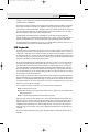
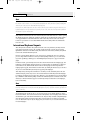
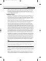
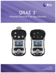
Of course, the most obvious difference in a portable system keyboard is the sacrifice of the numeric
keypad. Most systems now embed the keypad into the standard alphabetical part of the keyboard, as
shown in Figure 18.2. To switch the keys from their standard values to their keypad values, you typically must press a key combination involving a proprietary function key, often labeled Fn.
This is an extremely inconvenient solution, and many users abandon their use of the keypad entirely on
portable systems. Unfortunately, some activities—such as the entry of ASCII codes using the Alt key—
require the use of the keypad numbers, which can be quite frustrating on systems using this arrangement.
19 1738 ch18
7/30/04
10:41 AM
Page 1021
Keyboards
7
8
9
4
5
1
0
1021
*
6
2
Chapter 18
–
+
3
.
/
Figure 18.2 Most portable systems today embed the numeric keypad into an oddly shaped block of keys
on the alphabetical part of the keyboard.
To alleviate this problem, many portable system manufacturers sell external numeric keypads that
plug into the external keyboard port, a serial port, or a USB port. This is a great feature for somebody
performing a lot of numeric data entry.
In addition to keypad control, the Fn key often is used to trigger other proprietary features in portable
systems, such as toggling between an internal and external display and controlling screen brightness
and sound volume.
Some portable system manufacturers have gone to great lengths to provide users with adequate keyboards. For a short time, IBM marketed systems with a keyboard that used a “butterfly” design. The
keyboard was split into two halves that rested on top of one another when the system was closed.
When you opened the lid, the two halves separated to rest side by side, forming a keyboard that was
actually larger than the computer case.
Ironically, the trend toward larger-sized displays in portable systems has made this sort of arrangement unnecessary. Many manufacturers have increased the footprint of their notebook computers to
accommodate 14.1'' and even 15'' display panels, leaving more than adequate room for a keyboard
with full-size keys. However, even on the newest systems, there still isn’t enough room for a separate
numeric keypad.
Num Lock
On IBM systems that support the Enhanced keyboard, when the system detects the keyboard on
powerup, it enables the Num Lock feature and the light goes on. If the system detects an older 84-key
AT-type keyboard, it does not enable the Num Lock function because these keyboards do not have
cursor keys separate from the numeric keypad. When the Enhanced keyboards first appeared in 1986,
many users (including me) were irritated to find that the numeric keypad was automatically enabled
every time the system booted. Most system manufacturers subsequently began integrating a function
into the BIOS setup that enabled you to specify the Num Lock status imposed during the boot
process.
Some users thought that the automatic enabling of Num Lock was a function of the Enhanced keyboard because none of the earlier keyboards seemed to operate in this way. Remember that this function is not really a keyboard function but instead a function of the motherboard ROM BIOS, which
identifies an Enhanced 101-key unit and turns on the Num Lock as a “favor.” In systems with a BIOS
that can’t control the status of the numeric keypad, you can use the DOS 6.0 or higher version
NUMLOCK= parameter in CONFIG.SYS to turn Num Lock on or off, as desired. Some versions of Windows,
particularly Windows NT and Windows 2000 (but not Windows XP), disable Num Lock by default.
19 1738 ch18
7/30/04
1022
10:41 AM
Chapter 18
Page 1022
Input Devices
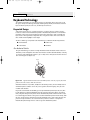
Keyboard Technology
The technology that makes up a typical PC keyboard is very interesting. This section focuses on all
the aspects of keyboard technology and design, including the keyswitches, the interface between the
keyboard and the system, the scan codes, and the keyboard connectors.
Keyswitch Design
Today’s keyboards use any one of several switch types to create the action for each key. Most keyboards use a variation of the mechanical keyswitch. A mechanical keyswitch relies on a mechanical
momentary contact-type switch to make the electrical contact that forms a circuit. Some high-end
keyboards use a more sophisticated design that relies on capacitive switches. This section discusses
these switches and the highlights of each design.
The most common type of keyswitch is the mechanical type, available in the following variations:
■ Pure mechanical
■ Rubber dome
■ Foam element
■ Membrane
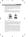
Pure Mechanical Switches
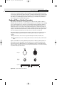
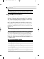
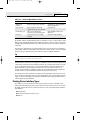
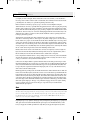
The pure mechanical type is just that—a simple mechanical switch that features metal contacts in a
momentary contact arrangement. The switch often includes a tactile feedback mechanism, consisting
of a clip and spring arrangement designed to give a “clicky” feel to the keyboard and offer some resistance to the keypress (see Figure 18.3).
Keytop
Contacts
Figure 18.3 A typical mechanical switch used in older NMB keyboards. As the key is pressed, the switch
pushes down on the contacts to make the connection.
Mechanical switches are very durable, usually have self-cleaning contacts, and are normally rated for
20 million keystrokes (which is second only to the capacitive switch in longevity). They also offer
excellent tactile feedback.
Despite the tactile feedback and durability provided by mechanical keyswitch keyboards, they have
become much less popular than membrane keyboards (discussed later in this chapter). In addition,
many companies that produce keyboards that use mechanical keyswitches either use them for only a
few of their high-priced models or have phased out their mechanical keyswitch models entirely. With
the price of keyboards nose-diving along with other traditional devices, such as mice and drives, the
pressure on keyboard makers to cut costs has led many of them to abandon or de-emphasize
mechanical-keyswitch designs in favor of the less expensive membrane keyswitch.
19 1738 ch18
7/30/04
10:41 AM
Page 1023
Keyboard Technology
Chapter 18
1023
The Alps Electric mechanical keyswitch is used by many of the vendors who produce mechanical-switch
keyboards, including Alps Electric itself. Other vendors who use mechanical keyswitches for some of
their keyboard models include Adesso, Inc. (www.adesso.com), Avant Prime and Stellar (revivals of the
classic Northgate keyboards and available from Ergonomic Resources; www.ergo-2000.com), Kinesis
(www.kinesis-ergo.com), SIIG (www.siig.com), and Focus (www.focustaipei.com). Many of these vendors
sell through the OEM market, so you must look carefully at the detailed specifications for the keyboard
to see whether it is a mechanical keyswitch model.
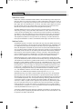
Foam Element Switches
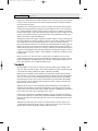
Foam element mechanical switches were a very popular design in some older keyboards. Most of the
older PC keyboards, including models made by Key Tronic and many others, used this technology.
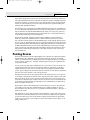
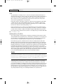
These switches are characterized by a foam element with an electrical contact on the bottom. This
foam element is mounted on the bottom of a plunger that is attached to the key (see Figure 18.4).
Press down
on keytop
Keytop
Return
spring
Flexible
foam
Foil layer on
bottom of foam
Contacts on
circuit board
Figure 18.4
Foil layer makes
connection between
contacts
Typical foam element mechanical keyswitch.
When the switch is pressed, a foil conductor on the bottom of the foam element closes a circuit on
the printed circuit board below. A return spring pushes the key back up when the pressure is released.
The foam dampens the contact, helping to prevent bounce, but unfortunately it gives these keyboards
a “mushy” feel. The big problem with this type of keyswitch design is that little tactile feedback often
exists. These types of keyboards send a clicking sound to the system speaker to signify that contact
has been made. Preferences in keyboard feel are somewhat subjective; I personally do not favor the
foam element switch design.
Another problem with this type of design is that it is more subject to corrosion on the foil conductor
and the circuit board traces below. When this happens, the key strikes can become intermittent,
which can be frustrating. Fortunately, these keyboards are among the easiest to clean. By disassembling the keyboard completely, you usually can remove the circuit board portion—without removing
each foam pad separately—and expose the bottoms of all the pads. Then, you easily can wipe the corrosion and dirt off the bottoms of the foam pads and the circuit board, thus restoring the keyboard to
a “like-new” condition. Unfortunately, over time, the corrosion problem will occur again. I recommend using some Stabilant 22a from D.W. Electrochemicals (www.stabilant.com) to improve the
switch contact action and prevent future corrosion. Because of such problems, the foam element
design is not used much anymore and has been superseded in popularity by the rubber dome design.
KeyTronicEMS, the most well-known user of this technology, now uses a center-bearing membrane
switch technology in its keyboards, so you are likely to encounter foam-switch keyboards only on
very old systems.
19 1738 ch18
7/30/04
1024
10:41 AM
Chapter 18
Page 1024
Input Devices
Rubber Dome Switches
Rubber dome switches are mechanical switches similar to the foam element type but are improved in
many ways. Instead of a spring, these switches use a rubber dome that has a carbon button contact on
the underside. As you press a key, the key plunger presses on the rubber dome, causing it to resist and
then collapse all at once, much like the top of an oil can. As the rubber dome collapses, the user feels
the tactile feedback, and the carbon button makes contact between the circuit board traces below.
When the key is released, the rubber dome re-forms and pushes the key back up.
The rubber eliminates the need for a spring and provides a reasonable amount of tactile feedback
without any special clips or other parts. Rubber dome switches use a carbon button because it resists
corrosion and has a self-cleaning action on the metal contacts below. The rubber domes themselves
are formed into a sheet that completely protects the contacts below from dirt, dust, and even minor
spills. This type of switch design is the simplest, and it uses the fewest parts. This made the rubber
dome keyswitch very reliable for several years. However, its relatively poor tactile feedback has led
most keyboard manufacturers to switch to the membrane switch design covered in the next section.
Membrane Switches
The membrane keyswitch is a variation on the rubber dome type, using a flat, flexible circuit board to
receive input and transmit it to the keyboard microcontroller. Industrial versions of membrane boards
use a single sheet for keys that sits on the rubber dome sheet for protection against harsh environments. This arrangement severely limits key travel. For this reason, flat-surface membrane keyboards
are not considered usable for normal touch typing. However, they are ideal for use in extremely harsh
environments. Because the sheets can be bonded together and sealed from the elements, membrane
keyboards can be used in situations in which no other type could survive. Many industrial applications use membrane keyboards for terminals that do not require extensive data entry but are used
instead to operate equipment, such as cash registers and point-of-sale terminals in restaurants.
Membrane keyswitches are no longer relegated to fast food or industrial uses, though. Over the last
few years, the membrane keyswitch used with conventional keyboard keytops has replaced the rubber
dome keyswitch to become the most popular keyswitch used in low-cost to mid-range keyboards.
Inexpensive to make, membrane switches have become the overwhelming favorite of low-cost Pacific
Rim OEM suppliers and are found in most of the keyboards you’ll see at your local computer store or
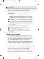
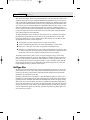
find inside the box of your next complete PC. Although low-end membrane keyswitches have a limited life of only 5–10 million keystrokes, some of the better models are rated to handle up to 20 million keystrokes, putting them in the range of pure mechanical switches for durability (see Figure
18.5). A few membrane switches are even more durable: Cherry Corporation’s G8x-series keyboards
use Cherry’s own 50-million-keystroke membrane switch design (www.cherrycorp.com).
Membrane keyboards provide a firmer touch than rubber dome keyboards or the old foam-element
keyboards, but they are still no match for mechanical or capacitive keyswitch models in their feel.
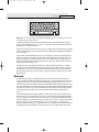
One interesting exception is the line of keyboards made by KeyTronicEMS using its center-bearing version of membrane keyswitches. Most of its keyboards feature Ergo Technology, which has five levels
of force from 35 grams to 80 grams, depending on the relative strength of the fingers used to type
various keys. As little as 35 grams of force is required for keys that are used by the little finger, such as
Q, Z, and A, and greater levels of force are required for keys used by the other fingers. The spacebar
requires the most force: 80 grams. This compares to the standard force level of 55 grams for all keys
on normal keyboards (see Figure 18.6). For more information about keyboards with Ergo Technology,
visit the KeyTronicEMS Web site (www.keytronic.com).
To find the best membrane keyboards from the vast numbers on the market, look at the lifespan rating of the keyswitches. Longer-lasting keyswitches make the keyboard cost more but will lead to a better experience over the life of the keyboard.
19 1738 ch18
7/30/04
10:41 AM
Page 1025
Chapter 18
Keyboard Technology
1025
Keytop
Plunger
Membrane
circuit
board
Silicone
rubber
dome
Figure 18.5
A typical membrane keyswitch used in NMB keyboards.
F1
Esc
~
`
!
1
F2
@
2
Q
Tab
Caps Lock
Shift
Ctrl
F3
#
3
W
A
F4
$
4
E
S
Z
%
5
R
D
X
^
6
&
7
Y
G
V
*
8
U
H
B
F7
F8
(
9
I
J
N
Alt
)
0
O
K
M
F9
_
-
:
;
>
.
45g
F11
+
=
"
'
?
/
55g
Print
Screen
Num
Lock
Caps
Lock
Scroll
Lock
Scroll
Lock
Pause
Home
Page
Up
Num
Lock
/
End
Page
Down
7
Home
8
9
PgUp
4
5
6
Shift
1
End
2
3
PgDn
Ctrl
0
Ins
F12
Backspace
}
]
{
[
P
L
<
,
F10
Alt
35g
Figure 18.6
F6
T
F
C
F5
Insert
Delete
Enter
*
-
+
Enter
65g
•
Del
80g
Force levels used on KeyTronicEMS keyboards with Ergo Technology.
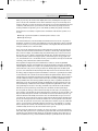
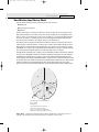
Capacitive Switches
Capacitive switches are the only nonmechanical keyswitch in use today (see Figure 18.7). The capacitive switch is the Cadillac of keyswitches. It is much more expensive than the more common mechanical membrane switch, but it is more resistant to dirt and corrosion and offers the highest-quality tactile
feedback of any type of switch. This type of keyboard is sometimes referred to as a buckling spring keyboard because of the coiled spring used to provide feedback.
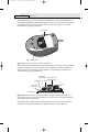
A capacitive switch does not work by making contact between conductors. Instead, two plates usually made
of plastic are connected in a switch matrix designed to detect changes in the capacitance of the circuit.
When the key is pressed, the plunger moves the top plate in relation to the fixed bottom plate.
Typically, a buckling spring mechanism provides for a distinct over-center tactile feedback with a
resounding “click.” As the top plate moves, the capacitance between the two plates changes. The comparator circuitry in the keyboard detects this change.
19 1738 ch18
7/30/04
1026
10:41 AM
Chapter 18
Page 1026
Input Devices
Key
Return
spring
Upper plate
is movable
Lower plate
is fixed
Oscillator
Reference
Figure 18.7
Phase
lock loop
Comparator
Output
A capacitive buckling spring keyswitch.
Because this type of switch does not rely on metal contacts, it is nearly immune to corrosion and dirt.
These switches are also very resistant to the key bounce problems that result in multiple characters
appearing from a single strike. In addition, they are the most durable in the industry—rated for 25
million or more keystrokes, as opposed to 10–20 million for other designs. The tactile feedback is
unsurpassed because the switch provides a relatively loud click and a strong over-center feel. The only
drawback to the design is the cost. Capacitive switch keyboards are among the most expensive
designs. The quality of the feel and their durability make them worth the price, however.
Originally, the only vendor of capacitive keyswitch keyboards was IBM. Although some of IBM’s older
keyboards still feature capacitive keyswitches, most current IBM keyboards use rubber-dome or other
lower-cost keyswitches. In 1991, IBM spun off its keyboard/printer division as Lexmark, which then
spun off the keyboard division as Unicomp in 1996. Today, Unicomp still manufactures and sells
“IBM” keyboards with the classic buckling spring capacitive switch (“clickety” as some would say)
technology. As a bonus, it also has models with the IBM trackpoint built in. You can purchase new
Unicomp (IBM) keyboards direct by calling its toll-free number (800-777-4886) or by visiting its
online store (http://www.pckeyboard.com).
My personal recommendations are for either the EnduraPro/104 (http://www.pckeyboard.com/
ep104.html) or the Customizer 101 or 104 (http://www.pckeyboard.com/customizer.html). These are
brand-new, not reconditioned or rebuilt, keyboards.
The EnduraPro/104 is notable for including a built-in TrackPoint pointing device and a pass-through
mini-DIN mouse port, being programmable and reconfigurable, requiring no special drivers, and of
course having the famous buckling spring keyswitches.
Because of the buckling spring capacitive keyswitches (and the resulting clickety feel), I’ve always
been a huge fan of the IBM, Lexmark, and now Unicomp keyboards. In my opinion, they are the
absolute best keyboards in the world and the only ones I willingly use on desktop systems. I especially
like the fact that they include the IBM TrackPoint because I use a laptop system as my main machine
and therefore use only laptops that include the TrackPoint device (mainly IBM, Toshiba, and some
Dell/HP/others). The feel and durability of the buckling spring capacitive keyswitches is outstanding,
and with the integrated TrackPoint, I never have to move my hands off the keyboard, resulting in
much greater efficiency when working with my systems.
The Keyboard Interface
A keyboard consists of a set of switches mounted in a grid or an array called the key matrix. When a
switch is pressed, a processor in the keyboard identifies which key is pressed by determining which grid
location in the matrix shows continuity. The keyboard processor, which also interprets how long the key
is pressed, can even handle multiple keypresses at the same time. A 16-byte hardware buffer in the keyboard can handle rapid or multiple keypresses, passing each one to the system in succession.
19 1738 ch18
7/30/04
10:41 AM
Page 1027
Keyboard Technology
Chapter 18
1027
When you press a key, the contact bounces slightly in most cases, meaning that several rapid on/off
cycles occur just as the switch makes contact. This is called bounce. The processor in the keyboard is
designed to filter this, or debounce the keystroke. The keyboard processor must distinguish bounce from
a double key strike the keyboard operator intends to make. This is fairly easy, though, because the
bouncing is much more rapid than a person could simulate by striking a key quickly several times.
The keyboard in a PC is actually a computer itself. It communicates with the main system in one of
two ways:
■ Through a special serial data link if a standard keyboard connector is used
■ Through the USB port
The serial data link used by conventional keyboards transmits and receives data in 11-bit packets of
information, consisting of 8 data bits, plus framing and control bits. Although it is indeed a serial link
(in that the data flows on one wire), the keyboard interface is incompatible with the standard RS-232
serial port commonly used to connect modems.
The processor in the original PC keyboard was an Intel 8048 microcontroller chip. Newer keyboards
often use an 8049 version that has built-in ROM or other microcontroller chips compatible with the
8048 or 8049. For example, in its Enhanced keyboards, IBM has always used a custom version of the
Motorola 6805 processor, which is compatible with the Intel chips. The keyboard’s built-in processor
reads the key matrix, debounces the keypress signals, converts the keypress to the appropriate scan
code, and transmits the code to the motherboard. The processors built into the keyboard contain their
own RAM, possibly some ROM, and a built-in serial interface.
In the original PC/XT design, the keyboard serial interface is connected to an 8255 Programmable
Peripheral Interface (PPI) chip on the motherboard of the PC/XT. This chip is connected to the interrupt
controller IRQ1 line, which is used to signal to the system that keyboard data is available. The data is then
sent from the 8255 to the processor via I/O port address 60h. The IRQ1 signal causes the main system
processor to run a subroutine (INT 9h) that interprets the keyboard scan code data and decides what to do.
In an AT-type keyboard design, the keyboard serial interface is connected to a special keyboard controller
on the motherboard. This controller was an Intel 8042 Universal Peripheral Interface (UPI) slave microcontroller chip in the original AT design. This microcontroller is essentially another processor that has its
own 2KB of ROM and 128 bytes of RAM. An 8742 version that uses erasable programmable read-only
memory (EPROM) can be erased and reprogrammed. In the past, when you purchased a motherboard
ROM upgrade for an older system from a motherboard manufacturer, the upgrade included a new keyboard controller chip as well because it had somewhat dependent and updated ROM code in it. Some
older systems might use the 8041 or 8741 chips, which differ only in the amount of built-in ROM or
RAM. However, recent systems incorporate the keyboard controller into the main system chipset.
In an AT system, the (8048-type) microcontroller in the keyboard sends data to the (8042-type) keyboard controller on the motherboard. The motherboard-based controller also can send data back to the
keyboard. When the keyboard controller on the motherboard receives data from the keyboard, it signals the motherboard with an IRQ1 and sends the data to the main motherboard processor via I/O
port address 60h, just as in the PC/XT. Acting as an agent between the keyboard and the main system
processor, the 8042-type keyboard controller can translate scan codes and perform several other functions as well. The system also can send data to the 8042 keyboard controller via port 60h, which then
passes it on to the keyboard. Additionally, when the system needs to send commands to or read the
status of the keyboard controller on the motherboard, it reads or writes through I/O port 64h. These
commands usually are followed by data sent back and forth via port 60h.
In older systems, the 8042 keyboard controller is also used by the system to control the A20 memory
address line, which provides access to system memory greater than 1MB. More modern motherboards
typically incorporate this functionality directly into the motherboard chipset. The AT keyboard connector was renamed the “PS/2” port after the IBM PS/2 family of systems debuted in 1987. That was
19 1738 ch18
7/30/04
1028
10:41 AM
Chapter 18
Page 1028
Input Devices
the time when the connector changed in size from the DIN to the min-DIN, and even though the signals were the same, the mini-DIN version became known from that time forward as the PS/2 port.
Keyboards connected to a USB port work in a surprisingly similar fashion to those connected to conventional DIN or mini-DIN (PS/2) ports after the data reaches the system. Inside the keyboard a variety of custom controller chips is used by various keyboard manufacturers to receive and interpret
keyboard data before sending it to the system via the USB port. Some of these chips contain USB hub
logic to enable the keyboard to act as a USB hub. After the keyboard data reaches the USB port on the
system, the USB port routes the data to the 8042-compatible keyboard controller, where the data is
treated as any other keyboard information.
This process works very well after a system has booted into Windows. But what about users who need
to use the keyboard at a command prompt or within the BIOS configuration routine? As discussed
earlier in this chapter, USB Legacy support must be enabled in the BIOS. A BIOS with USB Legacy support is capable of performing the following tasks:
■ Configure the host controller
■ Enable a USB keyboard and mouse
■ Set up the host controller scheduler
■ Route USB keyboard and mouse input to the 8042 Keyboard Controller
Systems with USB Legacy support enabled use the BIOS to control the USB keyboard until a supported
operating system is loaded. At that point, the USB host controller driver in the operating system takes
control of the keyboard by sending a command called StopBIOS to the BIOS routine that was managing the keyboard. When Windows shuts down to MS-DOS, the USB host controller sends a command
called StartBIOS to restart the BIOS routine that manages the keyboard.
When the BIOS controls the keyboard, after the signals reach the 8042 Keyboard Controller, the USB
keyboard is treated just like a conventional keyboard if the BIOS is correctly designed to work with
USB keyboards. As discussed previously in this chapter, a BIOS upgrade might be necessary in some
cases to provide proper support of USB keyboards on some systems. The system chipset also must support USB Legacy features.
Typematic Functions
If a key on the keyboard is held down, it becomes typematic, which means the keyboard repeatedly
sends the keypress code to the motherboard. In the AT-style keyboards, the typematic rate is adjusted
by sending the appropriate commands to the keyboard processor. This is impossible for the earlier
PC/XT keyboard types because the keyboard interface for these types is not bidirectional.
AT-style keyboards have programmable typematic repeat rate and delay parameters. You can adjust the
typematic repeat rate and delay parameters with settings in your system BIOS (although not all BIOS
chips can control all functions) or in your operating system. In Windows you use the Keyboard icon
in the Control Panel; in DOS you use the MODE command. The next section describes how to adjust
the keyboard parameters in Windows because this is more convenient than the other methods and
enables the user to make further adjustments at any time without restarting the system.
Adjusting Keyboard Parameters in Windows
You can modify the default values for the typematic repeat rate and delay parameters in any version
of Windows using the Keyboard icon in the Control Panel. The Repeat Delay slider controls the number of times a key must be pressed before the character begins to repeat, and the Repeat Rate slider
controls how fast the character repeats after the delay has elapsed.
19 1738 ch18
7/30/04
10:41 AM
Page 1029
Keyboard Technology
Chapter 18
1029
Note
The increments on the Repeat Delay and Repeat Rate sliders in Keyboard Properties in the Control Panel correspond to the
timings given for the MODE command’s RATE and DELAY values. Each mark in the Repeat Delay slider adds about 0.25
seconds to the delay, and the marks in the Repeat Rate slider are worth about one character per second each.
The dialog box also contains a text box you can use to test the settings you have chosen before committing them to your system. When you click in the box and press a key, the keyboard reacts using
the settings currently specified by the sliders, even if you have not yet applied the changes to the
Windows environment.
To learn how to adjust keyboard parameters in DOS, see “Adjusting Keyboard Parameters in DOS” in
Chapter 17 of Upgrading and Repairing PCs, 11th Edition, which is available in electronic form on the
disc included with this book.
Keyboard Key Numbers and Scan Codes
When you press a key on the keyboard, the processor built into the keyboard (8048- or 6805-type)
reads the keyswitch location in the keyboard matrix. The processor then sends to the motherboard a
serial packet of data containing the scan code for the key that was pressed.
This is called the Make code. When the key is released, a corresponding Break code is sent, indicating to
the motherboard that the key has been released. The Break code is equivalent to the Make scan code
plus 80h. For example, if the Make scan code for the “A” key is 1Eh, the Break code would be 9Eh. By
using both Make and Break scan codes, the system can determine whether a particular key has been
held down and determine whether multiple keys are being pressed.
In AT-type motherboards that use an 8042-type keyboard controller, the 8042 chip translates the actual
keyboard scan codes into one of up to three sets of system scan codes, which are sent to the main
processor. It can be useful in some cases to know what these scan codes are, especially when troubleshooting keyboard problems or when reading the keyboard or system scan codes directly in software.
When a keyswitch on the keyboard sticks or otherwise fails, the Make scan code of the failed
keyswitch usually is reported by diagnostics software, including the power on self test (POST), as well
as conventional disk-based diagnostics. This means you must identify the malfunctioning key by its
scan code. See the Technical Reference section of the disc included with this book for a comprehensive listing of keyboard key numbers and scan codes for both the 101/102-key (Enhanced) keyboard
and 104-key Windows keyboard. By looking up the reported scan code on these charts, you can determine which keyswitch is defective or needs to be cleaned.
Note
The 101-key Enhanced keyboards are capable of three scan code sets. Set 1 is the default. Some systems, including
some of the IBM PS/2 machines, use one of the other scan code sets during the POST. For example, my IBM P75 uses
Scan Code Set 2 during the POST but switches to Set 1 during normal operation. This is rare, and it really threw me off
in diagnosing a stuck key problem one time. It is useful to know whether you are having difficulty interpreting the scan
code number, however.
IBM also assigns each key a unique key number to distinguish it from the others. This is important
when you are trying to identify keys on foreign keyboards that might use symbols or characters different from what the U.S. models do. In the Enhanced keyboard, most foreign models are missing one of
the keys (key 29) found on the U.S. version and have two additional keys (keys 42 and 45). This
accounts for the 102-key total instead of the 101 keys found on the U.S. version.
19 1738 ch18
7/30/04
1030
10:41 AM
Chapter 18
Page 1030
Input Devices
Note
See the Technical Reference section of the disc included with this book for a comprehensive listing of keyboard key numbers and scan codes for both the 101/102-key (Enhanced) keyboard and 104-key Windows keyboard, including HID
and hotkey scan codes used on the latest USB and hotkey keyboards.
Knowing these key number figures and scan codes can be useful when you are troubleshooting stuck or failed keys on a
keyboard. Diagnostics can report the defective keyswitch by the scan code, which varies from keyboard to keyboard on
the character it represents and its location.
Many enhanced and USB keyboards now feature hotkeys that either have fixed uses—such as opening
the default Web browser, sending the system into standby mode, and adjusting the speaker volume—
or are programmable for user-defined functions. Each of these keys also has scan codes. USB keyboards use a special series of codes called Human Interface Device (HID), which are translated into
PS/2 scan codes.
International Keyboard Layouts
After the keyboard controller in the system receives the scan codes generated by the keyboard and
passes them to the main processor, the operating system converts the codes into the appropriate
alphanumeric characters. In the United States, these characters are the letters, numbers, and symbols
found on the standard American keyboard.
However, no matter which characters you see on the keytops, adjusting the scan code conversion
process to map different characters to the keys is relatively simple. Windows (post 3.x) takes advantage of this capability by enabling you to install multiple keyboard layouts to support various languages.
In Windows 9x/Me, open the Keyboard icon in the Control Panel and select the Language page. The
Language box should display the keyboard layout you selected when you installed the operating system. In Windows XP, click the Details button found on the Languages tab in the Regional and
Language Options applet (in the Windows Control Panel). By clicking the Add button, you can select
any one of several additional keyboard layouts supporting other languages.
These keyboard layouts map various characters to certain keys on the standard keyboard. The standard French layout provides easy access to the accented characters commonly used in that language.
For example, pressing the 2 key produces the é character. To type the numeral 2, you press the Shift+2
key combination. Other French-speaking countries have different keyboard conventions for the same
characters, so Windows includes support for several keyboard layout variations for some languages,
based on nationality.
Note
It is important to understand that this feature is not the same as installing the operating system in a different language.
These keyboard layouts do not modify the text already displayed onscreen; they only alter the characters generated when
you press certain keys.
The alternative keyboard layouts also do not provide support for non-Roman alphabets, such as
Russian and Chinese. The accented characters and other symbols used in languages such as French
and German are part of the standard ASCII character set. They are always accessible to English-language
users through the Windows Character Map utility or through the use of Alt+keypad combinations. An alternative keyboard layout simply gives you an easier way to access the characters used
in certain languages.
19 1738 ch18
7/30/04
10:41 AM
Page 1031
Chapter 18
Keyboard Technology
1031
If you work on documents using more than one language, you can install as many keyboard layouts
as necessary and switch between them at will. When you click the Enable Indicator on Taskbar check
box on the Language page of the Keyboard control panel, a selector appears in the taskbar’s tray area
that enables you to switch languages easily. On the same page, you can enable a key combination
that switches between the installed keyboard layouts.
Keyboard/Mouse Interface Connectors
Keyboards have a cable with one of two primary types of connectors at the system end. On most
aftermarket keyboards, the cable is connected inside the keyboard case on the keyboard end, requiring
you to open the keyboard case to disconnect or test it; different vendors use different connections,
making cable interchange between brands of keyboards unlikely. When IBM manufactured its own
enhanced keyboards, it used a unique cable assembly that plugged into both the keyboard and the
system unit to make cable replacement or interchange easy. Current IBM keyboards, unfortunately, no
longer use either the shielded data link (SDL) connector inside the keyboard or the telephone cablestyle removable plug-in external keyboard connector used on some more recent models.
Although the method of connecting the keyboard cable to the keyboard can vary, all PC keyboards
(except those using the USB port) use either of the following two connectors to attach to the
computer:
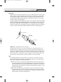
■ 5-pin DIN connector. Used on most PC systems with Baby-AT form factor motherboards
■ 6-pin mini-DIN connector. Used on PS/2 systems and most PCs with LPX, ATX, and NLX motherboards
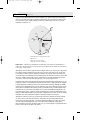
Figure 18.8 and Table 18.2 show the physical layout and pinouts of all the respective keyboard connector plugs and sockets; although the 6-pin SDL connector is not used in this form by most keyboard vendors, most non-IBM keyboards use a somewhat similar connector to attach the keyboard
cable to the inside of the keyboard. You can use the pinouts listed in Table 18.2 to test the continuity
of each wire in the keyboard connector.
Plug
Socket
1
DIN 5-pin
3
4
3
5
1
5
4
2
2
5
Mini-DIN
6-pin
6
3
1
5
6
4
3
4
2
1
2
6-pin SDL
A
Figure 18.8
B
C
D
E
Keyboard and mouse connectors.
F
F
E
D
C
B
A
19 1738 ch18
7/30/04
1032
10:41 AM
Chapter 18
Table 18.2
Page 1032
Input Devices
Keyboard Connector Signals and Specifications
Signal Name
5-Pin DIN
6-Pin Mini-DIN
6-Pin SDL
Test Voltage
Keyboard Data
2
1
B
+4.8V to +5.5V
Ground
4
3
C
—
+5V Power
5
4
E
+2.0V to +5.5V
Keyboard Clock
1
5
D
+2.0V to +5.5V
Not Connected
—
2
A
—
Not Connected
—
6
F
—
Not Connected
3
—
—
—
DIN = Deutsches Institut für Normung e.V., a committee that sets German dimensional standards
SDL = Shielded data link, a type of shielded connector created by AMP and used by IBM and others for keyboard
cables
Motherboard non-USB mouse connectors also use the 6-pin mini-DIN connector and have the same
pinout and signal descriptions as the keyboard connector; however, the data packets are incompatible.
Therefore, you can easily plug a motherboard mouse (PS/2-style) into a mini-DIN keyboard connector
or plug the mini-DIN keyboard connector into a motherboard mouse port. Neither one will work
properly in this situation, though.
Caution
I have also seen PCs with external power supplies that used the same standard DIN connectors to attach the keyboard
and power supply. Although cross-connecting the mini-DIN connectors of a mouse and keyboard is a harmless annoyance, connecting a power supply to a keyboard socket can be disastrous.
USB keyboards use the Series A USB connector to attach to the USB port built into modern computers.
For more information on USB, see Chapter 17, “I/O Interfaces from Serial and Parallel to IEEE 1394
and USB.”
Keyboards with Special Features
Several keyboards on the market have special features not found in standard designs. These additional
features range from simple things, such as built-in calculators, clocks, and volume control, to more
complicated features, such as integrated pointing devices, special character layouts, shapes, and even
programmable keys.
Note
In 1936, August Dvorak patented a simplified character layout called the Dvorak Simplified Keyboard (DSK). The Dvorak
keyboard was designed to replace the common QWERTY layout used on nearly all keyboards available today. The
Dvorak keyboard was approved as an ANSI standard in 1982 but has seen limited use. For a comparison between the
Dvorak keyboard and the common QWERTY keyboard you most likely use, see “The Dvorak Keyboard” in the Technical
Reference section of the disc accompanying this book.
Ergonomic Keyboards
A trend that began in the late 1990s is to change the shape of the keyboard instead of altering the
character layout. This trend has resulted in several so-called ergonomic designs. The goal is to shape
the keyboard to better fit the human hand. The most common of these designs splits the keyboard in
the center, bending the sides outward. Some designs allow the angle between the sides to be adjusted,
19 1738 ch18
7/30/04
10:41 AM
Page 1033
Keyboard Troubleshooting and Repair
Chapter 18
1033
such as the now-discontinued Lexmark Select-Ease, the Goldtouch keyboard designed by Mark
Goldstein (who also designed the Select-Ease), and the Kinesis Maxim split keyboards. Others, such as
the Microsoft Natural keyboard series, PC Concepts Wave, and Cirque Smooth Cat, are fixed. These
split or bent designs more easily conform to the hands’ natural angles while typing than the standard
keyboard. They can improve productivity and typing speed and help prevent repetitive strain injuries
(RSI), such as carpal tunnel syndrome (tendon inflammation). Even more radical keyboard designs are
available from some vendors, including models such as the 3-part Comfort and ErgoMagic keyboards,
the Kinesis concave contoured keyboard, and others. A good source for highly ergonomic keyboards,
pointing devices, and furniture is Ergonomic Resources (www.ergo-2000.com).
Because of their novelty and trendy appeal, some ergonomic keyboards can be considerably more
expensive than traditional designs, but for users with medical problems caused or exacerbated by
improper positioning of the wrists at the keyboard, they can be an important remedy to a serious
problem. General users, however, are highly resistant to change, and these designs have yet to significantly displace the standard keyboard layout. If you don’t want to spend big bucks on the more radical ergonomic keyboards but want to give yourself at least limited protection from RSI, consider
keyboards with a built-in wrist rest or add a gel-based wrist rest to your current keyboard. These provide hand support without making you learn a modified or brand-new keyboard layout.
USB Keyboards with Hubs
Some of the latest USB keyboards feature a built-in USB hub designed to add two or more USB ports
to your system. Even though this sounds like a good idea, keep in mind that a keyboard-based hub
won’t provide additional power to the USB connectors. Powered hubs work better with a wider variety
of devices than unpowered hubs do. I wouldn’t choose a particular model based solely on this feature,
although if your keyboard has it and your devices work well when plugged into it, that’s great. I’d recommend that you use this type of keyboard with your USB mouse or other devices that don’t require
much power. Bus-powered devices such as scanners and Webcams should be connected to a self-powered
hub or directly to the USB ports built in to the computer. USB keyboards and mice correspond to the
USB 1.1 standard but can also be connected to the faster USB 2.0 ports on the latest systems.
Multimedia and Web-Enabled Keyboards
As I discussed earlier in this chapter, many keyboards sold at retail and bundled with systems today
feature fixed-purpose or programmable hotkeys that can launch Web browsers, run the Microsoft
Media Player, adjust the volume on the speakers, change tracks on the CD player, and so forth. You
need Windows 98 or later to use these hotkeys; Windows Me, Windows 2000, and Windows XP add
additional support for these keyboards.
For the best results, you should download the latest drivers for your keyboard and version of
Windows from the keyboard vendor’s Web site.
Keyboard Troubleshooting and Repair
Keyboard errors are usually caused by two simple problems. Other more difficult, intermittent problems can arise, but they are much less common. The most frequent problems are as follows:
■ Defective cables
■ Stuck keys
Defective cables are easy to spot if the failure is not intermittent. If the keyboard stops working altogether or every keystroke results in an error or incorrect character, the cable is likely the culprit.
Troubleshooting is simple, especially if you have a spare cable on hand. Simply replace the suspected
cable with one from a known, working keyboard to verify whether the problem still exists. If it does,
the problem must be elsewhere.
19 1738 ch18
7/30/04
1034
10:41 AM
Chapter 18
Page 1034
Input Devices
If you remove the cable from the keyboard, you can test it for continuity with a digital multimeter
(DMM). DMMs that have an audible continuity tester built in make this procedure much easier to
perform. To test each wire of the cable, insert the DMM’s red pin into the keyboard connector and
touch the DMM’s black pin to the corresponding wire that attaches to the keyboard’s circuit board.
Wiggle the ends of the cable as you check each wire to ensure no intermittent connections exist. If
you discover a problem with the continuity in one of the wires, replace the cable or the entire keyboard, whichever is cheaper. Because replacement keyboards are so inexpensive, it’s almost always
cheaper to replace the entire unit than to get a new cable, unless the keyboard is a deluxe model.
For more information about using digital multimeters for testing hardware, see Chapter 24, “PC
Diagnostics, Testing, and Maintenance.”
Many times you first discover a problem with a keyboard because the system has an error during the
POST. Many systems use error codes in a 3xx numeric format to distinguish the keyboard. If you
encounter any such errors during the POST, write them down. Some BIOS versions do not use cryptic
numeric error codes; they simply state something such as the following:
Keyboard stuck key failure
This message is usually displayed by a system with a Phoenix BIOS if a key is stuck. Unfortunately, the
message does not identify which key it is!
If your system displays a 3xx (keyboard) error preceded by a two-digit hexadecimal number, the number is the scan code of a failing or stuck keyswitch. Look up the scan code in the tables provided in
the Technical Reference section on the disc to determine which keyswitch is the culprit. By removing
the keycap of the offending key and cleaning the switch, you often can solve the problem.
For a simple test of the motherboard keyboard connector, you can check voltages on some of the
pins. Using Figure 18.8, which was shown earlier in the chapter, as a guide, measure the voltages on
various pins of the keyboard connector. To prevent possible damage to the system or keyboard, turn
off the power before disconnecting the keyboard. Then, unplug the keyboard and turn the power
back on. Make measurements between the ground pin and the other pins according to Table 18.2,
shown earlier in the chapter. If the voltages are within these specifications, the motherboard keyboard
circuitry is probably okay.
If your measurements do not match these voltages, the motherboard might be defective. Otherwise,
the keyboard cable or keyboard might be defective. If you suspect that the cable is the problem, the
easiest thing to do is replace the keyboard cable with a known good one. If the system still does not
work normally, you might have to replace the entire keyboard or the motherboard.
In many newer systems, the motherboard’s keyboard and mouse connectors are protected by a fuse
that can be replaced. Look for any type of fuse on the motherboard in the vicinity of the keyboard or
mouse connectors. Other systems might have a socketed keyboard controller chip (8042-type). In that
case, you might be able to repair the motherboard keyboard circuit by replacing this chip. Because
these chips have ROM code in them, you should get the replacement from the motherboard or BIOS
manufacturer. If the motherboard uses a soldered keyboard controller chip or a chipset that integrates
the keyboard controller with other I/O chips, you’ll need to replace the motherboard.
See the disc included with this book for a listing of the standard POST and diagnostic keyboard error
codes used by some systems.
Keyboard Disassembly
Although disassembling a keyboard is possible, most likely you won’t need or want to do that given
the reasonable prices of keyboards. If you do want to disassemble your keyboard, see “Keyboard
Disassembly” in the Technical Reference section of the disc accompanying this book.
19 1738 ch18
7/30/04
10:41 AM
Page 1035
Keyboard Troubleshooting and Repair
Chapter 18
1035
Cleaning a Keyboard
One of the best ways to keep a keyboard in top condition is periodic cleaning. As preventive maintenance, you should vacuum the keyboard weekly, or at least monthly. When vacuuming, you
should use a soft brush attachment; this will help dislodge the dust. Also note that many keyboards
have keycaps that can come off easily. Be careful when vacuuming; otherwise, you’ll have to dig
them out of the vacuum cleaner. I recommend using a small, handheld vacuum cleaner made for
cleaning computers and sewing machines; these have enough suction to get the job done with little
risk of removing your keytops.
You also can use canned compressed air to blow the dust and dirt out instead of using a vacuum.
Before you dust a keyboard with the compressed air, turn the keyboard upside down so that the particles of dirt and dust collected inside can fall out.
On all keyboards, each keycap is removable, which can be handy if a key sticks or acts erratically. For example, a common problem is a key that does not work every time you press it. This
problem usually results from dirt collecting under the key. An excellent tool for removing keycaps on almost any keyboard is the U-shaped chip puller included in many computer tool kits.
Simply slip the hooked ends of the tool under the keycap, squeeze the ends together to grip the
underside of the keycap, and lift up. IBM sells a tool designed specifically for removing keycaps
from its keyboards, but the chip puller works even better. After removing the cap, spray some
compressed air into the space under the cap to dislodge the dirt. Then replace the cap and check
the action of the key.
Caution
When you remove the keycaps, be careful not to remove the spacebar on the original 83-key PC and the 84-key
AT-type keyboards. This bar is difficult to reinstall. The newer 101-key units use a different wire support that can be
removed and replaced much more easily.
When you remove the keycap on some keyboards, you are actually detaching the entire key from
the keyswitch. Be careful during the removal or reassembly of the keyboard; otherwise, you’ll break
the switch. The classic IBM/Lexmark-type keyboards (now made by Unicomp) use a removable keycap that leaves the actual key in place, enabling you to clean under the keycap without the risk of
breaking the switches. If your keyboard doesn’t have removable keycaps, consider using cleaning
wands with soft foam tips to clean beneath the keytops.
Spills can be a problem, too. If you spill a soft drink or cup of coffee into a keyboard, you do not
necessarily have a disaster. Many keyboards that use membrane switches are spill resistant. However,
you should immediately (or as soon as possible) disconnect the keyboard and flush it out with distilled water. Partially disassemble the keyboard and use the water to wash the components. (See
“Keyboard Disassembly” in the Technical Reference section of the disc accompanying this book for
disassembly instructions.) If the spilled liquid has dried, soak the keyboard in some of the water for
a while. When you are sure the keyboard is clean, pour another gallon or so of distilled water over it
and through the keyswitches to wash away any residual dirt. After the unit dries completely, it
should be perfectly functional. You might be surprised to know that drenching your keyboard with
water does not harm the components. Just make sure you use distilled water, which is free from
residue or mineral content (bottled water is not distilled; the distinct taste of many bottled waters
comes from the trace minerals they contain!). Also, make sure the keyboard is fully dry before you
try to use it; otherwise, some of the components might short out.
19 1738 ch18
7/30/04
1036
10:41 AM
Chapter 18
Page 1036
Input Devices
Tip
If spills or excessive dust or dirt are expected because of the environment or conditions in which the PC is used, several
companies make thin membrane skins that mold over the top of the keyboard, protecting it from liquids, dust, and other contaminants. These skins are generally thin enough so that they don’t interfere too much with the typing or action of the keys.
Keyboard Recommendations
In most cases, replacing a keyboard is cheaper or more cost effective than repairing it. This is especially true if the keyboard has an internal malfunction or if one of the keyswitches is defective.
Replacement parts for keyboards are almost impossible to procure, and installing any repair part is
usually difficult. In addition, many of the keyboards supplied with lower-cost PCs leave much to be
desired. They often have a mushy feel, with little or no tactile feedback. A poor keyboard can make
using a system a frustrating experience, especially if you are a touch typist. For all these reasons, it is
often a good idea to replace an existing keyboard with something better.
Perhaps the highest-quality keyboards in the entire computer industry are those made by IBM, or,
more accurately today, Unicomp. Unicomp maintains an extensive selection of more than 1,400
Lexmark and IBM keyboard models and continues to develop and sell a wide variety of traditional
and customized models, including keyboards that match the school colors of several universities.
Unicomp sells keyboards directly via its Web site at www.pckeyboard.com. My personal favorite is the
black EnduraPro 104.
Note
See the section “Replacement Keyboards” in Chapter 17 of Upgrading and Repairing PCs, 11th Edition on this book’s
disc for a listing of IBM keyboard and cable part numbers.
Some of the classic-design IBM keyboards are available in the retail market under either the IBM or
IBM Options brand name. Items under the IBM Options program are sold direct by IBM’s Web site
(www.pc.ibm.com) or through normal retail channels, such as CompUSA and Computer Discount
Warehouse (CDW). These items are also priced much more cheaply than items purchased as spare
parts. They include a full warranty and are sold as complete packages, including cables. Table 18.3
lists some of the IBM Options keyboards and part numbers; even though the IBM Web site no longer
offers these models, they can be purchased from various online retailers. Models marked with an * are
also available from Unicomp.
Table 18.3
IBM Options Keyboards (Sold Retail)
Description
Part Number
IBM Enhanced keyboard (cable w/DIN plug)
92G7454*
IBM Enhanced keyboard (cable w/mini-DIN plug)
92G7453*
IBM Enhanced keyboard, built-in Trackball (cable w/DIN plug)
92G7456*
IBM Enhanced keyboard, built-in Trackball (cable w/mini-DIN plug)
92G7455*
IBM Enhanced keyboard, integrated TrackPoint II (cables w/mini-DIN plugs)
92G7461*
IBM TrackPoint IV keyboard, Black
01K1260
IBM TrackPoint IV keyboard, White
01K1259
IBM TrackPoint USB Space Saver keyboard (black)
22P5150
IBM USB Keyboard with two-port hub (black)
10K3849
IBM Rapid Access III (black)
22P5185
19 1738 ch18
7/30/04
10:41 AM
Page 1037
Pointing Devices
Chapter 18
1037
Keep in mind, though, that because IBM spun off its keyboard business some years ago, many recent
and current IBM-labeled keyboards no longer have the distinct feel, quality, or durability found in the
older models. Ironically, one of the best ways to get an “IBM” keyboard is to buy the model with the
features you want from Unicomp, most of whose keyboards still use the capacitive buckling spring
technology IBM originally made famous.
The extremely positive tactile feedback of the IBM/Lexmark/Unicomp design is also a benchmark for
the rest of the industry. Although keyboard feel is an issue of personal preference, I have never used a
keyboard that feels better than the IBM/Lexmark/Unicomp designs. I now equip every system I use
with a Unicomp keyboard, including the many non-IBM systems I use. You can purchase these keyboards directly from Unicomp at very reasonable prices.
Many models are available, including some with a built-in trackball or even the revolutionary
TrackPoint pointing device. (TrackPoint refers to a small stick mounted between the G, H, and B
keys.) This device was first featured on the IBM ThinkPad laptop systems, although the keyboards are
now sold for use on other manufacturers’ PCs. The technology is being licensed to many other manufacturers, including Toshiba. Other manufacturers of high-quality keyboards that are similar in feel to
the IBM/Lexmark/Unicomp units are Alps, Lite-On, NMB Technologies, and the revived Northgate
designs sold under the Avant Prime and Avant Stellar names by Creative Vision Technologies. These
keyboards have excellent tactile feedback, with a positive click sound. They are my second choice,
after a Unicomp unit.
Pointing Devices
The mouse was invented in 1964 by Douglas Englebart, who at the time was working at the Stanford
Research Institute (SRI), a think tank sponsored by Stanford University. The mouse was officially
called an X-Y Position Indicator for a Display System. Xerox later applied the mouse to its revolutionary Alto computer system in 1973. At the time, unfortunately, these systems were experimental and
used purely for research.
In 1979, several people from Apple—including Steve Jobs—were invited to see the Alto and the software that ran the system. Steve Jobs was blown away by what he saw as the future of computing,
which included the use of the mouse as a pointing device and the graphical user interface (GUI) it
operated. Apple promptly incorporated these features into what was to become the Lisa computer and
lured away 15–20 Xerox scientists to work on the Apple system.
Although Xerox released the Star 8010 computer that used this technology in 1981, it was expensive,
poorly marketed, and perhaps way ahead of its time. Apple released the Lisa computer, its first system
that used the mouse, in 1983. It was not a runaway success, largely because of its $10,000 list price,
but by then Jobs already had Apple working on the low-cost successor to the Lisa: the Macintosh. The
Apple Macintosh was introduced in 1984. Although it was not an immediate hit, the Macintosh has
grown in popularity since that time.
Many credit the Macintosh with inventing the mouse and GUI, but as you can see, this technology
was actually borrowed from others, including SRI and Xerox. Certainly the Macintosh, and now
Microsoft Windows and OS/2, have gone on to popularize this interface and bring it to the legion of
Intel-based PC systems.
Although the mouse did not catch on quickly in the PC marketplace, today the GUIs for PC systems,
such as Windows, practically demand the use of a mouse. Therefore, virtually every new system sold
at retail comes with a mouse. And, because the mice packaged with retail systems are seldom highquality or up-to-date designs, sooner or later most users are in the market for a better mouse or compatible pointing device.
19 1738 ch18
7/30/04
1038
10:41 AM
Chapter 18
Page 1038
Input Devices
Mice come in many shapes and sizes from many manufacturers. Some have taken the standard mouse
design and turned it upside down, creating the trackball. In the trackball devices, you move the ball
with your hand directly rather than moving the unit itself. Trackballs were originally found on arcade
video games, such as Missile Command, but have become popular with users who have limited desk
space. In most cases, the dedicated trackballs have a much larger ball than would be found on a standard mouse. Other than the orientation and perhaps the size of the ball, a trackball is identical to a
mouse in design, basic function, and electrical interface. Like many recent mice, trackballs often come
in ergonomic designs, and the more recent models even use the same optical tracking mechanisms
used by the latest Microsoft and Logitech mice.
The largest manufacturers of mice are Microsoft and Logitech; these two companies provide designs
that inspire the rest of the industry and each other and are popular OEM choices as well as retail
brands. Even though mice can come in different varieties, their actual use and care differ very little.
The standard mouse consists of several components:
■ A housing that you hold in your hand and move around on your desktop
■ A method of transmitting movement to the system: either ball/roller or optical sensors
■ Buttons (two or more, and often a wheel or toggle switch) for making selections
■ An interface for connecting the mouse to the system; conventional mice use a wire and connector, whereas wireless mice use a radio-frequency or infrared transceiver in both the mouse and a
separate unit connected to the computer to interface the mouse to the computer
The housing, which is made of plastic, consists of very few moving parts. On top of the housing,
where your fingers normally rest, are buttons. There might be any number of buttons, but in the PC
world, two is the standard. If your mouse has additional buttons or a wheel, specialized driver software provided by the mouse vendor is required for them to operate to their full potential. Although
the latest versions of Windows support scrolling mice, other features supported by the vendor still
require installing the vendor’s own mouse driver software.
Ball-Type Mice
The bottom of the mouse housing is where the detection mechanisms or electronics are located. On
traditional mice, the bottom of the housing contains a small, rubber ball that rolls as you move the
mouse across the tabletop. The movements of this rubber ball are translated into electrical signals
transmitted to the computer across the cable.
Internally, a ball-driven mouse is very simple, too. The ball usually rests against two rollers: one for
translating the x-axis movement and the other for translating the y-axis movement. These rollers are
typically connected to small disks with shutters that alternately block and allow the passage of light.
Small optical sensors detect movement of the wheels by watching an internal infrared light blink on
and off as the shutter wheel rotates and “chops” the light. These blinks are translated into movement
along the axes. This type of setup, called an opto-mechanical mechanism, is still the most popular type
of mouse mechanism (see Figure 18.9), although optical mice are gaining in popularity. Figure 18.10
shows a PS/2 mouse connector.
19 1738 ch18
7/30/04
10:41 AM
Page 1039
Pointing Devices
Figure 18.9
1039
Typical opto-mechanical mouse mechanism.
5
6
4
3
1
Figure 18.10
Chapter 18
2
Typical PS/2-type mouse connector.
Optical Mice
The other major method of motion detection is optical. Some of the early mice made by Mouse
Systems and a few other vendors used a sensor that required a special grid-marked pad. Although
these mice were very accurate, the need to use them with a pad caused them to fall out of favor.
Microsoft’s IntelliMouse Explorer pioneered the return of optical mice. The IntelliMouse Explorer and
the other new-style optical mice from Logitech and other vendors use optical technology to detect
movement, and they have no moving parts of their own (except for the scroll wheel and buttons on
top). Today’s optical mice need no pad; they can work on virtually any surface. This is done by
upgrading the optical sensor from the simple type used in older optical mice to a more advanced CCD
(charge coupled device). This essentially is a crude version of a video camera sensor that detects movement by seeing the surface move under the mouse. An LED is used to provide light for the sensor.
19 1738 ch18
7/30/04
1040
10:41 AM
Chapter 18
Page 1040
Input Devices
The IntelliMouse Explorer revolutionized the mouse industry; first Logitech, then virtually all other
mouse makers, including both retail and OEM suppliers, have moved to optical mice for most of their
product lines, offering a wide variety of optical mice in most price ranges. Figure 18.11 shows the
essential features of a typical optical mouse.
CCD camera
LED to illuminate surface
Figure 18.11
The bottom of the Logitech iFeel optical mouse.
Their versatility and low maintenance (not to mention that neat red or blue glow out the sides!) make
optical mice an attractive choice, and the variety of models available from both vendors means you
can have the latest optical technology for about the price of a good ball-type mouse. Figure 18.12
shows the interior of a typical optical mouse.
Printed circuit
board (PCB)
Lens/light pipe
Base plate
(bottom of mouse)
Clip holding sensor/
LED subassembly
Sensor
LED
Mousing surface
Figure 18.12 The LED inside an optical mouse illuminates the surface by blinking many times per second. The light is reflected from the mousing surface back to the sensor, which converts the information into
digital form and sends it to the computer.
All optical mice have a resolution of at least 400dpi and at least one sensor. However, for better performance, some optical mice have improved on these basic features, as listed in Table 18.4.
19 1738 ch18
7/30/04
10:41 AM
Page 1041
Pointing Devices
Table 18.4
Chapter 18
1041
Enhanced Optical Mouse Features
Feature
Benefit
Sample Product
800dpi optical
resolution
Improves accuracy for mouse positioning
Logitech MX series, Microsoft IntelliMouse
Explorer and Optical series
Larger sensor size
Improves tracking on surfaces with
repetitive patterns, such as wood desktops
Logitech MX series
Faster tracking speed
Able to keep up with fast hand
movements, such as when playing games
Microsoft IntelliMouse Explorer and
Optical series
Dual sensors
Faster speed and accuracy, especially
for gaming
Logitech MouseMan Dual Optical
Optical mice, similar to traditional ball-type mice, are available as corded or cordless models. Cordless
ball-type mice are usually much larger than ordinary mice because of the need to find room for both
the bulky ball mechanism and batteries, but cordless optical mice are about the same size as high-end
corded mice.
The cable can be any length, but it is typically between 4 and 6 feet long. Mice are also available in a
cordless design, which uses either infrared or RF transceivers to replace the cable. A receiver is plugged
into the mouse port, while the battery-powered mouse contains a compatible transmitter.
Tip
If you have a choice on the length of cable to buy, get a longer one. This allows easier placement of the mouse in relation to your computer. Extension cables can be used if necessary.
After the mouse is connected to your computer, it communicates with your system through the use of
a device driver, which can be loaded explicitly or built into the operating system software. For example, no separate drivers are necessary to use a mouse with Windows or OS/2, but using the mouse
with most DOS-based programs requires a separate driver to be loaded from the CONFIG.SYS or
AUTOEXEC.BAT file. Regardless of whether it is built in, the driver translates the electrical signals sent
from the mouse into positional information and indicates the status of the buttons.
The standard mouse drivers in Windows are designed for the traditional two-button mouse or scroll
mouse (in Windows Me/2000/XP or later), but increasing numbers of mice feature additional buttons,
toggles, or wheels to make them more useful. These additional features require special mouse driver
software supplied by the manufacturer.
Pointing Device Interface Types
The connector used to attach your mouse to the system depends on the type of interface you are
using. Three main interfaces are used for mouse connections, with a fourth option you also occasionally might encounter. Mice are most commonly connected to your computer through the following
three interfaces:
■ Serial interface
■ Dedicated motherboard (PS/2) mouse port
■ USB port
19 1738 ch18
7/30/04
1042
10:41 AM
Chapter 18
Page 1042
Input Devices
Serial
A popular method of connecting a mouse to older PCs is through the standard serial interface. As
with other serial devices, the connector on the end of the mouse cable is typically a 9-pin female connector; some very old mice used a 25-pin female connector. Only a couple of pins in the DB-9 or
DB-25 connector are used for communications between the mouse and the device driver, but the
mouse connector typically has all 9 or 25 pins present.
Because most older PCs come with two serial ports, a serial mouse can be plugged into either COM1
or COM2. The device driver, when initializing, searches the ports to determine to which one the
mouse is connected. Some mouse drivers can’t function if the serial port is set to COM3 or COM4,
but most newer drivers can work with any COM port 1–4.
Because a serial mouse does not connect to the system directly, it does not use system resources by
itself. Instead, the resources are those used by the serial port to which it is connected. For example, if
you have a mouse connected to COM2, and if COM2 is using the default IRQ and I/O port address
range, both the serial port and the mouse connected to it use IRQ3 and I/O port addresses 2F8h–2FFh.
√√
See “Serial Ports,” p. 997.
Motherboard Mouse Port (PS/2)
Most computers include a dedicated mouse port built into the motherboard. This practice was introduced by IBM with the PS/2 systems in 1987, so this interface is often referred to as a PS/2 mouse interface. This term does not imply that such a mouse can work only with a PS/2; instead, it means the
mouse can connect to any system that has a dedicated mouse port on the motherboard.
From a hardware perspective, a motherboard mouse connector is usually exactly the same as the
mini-DIN connector used for newer keyboards. In fact, the motherboard mouse port is connected to
the 8042-type keyboard controller found on the motherboard. All the PS/2 computers include miniDIN keyboard and mouse port connectors on the back. Most computers based on the semiproprietary
LPX motherboards and all ATX-series motherboards use these same connectors for space reasons.
Most Baby-AT motherboards have a pin-header type connector for the mouse port because most standard cases do not have a provision for the mini-DIN mouse connector. If that is the case, an adapter
cable is usually supplied with the system. This cable adapts the pin-header connector on the motherboard to the standard mini-DIN type connector used for the motherboard mouse.
Caution
As mentioned in the “Keyboard/Mouse Interface Connectors” section earlier in this chapter, the mini-DIN sockets used for
both keyboard and mouse connections on many systems are physically and electrically interchangeable, but the data packets
they carry are not. Be sure to plug each device into the correct socket; otherwise, neither will function correctly. Don’t panic if
you mix them up, though. They are electrically identical to each other, so you can’t damage the ports or the devices.
Connecting a mouse to the built-in mouse port is the best method of connection on systems that
don’t have USB ports because you do not sacrifice any of the system’s interface slots or any serial
ports, and the performance is not limited by the serial port circuitry. The standard resource usage for a
motherboard (or PS/2) mouse port is IRQ12, as well as I/O port addresses 60h and 64h. Because the
motherboard mouse port uses the 8042-type keyboard controller chip, the port addresses are those of
this chip. IRQ12 is an interrupt that is usually free on most systems, but if you use a USB mouse, you
can probably disable the mouse port to make IRQ12 available for use by another device.
19 1738 ch18
7/30/04
10:41 AM
Page 1043
Pointing Devices
Chapter 18
1043
Hybrid Mice
Hybrid mice are those designed to plug into two types of ports. Although a few low-cost mice sold at
retail are designed to plug into either the serial port or the PS/2 port, most mice on the retail market
today are designed to plug into either the PS/2 port or the USB port. These combination mice are
more flexible than the mice typically bundled with systems, which are designed to work only with
the PS/2 or USB port to which they attach.
Circuitry in a hybrid mouse automatically detects the type of port to which it is connected and configures
the mouse automatically. Serial-PS/2 hybrid mice usually come with a mini-DIN connector on the end of
their cable and an adapter that converts the mini-DIN to a 9- or 25-pin serial port connector, although
the reverse is sometimes true on early examples of these mice. PS/2-USB mice usually come with the USB
connector on the end of their cable and include a mini-DIN (PS/2) adapter, as shown in Figure 18.13.
PS/2 mouse port
PS/2-USB
mouse adapter
USB mouse
Figure 18.13
A typical USB mouse with a PS/2 adapter.
Sometimes people use adapters to try to connect a serial mouse to a motherboard mouse port or a
motherboard mouse to a serial port. If this does not work, it is not the fault of the adapter. If the
mouse does not explicitly state that it is both a serial and a PS/2-type mouse, it works only on the single interface for which it was designed. Most of the time, you find the designation for which type of
mouse you have printed on its underside. A safe rule of thumb to follow is if the mouse didn’t come
with an adapter or come bundled with a system, it probably won’t work with an adapter.
USB
The extremely flexible USB port has become the most popular port to use for mice as well as keyboards and other I/O devices. Compared to the other interfaces, USB mice (and other USB pointing
devices such as trackballs) have the following advantages:
■ USB mice move much more smoothly than the traditional PS/2-type. This is because the frequency
with which the mouse reports its position is much higher. A typical PS/2 mouse has a reporting
rate of about 40Hz, whereas an average USB-wired mouse has a reporting rate of 125Hz (most
USB wireless mice have a reporting rate of 40Hz–50Hz). Several utilities are available to test and
adjust the mouse frequency.
■ Mice with the most advanced features are usually made especially for the USB port. One example is
the Logitech iFeel mouse, the first mouse with an optical sensor plus force feedback. It vibrates
gently as you move the mouse over clickable buttons on Web pages, software menus, and the
Windows desktop, and it’s made especially for USB.
19 1738 ch18
7/30/04
1044
10:41 AM
Chapter 18
Page 1044
Input Devices
■ USB mice and pointing devices, similar to all other USB devices, are hot-swappable. If you like to use a
trackball and your computing partners prefer mice, you can just lean over and unplug the other
users’ pointing device and plug in your own, or move it from PC to PC. You can’t do that with
the other port types.
■ USB mice can be attached to a USB hub, such as the hubs contained in some USB keyboards, as well as
standalone hubs. Using a hub makes attaching and removing your mouse easy without crawling
around on the floor to reach the back of the computer. Many computers now have front-mounted
USB ports, letting you easily attach and remove a USB mouse without the use of an external hub.
Although the early USB mice were decidedly on the premium end of the price scale, low-cost USB
mice are now available for less than $20.
If you want to use a USB mouse at an MS-DOS prompt, in Windows safe mode, or in some other environment outside of normal Windows 98 or later, make sure that USB Legacy mode is enabled in your
PC’s BIOS, as discussed earlier in this chapter. Legacy mode enables non-USB-aware systems to recognize a USB keyboard and mouse.
A fourth type of connection, the bus mouse (referred to by Microsoft as the Inport mouse), used a dedicated adapter card and is now obsolete. For more information about the bus mouse, see Chapter 17 of
Upgrading and Repairing PCs, 11th Edition, which is included on the disc supplied with this book.
Mouse Troubleshooting
If you are experiencing problems with your mouse, you need to look in only two general places—
hardware or software. Because mice are basically simple devices, looking at the hardware takes very
little time. Detecting and correcting software problems can take a bit longer, however. To troubleshoot
wireless mice, see “Troubleshooting Wireless Input Devices,” later in this chapter.
Cleaning Your Mouse
If you notice that the mouse pointer moves across the screen in a jerky fashion, it might be time to
clean your mouse. For a mouse with a roller-ball, this jerkiness is caused when dirt and dust become
trapped around the mouse’s ball-and-roller assembly, thereby restricting its free movement.
From a hardware perspective, the mouse is a simple device, so cleaning it is easy. The first step is to
turn the mouse housing over so that you can see the ball on the bottom. Notice that surrounding the
ball is an access panel you can open. Sometimes instructions indicate how the panel is to be opened.
(Some off-brand mice might require you to remove some screws to get at the roller ball.) Remove the
panel to see more of the roller ball and the socket in which it rests.
If you turn the mouse back over, the rubber roller ball should fall into your hand. Take a look at the ball.
It might be gray or black, but it should have no visible dirt or other contamination. If it does, wash it in
soapy water or a mild solvent, such as contact lens cleaner solution or alcohol, and dry it off.
Now take a look at the socket in which the roller ball normally rests. You will see two or three small
wheels or bars against which the ball usually rolls. If you see dust or dirt on or around these wheels or
bars, you need to clean them. The best way is to use a compressed air duster, which can blow out any dust
or dirt. You also can use some electrical contact cleaner to clean the rollers. Remember, any remaining dirt
or dust impedes the movement of the roller ball and results in the mouse not working as it should.
Put the mouse back together by inserting the roller ball into the socket and then securely attaching
the cover panel. The mouse should look just as it did before you removed the panel, except that it
will be noticeably cleaner.
One of the major advantages of the new breed of optical mice is the lack of moving parts. Just wipe
away dust from the optical sensor, and that’s all the cleaning an optical mouse needs.
19 1738 ch18
7/30/04
10:41 AM
Page 1045
Pointing Devices
Chapter 18
1045
Interrupt Conflicts
Interrupts are internal signals used by your computer to indicate when something needs to happen.
With a mouse, an interrupt is used whenever the mouse has information to send to the mouse driver.
If a conflict occurs and the same interrupt used by the mouse is used by a different device, the mouse
will not work properly—if at all.
Interrupt conflicts caused by mice can occur when a serial or PS/2 mouse is used, but not when a USB
mouse is used. Mouse ports built in to modern motherboards are almost always set to IRQ12. If your
system has a motherboard mouse port, be sure you don’t set any other adapter cards to IRQ12; otherwise, a conflict will result.
If you are using a serial mouse, interrupt conflicts typically occur if you add third and fourth serial
ports, using either an expansion card or internal serial device, such as a modem. This happens
because in ISA bus systems, the odd-numbered serial ports (1 and 3) usually are configured to use the
same interrupts as the even-numbered ports (2 and 4) are; IRQ4 is shared by default between COM1
and COM3, and IRQ 2 is shared by default between COM2 and COM4. Therefore, if your mouse is
connected to COM2 and an internal modem uses COM4, they both might use the same interrupt,
and you can’t use them at the same time.
Because the mouse generates interrupts only when it is moved, you might find that the modem functions properly until you touch the mouse, at which point the modem is disconnected. Another example
is when your system will run properly until you try to go online with your modem; then the conflict
usually locks up the system. You might be able to use the mouse and modem at the same time by moving one of them to a different serial port. For instance, if your mouse uses COM1 and the modem still
uses COM4, you can use them both simultaneously because odd and even ports use different interrupts.
The best way around these interrupt conflicts is to make sure no two devices use the same interrupt.
Serial port adapters are available for adding COM3 and COM4 serial ports that do not share the interrupts used by COM1 and COM2. These boards enable the new COM ports to use other normally
available interrupts, such as IRQs 10, 11, 12, 15, and 5. I never recommend configuring a system with
shared ISA interrupts; it is a sure way to run into problems later. However, interrupts used by PCI
boards can be shared if you use Windows 95 OSR 2.x, Windows 98, Windows Me, Windows 2000, or
Windows XP with recent chipsets that support a feature called IRQ steering.
√√
See “PCI Interrupts,” p. 370.
If you suspect an interrupt problem with a bus-type mouse, you can use the Device Manager built
into Windows (which is accessible from the System control panel).
◊◊
See “Operating System Diagnostics,” p. 1299.
The Device Manager in Windows 9x/Me/2000/XP is part of the Plug-and-Play (PnP) software for the
system, and it is usually 100% accurate on PnP hardware. Although some of these interrupt-reporting
programs can have problems, most can easily identify the mouse IRQ if the mouse driver has been
loaded. After the IRQ is identified, you might need to change the IRQ setting of the bus mouse
adapter or one or more other devices in your system so that everything works together properly.
If your driver refuses to recognize the mouse at all, regardless of its type, try using a different mouse
that you know works. Replacing a defective mouse with a known good one might be the only way to
know whether the problem is indeed caused by a bad mouse.
I have had problems in which a bad mouse caused the system to lock right as the driver loaded or
when third-party diagnostics were being run on the system. If you use a DOS-based diagnostic, such
as Microsoft MSD or AMIDIAG, and the system locks up during the mouse test, you have found a
problem with either the mouse or the mouse port. Try replacing the mouse to see whether that helps.
If it does not, you might need to replace the serial port or bus mouse adapter. If a motherboard-based
19 1738 ch18
7/30/04
1046
10:41 AM
Chapter 18
Page 1046
Input Devices
mouse port goes bad, you can replace the entire motherboard—which is usually expensive—or you
can just disable the motherboard mouse port via jumpers or the system BIOS setup program and
install a serial mouse instead. This method enables you to continue using the system without having
to replace the motherboard. On systems with Windows 98/Me/2000/XP, you also can switch to a USB
mouse, using USB ports on your motherboard or by installing a PCI-based USB card—provided your
system has a USB port.
Note
To learn more about using the Microsoft MSD diagnostic program to test for mouse or mouse-port problems, see Chapters 17
and 25 of Upgrading and Repairing PCs, 11th Edition, which is included on the disc packaged with this book.
Driver Software
Most mice and other pointing devices in use today emulate a Microsoft mouse, enabling you to have
basic two-button plus scrolling functions with current versions of Windows without loading any special drivers. However, if your mouse has additional buttons or other special features, you will need to
install device-specific drivers available from the mouse vendor.
If you plan to use the mouse from a Windows 9x/Me command prompt or with DOS, you must load
the driver manually. To learn more about this process, see “Mouse Driver Software” in the Technical
Reference section of the disc packaged with this book.
Scroll Wheels
Late in 1996, Microsoft introduced the IntelliMouse, which differed from standard Microsoft mice by
adding a small gray wheel between the mouse buttons. This was the first scrolling mouse, and since
then, Logitech, IBM, and virtually all other mouse vendors have made scroll wheels or similar devices
standard across almost all models, including OEM mice bundled with computer systems.
The wheel has two main functions. The primary function is to act as a scrolling device, enabling you
to scroll through documents or Web pages by manipulating the wheel with your index finger. The
wheel also functions as a third mouse button when you press it.
Although three-button mice have been available for years from vendors such as Logitech, the scrolling
function provided a real breakthrough. No longer do you have to move the mouse pointer to click the
scrollbar on the right side of your screen or take your hand off the mouse to use the arrow keys on
the keyboard. You just push or pull on the wheel. This is a major convenience, especially when
browsing Web pages or working with word processing documents or spreadsheets. Also, unlike threebutton mice from other vendors, the IntelliMouse’s wheel-button doesn’t seem to get in the way and
you are less likely to click it by mistake. Although it took a while for software vendors to support the
wheel, improvements in application software and Windows support allow today’s wheel mice to be
fully useful with almost any recent or current Windows program.
Each vendor’s mouse driver software offers unique features to enhance the basic operation of the
mouse. For example, Logitech’s MouseWare 9.7 driver enables you to select many uses for all three
mouse buttons (the scroll wheel is treated as a third mouse button), as well as provides various options
for how to scroll with each wheel click (three lines, six lines, or one screen). Microsoft’s IntelliMouse
driver offers a feature called ClickLock, which allows you to drag items without holding down the primary mouse button. In addition, it offers a Universal Scroll feature that adds scrolling mouse support
to applications that lack such support. To get the most from whatever scrolling or other advancedfeature mouse you have, be sure you periodically download and install new mouse drivers.
Instead of the wheel used by Microsoft and Logitech, IBM and other mouse vendors frequently use
various types of buttons for scrolling. Some inexpensive mice use a rocker switch, but the most elegant of the non-wheel alternatives is IBM’s ScrollPoint Pro, which uses a pressure-sensitive scroll stick
19 1738 ch18
7/30/04
10:41 AM
Page 1047
Pointing Devices
Chapter 18
1047
similar to the TrackPoint pointing device used on IBM’s notebook computer and some PC keyboards
made by IBM and Unicomp. The scrollpointer in the center of the mouse enables you to smoothly
scroll through documents without having to lift your finger to roll the wheel, as you do on the
Microsoft version, which makes it much easier and more convenient to use. Because no moving parts
exist, the ScrollPoint is also more reliable.
TrackPoint II/III/IV
On October 20, 1992, IBM introduced a revolutionary new pointing device called TrackPoint II as an
integrated feature of its new ThinkPad 700 and 700C computers. Often referred to as a pointing stick
device, TrackPoint II and its successors consist primarily of a small rubber cap that appears on the keyboard right above the B key, between the G and H keys. This was the first significant new pointing
device since the mouse had been invented nearly 30 years earlier!
This device occupies no space on a desk, does not have to be adjusted for left-handed or right-handed
use, has no moving parts to fail or become dirty, and (most importantly) does not require you to
move your hands from the home row to use it. This is an absolute boon for touch typists.
I was fortunate enough to meet the actual creator and designer of this device in early 1992 at the
spring Comdex/Windows World in Chicago. He was in a small corner of the IBM booth showing off
his custom-made keyboards with a small silicone rubber nub in the middle. In fact, the devices he had
were hand-built prototypes installed in standard desktop keyboards, and he was there trying to get public reaction and feedback on his invention. I was invited to play with one of the keyboards, which was
connected to a demonstration system. By pressing on the stick with my index finger, I could move the
mouse pointer on the screen. The stick itself did not move, so it was not a joystick. Instead, it had a silicone rubber cap that was connected to pressure transducers that measured the amount of force my finger was applying and the direction of the force and moved the mouse pointer accordingly. The harder I
pressed, the faster the pointer moved. After playing around with it for just a few minutes, the movements became automatic—almost as though I could just think about where I wanted the pointer to go.
The gentleman at the booth turned out to be Ted Selker, the primary inventor of the device. He and
Joseph Rutledge created this integrated pointing device at the IBM T.J. Watson Research Center. When
I asked him when such keyboards would become available, he could not answer. At the time, there
were apparently no plans for production, and he was only trying to test user reaction to the device.
Just over six months later, IBM announced the ThinkPad 700, which included this revolutionary device—
then called the TrackPoint II Integrated Pointing Device. Since the original version came out, enhanced
versions with greater control and sensitivity, called the TrackPoint III and IV, have become available.
Note
The reason the device was called TrackPoint II is that IBM had previously been selling a convertible mouse/trackball
device called the TrackPoint. No relationship exists between the original TrackPoint mouse/trackball, which has since
been discontinued, and the TrackPoint II integrated device. Since the original TrackPoint II came out, improved versions
known as TrackPoint III and TrackPoint IV have become available. In the interest of simplicity, I will refer to all the
TrackPoint II, III, and successive devices as just TrackPoint.
In its final production form, the TrackPoint consists of a small, red, silicone rubber knob nestled
between the G, H, and B keys on the keyboard. The primary and secondary mouse buttons are placed
below the spacebar where you can easily reach them with your thumbs without taking your hands off
the keyboard.
IBM studies conducted by Selker found that the act of removing your hand from the keyboard to
reach for a mouse and replacing the hand on the keyboard takes approximately 1.75 seconds. If you
type 60wpm, that can equal nearly two lost words per minute, not including the time lost while
19 1738 ch18
7/30/04
1048
10:41 AM
Chapter 18
Page 1048
Input Devices
you regain your train of thought. Almost all this time can be saved each time you use TrackPoint to
move the pointer or make a selection (click or double-click). The combination of the buttons and the
positioning knob also enable you to perform drag-and-drop functions easily.
IBM’s research also found that people can get up to 20% more work accomplished using the
TrackPoint instead of a mouse, especially when the application involves a mix of typing and pointing
activities, such as with word processing, spreadsheets, and other typical office applications. In usability tests with the TrackPoint III, IBM gave a group of desktop computer users a TrackPoint and a traditional mouse. After two weeks, 80% of the users had unplugged their mice and switched solely to the
TrackPoint device. Selker is convinced (as am I) that the TrackPoint is the best pointing solution for
both laptop and desktop systems.
Another feature of the TrackPoint is that a standard mouse can be connected to the system at the
same time to enable dual-pointer use. This setup not only enables a single person to use both devices,
but also enables two people to use the TrackPoint and the mouse simultaneously to move the pointer
on the screen. The first pointing device that moves (thus issuing a system interrupt) takes precedence
and retains control over the mouse pointer on the screen until it completes its movement action. The
second pointing device is automatically locked out until the primary device is stationary. This enables
the use of both devices and prevents each one from interfering with the other.
IBM has added various versions of the TrackPoint to its notebook computers, as well as to high-end
keyboards sold under the IBM, Lexmark, and Unicomp names. Notebook computer makers, such as
HP and Toshiba, also have licensed the TrackPoint device (Toshiba calls it Accupoint).
I have compared the TrackPoint device to other pointing devices for notebooks, such as the trackballs
and even the capacitive touch pads, but nothing compares in terms of accuracy and control—and, of
course, you don’t have to take your hands off the keyboard!
Some notebook computer makers copied the TrackPoint instead of licensing it, but with poor results
that include sluggish response to input and poor accuracy. One way of telling whether the TrackPoint
device is licensed from IBM and uses the IBM technology is if it accepts IBM TrackPoint II/III/IV rubber caps. They have a square hole in them and will properly lock on to any of the licensed versions,
such as those found in Toshiba systems.
IBM has upgraded its pointing stick to the TrackPoint III and the current TrackPoint IV. Two main differences exist in the III/IV system, but the most obvious one is in the rubber cap. The IBM TrackPoint
II and Toshiba Accupoint caps are made from silicone rubber, which is grippy and works well in most
situations. However, if the user has greasy fingers, the textured surface of the rubber can absorb some
of the grease and become slippery. Cleaning the cap (and the user’s hands) solves the problem, but it
can be annoying at times. The TrackPoint III/IV caps are made from a different type of rubber, which
Selker calls “plastic sandpaper.” This type of cap is much more grippy and does not require cleaning
except for cosmetic purposes. I have used both types of caps and can say for certain that the
TrackPoint III/IV cap is superior.
Note
Because the Accupoint device used in the Toshiba notebooks is licensed from IBM, it uses the same hardware (a pressure
transducer called a strain gauge) and takes the same physical caps. I ordered a set of the TrackPoint III caps and installed
them on my Toshiba portable systems, which dramatically improved the grip. You can get these caps by ordering them
from IBM Parts directly or from others who sell IBM parts, such as Compu-Lock (www.compu-lock.com). The cost is
under $15 for a set of four “plastic sandpaper” red caps.
Replacing the cap is easy—grab the existing cap with your fingers and pull straight up; it pops right off.
Then, push on the new red IBM TrackPoint III/IV cap in its place. You will thank me when you feel
how you can grip the new IBM cap much more easily than you can grip the designs used by others.
19 1738 ch18
7/30/04
10:41 AM
Page 1049
Pointing Devices
Chapter 18
1049
The other difference between the TrackPoint II and III/IV from IBM is in the control software. IBM
added routines that implement a subtle technique Selker calls “negative inertia,” which is marketed
under the label QuickStop response. This software not only takes into account how far you push the
pointer in any direction, but also how quickly you push or release it. Selker found that this improved
software (and the sandpaper cap) enables people to make selections up to 8% faster.
TrackPoint IV includes an extra scroll button, as well as the ability to press the TrackPoint nub to
select as if using the left mouse button. These new features make the TrackPoint even better to use.
The bottom line is that anyone who touch types should strongly consider only portable systems that
include an IBM-licensed TrackPoint device (such as Toshiba). TrackPoints are far superior to other
pointing devices, such as the touch pads, because the TrackPoint is faster to use (you don’t have to
take your hands off the keyboard’s home row), easier to adapt to (especially for speedy touch typists),
and far more precise. It takes some getting accustomed to, but the benefits are worth it.
The benefits of the TrackPoint are not limited to portable systems, however. If you use a notebook
computer with TrackPoint like I do, you can have the same features on your desktop keyboard. For
desktop systems, I use a Lexmark keyboard with the IBM-licensed TrackPoint device built in. This
makes for a more consistent interface between desktop and notebook use because I can use the same
pointing device in both environments. You also can buy these keyboards directly from Unicomp
(Unicomp keyboards are TrackPoint III compatible); IBM also offers TrackPoint IV in some of its highend keyboards available at retail.
Mouse and Pointing Stick Alternatives
Because of Windows, many users spend at least as much time moving pointers around the screen as
they do in typing, making pointing device choices very important. In addition to the mouse and the
pointing stick choices discussed earlier in this chapter, several other popular pointing devices are
available, including
■ Track pads, such as the Cirque GlidePoint
■ Trackballs from many vendors
■ Upright mice, such as the 3M Renaissance Mouse
All these devices are treated as mice by the operating system but offer radically different options for
the user in terms of comfort. If you’re not satisfied with a regular mouse and don’t want to use an
integrated pointing stick such as the TrackPoint II/III/IV, look into these options.
GlidePoint/Touch Pad
Cirque originated the touch pad (also called a track pad) pointing device in 1994. Cirque refers to its
technology as the GlidePoint and has licensed the technology to other vendors such as Alps Electric,
which also uses the term GlidePoint for its touch pads. The GlidePoint uses a flat, square pad that
senses finger position through body capacitance. This is similar to the capacitance-sensitive elevator
button controls you sometimes encounter in office buildings or hotels.
When it is used on a portable computer’s keyboard, the touch pad is mounted below the spacebar,
and it detects pressure applied by your thumbs or fingers. Transducers under the pad convert finger
movement into pointer movement. Several laptop and notebook manufacturers have licensed this
technology from Cirque and have incorporated it into their portable systems. Touch pads are also
integrated into a number of mid-range to high-end keyboards from many vendors. When used on a
desktop keyboard, touch pads are often offset to the right side of the keyboard’s typing area.
Touch pads feature mouse buttons, although the user also can tap or double-tap on the touch pad’s
surface to activate an onscreen button located under the touch pad’s cursor. Dragging and dropping is
accomplished without touching the touch pad’s buttons; just move the cursor to the object to be
19 1738 ch18
7/30/04
1050
10:41 AM
Chapter 18
Page 1050
Input Devices
dragged, press down on the pad, hold while moving the cursor to the drop point, and raise the finger
to drop the object. Some recent models also feature additional hot buttons with functions similar to
those on hot-button keyboards.
The primary use for touch pads has been for notebook computer– and desktop keyboard–integrated
pointing devices, although Cirque and Alps have both sold standalone versions of the touch pad for
use as a mouse alternative on desktop systems. Cirque’s touch pads are now available at retail under
the Fellowes brand name, as well as direct from the Cirque Web site. The Internet Touchpad (also sold
by Fellowes) has enhanced software to support touch gestures, has programmable hot buttons, and
includes other features to make Web surfing easier.
Although it has gained wide acceptance, especially on portable computers, touch pad technology can
have many drawbacks for some users. Operation of the device can be erratic, depending on skin resistance and moisture content. The biggest drawback is that to operate the touch pad, users must
remove their hands from the home row on the keyboard, which dramatically slows their progress. In
addition, the operation of the touch pad can be imprecise, depending on how pointy your finger or
thumb is! On the other hand, if you’re not a touch typist, removing your hands from the keyboard to
operate the touch pad might be easier than using a TrackPoint. Even with their drawbacks, touch pad
pointing devices are still vastly preferable to using a trackball or a cumbersome external mouse with
portable systems.
Unless you want to use a “real” mouse with a portable system, I recommend you sit down with
portable computers that have both touch pad and TrackPoint pointing devices. Try them yourself for
typing, file management, and simple graphics and see which type of integrated pointing device you
prefer. I know what I like, but you might have different tastes.
Trackballs
The first trackball I ever saw outside of an arcade was the Wico trackball, a perfect match for mid1980s video games and computer games, such as Missile Command and others. It emulated the eightposition Atari 2600 analog joystick but was capable of much more flexibility.
Unlike the mid-80s trackballs, today’s trackballs are used primarily for business instead of gaming.
Most trackballs use a mouse-style positioning mechanism—the differences being that the trackball is
on the top or side of the case and is much larger than a mouse ball. The user moves the trackball
rather than the input device case, but rollers or wheels inside most models translate the trackball’s
motion and move a cursor onscreen the same way that mouse rollers or wheels convert the mouse
ball’s motion into cursor movement.
Trackballs come in a variety of forms, including ergonomic models shaped to fit the (right) hand,
ambidextrous models suitable for both lefties and right-handers, optical models that use the same
optical sensors found in the latest mice in place of wheels and rollers, and multibutton monsters that
look as if they’re the result of an encounter with a remote control.
Because they are larger than mice, trackballs lend themselves well to the extra electronics and battery
power needed for wireless use. Logitech offers several wireless trackball models that use radio-frequency
transceivers; for details of how this technology works, see the section “Wireless Input Devices,” later
in this chapter.
Trackballs use the same drivers and connectors as conventional mice. For basic operations, the
operating-system-supplied drivers will work, but you should use the latest version of the vendorsupplied drivers to achieve maximum performance with recent models.
19 1738 ch18
7/30/04
10:41 AM
Page 1051
Pointing Devices
Chapter 18
1051
Cleaning and Troubleshooting Trackballs
Trackball troubleshooting is similar to mouse troubleshooting. For issues other than cleaning the
trackball, see the section “Mouse Troubleshooting,” earlier in this chapter.
Because trackballs are moved by the user’s hand rather than by rolling against a tabletop or desktop,
they don’t need to be cleaned as often as mouse mechanisms do. However, occasional cleaning is recommended, especially with trackballs that use roller movement-detection mechanisms. If the trackball
pointer won’t move, skips, or drags when you move the trackball, try cleaning the trackball mechanism.
Trackballs can be held into place by a retaining ring, an ejection tab, or simply by gravity. Check the
vendor’s Web site for detailed cleaning instructions if your trackball didn’t come with such instructions. Swabs and isopropyl alcohol are typically used to clean the trackball and rollers or bearings; see
the trackball’s instructions for details.
3M’s Ergonomic Mouse
Many PC users who grew up using joysticks on the older video games experienced some “interface
shock” when they turned in their joysticks for mice. And even long-time mouse users nursing sore
arms and elbows have wondered whether the mouse was really as “ergonomic” as it is sometimes
claims to be.
3M’s solution, developed late in 2000, is to keep the traditional ball-type mouse positioning mechanism but change the user interface away from the hockey puck/soap bar design used for many years
to a slanted handle that resembles a joystick (see Figure 18.14). 3M’s Ergonomic Mouse (originally
called the Renaissance Mouse) is available in two hand sizes and attaches to either the PS/2 port or
USB port (serial ports are not supported). The single button on the top of the handle is a rocker
switch; push on the left side to left-click and on the right side to right-click. The front handgrip provides scrolling support when the special Ergonomic Mouse driver software is installed.
Figure 18.14 The 3M Ergonomic Mouse combines an ergonomic shape with a standard mousemovement mechanism.
The Ergonomic Mouse enables the user to hold the pointing device with a “handshake”-style hand
and arm position. 3M’s Web site provides detailed ergonomic information to encourage the proper
use of the Ergonomic Mouse, which comes with software to support scrolling and other advanced
functions. It’s available in various colors and separate models for Windows-based PCs and Macs.
19 1738 ch18
7/30/04
1052
10:41 AM
Chapter 18
Page 1052
Input Devices
Input Devices for Gaming
Originally, game players on the PC used the arrow keys or letter keys on the keyboard to play all types of
games. As you can imagine, this limited the number and type of games that could be played on the PC.
Analog Joysticks and the Game Port
As video standards improved, making games more realistic, input devices made especially for game
play also became more and more popular. The first joysticks made for the IBM PC were similar to joysticks made for its early rival, the Apple II series. Both the IBM and Apple II joysticks were analog
devices that lacked much of the positive feedback game players were accustomed to from the Atari
2600, Commodore 64, or arcade joysticks. These joysticks also required frequent recalibration to work
properly and were far from satisfactory to hardcore game players. Also, these devices required their
own connector—the 15-pin game port. The game port found its way onto many sound cards as well
as onto multi-I/O cards made for ISA and VL-Bus systems.
Even though joysticks began to add better features, including spring action, video game-style
gamepads, and flight control options, the analog nature and slow speed of the gameport began to
restrict performance as CPU speeds climbed above 200MHz and high-speed AGP and PCI video cards
made ultra-realistic flying, driving, and fighting simulators possible. USB controllers offer the additional speed necessary for more sophisticated gamers.
USB Ports for Gaming
The USB port has become the preferred connector for all types of gaming controllers, including joysticks, gamepads, and steering wheels. Instead of making a single inadequate joystick work for all
types of games, users can now interchange controllers using the hot-swap benefits of USB and use the
best controller for each type of game.
Although a few low-end game controllers still on the market can connect to either the venerable
game port or the serial port, serious gamers want USB because of its higher speed, better support for
force feedback (which shakes the game controller realistically to match the action onscreen), and tilting (tilt the gamepad and the onscreen action responds).
As with USB mice, your USB-connected gaming controllers are only as good as their software drivers.
Be sure to install the latest software available to keep up with the latest games.
Compatibility Concerns
If you play a lot of older games designed in the heyday of the 15-pin gameport, consider keeping a
gameport-type controller. Even though the vendors of USB game controllers strive to make the USB
port emulate a game port for use with older games, some older games can’t be fooled. If you have
problems using a USB game controller with a specific game, check the game’s Web site for patches, as
well as your game controller’s Web site for tips and workarounds.
Wireless Input Devices
For several years, many manufacturers have offered cordless versions of mice and keyboards. In most
cases, these devices have used either infrared or short-range radio transceivers to attach to standard
serial or PS/2 ports, with matching transceivers located in the mouse or keyboard. Wireless input
devices are designed to be easier to use in cramped home-office environments and where a largescreen TV/monitor device is used for home entertainment and computing.
Many manufacturers, including Microsoft, Logitech, and second-tier vendors, offer bundled kits that
include a wireless keyboard and mouse which share a transceiver. Because many of these keyboards
and mice have the latest features, including programmable keys, multimedia and Internet-access keys,
and optical sensors, these wireless combos are often the top-of-the-line products from a given vendor
and are often less expensive than buying the keyboard and mouse separately.
19 1738 ch18
7/30/04
10:41 AM
Page 1053
Wireless Input Devices
Chapter 18
1053
How Wireless Input Devices Work
The three major technologies used by wireless input devices are as follows:
■ Infrared (IR)
■ Proprietary radio frequency
■ Bluetooth
All three technologies use a transceiver connected to the PS/2 or USB ports on the computer. Because
many wireless transceivers are designed for use with a mouse and keyboard, PS/2-compatible versions
have two cables—one for the mouse port and one for the keyboard port. A USB-compatible transceiver
needs only one USB port to handle both devices if the system supports USB Legacy (keyboard) functions. The transceiver attached to the computer draws its power from the port.
The transceiver receives signals from the transceiver built in to the mouse or keyboard. These devices
require batteries to function; therefore, a common cause of wireless device failure is battery run-down.
Early generations of wireless devices used unusual battery types, but most recent products use off-theshelf alkaline AA or AAA batteries. Rechargeable batteries are usually not supported, although Logitech’s
MX 700 has built-in rechargeable batteries and a transceiver that doubles as a charger.
Although all three technologies rely on battery power, the similarities end there. IR devices have a relatively
short range (12 ft. maximum) and must have a clear line-of-sight between the input device and transceiver.
Anything from a Mountain Dew can to a sheet of paper can block the IR signal from reaching the transceiver, assuming you’re aiming the transmitter built in to your input device correctly in the first place. Some
late-model IR devices have transceivers that can receive signals through a relatively wide 120° range, but this
technology is much more temperamental than the others and has been abandoned by most vendors.
Figure 18.15 shows how range and line-of-sight issues can prevent IR input devices from working correctly.
12 ft.
B
C
4
Obstructive
object
A
3
2
1
A. Acceptable angle for receiving transmissions
B. Not acceptable
C. IR transceiver
1.
2.
3.
4.
Mouse with IR-connection to transceiver
Mouse can’t connect (out of range)
Mouse can’t connect (line-of-sight blocked)
Mouse can’t connect (wrong angle to transceiver)
Figure 18.15 A wireless mouse using IR technology must be within range of the transceiver, at the correct angle to the transceiver, and not blocked by any objects. Otherwise, it cannot work.
19 1738 ch18
7/30/04
1054
10:41 AM
Chapter 18
Page 1054
Input Devices
Because of the problems with IR devices shown in Figure 18.15, almost all vendors of wireless input
devices now use radio waves (RF) for transmission between the device and transceiver. RF-based wireless devices have no line-of-sight problems, but most have a limited range of about 6 ft. from the
transmitter (see Figure 18.16).
1
A
2
2
B
6 ft.
Obstructive
object
2
2
A. Acceptable angle for receiving transmissions (360)
B. RF transceiver
1. Mouse can’t connect (out of range)
2. Mouse with connection to RF transceiver
Figure 18.16 A wireless mouse using RF must be within range of the transceiver, but unlike IR-based
wireless mice, the angle of the mouse to the transceiver doesn’t matter and radio signals can’t be blocked by
books, paper, or other obstacles.
Although RF overcomes line-of-sight issues that can cripple an IR mouse, early versions of RF products
had a high potential for interference from other devices and from other devices in use in the same
room because of a limited range of channels. For example, early Logitech wireless MouseMan products required the user to manually select the channel used by the transceiver and mouse. If more than
six users in a small room had wireless devices, interference was practically inevitable and user error
could lead to a user’s mouse movements showing up on the wrong computer screen.
Fortunately, improvements in frequency bands used and automatic tuning have enabled all users of a particular type of device to avoid interference with other electronic devices or with each other. For example,
Logitech’s current line of wireless products uses its patented Palomar technology. Although the 27MHz
frequency used by Palomar has become a de facto standard for most recent wireless input devices (it’s also
used by Microsoft and IBM for their wireless products), Logitech allows users to enable a digital security
feature that uses one of more than 4,000 unique codes to prevent accidentally activating another computer with a wireless device or signal snooping by another user. Most vendors use similar technology but
might use a much smaller number of codes. The range of 27MHz RF devices is short—about 6 ft.—but the
transmitter can be located behind the computer or under the desk without loss of signal.
Although most wireless products use proprietary radio transceivers, the Bluetooth wireless standard
can now be used by some keyboards and mice, such as Microsoft’s pioneering Wireless Optical
Desktop mouse and keyboard bundle or the Wireless IntelliMouse Explorer for Bluetooth. Logitech
also offers a Bluetooth-enabled input device: its Cordless Presenter handheld pointing device.
Bluetooth-enabled devices have an effective range of up to 30 ft. and might be compatible with other
brands of devices that are also Bluetooth enabled.
19 1738 ch18
7/30/04
10:41 AM
Page 1055
Wireless Input Devices
◊◊
Chapter 18
1055
For more information about Bluetooth, see Chapter 20, “Local Area Networking,” p. 1101.
Having used both IR and RF types of wireless devices, I can tell you that a radio-frequency input device beats
an infrared input device hands down for use at home or in a small one- or two-person office. Because
infrared requires an unobstructed direct line between the transceivers, when I used an infrared keyboard/
pointing stick combination at a client site, I was constantly re-aiming the keyboard at the transceiver to
avoid losing my signal. When I used a radio mouse, on the other hand, there were no line-of-sight issues to
worry about. Historically, the only advantage to infrared was cost, but the problems of reliability in my mind
outweigh any cost savings. Additionally, a wide range of prices for RF wireless products, including attractive
keyboard and mouse combinations, make RF input devices affordable for almost everyone. If you’re planning to use a computer to drive a big-screen TV or as a presentation unit, consider Bluetooth-enabled devices
available from Microsoft, Logitech, and others because of their longer range (up to 10 meters, or 33 ft.).
Power Management Features of Wireless Input Devices
A wireless mouse is useless if its batteries fail, so several vendors of wireless products have developed
sophisticated power-management features to help preserve battery life—especially with optical mice,
which use power-eating LEDs to illuminate the mousing surface. For example, the Logitech Cordless
MouseMan Optical’s LED sensor has four operating modes, as shown in Table 18.5.
Table 18.5
Logitech Cordless MouseMan Optical Power Management
Mode
LED Flashing Rate
Notes
Normal
1,500 per second
Used only when mouse is being moved across a surface
Glow
1,000 per second
Used when mouse stops moving
Strobe
10 per second
Mouse not moved for more than 2 minutes
Flash
2 per second
Mouse not moved for more than 10 minutes
Wireless keyboards are activated only when you press a key or use the scroll wheel available on some
models, so they tend to have longer battery lives than mice. Conventional ball-type mice also have
longer battery lives than optical mice, but the convenience and accuracy of optical mice outweigh
battery-life issues for most users.
Wireless Pointing Device Issues
Before you invest in wireless pointing devices for multiple computers, you should be aware of the following issues:
■ Line-of-site issues. Infrared devices won’t work if the IR beam between the pointing device and the
transceiver attached to the system is blocked. These units are not as suitable for casual in-the-lap
use as radio-frequency units are.
■ Radio-frequency interference. Although early wireless mice used analog tuners that were hard to synchronize, today’s wireless input devices typically use digital selectors. However, if several similar devices are
used in close quarters, a transceiver might actually receive data from the wrong mouse or keyboard.
Also, metal desks and furniture can reduce range and cause erratic cursor movement. Most wireless
devices operate around 27MHz, minimizing interference from devices such as cordless phones. If you
plan to install several different computers using wireless input devices in the same room, set up one at
a time and allow about half an hour between installations if possible to let each unit synchronize with
its transceiver. Check with the vendor for other tips on overcoming interference issues.
■ Battery life and availability. Early wireless devices sometimes used unusual, expensive batteries.
Today’s units run on common battery types, such as AAA or AA. Battery life is usually rated at
about 6 months for keyboards or ball-type mice and about 2–3 months for optical mice. Be sure
you have spare batteries for the input device to avoid failures due to running out of battery power.
Some vendors provide software that gives users an onscreen warning when batteries run low.
Furthermore, when using an optical wireless mouse, you should try working on brighter or whiter
19 1738 ch18
7/30/04
1056
10:41 AM
Chapter 18
Page 1056
Input Devices
surfaces. Many optical mice adjust their sensors based on the illumination of the surface, which
is why you might see the light in the mouse change intensity. The less intense the internal LED
operates, the less battery power being used.
■ Location. The range of wireless devices can vary from 6 ft. with conventional RF devices to as
much as 30 ft. with Bluetooth-based devices. Consider where the device will be used before
making your purchase. For instance, in an office where multiple devices might be used at the
same time, a close-range device might be more desirable to avoid crosstalk among devices. On
the other hand, the home user who wants to sit away from the screen while maintaining control might want an extended range, making Bluetooth-enabled devices a better choice.
■ User experience. Different users will have different expectations of wireless input devices, but in
general, the more a wireless input device acts like its wired siblings, the better. The fact that a
device is wireless should not compromise its functionality. If things such as reliability, connection,
or driver problems hinder proper usage, the device isn’t worth using. Hardcore gamers who need
the fastest response time possible generally favor the responsiveness of a wired optical mouse over
any wireless mouse. Although minimal, some lag time does exist. Some mice can require up to
0.25 centimeter of movement before responding. This lag time can also affect users doing graphical work requiring the superior consistency and accuracy of a wired optical mouse, although the
latest dual-sensor wireless optical mice have accuracy on par with wired optical mice.
■ Pointer speed. Conventional wired optical mice transmit their positions about 120 times per second, whereas wireless mice that use a USB receiver transmit their positions about 40–50 times
per second. If you use a mouse to play fast-action games, you might find a corded mouse a better choice because of the more frequent position updates it provides.
Troubleshooting Wireless Input Devices
If your wireless input device does not work, check the following:
■ Battery failure. The transceivers attached to the computer are powered by the computer, but the
input devices themselves are battery-powered. Check the battery life suggestions published by
the vendor; if your unit isn’t running as long as it should, try using a better brand of battery or
turning off the device if possible.
■ Lost synchronization between device and transceiver. Both the device and the transceiver must be
using the same frequency to communicate. Depending on the device, you might be able to
resynchronize the device and transceiver by pressing a button, or you might need to remove the
battery, reinsert the battery, and wait for several minutes to reestablish contact.
■ Interference between units. Check the transmission range of the transceivers in your wireless units
and visit the manufacturer’s Web site for details on how to reduce interference. Typically, you
should use different frequencies for wireless devices on adjacent computers.
■ Blocked line of sight. If you are using infrared wireless devices, check the line of sight carefully at
the computer, the space between your device and the computer, and the device itself. You
might be dangling a finger or two over the infrared eye and cutting off the signal—the equivalent of putting your finger over the lens on a camera.
■ Serial port IRQ conflicts. If the wireless mouse is connected to a serial port and it stops working
after you install another add-on card, check for conflicts using the Windows Device Manager.
■ Disconnected transceiver. If you have moved the computer around, you might have disconnected
the transceiver from its keyboard, PS/2 mouse, serial, or USB port. You can plug a USB device in
without shutting down the system, but the other types require you to shut down, reattach the
cable, and restart to work correctly.
■ USB Legacy support not enabled. If your wireless keyboard uses a transceiver connected to the USB
port and the device works in Windows, but not at a command prompt, make sure you have
enabled USB Legacy support in the BIOS or use the PS/2 connector from the transceiver to connect to the PS/2 keyboard port.