1
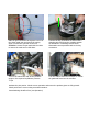
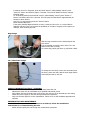
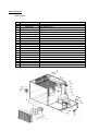
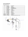
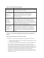
Table of Content
Page
0. Table of Content
2
1. Introduction
3
2. General Information
3
3. Safety
3
4. Handling and Transportation
4
5. Installation
4-5
6. Installation Procedure
5-6
7. Operation
7-9
8. Fault Finding
10-11
9. Parts Replacements
12-13
10. Technical Data
14
11. Wiring Schematic
15
12. System Schematic
15
13. Spare Parts List
16-18
14. Model Written Scheme of Examination
19-28
INTRODUCTION
The UltraFlow dispensing and cooling system is a self-contained, high speed mobile solution for busy
places. Developed to meet unique requirements of stadium and event outlets, it delivers beer to a
maximum number of consumers in the shortest possible time.
By use of intelligent technology, UltraFlow's high throughput system rapidly dispenses measured
volumes of beer into a glass or jug, at a consistent temperature and ensures head height, enhanced
clarity and freshness. Consumers no longer wait in frustrating queues, brand promise is guaranteed
and retailers offer a faster, more reliable service. Ultra Flow is designed to provide rapid dispense in
demanding environments of high volume retail.
GENERAL DESCRIPTION
UltraFlow's unique benefits include:
• Fast dispense rate of 4 seconds a pint or 5 seconds per ½ litre
• Superior quality and consistency of in-glass dispense
• Reduced queuing improves customer satisfaction
• Easy-to-use electronic control system permits use of low skilled staff
• High sales within a minimum of time
• Greater keg yield provided by reducing wastage
• Maximum mobility
SAFETY
Read this booklet before undertaking installation or maintenance.
Recognise safety alerts - isolate the power supply before removing panels or carrying out any
maintenance.
DANGER - Indicates an immediate hazardous situation which, if not avoided; WILL result in serious
injury, death, or equipment damage.
WARNING - Indicates a potentially hazardous situation which, if not avoided, COULD result in
serious injury, death, or equipment damage.
CAUTION - Indicates a potentially hazardous situation which, if not avoided, MAY result in minor or
moderate injury or equipment damage.
Safety Tips – Learn how to operate the Mobile Caddy unit and how to use the controls properly.
AUTHORIZED SERVICE PERSON
CAUTION- Only technicians who are competent with carbon dioxide (CO2) gas / mixed gas,
electricity and plumbing should service this unit. ALL WIRING AND PLUMBING MUST CONFORM TO
NATIONAL AND LOCAL CODES OF PRACTICE.
CARBON DIOXIDE (CO2) GAS WARNING
WARNING – CO2 Displaces Oxygen. If a CO2 gas leak is suspected, immediately ventilate the
contaminated area before attempting to repair the leak.
−
Secure CO2 /mixed gas bottles in an upright position.
−
Use Food suitable CO2 /mixed gas only
−
Remember that parts of the device are at operating pressure. Do not loosen or dismantle any
components at operating pressure.
−
Protect internal components against heat sources including sunshine
−
The CO2 /mixed gas bottle must be connected to a high pressure CO2 /mixed gas regulator. The
regulator must be date coded and compliant to local codes of practice.
HANDLING AND TRANSPORTATION
−
−
−
−
−
−
−
−
−
This unit is heavy, take care when moving
Offload the unit from transport as close as possible to the site of intended use
Use the handles provided to move the unit
Move the unit no faster than walking pace
Wherever possible, push the unit rather than pulling as this is ergonomically better and will
reduce the risk of foot trapping
Moving the unit on flat surfaces
o Keep your shoulder, hips and ankles in line, get the power from your legs
o Grip the unit at elbow height using the handle provided
o Don’t exert yourself to the maximum, get help if needed
o Be aware there may be sudden changes of resistance at the intersection of
different floor surfaces
o Plan in advance for stopping
Inclines and uneven surfaces
o Seek help from another person when moving up or down an incline and on
uneven surfaces
Keep the unit in an upright position and do not drag over rough floors or down steps.
On receipt, unpack the unit carefully and visually inspect for any damage which it may have
sustained in transit. Record the nature of the damage on the Courier’s Delivery Note and at the
same time inform your supplier
INSTALLATION
General
Installation must only be carried out by a suitably trained person and comply with national and local
codes for CO2 and electrical supplies. It is recommended that in all cases the installation is protected
by a RCCB (Residual circuit current breaker)
Siting
The Player Mobile Bar is suitable for outdoor use
The Player Mobile Bar shall not be exposed to rain DANGER
Indoor use:
The power supply cords of the Player Mobile Bar must be plugged directly into a grounded, 13amp,
230V socket which is protected by a circuit breaker and easily accessible for isolation of the cooler.
WARNING The socket shall be installed to current IEE regulations.
Outdoor use:
The power supply cords of the Player Mobile Bar must be plugged directly into an IP66
‘weatherproof’, grounded, 13amp, 230V socket which is protected by a circuit breaker and easily
accessible for isolation of the cooler. The socket shall be installed to current IEE regulations.
WARNING
The Player Mobile Bar is designed for ambient temperatures up to 32°C and should not be exposed to
water spillage, spray, steam or high humidity (in excess of 90%rh).
−
The unit must be sited on a firm, level surface
−
Allow 100mm clearance around the unit to aid air circulation
−
Air vents should never become obstructed or blocked
−
Access should be possible to the door for ease of keg change/gas change or service
−
Do not stand on this unit
Installation
−
The appliance must be earthed
−
If not already fitted, fit the appropriate electrical plug to the service cord
−
The device must be in satisfactory condition whenever operated. Any modifications which
detrimentally affect the safety of the device are therefore strictly prohibited. Please contact
your service company if you wish to obtain more information about safety
−
With the unit unpacked and in position do not connect to an electrical supply at this stage.
Requirements summary
The unit requires a bottle supply of CO2 /mixed gas and beer keg.
The unit also needs an earthed 13 Amp, 230v socket.
There are no other connections.
Only non – siphon type cylinders should be used. CO2 /mixed gas cylinders should always be secured
vertically with the outlet valves in the uppermost position to prevent injury through ingress of liquid
carbon dioxide into the pressure regulators(s). On no account should a connection be attempted to a
CO2 /mixed gas cylinders other than a purpose made high pressure assembly, which is date coded in
accordance with the relevant code of practice.
INSTALLATION PROCEDURE
Commissioning
Dismantle the unit, to get access to the cooling system and the electric devices.
Fill the water bath with water, until the level
has reached the pointed height of the water
gauge.
Energize the cooling device and allow the
system to build up an ice bank.
At least 4-5 hours!
Slide the gas connection through the cut out of
the sheet metal part and mount the casing
again. Connect the gas tank to the unit.
WARNING: Secure the gas tank with the chain
to ensure the tank can not fall down.
Connect the keg connection as shown with a
cleaning tank and clean the complete system
as described in “Sanitizing Product Coils”.
Afterwards connect product tank to the keg
connection.
Turn on the CO2 bottle and set the pressure
gauge to the required equilibrium pressure
+5 psi
Turn the switch at the beer monitor to release
the gathered foam into the overflow.
Activate the pint portion. Check correct operation and ensure the product pipes are fully primed.
Check portions are correct using a marked container.
Commissioning UltraFlow font (see Operation)
OPERATION
Programming
Normal display will read “Ready”
Press and hold “Cancel” button (red lights will alternate on Keg and gas empty)
Display will show pint and jugs dispensed. (these readings cannot be altered).
Press “Portion 2” button to scroll trough the menu:
Press “Portion 2” display will read “pint set up”
Press “Portion 2” display will read “Jug set up”
Use the “Portion 1” and “Top up” buttons to alter value (this applies to all settings)
Press “Portion 2” display will read “Hit (ms)” 100 – Do not alter this value
Press “Portion 2” display will read “Hold (%) 020 – Do not alter this value
Press “Portion 2” display will read “Pint Timeout” – Do not alter this value
Press “Portion 2” display will read “Jug timeout” 40.0 – Do not alter this value
Press “Portion 2” display will read “Drain Time” 03.0 – Do not alter this value
Press “Portion 2” display will read “Drain delay” 100 - Do not alter this value
Press “Portion 2” display will read “Beer saver” 3500 - Do not alter this value
Press “Portion 2” display will read “Top up valves 2. Alter between 1 valve or two valves. 1 is
for foam, 2 is for clear beer.
To exit the program press “Cancel”
If settings are lost or forgotten, press and hold “Cancel”, whilst holding “Cancel” press
“Portion 2” button and hold for approx 5 seconds. The unit will default to factory settings.
Cleaning mode:
To set cleaning mode press and hold “cancel”, whilst holding “cancel” press “Portion 1”
button, hold both buttons for 5 seconds. This will open the solenoids for approximately 20
minutes to allow fluid to
free flow. To stop cleaning press the “Cancel” button.
Glass activated dispense:
If the glass activated dispense button is used, it must be held on for ½ a second before
dispense will start. This is to prevent the possibility of “nuisance” tripping of the system, for
example, when cleaning the font.
Keg change
Slide the keg connection on the tank and push the
lever down.
It is not possible to push the lever down if it is not
slided on the tank correctly.
To remove keg, simply pull lever up, and slide it back.
CO2 /Mixed Gas Change
To change the CO2 tank, remove the connection and
the chain, place new tank, add the chain again before
connecting the tank to the unit.
SERVICE INFORMATION (FAULT / REPAIRS)
−
There are NO ‘user’ (OPERATOR) serviceable items inside the unit
−
Maintenance must only be undertaken by a qualified and trained person
−
Only replace the fuse protecting the circuit to the unit with one of an identical type and rating
−
Isolate the power supply to the unit during maintenance operations
−
Only use Cornelius parts for cooler maintenance. Failure to do so will invalidate approvals and
warranty
PREVENTATIVE USER MAINTENANCE
For all of the below, once the maintenance is carried out, follow the Installation
instructions for re commissioning the unit
−
Switch off and unplug the unit during user maintenance operations
−
−
In the event of the unit malfunctions or suffers spillage or physical damage, unplug the unit
from its electrical supply
Do not switch the unit ‘off’ and ‘on’ within five minutes
Sanitizing Product Coils
−
Under no circumstances should boiling water or steam be used with this unit as it may result in
permanent damage. The maximum temperature permissible is 40°c
−
Sanitize when taste is tainted or periodically as advised by the beverage supplier.
−
Cleaning process
The system will require thoroughly cleaning using a recognized beer line cleaner followed by
sufficient clean water to neutralize the system.
Employ the standard procedure when cleaning the system i.e. allow the beer line cleaner to
remain in the system for approximately 15 to 20 minutes drawing fresh cleaner through the
system by operating the pint portion button at approximately 5 minute intervals during the 20
minute soak then thoroughly rinse with clean water using the jug portion button The system
can now be connected to a product keg and primed ready for use.
PLEASE NOTE: When the CO2 supply becomes exhausted the CO2 cut out switch is set to
operate before the line pressure falls below product equilibrium. This will help to ensure that
CO2 breakout is kept to an absolute minimum. Once the CO2 supply is reinstated the font will
automatically resume normal operation. If the product keg empties the system will allow
completion of the last portion before stopping normal dispense operation. Normal operation
will automatically resume when new a product keg is connected to the system.
Cleaning
−
Clean parts coming into contact with air and beverage, the mouth of the tap for example, on a
daily basis
−
The external faces of the unit should only be wiped down with a damp cloth. Any cleaning
materials should be non-abrasive. Do not use any chemicals to clean.
- The condenser fins must be cleaned at regular intervals (approx. Every 3 months). This is best
done with a brush and vacuum cleaner.
Periodic Testing
The 1989 Electricity at Work Regulations require periodic testing of electrical equipment and this
should only be carried out by a competent person
Daily Inspection
−
Check the beverage line for leaks. Only a visual inspection is possible. If liquid escapes, call a
service technician.
−
Check the CO2-line for leaks by closing the cylinder globe valve on the CO2-cylinder. The inlet
pressure indicated on the pressure regulator should not drop. If it does, call a service technician
immediately (upon successfully passing this test do not forget to re-open the cylinder valve
afterwards)
Putting out of Service
Perform the following steps in case of protracted periods without use
−
Have the device emptied and cleaned. Only trained specialists are to carry out this procedure
−
Close the CO2-cylinder (valve on top)
−
Pull the mains plug out of socket
−
Detach the couplings from beverage containers & CO2 cylinder.
−
Pull the UltraFlow tower out of the socket and lay it down on the top of the mobile bar and fix
it.
Parts replacement
Technical data
Wiring Schematic / System Schematic
Spare parts list
CR11 Cooler
Item Part code
52
220055105
56
143277000
NS
220055074
47
440000236
51
189722000
49
131706000
50
187888000
1
440000704
40
220055172
12
220055102S010
43
147029434
53
58 0446 241
7
141647307
11
142500520
10
220055198
27
220055712S003
25
220098234
23
149550255
24
143350000
41 220094917S019
Description
BASE SHEET CR11
ADJUSTING FOOT
OVERFLOW TRAY CHROME - SC
COMPRESSOR GS 34 TB
BOLT
BUFFER VIBRATION 32x23
CLAMP
CONDENSER STVF 273
WATERBATH CR11
SHEET METAL HOUSING WATERBATH TRITON 250
EXPANSION VALVE TUC 4
MAINS CABLE
CONTROL + BOX CPL. ICEBANK
ICEBANK PROBE 3 PIN
SUPPORT BRACKET ICEBANK PROBE CR11
TIE BAR AGITATOR CR7
RUBBER BUFFER AGITATOR
AGITATOR 5/1 CR 4-7
AGITATOR PROPELLER Ø60M5
COOLING COILS ASSEMBLY 4 X 10M
53
Model Written Scheme of Examination for Mobile “Player” Bar
This scheme should be completed by the nominated technical person
or by a technician on behalf of the nominated technical person.
Notes on BBPA Code of Practice Competent Person
The design, installation and use of equipment for the pressurised dispense of beer and
cider all come to some degree under the Pressure Equipment Regulations 1999, SI
1999 No. 2001(PER) and the Pressure Systems Safety Regulations 2000, SI 2000 No.
128.
It is important that retailers, licensees, design engineers, contractors, owners and users
of such equipment understand their responsibilities for the safety of pressure systems.
The Code of Practice for the Dispense of Beer by Pressure Systems in Licensed
Premises (updated 2005) has been produced by the British Beer and Pub Association
to assist the above mentioned persons to comply with the Pressure Regulations
requirements.
The Code clearly suggests the mechanical and organisational requirements for fixed
installations to enable compliance with the regulations.
Although primarily intended for fixed (cellar) installations it refers to the need for
similar controls on mobile/portable installations.
To enable these controls to operate and ensure safe use of pressure dispense
equipment it defines certain responsibilities for “Authorised” persons, “Competent”
persons, owners and users of pressure systems.
Of these the most important is the “Competent” person who must have sound
practical and theoretical knowledge of the pressure systems and allied equipment used
in beer dispense and the appropriate legislation.
Such a person will be able to detect errors or deficiencies in any proposed design, and
identify those elements of the system which will require periodic examination.
He/she will also draw up and/or certify that the written scheme and examination
process are adequate.
In the case of mobile bars it is suggested that a separate written scheme is introduced
for each model of unit taking into account the amount of use and the complexity of
equipment involved.
Text for further reading:BBPA Code of Practice for the Dispense of Beer by Pressure Systems 2005 (Brewing
Publications Ltd)
The Pressure Systems Safety Regulations 2000 (SI 2000 No. 128)
The Pressure Equipment Regulations 1999 (SI 1999 No. 2001)
Instructions for the Safe Operations of Gas Pressure Systems used in the Dispensing
of Beers and Lagers published 1998 by Brewing Publications Ltd.
Model Scheme for mobile “Player” bar. Mod 28.08.08
Company Name
Department Name
Written Scheme of Examination for Mobile Dispense system Using Top Pressure
Gas
Used in the storage and dispense of Draught Beers Wines and Ciders
Written scheme number
Prepared for: Company Name
Company Address
Post Code
Tel
Fax
By Dick Ward
IMI Cornelius UK Ltd
Tything Road
Alcester
Warks. B49 6EU
Tel 01789 763101
Fax
Name and Address of Owner
Name
Address
Post Code
Tel.
Fax.
Pressure System Types
1 Carbon Dioxide Pressure System
2 Carbon-Dioxide/Nitrogen Mixed Gas System
Location of Records
Address(es) of Record Locations
Tel :
Fax :
Scope of this Written Scheme of Examination
This Written Scheme of Examination applies to mobile pressure systems that:
a) are operated within licensed event areas.
b) Are used for distribution of top pressure gases used for the storage and
dispense of draught
c) beers, wines and ciders; and
d) Fall within the requirements of “The Pressure Systems Safety Regulations,
2000”.
Only items of plant contained within the mobile system that:
Company Name own; or
Company Name own and use; are included under this written scheme.
This written scheme of examination consists of five sections:
Section 1 : Plant to be Examined
Section one identifies the items of plant, within the pressure systems, subject to
periodic examination. These items are identified by reference to a block diagram for
the generic pressure systems used.
Section 2 : Items of Plant not to be Examined under this Scheme
Section two contains, where appropriate, items of plant within the pressure systems
that are not subject to periodic examination under this written scheme. Some of these
items of plant may be subject to periodic examination under some other written
scheme of examination.
Section 3: Preparation and Examination Procedures
Section three specifies the nature of any periodic examination that may be required,
including any preparatory work necessary to prepare the plant for examination.
Section 4: Review Dates
Section four states the requirements for reviewing the written scheme of examination.
Section 5 : Modifications
Section five records any modifications to the written scheme of examination arising
from the formal review, or due to any other reason.
Legislation
The pressure systems used for the storage and dispense of draught beers, wines and
ciders are simple. They must comply with legislation. The following Regulations
concern the pressure systems, and the components used in their assembly:
1) The Pressure Systems Safety Regulations 2000 (SI2000 No. 128)
2) The Pressure Equipment Regulations 1999 (SI 1999 No.2001)
3) “The Carriage of Dangerous Goods and Use of Transportable Pressure Equipment
Regulations 2004” (SI 2004 No. 568)
Related Documents
a) “Code of Practice for the Dispense of Beer by Pressure Systems in Licensed
Premises 1994”, published by Brewing Publications Ltd, June 1994.
b) “Code of Practice for the Dispense of Beer by Pressure Systems in Licensed
Premises 2005”, published by Brewing Publications Ltd, January 2005.
c) “Instructions for the Safe Operation of Gas Pressure Systems used in the
Dispensing of Beers and Lagers”, published by Brewing Publications Ltd,
April 1998.
d) Product Manual and Operating Instructions.
Section 1 – Items of Plant to be Examined
The pressure systems used for controlling pressure in dispense and storage
systems
installed in this mobile unit are defined within the Regulations (SI 2000 No.128)
as “installed systems”. The pressure systems are also defined as “assemblies” of
pressure equipment within the Pressure Equipment Regulations. This gives
exemption from regulations 4 and 5(1) and (4) of The Pressure Systems Safety
Regulations.
A block diagram Figure 1 is used to describe the pressure system used within the
specific model of mobile unit. Table 1 describes the various blocks.
In figure 1 the parts of the plant that fall within the scope of this written scheme
are contained within the blocks labeled “primary/secondary pressure reducing
system”. This integral unit contains a primary pressure-reducing element close
coupled to a secondary pressure-reducing element, each stage having two
protective pressure relief (safety) valves. The items of plant requiring examination
are the primary pressure-reducing element in the “primary pressure reducing
stage” (normally a pressure-reducing valve, several types being normally used)
and the two pressure relief (safety) valves of both stages.
Figure 1 : Block Diagram of Pressure System for “Player” Mobile unit used
for Storage and Dispense of Draught Beers and Ciders, when using the
principle of examination by replacement.
Integral Primary/Secondary Pressure
Pressure
Reducing System with Primary and
Source
Secondary Protection.
Table 1 : Description of Blocks in Figure 1
BLOCK
CHARACTERISTICS
Pressure Source
CO2 Cylinder; Mixed Gas Cylinder
Primary Reducing
System/
Primary Safety
Valves
Inlet max. allowable pressure: to suit pressure source;
Capacity: max. 66 litres/minute with full cylinder.
Maximum allowable outlet pressure to secondary:
150 psig for all gases.
Primary Inter-stage
ProtectionProtecting
Secondary stage
components.
2 x Pressure Relief (Safety) Valves mounted on Primary
Pressure Reducing Valve: remain seated up to set pressure
+10%; re-seat by set pressure -10%; capacity of each valve:
minimum 67 litres free gas /minute at max. set pressure +10%.
Maximum allowable Inter-stage pressure = set pressure + 10%.
Maximum set pressures: 150psig for all gases.
Close-coupled
Secondary Control
Valve with
secondary supply
protection.
Integral Secondary Pressure Reducing Valve with 2 x pressure
relief (safety) valves, mounted close in-line; capacity not
greater than the Primary Safety Valve; set relief pressure
(45psig) below max. safe working pressure of downstream
equipment; relieving capacity greater than secondary valve
capacity.
Section 2 – Items of Plant NOT Requiring Examination Under this Written
Scheme
Items of Plant Exempted Under this Written Scheme
The Regulations except some items of plant from examination. Such items are:
1) kegs (of volume less than 0.252m3 and maximum working pressure less than
12 bar above atmospheric);
2) any small vapour compression plants (less than 25kW total installed power).
Items of Plant not Requiring Examination under this Written Scheme
Items of plant are not intended to be examined on a regular, defined basis, if it is
not anticipated that deterioration will develop and propagate, or which are of a
size and nature or installed in a location such as not to constitute a danger in the
event of failure. (To qualify for the permitted exception from periodic
examination, items of plant should meet at least one of these conditions, in all
installations to which this written scheme applies. The competent person must be
satisfied that this is so.)
Examples of such items of plant not requiring periodic examination under this
written scheme include:
Gas piping and tubing; piping/tubing/line fittings; secondary pressure reducing
valves.
Plant and Pressure Systems not included in this written Scheme of
Examination
This written Scheme of Examination does not cover:
Any part of the mobile equipment of which the Brewery Company
Name/Supplier is neither the owner or user.
Any transportable pressure receptacle (ie compressed gas cylinders), which are
subject to other examination regimes by their owners;
Section 3 – Preparation and Examination Procedures
3.1 Initial Examination
All units are supplied new or refurbished, pre-set (where possible) and tested.
There is no requirement for further examination before the unit is put into use.
3.2 Equipment Repairs on Site
No major repairs should be undertaken on site. Repairs to the pressure system
should only be carried by competent trained service personnel.
3.3 Examination by Replacement
The specified parts of the pressure system in this mobile unit will be subject to
examination by replacement.
Nature of Examination
All items identified for examination in section 1 as requiring periodic
examination will be “examined by replacement”.
(This does not preclude a change to on-site testing. Before any change is
introduced into any examination procedure, the competent person must agree
the new regime in writing. Any amendments to the written scheme must be
introduced before the new/modified procedure is put into practice. Adequate
training of affected personnel is essential).
Examination by Replacement
Preparation:
Prior to removal of any component part of the pressure system, the system
should be isolated from any source of pressure and the internal pressure
relieved.
Removal:
The part, or assembly of parts, specified to be “examined by replacement”
shall be removed with care and diligence so as not to cause any damage or
deterioration to either the parts or connecting parts in the system. The removed
parts shall be returned to original manufacturer/repairer for testing and
recording of results prior to refurbishment. Care should be taken to minimize
transit damage.
Replacement:
Replacement parts shall be new or refurbished to current standard.
Replacement must be performed in such a manner that will not cause damage
to the parts in question or connecting parts of the system. New or refurbished
parts must perform to the same operational parameters as the parts being
replaced. No modifications or adjustments shall be made to the parts or system
unless specifically required by the specification.
Personnel:
Only competent trained personnel are allowed to carry out examination by
replacement.
A record is to be kept of personnel deemed competent and trained for these
duties and they should be made aware of their responsibilities.
Records:
Records of the examination/replacement on the specific mobile unit are to be
updated at time of replacement with an indication of next due examination
date. Where a part is replaced during normal service/operation, the next
examination date remains unchanged.
3.4 Period between examinations:
A maximum period between examinations for the pressure system parts is 5
years.
The high pressure hose feeding the primary regulator should be examined for
damage annually.
In addition the electrical parts of the unit will require examination and PAT
test at maximum of 12 month periods.
3.5 Response to Imminent Danger:
The competent person must, in the event of discovering a material condition
which could give rise to imminent danger, inform the owner/owner
representatives of the condition and ensure the unit is taken out of use until
such condition/s has been rectified.
Section 4 –Review
Review of the Written Scheme
A review by a competent person of this written scheme will take place
annually.
If the review recommends any modifications to this written scheme, the
scheme will be so modified.
The following record of review will be kept:
Date of review
of competent person
State if modified (yes or no)
Signature
Section 5 – Modifications
Modifications to this written scheme
Modifications to this written scheme will be recorded in the table below.
Date of modification
competent person
Description of modification Signature of