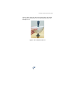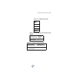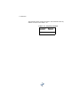
1
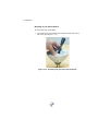
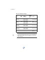
Crescent V100 Series
User Guide
Part No. 875-0174-000 Rev. A1
This device complies with Part 15 of the FCC rules. Operation is subject to the following
two conditions:
•
•
This device may not cause harmful interference.
This device must accept any interference received, including interference that may
cause undesired operation.
Copyright Notice
Hemisphere GPS Inc. Precision GPS Applications
Copyright © Hemisphere GPS (2007). All rights reserved.
No part of this manual may be reproduced, transmitted, transcribed, stored in a retrieval
system or translated into any language or computer language, in any form or by any
means, electronic, mechanical, magnetic, optical, chemical, manual or otherwise, without
the prior written permission of Hemisphere GPS Inc.
Trademarks
Hemisphere GPS and the Hemisphere GPS logo, Satloc and the Satloc logo, Mapstar, Air
Star Outback Guidance and eDrive are trademarks of Hemisphere GPS. Other trademarks
are the properties of their respective owners.
Notice to Customers
Contact your local dealer for technical assistance. To find the authorized dealer near you,
call or write us at:
Hemisphere GPS
4110 9 Street S.E.
Calgary, AB, Canada
T2G 3C4
Telephone number: (403) 259-3311
Fax number:
(403) 259-8866
E-mail address:
[email protected]
Warranty Notice
COVERED PRODUCTS
This warranty covers all products manufactured by Hemisphere GPS Inc. (the
"Products").
HEMISPHERE GPS INC. LIMITED WARRANTY
Hemisphere GPS Inc. hereby warrants solely to the end purchaser of the Products,
subject to the exclusions and procedures set forth herein below, that the Products sold to
such end purchaser shall be free, under normal use and maintenance, from defects in
material and workmanship for a period of 12 months from delivery to such end purchaser.
Repairs and replacement components are warranted, subject to the exclusions and
procedures set forth below, to be free, under normal use and maintenance, from defects
in material and workmanship for 90 days from performance or delivery, or for the balance
of the original warranty period, whichever is greater.
PURCHASER'S EXCLUSIVE REMEDY
The end purchaser's exclusive remedy under this warranty shall be limited to the repair or
replacement, at the option of Hemisphere GPS, of any defective Products or components
thereof. The end user shall notify Hemisphere GPS or a Hemisphere GPS approved service
center immediately of any claimed defect. Repairs shall be made through a Hemisphere
GPS approved service center only.
EXCLUSIONS
Hemisphere GPS does not warrant damage occurring in transit or due to misuse, abuse,
improper installation, neglect, lightning (or other electrical discharge) or fresh/salt water
immersion of Products. Repair, modification or service of Hemisphere GPS products by
any party other than a Hemisphere GPS approved service center shall render this
warranty null and void. Hemisphere GPS does not warrant claims asserted after the end
of the warranty period. Hemisphere GPS does not warrant or guarantee the precision or
accuracy of positions obtained when using Products. Products are not intended for
primary navigation or for use in safety of life applications. The potential accuracy of
Products as stated in Hemisphere GPS literature and/or Product specifications serves to
provide only an estimate of achievable accuracy based on:
•
•
Specifications provided by the US Department of Defense for GPS Positioning,
DGPS service provider performance specifications.
Hemisphere GPS reserves the right to modify Products without any obligation to notify,
supply or install any improvements or alterations to existing Products.
NO OTHER WARRANTIES
THE FOREGOING WARRANTY IS EXCLUSIVE OF ALL OTHER WARRANTIES, WHETHER
WRITTEN, ORAL, IMPLIED OR ARISING BY STATUTE, COURSE OF DEALING OR TRADE
USAGE, IN CONNECTION WITH THE DESIGN, SALE, INSTALLATION, SERVICE OR USE OF
ANY PRODUCTS OR ANY COMPONENTS THEREOF, INCLUDING, BUT NOT LIMITED TO,
ANY WARRANTY OF MERCHANTABILITY OR FITNESS FOR A PARTICULAR PURPOSE.
LIMITATION OF LIABILITY
THE EXTENT OF HEMISPHERE GPS' LIABILITY FOR DAMAGES OF ANY NATURE TO THE
END PURCHASER OR ANY OTHER PERSON OR ENTITY WHETHER IN CONTRACT OR TORT
AND WHETHER TO PERSONS OR PROPERTY SHALL IN NO CASE EXCEED, IN THE
AGGREGATE, THE COST OF CORRECTING THE DEFECT IN THE PRODUCT OR, AT
HEMISPHERE GPS' OPTION, THE COST OF REPLACING THE DEFECTIVE ITEM. IN NO
EVENT WILL HEMISPHERE GPS BE LIABLE FOR ANY LOSS OF PRODUCTION, LOSS OF
PROFITS, LOSS OF USE OR FOR ANY SPECIAL, INDIRECT, INCIDENTAL, CONSEQUENTIAL
OR CONTINGENT DAMAGES, EVEN IF HEMISPHERE GPS HAS BEEN ADVISED OF THE
POSSIBILITY OF SUCH DAMAGES. WITHOUT LIMITING THE FOREGOING, HEMISPHERE
GPS SHALL NOT BE LIABLE FOR ANY DAMAGES OF ANY KIND RESULTING FROM
INSTALLATION, USE, QUALITY, PERFORMANCE OR ACCURACY OF ANY PRODUCTS.
GOVERNING LEGISLATION
To the greatest extent possible, this warranty shall be governed by the laws of the State
of Arizona. In the event that any provision hereof is held to be invalid by a court of
competent jurisdiction, such provision shall be severed from this warranty and the
remaining provisions shall remain in full force and effect.
OBTAINING WARRANTY SERVICE
In order to obtain warranty service, the end purchaser must bring the Product to a
Hemisphere GPS approved service center along with the end purchaser's proof of
purchase. For any questions regarding warranty service or to obtain information
regarding the location of any of Hemisphere GPS' approved service centers, contact
Hemisphere GPS at the following address:
Hemisphere GPS Inc.
7560 East Redfield Road, Suite B
Scottsdale, Arizona 85260
Phone 480.348.9919 Fax 480.348.6370
[email protected]
http://www.hemispheregps.com
Crescent V100 Series User Guide
Table of Contents
Overview . . . . . . . . . . . . . . . . . . . . . . . . . . . . . . . . . . . . 1
1: INSTALLATION . . . . . . . . . . . . .3
Mounting Location . . . . . . . . . . . . . . . . . . . . . . . . . . . . . 4
GPS Reception 4
Beacon Reception 5
Crescent V100 Environmental Considerations 6
Mounting Orientation 6
Crescent V100 Alignment 7
Mounting Options . . . . . . . . . . . . . . . . . . . . . . . . . . . . . 9
Fixed-Base Mounting 9
Pole and Rail Mount 16
Powering the Crescent V100 . . . . . . . . . . . . . . . . . . . . 28
Power Considerations 28
Connecting to a Power Source 28
Electrical Isolation 29
Connecting the Crescent V100 to External Devices . . 30
Interfacing the Crescent V100 30
Power/Data Cable Pin-Out 30
Serial Port Interface 34
Serial Port Configuration 35
Interfacing to a PC 35
Default Parameters 37
i
2: CRESCENT V100 OPERATION 43
GPS Overview . . . . . . . . . . . . . . . . . . . . . . . . . . . . . . . 44
GPS Operation 44
Differential Operation 45
Understanding the Crescent V100
. . . . . . . . . . . . . . . 48
Moving Base Station RTK 48
Supplemental Sensors 49
Tilt Aiding 50
Gyro Aiding 51
Time Constants 52
Alarm Functionality . . . . . . . . . . . . . . . . . . . . . . . . . . . 54
Alarm Signal 54
Watchdog 54
Common Commands and Messages . . . . . . . . . . . . . . 55
APPENDIX A:
TROUBLESHOOTING . . . . . . . . . .61
APPENDIX B: SPECIFICATIONS
.67
APPENDIX C: PARTS LIST . . . . .73
Index . . . . . . . . . . . . . . . . . . . . . . . . . . . . . . . . . . . . . . 77
ii
Crescent V100 Series User Guide
OVERVIEW
Welcome to the Crescent V100/V110 GPS Compass User Guide and
congratulations on purchasing this high-performance GPS
compass. The Crescent V100 is based upon Hemisphere GPS’
exclusive Crescent®-branded, application-specific integrated circuit
(ASIC) computer chipset technology.
Note: The Crescent V100/V110 GPS Compass will be referred to
as the Crescent V100.
The Crescent V100 is a complete GPS compass and positioning
system in a single enclosure that requires only one power/data
cable connection. The Crescent V100 is designed primarily for the
marine market, however, it is also suitable for other markets, such
as machine control and agriculture guidance. This user guide
addresses the primary use of the Crescent V100 in the marine
industry, however, the information provided is broad enough to
satisfy the needs of the Crescent V100 use in other markets.
The Crescent V100 is an integrated system that houses the
Crescent Vector OEM module, dual GPS antennas, DGPS beacon
module and H-field beacon antenna (Crescent V110 version only),
power supply, single axis gyro and a tilt sensor. The gyro and tilt
sensor are present to improve system performance and to provide
backup heading information in the event that a GPS heading is not
available due to signal blockage.
Note: The Crescent V100 model is identical to the V110 with the
exception that it does not contain a DGPS beacon module. If you
purchased the Crescent V100, please ignore the sections of this
manual that discuss the beacon signal, receiver operation and
implications to installation relating to the beacon signal.
Crescent technology supports multiple RF front ends - enabling
tighter coupling of measurements from separate antennas for use
in heading-based products. Users will achieve excellent accuracy
and stability, due to Crescent’s more accurate code phase
1
measurements, improved multipath mitigation and fewer
components.
The GPS antennas inside the Crescent V100 are separated by 0.5
meters (0.55 yards) between antenna phase centers, resulting in a
0.30° RMS heading performance. The Crescent V100 provides
heading and positioning updates of up to 20 Hz and delivers
positioning accuracy of 60 centimeters (23.62 inches) 95% of the
time and 0.30° RMS with 50 centimeter (19.69 inches) antenna
separation (when using Differential GPS corrections from Space
Based Augmentation Systems (SBAS)) or its optional internal SBX
beacon demodulator.
The Crescent V100 also features Hemisphere GPS’ exclusive
COAST™ software that enables Hemisphere GPS’ receivers to
utilize old differential GPS correction data for 40 minutes or more
without significantly affecting the quality of positioning. When
using COAST, the Crescent Vector OEM is less likely to be affected
by differential signal outages due to signal blockages, weak signals
or interference.
If you are new to GPS and SBAS, we recommend that you consult
Hemisphere GPS’ GPS Technical Reference manual for further
information on these services and technologies before proceeding.
2
1: INSTALLATION
Mounting Locations
Mounting Options
Powering the Crescent V100
Connecting the Crescent V100 to External Devices
1: Installation
MOUNTING LOCATION
When considering mounting locations, you will need to give regard
for both GPS (and hence SBAS) and beacon reception. The
following two sections provide information that will help determine
the best location for the Crescent V100.
GPS Reception
When considering various locations to mount the Crescent V100,
consider the following recommendations closely.
•
The Crescent V100 computes a position based upon the
internal primary GPS antenna element. Mount the
Crescent V100 in the location for which you desire a
position with respect to the primary GPS antenna, which is
located on the end opposite the recessed arrow on the
underside of the enclosure.
•
When choosing a location to mount the antenna, please
ensure that there is a clear view of the sky available to the
Crescent V100. This will ensure that GPS and SBAS
satellites are not masked by obstructions, potentially
reducing system performance.
•
It is important to locate any transmitting antennas away
from the Crescent V100 by at least a few feet. This will
ensure that tracking performance is not compromised,
giving you the best performance possible.
•
Make sure that there is enough cable length to route into
the vessel, in order to reach a breakout box or terminal
strip.
•
Do not locate the antenna where environmental conditions
exceed those specified in Table B-6 in the appendix.
4
Crescent V100 Series User Guide
Beacon Reception
When using the V110’s internal beacon receiver as the correction
source, you will need to consider the possible mounting locations
from a perspective of ambient noise within the beacon band. The
following list provides some general guidelines for deciding upon a
location with respect to maximizing beacon performance.
•
Ensure that the antenna is as far as possible from all other
equipment that emits Electromagnetic Interference (EMI),
including DC motors, alternators, solenoids, radios, power
cables, display units and other electronic devices.
•
If you are installing the antenna on a vessel, mount the
V110 as high as possible, considering maintenance and
accessibility. In addition, ensure that the antenna is higher
than the highest metal object on the vessel.
•
If a radar system is present, mount the antenna outside
the path of the radar beam.
The V110’s internal beacon receiver calculates a Signal to Noise
Ratio (SNR), measured in decibels (dB), that indicates the
receiver’s performance. The SNR is height of the signal above the
noise floor. The higher the SNR, the better your beacon receiver is
demodulating the signal. The optimum antenna location will be a
position where your average SNR is highest. You should turn on all
accessories that you intend to use during normal operation when
locating the best position for the antenna. By monitoring the SNR,
you can determine the optimum location with respect to beacon
reception. The SNR is available in the $CRMSS NMEA message
described in Hemisphere GPS’ GPS Technical Reference manual.
5
1: Installation
Crescent V100 Environmental Considerations
The Crescent V100 is designed to withstand the harsh outdoor
environment, however, there are specific environmental limits that
should be met when storing and using this system.
The Crescent V100 is designed to be stored between -40° C and
+85° C (-40° F and +185° F). The operating temperature range is
-32° C and +74° C (-25.6° F and +165.2° F). It is designed for harsh
marine use and will operate in an environment with 100% relative
humidity.
Mounting Orientation
There are two primary mounting orientations possible with the
Crescent V100 system. The first and most common method is to
mount the Crescent V100 enclosure pointing in a direction parallel
to the axis of the boat, facing the bow. This mounting configuration
provides the ability for the Crescent V100 system to output both
heading and the pitch of the vessel.
If a gyrocompass is present onboard, this could be used as truth to
calibrate the physical heading of the Crescent V100 and its
corresponding heading measurements to true heading of the boat
by entering a heading bias into the Crescent V100 configuration.
For example, if a gyrocompass heading provides 183.2° while the
Crescent V100 provides a heading of 184.0, a bias of -0.8 (the bias
is added) should be programmed into the Crescent V100 to
calibrate its heading. The Crescent V100 could be physically
adjusted to correct for this deviation.
6
Crescent V100 Series User Guide
The second method of mounting the Crescent V100 system is to
mount the Crescent V100 perpendicular to the boat’s symmetrical
axis. This orientation will provide the heading and roll of the vessel.
The Crescent V100 is then configured with a heading bias of +90°
or -90°, depending if the Crescent V100 points to port or starboard,
to correct the heading.
A feature is present in the Crescent V100 to change the sign of the
roll/pitch measurement to be positive or negative, depending on
the required conversion for positive/negative roll, if needed.
Consult Hemisphere GPS’ GPS Technical Reference manual for
further information.
Crescent V100 Alignment
The top of the Crescent V100 enclosure incorporates a pair of sight
design features for assisting antenna alignment. The sights will
help you to align the enclosure with respect to an important feature
on your vessel. (See Figure 1-1 and Figure 1-2 on page 7 and page
8.)
To use the sights, center the small post on the opposite side of the
enclosure from you, within the channel made in the medallion
located in the center of the enclosure top as shown in the two
following figures. Alignment accuracy when looking through the
long site is approximately +/- 1°. Using the short site alignment is
approximately accurate to +/- 2.5°.
Figure 1-1. Lining up the alignment sight
7
1: Installation
Figure 1-2. Correctly lined-up alignment sight
If you have another accurate source of heading data on your
vessel, such as a gyrocompass, you may use its data to correct for
a bias in Crescent V100 alignment within the Crescent V100
software configuration. Alternatively, you may wish to physically
adjust the heading of the Crescent V100 so that it renders the
correct heading measurement, however, adding a software offset is
an easier process.
8
Crescent V100 Series User Guide
MOUNTING OPTIONS
The Crescent V100 allows for two different mounting options:
•
Fixed-base mounting
•
Pole-and-rail mounting
Fixed-Base Mounting
The fixed base supplied with the Crescent V100 is intended to allow
you to mount the system to a flat surface. This surface may be
something that you fabricate for the sake of the installation, or
may be something that already exists on your vessel or an
off-the-shelf item, such as a radar mounting plate.
Figure 1-1, on page 5, shows the following features for the fixed
base:
•
Six holes for mounting onto the Crescent V100 enclosure
•
Four slots used for fastening the mounted enclosure to the
vessel
•
Four tunnels that allow you to route the cable outside the
base and along the mounting surface
•
Two small keys that aid the alignment of the base to the
enclosure
•
Channel through the mount for the power/data cable
The slots on the bottom of the base allow for a degree of
adjustment when the Crescent V100 is secured in its final location.
Note: You do not necessarily need to orient the antenna
precisely as you can enter a software offset to
accommodate for any bias in heading measurement due to
installation.
9
1: Installation
The base has four tunnels that allow you to bring the power/data
cable out from within the mount in order to route it along the
surface of the plate beneath the Crescent V100 system.
Alternatively, you may wish to route the power/data cable through
the mounting surface rather than bringing it out through one of the
tunnels. (See Figure 1-3.)
Figure 1-3. Fixed mount base
Figure 1-4 provides a bottom view of the fixed mount base.
Figure 1-4. Bottom view of fixed mount base
10
Crescent V100 Series User Guide
Before mounting the antenna on the fixed base:
•
Decide if you need the roll measurement. If you do, the
Crescent V100 will need to be installed perpendicular to
the vessel axis. If you do not require roll, install the
Crescent V100 parallel with the vessel’s axis
(See Figure 1-5)
Recessed arrow located
on bottom of enclosure
.
Perpendicular
(roll) installation
Parallel (pitch)
installation
Figure 1-5. Crescent V100’s parallel perpendicular
installation
•
Choose a location that meets the mounting location
requirements.
•
Using the fixed base as a template, mark and drill the
mounting holes as necessary for the mounting surface.
11
1: Installation
Routing the cable
To install the Crescent V100 using the fixed base:
1.
Insert either end of the power/data cable through the center of
the fixed base. (See Figure 1-6 and Figure 1-7 on page 12 and
page 13.)
Figure 1-6. Running cable through fixed base mount
12
Crescent V100 Series User Guide
Figure 1-7. Running cable through fixed base
2.
Align the connector keyway of the cable to the key of the
connector mounted on the Crescent V100 enclosure. (See
Figure 1-8.)
3.
Insert the cable mount connector into the bulkhead connector,
aligning the locking ring at the same time. (See Figure 1-8.)
Connector
Key
Connector
Keypad
Figure 1-8. Power/Data cable and keyway
13
1: Installation
4.
Once inserted, rotate the ring clockwise until it locks. The
locking action is firm, but you will feel a positive “click” when it
has locked. (See Figure 1-9.)
Figure 1-9. Connecting the power/data connector to
Crescent V100
5.
Once you have secured the connector, slide the fixed base up
to the bottom of the Crescent V100 enclosure. There are two
alignment keys on top of the base that just fit into two holes of
the Crescent V100 enclosure.
6.
Once you have aligned the base, use a screwdriver fitted with
the supplied Torx T20 bit to fasten the base to the enclosure
using the supplied screws. These screws self tap a thread in
the blind screw holes of the enclosure. Fasten the screws
firmly, but be careful not to strip the thread.
Note: The base is not intended to be removed and
re-fastened frequently. Frequent removal of the base from
the enclosure may result in failure of the screw hole
threads. Stripped threads are not covered under the product
warranty.
14
Crescent V100 Series User Guide
Figure 1-10 and Figure 1-11 show the location of the screw
holes.
Figure 1-10. Fastening the fixed base to the Crescent V100
Figure 1-11. Fastening the fixed base to the Crescent V100
15
1: Installation
7.
Once you have fastened the fixed base to the Crescent V100
enclosure using six mounting screws, you are ready to fasten
the assembly to your mounting surface. It is recommended to
use machine screws that have an hexagonal Allen Key head
and an “L-shaped” Allen Key, as there may not be sufficient
clearance between the bottom of the antenna and your
mounting surface to use a normal screwdriver.
Note: We do not supply the mounting surface hardware.
You will need to supply the appropriate fastening hardware
required to complete the installation of the Crescent V100
and mount assembly.
Pole and Rail Mount
Note: This pole and rail mount does not meet the IEC
60945, section 8.7 for vibration.
You may choose to pole-mount or rail-mount the Crescent V100 as
opposed to the fixed base mounting approach. The pole mount
incorporates a 1-14-UNS thread. To aid in the installation of the
Crescent V100, we have supplied a hex jam nut and washer. These
are used to secure the antenna in a particular direction without
bottoming out the system on the threaded pole. Additionally, the
nut and washer distributes forces associated with vibration onto
the bottom surface of the Crescent V100 pole mount.
Warning!
Do not bottom out the Crescent V100 pole base on the
threaded mount. Such manner can damage the system.
Use of the jam nut and washer are mandatory for pole
mounting. Any damage resulting from not using these
pieces to mount the Crescent V100 will not be covered
under warranty.
16
Crescent V100 Series User Guide
Before mounting the antenna or the pole mount bracket:
•
Decide if you need the roll measurement. If you need roll
measurement, the Crescent V100 will need to be installed
perpendicular to the vessel axis. If it you do not need roll
measurement, install the Crescent V100 parallel with the
vessel’s axis.
•
Choose a location that meets the mounting location
requirements.
•
Mark and drill the mounting holes as necessary for the
threaded pole.
•
Alternatively, you may rail mount the Crescent V100 with
appropriate hardware.
Pole mount installation and preparation
You will need to supply the pole or rail mount hardware that you
wish to use. To install the pole mount:
1.
Once you have installed the pole or rail mount, thread the
hexagonal jam nut onto the mount, followed by the stainless
steel washer (both are supplied with the Crescent V100
system).
17
1: Installation
2.
Thread the nut onto the nut approximately 8 to 10 full turns to
provide adequate mounting thread for the pole mount base.
(See Figure 1-12.)
Figure 1-12. Threading on the lock nut and washer
Routing the cable:
1.
When mounting the Crescent V100 using the pole mount, the
cable must first be run through the center of the pole mount
base from top to bottom, through the pole, then through any
bulkheads as needed. (The power/data connector is too large
to fit through the threaded portion of the pole mount base.)
(See Figures 1-13 to 1-15 on page 19 to page 20.)
Note: Be sure to have some slack to move the cable in and
out of the pole mount by a few inches (centimeters). This
will allow you to connect the cable to the Crescent V100
easily.
18
Crescent V100 Series User Guide
Figure 1-13. Running cable through the pole base
Figure 1-14. Running cable through the pole base
19
1: Installation
Figure 1-15. Running cable through the pole base
20
Crescent V100 Series User Guide
Once you have routed the cable correctly through the pole mount
base and the mounting pole, the mounting assembly should look
like Figure 1-16.
Figure 1-16. Completed cable run
21
1: Installation
Mounting to pole mount thread
To mount the pole mount base:
1.
Thread the pole mount base onto the pole mount four to five
full turns. (See Figure 1-17.)
Figure 1-17. Threading the pole base onto the mount
22
Crescent V100 Series User Guide
2.
Ensure that there is a gap between the lock nut, washer and
pole mount base. This will allow you to orient the combination
of the Crescent V100 and pole mount base to the vessel.
(See Figure 1-18.)
Figure 1-18. Pole base threaded onto mount
To connect the cable to the Crescent V100:
1.
Fasten the cable to the Crescent V100 connector. The
connector on the receiver enclosure has a key and the cablemount connector has a keyway. The key and keyway need to
align as you insert the cable-mount connector into the
bulkhead connector.
Note: The locking ring on the cable-mount connector may
need to be aligned as it is inserted into the bulkhead
connector to ensure that it seats properly.
23
1: Installation
2.
Once the cable-mount connector is fully seated, rotate the
locking ring clockwise until it locks once the cable-mount
connector is seated fully. You will feel the ring “click” when it is
locked. (See Figure 1-19 and Figure 20.)
Connector
Key
Connector
Keypad
Figure 1-19. Power/data cable key and keyway
Figure 1-20. Connected power/data cable
24
Crescent V100 Series User Guide
Fastening the Crescent V100 to the pole mount base
To fasten the Crescent V100 to the pole mount base with the
supplied self-taping screws:
1.
Fasten the Crescent V100 enclosure to the pole mount base
using the supplied self-tapping screws.
2.
Align the two alignment keys on top of the base to the two
holes on the Crescent V100 enclosure.
3.
Use a screwdriver fitted with the supplied Torx T20 bit to
fasten the base to the enclosure using the supplied screws.
These screws self tap a thread in the blind screw holes of the
enclosure. Fasten the screws firmly, but be careful not to strip
the thread. (See Figure 1-21.)
Note: The base is not intended to be removed and
re-fastened frequently. Frequent removal of the base from
the enclosure may result in failure of the screw hole
threads. Stripped threads are not covered under the product
warranty.
Figure 1-21. Fastening the pole base to the Crescent V100
25
1: Installation
4.
Rotate the hex nut and washer up to the bottom of the surface
of the pole mount base. Do not tighten them at this point as
you will need to align the Crescent V100. (See Figure 1-22.)
Figure 1-22. Threading the lock nut against the pole base
5.
Orient the Crescent V100 using the sights on the top of the
enclosure.
6.
Use an adjustable wrench to tighten the lock nut against the
Crescent V100 while ensuring accurate alignment of the
antenna system. (See Figure 1-23.)
Figure 1-23. Locking the Crescent V100 once aligned
26
Crescent V100 Series User Guide
Note: The locking nut will need to be tightened against the
pole mount base tightly. To ensure that the locking nut is
not over-tightened, periodically check to see how secure the
antenna system is, as mounted on the pole. If it is loose,
tighten the lock nut further until you can not move it.
Routing and securing the power/data cable
The Crescent V100 comes with a 15 meter (16.40 yards)
power/data cable (optional 30 meter (32.80 yards) power/data
cable available). When choosing a route for the antenna extension
cable:
•
Avoid running the cable in areas of excessive heat
•
Keep the cable away from corrosive chemicals
•
Do not run the cable through door or window jams
•
Keep the cable away from rotating machinery
•
Do not bend excessively or crimp the cable
•
Secure along the cable route using plastic tie wraps as
necessary
Warning!
Improperly installed cables near machinery can be
dangerous.
27
1: Installation
POWERING
THE
CRESCENT V100
Power Considerations
The Crescent V100 is powered with an input voltage between
10 and 36 VDC. For best performance, the supplied power should
be continuous and clean. Table 1-1 provides the power
specifications of the Crescent V100.
Table 1-1: Power requirements
Input
Voltage
Input current
Input power
10 to 36 VDC
<370 mA @ 12 VDC
<5 W maximum
The Crescent V100 power supply features reverse polarity
protection but will not operate with reverse polarity.
Connecting to a Power Source
The first step to powering the Crescent V100 is to terminate the
wires of the power cable as required. There are a variety of power
connectors and terminals on the market from which to choose,
depending on your specific requirements.
Warning!
Do not apply a voltage higher than 36 VDC. This will
damage the receiver and void the warranty.
28
Crescent V100 Series User Guide
To interface the Crescent V100 power cable to the power source:
•
Connect the red wire of the cable’s power input to DC
positive (+)
•
Connect the black wire of the cable’s power input to DC
negative (-)
Once the Crescent V100 system has been installed, you are ready
to turn the system on by applying power to it. The Crescent V100
smart antenna will start when an acceptable voltage is applied to
the power leads of the extension cable. Be careful not to provide a
voltage higher than the input range as this will damage the
receiver.
Electrical Isolation
The Crescent V100 features a power supply that is isolated from
the communication lines. Further, the PC-ABS plastic enclosure
isolates the electronics mechanically from the vessel. This
addresses the issue of vessel hull electrolysis.
29
1: Installation
CONNECTING THE CRESCENT V100
TO EXTERNAL DEVICES
Interfacing the Crescent V100
The Crescent V100 uses a single cable for application of power and
to facilitate the input and output operations. The cable is 15 meters
(16.4 yards) in length and is terminated on the receiver end with
an environmentally sealed 18-pin connection. The opposite end is
un-terminated and requires field stripping and tinning.
Depending on the application and installation needs, this cable may
need to be shortened. If so, this is a simple matter.
However, if you require a longer cable run than 15 meters
(16.4 yards), you may purchase a 30 meters (32.8 yards) cable
through your equipment dealer, or alternatively, bring the cable
into a break-out box that incorporates terminal strips, within the
vessel. To lengthen the serial lines inside the vessel, ensure that
you use 20-gauge twisted pairs and minimize the additional wire
length. The RS-422 signal should be used for longer cable runs as
compared to the RS-232 ports, as it is more resistant to noise and
attenuation.
When lengthening the power input leads to the Crescent V100,
please ensure that the additional voltage drop is small enough that
your power system can continue to power the system above the
minimum voltage of the system. Wire of 18-gauge or larger should
also be used.
Power/Data Cable Pin-Out
Figure 1-24 and figure 1-25 on page 31 and 32, show the Cable,
IO-X, CIRC(F) 18-PT, 15 M or 30 M Wiring cable.
30
Crescent V100 Series User Guide
15 m/30 m
100 mm
Strip and tin 3 mm
Figure 1-24. Cable, IO-X, CIRC(F) 18-PT, 30M
Table 1-2 provides the Cable, IO-X, CIRC(F) 18-PT, 15 M or 30 M
Wiring.
Table 1-2: Cable, IO-X, CIRC(F) 18-PT, 15M or 30M wiring
Pair
Color code
AWG
Bare
J1
Function
10
RF SHIELDED DRAIN
1
BLK
RED
18
18
2
1
Power GRND
Power input
2
BLK with BLU stripe
BLU
24
24
4
3
RS-232, port A RX
RS-232, port A TX
3
GRY
24
12
Sig GRND
4
BLK with GRN stripe
GRN
24
24
11
6
RS-422-, port A
RS-422+, port A
5
BLK with BRN stripe
BRN
24
24
8
7
RS-232, port B RX
RS-232, port B TX
6
YEL with BLK stripe
YEL
24
24
15
16
RS-422-, port B
RS-422+, port B
7
WHT with RED stripe
WHT
24
24
14
13
Alarm
Alarm
31
1: Installation
Note: PPS is supported on pins 17 and 18 on the Crescent
V100/V110, but not connected in the standard cables.
1
3
2
8
7
5
4
9
13
12
16
11
10
14
17
6
15
18
Figure 1-25. Cable, IO-X, CIRC(F) 18-PT, 30M rear view
Table 1-3, on page 33, provides cable, IO-X, CIRC(F) 18-PT, 15 m
or 30m cable connector pin out.
32
Crescent V100 Series User Guide
Table 1-3: Cable, IO-X, CIRC(F) 18-PT, 15 m or 30M pin out
Pin
number
Signal Name
Wire color
Wire
Gauge
1
Power input +
RED
18 AWG
2
Power input -
BLK
18 AWG
3
Port A TX RS232
BLU
24 AWG
4
Port A RX RS232
BLK with BLU stripe
24 AWG
5
Not connected
6
Port A RS422 +
GRN
24 AWG
7
Port B TX RS232
BRN
24 AWG
8
Port B RX RS232
BLK with BRN stripe
24 AWG
9
Not connected
10
RF shield drain
Bare
24 AWG
11
Port A RS422 -
BLK with GRN stripe
24 AWG
12
Signal ground
GRY
24 AWG
13
Alarm 1
WHT
24 AWG
14
Alarm 2
WHT with RED stripe
24 AWG
15
Port B RS422+
YLW with BLK stripe
24 AWG
16
Port B RS422-
YLW
24 AWG
17
1PPS +
18
1PPS -
33
1: Installation
Serial Port Interface
The Crescent V100 offers position and heading data via both
RS-232 and RS-422 level serial ports. The answer of which serial
port level to use resides with the serial port level(s) supported by
the other electronics involved. You may find that the other
electronics need either serial port level or a mixture of both.
The following sections describe the two serial port levels supported
by the Crescent V100.
RS-232 Interface Level
The Crescent V100 features two full duplex (bi-directional) RS-232
serial ports. In addition to outputting data, these ports are used for
firmware upgrades.
Data output from both RS-232 Ports A and B are also output on the
RS-422 ports.
RS-422 Interface Level
The RS-422 standard allows for one device to communicate with
many other devices simultaneously, therefore the RS-422 ports are
only talkers. These ports are in accordance with international
marine standard IEC 61162. See Annex C of the standard for a
description.
34
Crescent V100 Series User Guide
Serial Port Configuration
You may configure Port A or B of the GPS receiver to output any
combination of data that you wish. Port A can have a different
configuration from Port B in terms of data message output, data
rates, and the baud rate of the port. This allows you to configure
the ports independently, based upon your needs. For instance, if
you wish to have one generalized port and one heading-only port,
you may wish to configure Port A to have GGA, VTG, GSV, ZDA and
HDT all output at 1 Hz over a 9600 baud rate. You may also wish to
configure Port B for HDT and ROT message output at their
maximum rate of 20 Hz over a 19,200 baud rate.
The messages that you configure each port to output, and the rate
of the port will be the same for both RS-232 and RS-422 interface
levels. For instance, the RS-232 Port A and RS-422 Port A output
the same data messages at the same baud rate. If the baud rate or
messages for the RS-422 port need to be changed, this needs to be
commanded through the RS-232 port.
Both RS-232 and RS-422 output signals may be used
simultaneously.
Interfacing to a PC
PC computers typically use a DB9-male connector for RS-232 serial
port communications. To terminate either port for connection to a
PC serial port, connect the wires to a DB9 female connector
according to Table 1-4 and Table 1-5 (see page 35 and page 36).
Table 1-4: Port A DB9 RS-232 interface configuration
Pin
Wire Color
Signal
2
Blue
Port A transmit RS-232
3
Black/blue striped
Port A receive RS-232
5
Grey
Signal ground
35
1: Installation
Table 1-5: Port B DB9 RS-232 interface configuration
Pin
Wire Color
Signal
2
Brown
Port B transmit RS-232
3
Black/brown striped
Port B receive RS-232
5
Grey
Signal ground
Figure 1-26 displays the numbering scheme for a DB9 socket
connector (female). The associated numbering for the plug
connector (male) on a PC computer is a mirror reflection of scheme
showed in this figure.
5
9
8
1
2
3
4
7
6
Figure 1-26. DB9 female socket numbering
Note: For successful communications, the baud rate of the
Crescent V100 serial ports must be set to match that of the
devices to which they are connected.
When interfacing to other devices, make sure that the transmit
data output from the Crescent V100 is connected to the data input
of the other device. The signal grounds must also be connected.
36
Crescent V100 Series User Guide
Since RS-422 is a balanced signal with positive and negative
signals referenced to ground, ensure that you maintain the correct
polarity. For instance, when connecting the transmit data output
positive signal to the receive line of the other device, it should be
connected to the receive positive terminal. The negative transmit
data signal from the Crescent V100 is then connected to the
receive data negative input of the other device.
There is likely not much reason to connect the receive data input of
the Crescent V100 to another device unless it is able to send
configuration commands to the V100. Since the V100 uses
proprietary NMEA 0183 commands for control over its
configuration, the vast majority of electronics will not be able to
configure its settings unless the other device has a terminal setting
where you can manually issue commands.
Default Parameters
This section outlines the default parameters of the Crescent V100.
Table 1-6 to Table 1-11, on pages 38 to 41, provide details on the
firmware types, port settings, default NMEA messages, elevation
mask, differential age mask, default differential mode and beacon
receiver settings.
Note: Any changes you make to the Crescent V100
configuration need to be saved with the $JSAVE command
in order to be present for a subsequent power-cycle.
37
1: Installation
Table 1-6: Default port settings
Default
update
rate
Baud
rate
NMEA
messages
Port A
(RS-232)
19200
GPGGA, GPVTG,
GPGSV, GPZDA,
GPHDT, GPROT
1 Hz
Blue
BLK with BLU
Port B
(RS-232)
19200
GPGGA, GPVTG,
GPGSV, GPZDA,
GPHDT, GPROT
1 Hz
BRN
BLK with BRN
Port A
(RS-422)
output only
19200
GPGGA, GPVTG,
GPGSV, GPZDA,
GPHDT, GPROT
1 Hz
GRN
BLK with GRN
Port B
(RS-422)
output only
19200
GPGGA, GPVTG,
GPGSV, GPZDA,
GPHDT, GPROT
1 Hz
YLW
BLK with YLW
Port
Power
10-36 V
Wires
RED (+)
BLK (-)
Note: 1 Hz is the default update rate for NMEA messages.
10 Hz is the standard maximum rate, but a subscription can
be purchased to upgrade the output rate to 20 Hz. Note that
NMEA GPGST, GPGSA, GPGSV and GPRRE are restricted to
1 Hz in all cases.
38
Crescent V100 Series User Guide
Table 1-7: IEC approved sentences
Sentence
Description
Output
rate
GPDTM
Datum reference
0 - 20 Hz*
GPGBS
GNSS satellite fault detection
0 - 20 Hz*
GPGGA
GPS fix data
0 - 20 Hz*
GPGNS
GNSS fix data
0 - 20 Hz*
GPRMC
Recommended minimum specific GNSS
data
0 - 20 Hz*
GPVTG
Course over ground and ground speed
0 - 20 Hz*
GPZDA
Time and date
0 - 20 Hz*
GPGRS
GNSS range residuals
0 - 20 Hz*
GPGSA
GNSS DOP and active satellites
0 - 1 Hz
GPGST
GNSS pseudorange error statistics
0 - 1 Hz
GPGSV
GNSS satellites in view
0 - 1 Hz
GPGLL
Geographic position - (latitude/longitude)
0 - 20 Hz*
GPRRE
Range residual message
0 - 20 Hz*
GPHDG
Command to provide magnetic deviation
and variation for calculating magnetic or
true heading
0 - 20 Hz*
GPHDT
Command to provide true heading of the
vessel
0 - 20 Hz*
GPROT
Command that contains the vessel’s rate
of turn information
0 - 20 Hz*
39
1: Installation
* Note: 10 Hz is the standard maximum. 20 Hz is the
maximum available to purchase.
Note: GRS, GSA, GST and GSV support external integrity
checking. They are to be synchronized with corresponding
fix data (GGA or GNS).
Note: The data bits, parity and stop bit are not adjustable.
They are fixed with an 8-n-1 configuration.
Table 1-8: Other sentences
Sentence
Description
$GPHDM
Magnetic heading (based on RTK-derived GPS and
magnetic declination)
$J4STRING
Output GPGGA, GPVTG, GPGSA and GPZDA
(1Hz max)
$PCSI,1
Beacon status
$PSAT,HPR
Proprietary NMEA sentence that provides the
heading, pitch/roll information and time in a single
message
$PSAT,INTLT
Proprietary NMEA sentence that provides the title
measurement from the internal inclinometer, in
degrees
40
Crescent V100 Series User Guide
Table 1-9: Available baud rates
Baud
Rates
4800
9600
19200
38400
Table 1-10: Correction age and elevation mask
defaults
Max DGPS age
Elevation
mask
2700 seconds
5°
Table 1-11: Default differential mode
Crescent V100
differential mode
SBAS
(WAAS/EGNOS)
41
Crescent V110
differential mode
Beacon
1: Installation
The internal beacon module operates in full automatic mode by
default as shown in the table 1-12.
Table 1-12: Frequency selection
Frequency
Selection
MSK rate
selection
Automatic
Automatic
42
2: CRESCENT V100
OPERATION
GPS Overview
Understanding the Crescent V100
2: Crescent V100 Operation
GPS OVERVIEW
For your convenience, both the GPS and SBAS operation of the
Crescent V100 features automatic operational algorithms. When
powered for the first time, the Crescent V100 system will perform a
“cold start,” which involves acquiring the available GPS satellites in
view and the SBAS differential service.
If SBAS is not available in your area, an external source of RTCM
SC-104 differential corrections may be used. If you choose to use
an external source of correction data, you will need to ensure that
the external source supports an eight data bit, no parity and one
stop bit configuration (8-N-1).
GPS Operation
The GPS engine is always operating, regardless of the DGPS mode
of operation. The following sections describe the general operation
of the Crescent V100’s internal GPS engine.
Note: Differential source and status have no impact on
heading. They only have an impact on positioning.
Automatic Tracking
The GPS engine within the Crescent V100 automatically searches
for GPS satellites, acquires the signals and manages the navigation
information required for positioning and tracking. This is a
hands-free mode of operation.
Receiver Performance
The Crescent V100 works by finding four or more GPS satellites in
the visible sky and uses the information those satellites provide to
compute an appropriate position (within 5 meters (5.47 yards)).
Since there is some error in the GPS data calculations, the
44
Crescent V100 Series User Guide
Crescent V100 also tracks a differential correction. The Crescent
Crescent V100 uses these corrections to improve its position to less
than 1 meter (1.09 yards). The Crescent V100 has an accuracy of
2.5 meters (2.7 yards) with no differential and 60 centimeters
(23.6 inches) with differential.
There are two main aspects of GPS receiver performance:
•
Positioning
•
Satellite acquisition quality
When the Crescent V100 is properly positioned the satellites
transmit coded information to the antenna on a specific frequency
that allows the receiver to calculate a range to each satellite. GPS
is essentially a timing system. The ranges are calculated by timing
how long it takes for the GPS signal to reach the GPS antenna. To
calculate the geographic location, the GPS receiver uses a complex
algorithm incorporating satellite locations and ranges to each
satellite. Reception of any four or more of these signals allows a
GPS receiver to compute 3-dimensional coordinates.
Differential Operation
The purpose of differential GPS (DGPS) is to remove the effects of
SA, atmospheric errors, timing errors and satellite orbit errors,
while enhancing system integrity. Autonomous positioning
capabilities of the Crescent V100 will result in positioning
accuracies of 2.5 meters (2.73 yards) (95%). In order to improve
positioning quality to sub-meter levels the Crescent V100 is able to
use differential corrections received through the internal SBAS
demodulator. In addition to these differential services the V110 can
also receive radiobeacon corrections.
For more information on the differential services and the associated
commands, please refer to Hemisphere GPS’ GPS Technical
Reference manual.
45
2: Crescent V100 Operation
Automatic SBAS (WAAS, EGNOS, MSAS and others) Tracking
The Crescent V100 will automatically scan and track SBAS signals
without the need to tune the receiver. The Crescent V100 features
two-channel tracking that provides an enhanced ability to maintain
a lock on a SBAS satellite when more than one satellite is in view.
This redundant tracking approach results in more consistent
tracking of a SBAS signal when in an area where signal blockage of
a satellite is possible.
Beacon Operation
Many marine authorities, such as coast guards, have installed
networks of radiobeacons that broadcast DGPS corrections to users
of this system. With the increasing utility of these networks for
terrestrial applications, there is an increasing trend towards
densification of these networks inland. The dual channel beacon
receiver in the V110 is able to operate in manual or automatic
tuning mode, or using database mode will select the closest station
in compliance with IEC 61108-4 standards.
e-Dif
Extended differential (e-Dif) is an optional mode in which the
receiver can perform with differential-like accuracy for extended
periods without the expense or uncertainty of an external
differential service. It models the effects of ionosphere,
troposphere, and timing errors for extended periods by computing
its own set of pseudo-corrections. e-Dif may be used anywhere
geographically and is especially useful where SBAS networks have
not yet been installed, such as South America, Africa, Australia and
Asia.
The positioning performance of the receiver unit is dependent upon
the rate at which the environmental modeling of e-Dif and the
environmental errors diverge. The more that e-Dif is able to model
the errors correctly, the longer that e-Dif will provide reliable,
accurate positioning. The accuracy of positioning will have a slow
drift that limits use of e-Dif to approximately 30 to 40 minutes,
46
Crescent V100 Series User Guide
however, it depends on how tolerable your application is to drift, as
e-Dif can be used for longer periods. Our testing has shown that
accuracy will often be better than 1 meter (1.09 yards) virtually
95% of the time after 30 minutes of e-Dif operation.
47
2: Crescent V100 Operation
UNDERSTANDING
CRESCENT V100
THE
The purpose of the Crescent V100 is to provide accurate, reliable
heading and position information at high update rates. To
accomplish this task, the Crescent V100 uses a high performance
GPS engine and two multipath-resistant antennas for GPS signal
processing. One antenna is designated as the Primary GPS, while
the other is designated as the Secondary GPS. Positions computed
by the Crescent V100 are referenced to the phase center of the
Primary GPS antenna. Heading data references the vector formed
from the Primary GPS antenna phase center to the Secondary GPS
antenna phase center.
There is a heading arrow located on the bottom of the Crescent
V100 enclosure, which defines system orientation. The arrow
points in the direction that the heading measurement is computed
(when the antenna is installed parallel to the fore-aft line of the
vessel). The secondary antenna is directly above the arrow.
Moving Base Station RTK
The Crescent V100’s internal GPS engines use both the L1 GPS C/A
code and carrier phase data to compute the location of the
Secondary GPS antenna in relation to the Primary GPS antenna
with a very high sub centimeter level of precision. The technique of
computing the location of the Secondary GPS antenna with respect
to the Primary antenna, when the Primary antenna is moving, is
often referred to as moving base station Real-Time Kinematic (or
moving base station RTK).
RTK technology generally is very sophisticated and requires a
significant number of possible solutions to be analyzed where
various combinations of integer numbers of L1 wavelengths to each
satellite intersect within a certain search volume. The integer
number of wavelengths is often referred to as the Ambiguity as
they are initially ambiguous at the start of the RTK solution.
48
Crescent V100 Series User Guide
The Crescent V100 places a constraint on the RTK solution with the
prior knowledge of the fact that the Secondary GPS antenna has a
fixed separation of 0.50 meters (1.64 feet) from the Primary GPS
antenna inside the enclosure. This defines the search volume of the
Secondary antenna as the surface of a sphere with radius 0.50
meters (1.64 feet) centered on the location of the Primary
antenna. (See Figure 2-1.)
Primary
antenna
Figure 2-1. Secondary antenna’s search volume
Note: The Crescent V100 moving base station algorithm
only uses GPS to calculate heading. Differential corrections
are not used in this calculation and will not affect heading
accuracy.
Supplemental Sensors
Integrated inside the Crescent V100 are a tilt sensor and gyro,
which are enabled by default. Each supplemental sensor may be
turned on or off individually, however, the full functionality of the
Crescent V100 system is realized only when all are used. Each
supplemental sensor is inside the Crescent V100 enclosure,
mounted on the internal printed circuit board.
49
2: Crescent V100 Operation
Both sensors act to reduce the RTK search volume which improves
heading startup and reacquisition times, and also has the benefit of
improving the reliability and accuracy of selecting the correct
heading solution by eliminating other possible, erroneous solutions.
Hemisphere GPS’ GPS Technical Reference manual describes the
commands and methodology required to recalibrate, query or
change the status of these sensors.
Tilt Aiding
The Crescent V100’s internal tilt sensor (accelerometer) is enabled
by default, is factory calibrated, and constrains the RTK heading
solution beyond the volume associated with just a fixed antenna
separation, since the Crescent V100 knows the approximate
inclination of the secondary antenna with respect to the primary.
The search space defined by the tilt sensor will be reduced to a
horizontal ring on the surface of the sphere. By reducing the search
volume this considerably decreases startup and reacquisition
times. (See figure 2-2.)
Tilt
Angle
Figure 2-2. Crescent V100’s tilt aiding
50
Crescent V100 Series User Guide
Gyro Aiding
The Crescent V100’s internal gyro offers several benefits. It will
shorten reacquisition times when a GPS heading is lost due to
obstruction of satellite signals, by reducing the search volume
required for solution of the RTK. The gyro provides a relative
change in angle since the last computed heading, and when used in
conjunction with the tilt sensor defines the search space as a
wedge-shaped location. (See Figure 2-3.)
Figure 2-3. Crescent V100’s gyro aiding
The gyro aiding accurately smooths the heading output and the
rate of turn. It will also provide an accurate substitute heading for
a short period (depending on the roll and pitch of the vessel)
ideally seeing the system through to reacquisition. The gyro will
provide an alternate source of heading accurate to within 1° for up
to 3 minutes in times of GPS loss for either antenna. If the outage
lasts longer than three minutes, the gyro will be deemed to have
drifted too far and the Crescent V100 will begin outputting null
fields in the heading output messages. There is no user control
over the time-out period of the gyro.
The gyro will initialize itself at power-up and during initialization, or
can be calibrated by the user as outlined in Hemisphere GPS’ GPS
Technical Reference manual. When the gyro is first initializing, it is
important that the dynamics that the gyro experiences during this
warm-up period are similar to the regular operating dynamics. For
51
2: Crescent V100 Operation
example, if you will be using the Crescent V100 on a high speed,
maneuverable craft, it is essential that when gyro aiding in the
Crescent V100 is first turned on and is used in an environment that
has high dynamics for the first 5 to 10 minutes instead of sitting
stationary.
With the Gyro enabled, the gyro is also used to update the post
HTAU smoothed heading output from the moving base station RTK
GPS heading computation. This means that if the value of HTAU is
increased while the gyroid is enabled, there will be little to no lag in
heading output due to vehicle maneuvers. Hemisphere GPS’ GPS
Technical Reference includes information on setting an appropriate
HTAU value for your application.
Time Constants
The Crescent V100 incorporates user-configurable time constants
that can provide a degree of smoothing to the heading, course over
ground, and speed measurements. Depending on the expected
dynamics of the vessel, you may wish to adjust these parameters.
For instance, if the vessel is very large and is not able to turn
quickly or would not pitch quickly, increasing this time is
reasonable. The resulting values would have reduced “noise,”
resulting in consistent values with time. However, artificially
increasing this value such that it does not agree with a more
dynamic vessel could create a lag in measurements. Formulas for
determining the level of smoothing are located in Hemisphere GPS’
GPS Technical Reference manual. If you are unsure on how to set
this value, it is best to be conservative and leave it at the default
setting.
The heading time constant allows you to adjust the level of
responsiveness of the true heading measurement provided in the
$HEHDT message. The default value of this constant is 2.0 seconds
of smoothing when the gyro is enabled. The gyro by default is
enabled, but can be turned off. By turning the gyro off, the
equivalent default value of the heading time constant would be
0.5 seconds of smoothing. This is not done automatically, and
therefore must be entered manually by the user. Increasing the
52
Crescent V100 Series User Guide
time constant will increase the level of heading smoothing and
increase lag.
The pitch time constant allows you to adjust the level of
responsiveness of the pitch measurement provided in the
$PSAT,HPR message. The default value of this constant is
0.5 seconds of smoothing. Increasing the time constant will
increase the level of pitch smoothing and increase lag.
The heading rate time constant allows you to adjust the level of
responsiveness of the rate of heading change measurement
provided in the $HEROT message. The default value of this
constant is 2.0 seconds of smoothing. Increasing the time constant
will increase the level of heading smoothing.
The course over ground (COG) time constant allows you to adjust
the level of responsiveness of the COG measurement provided in
the $GPVTG message. The default value of this constant is
0.0 seconds of smoothing. Increasing the time constant will
increase the level of COG smoothing. COG is computed using the
primary GPS engine only, and its accuracy is dependant upon the
speed of the vessel (noise is proportional to 1/speed) and when
stationary, this value is invalid.
The speed time constant allows you to adjust the level of
responsiveness of the speed measurement provided in the $GPVTG
message. The default value of this parameter is 0.0 seconds of
smoothing. Increasing the time constant will increase the level of
speed measurement smoothing.
53
2: Crescent V100 Operation
ALARM FUNCTIONALITY
A relay is located on the Type Heading Device (THD) circuit board.
The relay contacts are isolated from all circuitry in the THD. The
THD is connected to the coil side of the relay, but not to the
contacts that are connected to the external pins through the main
IO connector. If the THD loses power or heading, the coil voltage is
lost and the relay opens and activates the notification method
employed by the user. When the heading is valid, the relay contacts
remain closed, completing the circuit as an indication that the
Crescent V100 is operational.
Alarm Signal
There are two wires (24 AWG multistrands) on the output cable
that are used for the external alarm function. The color codes for
the two wires are white and white/red stripe and are the output of
a relay. When this relay closes, the connection is complete on the
user defined external notification device.
Watchdog
The watchdog is a timer that is controlled by the software which
monitors if the heading is lost. The watchdog software is in
compliance with IEC 60495.
54
Crescent V100 Series User Guide
COMMON COMMANDS
MESSAGES
AND
Tables 2-1 to 2-7, on pages 55 to 59, provide the common
commands and brief description of what they do. Refer to
Hemisphere GPS’ GPS Technical Reference for more details.
Note: The messages have a default update rate of up to 10
Hz and optional 20 Hz with a subscription. The GPGSA,
GPGST, GPGSV and GPRRE messages are only output at
1 Hz.
Table 2-1: Applications
Command
Description
$JAPP
Primary application 1
Table 2-2: Differential commands
Command
Description
$JDIFF
Differential mode
$JLIMIT
DGPS LIMIT distance
$JAGE
Max DGPS (COASTTM) age (6 to 8100
seconds)
$JWAASPRN
Configure for specific SBAS PRN numbers
$JGEO
Query WAAS for current location and WAAS
satellites
$JASC,D1
Request SBAS diagnostic information
$GPMSK
Tune beacon to specific frequency
55
2: Crescent V100 Operation
Table 2-3: Serial port setting commands
Command
Description
$JBAUD
RS-232C, RS-422 (output) communication
rate
Table 2-4: NMEA messages status and update rate
Command
Description
$GPGGA
GPS fix data
$GPGLL
Geographic position - lat/long
$GPGSA
GNSS DOP and active satellites
$GPGST
GNSS pseudo range error statistics
$GPGSV
GMSS satellites in view
$GPRMC
Recommended minimum specific GNSS data
$GPRRE
Range residual message
$GPVTG
COG and ground speed
$GPZDA
Time and date
$GPGBS
Satellite fault detection used for RTCM
$GPGNS
GNSS fix data
$GPGRS
GNSS range residual
$PCSI,1
Beacon status
$GPHDG
Provides magnetic deviation and variation for
calculating magnetic or true heading
$GPHDT
RTK-derived GPS heading
$GPROT
RTK-derived GPS Rate Of Turn
$PSAT,HPR
Heading, pitch/roll and time in single message
56
Crescent V100 Series User Guide
Table 2-4: NMEA messages status and update rate
Command
Description
$GPHDM
Magnetic heading (based on RTK-derived GPS
and magnetic declination)
$J4STRING
Output GPGGA, GPVTG, GPGSA AND GPZDA
(1 Hz MAX)
Note: The GP of the message is the talker ID.
Note: The GPRRE and $GPHDM commands do not comply
with the current IEC 61162 standard.
Table 2-5: Heading parameters
Command
Description
$JATT,TILTAID
Enable/disable accelerometer, pre-calibrated
$JATT,TILTCAL
Calibrate accelerometer
$JATT,GYROAID
Enable/disable gyro
$JATT,LEVEL
Enable/disable level operation
$JATT,HTAU
Set/query heading time constant (0.0 to 3600.0
seconds)
$JATT,PTAU
Set/query pitch time constant (0.0 to 3600.0
seconds)
$JATT,HRTAU
Set/query time constant (0.0 to 3600.0
seconds)
$JATT,COGTAU
Set/query COG time constant (0.0 to 3600.0
seconds)
$JATT,SPDTAU
Set/query speed time constant (0.0 to 3600.0
seconds)
57
2: Crescent V100 Operation
Table 2-5: Heading parameters
Command
Description
$JATT,HBIAS
Set/query heading bias (-180.0 to 180.0
degrees)
$JATT,PBIAS
Set/query pitch/roll bias (-15.0 to 15.0 degrees)
$JATT,NEGTILT
Enable/disable negative tilt
$JATT,ROLL
Configure for roll or pitch output
$JATT,NMEAHE
Changed the HDT and ROT, HDM and HDG
message headers between GP and HE (and HC)
Table 2-6: General commands
Command
Description
$JATT,CSEP
Query antenna separation
$JAATT,MSEP
Manually set/query antenna separation
$JASC,Dx
Turn on/off diagnostics message x
$JQUERY,GUIDE
Query accuracy acceptableness
$JRESET
Reset unit’s configuration to firmware defaults
$JSAVE
Save session’s configuration changes
$JSHOW
Shows current configuration
$JOFF
Turn off all data messages
$JT
Query receiver type
$JI
Query unit’s serial number and firmware
versions
$JATT,SEARCH
Force a new RTK heading search
$JATT,SUMMARY
Show current TAU configuration
58
Crescent V100 Series User Guide
Table 2-7: Binary messages
Message
Description
$JBIN1
GPS position
$JBIN2
GPS DOP’s
$JBIN80
SBAS
$JBIN93
WAAS ephemeris data
$JBIN94
Ionosphere and UTC conversion parameters
$JBIN95
Ephemeris
$JBIN96
Code and carrier phase
$JBIN97
Process statistics
$JBIN98
Satellite and almanac
$JBIN99
GPS diagnostics
59
APPENDIX A:
TROUBLESHOOTING
Appendix A: Troubleshooting
A: Troubleshooting
Table A-1 provides troubleshooting for common problems.
Table A-1: Troubleshooting
Symptom
Possible Solution
Receiver fails to power
•
Verify polarity of power leads
•
Check integrity of power cable
connectors
•
Check power input voltage
(10 to 36 VDC)
•
Check current restrictions imposed
by power source (minimum available
should be > 1.0 A)
•
Check receiver power status to
ensure that the receiver is powered
(an ammeter can be used for this)
•
Verify that desired messages are
activated (this can be done through
PocketMAX or with $JSHOW in any
terminal program)
•
Ensure that the baud rate of the
Crescent V100 matches that of the
receiving device
•
Check integrity and connectivity of
power and data cable connections
No data from Crescent
V100
62
Crescent V100 Series User Guide
Table A-1: Troubleshooting
Symptom
Possible Solution
Random data from
Crescent V100
•
Verify that the RTCM or binary
messages are not being output
accidentally (send a $JSHOW
command)
•
Verify baud rate settings of Crescent
V100 and remote device match
correctly
•
Potentially, the volume of data
requested to be output by the
Crescent V100 could be higher than
the current baud rate supports. Try
using 19,200 as the baud rate for all
devices or reduce the amount of
data being output
•
Verify Crescent V100 has a clear
view of the sky
•
Verify the lock status of GPS
satellites (this can be done with
PocketMAX)
•
Check CSEP value is fairly constant
without varying more than 1 cm
(0.39 in). Larger variations may
indicate a high multipath
environment and require moving the
receiver location
•
If heading is calculated then lost at
consistent time intervals recalibrate
the tilt sensor with $JATT,TILTCAL
command
No GPS lock
No heading or
incorrect heading
value
63
Appendix A: Troubleshooting
Table A-1: Troubleshooting
Symptom
Possible Solution
No beacon lock
•
Beacon reception capability is only
present on V110 model
•
Verify that the receiver is tuned to
the correct frequency and bit rate
•
Ensure that beacon signal coverage
is expected in your area
•
Make sure that environmental noise
is not masking the signal, reducing
the SNR reading
•
Verify that the baud rate of the
RTCM input port matches the baud
rate of the external source
•
Verify the pin-out between the RTCM
source and the RTCM input port
(transmit from the source must go
to receive of the RTCM input port
and grounds must be connected)
•
Ensure corrections are being
transmitted to the correct port.
Using the $JDIFF,PORTB command
on Port A will cause the receiver to
expect the corrections to be input
through Port B
•
Verify Crescent V100’s clear view of
the sky
•
Verify the lock status of SBAS
satellites (this can be done with
PocketMAX - monitor BER value)
•
Set SBAS mode to automatic with
the command $JWAASPRN,AUTO
No DGPS position in
external RTCM mode
No SBAS lock
64
Crescent V100 Series User Guide
Table A-1: Troubleshooting
Symptom
Possible Solution
No heading or
incorrect heading
value
•
Heading is from Primary to
Secondary antenna, so the arrow on
the underside of the Crescent V100
should be directed to the bow side
•
$JATT,SEARCH command forces the
Crescent V100 to acquire a new
heading solution (unless gyro is
enabled)
•
Enable GYROAID as this will give
heading for up to 3 minutes in times
of GPS signal loss
•
Enable TILTAID to reduce heading
search times
•
Monitor the number of satellites and
SNR values for both antennas within
PocketMAX. At least 3 satellites
should have SNR values above 20
65
APPENDIX B:
SPECIFICATIONS
Appendix B: Specifications
B: Specifications
Table B-1 to B-6, on pages 68 to 70, provides the Crescent V100’s
communication, beacon sensor, GPS sensor, mechanical, power
and environmental specifications.
Table B-1: Communication specifications
Item
Specification
Serial ports
2 full duplex RS-232 and 2 half-duplex
RS-422
Baud Rate
4800 to 38400
Correction I/O protocol
RTCM SC-104, L-Dif (Hemisphere GPS
proprietary)
Data I/O protocol
NMEA 0183, Crescent binary, L-Dif
(Hemisphere GPS proprietary)
Heading warning I/O
Open relay system indicates invalid
heading
Table B-2: Beacon specifications (V110 version)
Item
Specification
Channels
2-channel, parallel tracking
Frequency
283.5 to 325 kHz
Operating modes
Automatic (signal strength or range)
and manual
Compliance
IEC 61108-4 beacon standard
68
Crescent V100 Series User Guide
Table B-3: GPS sensor specifications
Item
Specification
Receiver type
L1, C/A code with carrier phase
smoothing
Channels
Two 12-channel, parallel tracking
(two 10-channel when tracking SBAS)
Update Rate
Standard 10 Hz, optional 20 Hz
(position and heading)
Horizontal accuracy
< 0.6 m (< 0.66 yd) 95% confidence
(DGPS)*
< 2.5 m (< 2.7 yd) 95% confidence
(autonomous, no SA)**
Heading accuracy
< 0.30° RMS
Pitch/roll accuracy
< 1° RMS
Rate of turn
90°/s max
Start up time
< 60 s typical
Heading fix
< 20 s
Satellite reacquisition
<1s
Compass safe distance
50 mm (1.97 in)
*Note: Depends on multipath environment, number of
satellites in view, satellite geometry, baseline length (for
local services) and ionospheric activity.
**Note: Depends on multipath environment, number of
satellites in view and satellite geometry.
69
Appendix B: Specifications
Table B-4: Mechanical specifications
Item
Specification
Enclosure
UV resistant, white plastic
(AES HW 600G)
(Non-corrosive, self extinguishing)
Power/data connector
18-pin, environmentally sealed
Dimensions
(not including mounts)
60 cm L x 16 cm W x 18 cm H
(23.6 in L x 6.3 in W x 7.1 in H)
Weight
1.50 kg (3.3 lb)
Table B-5: Power specifications
Item
Specification
Input voltage
10 to 36 VDC
Power consumption
< 5.0 W
Current consumption
< 360 mA @ 12 VDC
Isolation
Power supply isolated from serial ports
Reverse polarity protection
Yes
Table B-6: Environmental specifications
Item
Specification
Storage temperature
-40° C to 85° C
(-40° F to 185° F)
(Dry and damp heat)
Operating temperature
-32° C to 74° C
(-25.6° F to 165.2° F)
(Dry and damp heat)
Humidity
100% non-condensing
70
Crescent V100 Series User Guide
Note: This is the minimum safe distance measured when
the product is placed in the vicinity of the steering magnetic
compass. The ISO 694 defines “vicinity,” relative to the
compass as within 5 meter (5.47 yards) separation.
71
APPENDIX C:
PARTS LIST
Appendix C: Parts List
C: Parts List
Table C-1 to C-3, on pages 74 and 75, provides the Crescent V100
parts list.
Note: The Crescent V100 parts comply with IEC 60945’s
section 4.4: “exposed to the weather.”
Table C-1: Equipment
Part number
Description
Quantity
627-1106
(603-1002)
Base mount (Hemisphere GPS logo)
(Base mount without branding)
One
627-1109
(603-1001)
Pole mount (Hemisphere GPS logo)
(Pole mount without branding)
One
804-0035
Crescent V100
One
804-0040
Crescent V110
One
Note:
The kit will include one of the
Crescent V100 or Crescent V110,
depending on what you ordered
Table C-2: Accessories
Part number
Description
Quantity
051-0157
15 m V/MV cable
*cable is optional
One
051-0158
30 m V/MV cable
*cable is optional
One
74
Crescent V100 Series User Guide
Table C-3: Documentation
Part number
Description
Quantity
Warranty page
One
875-0174
Crescent V100 Series User Guide
One
875-0185
Crescent V100 Series User Guide
One
75
Crescent V100 Series User Guide
INDEX
A
B
C
G
M
P
R
S
U
Alarm Functionality 54
Alarm Signal 54
Watchdog 54
Beacon Operation 46
Common Commands and Messages 55–59
Connecting the Crescent V100 to
External Devices 30–42
Default Parameters 37–42
Interfacing to a PC 35–37
RS-232 Interface Level 34
RS-422 Interface Level 34
GPS Overview 44–47
Automatic SBAS (WAAS, EGNOS, MSAS and others) Tracking 46
Automatic Tracking 44
Differential Operation 45
e-Dif 46–47
GPS Operation 44
Receiver Performance 44–45
RTK 47
Mounting Location ??–8, 27
Beacon Reception 5
Crescent V100 Alignment 7–8
Environmental
Considerations 6
GPS Reception 4
Mounting Orientation 6–7
Mounting Options 4–27
Fixed-Base Mounting 9–16
Pole and Rail Mount 16–17
Rail Mount 25–27
Powering the Crescent V100 28–
29
RS-232 30, 34, 35, 36, 68
RS-232C 56
77
RS-422 30, 34, 35, 37, 56, 68
Serial Port Configuration 35
Understanding the Crescent V100
48–53
Gyro Aiding 51–52
Moving Base Station RTK 48–
49
Supplemental Sensors 49–50
Tilt Aiding 50
Time Constants 52–53
www.hemispheregps.com
e-mail: [email protected]