1
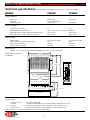
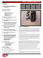
Model 7XX8 Digital Brushless Driver
FEATURES
•
MODEL
7228AC
7428AC
7228DC
7428DC
DSP controlled torque, velocity, or
position mode using encoder feedback
from the motor
•
Windows 98 software
•
Command sources:
VOLTAGE
32~132VAC
32~264VAC
45~186VDC
45~373VDC
I-PEAK
20
20
20
20
I-CONT
10
10
10
10
Analog +/-10V inputs
Digital PLS/DIR, CW/CCW
Digital Presets
Data RS-232, RS-485
•
•
•
•
•
•
•
•
Select up to 16 preset modes using a
PLC or Logic Hi/Lo line
Programmable S-curve and trapezoidal
motion profiles
RS-232 or RS-485 digital interface used
to store all settings in internal FLASH
memory for selecting preset modes
Separate motor signal and control
signal Sub-D type connectors for
simpler cabling
Terminals for DC Buss connect to
external regenerative energy dissipator
Input for motor temperature sensor
protects motor
No Transformer Required! AC Version
operates directly from AC mains, DC
Version operates from rectified line,
with full optical isolation between
signal and power stages.
32~132VAC ( 7228 )
32~264VAC ( 7428 )
Fault protections:
Short-circuits from output to
output, output to gnd
Over/under voltage
Over temperature
APPLICATIONS
PRODUCT DESCRIPTION
The 7XX8 series are DSP (Digital Signal Processor) controlled PWM servo
amplifiers from Copley Controls Corp. for control of AC brushless motors
that require sinusoidal commutation. 7XX8AC Models operate directly from
the AC mains while 7XX8DC Models operate form directly rectified line.
All models have full isolation between signal and power stages. No power
transformers are required.
All models take industry standard ±10V analog control signals for torque or
velocity control. In addition, stepper-motor command pulses in CW/CCW,
or PLS/DIR format, can be used for position control. External devices, such
as sensors or PLC connections, can initiate presets. Presets can include a
profiled move to a specific position, a change in tuning parameters, or a
complete change in operating mode. Through the 4 preset logic lines up to
16 distinct presets can be initiated.
Each driver will contain configuration information stored in nonvolatile
Flash Memory on the driver. Through the RS-232 port a single driver can be
configured for an unlimited number of axis in a system. The Copley Motion
Explorer software, a windows 95/98 visual basic interface, can be used to
tune, configure, and analyze the drive. The configuration data can be
uploaded and saved to disk for replicated usage. Consequently, the
modularity of the 7XX8 driver provides the user with a single spares
inventory that can be configured over all the needs of a system.
•
Linear Brushless Motors
•
Automated assembly machinery
Windows 95/98 & NT DLLs (Dynamic Link Libraries) work with virtually
all windows programing languages, including Visual C/C++, Visual Basic,
and others.
•
Packaging Equipment
A growing database of motor models and a continuously evolving collection
of amplifier operating modes are available as resources for the 7XX8 Driver.
1
Model 7XX8 Digital Brushless Driver
Technical specifications Test conditions: 25°C ambient, Load = 400
MODEL
H. in series with 1 Ohms.
7228AC
7428AC
20A @ 110V
1 second at peak power.
10A @ 130V
20A @ 205V
OUTPUT POWER
Peak power
Peak time
Continuous power
10A @ 250V
OUTPUT VOLTAGE
On-resistance (Ro, ohms)
Max PWM Peak Output Voltage
Maximum effective output voltage at continuous power
Maximum effective output voltage at peak power
0.2
0.15
±Vout = (VAC X 1.41 -2)X(0.97) - (Ro)X(Io)
130V @ 10A
250V @ 10A
110V @ 20A
205V @ 20A
INPUT POWER
Mains voltage
Mains current @ continuous output rating
Inrush current on startup
External mains fuse rating
32~132VAC, 47~63Hz
16A
37A max
20A/125V
32~264VAC, 47~63Hz
16A
37A max
20A/250V
MECHANICAL
Weight 3.71 lb (1.69 kg) without optional Heatsink. Add 3.2 lb ( 1.47 kg ) for heatsink.
7.50
(190.5)
MECHANICAL OUTLINE
AC MODEL
0.93 (23.62)
3.00
(76.2)
6.22
(158)
6.94
(176.3)
STATUS
Model: 7428AC
Input: 32~264VAC
50/60Hz
9
5
J4
DATA
J1
6
AC
H
1
N
2
37
1
19
3
BUSS
+
4
MOTOR
-
5
U
6
V
7
W
8
J3
SIGNAL
20
1
9
7.00
(177.8)
15
8
J2
MOTOR
9
1
9
15
20
37
6
Westwood, MA, USA
2.72
(69.1)
1.46
(37.08)
4.72 W/ Heat Sink Option
(119.9)
Heat Sink Option
CONNECTORS
J1: Power & motor
9-position terminal strip
J2: Motor
15-position female Sub-D type. #4-40 standoffs for cable shell lock screws
J3: Signal
37-position female Sub-D. #4-40 standoffs for cable shell lock screws
J4: RS-232/485
9-position female Sub-D. #4-40 standoffs for cable shell lock screws
Connector shells are connected to amplifier chassis for grounding/shielding
2
Model 7XX8 Digital Brushless Driver
MODEL
7228DC
7428DC
20A @ 180V
1 second at peak power.
10A @ 180V
20A @ 370V
OUTPUT POWER
Peak power
Peak time
Continuous power
10A @ 370V
OUTPUT VOLTAGE
On-resistance (Ro, ohms)
Max PWM Peak Output Voltage
0.2
0.15
±Vout = (VDC)X(0.97) - (Ro)X(Io)
INPUT POWER
Mains voltage
Mains current @ continuous output rating
Inrush current on startup
External mains fuse rating
45~186VDC
16A
19A max
20A/125V
45~373VDC
16A
37A max
20A/250V
MECHANICAL
Weight 2.71 lb (1.23 kg) without optional Heatsink. Add 3.2 lb ( 1.47 kg ) for heatsink.
MECHANICAL OUTLINE
DC MODEL
7.50
( 190.5 )
0.93
( 23.62 )
4.91
( 155.5 )
3.00
( 76.2 )
5.55
( 138.75 )
Model: 7428DC STATUS
Input: 45~373VDC
6
5
J4
1
9
DATA
J1
ENAB
POL
S1
J3
1
SIGNAL
13
25
BUSS
2
-
3
U
4
V
5
W
6
MOTOR
7.00
( 177.8 )
+
14
7
1
J2
MOTOR
15
2.00
1.00 ( 50.0 )
( 25.0 )
Heat Sink Option
9
Westwood, MA, USA
4.00 W/ Heat Sink Option
( 100.0 )
CONNECTORS
J1: Power & motor
7-position terminal strip
J2: Motor
15-position female Sub-D type. #4-40 standoffs for cable shell lock screws
J3: Signal
37-position female Sub-D. #4-40 standoffs for cable shell lock screws
J4: RS-232/485
9-position female Sub-D. #4-40 standoffs for cable shell lock screws
Connector shells are connected to amplifier chassis for grounding/shielding
3
8
1
Model 7XX8 Digital Brushless Driver
LOAD INDUCTANCE
Minimum inductance
Maximum inductance
400 H
No maximum. Bandwidth varies with inductance and supply.
BANDWIDTH
Small signal
-3dB @ 2kHz with minimum load at nominal supply voltage.
Varies with load inductance and PID filter values. 205uS rate.
PWM OUTPUTS
PWM frequency
Modulation
20kHz
Center-weighted, 50% duty cycle at 0V output
REFERENCE INPUTS
Torque or velocity
Position
Preset
Analog ±10V
Differential, 94k Ohms between inputs, ±20V maximum
Digital, 2-signal TTL, Any of three formats: CW / CCW; Pulse/Dir; A & B quadrature pulses.
Digital, 4 line
TTL, 28V max, Group programmable: 22k Ohms internal pull-up to +5V or
pull-down to 0V. The four inputs initiate 16 predefined modes.
ANALOG TACHOMETER INPUT
±120V or ±20V maximum, Jumper selectable. Load 240k Ohms
MOTOR OVERTEMP INPUT
Analog input
5k Ohms internal pull-up to +5V, for thermistor or IC sensor. Thresholds programable.
MOTOR ENCODER
INPUTS
A, B, X
2.2k Ohms internal pull-up to +5V.
differential or single ended, 4Meg. Counts/Sec maximum.
/Enc Buffout A
/Enc Buffout B
/Enc Buffout X
HCMOS, Differential line driver, Buffered encoder output A
HCMOS, Differential line driver, Buffered encoder output B
HCMOS, Differential line driver, Buffered encoder output X
BUFFERED OUTPUTS
HALL INPUTS
U, V, W, Single-ended, 10k Ohms internal pull-up to +5V
LOGIC INPUTS
Enable
Enables amplifier within 5ms when active.
Pos Enable
Enables CW rotation.
Neg Enable
Enables CCW rotation.
Reset
Resets latching fault condition, recovers in 1ms.
TTL, 28V max, Group programmable: 22k Ohms internal pull-up to +5V or put-down to 0V. Software programmable active Lo or Hi.
LOGIC OUTPUTS
Status output 1, 2
Software function programmable.
N-channel MOSFET, 10k Ohms pull-up to +5V, Max. 50V off-voltage,
Max. 250mA sink, 5 Ohms On-resistance. STATUS LED
Bicolor LED changes color and flashes to indicate amplifier operating status
Blinking green = Ready Amplifier OK, will run when enabled
Green
= Normal Amplifier enabled AND Amp OK (see above)
Red
= Buss Fault, non-latching Over or under-voltage condition. Amplifier recovers when in normal range
Blinking red
= Latching Fault, Output overcurrent (short circuit), following error, or overtemp condition.
Clear with software control, Ground /Reset, or power amp off/on to clear condition
ANALOG MONITOR
+/-10V Full scale, 1k Ohms source resistance . Programmable monitor functions.
DC POWER OUTPUTS
+5VDC @ 250mA, +12VDC @ 25mA, -12VDC @ 25mA
4
Model 7XX8 Digital Brushless Driver
DATA PORT
RS232 or RS485 jumper selectable. Permits programming parameters from PC. Settings held in flash memory.
RS232 3 wire (TxD, RxD, Gnd).
RS485 5 wire (XMT+, XMT-, RCV+, RCV-, Gnd) differential full duplex.
CONTROLLER GND
Floating. Gnd externally. Power stage optically isolated
THERMAL REQUIREMENTS
Storage temperature range -30°C to +85°C
Operating temperature range 0° to 70°C baseplate temperature
Thermal resistance (heatplate to ambient):
No heatsink or fan: 0.92 deg C/W, no heatsink with fan: 0.51 deg C/W
With heatsink: no fan: 0.6 deg C/W; with heatsink and fan: 0.23 deg C/W.
PROTECTION
Output to output short
Output to ground short
Overtemperature
Undervoltage
Overvoltage
Current-limiting
Latches unit OFF (will reset if /Reset input is wired to ground, or when power is cycled)
Latches unit OFF (will reset if /Reset input is wired to ground, or when power is cycled)
Latches unit OFF at 70°C on heatplate
(will reset if /Reset input is momentarily grounded, or when power is cycled off/on)
shutdown at internal DC buss < 45VDC
shutdown buss > 195VDC (7228) or buss > 390VDC (7428)
Output current peak, continuous, & peak-time limits programmed via RS232 port
CE CONFORMITY
EN 55011,1992
CISPR 11 (1990) Edition 2/ Amendment 2: Limits and Methods of Measurement of Radio
Disturbance Characteristics of Industrial, Scientific, and Medical (ISM) Radio Frequency Equip.
Electromagnetic Compatibility Generic Immunity Standard.
Safety Requirements for Electrical Equip. for Measurement, Control, and Lab Use.
EN 50082-1,1992
EN 61010-1,1993
Recommendations
A line filter, such as the Corcom P/N20VDK6, can be installed at least 3 feet from the driver’s power entry
terminal strip to reduce line noise. This will reduce the systems line noise for compliance with CE emissions
limits.
Power supply and motor connections should be made with wire that has a rating to support the amplifiers
continuous current. AWG 14 wire will support all amplifiers in this series. Additional recommendations for wire
insulation are for a voltage rating of 600V and a maximum temperature of 105°C
Fusing should be time delayed and install on any hot lines coming from the mains. The fusing for the high
voltage units should be rated for 250VDC at 25Amps and are to be installed on both hot lines. The fusing for the
low voltage units should be rated for 120VDC at 25 Amps and is to be installed on the hot line.
Signal Board Layout
Jumpers Settings
JP13
JP3 JP6JP4
A B
DSP
&
Internal
Flash RAM
8 7 6 5 4 3 2
LED
JP13
JP2
J4 Data Port
8
7
6
5
4
3 2
1
8 7
6
5
4
3
1
Factory installed
Do not move
RS-232 (Default)
JP1 JP3
RS-485
JP1
1
J3 Signal
Function
J2 Encoder/Hall
5
2
JP2
Tach. Scale (Default)
Range +/-20Vmax.
JP2
Tach. Scale
Range +/-120Vmax.
A
B
Force
9600
Baud
JP6 JP4
Model 7XX8 Digital Brushless Driver
Software installation
To install the Copley software load the CD and run setup.exe, after the Copley software is installed the
Copley icon will appear on the Windows Program file list. To run the Copley software, double-click on the
Copley icon.
Splash screen
When the Copley Motion Explorer software is
initiated, the splash screen will appear, See Fig 1.
Press the On-Line button to work live. If a new
motor is being used and no amplifier or motor file
is available, then the motor data file can be
created off line by pressing OFF-Line and using
the motor data form.
Fig. 1: Splash screen: Click On-line if the amplfiier is connected.
Communication Form
The Communication form will appear on screen
after loading, See Fig 2. Press the COMM
button for the proper serial port. Press the
Connect button to connect to the driver. Verify
the amplifier data that is indicated on the screen,
then press the Continue button. If
communication is lost then press Amplifier /
Connect to Host to load the communication
form.
Before the Copley software can communicate
with the 7XX8 amplifier, the RS-232 or RS-458
port must be connected. If communication is
successful then the amplifier found indicator on
this form will be illuminated green.
The bar graph indicates that the presets are
uploading from the driver to the computer.
Fig. 2: Communication form: Connect and upload data.
Software and firmware updates
As time progresses into the future, new features and enhancements will be added to the Copley Motion
explorer software and DSP firmware. Typically a new release will contain a software and a firmware update.
The firmware can be updated through the Copley Motion Explorer by selecting Tools \ Download firmware
then select the appropriate cplyXXXX.bin filename, containing the latest firmware to download. The
Download form will display Erasing and then the downloading bargraph. The firmware version can be
verified on the communication form after re-establishing communication.
6
Model 7XX8 Digital Brushless Driver
Drive status
The Amplifier Status Now! form presents the latest status data retrieved from the driver, See Fig 3. The
Status Updates check-box, located under the communication button, can be checked to continuously retrieve
fresh data. The driver’s current preset, operating mode, and other critical data are indicated. These settings
can be modified by pressing the More button. When all indicators are illuminated green the drive is enabled
and running. If an in indicator is illuminated red then a fault condition has occurred. Press the Amp OK
button to diagnose and correct the fault.
Fig. 3: Status Now form with “More” values for current preset displayed.
Applying changes & saving presets to the amplifier
Changes to the displayed settings are highlighted in yellow. These changes can be immediately applied to
the amplifier by pressing the Apply Now button. The displayed settings can be downloaded to a preset for
later execution by pressing the Save as Preset button and selecting the desired preset number. Use the Void
Preset to terminate the values in an amplifier preset. Use the Load Preset button to view a preset from the
amplifier.
7
Model 7XX8 Digital Brushless Driver
First Move
To make a move the amplifier must be configured for the motor. Typically the demo kit is factory configured
for position mode. Refer to the kit application note to verify all preset values. Example: If the application
note says “Operating mode is POS>TORQUE”, then verify that this is true. If values are not correct then
make changes as appropriate, apply, and save to the desired preset. Some important values are the P and I
values for the current loop tuning, if the current loop gain is too low then poor operation and motor
overheating may occur, if too high then oscillations may occur.
Enable the drive
To enable the amplifier, switch the Enable line low with the hardware, or
check the Enable = +5V box, to change the active level of the enable line, See
Fig 4. Apply change, but do not save this change to a preset unless necessary.
In this default fail safe mode, if the line is cut then the amplifier is disabled.
(Enable the drive at this time and verify that the green LED, on the drive, is
on.) Refer to the Kit application note for details of factory configured Presets
Fig. 4: Enable polarities
and there function.
Motion Profiles
The Profile Mode can be trapezoidal, S-curve, velocity, or gearing. If a
sinusoidal S-curve profile is chosen then a value Jerk must be set. The
velocity profile is actually a position loop that never gets to the destination.
If no value for deceleration is entered than the acceleration value will be
used, See Fig 5.
After a move the position count will settle in the settle window, then after the
settle time, the settled status will change.
Position loop
Fig. 5: Motion Profile values
The position loop tuning parameters are determined by a math model and
are initialized “Soft” and with out loading of the motor. For proper
operation with a load, the PID values for the Position Loop may need to be
changed, See Fig 6.
A method for tuning:
1. Adjust the integral Limit to 0 or set the integration term “I” to 0.
2. Increase the derivative term “D” for a sufficiently low position error.
3. Increase the proportional gain “P” for a sufficiently stiff position loop.
4. Increase the integration limit and integration term “I” for sufficient
holding torque under load.
The position error limit is the number of encoder counts allowed before a
position error occurs.
Kout is a multiplier at the end of the digital position loop so, must not be
set to zero.
Refer to Users Guide for more details on other position loop values.
8
Fig. 6: Position loop values
Model 7XX8 Digital Brushless Driver
Trace
The Trace form can be used to display
measured signals and events. Located on
the toolbar at Tools\Trace.
Example: The Position Error trace can be
displayed by selecting the appropriate item
in the Trace Var pull-down menu and
commanding the motor to a new position,
See Fig 7. The trace can be initiated upon
updating the driver with new instruction by
selecting the Update option in the
condition options. The trace display can be
armed for capturing a trace by pressing the
Arm button. For continuous arming on a
condition check the Auto Arm box. Fig. 7: Trace of trapezoidal motion profile with position error of 10 counts.
Temperature Sensor
If no temperature sensor is used then do not check
the Temp Sensor box. If a temperature sensor is
used then the operation thresholds can be set using
the Temp Sensor form, See Fig 8. Press he temp
Sensor button to view the form.
Fig. 8: Temperature sensor input form
Status Output
The status output Stat-0 and Stat-1 can be programed to indicate
that a fault condition has occurred or a motion profile is active. Press
the Status Output button located on the Status Now\More form to
open the Status Output form, See Fig 9. Check the appropriate
status box, True/False button, and On Hi/On Low option.
End of Move
The Status line can be used to indicate the end of a move. This is
useful for a PLC that is monitoring a line for the end of move
indicator, before initiating another preset move.
Saving an Amplifier Configuration
Fig. 9: Status form truth table
During initial communication with the amplifier, all the presets are uploaded to the computer. If the
amplifier has not been pre-configured then all the presets will be void. If the Copley amplifier has been preconfigured to operate with a particular motor then some or all of the presets will be configured. These
presets can be viewed with the Preset Manager. An amplifier configuration can be saved to a .cca file, use
the File\Save As form to save the file with an appropriate name, such as Demo343GR-001.cca.
9
Model 7XX8 Digital Brushless Driver
Using a new motor
Downloading an Amplifier Configuration
To open the .cca file containing a previously configured amplifier data, use the File\Open form to locate and
open a file. Existing motor and amplifier files are available on disk or through the Internet.
Motor data file
To create a new .ccm motor file, use the Motor
\ Motor Data form to enter the motor’s type,
feedback, electrical, and mechanical data, See
Fig 10A. When all the data has been entered
press the Save button to save the file with an
appropriate name.ccm. After the motor data
form has been filled press the Calculate Amp
Data button. This will generate initial tuning
parameters form a mathematical model for
initial testing.
Fig. 10A: Motor data used for initial tuning calculations.
Press the Apply to Amp button to apply the calculated initial tuning values to the Status Now form.
Motor Data
After the motor data is loaded, whether from an amplifier file or from a model
calculation, verify that the values are correct, See Fig 11A.
The current limit source can be external, where a voltage or resistance is used to
set the peak current limit, or internal where the continuous current limit and peak
current limit values are used.
The average voltage can be limited to the motor by setting the PWM limit %.
An important value to get correct is the Phase counts, the number of encoder
counts per electrical cycle.
If the motor has Halls then Trapezoidal or Sinusoidal commutation, and Hallbased or Algorithmic phasing can be used. If no Halls are present, then use
algorithmic phasing mode with Phase correction mode ON, Phase initialization
time set, and sinusoidal commutation.
Encoder polarity, normally low pulse high index “_-_”or normally high pulse low
index “-_-”, must be set correctly for proper algorithmic phasing or phase
correction. Also, the timing of the index pulse, with respect to the state of the
Fig. 11A: Motor data
A+B pulses, must be selected correctly for proper detection of the index pulse.
values
First time phasing
If a motor has been previously phased for commutation with a Copley amplifier then the same wiring of the
Halls and motor phases will apply. Otherwise use the Auto Phasing routine for proper phasing of a new
motor. This screen is located under Diagnostics>Specail>More>Auto Phase. See Fig. 11B. Prior to
phasing the amplifier must have values set, either from an amplifier file or model calculation. Torque mode
with 0% command is good and +-3% command can be used after phasing to test.
10
Model 7XX8 Digital Brushless Driver
Auto phasing
The Auto phasing screen can be used to
phase the motor Halls, encoder, and UVW
power wires. Check the Auto update box to
read the present Hall state. If the motor is
rotated through 1 electrical cycle then all 6
Hall states can be viewed, if the motor
Halls are phased correctly then the Hall
angle Green LED will make 1 congruent
rotation. Press Attempt Phasing to initiate
the routine. The default motor command
will be 10% of continuous current setting,
the phase init time will be in the range of 1
to 10 seconds, and the phase counts settings
will be used. If all goes well then the
Fig. 11B: Adjustments to initial tuning calculations.
Output Angle will track the Hall angle,
and any Hall offset detected will be
indicated.
Intuitive Tuning Slides
After the model calculates the initial tuning parameters, the slides can be used to adjust the model
parameters, much like a mechanical engineer would understand the system. See Fig 11C. The slides make
intuitive tuning adjustments possible with the motor and load connected in a system.
Current Loop Slides
The Bandwidth slide can be used to
increase or decrease the current loop
response. If proper values of motor
inductance and resistance are entered for
the calculations then the default current
loop response is typically > 1kHz. The
Peaking slide can be used to effect the
amount of overshoot of the current loop
response. Typical peaking is about 5%. The
default current loop values calculated by
the model are excellent so, it is unnecessary
to change them.
Fig. 11C: Adjustments to initial tuning calculations.
Position Loop Slides
The Bandwidth slide can be used to change the system bandwidth, effecting the PID values, “I” Term and
“D” term mostly. The Gain slide changes the overall system gain by effecting the Kout term. The stiffness
slide changes the system stiffness by effecting the “P” term. The Kaff slide changes the acceleration feed
forward by effecting the Kaff term, this is used to reduce position error during acceleration. The Kvff slide
changes the velocity feed forward by effecting the Kvff term, this is used to reduce position error during
velocity.
11
Model 7XX8 Digital Brushless Driver
Operating Mode Briefs
At the time of this printing there are several operating modes available, such as position mode, velocity mode,
stepper mode, and torque mode. Future releases will make more modes of operation available.
Position mode
By selecting Pos>Torque, from the Operating mode pull down list, the drive can be configured for a
position loop driving a current loop. The current loop gains and limits apply to the torque loop that operates
inside the position loop. With the position loop selected the motion profile and position loop values are
applicable.
Velocity mode
The velocity loop operates as a position loop that never reaches the destination position. By selecting
Pos>Torque, from the Operating mode pull down list and then selecting velocity from the profile mode pull
down list, the drive can be configured for a velocity loop in a position loop driving a current loop. The
current loop gains and limits apply to the torque loop that operates inside the position loop. With the
velocity loop selected, some of the motion profile and all of the position loop values are applicable.
By selecting +/-10V>Pos>Torque, from the Operating mode pull down list and then selecting velocity from
the profile mode pull down list, the drive can be configured for a velocity loop, in a position loop, driving a
current loop, that uses the external +/-10V reference to command velocity. The current loop gains and limits
apply to the torque loop. With the velocity loop selected, some of the motion profile and all of the position
loop values are applicable.
Torque mode
By selecting Torque, from the Operating mode pull down list, the drive can be configured for a torque (or
current) loop. The current loop gains and limits apply to the torque loop. With the torque loop selected the
Command % and Current loop values are applicable. The motion profile and position loop values are not
applicable.
By selecting +/-10>Torque, from the Operating mode pull down list, the drive can be configured for a
torque (or current) loop that uses the external +/-10V reference to command current. The current loop gains
and limits apply to the torque loop. With the +/-10V>torque loop selected the Current loop values are
applicable. The command %, motion profile, and position loop values are not applicable.
Digital position mode
By selecting Pos>Torque, from the Operating mode pull down list and then selecting Gear, from the profile
mode pull down list, the drive can be configured for a Digital position loop driving a current loop. The
current loop gains and limits apply to the torque loop that operates inside the digital position loop. With the
gear profile mode selected, some of the motion profile and all of the position loop values are applicable.
The digital input source can be set to any one of the below listed modes:
A/B Encode, Where quadrature encoder pulses are used as a master encoder to position the motor.
CW / CCW, Where pulses on the clock wise line produce CW rotation and pulses on the counter clockwise
line produces CCW rotation.
Pls / Dir, Where stepper pulse and direction are used to position the motor.
Gear Ratio
The gear ratio can be set to scale the number of digital input counts to the number of encoder counts.
12
Model 7XX8 Digital Brushless Driver
Amplifier Connections
Functional Diagram AC Model
Command Inputs
Ch. A
Pulse
Ch. /A
Direction
Ch. B
Pulse CW
Pulse CCW
Ch. /B
A Quadrature
Ch. X
B Quadrature
Ch. /X
Ref(+)
+/-10V Anolog
Ref(-)
Shld
Signal ground
J3
35
18
36
Inputs
Enc A out
Enc /A out
Enc B out
Enc /B out
Enc X out
Enc /X out
Shld
37
2
1
/Preset-2
6
/Preset-3
25
/Reset
23
26
3
/Pos enable
21
/Neg enable
22
J3
Outputs
Analog monitor
Status-0
Status-1
9
7
Hall U
Hall V
3
8
DSP
&
FLASH RAM
Encoder
Receiver
&
Home
pulse
logic
15
7
14
6
13
Encoder
buffer
+5V
Power
11
12
1
Sensor
ADC
Preset
input
logic
Active
state Prog.
9
12
Halls
Hall W
Enc A
Enc /A
Enc B
Encoder
Enc /B
Enc X
Enc /X
+5V
0V
Shld
Motor Overtemp
Switch
/Motemp
Gnd
J1
PWM
Stage
"H"
Bridge
&
Current
Sense
Group Prog.
Pull-up/down
Enable
input
logic
Internal
DC
supply
&
Inrush
limiter
Monitor
DAC
Status
FETS
8
Gnd
5
4
Active state
Prog.
4
/Home
Hall
Receiver
Group Prog.
Pull-up/down
24
3
2
11
/Preset-1
RS-232
Data Port
Rx
J2
Mode Selects
12
30
13
31
14
32
1
Tx
2
Jumper Selects
Mode Selects
20
5
/Enable
Pulse and
Direction
Format
Logic
Dif Amp
&
ADC
/Preset-0
Signal Gnd
RS-232
OR
RS-485
Driver/
Receiver
19
Note:
Amplifier signal ground must be
connected to controller ground.J3
Buffered
Buffered
Buffered
Buffered
Buffered
Buffered
J4
17
6
U
7
V
Motor
8 W
9
Shld
1
L1 time-delay Blk (Brn)
2
L2 Wht (Blu)
Fuse: 20A
3
Grn
L1
L2
Signal Gnd34
Note: Circuits within dashed line are
HOT! (At mains potential)
13
115VAC
Wiring for
7228AC
Fuses: 20A
Blk (Brn)
time-delay
Grn (Grn/
Yel)
230VAC
Wiring for
7428AC
Model 7XX8 Digital Brushless Driver
J1 Connections
AC Model
J1
J1
6
Motor U
7
Motor V
3
8
Motor W
4
9
1
2
PIN
SIGNAL
Function
1
L1
AC Power Input Hot (black or brown wire from AC mains)
2
L2
AC Power Input Neutral (white or blue wire from AC mains)
3
GND
4
Buss (+)
Positive terminal of internal DC power supply (N.C.)
5
Buss (-)
Negative terminal of internal DC power supply (N.C.)
6
Motor U
Amplifier output to “U” winding of motor
7
Motor V
Amplifier output to “V” winding of motor
8
Motor W
Amplifier output to “W” winding of motor
9
GND
Chassis safety ground (green or green/yel wire from AC mains)
Chassis safety ground. Also for cable shield of motor cable.
< 3ft
5
L1
1
6
L2
2
7
Fuses: 25A
time-delayBlk (Brn)
Line Filter
Wht (Blu)
c Corcom
3
8
Grn (Grn/Yel)
9
4
Buss +
5
Buss -
Fuses: 25A
time-delay
Note: All lines in this
power stage are HOT!
(At mains potential)
Copley Driver
1
GND
2
Buss (+)
DC power input positive terminal from DC power supply
3
Buss (-)
DC power input negative terminal from DC power supply
4
Motor U
Amplifier output to “U” winding of motor
5
5
Motor V
Amplifier output to “V” winding of motor
6
6
Motor W
Amplifier output to “W” winding of motor
7
GND
4
2
3
7
4
Buss+
Function
Chassis safety ground (green or green/yel wire from AC mains)
Chassis safety ground. Also for cable shield of motor cable.
Inrush limiter
2
5
Fuses
time-delay
NTC
6
3
7
230VAC
Wiring for 74XX
SIGNAL
J1
1
Blk (Brn)
PIN
DC Model
J1
Grn (Grn/Yel)
120VAC
Buss -
Wht (Blu)
Grn (Grn/Yel)
1
120VAC
Wiring for 72XXD
Copley Driver
Buss+
Note: All lines in this
power stage are HOT!
(At mains potential)
Blk (Brn)
Fuses
time-delay
DC
Buss- Power
Supply
Grn (Grn/Yel)
Blk (Brn)
230VAC
Wiring for 74XX
14
Model 7XX8 Digital Brushless Driver
LED Indicator functions
Color and state of LED indicates amplifier operating conditions:
COLOR
CONDITION
ACTION REQUIRED TO ENABLE
Flashing Green
Ready
Enable amplifier (J3-3) (Note 1)
Green
Normal
None. Normal “RUN” condition.
Red
Power Fault
Flashing Red
Latching Fault
Bring AC voltage into range.
Ground /Reset input, or cycle AC power OFF/ON
Signal Wiring
Signal connections should be made with wire that has a rating to support the signal current. AWG 24 wire will
support all motor signals in this series. Additional recommendations for wire insulation are for a voltage rating
of 300V and a temperature range of 80°C. To minimize coupling of PWM noise, sensor signal wiring should be
multiple-conductor twisted-pair shielded cable. Further more, all cable shields should be case grounded at both
ends for compliance with CE emissions limits.
J2 Motor Hall and Encoder Signal Connections
PIN
SIGNAL
1
Safety GND
2
Hall U
Digital Hall inputs for “U”
3
Hall V
Digital Hall inputs for “V”
4
Hall W
Digital Hall inputs for “W”
5
Analog Tach
6
Enc Ch. X
Encoder Channel X
7
Enc Ch. B
Encoder Channel B
8
Enc Ch. A
Encoder Channel A
9
Motemp
10
N.C.
11
Function
Chassis ground. Not connected to internal signal ground.
Brush tachometer input
Motor teperature sensor
No connection
+5V @ 250mA. DC power for encoders and Halls (Note 1)
12
0V.
Signal ground for +5V and Halls.
13
Enc Ch. /X
Encoder Channel /X
14
Enc Ch. /B
Encoder Channel /B
15
Enc Ch. /A
Encoder Channel /A
Notes:+5VDC @ 250mA connects to J3-15, J3-27 and J2-11. Combined not to exceed 250mA.
15
Model 7XX8 Digital Brushless Driver
User & Control Signals Connections
J3 Signal Connections
PIN
SIGNAL
Function
PIN
SIGNAL
Function
1
Safety GND
Chassis/frame ground.
2
Ref (+)
+/-10V analog command input
20
Ref (-)
+/-10V analog command input
3
/Enable input
Amplifier enable
21
/Pos Enable
Positive direction enable
4
/Home
Home switch input
22
/Neg Enable
Negative direction enable
5
/Preset-0
1 of 4 preset mode select lines
23
/Reset
Amplifier fault reset input
6
/Preset-2
1 of 4 preset mode select lines
24
/Preset-1
1 of 4 preset mode select lines
7
Status-0 Out
Amplifier status output #1
25
/Preset-3
1 of 4 preset mode select lines
8
Status-1 Out
Amplifier status output #2
26
0V Sgnd
Signal Ground
9
Analog Mon
Programmable monitor output
27
+5V Output
+5VDC @ 250mA output
10
Curr Limit
External current-limit input
28
+12V Output +12VDC @ 25mA output
11
0V Sgnd
Signal Ground
29
-12V Output -12VDC @ 25mA output
12
Ch. A out
Buffered encoder output Ch A
30
Ch. /A out
Buffered encoder output Ch /A
13
Ch. B out
Buffered encoder output Ch B
31 Ch. /B out
Buffered encoder output Ch /B
14
Ch. X out
Buffered encoder output Ch X
32
Ch. /X out
Buffered encoder output Ch /X
15
+5V Output
+5VDC @ 250mA
33
Ch. A
Encoder input Chan. A
16
N.C.
No connection
34
0V Sig Gnd. Signal Ground
17
Ch. A in
Encoder input Chan. A
35
Ch. /A in
Encoder input Chan. /A
18
Ch. B in
Encoder input Chan. B
36
Ch. /B in
Encoder input Chan. /B
19
Ch. X in
Encoder input Chan. X
37
Ch. /X in
Encoder input Chan. /X
J4: Communications/Data Connections
7xx8 models support RS-232 and RS-485. Jumpers on the signal PC board set the configuration for either type
of communication protocol. Data connections should be made with wire that has a rating to support the signal
current. AWG 24 wire will support all data signals in this series. Ribbon cable is acceptable for short distances
and baud rates less than 9600 however, to minimize coupling of PWM noise, data signal wiring should be
multiple-conductor twisted-pair shielded cable. The amplifier looks like DCE (Data Communications Equipment) and does not require a “null-modem” cable.
RS-232 Connection
PIN
SIGNAL
Function
1
-
2
TxD
RS-232 Serial Data Output (Amp —> Controller)
3
RxD
RS-232 Serial Data Input (Controller —> Amp)
4
-
5
Gnd
-
Ground
16
Model 7XX8 Digital Brushless Driver
18'' Flying lead
CBL162BE-001 Motor Performa
Buss = 75VDC, Ic = 4A, Ip = 20A
Torque (oz-in)
240
200
160
120
80
40
0
Peak
Continuous
1k
2k
3k
4k
5k
6k
Speed (rpm)
25C Ambient w/ Heat sink
4.79
CBL232BE-001 Motor Performan
4X O 0.218
thru holes equ. spaced
on O 2.625 bolt circle
Torque (oz-in)
Buss = 160VDC, Ic = 4.1A, Ip = 20A
480
400
320
240
160
80
0
0.81
18"Flying Leads
0.75
+0.0000
O 0.3750 -0.0005
Peak
Continuous
1k
2k
3k
O 1.500
+/-0.001
2.25
4k
5k
6k
Speed (rpm)
25C Ambient w/ Heat sink
232 = 4.98
233 = 5.98
1.856
CBL232AE-001 Motor Performance
600
500
400
300
200
100
0
Peak
Continuous
1k
2k
3k
4k
Speed (rpm)
5k
Buss = 160VDC, Ic = 4.1A, Ip = 20A
Peak
Torque (oz-in)
Torque (oz-in)
600
500
400
300
200
100
0
CBL233BE-001 Motor Performa
Buss = 250VDC, Ic = 2.1A, Ip = 10.5A
Buss = 160VDC, Ic = 2.1A, Ip = 10.5A
Continuous
1k
2k
3k
4k
5k
Speed (rpm)
690
560
448
336
224
112
0
Peak
Continuous
1k
2k
3k
Speed (rpm)
1k
2k
3k
4k
5k
6k
Speed (rpm)
25C Ambient w/ Heat sink
Torque (oz-in)
6k
Peak
Continuous
1k
2k
3k
4k
5k
6k
25C Ambient w/ Heat sink
0.500
1.190
0.063
Continuous
O 2.875
5k
300
250
200
150
100
50
0
0.125
Peak
4k
5k
Speed (rpm)
Buss = 160VDC, Ic = 5.8A, Ip = 15.4A
3k
4k
Buss = 160VDC, Ic = 4.1A, Ip = 12.4A
Continuous
0.56
2k
3k
CBL341FE-001 Motor Performan
Peak
CBL343GE-001 Motor Performan
1k
2k
Buss = 250VDC, Ic = 2.1A, Ip = 10.5A
840
700
560
420
280
140
0
25C Ambient w/ Heat sink
900
750
600
450
300
150
0
1k
25C Ambient w/ Heat sink
Torque (oz-in)
Torque (oz-in)
Buss = 160VDC, Ic = 2.1A, Ip = 10.5A
Continuous
Speed (rpm)
CBL233AE-001 Motor Performance
840
700
560
420
280
140
0
Peak
6k
Speed (rpm)
25C Ambient w/ Heat sink
3.25
17
+ 0.002
- 0.002
O
0.5000
4X O 0.223 Thru Hole
On O 3.875 Bolt Circle
For #10 Bolt
3.26
+ 0.002
- 0.002
0.250
341F = 4.94
343G = 6.94
Model 7XX8 Digital Brushless Driver
Amplifier Ordering Guide
Amplifier Features
Notes:
7228AC
20A peak, 10A continuouse, from 32~132VAC, 50/60Hz AC mains
7428AC
20A peak, 10A continuouse, from 32~264VAC, 50/60Hz AC mains
7228DC
20A peak, 10A continuouse, from 45~186VDC, (32~132VAC rectified)
7428DC
20A peak, 10A continuouse, from 45~373VDC, (32~264VAC rectified)
1. Add “H” to model number to specify heatsink option.
2. Add “F” to model number to specify filter option. Example: 7228ACFH
Value Package Ordering Guide
Motor
Amplifier Connections Torque
Speed
NEMA SHAFT
CBL-162BE-001 7228AC
18" Flying Leads
44 oz-in continuous stall, 220 oz-in peak
6000rpm
Size 16
1/4" round
CBL-232AE-001 7428AC
18" Flying Leads 92 oz-in continuous stall, 460 oz-in peak
4500rpm
Size 23
3/8" round
CBL-232BE-001 7228AC
18" Flying Leads 98 oz-in continuous stall, 477 oz-in peak
6000rpm
Size 23
3/8" round
CBL-233AE-001 7428AC
18" Flying Leads 144 oz-in continuous stall, 700 oz-in peak
2800rpm
Size 23
3/8" round
CBL-233BE-001 7228AC
18" Flying Leads 140 oz-in continuous stall, 685 oz-in peak
6000rpm
Size 23
3/8" round
CBL-341FE-001
7228AC
Millitary Style
102 oz-in continuous stall, 307 oz-in peak
6000rpm
Size 34
1/2" keyway
CBL-343GE-001 7228AC
Millitary Style
288 oz-in continuous stall, 864 oz-in peak
4050rpm
Size 34
1/2" keyway
Notes:
1. Value packages do not include accessories, see development kits for a complete set of all accessories.
Accessories Ordering Guide
Accessories Features
Control Pendant
Hand controler with switches, potentiometers, and connections for testing
Software CD
CD rom with Copley Motion Explorer TM Software
Users Guide
Printed Users Manual for the 7XX8 Digital Amplifier Series
Cables
Connections
Feet Features
34MS-10
Military Style
10Ft
Twisted shielded cables for motor power and signal
23FL-6
Amp
6ft
Twisted shielded cable for size 23 & 16 motor power
120VAC Line
Plug
6ft
18 AWG USA power cord.
Data Cable
9pin D-Sub
6ft
Twisted shielded cable for RS-232 communication
Pendant Extention
37pin D-Sub
6ft
Twisted shielded cable for control pendant
Motor Signal Extention
15pin D-Sub
6ft
Twisted shielded cable for size 23 & 16 motor signal
18
Model 7XX8 Digital Brushless Driver
Connection Diagram
The diagram below can be used for quick connection of a development kit. If alternative components are used, such as a user supplied
motor, consult the users guide for connection details, using a new motor, and first time phasing instructions.
Driver
Model: 7428AC
Input: 32~264VAC
PC or Laptop
STATUS
50/60Hz
Fuse
120VAC Line Cord
Black
J1
1
N
2
Green
5
J4
DATA
H
AC
White
RS-232 Cable
9
3
6
37
1
19
Pendant Signal Cable
4
U
6
V
7
W
8 20
BUSS MOTOR
+
-
5
J3
SIGNAL
1
9
15
Encoder/Hall cable
8
J2
19
1
MOTOR
9
37
1
20
7xx8 Pendant
SGND
A
/A
+5V
GND
B
/B
X
/X
Aux
Encoder
Input
Motor Power Cable
Refer to the application note for
connection details for this kit.
+5V
0V
SGND
STAT-1 STAT-0
STATUS
RESET
+5V
GND
HOM NEG
POS
AMP
ENABLES
Brushless Motor
Analog
Monitor
+5V
GND
Gnd
1
0
2
3
PRESETS
100%
100%
FWD
OPEN
REV
0%
0%
CURRENT
LIMIT
+/-10V
Control Pendant
Development Kit Ordering Guide
Kit
Amplifier Motor
Stall Torque Peak Torque Speed
NEMA
SHAFT
Kit-001
7228AC
CBL-162BE-001
44 oz-in
220 oz-in
6000rpm
Size 16
1/4" round
Kit-002
7428AC
CBL-232AE-001
92 oz-in
460 oz-in
4500rpm
Size 23
3/8" round
Kit-003
7228AC
CBL-232BE-001
98 oz-in
477 oz-in
6000rpm
Size 23
3/8" round
Kit-004
7428AC
CBL-233AE-001
144 oz-in
700 oz-in
2800rpm
Size 23
3/8" round
Kit-005
7228AC
CBL-233BE-001
140 oz-in
685 oz-in
6000rpm
Size 23
3/8" round
Kit-006
7228AC
CBL-341FE-001
102 oz-in
307 oz-in
6000rpm
Size 34
1/2" keyway
Kit-007
7228AC
CBL-343GE-001
288 oz-in
864 oz-in
4050rpm
Size 34
1/2" keyway
Notes:
1.Kit Includes: Power cord, Data cable, Motor signal cable, Motor power cable,
Connector Kit, Pendant cable, Pendant, Software CD, Users Manual.
2. Size 16 & 23 motors have flying leads with connector. Size 34 motors have military style connectors.
Rev B 01/1/
Corporate Offices: 20 Dan Road
Canton, MA 02021
19
Telephone: (781) 282-8090
Fax: (781) 828-1750
www.copleycontrols.com