1
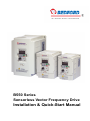
B550 Series
Sensorless Vector Frequency Drive
Installation & Quick-Start Manual
B550 Series sensorless vector frequency drive
Preface
Thank you for choosing B550 series sensorless vector frequency Drive. B550 series
are manufactured by adopting high-quality components, material and incorporating the
latest microprocessor technology available.
Getting Started
This manual will be helpful in the installation, parameter setting, troubleshooting, and daily
maintenance of the AC motor drives. To guarantee safe operation of the equipment, read
the following safety guidelines before connecting power to the AC motor drives.
Keep
this operating manual handy and distribute to all users for reference.
!
WARNING
!
Always read this manual thoroughly before using B550 series AC Motor Drives.
!
DANGER! AC input power must be disconnected before any maintenance. Do not
connect or disconnect wires and connectors while power is applied to the circuit.
Maintenance must be performed by qualified technicians.
!
CAUTION! There are highly sensitive MOS components on the printed circuit boards.
These components are especially sensitive to static electricity. To avoid damage to
these components, do not touch these components or the circuit boards with metal
objects or your bare hands.
!
DANGER! A charge may still remain in the DC-link capacitor with hazardous voltages
even if the power has been turned off. To avoid personal injury, please ensure that
power has turned off before operating AC drive and wait ten minutes for capacitors to
discharge to safe voltage levels.
!
CAUTION! Ground the B550 series using the ground terminal. The grounding
method must comply with the laws of the country where the AC drive is to be installed.
refer to Basic Wiring Diagram.
!
CAUTION! The final enclosures of the AC drive must comply with EN50178. (Live parts
shall be arranged in enclosures or located behind barriers that meet at least the
requirements of the Protective Type IP20. The top surface of the enclosures or barrier
that is easily accessible shall meet at least the requirements of the Protective Type
IP20). (Users must provide this environment for B550 series.)
!
DANGER! The AC drive may be destroyed beyond repair if incorrect cables are
connected to the input/output terminals. Never connect the AC drive output terminals
U/T1, V/T2, and W/T3 directly to the AC main circuit power supply.
B550 Series sensorless vector frequency drive
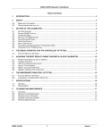
TABLE OF CONTENTS
CHAPTER 1 RECEIVING AND INSPECTIONS
1.1 Nameplate Information ...................................................................... 1-1
1.2 Model Explanation ............................................................................. 1-1
1.3 Serial Number Explanation ................................................................ 1-1
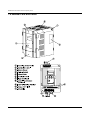
1.4 External Parts and Labels.................................................................. 1-2
CHAPTER 2 STORAGE AND INSTALLATION
2.1 Storage .............................................................................................. 2-1
2.2 Ambient Conditions............................................................................ 2-1
2.3 Installation ........................................................................................ 2-2
CHAPTER 3 WIRING
3.1 Basic Wiring Diagram ........................................................................ 3-2
3.2 External Wiring................................................................................... 3-3
3.3 Control Terminal Wiring ..................................................................... 3-4
3.4 Main Circuit Wiring............................................................................. 3-7
3.5 Wiring Notes ...................................................................................... 3-8
3.6 Motor Operation Precautions............................................................. 3-9
CHAPTER 4 DIGITAL KEYPAD OPERATION
4.1 Description of Digital Keypad ............................................................ 4-1
4.2 Explanation of LED Indicators ........................................................... 4-2
4.3 Explanation of Displayed Messages.................................................. 4-3
4.4 Keypad Operation .............................................................................. 4-4
CHAPTER 5
DESCRIPTION OF PARAMETER SETTINGS...................... 5-1
CHAPTER 6 MAINTENANCE AND INSPECTIONS
6.1 Periodic Inspection ............................................................................ 6-1
6.2 Periodic Maintenance ........................................................................ 6-1
CHAPTER 7
TROUBLESHOOTING AND FAULT INFORMATION .......... 7-1
CHAPTER 8
SUMMARY OF PARAMETER SETTING .............................. 8-1
APPENDIX A STANDARD SPECIFICATIONS .......................................... A-1
B550 Series sensorless vector frequency drive
This page intentionally left blank.
B550 Series sensorless vector frequency drive
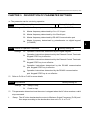
CHAPTER 1 RECEIVING AND INSPECTION
This B550 series AC drive has gone through rigorous quality control tests at the factory
before shipment. After receiving the AC motor drive, please check for the following:
Receiving
9 Check to make sure that the package includes an AC drive, the User Manual, and
rubber bushings.
9 Inspect the unit to insure it was not damaged during shipment.
9 Make sure that the part number indicated on the nameplate corresponds with the part
number of your order.
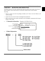
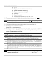
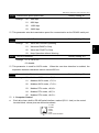
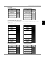
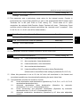
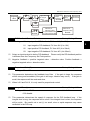
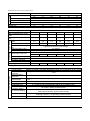
1.1 Nameplate Information: Example of 1HP 230V AC drive
AC Dr ive Model
Input Spec.
Output Spec.
Output F requenc y Range
Bar C ode
Seri al Number
Softwar e Vers ion
MODE
: B 5 5 0 - 2001
INPUT
: 3P H 200 -2 40V 50/6 0Hz 6.0A
OUTPUT : 3P H 0-240 V 5. 0A 1. 9kVA 1HP
Freq. Ra nge :0. 1~4 00Hz
007 M23A0 T0 0112 30
Manufacturer:
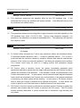
1.2 Model Explanation
1-1
B550 Series sensorless vector frequency drive
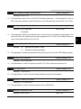
1.4 External Parts and Labels
1-2
B550 Series sensorless vector frequency drive
CHAPTER 2 STORAGE AND INSTALLATION
2.1 Storage
The AC drive should be kept in the shipping carton before installation. In order to retain the
warranty coverage, the AC drive should be stored properly when it is not to be used for an
extended period of time. Some storage suggestions are:
Store in a clean and dry location free from direct sunlight or corrosive fumes.
Store within an ambient temperature range of -20 °C to +60 °C.
Store within a relative humidity range of 0% to 90% and non-condensing environment.
Store within an air pressure range of 86 kPA to 106kPA.
2.2 Ambient Conditions
Operation
Air Temperature: -10°C to +50°C (14°F to 122°F),
for 5.5 kW models and above: -10°C to +40°C (14°F to 104°F)
Relative Humidity: 0% to 90%, no condensation allowed
Atmosphere pressure: 86 to 106 kPa
Installation Site Altitude: below 1000m
Vibration: Maximum 9.80 m/s2 (1G) at less than 20Hz
Maximum 5.88 m/s2 (0.6G) at 20Hz to 50Hz
Storage
Temperature: -20°C to +60°C (-4°F to 140°F)
Relative Humidity: Less than 90%, no condensation allowed
Atmosphere pressure: 86 to 106 kPa
Transportation
Temperature: -20°C to +60°C (-4°F to 140°F)
Relative Humidity: Less than 90%, no condensation allowed
Atmosphere pressure: 86 to 106 kPa
Vibration: Maximum 9.80 m/s2 (1G) at less than 20Hz, Maximum 5.88
m/s2 (0.6G) at 20Hz to 50Hz
Pollution Degree
2: good for a factory type environment.
2-1
2
B550 Series sensorless vector frequency drive
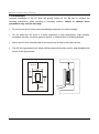
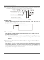
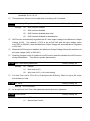
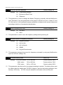
2.3 Installation:
Improper installation of the AC drive will greatly reduce its life. Be sure to observe the
following precautions when selecting a mounting location. Failure to observe these
precautions may void the warranty!
Do not mount the AC drive near heat-radiating elements or in direct sunlight.
Do not install the AC drive in a place subjected to high temperature, high humidity,
excessive vibration, corrosive gases or liquids, or airborne dust or metallic particles.
Mount the AC drive vertically and do not restrict the air flow to the heat sink fins.
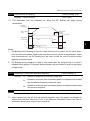
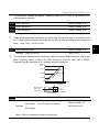
The AC drive generates heat. Allow sufficient space around the unit for heat dissipation as
shown in the figure below:
150mm
50mm
50mm
150mm
2-2
Air Flow
B550 Series sensorless vector frequency drive
CHAPTER 3
WIRING
DANGER
Hazardous Voltage
Before accessing the AC drive:
3
Disconnect all power to the AC drive.
Wait five minutes for DC bus capacitors discharge.
Any Electrical or mechanical modification to this equipment without prior written
consent of Delta Electronics, Inc. will void all warranties and may result in a safety
hazard in addition to voiding the UL listing.
Short Circuit Withstand:
Suitable for use on a circuit capable of delivering not more than 5,000 rms symmetrical
amperes, for all 460V Models, the maximum is 480 Volts, 230V Models, the maximum is 240
Volts.
General Wiring Information
Applicable Codes
All B550 AC drives are Underwriters Laboratories, Inc. (UL) and Canadian Underwriters
Laboratories (cUL) listed, and therefore comply with the requirements of the National Electrical
Code (NEC) and the Canadian Electrical Code (CEC).
Installation intended to meet the UL and cUL requirements must follow the instructions
provided in “Wiring Notes” as a minimum standard. Follow all local codes that exceed UL and
cUL requirements. Refer to the technical data label affixed to the AC drive and the motor
nameplate for electrical data.
The "Line Fuse Specification" in Appendix B, lists the recommended fuse part number for each
M-Series part number. These fuses (or equivalent) must be used on all installations where
compliance with U.L. standards is a required.
3-1
B550 Series sensorless vector frequency drive
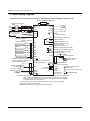
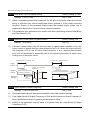
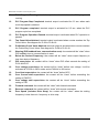
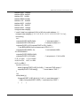
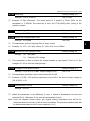
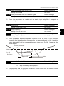
3.1 Basic Wiring Diagram
Users must connect wiring according to the following circuit diagram shown below.
Braking resistor (optional)
Main Circuit Power
NFB
R/L1
S/L2
T/L3
Recommended Circuit
when power supply
is turned OFF by a
fault output
R/L1 B1
S/L2
T/L3
SA
MC
OFF
ON
MC
The spec. of main circuit
terminal is M3.0
Factory default
Forward/Stop
Reverse/Stop
Reset
Multi-step 1
Multi-step 2
Multi-step 3
Common signal
Master Frequency setting
factory default is VR which is
on the digital keypad
3
Analog voltage
0~10VDC VR 2
VR:3K~5KΩ
RB
RC
B2
U/T1
V/T2
W/T3
E
RA
RB
M0
AC Motor
IM
3~
Grounding
Multi-function indication
output contact
120VAC/250VAC 5A
RC
24VDC less than 2.5A
Factory default:
indicates malfunction
MO1
Multi-function Photocoupler
output contact 48VDC 50mA
M1
M2
M3
Factory default: Indicates
MCM during operation
VR(1KΩ)
For adjustment
AFM
M4
M5
GND
E
Power for speed setting
+10V 10mA(MAX)
GND
E
RJ-11
+
-
Analog output
DC 0~ 10V
Factory default:
output frequency
Main circuit (power)
1:15V
terminals
2:GND
Control circuit terminals
3:SGAnalog current
ACI
4:SG+
GND
Shielded leads
5:Reserved
E
6:Reserved
NOTE: Do not plug a Modem or telephone line to the RS-485 communication
port, permanent damage may result. Terminal 1& 2 are the power
sources for the optional copy keypad and should not be used while
using RS-485 communication.
* If it is single phase model, please select any of the two input power
terminals in main circuit power.
* Single phase model can be input 3-phase power.
1
3-2
AVI
RS-485
series interface
6←1
B550 Series sensorless vector frequency drive
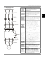
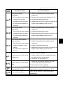
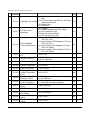
3.2 External Wiring
Items
Explanations
Please follow the specific power
Power
supply requirement shown in
supply
APPENDIX A.
There may be inrush current during
Fuse/NFB power up. Please check the chart of
APPENDIX B and select the correct
(Optional) fuse with rated current. NFB is
optional.
Power Supply
FUSE/NFB
Magnetic
contactor
Input AC
Line Reactor
Zero-phase
Reactor
EMI Filter
R/L1
S/L2
T/L3
B1
B2
U/T1
V/T2
Braking
Resistor
W/T3
Zero-phase
Reactor
Output AC
Line Reactor
Motor
Please do not use a Magnetic
Magnetic
contactor as the I/O switch of the AC
contactor
drive, this will reduce the operating
(Optional)
life cycle of the AC drive.
Used to improve the input power
factor, to reduce harmonics and
provide protection from AC line
disturbances. (Surge, switching
Input AC
spike, power flick, etc.). AC line
Line
reactor should be installed when the
Reactor
power supply capacity is ≧500kVA
(Optional)
or phase lead reactor will be
switched. And the wiring distance
should not exceed 10m. Please refer
to Appendix B for detail.
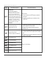
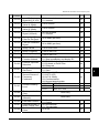
Zero-phase
Reactor
(Ferrite
Core
Common
Choke)
(Optional)
Zero phase reactors are used to
reduce radio noise especially when
audio equipment installed near the
inverter. Effective for noise reduction
on both the input and output sides.
Attenuation quality is good for a
wide range from AM band to 10Mhz.
Appendix B specifies zero phase
reactors. (RF220X00A)
To reduce electromagnetic
EMI filter
interference. Please refer to
(Optional)
Appendix B for detail.
Used to reduce stopping time of the
Braking
motor. Please refer to the chart on
Resistor
Appendix B for specific Braking
(Optional)
Resistors.
Output AC Motor surge voltage amplitudes
Line
depending on motor cable length.
Reactor For long motor cable applications
(Optional) (>10m), it is necessary to install on
the inverter output side.
3-3
3
B550 Series sensorless vector frequency drive
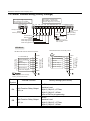
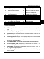
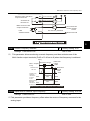
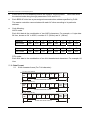
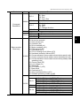
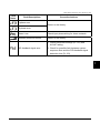
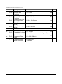
3.3 Control Terminal Wiring (Factory Settings)
Wire Type: Copper Only
Wire Gauge: 22-16 AWG
Torque: 2kgf-cm (1.73 in-lbf)
Wire Type: 75 C, Copper Only
Wire Gauge: 24-12 AWG
Torque: 4kgf-cm (3.5 in-lbf)
RA RB RC
M0
M1 M2 M3 M4 M5 GND AFM ACI+10V AVI GND MCM MO1
Relay contactor
Output
Factory Setting
4~20mA
Bias
Potentiometer
Forward/Stop
Reverse/Stop
Reset
Multi-step speed 1
Multi-step speed 2
Multi-step speed 3
Photo coupler
output
Factory setting:
fault indication
Full scale voltmeter
0 to 10 VDC
NPN Mode
N PN mo de wi th e xte rna l p ow e r
R ese t
Mu lti -ste p 1
Mu lti -ste p 2
Mu lti -ste p 3
C ommo n Si gn al
NOTE
M1
M2
M3
M4
M5
Factory Settin g
Factory Settin g
R eve rse /Sto p
M0
Mu lti -f un ctio n
In pu t Te rmin a ls
Fo rwa rd/St op
+2 4V
24 +
Vdc
Fo rwa rd/St op
R eve rse /Sto p
R ese t
Mu lti -ste p 1
Mu lti -ste p 2
Mu lti -ste p 3
+2 4V
M0
M1
M2
M3
M4
M5
GN D
GN D
E
E
Don' t a pply the mains v oltage
direc tly to abov e t erminals.
Terminal
Symbol
Terminal Function
Factory Settings (NPN mode)
RA-RC
RA
Multi-Function Relay Output
(N.O.) a
Resistive Load
5A(N.O.)/3A(N.C.) 277Vac;
5A(N.O.)/3A(N.C.) 30Vdc
Refer to P45 for programming.
RB-RC
RB
Multi-Function Relay Output
Resistive Load
(N.C.) b
5A(N.O.)/3A(N.C.) 277Vac;
5A(N.O.)/3A(N.C.) 30Vdc
3-4
Mu lti -f un ctio n
In pu t Te rmin a ls
N PN mo de wi th ou t ext ern al p o we r
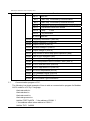
B550 Series sensorless vector frequency drive
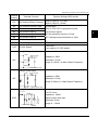
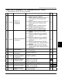
Terminal
Symbol
Terminal Function
RC
Multi-function Relay Common
M0
Multi-function auxiliary input
M0~M5-GND
M1
Multi-function input 1
M2
Multi-function input 2
Refer to P38~P42 for programming the
multi-function inputs.
M3
Multi-function input 3
ON: the activation current is 10 mA.
M4
Multi-function input 4
OFF: leakage current tolerance is 10μA.
M5
GND
Factory Settings (NPN mode)
5A(N.O.)/3A(N.C.) 277Vac;
5A(N.O.)/3A(N.C.) 30Vdc
3
Multi-function input 5
Common Signal
+10V-GND
+10V +10 Vdc Output
It can supply +10 VDC power.
Analog Voltage Input
+10V
AVI
AVI Circuit
AVI
ACM
Impedance: 20kΩ
Resolution: 10 bits
Range: 0~10Vdc = 0~Max.Output Frequency
Internal Circuit
Analog Current Input
ACI
ACI Circuit
Impedance: 250Ω
Resolution: 10 bits
Range: 4~20mA = 0~Max.Output Frequency
ACI
ACM
Internal Circuit
Analog Output Meter
ACM Circuit
0 to 10V, 2mA
AFM
0~10V
Potentiometer
Max. 2mA
AFM
Internal Circuit
Impedance: 100kΩ
Output Current: 2mA max
Resolution: 8 bits
Range: 0 ~ 10Vdc
ACM
3-5
B550 Series sensorless vector frequency drive
Terminal
Symbol
Terminal Function
Factory Settings (NPN mode)
Maximum: 48Vdc, 50mA
Refer to P45 for programming.
Max: 48Vdc/50mA
MO1-DCM
MO1
Multi-function Output Terminal
MO1
(Photocoupler)
Internal Circuit
MCM
Multi-function Output Common
(Photocoupler)
MCM
Common for Multi-function Outputs
Note: Use twisted-shielded, twisted-pair or shielded-lead wires for the control signal wiring. It
is recommended to run all signal wiring in a separate steel conduit. The shield wire
should only be connected at the drive. Do not connect shield wire on both ends.
3-6
B550 Series sensorless vector frequency drive
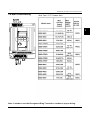
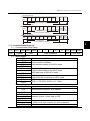
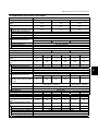
3.4 Main Circuit Wiring
o
Wire Type: 75 C Copper Only
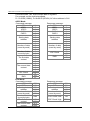
Model Name
B550-20R5(1-phase)
B550-2T0R5(3-phase)
Max.
Current
(input /
output)
Wire
Gauge
AWG
(mm2)
Torque
kgf-cm
(in-lbf)
12-14
(3.3-2.1)
14
(12)
3
6.3A/2.5A
3.2A/2.5A
B550-2001(1-phase)
11.5A/5.0A
VFD007M21B(3-phase)
6.3A/5.0A
VFD015M21B(1-phase)
15.7A/7.0A
12 (3.3)
VFD015M21B(3-phase)
9.0A/7.0A
12-14
(3.3-2.1)
VFD022M21A(1-phase)
27A/10A
8 (8.4)
VFD022M21A(3-phase)
15A/10A
8-12
(8.4-3.3)
VFD037M23A
19.6A/17A
8-10
(8.4-5.3)
VFD055M23A
28A/25A
8 (8.4)
VFD007M43B
4.2A/3.0A
12-14
(3.3-2.1)
VFD007M53A
2.4A/1.7A
12-14
(3.3-2.1)
VFD015M43B
5.7A/4.0A
12-14
(3.3-2.1)
VFD015M53A
4.2A/3.0A
12-14
(3.3-2.1)
VFD022M43B
6.0A/5.0A
12-14
(3.3-2.1)
VFD022M53A
5.9A/4.2A
12-14
(3.3-2.1)
VFD037M43A
8.5A/8.2A
8-14
(8.4-2.1)
VFD037M53A
7.0A/6.6A
8-14
(8.4-2.1)
VFD055M43A
14A/13A
8-12
(8.4-3.3)
VFD055M53A
10.5A/9.9A
8-12
(8.4-3.3)
VFD075M43A
23A/18A
8-10
(8.4-5.3)
VFD075M53A
12.9A/12.2A
8-12
(8.4-3.3)
15
(13)
14
(12)
15
(13)
Note: It needs to use the Recognized Ring Terminal to conduct a proper wiring.
3-7
B550 Series sensorless vector frequency drive
Terminal Explanations
Terminal Symbol
Explanation of Terminal Function
R/L1, S/L2, T/L3
AC line input terminals (three phase)
U/T1, V/T2, W/T3
Motor connections
B1 – B2
Connections for Braking Resistor (optional)
Earth Ground
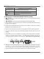
3.5 Wiring Notes: PLEASE READ PRIOR TO INSTALLATION.
1.
2.
! CAUTION: Do not connect the AC power to the U/T1, V/T2, W/T3 terminals, as it will
damage the AC drive.
!
WARNING: Ensure all screws are tightened to the proper torque rating.
3. During installation, follow all local electrical, construction, and safety codes for the country
the drive is to be installed in.
4. Ensure that the appropriate protective devices (circuit breaker or fuses) are connected
between the power supply and AC drive.
5. Make sure that the leads are connected correctly and the AC drive is properly grounded.
6. Use ground leads that comply with AWG/MCM standards and keep them as short as
possible.
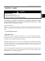
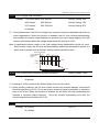
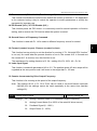
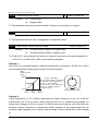
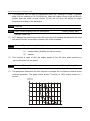
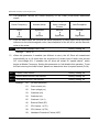
7. Multiple B550 units can be installed in one location. All the units should be grounded
directly to a common ground terminal. The B550 ground terminals may also be
connected in parallel, as shown in the figure below. Ensure there are no ground loops.
Forward
running
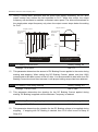
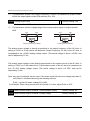
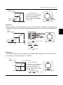
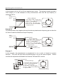
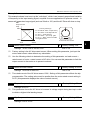
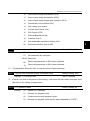
8. When the AC drive output terminals U/T1, V/T2, and W/T3 are connected to the motor
terminals U, V, and W, respectively, the motor will rotate counterclockwise (as viewed
from the shaft ends of the motor) when a forward operation command is received. To
reverse the direction of motor rotation, switch over any of the two motor leads.
3-8
B550 Series sensorless vector frequency drive
9. Make sure that the power source is capable of supplying the correct voltage and required
current to the AC drive.
10. Do not attach or remove wiring when power is applied to the AC drive.
11. Do not inspect components unless inside “CHARGE” lamp is turned off.
12. Do not monitor the signals on the circuit board while the AC drive is in operation.
13. For the single-phase rated AC drives, the AC power can be connected to any two of the
three input terminals R/L1, S/L2, T/L3. Note: This drive is not intended for the use
with single-phase motors.
14. Route the power and control wires separately, or at 90 degree angle to each other.
15. If a filter is required for reducing EMI (Electro Magnetic Interference), install it as close as
possible to AC drive. EMI can also be reduced by lowering the Carrier Frequency.
16. If the AC drive is installed in the place where a load reactor is needed, install the filter close
to U/T1, V/T2, W/T3 side of AC drive. Do not use a Capacitor or L-C Filter
(Inductance-Capacitance) or R-C Filter (Resistance-Capacitance), unless approved by
Delta.
17. When using a GFCI (Ground Fault Circuit Interrupt), select current sensor with sensitivity
of 200mA, and not less than 0.1-second detection to avoid nuisance tripping.
3.6 Motor Operation Precautions
1. When using the AC drive to operate a standard 3-phase induction motor, notice that the
energy loss is greater than for an inverter duty motor.
2. Avoid running a standard induction motor at low speed. Under these conditions, the motor
temperature may rise above the motor rating due to limited airflow produced by the motor’s
fan.
3. When the standard motor operates at low speed, the output load must be decreased.
4. If 100% output torque is desired at low speed, it may be necessary to use a special
“inverter-duty” rated motor.
3-9
3
B550 Series sensorless vector frequency drive
This page intentionally left blank.
B550 Series sensorless vector frequency drive
CHAPTER 4 DIGITAL KEYPAD OPERATION
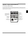
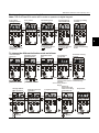
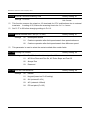
4.1 Description of Digital Keypad
The digital keypad includes two parts: Display panel and keypad. The display panel provides
the parameter display and shows the operation status of the AC drive and the keypad provides
programming and control interface.
4
DIGITAL KEYPAD
Program/Function mode key
Selects normal mode/
program mode. Displays
the AC drive status, such as
output freq., selects the
parameters.
Enter Key
Press ENTER after
key in the elected
parameters or
change data.
LED Display
Indicates motor and
drive parameter.
RUN
STOP
FWD
REV
MODE
RUN
ENTER
STOP
RESET
50
Potentiometer
For master Frequency
setting refer to Pr.00.
B550
LED Indicates
Lamp lights during RUN,
STOP, FWD & REV
operation.
Run key
Starts AC drive operation.
STOP/RESET Key
Stops and resets the
parameter after a fault
occurs.
UP and DOWN Key
Sets the parameter number
or changes the numerical
data such as the freq.
reference.
100
0
FREQ SET
LC-M02E
4-1
B550 Series sensorless vector frequency drive
Function / Program
MODE
Pressing the “mode” key repetitively displays the AC drive status such as the
reference frequency, output frequency, and output current.
Enter
ENTER
Pressing the “ENTER” key will store or display parameter settings.
Run
RUN
Starts AC drive operation. This key has no effect when the drive is controlled by
the External Control Terminals.
Stop / Reset
STOP
RESET
Used to stop AC drive operation. If the drive has stopped due to a fault, clear the
fault first, then press this key to reset the drive.
Up / Down
Press the “Up” or “Down” keys momentarily to change parameter settings. These
keys may also be used to scroll through different operating values or parameters.
Pressing the “Up” or “Down” key momentarily, will change the parameter settings in
single-unit increments. To quickly run through the range of settings, press and
hold the “DOWN” key.
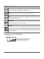
4.2 Explanation of the LED Indicators
LED Displays
RUN
STOP
FWD
REV
Green lamp lights during REV operation.
Green lamp lights during FWD operation.
Red lamp lights by pressing STOP.
Green lamp lights by pressing RUN.
4-2
B550 Series sensorless vector frequency drive
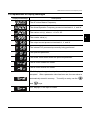
4.3 Explanations of Display Messages
Displayed Message
Descriptions
The AC drives Master Frequency.
The Actual Operation Frequency present at terminals U, V, and W.
The custom unit (v), where v = H x Pr.-65.
4
The counter value (c).
The output current present at terminals U, V, and W
The internal PLC process step currently being performed.
The specified parameter.
The actual value stored within the specified parameter.
The AC drive forward run status.
The AC drive reverse run status.
“End” displays for approximately 1 second if input has been
accepted. After a parameter value has been set, the new value is
automatically stored in memory.
and
To modify an entry, use the
keys.
“Err” displays, if the input is invalid.
4-3
B550 Series sensorless vector frequency drive
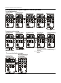
4.4 Explanation of Digital Keypad LC-M02E Operation
To view parameters:
Indication after
power on
Parameter values
setting monitor
Output frequency
Output current
FWD/REV monitor
Press
Press
Press
Press
Key
Key
Key
Key
Press
key
Display the freq.
setting monitor.
Parameter value setting:
Indication after
power on
Parameter values
setting monitor
Press
Press
Press
Press
Key
Key
Key
Key
Press
key to select the
parameter number
Press
key to select the
parameter number
To correct the fault messages:
Display frequency
setting after fault
is corrected.
Display fault
message o.H..
Press
Key
4-4
Parameter setting
monitor
The setting is
completed
Parameter value
is 01
"End":The new has
been automatically
stored in the internal
memory.
"Err": Enter value is
illegal.
Display the
parameter number
automatically.
B550 Series sensorless vector frequency drive
To change frequency, proceed as follows:
Note: The Pr.00 has to be set to d00 in order to operate via digital keypad.
Freq. value
setting monitor
Freq. set at
59.9 Hz.
Decreasing freq.
value to 0.0 Hz.
Press
Press
Press
Key
Key
Key
still
Increasing freq.
value to 60.0 Hz.
Frequency setting
monitor.
The value will be
increased with
3.5 Hz/sec, if press
key still.
The freq. value
can be entered
in stop or operating
mode.
4
The value will be
decreased with
3.5 Hz/sec, if press
key still.
Press
key to select the
monitor operating
frequency.
To change the different indication mode as follows:
Indication after
power on
Parameter values
setting monitor
Parameter setting
monitor
The setting is
completed
Parameter value
is 01
Press
Press
Press
Press
Key
Key
Key
Key
Press
key to select the
parameter number
Change FWD or
REV operation
Press
or
"End":The new has
Display the
been automatically
parameter number
stored in the internal automatically.
memory.
"Err": Enter value is
illegal.
AC driver
decelerates the
Stop mode
motor according
Frequency setting.
to the time set.
Press
key to select the
parameter number
Change to reserve
operation.
Press
Press
Press
Key
Key
Key
Key
lighten
glisten
lighten
lighten
glisten
4-5
B550 Series sensorless vector frequency drive
This page intentionally left blank.
B550 Series sensorless vector frequency drive
CHAPTER 5 DESCRIPTION OF PARAMETER SETTINGS
a: The parameter can be set during operation.
Pr.00 Source of Frequency Command
Settings
00
Master Frequency determined by digital keypad. (LC-M02E)
Master frequency determined by 0 to +10 V input
02
Master frequency determined by 4 to 20mA input
03
Master frequency determined by RS-485 Communication port
04
Master frequency determined by potentiometer on digital keypad.
(LC-M02E)
Factory Setting: 00
Operation instructions determined by the Digital Keypad.
01
Operation instructions determined by the External Control Terminals.
Keypad STOP key is effective.
03
04
Operation instructions determined by the External Control Terminals.
Keypad STOP key is not effective.
Operation instructions determined by the RS-485 communication
port. Keypad STOP key is effective.
Operation instructions determined by the RS-485 communication
port. Keypad STOP key is not effective.
Refer to Pr.38 to Pr.42 for more details.
Pr.02 Stop Method
Settings
a
00
02
Factory Setting: 00
01
Pr.01 Source of Operation Command
Settings
a
Factory Setting: 00
00
Ramp to stop
01
Coast to stop
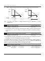
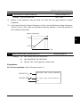
This parameter determines how the motor is stopped when the AC drive receives a valid
stop command.
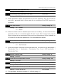
1.
Ramp: The AC drive decelerates the motor to Minimum Output Frequency (Pr.08) and
then stops according to the deceleration time set in Pr.11 or Pr.13.
5-1
5
B550 Series sensorless vector frequency drive
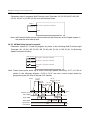
2.
Coast: The AC drive will stop the output instantly, and the motor will coast to stop.
Hz
Hz
Freq.
Freq.
Motor
Speed
Motor
Speed
Operation
command
Stops according
to deceleration
time
ON
Time
ON
OFF
OFF
Coast
Ramp
Note:
Time
Free running
to stop
The motor stop method is usually determined by the application or system
requirements.
Pr.03 Maximum Output Frequency
Factory Setting: 60.00
Settings 50.00 to 400.0 Hz
Unit: 0.1Hz
This parameter determines the AC drive’s Maximum Output Frequency. All the AC drive
analog inputs (0 to +10V, 4 to 20mA) are scaled to correspond to the output frequency
range.
Pr.04 Maximum Voltage Frequency (Base Frequency)
Settings 10.00 to 400.0Hz
Factory Setting: 60.00
Unit: 0.1Hz
This parameter should be set according to the rated frequency as indicated in the motor
nameplate. Pr.04 and Pr.03 determine the volts per hertz ratio.
For example: if the drive is rated for 460 VAC output and the Maximum Voltage Frequency is
set to 60Hz, the drive will maintain a constant ratio of 7.66 v/Hz. Setting of Pr.04 must be
equal to or greater than setting of Mid-Point Frequency (Pr.06).
Pr.05 Maximum Output Voltage (Vmax)
Settings
230V series
460V series
5-2
0.1 to 255.0V
Factory Setting: 220.0
0.1 to 510.0V
Factory Setting: 440.0
B550 Series sensorless vector frequency drive
This parameter determines the Maximum Output Voltage of the AC drive. The Maximum
Output Voltage setting must be smaller than or equal to the rated voltage of the motor as
indicated on the motor nameplate. Setting of Pr.05 must be equal to or greater than
setting of Mid-Point Voltage (Pr.07).
Pr.06 Mid-Point Frequency
Factory Setting: 1.50
Settings 0.10 to 400.0Hz
Unit: 0.1Hz
The parameter sets the Mid-Point Frequency of V/F curve. With this setting, the V/F ratio
between Minimum Frequency and Mid-Point frequency can be determined. Setting of
this parameter must be equal to or greater than Minimum Output Frequency (Pr.08)
and equal to or less than Maximum Voltage Frequency (Pr.04).
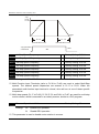
Pr.07 Mid-Point Voltage
5
Settings 230V series
0.1 to 255.0V
Factory Setting: 10.0
460V series
0.1 to 510.0V
Factory Setting: 20.0
The parameter sets the Mid-Point Voltage of any V/F curve. With this setting, the V/F ratio
between Minimum Frequency and Mid-Point Frequency can be determined. Setting of
this parameter must be equal to or greater than Minimum Output Voltage (Pr.09)
and equal to or less than Maximum Output Voltage (Pr.05).
Pr.08 Minimum Output Frequency
Factory Setting: 1.50
Settings 0.10 to 20.00Hz
Unit: 0.1Hz
The parameter sets the Minimum Output Frequency of the AC drive. Setting of this
parameter must be equal to or less than Mid-Point Frequency (Pr.06).
Pr.09 Minimum Output Voltage
Settings
230V series
0.1 to 255.0V
Factory Setting: 10.0
460V series
0.1 to 510.0V
Factory Setting: 20.0
This parameter sets the Minimum Output Voltage of the AC drive.
Setting of this
parameter must be equal to or less than Mid-Point Voltage (Pr.07).
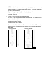
5-3
B550 Series sensorless vector frequency drive
Voltage
Pr.05
Pr.07
Pr.09
0
Frequency
Pr.06
Pr.08
Pr.03
Pr.04
Voltage
Pr.05
Pr.07
Pr.09
Pr.08
Pr.06
Pr.04
Frequency
Pr.03
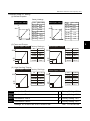
Custom V/F Curve
Voltage
Pr.05
Pr.07
Pr.09
Pr.08
Pr.06
Pr.04
Fan/Pump V/F Curve
5-4
Frequency
Pr.03
B550 Series sensorless vector frequency drive
Commonly used V/F Setting
(1) General Purpose
Factory Settings
Motor Spec. 60Hz
V
220
10
1.5
60.0 f
No.
Set value
Pr.03
60.0
Pr.04
60.0
Pr.05
Pr.06
220.0
1.5
Pr.07
10.0
Pr.08
Pr.09
1.5
10.0
(2) Fans and Pumps
Motor Spec. 60Hz Factory Settings
V
No. Set value
60.0
220
Pr.03
Pr.04
Pr.05
Pr.06
Pr.07
Pr.08
Pr.09
50
10
1.5 30
60.0
220.0
30
50.0
1.5
10.0
23
18
60.0f
Pr.04
220
Pr.05
Pr.06
Pr.07
Pr.08
10
1.5
60.0
220.0
3
23.0
1.5
18.0
50.0 f
Pr.09
Set value
50.0
50.0
220.0
1.3
12.0
1.3
12.0
5
Motor Spec. 50Hz
V
220
50
10
1.3 25
Pr.04
Pr.05
Pr.06
Pr.07
Pr.08
Pr.09
No.
Pr.03
V
60.0f
(3) High Starting Torque
Motor Spec. 60Hz Factory Settings
V
No. Set value
60.0
220
Pr.03
1.5 3
Motor Spec. 50Hz
Set value
50.0
50.0
220.0
25
50.0
1.3
10.0
50.0f
Motor Spec. 50Hz
V
220
23
14
1.3 2.2
No.
Pr.03
Pr.04
Pr.05
Pr.06
Pr.07
Pr.08
Pr.09
No.
Pr.03
Pr.04
Pr.05
Pr.06
Pr.07
Pr.08
Pr.09
Set value
50.0
50.0
220.0
2.2
23.0
1.3
14.0
60.0f
Pr.10 Acceleration Time 1
a Factory Setting: 10.0
Pr.11 Deceleration Time 1
a Factory Setting: 10.0
Pr.12 Acceleration Time 2
a Factory Setting: 10.0
Pr.13 Deceleration Time 2
a Factory Setting: 10.0
Settings 0.1 to 600.0 sec or 0.01 to 600.0 sec
Unit: 0.1 or 0.01 sec
5-5
B550 Series sensorless vector frequency drive
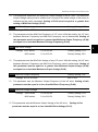
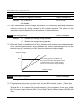
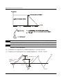
Pr.10. This parameter is used to determine the time required for the AC drive to ramp
from 0 Hz to its Maximum Output Frequency (Pr.03). The rate is linear unless the
S-Curve (Pr.14) is “Enabled”.
Pr.11. This parameter is used to determine the time required for the AC drive to
decelerate from the Maximum Output Frequency (Pr.03) down to 0 Hz. The rate is linear
unless the S-Curve (Pr.14) is “Enabled”.
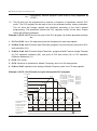
Pr.12 and Pr.13: Provide an additional Accel/Decel time although Time 1 is the default. A
Multi-Function input terminal must be programmed to select Accel/ or Decel/ Time 2 and
the terminal must be closed to select Accel/Decel Time 2 (See Pr.38 to Pr.42).
In the below diagram, suppose the Maximum Output Frequency is 60 Hz (Master Freq),
Minimum Output Frequency (start-up) is 1.0 Hz, and accel/decel time 1 is 10 seconds.
The actual time for the AC drive to accelerate from start-up to 60 Hz is 9.83 seconds
(deceleration time is also 9.83 seconds), can be determined by the formula.
Frequency
Max.
Output
Freq.
Actual Acceleration/Deceleration Time=
Acceleration/Deceleration Time x(Master Freq.-Min.Output Freq.)
Max. Output Freq.
Pr.10
or
Pr. 12
Acceleration Time
Time
Pr.11
or
Pr. 13
Deceleration Time
Pr.14 Acceleration S-Curve
Factory Setting: 00
Settings 00 to 07
This parameter is used whenever the motor load needs to be accelerated or decelerated
smoothly. The desired accel/decel effect is selectable from 0 to 7, in which the larger the
number, the greater the effect achieved. If the default value of Pr.111 Deceleration S
Curve is unchanged (“0”), then Pr.14 sets both acceleration and deceleration S-Curves. If
Pr.111 is set to any value other than “0”, then Pr.14 will set the acceleration S-Curve and
Pr.111 will set the deceleration S-Curve.
5-6
es
B550 Series sensorless vector frequency drive
Freq.
Acceleration/Deceleration characteristics
(1), (2) Disabling S curve
(3), (4) Enabling S curve
Pr.15 Jog Accel / Decel Time
a
Settings 0.1 to 600.0 sec or 0.01 to 600.0 sec
Factory Setting: 1.0 sec
Unit: 0.1 or 0.01 sec
This parameter sets the acceleration or deceleration time for Jog operation.
Pr.16 Jog Frequency
Settings 0.00 to 400.0 Hz
a
Factory Setting: 6.00 Hz
Unit: 0.1 Hz
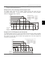
When the JOG function is activated, the AC drive will accelerate from Minimum Output
Frequency (Pr.08) to Jog Frequency (Pr.16). Drive must be in “stop” status for the
operator to activate the JOG function. Likewise, during Jog operation, other commands
cannot be accepted through the keypad but FORWARD, REVERSE and STOP. The
JOG function can be remotely activated when the Jog terminal is closed, and if the Jog
terminal opens, the AC drive will decelerate from Jog Frequency to zero. The accel /
decel time is entered as Jog Accel / Decel Time (Pr.15). Multi-function Input terminals
(M1-M5) can also be used to initiate the JOG operation if so programmed.
5-7
5
B550 Series sensorless vector frequency drive
Frequency
Jog
Freq.
Pr.16
Time
Pr. 15
Pr. 15
Acceleration Time
Deceleration Time
Jog operation
command
OFF
ON
Pr.17 1st Step Speed Frequency
a
Factory Setting: 0.00 Hz
Pr.18 2nd Step Speed Frequency
a
Factory Setting: 0.00 Hz
Pr.19 3rd Step Speed Frequency
a
Factory Setting: 0.00 Hz
Pr.20 4th Step Speed Frequency
a
Factory Setting: 0.00 Hz
Pr.21 5th Step Speed Frequency
a
Factory Setting: 0.00 Hz
Pr.22 6th Step Speed Frequency
a
Factory Setting: 0.00 Hz
Pr.23 7th Step Speed Frequency
a
Factory Setting: 0.00 Hz
Settings
0.00 to 400.0Hz
Unit: 0.1 Hz
Multi-Function Input Terminals (refer to Pr.38 to Pr.42) are used to select Multi-Step
speeds. The desired speed frequencies are entered in Pr.17 to Pr.23. When the
associated multi-function input terminal is closed, drive will run at one of these specific
frequencies.
Multi-step speeds (Pr.17 to Pr.23), Pr.78, Pr.79, and Pr.81 to Pr.87; are used for multi-step
motion control, which is executed in an orderly manner, similar to a PLC program.
Pr.24 Reverse Operation Inhibition
Settings
00
Enable REV operation
01
Disable REV operation
This parameter is used to disable motor rotation in reverse.
5-8
Factory Setting: 00
B550 Series sensorless vector frequency drive
Pr.25 Over–Voltage Stall Prevention
Settings 115V/230V series 330-450Vdc
Factory Setting: 390
460V series
660-900Vdc
Factory Setting: 780
575V series
825-1025Vdc
Factory Setting: 975
00 disable
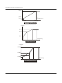
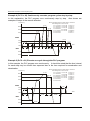
During deceleration, the DC bus voltage may exceed its maximum allowable value due to
motor regeneration. When this function is enabled, the AC drive will stop decelerating,
and maintain a constant output frequency to prevent from over-voltage tripping. Drive will
resume deceleration when the voltage drops below the setting for Pr.25.
Note: In applications where inertia is low, over-voltage during deceleration would not occur.
When inertia is high, the AC drive will automatically extend the deceleration period. If a
faster stop is needed, then a dynamic braking resistor should be used.
DC bus voltage
Over-voltage
detection
level
time
output
Freq.
time
Over-voltage Stall Prevention
Pr.26 Over-Current Stall Prevention during Acceleration
Settings 20 to 200%
Factory Setting: 150%
Unit: 1%
00 disable
A setting of 100% is equal to the Rated Output Current of the drive.
Under certain conditions, the AC drive output current may increase abruptly, and exceed
the value specified by Pr.26. This is commonly caused by rapid acceleration or excessive
load on the motor. When this function is enabled, the AC drive will stop accelerating and
maintain a constant output frequency. Drive will resume accelerating only after the
current drops below the setting for Pr.26.
Pr.27 Over-Current Stall Prevention during Operation
Settings 20 to 200%
Factory Setting: 150%
Unit: 1%
00: disable
5-9
5
B550 Series sensorless vector frequency drive
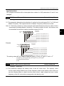
During a steady-state operation with the motor load rapidly increasing, the AC drive
output current may exceed the limit specified in Pr.27. When this occurs, the output
frequency will decrease to maintain a constant motor speed. The drive will accelerate to
the steady-state output frequency only when the output current drops below the setting
for Pr.27.
output current
Output current
over-current
detection
level
over-current
detection
level
Pr.27
time
time
output
frequency
output
freq.
time
over-current Stall Prevention
during Acceleration
Pr.28 DC Braking Current Level
Settings 00 to 100%
time
Over-current Stall Prevention
during Operation
Factory Setting: 00
Unit: 1%
This parameter determines the amount of DC Braking Current applied to the motor during
starting and stopping. When setting the DC Braking Current, please note that 100%
corresponds to the rated current of the AC drive. It is recommended to start with a low DC
Braking Current level and then increase it until proper holding torque has been attained.
Pr.29 DC Braking Time during Start-up
Settings 0.0 to 5.0 sec
This parameter determines the duration for the DC Braking Current applied during
starting. DC Braking is applied until the Minimum Frequency is reached.
Pr.30 DC Braking Time during Stopping
Settings 0.0 to 25.0 sec
Factory Setting: 0.0
Unit: 0.1sec
This parameter determines the duration for the DC Braking voltage to be applied during
stopping.
Stop (0.0).
5-10
Factory Setting: 0.0
Unit: 0.1sec
If stopping with DC Braking is desired, then Pr.02 must be set to Ramp to
B550 Series sensorless vector frequency drive
Pr.31 Start-Point for DC Braking
Factory Setting: 0.00
Settings 0.00 to 60.00Hz
Unit: 0.1sec
This parameter sets the frequency at which the DC Braking will begin during
deceleration.
Master
Frequency
Min. output
Freq.
Operation
command
Pr.31
Pr.29
Start-point
for DC
braking
time(s)
Pr.30
ON
OFF
5
DC Braking Current %
Pr.28
Notes:
1.
DC Braking during starting is used for loads that may move before the AC drive starts,
such as hoists and cranes. These loads may also be moving in the wrong direction. Under
such circumstances, the DC Braking can be used to hold the load in position before
applying a forward motion.
2.
DC Braking during stopping is used to stop faster than the ramp-to-stop or to hold a
stopped load in position. A dynamic braking resistor may be needed in order to stop loads
of high inertia.
Pr.32 Momentary Power Loss Operation Selection
Settings
00
01
02
Operation continues after momentary power loss Speed search starts
with the Master Frequency reference value
Operation continues after momentary power loss Speed search starts
with the min frequency
Pr.33 Maximum Allowable Power Loss Time
Settings 0.3 to 5.0 sec
Factory Setting: 00
Operation stops after momentary power loss
Factory Setting: 2.0 sec
Unit: 0.1sec
After a power loss, the AC drive will resume operation only if the power loss duration is
shorter than the time defined by Pr.33. If the Maximum Allowable Power Loss Time is
exceeded, the AC drive output is then turned off.
5-11
B550 Series sensorless vector frequency drive
Pr.34 Base-Block Time for Speed Search
Factory Setting: 0.5 sec
Settings 0.3 to 5.0 sec
Unit: 0.1sec
When a momentary power loss is detected, the AC drive will stop its output and will wait
during a specified time interval called Base Block (entered in Pr.34) before resuming
operation. Setting of this parameter should make the residual output voltage due to
regeneration almost zero, before the drive resumes operation.
This parameter also determines the search time when performing external Base-Block
and Fault Reset (Pr.72).
Pr.35 Maximum Current Level for Speed Search
Factory Setting: 150
Settings 30 to 200%
Unit: 1%
Following a power failure, the AC drive will start its speed search operation only if the
output current is greater than the value determined by Pr.35. When the output current is
less than that of Pr.35, the AC drive output frequency is at a “speed synchronization
point” and will accelerate or decelerate back to the operating frequency at which it was
running prior to the power failure.
Allowable Max. Power Loss Time
Input
Power
Output
Power
Output
Voltage
Pr.33
Allowable Max. power loss time
Pr.33
speed synchronization
detection
Pr.32=1
Speed search starts with
the Master Frequency
Baseblock
Time
Pr.32=2
Speed search starts with
minimum output frequency
Baseblock
Time
Pr.34
Pr.34
speed search
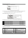
Pr.36 Upper Bound of Output Frequency
Settings 0.10 Hz to 400.0 Hz
Factory Setting: 400
Unit: 0.1Hz
The Upper/Lower Bounds help prevent operation error and machine damage.
If the Upper Bound of Output Frequency is 50Hz and the Maximum Output Frequency is
60Hz, the Maximum Output Frequency will be limited to 50Hz.
Setting of this parameter must be equal to or greater than the Lower Bound of Output
Frequency (Pr.37).
5-12
B550 Series sensorless vector frequency drive
Pr.37 Lower Bound of Output Frequency
Factory Setting: 0 Hz
Settings 0.00 Hz to 400.0 Hz
Unit: 0.1Hz
Setting of this parameter must be equal to or less than the Upper Bound of Output
Frequency
If the Lower Bound of Output Frequency is 10Hz, and the Minimum Output Frequency
(Pr.08) is set at 1.0Hz, then any command frequency between 1-10Hz will generate a
10Hz output from the drive.
output frequency
Pr.36
5
Pr.37
Input Freq.
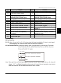
Pr.38 Multi-function Input Terminal (M0, M1)
Settings
Factory Setting: 00
00
M0: FWD/STOP, M1: REV/STOP
01
M0: RUN/STOP, M1: REV/FWD
02
M0, M1, M2: 3-wire operation control mode
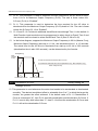
Explanations:
00: Two wire operation: Only Pr.38 can be set to “0”.
FWD/STOP
REV/STOP
M0 "Open": Stop, "Close": FWD Run
M1 "Open": Stop, "Close":REV Run
GND
5-13
B550 Series sensorless vector frequency drive
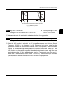
01: Two wire operation: Only Pr.38 can be set to “1”.
RUN/STOP
M0 "Open": Stop, "Close": Run
M1 "Open": FWD, "Close":REV
REV/FWD
GND
Note: Multi-function Input Terminal M0 does not have its own parameter designation. M0
must be used in conjunction with M1 to operate two and three wire control.
02 Three Wire Control: Only Pr.38 can be set to “2”.
STOP
RUN
M0 Run command, Runs when "close"
M2 Stop command, stops when "Open"
M1 REV/FWD Run selection
RUN/FWD "Open": FWD Run
"Close": REV Run
GND
Note: When the “2” setting is selected for Pr.38, the value in Pr.39 will be ignored.
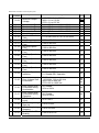
Pr.39 Multi-function Input Terminal (M2)
Factory Setting: 05
Pr.40 Multi-function Input Terminal (M3)
Factory Setting: 06
Pr.41 Multi-function Input Terminal (M4)
Factory Setting: 07
Pr.42 Multi-function Input Terminal (M5)
Factory Setting: 08
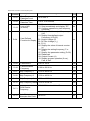
Settings 00 to 32
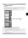
Parameters & Functions table:
Value
00
02
04
06
5-14
Function
No Function
Output OFF (N.C.) (enabled when
running)
External Fault (N.C.)
Multi-Step Speed Command 1
Value
01
Function
Output OFF (N.O.) (enabled when
running)
03
External Fault (N.O.)
05
07
External Reset
Multi-Step Speed Command 2
B550 Series sensorless vector frequency drive
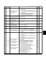
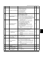
Value
Function
08
Multi-Step Speed Command 3
10
Accel/Decel Speed Inhibit
14
16
18
20
22
External Base Block (N.O.)
(Normally Open Contact Input)
Increase Master Frequency
Run PLC Program
Counter Trigger Signal
No Function
Control source: External Terminal
24
Control source: Communication
26
30
PID Disable (N.O.)
Second Source for Frequency
Command
One-Shot PLC Run
32
Virtual Timer Input
12
28
Value
Function
09 Jog Operation
First or Second Accel/Decel Time
11
Selection
External Base Block (N.C.)
13
(Normally Close Contact Input)
15 Decrease Master Frequency
17 Pause PLC Program
19 Counter Reset
21 RESET Command (N.C)
23 Control source: Keypad
Parameter Lock (Write disable, Read is
25
always 0)
27 PID Disable (N.C.)
29
31
Forward (contact is open) / Reverse
(contact is close)
Index Input Signal
Explanations:
00: no function.
01, 02: when it is set to 01 or 02, AC drive output will stop immediately. If there is start signal
after stopping, the output will start from the minimum frequency.
03, 04 External Faults: Parameter values 3 and 4 program Multi-Function Input Terminals:
M1 (Pr.38), M2 (Pr.39), M3 (Pr.40), M4 (Pr.41) or M5 (Pr.42) to be
External Fault (E.F.) inputs.
E.F.(N.O.)
setting by 3
E.F(N.C.)
setting by 4
Mx "Close": Operation available.
Mx "Open":Operation available.
GND
Note: When an External Fault input signal is received, the AC drive output will turn off, drive will
display “ E.F.” on Digital Keypad, and the motor will coast. Normal operation can resume
after the External Fault is cleared and the AC drive is reset.
5-15
5
B550 Series sensorless vector frequency drive
05 External Reset:
Parameter value 5 programs Multi-Function Input Terminals: M1 (Pr.38), M2 (Pr.39), M3
(Pr.40), M4 (Pr.41) or M5 (Pr.42) to be an External Reset.
RESET
Mx "Close": Operation avalilable
setting by 5
GND
Note: the External Reset has the same function as the Reset key on the Digital keypad. It
will reset the drive after a fault.
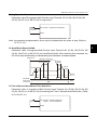
06, 07, 08 Multi-Step Speed Command:
Parameter values 06, 07,and 08 program any three of the following Multi-Function Input
Terminals: M1 (Pr.38), M2 (Pr.39), M3 (Pr.40), M4 (Pr.41) or M5 (Pr.42) for Multi-step
Speed Command function.
d6 Multi-step 1
Mx "Close": Operation available
d7 Multi-step 2
Mx "Close": Operation available
d8 Multi-step 3
Mx "Close": Operation available
GND
Note: These three inputs select up to seven multi-step speeds defined by Pr.17 to Pr.23 as
shown in the following diagram. Pr.78 to Pr.87 can also control output speed by
programming the AC drive’s internal PLC function.
Freq.
Pr.17
Pr.21
Step 1
Step 5
Pr.22
Pr.18
Step 6
Step 2
Pr.20
Step
4
Pr.19
Pr.23
Step 3
Step 7
Time
Master Freq.
Mx1-GND
Mx2-GND
Mx3-GND
Operation
Command
5-16
ON
ON
ON
ON ON
ON
ON ON
ON ON ON ON
ON
OFF
B550 Series sensorless vector frequency drive
09 Jog Operation Control:
Parameter value 09 programs Multi-Function Input Terminal: M1 (Pr.38), M2 (Pr.39), M3
(Pr.40), M4 (Pr.41) or M5 (Pr.42) for Jog control.
Mx "Close": Operation available
9 jog operation
command
GND
Note: Jog operation programmed by 9 can only be initiated while the motor is stop. (Refer to
Pr.15, Pr.16.)
5
10 Accel/Decel Speed Inhibit:
Parameter value 10 programs Multi-Function Input Terminal: M1 (Pr.38), M2 (Pr.39), M3
(Pr.40), M4 (Pr.41) or M5 (Pr.42) for Accel/Decel Inhibit. After receiving this command, the
AC Drive stops accelerating or decelerating and maintains a constant speed.
Frequency
Master Frequency
Accel inhibit
Decel
inhibit
Decel
inhibit
Accel inhibit
Actual operation frequency
Time
Mx-GND
ON
ON
Operation
command
ON
ON
ON
OFF
11 First or Second Accel/Decel Time Selection:
Parameter value 11 programs a Multi-Function Input Terminal: M1 (Pr.38), M2 (Pr.39), M3
(Pr.40), M4 (Pr.41) or M5 (Pr.42) for selecting the First or Second Accel/Decel time. (Refer
to Pr.10 to Pr.13.)
Mx set 11
Mx "Close": 2nd Accel/Decel
"Open": 1st Accel/Decel
GND
5-17
B550 Series sensorless vector frequency drive
Frequency
Master
Frequency Pr.10
Pr.11 Pr.12
1st
Accel
2nd
Accel/
Decel
1st
Accel/
Decel
Pr.13
Pr.13 Pr.10
2nd
Decel
Time
ON
ON
Mx-GND
operation
command
ON
ON
ON
OFF
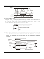
12, 13 External Base Block:
Parameter values 12, 13 program Multi-Function Input Terminals: M1 (Pr.38), M2 (Pr.39),
M3 (Pr.40), M4 (Pr.41) or M5 (Pr.42) for external Base Block control. Value 12 is for
normally open (N.O.) input, and value 13 is for a N.C. input.
B.B.(N.O.)
setting by 12
B.B.(N.C.)
setting by 4
Mx "Close": Operation available.
Mx "Open":Operation available.
GND
Note: When a Base-Block signal is received, the AC drive will stop all output and the motor will
coast. When base block control is deactivated, the AC drive will start its speed search
function and synchronize with the motor speed, and then accelerate to the Master
Frequency.
Allowable max. power loss time
External
base-block
signal
Output
frequency
Output
voltage
Capacitor
discharge
Pr.33
Pr.32=1
Speed search starts with the
reference value
Low voltage
Pr.34
Min. base-block time
Low voltage
5-18
Speed synchronization
detection
Speed search operation
B550 Series sensorless vector frequency drive
14, 15 Increase/Decrease Master Frequency:
Parameter values 14, 15 program the Multi-Function Input Terminals: M1 (Pr.38), M2
(Pr.39), M3 (Pr.40), M4 (Pr.41) or M5 (Pr.42) to incrementally increase/ decrease the
Master Frequency each time an input is received.
UP
Mx "Close": Freq. will increase
by one unit.
setting by 14
DOWN
Mx "Open":Freq. will decrease
by one unit.
setting by 15
GND
16, 17 PLC Function Control:
Parameter value 16 programs Multi-Function Input Terminal: M1 (Pr.38), M2 (Pr.39), M3
(Pr.40), M4 (Pr.41) or M5 (Pr.42) to enable the AC drive internal PLC program. Parameter
value 17 programs an input terminal to pause the PLC program.
PLC operation
setting by 16
setting by 17
Mx "Close": Run PLC.
Mx "Open":Pause PLC.
GND
Note: Pr.17 to Pr.23, Pr.78, Pr. 79, Pr.81 to Pr.87 define the PLC program. Another related
function is “30 One-Shot PLC Run”. It can be set to use a not-latched contact as the
run signal.
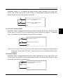
18 Counter Trigger:
Parameter value 18 programs Multi-Function Input Terminal: M1 (Pr.38), M2 (Pr.39), M3
(Pr.40), M4 (Pr.41) or M5 (Pr.42) to increase the AC drive’s internal counter. When an input
is received, the counter is increased by 1.
Trigger
Mx counter value increase by
1 when closed.
18 counter
trigger signal
input.
GND
5-19
5
B550 Series sensorless vector frequency drive
Note: The Counter Trigger input can be connected to an external Pulse Signal Generator when
counting a process step or unit of material. See the diagram below.
2ms
Indication value
(Pr.64=1)
Counter trigger signal
Multi-function input terminal
(Pr.38 to Pr.42 =18)
2ms
Signal output with Pr.97 (Pr.97=3)
counter value is attained. (Pr.45/46=13)
The trigger timing
can't be less than
2ms.(<250Hz)
Signal output with Pr.96 (Pr.96=5)
counter value is attained. (Pr.45/46=14)
19 Counter Reset:
Parameter value 19 programs Multi-Function Input Terminal: M1 (Pr.38), M2 (Pr.39), M3
(Pr.40), M4 (Pr.41) or M5 (Pr.42) to reset the counter.
Reset counter
Mx "close": reset counter.
19 reset the
counter value.
GND
20 Parameter Disable:
Enter value (20) to disable any Multi-Function Input Terminal: M1 (Pr.38), M2 (Pr.39), M3
(Pr.40), M4 (Pr.41) or M5 (Pr.42)
Note: Purpose of this function is to isolate unused Multi-Function Input Terminals. Any
unused terminals should be programmed to 20 to insure they have no effect on drive
operation.
22 Control Source: External Terminal / 23 Control Source: Keypad / 24 Control Source:
Communication:
Enter values 22, 23, or 24 to set the control source to be the external terminals, keypad or
communication respectively. This setting is used to create functions for manual/auto, and
remote/near-end control. When these three functions are used at the same time, the
priority is 22-I/O > 23-Keypad > 24-Communication.
5-20
B550 Series sensorless vector frequency drive
25 Parameter Lock (Write disable, Read is always 0)
This function will disable the write function and all the content of read are 0. The application
is for customer having a key to control the operator to modify parameters or modify the
parameter by improper use.
26 PID Disable (N.O.) / 27 PID Disable (N.C.)
This function pause the PID control. It is commonly used for manual operation or function
testing, and to recover the PID function when the system is normal.
28 Second Source of Frequency Command
This function is used with Pr. 142 to select a different frequency source for control.
5
29 Forward (contact is open) / Reverse (contact is close)
This function has top priority to set the direction for running (If “Pr. 24 inhibit REV function”
is not set). No mater what the present direction of run is, the contact N.O. is forward and
the contact N.C. is reverse, once this function is set.
The requirement for setting direction is Pr. 24 > setting 29 of Pr. 39-Pr. 42 > Pr. 38.
31 Index Input Signal
This function is used with parameters 149 to 151. The position where AC drive stops will be
regarded as the zero position and it will move to the angle that Pr. 150 sets.
32 Counter Incremented by Drive Output Frequency
This function is for counting at the speed of the output frequency.
Note: The settings 00~32 in Pr. 39 to Pr.42 can be used to set multi-function terminals
(M2-M5) but the settings cannot be used repeatedly at the same time (besides
settings 20).
Pr.43 Analog Output Signal
Settings
a Factory Setting: 00
00
Analog Frequency Meter (0 to Maximum Output Frequency)
01
Analog Current Meter (0 to 250% of the rated AC drive current)
02
Feedback Signal (0 - 100%)
03
Output Power (0 - 100%)
5-21
B550 Series sensorless vector frequency drive
This parameter selects if the Output Frequency, Current, PID feedback or Output Power
will be the output signal on the AFM terminal (0 to 10V).
Pr.44 Analog Output Gain
a Factory Setting: 100
Settings 00 to 200%
Unit: 1%
This parameter sets the voltage range of the analog output signal on output terminal
AFM.
AFM
GND
+
-
Analog Frequency Meter
AFM
GND
+
-
Analog Current Meter
The analog output voltage is directly proportional to the output frequency of the AC drive. A
setting of 100% on Pr.44 makes the Maximum Output Frequency (Pr.03) of the AC drive to
correspond to the +10VDC analog voltage output. (The actual voltage is about +10VDC, and
can be adjusted by Pr.44)
The analog output voltage is also directly proportional to the output current of the AC drive. A
setting of 100% on Pr.44 makes the 2.5 times rated current of the AC drive to correspond to
the +10 VDC analog voltage output. (The actual voltage is about +10 VDC, and can be
adjusted by Pr.44)
Note: Any type of voltmeter can be used. If the meter reads full scale at a voltage less than 10
volts, then Pr.44 should be set by the following formula:
Pr.44 = ((meter full scale voltage)/10)×100%
For Example: When using a meter with a full scale of 5 volts, adjust Pr.44 to 50%
Pr.45 Multi-function Output Terminal 1 (Photocoupler output)
Factory Setting: 00
Pr.46 Multi-function Output Terminal 2 (Relay output)
Factory Setting: 07
Settings 00 to 24
5-22
B550 Series sensorless vector frequency drive
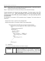
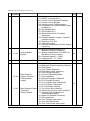
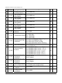
Function Table List:
Setting
00
01
Functions
Setting
AC Drive Operational
Maximum Output Frequency
Attained
Functions
13
Top Count Value Attained
14
Preliminary Counter Value Attained
02
Zero speed
15
03
04
05
06
07
08
09
10
11
12
Over-Torque detection
Base-Block (B.B.) Indication
Low-Voltage Indication
AC Drive Operation Mode
Fault Indication
Desired Frequency attained
PLC Program Running
PLC Program Step Completed
PLC Program Completed
PLC Operation Paused
16
17
18
19
20
21
22
23
24
Warning (PID feedback loss,
communication error)
Below the Desired Frequency
PID supervision
Over Voltage supervision
Over Heat supervision
Over Current stall supervision
Over Voltage stall supervision
Forward command
Reverse command
Zero Speed (Includes Drive Stop)
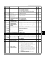
Function Explanations:
00
AC Drive operational: terminal output is activated when there is power output from
drive.
01
Maximum Output Frequency Attained: terminal output is activated when the AC
drive attains Maximum Output Frequency.
02
Zero speed: terminal output is activated when Command Frequency is lower than the
Minimum Output Frequency.
03
Over-Torque Detection: terminal output is activated when over-torque is detected.
Parameter Pr.61 determines the Over-Torque detection level.
04
Base-Block (B.B.) Indication: terminal output is activated when the AC drive output is
shut-off by the external Base-Block.
05
Low Voltage Indication: terminal output is activated when low voltage is detected.
06
AC Drive Operation Mode: terminal output is activated when the operation of AC
Drive is controlled by External Control Terminals.
07
Fault Indication: terminal output is activated when certain faults occur (oc, ov, oH, oL,
oL1, EF, cF3, HPF, ocA, ocd, ocn, GF).
08
Desired Frequency Attained: terminal output is activated when the desired frequency
(Pr.47) is attained.
5-23
5
B550 Series sensorless vector frequency drive
09
PLC Program Running: terminal output is activated when the PLC program is
running.
10
PLC Program Step Completed: terminal output is activated for 0.5 sec. when each
multi-step speed is attained.
11
PLC Program completed: terminal output is activated for 0.5 sec. when the PLC
program cycle has completed.
12
PLC Program Operation Paused: terminal output is activated when PLC operation is
paused.
13
Top Count Value Attained: terminal output is activated when counter reaches the Top
Count Value. See diagram for Pr.38 to Pr.42=18.
14
Preliminary Count Value Attained: terminal output is activated when counter reaches
the Preliminary Count Value. See diagram for Pr.38 to Pr.42=18.
15
Warning (PID feedback loss, communication error): the contact will be “close” when
PID feedback loss or communication is error.
16
Below the Desired Frequency: the contact will be “close” when output frequency is
less than desired frequency.
17
PID supervision: the contact will be “close” when PID offset exceeds the setting of
P126 and P127.
18
Over voltage supervision: the contact will be “close” before over voltage. It will be
activated at 370Vdc in 230V series and at 740Vdc in 460 series.
19
Over Heat supervision: the contact will be “close” before 90°C.
20
Over Current stall supervision: the contact will be “close” before exceeding the
setting of P26/P27.
21
Over voltage stall supervision: the contact will be “close” before exceeding the
setting of P25.
22
Forward command: the contact will be “close” with forward command.
23
Reverse command: the contact will be “close” with reverse command.
24
Zero Speed (Includes Drive Stop): the contact will be “close” when the setting
frequency is less than min. frequency or drive stop.
5-24
B550 Series sensorless vector frequency drive
AC/DC Power source
Multi-function indication
output terminals.
AC 250V 2A
DC 30V 2A
RA
Faults indication.
RB
Power indication.
BZ
LT
RC
Multi-function PHC
output terminals.
LT
MO1
Pre-set freq. attained
PHC
480VDC 50mA
MCM
Plus terminals
Power 48VDC
50mA
Minus terminal
5
Pr.47 Desired Frequency Attained
a Factory Setting: 0.00
Settings 0.00 to 400.0 Hz
Unit: 0.1Hz
This parameter allows monitoring a certain frequency and then activates one of the
Multi-function output terminals (Pr.45 or Pr.46 set to 8) when that frequency is achieved.
Freq.
Detection range
Max. Output
+
Freq.
- 2Hz
Detection
range
-2Hz
Time
Desired Freq.
Pr.47
Preset Freq.
Attained
Indication
OFF
Pr.45 to
Pr.46
Desired Freq.
Attained
Indication OFF
Pr.45 & Pr.46
Detection
range
+- 4Hz
ON
OFF
ON
OFF
Desired Freq. Attained & Preset Freq. Attained
Pr.48 Adjust Bias of External Input Frequency
Settings 0.00 to 200.0%
a Factory Setting: 0.00 Hz
Unit: 0.1Hz
This parameter provides a frequency offset when the source of frequency command is the
analog input.
5-25
B550 Series sensorless vector frequency drive
Pr.49 Potentiometer Bias Polarity
Settings
00
Positive Bias
01
Negative Bias
a
Factory Setting: 00
This parameter sets the potentiometer Bias Frequency to be positive or negative.
Pr.50 Potentiometer Frequency Gain
a Factory Setting: 100.0
Settings 0.10 to 200.0%
Unit: 1%
This parameter sets the ratio of analog input vs frequency output.
Pr.51 Potentiometer Reverse Motion Enable
Settings
00
Reverse Motion Disabled in negative bias
01
Reverse Motion Enabled in negative bias
Factory Setting: 00
Pr.48 to Pr.51 are used when the source of frequency command is the analog signal (0 to
+10V DC or 4 to 20mA DC). Refer to the following examples.
Example 1:
Set Pr.00=1 to command frequency with the potentiometer on keypad or Pr.00=2 (4 to 20mA
current signal) potentiometer/current signal of external terminal.
Max.
Output Pr.03
Freq.
60Hz
0Hz
0V
4mA
30
5V
12mA
Factory Settings
Pr.03=60Hz--Max. output Freq.
Pr.48=0%--bias adjustment
Pr.49=0 -- bias polarity
Pr.50=100% -- pot. freq. gain
0
Hz 60
Pr.51=0 -- REV disable in
10V
0V
negative bias
Potentiometer Scale
10V
20mA
Example 2:
A Bias Adjustment (16.7% of 60Hz) determines the Output Frequency to be 10 Hz with the
potentiometer set at 0V as shown. Notice that the entire V/F is transposed accordingly. An
analog input voltage 0-8.33V (or current 4-13.33mA) would set frequency as 0-60Hz.Once the
Maximum Output Frequency is reached any further increase on the potentiometer will not
increase output frequency (If you want to use the range of 60Hz, please refer to the example
3).
5-26
B550 Series sensorless vector frequency drive
Max.
Output Pr.03
Freq.
60Hz
40
Factory Settings
Pr.03=60Hz--Max. output Freq.
Pr.48=16.7%-- bias adjustment
Pr.49=0 -- bias polarity
Pr.50=100% -- pot. freq. gain
Pr.51=0 -- REV motion disable in
negative bias
10Hz
Bias
Adjustment
0Hz 0V
4mA
5V
12mA
60
10
0V
Hz
10V
It is
60Hz
in this
range.
Potentiometer Scale
10V
20mA
Example 3:
The whole scale of the potentiometer may be used as desired. In addition to the signals 0 to
10V and 4 to 20mA, other popular voltage signals include 0 to 5V, 20 to 4mA or that under 10V.
Max.
Output Pr.03
Freq.
60Hz
5
35
0
10Hz
Bias
Adjustment
-2V 0Hz 0V
4mA
XV
10V
20mA
Pr. 50 = 10V X 100% = 83.3%
12V
Negative bias:
0V
Hz
60
10V
Potentiometer Scale
60-10Hz
10-0Hz
=
10V
XV
XV = 100 = 2V
50
Pr.48 = 2 X 100%
10
Example 4:
This example shows how to use Gain to set a potentiometer range of 0 to 5 Volts for 0-60 Hz.
As an option, you also could set Pr. 03 =120Hz
Max.
Output Pr.03
Freq.
60Hz
Gain adjustment
30Hz
0Hz 0V
5V
30
Factory Settings
Pr.03=60Hz--Max. output Freq.
Pr.48=0.0% bias adjustment
Pr.49=0 -- bias polarity
Pr.50=200% -- pot. freq. gain
0
60
Hz
Pr.51=0 -- REV motion disable
5V
0V
in negative bias
Calculation of gain
Potentiometer Scale
10V )X100% = 200%
5V
5-27
B550 Series sensorless vector frequency drive
Example 5:
In this example, a 6 Hz (10% of 60 Hz) negative bias is used. This setting is used to provide a
noise margin (1V in this example) in noisy environments. Note that the top frequency is
reduced to 54 Hz.
Max.
Output Pr.03
Freq.
60Hz
54Hz
0Hz
Negative
0V 1V
bias 6Hz
Factory Settings
Pr.03=60Hz--Max. output Freq.
Pr.48=10.0% -- bias adjustment
Pr.49=1 -- bias polarity
Pr.50=100% -- pot. freq. gain
Pr.51=0 -- Rev. motion disable
in negative bias
24
It's 0Hz
within 0
this
range.
Hz
0V
54
10V
Potentiometer Scale
10V
Example 6:
This example also uses negative bias and includes a potentiometer frequency gain to allow the
AC drive to reach the Maximum Output Frequency.
Max.
Output Pr.03
Freq.
60Hz
0Hz
Negative
0V 1V
bias 6.6Hz
Bias adjustment
27
Factory Settings
Pr.03=60Hz--Max. output Freq.
Pr.48=10%--bias adjustment
It's 0Hz
Pr.49=1 -- bias polarity
within 0
Pr.50=111% -- pot. freq. gain
this
60
Pr.51=0 -- REV. motion disable range.
Hz
10V
0V
in negative bias
Calculation of gain
Potentiometer Scale
10V
Pr.50=( 10V )X100%=111%
9V
Example 7:
In this example, the potentiometer is programmed to run a motor in forward or reverse
direction. The motor will idle when the potentiometer is set at the scale mid-point.
note that this adjustment will disable the external FWD and REV controls.
Pr.03 Max.Output Freq.
60Hz
FWD
Factory Settings
30Hz
Pr.03=60Hz--Max. output Freq.
0V 0Hz
Pr.48=50%--bias adjustment
5V
10V Pr.49=1 -- bias polarity
Pr.50=200% -- pot. freq. gain
30Hz
Pr.51=1 -- REV motion disable
REV
in negative bias
60Hz
5-28
REV.
60
0V
0
Hz
FWD.
60
10V
Potentiometer Scale
Please
B550 Series sensorless vector frequency drive
Example 8:
This example shows how to set up the “anti-slope”, which is an inversely proportional variation
of frequency to the input analog signal, required for some applications in process control.
A
sensor will generate a large signal (such as 20mA or 10V) and the AC Drive will slow or stop.
Max.
Output Pr.03
Freq.
60Hz
30
Factory Settings
Pr.03=60Hz--Max. output Freq.
Pr.48=100%--bias adjustment
Pr.49=1 -- bias polarity
Pr.50=100% -- pot. freq. gain
Pr.51=1 -- REV. motion enable
in negative bias
anti-slope
0Hz
0V
4mA
10V
20mA
Pr.52 Motor Rated Current
60
0V
4mA
0
10V
20mA
Potentiometer Scale
a Factory Setting: FLA
Settings 30.0% FLA to 120.0% FLA
Hz
Unit: 0.1A
Factory setting is the AC drive rated current. When setting this parameter, just input the
motor rated current value without any calculation.
Use the following criteria to determine the setting of this parameter: no-load current <
rated current of motor < rated current of AC drive. You can use this parameter to limit the
output current to the motor as to prevent overheat.
Pr.53 Motor No-Load Current
a Factory Setting: 0.4*FLA
Settings 00%FLA to 99%FLA
Unit: 0.1A
The rated current of the AC drive means 100%. Setting of this parameter affects the slip
compensation. The setting value must be smaller than the motor rated current setting in
Pr.52. (this parameter displays the value of actual current.)
Pr.54 Torque Compensation
a
Factory Setting: 00
Settings 00 to 10
This parameter forces the AC drive to increase its voltage output during start-up in order
to obtain a higher initial starting torque.
Pr.55 Slip Compensation
a
Factory Setting: 0.00
Settings 0.00 to 10.00
5-29
5
B550 Series sensorless vector frequency drive
This parameter can be used to compensate motor slip. Although no linear, it typically
adds 6 Hz for a setting of 10 if Pr.03=60 Hz. When the output current of the AC drive is
greater than the motor no-load current (Pr.53), the AC drive will adjust its output
frequency according to this parameter.
Pr.56 Reserved
Pr.57 Rated Current Display of the AC motor drive
Factory Setting: ##.#
Settings Read Only
Pr.57 displays the rated current of the AC motor drive. By reading this parameter the user
can check if the AC motor drive is correct. See Pr.80 for details.
Pr.58 Electronic Thermal Overload Relay Selection
Settings
Factory Setting: 02
00
Standard Motor (self cool motor)
01
Inverter Motor (auxiliary cool fan on motor)
02
Inactive
This function is used to limit the output power of the AC drive when powering a
“self-cooled motor” at low speed.
Pr.59 Electronic Thermal Motor Overload
Factory Setting: 60
Settings 30 to 300sec
Unit: 1 second
The parameter determines the time required to activate the I2t electronic thermal motor
overload protection. The graph below shows I2t curves at 150% output power for 1
minute.
Operation
time(min)
5
60Hz or more
4
50Hz
3
10Hz
2
5Hz
1
0
5-30
Load
factor
(%)
20 40
60
80 100 120 140 160 180 200
B550 Series sensorless vector frequency drive
Pr.60 Over-Torque Detection Mode
Settings
00
01
02
03
04
Factory Setting: 00
Over-Torque detection disabled.
Enabled during constant speed operation until the allowable time for
detection (Pr.62) elapses.
Enabled during constant speed operation and halted after detection.
Enabled during acceleration until the allowable time for detection
(Pr.62) elapses.
Enabled during acceleration and halted after detection.
Pr.61 Over-Torque Detection Level
Settings 30 to 200%
Factory Setting: 150
Unit: 1%
5
A setting of 100% is proportional to the Rated Output Current of the drive.
This parameter sets the Over-Torque Detection level in 1% increments. (The AC drive
rated current is equal to 100%.)
Pr.62 Over-Torque Detection Time
Settings 0.0 to 10.0sec
Factory Setting: 0.1sec
Unit: 0.1 sec
This is the duration for over-torque detection. When the output current is larger than the
over-torque detection level (Pr.61), an over-torque condition exists and the detection time
(Pr.62) is timed-out. Any of the multi-function output terminals set to indicate over-torque,
will then close. (Please refer to Pr. 45 and Pr.46)
Pr.63 Loss of ACI (4-20mA)
Settings
00
Decelerate to 0 Hz
01
Stop immediately and display "EF"
02
Continue operation by last frequency command
Pr.64 User Defined Function for Display
Settings
Factory Setting: 00
Factory Setting: 06
00
Displays AC drive output frequency (Hz)
01
Display User-defined output Frequency (H*Pr.65)
02
Output Voltage (E)
03
DC Bus Voltage (u)
5-31
B550 Series sensorless vector frequency drive
04
PV (i)
05
Displays the value of the internal counter (c)
06
Displays the setting Frequency (F)
07
Displays the parameter setting (P)
08
Reserved
09
Output Current (A)
10
Display program operation (0. xxx), Fwd, or Rev
The parameter can be set to display the user-defined value. (where v = H x Pr.65 )
Pr.65 Coefficient K
a
Settings 0.01 to 160.0
Factory Setting: 1.00
Unit: 0.01
The coefficient K determines the multiplying factor for the user-defined unit.
The display value is calculated as follows:
Display value = output frequency x K
The display window is only capable of showing four digits, yet you could use Pr.65 to
create larger numbers. The display windows uses decimal points to signify numbers up
to three digits as illustrated in next page:
Display
9999
999.9
Number Represented
The absence of a decimal point indicates a four-digit integer.
A signal decimal point between the middle and the right-most numbers is a true
decimal point. For example, the number 123.4 would be displayed as “123.4”.
A single decimal point after the right-most number is not a true decimal point;
9999.
instead it indicates that a zero follows the right-most number. For example, the
number 12340 would be displayed as “1234.”
999.9.
Two decimal points (one between the middle and the right-most numbers, and one
after the right-most number) are not true decimal points; instead they indicate that
two zeros follow the right-most number.
For example, the number 345600 would
be displayed as “345.6.”.
Pr.66 Communication Frequency
Settings 0.00 to 400.0 Hz
5-32
Factory Setting: 0.00
Unit: 0.1 Hz
B550 Series sensorless vector frequency drive
This parameter defines the Master Frequency when the AC drive is controlled by the
communication interface.
Pr.67 Skip Frequency 1
Factory Setting: 0.00
Pr.68 Skip Frequency 2
Factory Setting: 0.00
Pr.69 Skip Frequency 3
Factory Setting: 0.00
Settings 0.00 to 400.0 Hz
Unit: 0.1 Hz
These three parameters determine the three Skip Frequencies that in conjunction with
Pr.70, Skip Frequency Band, will cause the AC drive to skip operating in each frequency
band. Note: Pr.67 > Pr.68 > Pr.69.
Pr.70 Skip Frequency Band
Factory Setting: 0.00
Settings 0.00 to 20.00 Hz
Unit: 0.1 Hz
This parameter determines the frequency band for a given Skip Frequency. Half of the
Skip Frequency Band is above the Skip Frequency and the other half is below.
Programming this parameter to 0.1 disables all skip frequencies.
output
freq.
Pr.67
Pr.68
Adjustable
range
Pr.69
0
Speed command
freqency
Decelerating
skip freq.
set point
Accelerating
Pr.70
Freq. to
be jumped
Pr.71 PWM Carrier Frequency
Settings
230V series
01 to 15 (1KHz to 15KHz)
460V series
Factory Setting: 15
B550-4010 is 10
Note: 1-9kHz in sensorless vector control mode
5-33
5
B550 Series sensorless vector frequency drive
The parameter defines the carrier frequency of the PWM (Pulse-Width Modulated)
output.
Electromagnetic
Carrier Frequency
Acoustic Noise
Noise, Leakage
Heat Dissipation
Current
1KHz
Significant
Minimal
Minimal
15KHz
Minimal
Significant
Significant
From the above table, we see that the carrier frequency of PWM output has a significant
influence on the electromagnetic noise, heat dissipation of the AC drive, and the acoustic
noise to the motor.
Pr.72 Auto Restart Attempts After Fault
Settings
Factory Setting: 00
00 to 10
When this parameter is enabled (set different to zero), the AC Drive will restart/reset
automatically up to 10 times after the occurrence of certain type of faults (over-current
OC, over-voltage OV). If enabled, the AC drive will restart on “speed search”, which
begins at Master Frequency. Setting this parameter to 0 will disable this operation. To set
the fault recovery time after a fault, please see base-block time for speed search (Pr.34).
Pr.73 Present Fault Record
Factory Setting: 00
Pr.74 Second Most Recent Fault Record
Factory Setting: 00
Pr.75 Third Most Recent Fault Record
Factory Setting: 00
Settings
5-34
00
(no fault occurred )
01
Over-current (oc)
02
Over-voltage (ov)
03
Overheat (oH)
04
Overload (oL)
05
Overload 1 (oL1)
06
External Fault (EF)
07
CPU failure 1 (CF1)
08
CPU failure 3 (CF3)
09
Hardware Protection Failure (HPF)
B550 Series sensorless vector frequency drive
10
Over-current during acceleration (OCA)
11
Over-current during deceleration (OCd)
12
Over-current during steady state operation (OCn)
13
Ground fault or fuse failure (GFF)
14
Low voltage (not record)
15
3 Phase Input Power Loss
16
CPU Failure (CF2)
17
External Base-Block (bb)
18
Overload 2 (oL2)
19
Auto Adjustable accel/decel failure (cFA)
20
Software protection code (codE)
Pr.76 Parameter Lock and Configuration
Settings
00
All parameters can be set/read
01
All parameters are read-only
5
Factory Setting: 00
02-08 Reserved
09
Resets all parameters to 50Hz factory defaults
10
Resets all parameters to 60Hz factory defaults
This parameter allows the user to reset the drive to factory settings.
Pr.77 Time for Auto Reset the Restart Times after Fault
Settings 0.1 to 6000.0 sec
Factory Setting: 60.0
Unit: 0.1 second
If there is no fault in the period of this setting, it will reset the rest restart times that used
after fault to the setting of restart times.
Pr.78 PLC Operation Mode
Settings
00
Disable PLC operation
01
Execute one program cycle
Factory Setting: 00
02
Continuously execute program cycles
03
Execute one program cycle step by step (separated by “STOP”)
5-35
B550 Series sensorless vector frequency drive
04
Continuously execute program cycles step by step (separated by
“STOP”)
This M drive can be programmed to execute a sequence of operations named “PLC
mode”. The PLC program can be used in lieu of any external controls, relays or switches.
The AC drive will change speeds and directions according to the user’s desired
programming. This parameter selects the PLC operation mode for the drive. Please
review the following examples:
Example 1 (Pr.78 =01): Execute one cycle of the PLC program. Its relative parameter settings
are:
1 Pr.17 to Pr.23: 1st to 7th step speed (sets the frequency for each step speed)
2 Pr.38 to Pr.42: Multi-Function Input Terminals (program one multi-function terminal for PLC
auto-operation (16)).
3 Pr.45 to Pr.46: Multi-Function Output Terminals : program a Multi-Function Output Terminal
for PLC operation indication (09), one cycle in PLC auto mode (10) or PLC operation
fulfillment attainment (11).
4 Pr.78: PLC mode.
5 Pr.79: Direction of operation for Master Frequency and 1st to 7th step speeds.
6 Pr.81 to Pr.87: operation time setting of Master Frequency and 1st to 7th step speeds.
Example 1 (Pr.78 = 01) Execute one cycle through the PLC program:
Frequency
Pr.20
60Hz
Pr.21
50Hz
Pr.19
40Hz
Pr.22
30Hz
Pr.18
20Hz
15Hz
Master 10Hz
Freq.
Master freq.=10Hz
Pr.17=10 Hz Pr.42=16
Pr.18=20 Hz Pr.45=09
Pr.19=40 Hz Pr.46=10
Pr.20=60 Hz * Pr.78=01
Pr.21=50 Hz Pr.79=00
Pr.22=30 Hz
Pr.23=15 Hz
Pr.23
Pr.17
0Hz
Pr.81
Program operation
command
Program operation
output indication
Program step
complete
Program operation
completed
5-36
Pr.82
Pr.83
Pr.84
Pr.85
Pr.86
Pr.87
Pr.81=1.0
Pr.82=1.2
Pr.83=1.5
Pr.84=1.5
Pr.85=0.8
Pr.86=1.7
Pr.87=1.7
B550 Series sensorless vector frequency drive
Note: The above diagram shows one complete PLC cycle. To restart the cycle, turn the PLC
Program input off and then back on.
Example 2 (Pr.78 = 02) Continuously executes program cycles:
The diagram below shows the PLC program stepping through each speed and then
automatically starting again. To stop the PLC program, either pause or stop the program.
(Refer to Pr.38 to Pr.42 value 17 and 18)
Frequency
Pr.20
60Hz
Pr.21
50Hz
Pr.19
40Hz
30Hz
Master freq.=10Hz
Pr.17=10 Hz Pr.42=16
Pr.18=20 Hz Pr.45=09
Pr.19=40 Hz Pr.46=10
Pr.20=60 Hz * Pr.78=01
Pr.21=50 Hz Pr.79=00
Pr.22=30 Hz
Pr.23=15 Hz
Pr.22
Pr.81=1.0
Pr.82=1.2
Pr.83=1.5
Pr.84=1.5
Pr.85=0.8
Pr.86=1.7
Pr.87=1.7
Pr.18
20Hz
5
Pr.18
Pr.23
15Hz
10Hz
Pr.17
Pr.17
0Hz
Pr.81
Pr.82
Pr.83
Pr.84
Pr.86
Pr.85
Pr.81
Pr.87
Pr.82
Program step
complete
Program operation
completed
Example 3 (Pr.78 = 03) Execute one cycle step by step:
This example shows how the PLC function can perform one cycle at a time, within a complete
cycle. Each step will use the accel/decel times in Pr.10 to Pr.13. It should be noted that the
time interval for each step may be shorter than expected due to the time required for
acceleration and deceleration.
Note: operating time for each step is 10 times
the settings of Pr.81 to Pr.87.
Pr.17=10 Hz Pr.42=16 Pr.81=1.0
Pr.18=20 Hz Pr.45=09 Pr.82=1.2
Pr.19=40 Hz Pr.46=10 Pr.83=1.5
Pr.21
Pr.20=60 Hz * Pr.78=03 Pr.84=1.5
Pr.21=50 Hz Pr.79=00 Pr.85=0.8
Pr.86=1.7
Pr.22=30 Hz
Pr.87=1.7
Pr.23=15 Hz
Frequency
Pr.20
60Hz
50Hz
Pr.19
40Hz
Pr.22
30Hz
Pr.18
20Hz
15Hz
10Hz
Pr.23
Pr.17
0Hz
Pr.81
Program step
complete
t
Pr.82
t
Pr.83
t
Pr.84
t
t
Pr.85
Pr.86
t
Pr.87
t
Program operation
completed
5-37
B550 Series sensorless vector frequency drive
Example 4 (Pr.78 = 04) Continuously executes program cycles step by step:
In this explanation, the PLC program runs continuously step by step.
Also shown are
examples of steps in the reserve direction.
Note: operating time for each step is 10 times
the settings of Pr.81 to Pr.87.
Pr.17=10 Hz Pr.42=16 Pr.81=1.0
Pr.18=20 Hz Pr.45=09 Pr.82=1.2
Pr.19=40 Hz Pr.46=10 Pr.83=1.5
Pr.21
Pr.20=60 Hz * Pr.78=04 Pr.84=1.5
Pr.21=50 Hz * Pr.79=34 Pr.85=0.8
Pr.86=1.7
Pr.22=30 Hz
Pr.87=1.7
Pr.23=15 Hz
Frequency
Pr.20
60Hz
50Hz
Pr.19
40Hz
FWD
15Hz
10Hz
Pr.23
Pr.17
Pr.17
Pr.82
0Hz
Pr.81 t
t
Pr.86
Pr.83
REV
20Hz
t
Pr.84
t
t
t
Time
Pr.87
Pr.85
t
Pr.81
Pr.18
30Hz
Pr.22
Example 5 (Pr.78 = 01) Execute one cycle through the PLC program:
In this example, the PLC program runs continuously.
It should be noted that the time interval
for each step may be shorter than expected due to the time required for acceleration and
deceleration.
Frequency
Pr.20
60Hz
50Hz
Pr.19
40Hz
Note: operating time for each step is 10 times
the settings of Pr.81 to Pr.87.
Pr.17=10 Hz Pr.42=16 Pr.81=1.0
Pr.18=20 Hz Pr.45=09 Pr.82=1.2
Pr.19=40 Hz Pr.46=10 Pr.83=1.5
Pr.21
Pr.20=60 Hz * Pr.78=01 Pr.84=1.5
Pr.21=50 Hz * Pr.79=34 Pr.85=0.8
Pr.86=1.7
Pr.22=30 Hz
Pr.87=1.7
Pr.23=15 Hz
FWD
15Hz
10Hz
Pr.87
Pr.17
Pr.82
Pr.23
Time
0Hz
Pr.81
Pr.84
REV
20Hz
30Hz
5-38
Pr.18
Pr.85
Pr.86
Pr.83
Pr.22
B550 Series sensorless vector frequency drive
Application Note:
PLC program execution will be interrupted when values for JOG parameters 15 and 16 are
changed.
Pr.79 PLC Forward/Reverse Motion
Factory Setting: 00
Settings 00 to 127
This parameter determines the direction of motion for the multi-speed Pr.17 to Pr.23 and
Master Frequency. The original direction of Master Frequency will become invalid.
Note: A 7-bit binary number is used to program the forward/reverse motion for each of the 8
speed steps (including Master Frequency). The binary notation for the 7-bit number must
be translated into decimal notation and then entered in Pr.79.
Weights
Bit
7
5
6
4
3
2
1
5
0=Forward
1=Reverse
Direction of 1st speed for Pr.17
Direction of 2nd speed for Pr.18
Direction of 3rd speed for Pr.19
Direction of 4th speed for Pr.20
Direction of 5 th speed for Pr.21
Direction of 6 th speed for Pr.22
Direction of 7 th speed for Pr.23
Example:
Weights
7
6
5
4
3
2
1
Direction 0
1
0
0
0 1
0
Bit
0=Forward
1=Reverse
Forward motion of Pr.17 multi-speed1
Reverse motion of Pr.18 multi-speed2
Forward motion of Pr.19 multi-speed3
Forward motion of Pr.20 multi-speed4
Forward motion of Pr.21 multi-speed5
Reverse motion of Pr.22 multi-speed6
6
5
4
Forward motion of Pr.23 multi-speed7
The setting value=bit7 x 2 +bit6 x 2 +bit5 x 2 +bit4 x 23+bit3 x 22+bit2 x 21+bit1 x 20
= 0 x 26+1 x 25+0 x 24+0 x 23+0 x 22+1 x 21+0 x 20
= 0+32+0+0+0+2+0+0
= 34
Pr.80 Identity Code of the AC Motor Drive
Settings
Factory Setting: ##
Read Only
This parameter displays the identity code of the AC motor drive. The capacity, rated
current, rated voltage and the max. carrier frequency relate to the identity code. Users can
use the following table to check how the rated current, rated voltage and max. carrier
frequency of the AC motor drive correspond to the identity code.
5-39
B550 Series sensorless vector frequency drive
kW
HP
Model Number
(Pr.80)
Rated Output
Current (A)
Max. Carrier
Frequency (kHz)
115V series
0.2
0.4
0.75
0.25
0.5
1.0
0.4
0.5
0.75
1
230V series
1.5
2.2
2
3
3.7
5
5.5
7.5
20
22
24
00
02
04
06
08
10
1.6
2.5
4.2
2.5
5.0
7.0
10
17
25
kW
0.75
HP
1
Model Number
03
(Pr.80)
Rated Output
3.0
Current (A)
Max. Carrier
Frequency (kHz)
15kHz
1.5
2
460V series
2.2 3.7 5.5
3
5
7.5
7.5
10
0.75
1
1.5
2
575V series
2.2 3.7 5.5
3
5
7.5
7.5
10
05
07
09
11
13
50
51
52
53
54
55
4.0
5.0
8.2
13
18
1.7
3.0
4.2
6.6
9.9
12.2
15kHz
10kHz
Pr.81 Time Duration of 1st Step Speed (correspond to Pr.17)
Factory Setting: 00
Pr.82 Time Duration of 2nd Step Speed (correspond to Pr.18)
Factory Setting: 00
Pr.83 Time Duration of 3rd Step Speed (correspond to Pr.19)
Factory Setting: 00
Pr.84 Time Duration of 4th Step Speed (correspond to Pr.20)
Factory Setting: 00
Pr.85 Time Duration of 5th Step Speed (correspond to Pr.21)
Factory Setting: 00
Pr.86 Time Duration of 6th Step Speed (correspond to Pr.22)
Factory Setting: 00
Pr.87 Time Duration of 7th Step Speed (correspond to Pr.23)
Settings 00 to 9999 second
Factory Setting: 00
Unit: 1 sec
Pr.81 to Pr.87 input the duration of each Multi-step speed operation defined by Pr.17 to
Pr.23.
Note: If any duration is set to “0” (sec), the corresponding step operation will be skipped. This
is commonly used to reduce the number of program steps.
Pr.88 Communication Address
Factory Setting: 01
Settings 01 to 254
This parameter sets the Ac drive address identification when using the RS-485 serial port
for communication.
5-40
B550 Series sensorless vector frequency drive
Pr.89 Transmission Speed (Baud rate)
Settings
00
4800 bps
01
9600 bps
02
19200 bps
03
38400 bps
Factory Setting: 01
This parameter sets the transmission speed for communication on the RS-485 serial port
Pr.90 Transmission Fault Treatment
Settings
Factory Setting: 03
00
Warn and Continue Operating
01
Warn and RAMP to Stop
02
Warn and COAST to Stop
03
Keep Operation without Warning
Pr.91 Time Out Detection
Settings
5
Factory Setting: 0.0
0.1 to 120.0 sec
0.0 disable
This parameter is used for ASCII mode. When the over-time detection is enabled, the
separation between characters cannot exceed 500 ms.
Pr.92 Communication Protocol
Settings
Factory Setting: 00
00
Modbus ASCII mode, <7,N,2>
01
Modbus ASCII mode, <7,E,1>
02
Modbus ASCII mode, <7,O,1>
03
Modbus RTU mode, <8,N,2>
04
Modbus RTU mode, <8,E,1>
05
Modbus RTU mode, <8,O,1>
1. Computer Control
Each drive has a built-in RS-485 serial interface, marked (RJ-11 Jack) on the control
terminal block, whose pins are defined as shown:
6
1
1: +15V
2: GND
3: SG4: SG+
5: NC
6: for communication
5-41
B550 Series sensorless vector frequency drive
Either ASCII or RTU Modbus protocols are used for communication.
Users can select
the desired mode along through parameters Pr.92 and Pr.113.
Each B550 AC drive has a pre-assigned communication address specified by Pr.88.
The master controller communicates with each AC drive according to its particular
address.
Code Meaning:
ASCII mode:
Each 8-bit data is the combination of two ASCII characters. For example, a 1-byte data:
64 Hex, shown as ‘64’ in ASCII, consists of ‘6’ (36Hex) and ‘4’ (34Hex).
Character
ASCII code
Character
ASCII code
‘0’
‘1’
‘2’
‘3’
‘4’
‘5’
‘6’
‘7’
30H
31H
32H
33H
34H
35H
36H
37H
‘8’
‘9’
‘A’
‘B’
‘C’
‘D’
‘E’
‘F’
38H
39H
41H
42H
43H
44H
45H
46H
RTU mode:
Each 8-bit data is the combination of two 4-bit hexadecimal characters. For example, 64
Hex.
2. Data Format
2.1 10-bit character frame (For 7-bit character):
( 7.N.2 : Pr.92=0)
Start
bit
0
1
2
3
4
5
6
Stop Stop
bit
bit
7-bit character
10-bit character frame
( 7.E.1: Pr.92=1)
Start
bit
0
1
2
3
4
5
6
Even Stop
parity bit
7-bit character
10-bit character frame
( 7.O.1:Pr.92=2)
Start
bit
0
1
2
3
4
5
7-bit character
10-bit character frame
5-42
6
Odd
Stop
parity bit
B550 Series sensorless vector frequency drive
2.2 11-bit character frame (For 8-bit character):
( 8.N.2:Pr.92=3)
Start
bit
0
1
2
3
4
5
6
7
Stop Stop
bit
bit
6
7
Even Stop
parity bit
6
7
Odd Stop
parity bit
8-data bits
11-bits character frame
( 8.E.1:Pr.92=4)
Start
bit
0
1
2
3
4
5
8-data bits
11-bits character frame
( 8.O.1:Pr.92=5)
Start
bit
0
1
2
3
4
5
8-data bits
11-bits character frame
3. Communication Protocol
3.1 Communication Data Frame:
STX ADR1 ADR0 CMD1 CMD0
0
02H
3.2
Address
CMD
ASCII mode:
STX
ADR 1
ADR 0
CMD 1
CMD 0
DATA (n-1)
……
DATA 0
LRC CHK 1
LRC CHK 0
END 1
END 0
RTU mode:
START
ADR
CMD
DATA (n-1)
…….
DATA 0
CRC CHK Low
CRC CHK High
END
5
1
......
N-1
N
Data characters
ETX CHK1 CHK0
03H
Check Sum
Start character: (3AH)
Communication address:
8-bit address consists of 2 ASCII codes
Contents of data:
n x 8-bit data consist of 2n ASCII codes.
n≦25 maximum of 50 ASCII codes
LRC check sum:
8-bit check sum consists of 2 ASCII codes
END characters:
END 1 = CR (0DH), END 0 = LF (0AH)
A silent interval of more than 10 ms
Communication address: 8-bit address
Command code: 8-bit command
Contents of data: n×8-bit data, n<=25
CRC check sum:
16-bit check sum consists of 2 8-bit characters
A silent interval of more than 10 ms
5-43
B550 Series sensorless vector frequency drive
3.3
ADR (Communication Address)
Valid communication addresses are in the range of 0 to 254. An address equals to 0
means a broadcast to all AC drives (AMD) in the network. In this case, the AMD will
not reply to the master device.
For example, communication to AMD with address 16 decimal:
ASCII mode: (ADR 1, ADR 0)=’1’,’0’ => ‘1’=31H, ‘0’=30H
RTU mode: (ADR)=10H
3.4
Function (Function code) and DATA (data characters)
The format of data characters depends on the function code. The available function
codes are described as follows:
03H: read data from register
06H: write single data to register
10H: write multiple data to registers
Command code: 03H, read N words. The maximum value of N is 12. For example,
reading continuous 2 words from starting address 2102H of AMD with address 01H.
ASCII mode:
Command message:
STX
ADR 1
ADR 0
CMD 1
CMD 0
Starting data
address
Number of data
(count by word)
LRC CHK 1
LRC CHK 0
END 1
END 0
5-44
Response message:
‘:’
‘0’
‘1’
‘0’
‘3’
‘2’
‘1’
‘0’
‘2’
‘0’
‘0’
‘0’
‘2’
‘D’
‘7’
CR
LF
STX
ADR 1
ADR 0
CMD 1
CMD 0
Number of data
(count by byte)
Content of starting
data address
2102H
Content of data
address 2103H
LRC CHK 1
LRC CHK 0
END 1
END 0
‘:’
‘0’
‘1’
‘0’
‘3’
‘0’
‘4’
‘1’
‘7’
‘7’
‘0’
‘0’
‘0’
‘0’
‘0’
‘7’
‘1’
CR
LF
B550 Series sensorless vector frequency drive
RTU mode:
Command message:
Response message:
ADR
01H
ADR
01H
CMD
03H
CMD
03H
Starting data
address
Number of data
(count by word)
CRC CHK Low
CRC CHK High
21H
02H
00H
02H
6FH
F7H
Number of data
(count by byte)
Content of data
address 2102H
Content of data
address 2103H
CRC CHK Low
CRC CHK High
04H
17H
70H
00H
00H
FEH
5CH
Command code: 06H, write 1 word
For example, writing 6000(1770H) to address 0100H of AMD with address 01H.
ASCII mode:
Command message:
STX
ADR 1
ADR 0
CMD 1
CMD 0
Data address
Data content
LRC CHK 1
LRC CHK 0
END 1
END 0
RTU mode:
Command message:
Response message:
‘:’
‘0’
‘1’
‘0’
‘6’
‘0’
‘1’
‘0’
‘0’
‘1’
‘7’
‘7’
‘0’
‘7’
‘1’
CR
LF
STX
ADR 1
ADR 0
CMD 1
CMD 0
Data address
Data content
LRC CHK 1
LRC CHK 0
END 1
END 0
‘:’
‘0’
‘1’
‘0’
‘6’
‘0’
‘1’
‘0’
‘0’
‘1’
‘7’
‘7’
‘0’
‘7’
‘1’
CR
LF
Response message:
ADR
01H
ADR
01H
CMD
06H
CMD
06H
01H
00H
17H
70H
86H
22H
Data address
Data content
CRC CHK Low
CRC CHK High
Revision April 2008, ME13, SW V3.04
5
01H
00H
17H
70H
86H
22H
Data address
Data content
CRC CHK Low
CRC CHK High
5-45
B550 Series sensorless vector frequency drive
Command code: 10H, write multiple data to registers
For example, set the multi-step speed,
Pr.17=50.00 (1388H), Pr.18=40.00 (0FA0H). AC drive address is 01H.
ASCII Mode:
Command message:
STX
ADR 1
ADR 0
CMD 1
CMD 0
Starting data
address
Number of data
(count by word)
Number of data
(count by byte)
The first data
content
The second data
content
LRC Check
END
RTU Mode:
Command message:
ADR
CMD
Starting data
address
Number of data
(count by word)
Number of data
(count by byte)
The first data
content
The second data
content
5-46
‘:’
‘0’
‘1’
‘1’
‘0’
‘0’
‘0’
‘1’
‘1’
‘0’
‘0’
‘0’
‘2’
‘0’
‘4’
‘1’
‘3’
‘8’
‘8’
‘0’
‘F’
‘A’
‘0’
‘8’
‘E’
CR
LF
01H
10H
00H
11H
00H
02H
Response message:
STX
ADR 1
ADR 0
CMD 1
CMD 0
Starting data
address
Number of data
(count by word)
LRC Check
END
Response message:
ADR
CMD
Starting data
address
Number of data
(count by word)
‘:’
‘0’
‘1’
‘1’
‘0’
‘0’
‘0’
‘1’
‘1’
‘0’
‘0’
‘0’
‘2’
‘D’
‘C’
CR
LF
01H
10H
00H
11H
00H
02H
04H
CRC Check Low
11H
13H
88H
0FH
A0H
CRC Check High
CDH
B550 Series sensorless vector frequency drive
CRC Check Low
CRC Check High
B2H
49H
3.5 CHK (check sum)
ASCII mode:
LRC (Longitudinal Redundancy Check) is calculated by summing up, module 256, the
values of the bytes from ADR1 to last data character then calculating the hexadecimal
representation of the 2’s-complement negation of the sum.
For example, reading 1 word from address 0401H of the AC drive with address 01H
STX
‘:’
ADR 1
‘0’
ADR 0
‘1’
CMD 1
‘0’
CMD 0
‘3’
Starting data
‘0’
address
‘4’
‘0’
‘1’
‘0’
‘0’
Number of data
‘0’
‘1’
01H+03H+04H+01H+00H+01H=0AH, the
LRC CHK 1
‘F’
2’s-complement negation of 0AH is F6H.
LRC CHK 0
‘6’
END 1
CR
END 0
LF
RTU mode:
ADR
01H
CMD
03H
Starting address
21H
02H
00H
02H
6FH
F7H
Number of data
(count by word)
CRC CHK Low
CRC CHK High
5
CRC (Cyclical Redundancy Check) is calculated by the following steps:
Step 1: Load a 16-bit register (called CRC register) with FFFFH.
Step 2:
Exclusive OR the first 8-bit byte of the command message with the low order byte of
the 16-bit CRC register, putting the result in the CRC register.
Step 3: Shift the CRC register one bit to the right with MSB zero filling. Extract and examine
the LSB.
Step 4: If the LSB of CRC register is 0, repeat step 3, else Exclusive or the CRC register with
the polynomial value A001H.
5-47
B550 Series sensorless vector frequency drive
Step 5: Repeat step 3 and 4 until eight shifts have been performed. When this is done, a
complete 8-bit byte will have been processed.
Step 6: Repeat steps 2 to 5 for the next 8-bit byte of the command message.
Continue doing this until all bytes have been processed. The final contents of the CRC
register is the CRC value. When transmitting the CRC value in the message, the upper
and lower bytes of the CRC value must be swapped, i.e. the lower order byte will be
transmitted first.
The following is an example of CRC generation using C language. The function takes two
arguments:
Unsigned char* data Å a pointer to the message buffer
Unsigned char length Å the quantity of bytes in the message buffer
The function returns the CRC value as a type of unsigned integer.
Unsigned int crc_chk(unsigned char* data, unsigned char length){
int j;
unsigned int reg_crc=0xFFFF;
while(length--){
reg_crc ^= *data++;
for(j=0;j<8;j++){
if(reg_crc & 0x01){ /* LSB(b0)=1 */
reg_crc=(reg_crc>>1) ^ 0xA001;
}else{
reg_crc=reg_crc >>1;
}
}
}
return reg_crc;
3.6
}
Address list:
The contents of available addresses are shown as below:
Address
Content
Functions
AC drive
00nnH 00 means parameter group, nn means parameter number, for
Parameters
example, the address of Pr.100 is 0064H. Referencing to
chapter 5 for the function of each parameter. When reading
parameter by command code 03H, only one parameter can be
read at one time.
5-48
B550 Series sensorless vector frequency drive
Content
Address
2000H
Command
Read/Write
2001H
2002H
Status monitor
Read only
2100H
2101H
Functions
00: No function
01: Stop
Bit 0-1
10: Run
11: Jog + Run
Bit 2-3
Reserved
00: No function
01: FWD
Bit 4-5
10: REV
11: Change direction
Bit 6-15
Reserved
Freq. command
Bit 0
1: EF (external fault) on
Bit 1
1: Reset
Bit 2-15
Reserved
Error code:
00: No errors occurred
01: Over-current (oc)
03: Overheat (oH)
04: Drive overload (oL)
05: Motor overload1 (oL1)
06: External fault (EF)
07: CPU failure (cF1)
08: CPU or analog circuit failure (cF3)
09: Hardware protection failure (HPF)
10: Current exceeds 2 times rated current during accel (ocA)
11: Current exceeds 2 times rated current during decel (ocd)
12: Current exceeds 2 times rated current during steady state
operation (ocn)
13: Ground Fault (GF)
14: Low voltage (Lv)
15: Reserved
16: CPU failure 1 (cF2)
17: Base block
18: Overload (oL2)
19: Auto accel/decel failure (cFA)
20: Software protection enable (codE)
Status of AC Drive
00: RUN LED light off, STOP LED light up
01: RUN LED blink, STOP LED light up
Bit 0-1
10: RUN LED light up, STOP LED blink
11: RUN LED light up, STOP LED light off
Bit 2 01: Jog active
00: REV LED light off, FWD LED light up
01: REV LED blink, FWD LED light up
Bit 3-4
10: REV LED light up, FWD LED blink
11: REV LED light up, FWD LED light off
5-49
5
B550 Series sensorless vector frequency drive
Content
Address
Functions
Bit 5-7 Reserved
Bit 8
1: Main freq. Controlled by communication
Bit 9
1: Main freq. Controlled by external terminal
Bit 10 1: Operation command controlled by communication
Bit 11
1: Parameters have been locked
Bit 12 0: Stop
1: Run
Bit 13 1: Jog command
Bit 14-15 Reserved
2102H Frequency command F (XXX.XX)
2103H Output Frequency H (XXX.XX)
2104H Output Current A (XXX.X)
2105H DC-BUS Voltage U (XXX.X)
2106H Output Voltage E (XXX.X)
2107H Step number of Multi-Step Speed Operation (step)
2108H Time of PLC Operation (sec)
2109H Value of External Trigger (count)
210AH The Correspondent Value of Power Factor (XXX.X)
210BH Pr.65 X Low word of H (XXX.XX)
210CH Pr.65 X High word of H (XXX.XX)
210DH AC Drive Temperature (XXX.X)
210EH PID Feedback Signal (XXX.XX)
210FH PID Target Value (XXX.XX)
2110H AC Drive Mode Type Information
3.7
Communication program of PC:
The following is a simple example of how to write a communication program for Modbus
ASCII mode on a PC by C language.
#include<stdio.h>
#include<dos.h>
#include<conio.h>
#include<process.h>
#define PORT 0x03F8 /* the address of COM1 */
/* the address offset value relative to COM1 */
#define THR 0x0000
5-50
B550 Series sensorless vector frequency drive
#define RDR 0x0000
#define BRDL 0x0000
#define IER 0x0001
#define BRDH 0x0001
#define LCR 0x0003
#define MCR 0x0004
#define LSR 0x0005
#define MSR
0x0006
unsigned char rdat[60];
/* read 2 data from address 2102H of AC drive with address 1 */
unsigned char tdat[60]={':','0','1','0','3','2','1','0',’2', '0','0','0','2','D','7','\r','\n'};
void main(){
int i;
outportb(PORT+MCR,0x08);
outportb(PORT+IER,0x01);
5
/* interrupt enable */
/* interrupt as data in */
outportb(PORT+LCR,(inportb(PORT+LCR) | 0x80));
/* the BRDL/BRDH can be access as LCR.b7==1 */
outportb(PORT+BRDL,12);
12=115200/9600*/
/* set baudrate=9600,
outportb(PORT+BRDH,0x00);
outportb(PORT+LCR,0x06);
/* set protocol, <7,N,2>=06H
<7,E,1>=1AH, <7,O,1>=0AH
<8,N,2>=07H, <8,E,1>=1BH
<8,O,1>=0BH */
for(i=0;i<=16;i++){
while(!(inportb(PORT+LSR) & 0x20)); /* wait until THR empty */
outportb(PORT+THR,tdat[i]);
/* send data to THR */
}
i=0;
while(!kbhit()){
if(inportb(PORT+LSR) & 0x01){ /* b0==1, read data ready */
rdat[i++]=inportb(PORT+RDR); /* read data form RDR */
}
}
}
5-51
B550 Series sensorless vector frequency drive
Pr.93 Accel 1 to Accel 2 Frequency Transition
Factory Setting: 0.00
Pr.94 Decel 1 to Decel 2 Frequency Transition
Factory Setting: 0.00
Settings
0.01 to 400.0 Hz
Unit: 0.10 Hz
0.00 disable
These functions are used to change acceleration or deceleration depending on attained
frequency and not by closing contacts on the external terminals. The priority of this
parameter is higher than the time of Accel/Decel 1 and Accel/Decel 2.
Pr.95 Auto energy-saving
Settings
Factory Setting: 00
00
Disable auto energy-saving operation
01
Enable auto energy-saving operation
When this function is enabled, the AC drive operates at full voltage during speed changes.
At the constant speed periods, drive calculates the optimal output voltage value for the
load and may get it reduced up to 30% below the Maximum Output Voltage.
Output Voltage
100%
70%
With energy-saving enabled, the
drive automatically adjust the output
voltage based on the output power
level. The maximum output voltage
reduction is 30%.
Output voltage
Frequency base
Pr.96 Count Down Completion
Settings
Factory Setting: 00
00 to 9999
This parameter defines the top count value for the B550 internal counter. Please also
see Pr.45 and Pr.46 (setting 13). Counting is incremented when the Multi-Function Input
Terminal M1 or M2, makes a low-to-high transition. Upon completion of the count, either
Multi-Function Output Terminal (MO1) or the Multi-Function Relay Contact (RA, RB) will
close.
5-52
B550 Series sensorless vector frequency drive
Pr.97 Preset Count Down Completion
Settings
Factory Setting: 00
00 to 9999
This parameter sets a preliminary count value for the internal counter. Counter is
incremented by a low-to-high transition on one of the programmed Multi-Function Input
Terminals: M1 or M2 (see Pr.44 or Pr.45, setting 14). Count starts at 01. Upon
completion the selected Multi-Function Output Terminal will close.
Preliminary Count
could be used to initiate an external event before the “terminal count” is reached.
(See
Pr.38, 39, 40, 41, 42, 45, and 46 for further details.)
Pr.98 Total Time Count from Power On (Days)
Settings
00 to 65535 days
Pr.99 Total Time Count from Power On (Minutes)
Settings
Read Only
5
Read Only
00 to 1440 minutes
Pr.100 Software Version
Read Only
This parameter shows the software version for the AC motor drive.
Pr.101 Auto Acceleration/Deceleration
Settings
Factory Setting: 00
00
Linear acceleration/deceleration
01
Auto acceleration, linear deceleration
02
Linear acceleration, auto deceleration
03
Auto acceleration/deceleration
04
Linear Accel/Decel Stall Prevention during Deceleration
(Please refer to Accel/Decel time setting at parameter Pr.10-Pr.13)
When this parameter is set to 03, the AC drive will accel/decel in the fastest and
smoothest possible way by automatically adjusting the accel /decel time.
This parameter provides five modes to choose:
00
Linear acceleration and deceleration (operation by Pr.10, Pr.11, or Pr.12, Pr.13
acceleration/deceleration time)
01
Automatic acceleration, linear deceleration (Operation by automatic
acceleration, Pr.11 or Pr.13 deceleration time).
02
Linear acceleration and automatic deceleration (Operation by automatic
deceleration time, Pr.10 or Pr.12 acceleration time).
03
Automatic acceleration, deceleration (Operation by AC drive auto adjustable
control)
5-53
04
If this parameter is set to 04, Accel/Decel time will be equal to or more than
parameter Pr.10 ~Pr.13.
This parameter should not be used when a braking unit is installed.
Pr.102 Auto Voltage Regulation (AVR)
Settings
00
AVR function enabled
01
AVR function disabled
02
AVR function disabled when stop
03
AVR function disabled for deceleration
Factory Setting: 00
AVR function automatically regulates the AC drive output voltage to the Maximum Output
Voltage (Pr.03). For instance, if Pr.03 is set at 200 VAC and the input voltage varies
from 200V to 264VAC, then the Maximum Output Voltage will automatically be regulated
to 200 VAC.
When the AVR function is disabled, the Maximum Output Voltage follows the variations of
the input voltage (180V to 264 VAC).
Selecting program value 2 enables the AVR function and also disables the AVR function
during deceleration. This offers a quicker deceleration.
Pr.103 Auto Tune Motor parameters
Settings
00
Disable
01
Auto tune for R1
02
Auto tune for R1 + No Load testing
Factory Setting: 00
For Auto Tune, set Pr.103 to 01 or 02 and press the RUN key. When it is set to 02, motor
should have no load.
Pr.104 R1 Value
Factory Setting: 00
Settings 00 to 65535mΩ
As an option to Auto Tune, this parameter inputs the motor resistance.
Pr.105 Control Mode
Settings
5-54
Factory Setting: 00
00
V/F Control
01
Sensor-less Control
B550 Series sensorless vector frequency drive
Pr.106 Rated Slip
Factory Setting: 3.0
Settings 0.00 to 10.00 Hz
Unit: 0.01Hz
Example of Slip calculation: The rated speed of 4 poles/3 φ/ 60Hz/ 220V on the
nameplate is 1710RPM. The rated slip is then: 60-(1710/(120/P))=3Hz. (being P the
number of poles)
Pr.107 Vector Voltage Filter
Settings 5 to 9999
Pr.108 Vector Slip Compensation Filter
Settings 25 to 9999
Factory Setting: 10
Unit: 2ms
Factory Setting: 50
Unit: 2ms
This parameter sets the low-pass filter in vector control.
Example: Pr. 107 = 10 X 2ms =20ms, Pr. 108 = 50 X 2 ms =100ms.
Pr.109 Selection for Zero Speed Control
Settings
00
No output
01
Control by DC voltage
Settings 0.0 to 20.0 % of Max. output voltage (Pr.05)
Factory Setting: 00
This parameter is used to select the control method at zero speed. If set to 01, the
voltage in Pr.110 is used for holding torque.
Pr.110 Voltage of Zero Speed Control
5
Factory Setting: 5.0
Unit: 0.1%
This parameter should be used in conjunction with Pr.109.
Example: if Pr.05 = 100 and this parameter is set to 20.0, the level of output voltage is
100 X 20.0% = 20.
Pr.111 Deceleration S Curve
Factory Setting: 00
Settings 00 to 07
When this parameter is set differently to zero, it selects a deceleration S-curve and
overrides Pr.14. Otherwise, Pr.14 sets the deceleration S-curve.
Note: From the diagram shown below, the original setting accel/decel time will be for
reference when the function of the S-curve is enabled. The actual accel/decel time will
be determined based on the S-curve selected (1 to 7).
5-55
B550 Series sensorless vector frequency drive
Pr.112 External Terminal Scanning Time
Settings 01 to 20
Factory Setting: 01
Unit: 2msec
This function screens the signal on I/O terminals for CPU malfunctions due to external
transients. A setting of 02, makes the scanning time to be 2 x 2 = 4 msec.
Set Pr.77 to 02 before changing settings in Pr.112.
Pr.113 Restart Method after Fault (oc, ov, BB)
Settings
None speed search
01
Continue operation after fault speed search from speed reference
02
Continue operation after fault speed search from Minimum speed
This parameter is used to select the restart method after certain faults.
Pr. 114 Cooling Fan Control
Settings
Settings
Factory Setting: 02
00
Fan Off when the drive stop after 1 Min
01
AC Drive Runs and Fan On, AC Drive Stops and Fan Off
02
Always Run
03
Reserved
Pr. 115 PID Set Point Selection
5-56
Factory Setting: 01
00
00
Disable
01
Keypad (based on Pr.00 setting)
02
AVI (external 0-10V)
03
ACI (external 4-20mA)
04
PID set point (Pr.125)
Factory Setting: 00
B550 Series sensorless vector frequency drive
P
Targeted +
value
-
I
Pr.117
Pr.118
+
Upper Bound +
of Integral
+
Value
Pr.120
Limit of PID
Output
Frequency
Pr.122
One Time
Delay
Frequency
Command
Pr.121
D
Pr.119
LPF
Pr.135
Definition of
Detection Value
AVI( Pr.128~Pr.130)
ACI( Pr.131~Pr.133 )
Pr. 116 PID Feedback Terminal Selection
Settings
Selection of
Detection value
Pr.116
Factory Setting: 00
00
Input positive PID feedback, PV from AVI (0 to 10V)
01
Input negative PID feedback, PV from AVI (0 to 10V)
02
Input positive PID feedback, PV from ACI (4 to 20mA)
03
Input negative PID feedback, PV from ACI (4 to 20mA)
5
Select an input terminal to be the PID feedback. Please verify the PID feedback position
is different from the Frequency Set Point position.
Negative feedback = positive targeted value – detective value. Positive feedback =
negative targeted value + detective value.
Pr. 117 Proportional Gain (P)
Factory Setting: 1.0
Settings 0.0 to 10.0
This parameter determines the feedback loop Gain. If the gain is large, the response
will be strong and immediate (If the gain is too large, vibration may occur).
If the gain is
small, the response will be weak and slow.
When I=0.0 and D=0.0, it is only used for proportional control.
Pr. 118 Integral Time (I)
Settings 0.01 to 100.00 sec
Factory Setting: 1.00
Unit: 0.01sec
0.00 disable
This parameter determines the speed of response for the PID feedback loop. If the
integral time is long, the response will be slow. If the integral time is short, the response
will be quick.
Be careful not to set (I) too small, since a rapid response may cause
oscillation in the PID loop.
5-57
B550 Series sensorless vector frequency drive
Pr. 119 Differential Time (D)
Factory Setting: 0.00
Settings 0.00 to 1.00 sec
Unit: 0.01sec
This parameter determines the damping effect for the PID feedback loop.
differential time is long, any oscillation will quickly subside.
the oscillation will subside slowly.
Pr. 120 Integration’s Upper Bound Frequency
If the
If the differential time is short,
Factory Setting: 100 %
Settings 00 to 100 %
This parameter determines the integration’s upper frequency limit while operating in the
PID feedback loop. (Limit = Pr.03×Pr.120). During a fast Integration response, it is
possible for the frequency to surpass a reasonable point. This parameter will help limit
this frequency spike.
Pr. 121 One-Time Delay
Settings 0.0 to 2.5 sec
Factory Setting: 0.0
Unit: 0.1sec
0.0 disable
PI Control: When controlled by P action only, deviations cannot be eliminated entirely.
To eliminate residual deviations, the P + I control is generally utilized.
If PI is used, it
could eliminate the deviation caused by set-point changes and external interferences.
However, if the I-action is excessively powerful, it will delay the response to the variation.
The P-action could solely be used on a loading system that possesses integral
components.
PD Control: when a deviation occurs, the system immediately generates some
operational load that is greater than the single load generated by the D-action in order to
restrain the increment of the deviation. If the deviation is small, the effectiveness of the
P-action decreases as well. In some cases, control systems include integral component
loads, which are controlled by the P action only, and sometimes, if the integral component
is functioning, the whole system will be vibrating.
In such cases, a PD control could be
used to lower the P-action’s vibration and to stabilize the system. In other words, this
control is good for use if the loads have no braking functions over the process.
PID Control: Uses the I-action to eliminate the deviation and the D-action to restrain the
vibration, and combine with the P action to construct the PID control. The PID control
method normally determines a control process with no deviations, high accuracy and
very stable.
5-58
Revision April 2008, ME13, SW V3.04
B550 Series sensorless vector frequency drive
Pr. 122 PID Frequency Output Command limit
Factory Setting: 00
Settings 00 to 110 %
This parameter sets a limit of the PID Command frequency.
If this parameter is set to
20%, then the maximum output frequency for the PID operation will be (20% x Pr.01-00).
Pr. 123 Feedback Signal Detection Time
Settings 0.1 to 3600 sec
Factory Setting: 60.0
Unit: 0.1sec
0.0 disable
This parameter defines the detection time for the loss of a feedback analog signal. The
drive will follow the operating procedure programmed in Pr.124 if the feedback signal is
lost for more than the time set in Pr.123.
Pr. 124 Feedback Signal Fault Treatment
Settings
00
Warning and RAMP to stop
01
Warning and keep operating
Factory Setting: 00
This parameter selects the operation of the drive upon a loss of the PID feedback signal.
Pr. 125 Source of PID Set point
Factory Setting: 0.00
Settings 0.00 to 400.0Hz
This parameter is used in conjunction with Pr.115 (04) to input a set point in Hz.
Pr. 126 PID Offset Level
Factory Setting: 10.0
Settings 1.0 to 50.0 %
This parameter is used to set the offset between set point and feedback.
Pr. 127 Detection Time of PID Offset
Factory Setting: 5.0
Settings 0.1 to 300.0 sec
This parameter is used to set the detection time of PID offset.
Pr. 128 Minimum Reference Value
Settings 0.0 to 10.0 V
Factory Setting: 0.0
Unit: 0.1V
5-59
5
B550 Series sensorless vector frequency drive
This parameter is used to set the AVI input voltage that corresponds to minimum
frequency.
Pr. 129 Maximum Reference Value
Factory Setting: 10.0
Settings 0.0 to 10.0 V
This parameter is used to set the AVI input voltage that corresponds to maximum
frequency.
Pr. 130 Invert Reference Signal AVI (0-10V)
Settings
00
Not Inverted
01
Inverted
Factory Setting: 00
If this parameter is set to 01, the reference signal is inverted: 0V corresponds to 60Hz in
Pr.128 and 10V corresponds to 0Hz in Pr.129.
Pr. 131 Minimum Reference Value (0-20mA)
Settings 0.0 to 20.0mA
Factory Setting: 4.0
Unit: 0.1mA
This parameter is used to set the ACI input frequency that corresponds to minimum
frequency.
Pr. 132 Maximum Reference Value (0-20mA)
Settings 0.0 to 20.0mA
Unit: 0.1mA
This parameter is used to set the ACI input frequency that corresponds to maximum
frequency.
Pr. 133 Inverts Reference Signal (0-20mA)
Settings
Factory Setting: 20.0
00
Not Inverted
01
Inverted
Factory Setting: 00
If this parameter is set to 01, 4mA corresponds to 0Hz in Pr.132, and 0mA corresponds to
60Hz in Pr.131.
The main purpose for Pr.128-Pr.133 is to allow changes in the output frequency when
setting the analog frequency or PID feedback control per the feedback sensor. For
example, if the feedback sensor inputs 4mA-20mA but the output frequency from drive
that user needs is 5mA-18mA, then user could set Pr.131 to 5mA and Pr.132 to 18mA.
5-60
B550 Series sensorless vector frequency drive
Pr. 134 Analog Input Delay Filter for Set Point
Settings 00 to 9999
Unit: 2ms
Pr. 135 Analog Input Delay Filter for Feedback Signal
Settings 00 to 9999
Factory Setting: 5
Unit: 2ms
These two parameters are used to set the analog input delay filter in set point or
feedback signal.
Pr. 136 Sleep Period
Factory Setting: 0.0
Settings 0.0 to 6550.0 sec
Unit: 0.1sec
Pr. 137 Sleep Frequency
Factory Setting: 0.0
Settings 0.00 to 400.0 Hz
5
Unit: 0.10Hz
Pr. 138 Wake Up Frequency
Factory Setting: 0.0
Settings 0.00 to 400.0 Hz
Factory Setting: 50
Unit: 0.10Hz
These parameters determine the sleep functions of the AC drive.
If the command
frequency falls below the sleep frequency, for the specified time in Pr.136, then drive
output is turned off until the command frequency rises above Pr.138.
below diagram.
Please see the
Frequency Command
Pr. 138
Wake Up
Frequency
Actual output frequency
Pr. 137
Sleep
Frequency
Sleep Period
Pr. 136
Pr. 139 Treatment for Counter Attained
Settings
00
Continue Operation
01
Stop Immediately and display E.F.
0Hz
Factory Setting: 00
This parameter sets the procedure for the AC drive to follow once the internal counter
attains the setting value in Pr.96.
5-61
B550 Series sensorless vector frequency drive
Pr. 140 External Up/Down Selection
Settings
00
Factory Setting: 00
Fixed Mode (keypad)
01
By Accel or Decel Time
02
Reserved
This parameter is used to change the Master Frequency externally with the Multifuction
Input Terminals. If any two parameters in the group Pr.39-Pr.42 are set to 14 and 15, and
Pr.140 is set to 01, the up/down frequency operation is initiated as the contact closes and
according to the time of acceleration/deceleration.
Pr. 141 Save Frequency Set Point
Settings
00
Not Save
01
Save
Factory Setting: 01
This parameter is used to save the frequency setting before powering off.
Pr. 142 Second Source of Frequency Command
Settings
00
Keypad Up/Down
01
AVI (0-10V)
02
ACI (4-20mA)
03
RS485
04
Keypad Potentiometer
Factory Setting: 00
This parameter changes the source for frequency command by using any Multifunction
Input (Pr.39-Pr.42, setting= 28).
Pr. 143 Software Braking Level
Unit: 0.1V
Settings 115V/230V series 370 to 450 Vdc
Factory setting: 380.0
460V series
740 to 900 Vdc
Factory setting: 760.0
575V series
925 to 1075 Vdc
Factory setting: 950.0
This parameter sets the level for the dynamic braking to operate. The setting value must
be higher than the steady-state DC BUS Voltage to prevent the braking transistor from
having a 100%-duty. At 100% duty the transistor and resistor will most likely fail.
5-62
B550 Series sensorless vector frequency drive
Pr. 144 Accumulative Motor Operation Day
Read Only
Settings 00-65535 Days
Pr. 145 Accumulative Motor Operation Time (Min.)
Read Only
Settings 00-1440 Minutes
These parameters display accumulative time of motor operation. They will not reset to
zero due to parameter reset to factory and will not re-calculate if the 65535 days limit is
exceeded.
Pr. 146 Line Start Lockout
Settings
00
Disable
01
Enable
Factory Setting: 00
5
When Line Start Lockout is disabled (also known as Auto-Start), the drive will start when
powered-up with run commands applied. To start in Line Start Lockout mode, the AC
drive must see the run command go from stop to run after power up. When enabled, the
AC drive will not start when powered up if run commands were applied.
Pr. 147 Decimal Number of Accel / Decel Time
Settings
00
One Decimal
01
Two Decimals
Factory Setting: 00
It sets the number of decimals in the accel/decel time. It can be used for Acceleration /
Deceleration Time 1, Acceleration / Deceleration Time 2 and JOG Acceleration /
Deceleration Time.
Pr. 148 Number of Motor Poles
Factory Setting: 04
Settings 02 to 20
Pr. 149 Gear Ratio for Simple Index Function
Factory Setting: 200
Settings 4 to 1000
Pr. 150 Index Angle for Simple Index Function
Factory Setting: 180.0
Settings 00.0 to 360.0
Pr. 151 Deceleration Time for Simple Index Function
Settings 0.00 to 100.00 sec
Factory Setting: 0.00
0.00 Disable
This parameter should be used with Pr. 39-Pr.42 (setting 31).
5-63
B550 Series sensorless vector frequency drive
Example:
Pr. 152 Skip Frequency Width
Factory Setting: 0.00
Settings 0.00 to 400.00Hz
Pr. 153 Bias Frequency Width
Factory Setting: 0.00
Settings 0.00 to 400.00Hz
Frequency of Δ top point Fup= master frequency F + Pr.152 + Pr.153.
Frequency of Δ down point Fdown= master frequency F – Pr.152 – Pr.153.
Fup
Pr.152
Double Pr. 153
Master Pr.10, 12
Frequency
(F)
Pr.11, 13
Fdown
5-64
B550 Series sensorless vector frequency drive
Pr. 154 Reserved
Pr.155 Compensation Coefficient for Motor Instability
a
Factory Setting: 0.0
Settings 0.1 to 5.0 (recommended setting 2.0)
0.0 Disable
This parameter is used to improve a condition of unstable current in any specific area.
For higher frequencies, you can adjust this parameter to 0.0, and increase the setting
value in Pr.155 for 30HP and above (a setting of 2.0 is recommended).
Pr.156 Communication Response Delay Time
a
Factory Setting: 0
Settings 0 to 200 (x500µs)
5
This parameter is used to set communication response delay time. If you set Pr. 156 to 1
the communication response delay time will be 1 X 500µs=500µs, set Pr. 156 to 2 the
communication response delay time will be 2 X 500µs=1000µs.
Pr.157 Communication Mode Selection
a
Factory Setting: 1
Settings 0: Delta ASCII
1: MODBUS
This parameter is to select the communication mode, 0 is the existed Delta ASCII
communication mode, whereas 1 is to select MODBUS mode.
5-65
B550 Series sensorless vector frequency drive
This page intentionally left blank.
B550 Series sensorless vector frequency drive
CHAPTER 6 MAINTENANCE AND INSPECTIONS
Modern AC drives are based on solid state electronics technology. Preventive maintenance is
required to operate this AC drive in its optimal condition, and to ensure a long life. It is
recommended to perform a monthly check-up of the AC drive by a qualified technician.
Before the check-up, always turn off the AC Input Power to the unit. Wait at least 2 minutes
after all display lamps have gone out, and then confirm that the capacitors have fully
discharged by measuring the voltage between B1 and Ground using a multi meter set to
measure DC.
Periodic Inspection:
Basic check-up items to detect if there were any abnormality during operation are:
1. Whether the motors are operating as expected.
2. Whether the installation environment is abnormal.
6
3. Whether the cooling system is operating as expected.
4. Whether any irregular vibration or sound occurred during operation.
5. Whether the motors are overheating during operation.
6. Always check the input voltage of the AC drive with Voltmeter.
Periodic Maintenance
!
1.
WARNING! Disconnect AC power before processing!
Tighten and reinforce any screws of the AC drive if necessary because they might loose
due to vibration or temperature changes.
2.
Check the conductors or insulators for corrosion and any physical damages.
3.
Check the resistance of the insulation with Mega-ohm meters.
4.
Frequently or regularly check the capacitors, relays and change if necessary.
5.
If use of the AC drive is discontinued for a long period of time, turn the power on at least
once every two years and confirm that it still functions properly. To confirm functionality,
disconnect the motor and energize the AC drive for 5 hours or more before attempting to
run a motor with it.
6.
Clean off any dust and dirt with a vacuum cleaner.
Place special emphasis on cleaning
the ventilation ports and PCBs. Always keep these areas clean, as accumulation of dust
and dirt can cause unforeseen failures.
6-1
B550 Series sensorless vector frequency drive
This page intentionally left blank.
B550 Series sensorless vector frequency drive
CHAPTER 7 TROUBLESHOOTING AND FAULT INFORMATION
The AC drive has a comprehensive fault diagnostic system that includes several different
alarms and fault messages. Once a fault is detected, the corresponding protective functions
will be activated. The following faults are displayed as shown on the AC drive digital keypad
display. The three most recent faults can be read on the digital keypad display by viewing
Pr.73 to Pr.75
NOTE: faults can be cleared by resetting at the keypad or with Input Terminal.
Common Problems and Solutions:
Fault
Name
Fault Descriptions
Corrective Actions
1. Check whether the motors horsepower
corresponds to the AC drive output power.
2. Check the wiring connections between the
AC drive and motor for possible short
circuits.
The AC drive detects an
abnormal increase in current.
3. Increase the Acceleration time (Pr.10,
Pr.12).
7
4. Check for possible excessive loading
conditions at the motor.
5. If there are any abnormal conditions when
operating the AC drive after short-circuit
being removed, it should be sent back to
manufacturer.
1. Check whether the input voltage falls within
the rated AC drive input voltage.
2. Check for possible voltage transients.
The AC drive detects that the
3. Bus over-voltage may also be caused by
DC bus voltage has exceeded
motor regeneration. Either increase the
its maximum allowable value.
decel time or add an optional braking
resistor.
4. Check whether the required braking power is
within the specified limits.
7-1
B550 Series sensorless vector frequency drive
Fault
Fault Descriptions
Name
Corrective Actions
1. Ensure that the ambient temperature falls
within the specified temperature range.
2. Make sure that the ventilation holes are not
The AC drive temperature
sensor detects excessive heat.
obstructed.
3. Remove any foreign objects on the heat
sinks and check for possible dirty heat sink
fins.
4. Provide enough spacing for adequate
ventilation.
The AC drive detects that the
DC bus voltage has fallen below
its minimum value.
Check whether the input voltage falls within the
rated AC drive’s input voltage.
The AC drive detects excessive
drive output current.
1. Check whether the motor is overloaded.
Note: The AC drive can
2. Reduce torque compensation setting as set
withstand up to 150% of the
rated current for a maximum of
in Pr.54.
3. Increase the AC drive’s output capacity.
60 seconds.
1. Check for possible motor overload.
2. Check electronic thermal overload setting.
Internal electronic overload trip
3. Increase motor capacity.
4. Reduce the current level so that the drive
output current does not exceed the value set
by the Motor Rated Current Pr.52.
Motor overload. Check the
1. Reduce the motor load.
parameter settings (Pr.60 to
2. Adjust the over-torque detection setting to an
Pr.62)
7-2
appropriate setting.
B550 Series sensorless vector frequency drive
Fault
Fault Descriptions
Name
Over-current during
acceleration:
Corrective Actions
1. Check for possible poor insulation at the
output line.
1. Short-circuit at motor output. 2. Decrease the torque boost setting in Pr.54.
2. Torque boost too high.
3. Increase the acceleration time.
3. Acceleration time too short.
4. Replace with the AC drive with one that has a
higher output capacity (next HP size).
4. AC drive output capacity is
too small.
Over-current during
deceleration:
1. Check for possible poor insulation at the
output line.
1. Short-circuit at motor output. 2. Increase the deceleration time.
2. Deceleration time too short.
3. AC drive output capacity is
3. Replace with the AC drive with one that has a
higher output capacity (next HP size).
too small.
Over-current during steady
state operation:
1. Short-circuit at motor output.
2. Sudden increase in motor
loading.
3. AC drive output capacity is
7
1. Check for possible poor insulation at the
output line.
2. Check for possible motor stall.
3. Replace with the AC drive with one that has a
higher output capacity (next HP size).
too small.
1. Switch off power supply.
Internal memory IC can not be
programmed.
2. Check whether the input voltage falls within
the rated AC drive input voltage.
3. Switch the AC drive back on.
Internal memory IC can not be
read.
The external terminal EF-GND
goes from OFF to ON.
Auto accel/decel failure
1. Check the connections between the main
control board and the power board.
2. Reset drive to factory defaults.
When external terminal EF-GND is closed, the
output will be turned off (under N.O. E.F.).
Don’t use the function of auto acceleration/
deceleration.
7-3
B550 Series sensorless vector frequency drive
Fault
Name
Fault Descriptions
Corrective Actions
Ground fault :
The AC drive output is
abnormal. When the output
Ground fault :
terminal is grounded (short
circuit current is 50% more than 1. Check whether the IGBT power module is
damaged.
the AC drive rated current), the
AC drive power module may be 2. Check for possible poor insulation at the
damaged. The short circuit
output line.
protection is provided for AC
drive protection, not user
protection.
Communication Error
Please refer to Pr.92.
1. Check the connection between the AC drive
and computer for loose wires.
2. Check if the communication protocol is
properly set.
1. When the external input terminal (base-block)
External Base Block.
AC drive output is turned off.
is active, the AC drive output will be turned
off.
2. Disable this connection and the AC drive will
begin to work again.
OC hardware error
CC (current clamp)
OV hardware error
Return to the factory.
GFF hardware error
OV or LV
Current sensor error
7-4
B550 Series sensorless vector frequency drive
Fault
Name
Fault Descriptions
Corrective Actions
U-phase error
Return to the factory.
W-phase error
Phase Loss
Software protection failure
Check input phase wiring for loose contacts.
Return to the factory.
1. Check parameter settings (Pr.116) and
AVI/ACI wiring.
PID feedback signal error
2. Check for possible fault between system
response time and the PID feedback signal
detection time (Pr.123)
7
7-5
B550 Series sensorless vector frequency drive
This page intentionally left blank.
B550 Series sensorless vector frequency drive
CHAPTER 8 SUMMARY OF PARAMETER SETTINGS
a: The parameter can be set during operation
Parameter
Explanation
a
Pr.00
Source of
Frequency
Command
a
Pr.01
Source of Operation
command
Pr.02
Pr.03
Pr.04
Stop Method
Maximum Output
Frequency
Maximum Voltage
Frequency (Base
Frequency)
Pr.05
Maximum Output
Voltage (Vmax)
Pr.06
Mid-point Frequency
Pr.07
Mid-point Voltage
Pr.08
Minimum Output
Freq
Settings
00: Master frequency determined by
digital keypad (LC-M02E)
01: Master frequency determined by 0 to
+10 V input on AVI terminal with
jumpers
02: Master frequency determined by 4 to
20mA input on ACI terminal with
jumpers
03: Master frequency determined by
RS-485 Communication port
04: Master frequency determined by
potentiometer on digital keypad
00: Operation determined by digital
keypad
01: Operation determined by external
control terminals, keypad STOP is
effective
02: Operation determined by external
control terminals, keypad STOP is
ineffective
03: Operation determined by RS-485
communication port, keypad STOP is
effective
04: Operation determined by RS-485
communication port, keypad STOP is
ineffective
00: Ramp stop
01: Coast Stop
Factory
Customer
Setting
00
00
8
00
50.00 to 400.0 Hz
60.00
10.00 to 400.0Hz
60.00
115V/230V: 0.1 to 255.0V
460V: 0.1 to 510.0V
575V: 0.1 to 637.0V
0.10 to 400.0Hz
115V/230V: 0.1 to 255.0V
460V: 0.1 to 510.0V
575V: 0.1 to 637.0V
220.0
440.0
575.0
0.10 to 20.00Hz
1.50
1.50
10.0
20.0
26.1
8-1
B550 Series sensorless vector frequency drive
Parameter
Pr.09
a
a
a
a
a
a
a
a
a
a
a
a
a
Pr.10
Pr.11
Pr.12
Pr.13
Pr.14
Pr.15
Pr.16
Pr.17
Pr.18
Pr.19
Pr.20
Pr.21
Pr.22
Pr.23
Pr.24
Pr.25
Pr.26
Pr.27
Pr.28
Pr.29
Pr.30
Pr.31
8-2
Explanation
Minimum Output
Voltage
Acceleration Time 1
Deceleration Time 1
Acceleration Time 2
Deceleration Time 2
Accel S-curve
Jog Accel/Decel
Time
Jog Frequency
1st Step Speed
Freq.
2nd Step Speed
Freq.
3rd Step Speed
Freq.
4th Step Speed
Freq.
5th Step Speed
Freq.
6th Step Speed
Freq.
7th Step Speed
Freq.
Reserve Operation
Inhibition
Over-Voltage Stall
Prevention
Over-current Stall
Prevention during
Acceleration
Over-current Stall
Prevention during
Operation
DC Braking Current
Level
DC Braking during
Start-up
DC Braking during
Stopping
Start-point for DC
Braking
Settings
115V/230V: 0.1 to 255.0V
460V: 0.1 to 510.0V
575V: 0.1 to 637.0V
0.1 to 600.0 sec or 0.01 to 600.0 sec
0.1 to 600.0 sec or 0.01 to 600.0 sec
0.1 to 600.0 sec or 0.01 to 600.0 sec
0.1 to 600.0 sec or 0.01 to 600.0 sec
00 to 07
Factory
Customer
Setting
10.0
20.0
26.1
10.0
10.0
10.0
10.0
00
0.1 to 600.0 sec or 0.01 to 600.0 sec
1.0
0.00 to 400.0 Hz
6.00
0.00 to 400.0Hz
0.00
0.00 to 400.0Hz
0.00
0.00 to 400.0Hz
0.00
0.00 to 400.0Hz
0.00
0.00 to 400.0Hz
0.00
0.00 to 400.0Hz
0.00
0.00 to 400.0Hz
0.00
00: Enable REV operation
01: Disable REV operation
00: Disable
115V/230V: 330 to 450 Vdc
460V: 660 to 900 Vdc
575V: 825 to 1025 Vdc
00
390
780
975
00: Disable
20% to 200%
150
00: Disable
20% to 200%
150
00 to 100 %
00
0.0 to 5.0 sec
0.0
0.0 to 25.0 sec
0.0
0.00 to 60.00 Hz
0.00
B550 Series sensorless vector frequency drive
Parameter
Explanation
Settings
Factory
Customer
Setting
Pr.32
Momentary Power
Loss Operation
Selection
00: Stop operation after momentary
power loss
01: Continues after momentary power
loss, speed search starts with Master
Frequency
02: Continues after momentary power
loss, speed search starts with
Minimum output Frequency
Pr.33
Maximum Allowable
Power Loss Time
0.3 to 5.0 sec
2.0
Pr.34
Base-Block Time for
Speed Search
0.3 to 5.0 sec
0.5
Pr.35
Maximum Current
Level for Speed
Search
30 to 200 %
150
Pr.36
Upper Bound of
Output Frequency
0.10 Hz to 400.0 Hz
400.0
Pr.37
Lower Bound of
Output Frequency
0.00 Hz to 400.0 Hz
0.00
Pr.38
Multi-function Input
Terminal (M0,M1)
Pr.39
Pr.40
Pr.41
Pr.42
Multi-function Input
Terminal (M2)
Multi-function Input
Terminal (M3)
Multi-function Input
Terminal (M4)
Multi-function Input
Terminal (M5)
00: M0: FWD/STOP, M1: REV/STOP
01: M0: RUN/STOP, M1: REV/FWD
02: M0, M1, M2: 3-wire operation control
mode
00: No Function
01: Output OFF (N.O.) (enabled when
running)
02: Output OFF (N.C.) (enabled when
running)
03: External Fault (normally open) N.O.
04: External Fault (normally close) N.C
05: RESET
06: Multi-Step Speed Command 1
07: Multi-Step Speed Command 2
08: Multi-Step Speed Command 3
09: Jog Operation
10: Accel/Decel Speed Inhibit
11: First or Second Accel/Decel Time
12: Base-block (B.B.) (N.O)
13: Base-block (B.B.) (N.C)
14: Increase Master Frequency
15: Decrease Master Frequency
16: Run PLC Program
17: Pause PLC
18: Counter Trigger Signal
19: Counter Reset
00
00
8
05
06
07
08
8-3
B550 Series sensorless vector frequency drive
Parameter
Explanation
a
Pr.43
Analog Output
Signal
a
Pr.44
Analog Output Gain
Pr.45
Pr.46
8-4
Settings
20: No function
21: RESET command (N.C)
22: Control source: External Terminal
23: Control source: Keypad
24: Control source: Communication
25: Parameter Lock (Write disable, Read
is always 0)
26: PID Disable (N.O.)
27: PID Disable (N.C.)
28: Second Source for Frequency
Command
29: Forward (contact is open) / Reverse
(contact is close)
30: One-Shot PLC Run
31: Index input signal
32: Counter Incremented by Drive Output
Frequency
00: Analog Frequency Meter (0 to
Maximum Output Frequency)
01: Analog Current Meter (0 to 250% of
the rated AC drive current)
02: Feedback signal (0 - 100%)
03: Output power (0 - 100%)
00 to 200 %
00: AC Drive Operational
01: Maximum Output Frequency Attained
02: Zero Speed
03: Over-Torque Detection
04: Base-Block (B.B) Indication
05: Low Voltage Indication
06: AC Drive Operation Mode
Multi-Function
07: Fault Indication
Output Terminal 1
08: Desired Frequency Attained
(Photocoupler
09: PLC Program Running
output)
10: PLC Program Step Completed
11: PLC Program Completed
12: PLC Operation Paused
Multi-function Output 13: Top Count Value Attained
14: Preliminary Counter Value Attained
Terminal 2
(Relay Output)
15: Warning (PID feedback loss,
communication error)
16: Below the Desired Frequency
17: PID supervision
18: Over Voltage supervision
19: Over Heat supervision
20: Over Current stall supervision
Factory
Customer
Setting
00
100
00
B550 Series sensorless vector frequency drive
Parameter
Explanation
Settings
21: Over Voltage stall supervision
22: Forward command
23: Reverse command
24: Zero Speed (Includes Drive Stop)
Desired Frequency
Attained
Adjust Bias of
External Input
Frequency
a
Pr.47
a
Pr.48
a
Pr.49
Potentiometer Bias
Polarity
00: Positive Bias
01: Negative Bias
a
Pr.50
Potentiometer
Frequency Gain
0.10 to 200.0%
Pr.51
Potentiometer
Reverse Motion
Enable
a
a
a
a
Pr.52
Pr.53
Pr.54
Pr.55
Pr.56
Pr.57
Pr.58
a
Pr.59
Pr.60
Motor Rated Current
Motor No-Load
Current
Torque
Compensation
Slip Compensation
00
0.00 to 400.0 Hz
0.00
0.00 to 200.0%
0.00
00
100.0
00: Reverse Motion Disabled in negative
bias
01: Reverse Motion Enabled in negative
bias
30.0% FLA to 120.0% FLA
FLA
00%FLA to 99%FLA
0.4*F
LA
00 to 10
0.00 to 10.00
Reserved
AC Drive Rated Current Display (unit: 0.1A)
00: Standard Motor (self cool motor)
Electronic Thermal
01: Inverter Motor (auxiliary cool fan on
Overload Relay
motor)
02: Inactive
Electronic Thermal
30 to 300 sec
Motor Overload
Over-Torque
Detection Mode
Factory
Customer
Setting
00: Over-Torque Detection Disable
01: Enabled during constant speed
operation until the allowable time for
detection (Pr.62) elapses.
02: Enabled during constant speed
operation and halted after detection.
03: Enabled during acceleration until the
allowable time for detection (Pr.62)
elapses.
04: Enabled during acceleration and
halted after detection.
00
00
0.00
8
##.#
02
60
00
8-5
B550 Series sensorless vector frequency drive
Parameter
Pr.61
Pr.62
Explanation
Over-Torque
Detection Level
Over-Torque
Detection Time
Settings
Factory
Customer
Setting
30 to 200 %
150
0.0 to 10.0 seconds
0.1
00: Decelerate to 0 Hz
01: Stop immediately and display "EF"
02: Continue operation by last frequency
command
00: Display AC drive output Frequency
(Hz)
01: Display User-defined output
Frequency (H*Pr.65)
02: Output Voltage (E)
03: DC Bus Voltage (u_)
04: PV (i)
05: Display the value of internal counter
(c)
06: Display the setting frequency (F or
o=%)
07: Display the parameter setting (Pr.00)
08: Reserved
09: Output Current (A)
10: Display program operation (0.xxx),
Fwd, or Rev
Pr.63
Loss of ACI
(4-20mA)
a
Pr.64
User Defined
Function for Display
a
Pr.65
Coefficient K
0.01 to 160.0
1.00
a
Pr.66
Communication
Frequency
0.00 to 400.0 Hz
0.00
Pr.67
Skip Frequency 1
0.00 to 400.0 Hz
0.00
Pr.68
Skip Frequency 2
0.00 to 400.0 Hz
0.00
Pr.69
Skip Frequency 3
0.00 to 400.0 Hz
0.00
Pr.70
Skip Frequency Band 0.00 to 20.00 Hz
0.00
8-6
Pr.71
PWM Carrier
Frequency
Pr.72
Auto Restart
Attempts after Fault
00
06
230V/460V series: 01 to 15
15
00 to 10
00
B550 Series sensorless vector frequency drive
Parameter
Explanation
Settings
Factory
Customer
Setting
00: No fault occurred
Pr.73
Pr.74
Pr.75
Pr.76
Pr.77
Pr.78
Pr.79
Pr.80
Pr.81
01: Over-current (oc)
02: Over-voltage (ov)
03: Overheat (oH)
04: Overload (oL)
05: Overload 1 (oL1)
06: External Fault (EF)
07: CPU failure 1 (CF1)
08: CPU failure 3 (CF3)
Second Most Recent 09: Hardware Protection Failure (HPF)
Fault Record
10: Over-current during acceleration (oca)
11: Over-current during deceleration (ocd)
12: Over-current during steady state
operation (ocn)
13: Ground fault or fuse failure(GFF)
14: Low Voltage (not record)
15: 3 Phase Input Power Loss
16: EPROM failure (CF2)
Third Most Recent
17: External interrupt allowance(bb)
Fault Record
18: Overload (oL2)
19: Auto Adjustable accel/decel failure
(CFA)
20: CPU self detection failure (codE)
00: All parameters can be set/read
01: All parameters are read-only
02-08: Reserved
Parameter Lock and
09: Resets all parameters to 50Hz factory
Configuration
defaults
10: Resets all parameters to 60Hz factory
defaults
Time for Auto Reset
the Restart Times in 0.1 to 6000.0 sec
Abnormality
00: Disable PLC operation
01: Execute one program cycle
02: Continuously execute program cycles
PLC Operation
03: Execute one program cycle step by
Mode
step
04: Continuously execute one program
cycle step by step
PLC FWD/REV
00 to 127
Motion
Identity Code of the
Read only
AC Motor Drive
Time Duration of 1st
00 to 9999 sec
Step Speed
Present Fault Record
00
00
00
8
00
60.0
00
00
##
00
8-7
B550 Series sensorless vector frequency drive
Parameter
Settings
Factory
Customer
Setting
Pr.82
Time Duration of
2nd Step Speed
00 to 9999 sec
00
Pr.83
Time Duration of 3rd
00 to 9999 sec
Step Speed
00
Pr.84
Time Duration of 4th
00 to 9999 sec
Step Speed
00
Pr.85
Time Duration of 5th
00 to 9999 sec
Step Speed
00
Pr.86
Time Duration of 6th
00 to 9999 sec
Step Speed
00
Pr.87
Pr.88
Pr.89
Pr.90
Pr.91
Pr.92
Pr.93
Pr.94
Pr.95
Pr.96
Pr.97
8-8
Explanation
Time Duration of 7th
00 to 9999 sec
Step Speed
Communication
01 to 254
Address
00: 4800 bps
01: 9600 bps
Transmission Speed
02: 19200 bps
03: 38400 bps
00: Warn and Continue Operating
01: Warn and RAMP to Stop
Transmission Fault
02: Warn and COAST to Stop
Treatment
03: Keep Operation without Warning
0.0: Disable
Time Out Detection
0.1 to 120.0 sec
Communication
Protocol
Accel 1 to Accel 2
Frequency
Transition
Decel 1 to Decel 2
Frequency
Transition
Auto Energy Saving
Counter Countdown
Complete
Preset counter
countdown
00: MODBUS ASCII mode, <7,N,2>
01: MODBUS ASCII mode, <7,E,1>
02: MODBUS ASCII mode, <7,O,1>
03: MODBUS RTU mode, <8,N,2>
04: MODBUS RTU mode, <8,E,1>
05: MODBUS RTU mode, <8,O,1>
00
01
01
03
0.0
00
0.01 to 400.0
0.00: Disable
0.00
0.01 to 400.0
0.00: Disable
0.00
00: Disable auto energy saving
01: Enable auto energy saving
00
00 to 9999
00
00 to 9999
00
B550 Series sensorless vector frequency drive
Parameter
Pr.98
Pr.99
Pr.100
Explanation
Total Time Count
from Power On
(Days)
Total Time Count
from Power On
(Minutes)
Software Version
Settings
Factory
Customer
Setting
00 to 65535 days
Read
Only
00 to 1440 minutes
Read
Only
##
00: Linear Accel/Decel
01: Auto Accel, Linear Decel
02: Linear Accel, Auto Decel
03: Auto Accel/Decel
04: Linear Accel/Decel Stall Prevention
during Deceleration
00: AVR function enabled
01: AVR function disabled
02: AVR function disabled when stops
03: AVR function disabled when decel
00: Disable
01: Auto tune for R1
02: Auto tune for R1 + No Load testing
Pr.101
Auto Adjustable
Accel/Decel
Pr.102
Auto Voltage
Regulation (AVR)
Pr.103
Auto tune Motor
Parameters
Pr.104
R1 value
00 to 65535 mΩ
00
Pr.105
Control Mode
00: V/F Control
01: Sensor-less Control
00
Pr.106
Rated Slip
0.00 to 10.00 Hz
00
00
00
Pr.107
Vector Voltage Filter 5 to 9999 (per 2ms)
10
Pr.108
Vector Slip
Compensation Filter
25 to 9999 (per 2ms)
50
Pr.109
Selection for Zero
Speed Control
00: No output
01: Control by DC voltage
00
Voltage of Zero
Speed Control
Decel S-curve
External Terminal
Scanning Time
0.0 to 20.0 % of Max. output voltage 5.0
(Pr.05)
00
00 to 07
Pr.110
Pr.111
Pr.112
Pr.113
01 to 20
00: None speed search
01: Continue operation after fault speed
Restart Method after
search from speed reference
Fault (oc, ov, BB)
02: Continue operation after fault speed
search from Minimum speed
8
3.00
01
01
8-9
B550 Series sensorless vector frequency drive
Parameter
Pr.114
Pr.115
Pr.116
Pr.117
Pr.118
Pr.119
Pr.120
Pr.121
Pr.122
Pr.123
Pr.124
Pr.125
Pr.126
Pr.127
Pr.128
Pr.129
8-10
Explanation
Settings
Factory
Customer
Setting
00: Fan Off when the drive stop after 1
Min.
01: AC Drive Runs and Fan On, AC Drive 02
Cooling Fan Control
Stops and Fan Off
02: Always Run
03: Reserved
00: Disable
01: Keypad (based on Pr.00 setting)
PID Set Point
00
02: AVI (external 0-10V)
Selection
03: ACI (external 4-20mA)
04: PID set point (Pr.125)
00: Input positive PID feedback, PV from
AVI (0 to 10V)
01: Input negative PID feedback, PV from
PID Feedback
AVI (0 to 10V)
00
Terminal Selection
02: Input positive PID feedback, PV from
ACI (4 to 20mA)
03: Input negative PID feedback, PV from
ACI (4 to 20mA)
Proportional Gain
1.0
0.0 to 10.0
(P)
0.00: Disable
1.00
Integral Time (I)
0.01 to 100.0 sec
0.00
Differential Time (D) 0.00 to 1.00 sec
Integration’s Upper
100
%
00 to 100 %
Bound Frequency
One-Time Delay
PID Frequency
Output Command
Limit
Feedback Signal
Detection Time
Feedback Signal
Fault Treatment
Source of PID Set
Point
PID Offset Level
Detection Time of
PID Offset
Minimum Reference
Value
Maximum Reference
Value
0.0 to 2.5 sec
0.0
00 to 110 %
100
0.0: Disable
0.1 to 3600 sec
00: Warning and RAMP to stop
01: Warning and keep operating
60.0
00
0.00 to 400.0Hz
0.00
1.0 to 50.0 %
10.0
0.1 to 300.0 sec
5.0
0.0 to 10.0 V
0.0
0.0 to 10.0 V
10.0
B550 Series sensorless vector frequency drive
Parameter
Explanation
Settings
Factory
Customer
Setting
00: Not inverted
01: Inverted
00
0.0 to 20.0mA
4.0
0.0 to 20.0mA
20.0
Pr.136
Invert Reference
Signal AVI (0-10V)
Minimum Reference
Value (4-20mA)
Maximum Reference
Value (4-20mA)
Invert Reference
Signal (4-20mA)
Analog Input Delay
Filter for Set Point
Analog Input Delay
Filter for Feedback
Signal
Sleep Period
0.0 to 6550.0 sec
0.0
Pr.137
Sleep Frequency
0.00 to 400.0 Hz
0.00
Pr.138
Wake Up Frequency 0.00 to 400.0 Hz
0.00
Pr.139
Treatment for
Counter Attained
Pr.140
External Up/Down
Selection
Pr.141
Save Frequency
Set Point
Pr.142
Second Source of
Frequency
Command
Pr.143
Software Braking
Level
Pr.130
Pr.131
Pr.132
Pr.133
Pr.134
Pr.135
Pr.144
Pr.145
Pr.146
Pr.147
Pr.148
00: Not inverted
01: Inverted
00
00 to 9999 (per 2ms)
50
00 to 9999 (per 2ms)
5
00: Continue operation
01: Stop Immediately and display E.F.
00: Fixed Mode (keypad)
01: By Accel or Decel Time
02: Reserved
00: Not Save
01: Save
00: Keypad Up/Down
01: AVI (0-10V)
02: ACI (4-20mA)
03: Communication
04: Keypad potentiometer
115V/230V 370-450 Vdc
460V
740-900 Vdc
575V
925-1075 Vdc
Total operation time
(Day)
Total operation time
(Minutes)
Line start Lockout
Decimal Number of
Accel / Decel Time
Number of Motor
Poles
00
00
01
8
00
380.0
760.0
950.0
Read Only
Read Only
00: Disable
01: Enable
00: One decimal
01: Two decimals
02 to 20
00
00
04
8-11
B550 Series sensorless vector frequency drive
Parameter
Pr.149
Pr.150
Pr.151
Pr.152
Pr.153
Pr.154
a
Pr.155
a
Pr.156
a
Pr.157
8-12
Explanation
Gear Ratio for
Simple Index
Function
Index Angle for
Simple Index
Function
Deceleration Time
for Simple Index
Function
Skip Frequency
Width
Bias Frequency
Width
Reserved
Compensation
Coefficient for Motor
Instability
Communication
Response Delay
Time
Communication
Mode Selection
Settings
4 to 1000
Factory
Customer
Setting
200
00.0 to 360.0
180.0
0.00 to 100.00 sec
0.00
0.00 to 400.0Hz
0.00
0.00 to 400.0Hz
0.00
0.0: Disable
0.1 to 5.0 (recommended setting d2.0)
0.0
0 to 200 (x500us)
0
0: Delta ASCII
1: Modbus
1
B550 Series sensorless vector frequency drive
STANDARD SPECIFICATIONS
Voltage Class
115V Class
Input Rating Output Rating
Model Number B550-XXXX
Max. Applicable Motor Output
(kW)
Max. Applicable Motor Output
(hp)
Rated Output Capacity (kVA)
Rated Output Current (A)
Maximum Output Voltage (V)
Output Frequency (Hz)
Carrier Frequency (kHz)
1-15
Rated Input Current (A)
Rated Voltage, Frequency
Voltage Tolerance
Frequency Tolerance
Cooling Method
Weight (kg)
002
004
007
0.2
0.4
0.75
0.25
0.5
1.0
0.6
1.6
1.0
2.5
3-Phase proportion to twice the input voltage
0.1~400 Hz
1.6
4.2
Single phase
6
9
Single phase, 100-120 VAC, 50/60Hz
± 10% (90-132VAC)
± 5% (47~63Hz)
Fan Cooled
1.5
1.5
16
1.5
Input Rating
Output Rating
Voltage Class
230V Class
Model Number.B550-2XXX
004
007
015
022
037
055
Max. Applicable Motor Output
0.4
0.75
1.5
2.2
3.7
5.5
(kW)
Max. Applicable Motor Output
0.5
1.0
2.0
3.0
5.0
7.5
(hp)
Rated Output Capacity (kVA)
1.0
1.9
2.7
3.8
6.5
9.5
Rated Output Current (A)
2.5
5.0
7.0
10
17
25
Maximum Output Voltage (V)
3-Phase proportional to input voltage
Output Frequency (Hz)
0.1~400 Hz
Carrier Frequency (kHz)
1-15
Single/3-phase
3-phase
Rated Input Current (A)
6.3/2.9
11.5/7.6
15.7/8.8
27/12.5
19.6
28
Input Current for 1-phase
Models when Using 3-phase
3.2
6.3
9.0
12.5
--Power
Single/3-phase
3-phase
Rated Voltage, Frequency
200-240 VAC, 50/60Hz
200-240VAC, 50/60Hz
Voltage Tolerance
± 10% (180~264 VAC)
Frequency Tolerance
± 5% (47~63 Hz)
Cooling Method
Fan Cooled
Weight (kg)
2.2/1.5
2.2/1.5
2.2/1.5
3.2/2.2
3.2
3.2
Output Rating
Voltage Class
Model Number B550-4XXX
Max. Applicable Motor Output
(kW)
Max. Applicable Motor Output
(hp)
Rated Output Capacity (kVA)
Rated Output Current (A)
Maximum Output Voltage (V)
Output Frequency (Hz)
Carrier Frequency (kHz)
460V Class
037
007
015
022
055
075
0.75
1.5
2.2
3.7
5.5
7.5
1.0
2.0
3.0
5.0
7.5
2.3
3.0
3.1
3.8
6.2
9.9
4.0
5.0
8.2
13
3-phase Proportional to Input Voltage
0.1~400 Hz
1-15
10
13.7
18
A-1
A
B550 Series sensorless vector frequency drive
Input Rating
Voltage Class
Rated Input Current (A)
Rated Voltage, Frequency
Voltage Tolerance
Frequency Tolerance
Cooling Method
Weight (kg)
Input Rating
Output Rating
Voltage Class
Model Number B550-6XXX
Max. Applicable Motor Output
(kW)
Max. Applicable Motor Output
(hp)
Rated Output Capacity
(kVA)
Rated Output Current (A)
Maximum Output Voltage
(V)
Output Frequency (Hz)
Carrier Frequency (kHz)
Rated Input Current (A)
Control Characteristics
Rated Voltage, Frequency
Voltage Tolerance
Frequency Tolerance
Cooling Method
Weight (kg)
A-2
460V Class
3-phase
6.0
8.5
14
3-phase 380-480 VAC, 50/60Hz
± 10% (342~528 VAC)
± 5% (47~63 Hz)
Fan Cooled
2.0
3.2
3.2
3.3
575V Class
037
4.2
5.7
23
1.5
1.5
007
015
022
055
075
0.75
1.5
2.2
3.7
5.5
7.5
1.0
2.0
3.0
5.0
7.5
10
1.7
3.0
4.2
6.6
9.9
12.2
1.7
3.0
4.2
6.6
9.9
12.2
3-phase Proportional to Input Voltage
2.4
4.2
1.5
1.5
0.1~400 Hz
1-10
3-phase
5.9
7.0
10.5
3-phase 500-600 VAC, 50/60Hz
-15% ~ +10% (425~660 V)
± 5% (47~63 Hz)
Fan Cooled
2.0
3.2
3.2
12.9
3.3
General Specifications
Control System
SPWM (Sinusoidal Pulse Width Modulation) control (V/F or sensorless vector control)
Freq. Setting
0.1Hz
Resolution
Output Frequency
0.1Hz
Resolution
Torque
Including the auto-torque, auto-slip compensation; starting torque can be 150% at
Characteristics
5.0Hz
Overload Endurance
150% of rated current for 1 minute
Skip Frequency
Three zones, settings range 0.1-400Hz
Accel/Decel Time
0.1 to 600 seconds (4 Independent settings for Accel/Decel Time)
Stall Prevention Level
20 to 200%, Setting of Rated Current
Frequency Setting
Operation frequency 0-60Hz, output 0-100% rated current
DC Injection Braking
Start time 0-5 seconds, stop time 0-25 seconds
Approx. 20% (up to 125% possible with option braking resistor or braking unit
Braking Torque
externally mounted, 1-15HP braking transistor built-in)
V/F Pattern
Adjustable V/F pattern
Operating Characteristics
B550 Series sensorless vector frequency drive
Keypad
External
Signal
Keypad
External
Signal
Setting by
Frequency
Potentiometer-5KΩ/0.5W, 0 to +10VDC, 4 to 20mA RS-485 interface; Multi-Function
Setting
Inputs 0 to 5 (7 steps, Jog, up/down)
Operation
Set by RUN, STOP
Setting
M0 to M5 can be combined to offer various modes of operation, RS-485 serial
Signal
interface (MODBUS).
Multi-step selection 0 to 7, Jog, accel/decel inhibit, first to forth accel/decel switches,
Multi-Function Input
counter, PLC operation, external Base Block (NC, NO), auxiliary motor control is
Signal
invalid, selections, driver reset, UP/DOWN key settings, sink/source selection
AC drive operating, frequency attained, non-zero, base block, fault indication,
Multi-Function Output
local/remote indication, PLC operation indication, auxiliary motor output, driver is
Indication
ready, overheat alarm, emergency stop
Analog Output Signal
Alarm Output Contact
Operation Functions
Protection Functions
Display Keypads
Enviromental Conditions
Built-in Braking Chip
Analog frequency/current signal output.
1 Form C contact or open collector output
AVR, S-Curve, over-voltage, over-current stall prevention, fault records, adjustable
carrier frequency, DC braking, momentary power loss restart, auto tuning, frequency
limits, parameter Lock/Reset, vector control, counter, PID Control, PLC, MODBUS
communication, reverse Inhibition, abnormal reset, abnormal re-start, digital
frequency output, sleep/revival function, 1st/2nd frequency source selections
Self-testing, over voltage, over current, under voltage, overload, overheating,
external fault, electronic thermal, ground fault.
6-key, 4-digit, 7-segment LED, 4 status LEDs, master frequency, output frequency,
output current, custom units, parameter values for setup, review and faults, RUN,
STOP, RESET, FWD/REV
Built-in for all models
Protection Level
Pollution Degree
Installation Location
Ambient
Temperature
Storage/
Transportation
Temperature
Ambient Humidity
IP20
2
Altitude 1,000 m or lower, keep from corrosive gasses, liquid and dust
Vibration
9.80665m/s (1G) less than 20Hz, 5.88m/s (0.6G) at 20 to 50Hz
o
o
o
o
o
o
-10 C to 40 C (-10 C to 50 C without blind plate) Non-Condensing and not frozen
-20 C to 60 C
Below 90% RH (non-condensing)
2
2
Approvals
Note: Do not attempt to connect a single-phase power source to a three-phase models drive. However it is
acceptable to connect two wires of a three-phase power source to a single-phase drive.
A-3
A
B550 Series sensorless vector frequency drive
This page intentionally left blank.