1
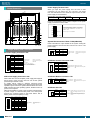
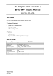
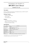
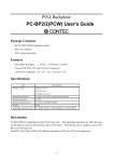
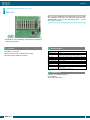
Ver.1.10
10 Slots Backplane for PCI (PCI x 10)
BPC-1111
BPC-1111 is the Backplane board which have the 10 PCI slots.
The Backplane board have one SBC(CPU board) PCI Bus
slots(PCI0(SBC)) and nine PCI Bus slots(P_PCI1 - P_PCI2
and S_PCI1 - S_PCI7).
* Specifications, color and design of the products are subject to
change without notice.
Features
Specifications
1PCI(SBC) + 9 PCI slots
Support for ATX and AT compliant power supply.
The optional unit suitable for mounting.
Item
Specification
Correspondence bus
PCI Bus
Number of slots *1
SBC(CPU board) PCI bus slot PCI0(CPU) x 1 *1
PCI bus slot (P_PCI1 - P_PCI2 & S_PCI1 - S_PCI7 ) x 9
+5VDC, -5VDC, +12VDC, -12VDC, + 3.3VDC (Only for ATX power)
Supply power
Operating conditions
0 - 60 °C , 10 - 90% RH(No condensation)
Storage conditions
-20 - 70 °C
Floating dust particles
Not to be excessive
Corrosive gases
None
Major dimensions (mm)
245.1(W) x 210.0(D)
Weight
375g
Installable chassis
*1
FA-UNIT-F11BE, FA-UNIT-M11BE, FA-UNIT-M11RFV,
FA-UNIT-F11RFV
The SBC(CPU board) must install it to the PCI0(CPU) slot.
Packing List
The BPC-1111 Backplane Board
User's Manual
ATX Control 6pin Cable
BPC-1111
1
Ver.1.10
Power Supply Terminal: CN3
Board Dimension
245.1
236.2
215.9
210.5
Specification of Power Supply Terminal
41.3
10.2
12.7
33.0
23.1
15.2
139.7
94.0
78.7
73.7
When you input the power supply from the CN1 or CN2
connectors, you can output +5V, -5V, +12V and –12V power
from the CN3 terminal. The maximum output current of each
power supply is showed bellow.
CN1
Voltage
+5VDC
+12VDC
-5VDC
-12VDC
Max. Current
2A
2A
2A
2A
However, the maximum supply current is depend on the power
supply connected to CN1 or CN2.
CN3
165.1
142.3
+5V
Suitable Ring Tongue : WS0.5-3 (correspond)
Suitable Spade Tongue : WS0.5-3A (correspond)
Applicable Wire AWG#(mm2) : 26 - 22(0.2 - 0.5)
Maker : JST
-5V
CN2
210.0
201.9
+12V
CN3
Screw torque : 0.4N-m(Max.)
6.35±0.05
-12V
GND
3.63
[mm]
FAN1
FAN2
CN6
System FAN Connector: FAN1 / FAN2(CN5/CN4)
JP3
[mm]
CN7
Jumper Setting and Connectors
Function
1
Power Good
CN1
1
2
+5V
3
+12V
4
-12V
5
GND
6
GND
7
GND
8
GND
9
-5V
10
+5V
11
+5V
12
+5V
Suitable Housing
Suitable Contact
Maker
: GTC6P-1(correspond)
: PCK18-2TR9(correspond)
: BURNDY
Option Cable
(One side is solder disposal.)
Model
: PCA-6P2 CONTEC
Cable length 36cm(AWG#18), two
ATX Power Supply Connector: CN2
CN2
20
Pin No.
Function
Pin No.
Function
11
+3.3V
1
+3.3V
12
-12V
2
+3.3V
13
GND
3
GND
14
PON
4
+5V
15
GND
5
GND
16
GND
6
+5V
17
GND
7
GND
18
-5V
8
Power Good
19
+5V
9
+5VSBY
20
+5V
10
+12V
1
10
BPC-1111
Suitable Housing
Suitable Contact
Maker
Pin No.
Function
1
N.C.
2
+12V
3
GND
Suitable Housing
Suitable COntact
Maker
: 22-01-1034 (correspond)
: 08-70-0057 (correspond)
: Molex
ATX Power Control Connector: CN6
CN6
1
2
3
4
5
6
Pin No.
Function
1
PME#
2
GND
3
PBTN-IN
4
GND
5
PSOUT
6
+5V SBY
Suitable Housing: XHP-6 (correspond)
Suitable Contact : SXH-001T-P0.6 (correspond)
Maker
: JST
ATX Power Button connector: CN7
When used with an ATX-compliant power supply that supports
remote power on/off, the CPU card can turn off the system
power through software control.
To enable soft-off control in software, advanced power
management must be enabled in the Setup program and in the
operation system. When the system BIOS receives the correct
APM command from the operating system, the BIOS turns off
power to the computer.
With soft-off enabled, if power to the computer is interrupted by
a power outage or a disconnected power cord, when power
resumes, the computer returns to the power state it was in
before power was interrupted (on or off).
11
CN4 / CN5
1
2
3
AT Power Supply Connector: CN1
Pin No.
FAN1 and FAN2 are 3-pins header for the system cooling fan
power connector. The fan must be a 12V fan. Pin 2 is for +12V
power supply.
CN7
2
1
Pin No.
Function
2
GND
1
PBTN
Suitable Housing : XHP-2 (correspond)
Suitable Contact : SXH-001T-P0.6 (conrrespond)
Maker
: JST
ATX Power ON: JP3
JP3
3
2
1
Pin No.
Function
3
GND
2
PBIN
1
PSOUT
2-3 Short : Disable ATX power control and set the
ATX Power Supply ON always by push
switch
(use as AT Power Supply).(Default))
1- 2 Short : Enable ATX Power Control by push
switch
: 39-01-2200 (correpond)
: 5556 (correspond)
: Molex
2