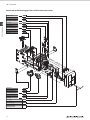
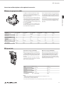
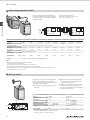
1
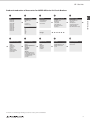
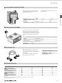
SAE – Base Units Product Skeleton of Accessories for SUPER AE Series Air Circuit Breakers SAE – Base Units 1 Mitsubishi Electric offers a wide range of accessories for the Air Circuit Breakers to serve almost all variations of applications. Position 1 2 3 4 5 6 7 8 9 10 11 4 Name Air circuit breaker Cradle CC-Link® Interface unit PROFIBUS-DP Interface unit MODBUS® Interface unit I/O unit Extension module ETR unit Main setting module Optional setting module Door frame (DF) Position 12 13 14 15 16 17 18 19 20 21 22 Name Dust cover (DUC) Push button cover (BC-L) Auxiliary switch standard (AX) Auxiliary switch high capacity type (HAX) Shunt trip device (SHT) Closing coil (CC) Under voltage trip device (UVT) Trip coil (TC (OCR-Alarm)) UVT-controller (U-CON) Condenser trip device (COT) Motor charging device (MD) Position 23 24 25 26 27 28 29 30 31 32 Name Counter (CNT) Cylinder lock (CYL) Door interlock (DI) Mechanical interlock (MI) Safety shutters (SST) Safety shutter lock ( SST-LOCK) Cell switch (CL) Interphase Barrier (BA) Horizontal terminal Vertical terminal SAE – Base Units Product Introduction of Accessories for SUPER AE Series Air Circuit Breakers Type AE1000-SW AE1250-SW AE1600-SW AE2000-SWA AE2000-SW AE2500-SW AE3200-SW AE4000-SWA AE4000-SW AE5000-SW AE6300-SW 2 à Approvals LR GL BV DNV ABS NK 6 Mechanical accessories Push button cover Counter Cylinder lock Terminal cover Door frame Dust cover Interphase barrier Mechanical interlock Door interlock Technical standards IEC 60947-2 EN 60947-2 (CE) VDE JIS C 8201-2-1 GB 14048.2 (CCC) 3 Fixed type 7 Electronic trip relay General use WS type Generator protection use WM type On request: Special use WB type Optional G1: Ground fault protection E1: Earth leakage protection AP: 2nd Additional Pre-alarm N5: Neutral pole 50 % protection Connection Drawout type Horizontal terminal Vertical terminal Front terminal 4 Electrical accessories Auxiliary switch Motor charging device Closing coil Shunt trip device Under voltage trip device Condenser trip device Trip Coil Man./Aut. Reset Type 1 à 8 Relay accessories Extension module Display MCR switch Neutral CT External ZCT VT-W unit Drawout type accessories Cell switch Shorting b-contact Lifting hooks Safety shutter Safety shutter lock Mis-insertion preventor Test jumper 5 9 Network CC-Link® Interface unit PROFIBUS/DP Interface unit MODBUS® Interface unit I/O unit J Special environment Moisture-fungus treatment Corrosion resist For details on our full range including accessories contact your local distributor 5 SAE – Base Units 1 SAE – Base Units Specifications SAE – Base Units 1 SUPER AE – WORLD SUPER SERIES Breaker type AE 1000- SW AE 1250- SW AE 1600 -SW AE 2000- SWA 1000 1250 1600 2000 Frame size A Rated insulation voltage (AC V) 50/60 Hz Ui 1000 Ue 690 Uimp 12 Rated operating voltage (AC V) 50/60 Hz Rated impulse withstand voltage (kV) Pollution degree 3 Number of poles P Rated current In (CT rating) Adjustment range Rated current (A) Ir General use (current rating adjustable 0.5 to 1.0 x In 0.05 step) Generator protection (current rating fixed) Rated current of neutral pole (A) Ultimate breaking capacity Icu (kA rms) 4 3 4 1250 625-687.5-750-812.5875-937.5-1000-1062.5-11251187.5-1250 1600 800-880-960-10401120-1200-1280-13601440-1520-1600 2000 1000-1100-1200-13001400-1500-1600-17001800-1900-2000 400 ≤ Ir ≤ 1000 800 ≤ Ir ≤ 1250 1000 ≤ Ir ≤ 1600 1250 ≤ Ir ≤ 2000 1600 2000 65 65 65 600 V AC 65 65 65 65 240 – 500 V AC 65 65 65 65 690 V AC 65 65 65 65 600 V AC 65 65 65 65 240 – 500 V AC 65 65 65 65 690 V AC 25 a 25 a 25 a 25 a 500 V AC 25 a 25 a 25 a 25 a 690 V AC 143 143 143 143 600 V AC 143 143 143 143 143 143 143 143 690 V AC 143 143 143 143 600 V AC 143 143 143 143 240 – 500 V AC 143 143 143 143 690 V AC 52.5 52.5 52.5 52.5 500 V AC 52.5 v 52.5 v 52.5 v 52.5 v 1s 65 65 65 65 2s 60 60 60 60 3s 50 50 50 50 40 f 40 f 40 f 40 f Without instantaneous Rated service breaking capacity Ics (kA rms) % lcu Rated making capacity Icm (kA, peak) Disconnector: switching capacity (6 x Ir at 690V AC) Rated short time withstand current (kA rms) ICW Maximum total breaking time (ms) Closing time Number of operating cycles (ON/OFF) (ms) With rated current 500 V AC In 690 V AC In Without rated current Horizontal terminal Connecting terminal Vertical terminal Front terminal Fixed type Dimensions (H x W x D mm) Drawout type Fixed type Drawout type (with cradle) Cradle only 80 80 80 80 5000 5000 5000 1500 5000 5000 5000 1500 25000 v 25000 v 25000 v 25000 d v v v — vc v v v — 3-pole 410 x 340 x 290 4-pole 410 x 425 x 290 3-pole 430 x 300 x 368 4-pole 430 x 385 x 368 3-pole 41 41 42 47 4-pole 51 51 52 57 3-pole 64 64 65 70 4-pole 78 78 79 84 3-pole 26 26 26 31 4-pole 30 30 30 35 The columns for "without instantaneous" are the values when the bare main body and the external relay is combined. The number of operating cycles without rated current also include the number of operating cycles with rated current. c AE4000-SW, AE5000-SW, AE6300-SW, AE2000-SWA and AE4000-SWA apply for only vertical terminal of connecting terminal. d This value means number of operating cycles of ACB's body not including accessories. e Products with low rating types is available. 6 3 1000 500-550-600-650700-750-800-850900-950 -1000 1250 Without instantaneous b 4 65 With MCR a 3 1000 240 – 500 V AC Weight (kg) 4 690 V AC With MCR IEC 60947-2, EN 60947-2, VDE, JIS C 8201-2-1 3 SAE – Base Units AE 2500- SW AE 3200- SW AE 4000- SWA AE 4000- SW AE 5000- SW AE 6300- SW 2000 2500 3200 4000 4000 5000 6300 1000 1000 690 690 12 12 3 3 4 3 4 1 SAE – Base Units AE 2000- SW 3 3 4 3 4 3 4(HN, FN) g 3 4(HN, FN) g 3 4(HN, FN) g 2000 1000-1100-1200-13001400-1500-1600-17001800-1900-2000 e 2500 1250-1375-1500-16251750-1875-2000-21252250-2375-2500 3200 1600-1760-1920-20802240-2400-2560-27202880-3040-3200 4000 2000-2200-2400-26002800-3000-3200-34003600-3800-4000 4000 2000-2200-2400-26002800-3000-3200-34003600-3800-4000 5000 2500-2750-3000-32503500-3750-4000-42504500-4750-5000 6300 3150-3465-3780-40954410-4725-5040-53555670-5985-6300 800 ≤ Ir ≤ 2000 1600 ≤ Ir ≤ 2500 2000 ≤ Ir ≤ 3200 2500 ≤ Ir ≤ 4000 2500 ≤ Ir ≤ 4000 3150 ≤ Ir ≤ 5000 4000 ≤ Ir ≤ 6300 2000 2500 3200 4000 2000 (4000) h 2500 (5000) h 3150 (6300) h 75 75 75 75 85 85 85 75 75 75 75 85 85 85 85 85 85 85 130 130 130 75 75 75 75 85 85 85 75 75 75 75 85 85 85 75 75 75 75 100 100 100 45 a 45 a 45 a 45 a 65 a 65 a 65 a 45 a 45 a 45 a 45 a 65 a 65 a 65 a 100% 100% 165 165 165 165 187 187 165 165 165 165 187 187 187 187 187 187 187 187 286 286 286 165 165 165 165 187 187 187 165 165 165 165 187 187 187 165 165 165 165 220 220 220 94.5 94.5 94.5 94.5 143 143 143 94.5 v 94.5 v 94.5 v 94.5 v 143 v 143 v 143 v 75 75 75 75 100 100 100 75 75 75 75 85 85 85 65 65 65 65 85 85 85 40 f 40 f 40 f 40 f 50 f 50 f 50 f 80 80 80 80 80 80 80 1500 1500 1000 500 1000 1000 1000 1500 1500 1000 500 1000 1000 1000 20000 v 20000 v 20000 v 20000 10000 (3P) / 5000 (4P) 10000 (3P) / 5000 (4P) 10000 (3P) / 5000 (4P) v v v — vc — vc — vc — vc v v v — — — — 410 x 475 x 290 414 x 873 x 290 410 x 605 x 290 414 x 1003 (1133) x 290 h 430 x 435 x 368 430 x 439 x 368 480 x 875 x 368 430 x 565 x 368 430 x 569 x 368 480 x 1005 (1135) x 368 h 60 368 61 368 63 81 160 160 160 72 75 73 99 75 99 180 (200) h 180 (200) h 180 (200) h 92 78 93 103 95 108 233 233 240 113 116 114 136 116 136 256 (279) h 256 (279) h 263 (286) h 35 119 35 140 35 49 118 118 125 43 44 43 61 43 61 133 (148) h 133 (148) h 140 (155) h f This value means the instantaneous breaking time at short-circuit interruption. As for accessories (SHT, UVT) refer to page 12 and 13. 4 (HN) means the neutral poles current capacity is 50% of the rated current, for 4-poles. 4 (FN) means the neutral poles current capacity is 100% of the rated current, for 4-poles. h () shows the value for 4P FN type. Remarks: – All models conform the isolating function according to IEC 60947-2. – Reverse connection is possible g 7 SAE – Base Units Connections SAE – Base Units 1 Connection arrangements The following connecting methods are available for the AE1000-SW – AE3200-SW. Connection Horizontal connection Mounting method Standard Vertical connection Front connection Vertical terminal adapter Front terminal adapter Optional Optional Accessory Optional Fixed type — — (Standard) (FIX-VTA) (FIX-FTA) (DR-VTA) Available as accessory (refer to page 15) (DR-FTA) Optional accessory (on request) Drawout type (Standard) Standard equipment (shipping version) Remark (DR-VT) Special equipment (on request) (DR-FT) Special equipment (on request) Connection image: AE1000 – 1600-SW, 3-pole type Standard Fixed type breakers AE1000/1250/1600/2000/2500/3200-SW are also available as Drawout type. Please order the corresponding cradle with the drawout mechanism (see table on next page) The following connecting methods are available for the AE2000-SWA, AE4000-SWA and AE4000-SW – AE6300-SW. Connection Vertical connection Mounting method Standard Fixed type (FIX-VT) Drawout type (DR-VT) Special equipment (on request) Remark Connection image: AE2000-SWA, 3-pole type For AE2000-SWA, AE4000-SWA, AE4000-SW, AE5000-SW and AE6300-SW models, vertical terminal only is available. Available Connections Breakers A1000-SW AE1250-SW AE1600-SW AE2000-SWA AE2000-SW AE2500-SW AE3200-SW AE4000-SWA AE4000-SW AE5000-SW AE6300-SW Horizontal U U U U U — u — u — u — u — U — U — U — — u — U FIX-VTA — u — U U FIX-VT — — — — FIX-FTA u u u — u u u — — — — Horizontal U U U U U U DR-VT u u u — U u u u — U — U — U — U u u u — u u u — — — — u u u — u u u — — — — u u u — u u u — — — — Connections Fixed type (FIX) Drawout type DR-FT (DR) DR-VTA DR-FTA V Standard 8 v Option — Not available SAE – Base Units Order information – Air circuit breakers Standard series AE-SW – Fixed type Base unit equipment 3-pole type Art. no. 4-pole type Art. no. AE1000-SW AE1000-SW 3P Fix, ETRBASE-P3, AX10 168373 AE1000-SW 4P Fix, ETRBASE-P3, AX10 168434 AE1250-SW AE1250-SW 3P Fix, ETRBASE-P3, AX10 168435 AE1250-SW 4P Fix, ETRBASE-P3, AX10 168436 AE1600-SW AE1600-SW 3P Fix, ETRBASE-P3, AX10 168437 AE1600-SW 4P Fix, ETRBASE-P3, AX10 168438 Further elements that must be ordered: v Main setting module for protection v Accessories as required AE2000-SW AE2000-SW 3P Fix, ETRBASE-P3, AX10 168443 AE2000-SW 4P Fix, ETRBASE-P3, AX10 168444 AE2500-SW AE2500-SW 3P Fix, ETRBASE-P3, AX10 168445 AE2500-SW 4P Fix, ETRBASE-P3, AX10 168446 AE3200-SW AE3200-SW 3P Fix, ETRBASE-P3, AX10 168447 AE3200-SW 4P Fix, ETRBASE-P3, AX10 168448 1 SAE – Base Units Breaker Shipping contents: V Electronic trip Relay base unit V Power supply PW3 V10 auxiliary contacts (5 NO, 5 NC contacts) V Automatic reset type trip coil (TCA-AL-W) Cradle with the drawout mechanism Cradle For type Art. no. CRD163-W Draw Out type AE1000-AE1600 3P 170078 CRD164-W Draw Out type AE1000-AE1600 4P 170079 CRD323-W Draw Out type AE2000-AE3200 3P 170080 CRD324-W Draw Out type AE2000-AE3200 4P 170081 REC-FD-W Drawout mechanism with drawout handle 169004 Air circuit breaker series AE-SWA Base unit equipment Shipping contents: V Electronic trip Relay base unit V Power supply PW3 V10 auxiliary contacts (5 NO, 5 NC contacts) V Automatic reset type trip coil (TCA-AL-W) Breaker Fixed type Art. no. Draw-out type Art. no. AE2000-SWA AE2000-SWA 3P Fix, ETRBASE-P3, AX10 168439 AE2000-SWA 3P D/O, ETRBASE-P3, AX10 168441 AE2000-SWA AE2000-SWA 4P Fix, ETRBASE-P3, AX10 168440 AE2000-SWA 4P D/O, ETRBASE-P3, AX10 168442 AE4000-SWA AE4000-SWA 3P Fix, ETRBASE-P3, AX10 168449 AE4000-SWA 3P D/O, ETRBASE-P3, AX10 168451 AE4000-SWA AE4000-SWA 4P Fix, ETRBASE-P3, AX10 168450 AE4000-SWA 4P D/O, ETRBASE-P3, AX10 168452 Further elements that must be ordered: v Main setting module for protection v Accessories as required Air circuit breaker series AE4000 – 6300-SW – Fixed / Drawout type Base unit equipment Shipping contents: V Electronic trip Relay base unit V Power supply PW3 V10 auxiliary contacts (5 NO, 5 NC contacts) V Automatic reset type trip coil (TCA-AL-W) Further elements that must be ordered: v Main setting module for protection v Accessories as required Breaker Fixed type 3/4-pole Art. no. Draw-out type 3/4-pole Art. no. AE4000-SW AE4000-SW 3P Fix, ETRBASE-P3, AX10 205144 AE4000-SW 3P D/O, ETRBASE-P3, AX10 205153 AE5000-SW AE5000-SW 3P Fix, ETRBASE-P3, AX10 205145 AE5000-SW 3P D/O, ETRBASE-P3, AX10 205154 AE6300-SW AE6300-SW 3P Fix, ETRBASE-P3, AX10 205146 AE6300-SW 3P D/O, ETRBASE-P3, AX10 205155 AE4000-SW HN AE4000-SW HN 4P Fix, ETRBASE-P3, AX10 205147 AE4000-SW HN 4P D/O, ETRBASE-P3, AX10 205156 AE4000-SW FN AE4000-SW FN 4P Fix, ETRBASE-P3, AX10 205148 AE4000-SW FN 4P D/O, ETRBASE-P3, AX10 205157 AE5000-SW HN AE5000-SW HN 4P Fix, ETRBASE-P3, AX10 205149 AE5000-SW HN 4P D/O, ETRBASE-P3, AX10 205158 AE5000-SW FN AE5000-SW FN 4P Fix, ETRBASE-P3, AX10 205150 AE5000-SW FN 4P D/O, ETRBASE-P3, AX10 205159 AE6300-SW HN AE6300-SW HN 4P Fix, ETRBASE-P3, AX10 205151 AE6300-SW HN 4P D/O, ETRBASE-P3, AX10 205160 AE6300-SW FN AE6300-SW FN 4P Fix, ETRBASE-P3, AX10 205152 AE6300-SW FN 4P D/O, ETRBASE-P3, AX10 205161 3-pole type Art. no. 4-pole type Art. no. Switch-disconnector AE-SW – Fixed / Drawout type Base unit equipment Shipping contents: V 10 auxiliary contacts (5 NO, 5 NC contacts) V Switching capacity IR x 6 Further elements that must be ordered: v Accessories as required Breaker AE1000-SW AE1000-SW 3P Fix, Bare, AX10 193919 AE1000-SW 4P Fix, Bare, AX10 193920 AE1250-SW AE1250-SW 3P Fix, Bare, AX10 193921 AE1250-SW 4P Fix, Bare, AX10 193922 AE1600-SW AE1600-SW 3P Fix, Bare, AX10 193923 AE1600-SW 4P Fix, Bare, AX10 193924 AE2000-SW AE2000-SW 3P Fix, Bare, AX10 193929 AE2000-SW 4P Fix, Bare, AX10 193930 AE2500-SW AE2500-SW 3P Fix, Bare, AX10 193931 AE2500-SW 4P Fix, Bare, AX10 193932 AE3200-SW AE3200-SW 3P Fix, Bare, AX10 193933 AE3200-SW 4P Fix, Bare, AX10 193934 AE2000-SWA AE2000-SWA 3P Fix, Bare, AX10 193925 AE2000-SWA 4P Fix, Bare, AX10 193926 AE4000-SWA AE4000-SWA 3P Fix, Bare, AX10 193935 AE4000-SWA 4P Fix, Bare, AX10 193936 AE2000-SWA AE2000-SWA 3P D/O, Bare, AX10 193927 AE2000-SWA 4P D/O, Bare, AX10 193928 AE4000-SWA AE4000-SWA 3P D/O, Bare, AX10 193937 AE4000-SWA 4P D/O, Bare, AX10 193938 9 SAE – Accessories Overview and mounting positions of the main accessories SAE – Accessories 2 Auxiliary switch AX Page13 Counter CNT Page 13 Under voltage trip device UVT Page 12 Closing coil CC Page 12 Shunt trip device SHT Page 13 Mis insertion preventer MIP Page 15 Safety shutters SST Page 14 Cell switch CL Page 14 P1 HID BIS SU MIT CR M 68 6422412 INS 10 8T 16 12 )= 10 16 0) 1 Ii(xIr60 Ir0(A P1E M W 25304 ILx.2 TNY U18000 151.1.2 15 20 ) R .4601.1.515. 0 0T.1L.0(s 6.060.10.3 ERR% I2tFM .5Ir44).5500..53 )0.5O LIL 2.5IL33(x F PAL (s sAR I2tTdN ILTdLSI1.52 dIr)(O L A IP IsI2 .1015 ItTsLIdi Isx TR (IxpL)TA .3.15.10.00.3.5 E 0.50.7 00.8.05 1.50.8 G I1g0.10.3 10.0.91.53.0Tg3).0 (s TYP FgxIn)( 2REETS T RNU GRT Ig .8.941.0 TRL/S )OSC K VE(LE S.7T6 O TE .68Ip Lifting hooks HP Motor charging device MD Page 11 Under voltage trip device UVT Page 12 Cylinder lock CYL Page 14 Castell lock CAL Page 14 Power supply Page 19 Electronic trip relay Page 20 Drawout mechanism with drawout handle Page 9 10 (optional) SAE – Accessories Overview and description on the optional accessories Motor charging device (MD) If the closing spring is to be charged automatically whenever the breaker is opened, then this can be done through an additional auxiliary contact (AXb) (OFF charging method). As soon as charging is completed, a visual display on the front says “CHARGED”. There is always the option of manual operation in an emergency. A closing coil (CC) is required for closing the breaker by remote control, and a shunt trip device (SHT) is required for opening it in this way. This warrants the prevention of pumping, both electronically and mechanically. The circuit of the motor is separate from the ON/OFF circuit (CC, SHT). The “CHARGED” signal is also available via the 413 (TS+) and 414 (TS-) terminals (included in the standard MD configuration). Specifications Rated voltage Applicable voltage range MD-AD125-W 100 – 125 V AC/DC (V) 85 – 137.5 MD-AD250-W 200– 250 V AC/DC 170 – 275 Applied voltage (V) 100 / 125 200 / 250 Inrush current (peak value) (A) 10 / 12 5/6 Steady current Charging time Criterion for power requirement Order information MD-AD125-4A4W-W 100 – 125 V AC/DC 85 – 137.5 100 / 125 MD-AD250-4A4W-W 200– 250 V AC/DC 170 – 275 MD-DO24-W 24 V DC 18 – 26.4 MD-DO48-W 48 V DC 36 – 52.8 200 / 250 24 V 48 V 7/8 22 14 2 6 3 ≤5 ≤5 ≤5 (A) 3 (sec) ≤5 1 ≤5 10 / 12 12 4 ≤5 (VA) 700 / 1000 700 / 1000 700 / 1000 700 / 1000 500 500 168515 168516 168517 168518 168519 Art. no. 168514 Trip coil (AL) Automatic reset type (TCA-AL-W) Manual reset type (TCM-AL-W) OCR alarm (AL) is provided as standard if ETR is equipped. OCR alarm (AL) is the contact (1a) of short-time operation (30 ms), being output when the breaker is tripped by the electronic trip relay. On the manual reset type (optional), the gray manual reset button will stick out to continuously output OCR alarm (AL) if the breaker is tripped by the electronic trip relay. After tripping, the breaker can not be turned on unless the manual reset button on the front side of the breaker is pressed for resetting. Two types of automatic reset type (standard) and manual reset type (optional) are available. When ordering, specify either. Specifications Voltage Resistive load Inductive load Order information AC (V) DC (V) AC (A) DC (A) AC (A) DC (A) TCA-AL-W 125 / 240 30 / 125 / 240 5/3 4 / 0.4 / 0.2 3/2 3 / 0.4 / 0.2 Art. no. 168535 (standard) TCM-AL-W 125 / 240 30 / 125 / 240 5/3 4 / 0.4 / 0.2 3/2 3 / 0.4 / 0.2 168536 Notes: – Though the control power supply is unnecessary to activate OCR alarm (AL), the self-holding circuit is necessary since the contact output is activated for the short time (30 ms). – This works when tripping occurs in LTD, STD, INST, GFR or ER. – If any continuous output of OCR alarm (AL) is necessary, use the trip indicator (TI) output contact of the electronic trip relay. 11 2 SAE – Accessories In addition to manual operation, the closing spring can be charged automatically by an electric motor every time the breaker is closed (ON charging method). SAE – Accessories Undervoltage trip device (UVT) This is the device that automatically trips the breaker when the circuit voltage drops below the nominal voltage, and comprises a UVT coil and UVT controller. Time range for tripping time: INST (0.2 sec or less)/0.25 sec/0.5 sec/ 0.8 sec/1.0 sec/1.5 sec/3 sec. MITSUBISHI 2 Time delay SAE – Accessories 0.5s or more IN1 D1 Trip button D2 IN2 DT1 max. 2 m UCONDO24B-W INST (V) 24 (DC) — Specifications Rated voltage Frequency UCOND110B-W INST 100–110 (DC) UVT coil UVT controller D2 OUT4 Trip contact UCOND125B-W INST 120–125 (DC) DT2 max. 2 m Breaker UVT coil DT1 min 0.2 sec DT2 Breaker UCOND250B-W INST 220–250 (DC) UCONA120B-W INST 100–120 (AC) 50/60 Hz UCONA240B-W INST 200–240 (AC) UCONA460B-W INST 380–460 (AC) m INST (0.2 sec); m 0.25 sec ; m 0.5 sec ; m 0.8 sec ; m 1.0 sec ; m 1.5 sec ; m 3.0 sec Operating time (time delay) Pick-up voltage Drop-out voltage UCONDO48B-W INST 48 (DC) D1 OUT3 External unit (attached to UVT controller) UVT controller (V) 15.6 – 20.4 (V) 10.8 – 16.8 Trip function 31.2 – 40.8 21.6 – 33.6 65 – 85 45 – 70 78 – 102 54 – 84 143 – 187 99 – 154 65 – 85 45 – 70 130 – 170 90 – 140 247 – 323 171 – 260 203343 203344 203345 203346 203347 203348 With open circuit of DT1, DT2 terminals Power consumption (VA) 20 Order information Art. no. 203341 Accessories 203342 UVT coil: art. no. 168525; UCON label: art. no. 168526 (Packing unit: 10 pcs) Notes: – Please order for each UCON one UVT coil, and for delay setting one UCON lable. – In case of 380–460V AC, the external unit is attached. – The operating time is a guarantee value when it drops from 85 % or more of rated voltage. – Time delay should be allowed for 1.5 s between applying the voltage to the UVT and closing the breaker. – If a remote trip function is required, remove the shorting bar (DT1 – DT2) and connect a normally closed switch, rated 0.5 A at 150 V DC across them. – Usage ambient temperature is a range of max. 40 °C to -5 °C. Closing coil (CC) The closing coil is a device to close the breaker by remote control. Only one closing signal (about 100 msec.) is sent even when the closing coil supply is maintained ON. zz An interlock to prevent pumping is provided electrically. Specifications Rated voltage Applicable voltage range Operating voltage Breaker Breaker CC unit Inrush current A1 Control Control supply supply A2 OneOnepulse circuit Closing time 1 Order information Diode rectifier is not used forforcontrol source Diode rectifier is not used control source 2424 – 48– V48DC.V DC. 1 12 CC-DO48-W (V) 24–48 DC (V) 18–52.8 (V) 24 / 48 AC (A) — (DC 24 V 100 W, DC (A) 3 / 6 DC 48 V 200 W) (sec) max. 0.08 or less Art. no. 168521 In case of double rating of rated voltage, it is the value to the lower rating. Example: In case of DC 24 to 48, it is operating time to DC 24 V. zz Closing time is from the initial energization of the closing coil to the completion of the closing of the main contacts. zz As CC is one-pulse driven, it is not necessary to insert AXb for burning prevention purposes. Inserting AXb will cause anti-pumping function to be ineffective. CC-AD250-W 100–250 AC/DC 75–275 100 / 250 0.7 / 1.7 (AC 100 V 100 VA, AC 250 V 200 VA) 0.8 / 1.8 (DC 100 V 100 W, DC 250 V 200 W) max. 0.08 or less 168520 SAE – Accessories Shunt trip device (SHT) The shunt trip device is used to open the breaker by remote control. A cut-off switch is included (AX /HAX). Inrush current (peak value) Closing time a Breaker Order information Cut-off switch Min. 40 ms SHT unit C1 1 SHT-DO48-W (V) 24–48 DC (V) 16.8–52.8 (V) 24 / 48 SHT-A500-W 380–500 AC 266–550 380–500 0.5 / 0.7 (AC 380 V 250 VA, ( AC 500 V 300VA) AC (A) — W, DC (A) 2.5 / 6.0 (DC 24 VV 100 DC 48 200 W) (sec) max. 0.04 or less Art. no. 168524 max. 0.04 or less SHT-AD250-W 100–250 (AC/DC) 70–275 100 / 250 0.4/ 1.4 (AC 100 V 100 VA, AC 250 V 150 VA) 0.6 / 1.6 (DC 100 V 100 W, DC 250 V 200 W) max. 0.04 or less 168523 168522 — In case of double rating of rated voltage, it is the value to the lower rating. Example: In case of DC 24 to 48, it is operating time to DC 24 V. Control supply C2 SHT Diode rectifier is not used for control source 24 – 48 V DC. Auxiliary switch (AX, HAX) This is the contact that is used to remotely indicate the ON or OFF status of the breaker. zz The a and b contacts may turn simultaneously to ON instantaneously at the time of changing the contact; Pay attention to the contact state when designing circuits. Specifications Load Contact capacity (A) Maximum number of contacts Order information AC 460 V AC 250 V AC 125 V DC 250 V DC 125 V DC 30 V AX-10-W Resistance 5 10 10 0.3 0.6 10 5a5b zz The chattering time at the time of contact ON-OFF is below 0.025 sec. zz For special environment specification, the contact capacity gets deteriorated. Apply for further detail. Inductive 2 10 10 0.3 0.6 6 Art. no. 168962 (standard) HAX-10-W Resistance 5 10 10 3 10 10 5a5b Inductive 2.5 10 10 1.5 6 10 168961 Counter (CNT) This is a mechanical counter which registers the total number of operating cycles (with 1 ON/ OFF switching operation = 1 operating cycle). The number of operating cycles is displayed on the front of the unit. Order information CNT-W Mechanical 5 digits Art. no. 168538 58 02 00 00 Specifications Counter type Display 13 2 SAE – Accessories Specifications Rated voltage Applicable voltage range Operating voltage SAE – Accessories Cell switch (CL) Switch function The cell switches can be set for all the relevant positions, i.e. connected, test and disconnected. Each cell switch consists of 4 individual switches. SAE – Accessories 2 Disconnected Disconnected Disconnected discon. Connected Connected Test test Operation operation CONNECTED CL–C TEST CL-T DISCONNECTED CL-D Cell switch Specifications Load Contact capacity (A) Maximum contacts User's wiring Order information a AC 460 V AC 250 V AC 125 V DC 250 V DC 125 V DC 30 V CL-4-W Resistive 5 10 10 3 10 10 Total 4c BIF-CL-W a Resistive 5 10 10 3 10 10 Inductive 2.5 10 10 1.5 6 10 Art. no. 168512 Inductive 2.5 10 10 1.5 6 10 168575 BIF-CL only necessary for networks operation Interlock device (CYL) The interlock device locks the circuit breaker into the OFF position. There are two locking options available: The relevant key can only be taken out in the OFF position of the circuit breaker, so that it can also be used for unlocking other breakers. zz Castell lock (CAL) a Specifications Interlock Closing Order information a CYL-WK-W Cylinder Basic Art. no. 168539 zz Cylinder lock (CYL) CYL-WK1-W Cylinder 1 CYL-WK2-W Cylinder 2 CYL-WK3-W Cylinder 3 CYL-WK4-W Cylinder 4 CYL-NK-W Castell a Basic 168540 168541 168542 168543 168544 The closing basis for the Castell lock can be designed individually. Further details on request. Safety shutters (SST) The safety shutters cover the main conductors of the cradle side (supply and load side) automatically when the circuit breaker is drawn out. The safety shutters can also be locked with a mechanical locking device (SST LOCK). The padlocks have to be supplied by customer. When checking the main circuit, the safety shutters on the supply and load sides can be opened independently of one another. Specifications Breaker type Number of poles Order information 14 SST-LOCK-W Drawout 3/4 Art. no. 168510 SST-203-W SST-204-W SST-403-W SST-404-W 3 4 3 4 168973 168974 168975 168976 SAE – Accessories Vertical terminal adapter (VTA) To obtain the right draw out configuration, it is extremely important that the breaker unit specifications (type, current rating, optional accessories, etc.) should match the cradle. Specifications Material MIP-W Metal Order information Art. no. 168547 Mis-insertion is prevented by a combination of matching components (on the breaker and the cradle). SAE – Accessories 2 Shorting b-contact (SBC) When moving the breaker from the connected to the test positions, this contact is used to short circuit auxiliary switch (Axb) thus maintaining the correct sequence of operation of the external control circuit. Specifications Number of contacts Application (breaker) Order information SBC-5-W SBC-1-W 1 All breakers Art. no. 168548 SBC-2-W 2 SBC-3-W 3 SBC-4-W 4 SBC-5-W 5 202337 202338 202339 202340 Vertical terminal adapter (VTA) Vertical terminal adapters allow you to turn power connection by 90°. Specifications Application (breaker) Shipping contents Order information For AE2000-SWA, AE4000-SWA, AE4000-SW, AE5000-SW and AE6300-SW models, vertical terminal only is available. VTA-02-W AE1000–AE1600-SW pieces 1 Art. no. 168978 VTA-03-W AE2000–2500-SW 1 VTA-32-W AE3200-SW 1 168979 168980 Front terminal adapter (FTA) Front terminal adapters FTA allows a vertical connection for supply- and load-busbars. Specifications Application (breaker) Pole Typ Shipping contents Order information pieces FTA163F-W AE1000– AE1600-SW 3 Fixed 6 Art. no. 169331 FTA164F-W AE1000– AE1600-SW 4 FTA253F-W AE2000– AE2500-SW 3 FTA254F-W AE2000– AE2500-SW 4 8 6 169332 169333 FTA323F-W FTA324F-W FTA164D-W AE1000– AE1600-SW 4 FTA253D-W AE2000– AE2500-SW 3 FTA254D-W AE2000– AE2500-SW 4 FTA323D-W 3 4 8 FTA163D-W AE3200-SW AE3200-SW AE1000– AE1600-SW 3 4 3 Drawout 6 8 6 8 6 8 6 81 169334 169335 169338 169339 169340 169341 169342 169336 169337 FTA324D-W AE3200-SW AE3200-SW 15 SAE – Accessories Mechanical interlock (MI) 2 This is the device to prevent parallel charge of 2 or 3 units of breakers, and it can interlock the breakers mechanically without fail. All combinations are available among any models from AE1000-SW to AE4000-SWA. zz In case of drawout type,the interlock works at “CONNECTED” position, and in another position the interlock is released, which is convenient for and easy maintenance and inspection of the breaker. Please apply for further details of AE4000-SW to AE6300-SW. zz When to turn OFF one breaker and then turn ON another breakers, please take an interval 0.5 seconds or more. SAE – Accessories Further the interlock is possible among the different connection types or poles, such as fixed type or drawout type, 3 pole or 4 pole. In combination with electric interlock, the higher safety interlock system can be secured. Vertical mounting Horizontal mounting Switching states (for 2 ACBs) 0–12 Type ACB 1 ACB 2 144 1 u u 2 | u Type ACB 1 ACB 2 ACB 3 3 u | 134 ACB2 ACB1 1000 (Max.) 1000 (Max.) 47 zz MI for 3 breakers can not be installed to combine with Door Interlock (DI). 1000 (Max.) Type ACB 1 ACB 2 ACB 3 2 | u u ACB2 Type ACB 1 ACB 2 ACB 3 1 2 3 4 5 6 7 u | u u | | u u u | u | u | u u u | u | | ACB1 ACB2 1 u u u ACB3 ACB2 3 u | u 4 u u | ACB2 1 2 3 4 5 u | u u u u u | u u u u u | | ACB1 ACB2 ACB3 [mm] Specifications Application (breaker) Breaker type Number of poles Order information MI-203F-W MI-204F-W AE1000–1600-SW AE2000-SWA Fixed 3 4 Art. no. 168963 168964 MI-403F-W MI-404F-W AE2000–3200-SW AE4000-SWA 3 4 MI-203D-W MI-204D-W AE1000–1600-SW AE2000-SWA Drawout 3 4 168965 168966 168967 168968 MI-403D-W MI-404D-W AE2000–3200-SW AE4000-SWA 3 4 168969 168970 MI-IW-W Wire set for all mechanical interlock devices required for combination of 3 ACBs 168971 Door interlock (DI) Cabinet door The device has been designed for panel doors with the groove on the left (standard). Locks for grooves on the right are available on request. A wire-type mechanical interlock is used to allow flexibility in positioning breakers in the panel. This mechanical interlock device makes it impossible to open the panel door unless the circuit breaker is not switched off. Specifications Application (breaker) Breaker type Order information 16 DI-F-W For all breakers Fixed Art. no. 168545 Note: When using the door interlock (DI) the application of the mechanical interlock (MI) is not possible. DI-D-W For all breakers Drawout 168546 SAE – Accessories Push button cover (BC-L) This mechanical device can be locked with a padlock or a seal (both is not included in the package) to protect the push buttons of the breaker unit against inadvertent ON/OFF operation. Specifications Material Order information BCL-W Acrylic plate Art. no. 168537 The padlock has to be supplied by the customer. SAE – Accessories 2 Dust cover (DUC) The transparent dust cover is hinged onto the panel door. It has a screw lock and prevents dust and water entering into the circuit breaker. Specifications Material Order information DUC-W IP 54 Art. no. 168960 Terminal cover (TTC) The terminal cover is a transparent cover for safety finger protection of control terminals. Specifications The terminal cover prevents from careless touching to the live control terminals. Protection The TTC-F-W is included within the delivery of a fixed type AE-SW as standard. Application (breaker) Order information TTC-D-W Dawout type IP 20 Art. no. 168549 TTC-F-W Fixed type IP 20 168972 (Standard) Door frame (DF) The door frame improves the appearance, after cutting out the panel door to install the breaker. Details on request. Specifications Application (Breaker) Material Protection Order information DUC-W For all breakers Plastic IP 20 Art. no. 168960 17 SAE – Accessories Current transformer (CT) These current transformers (CT and sensor coil) are suitable for the main conductor and the N conductor. CT-06-W 025 Specifications Rated current IN max b (A) 250 Order information b CT-06-W 050 CT-06-W 063 CT-10-W 100 CT-12-W 125 CT-16-W 160 CT-20-W 125 CT-20-W 160 CT-20-W 200 CT-25-W 250 CT-32-W 320 AE1000-SW AE1000-SW AE1000-SW AE1000-SW AE1000-SW AE1250-SW AE1600-SW AE2000-SW AE2000-SW AE2000-SW AE2500-SW AE3200-SW Application (breaker) a a CT-06-W 031 Art. no. 193939 315 500 630 1000 1250 1600 1250 1600 2000 2500 3200 193940 193941 193942 193943 193944 193945 193946 193947 193948 193949 193950 Shipping contents includs CT and sensor coil for 1 pole. Other transformers on request. At 40 °C and 50/60 Hz Neutral current transformer (NCT) Block diagram with NCT function ACB ACB Alarm Alarm 513 contact contact output 544 The neutral CT is used for ground fault protection when a 3 pole breaker is used on a 3 phase 4 wire system. ETR P1 ETR P2 Control Control supply supply The Ground fault protection module type G1 should be used as optional setting module. N1 output N2 SAE – Accessories 2 Current transformers of type CT-06mmm serve the reduction of IN max. on an AE1000. NCT NCT Specifications Application (breaker) Current range Order information NCT-06 NCT-10 AE630-SW AE1000-SW (A) 630 Art. no. 168986 NCT-16 AE1600-SW AE2000-SW 1600 NCT-20 AE2000-SWA AE2000-SW 2000 AE2500-SW AE3200-SW AE4000-SWA 1000 NCT-12 AE1250-SW AE2000-SW 1250 NCT-25 NCT-32 NCT-40 2500 3200 4000 168987 168988 168989 168990 168991 168992 168993 External current transformer (ZCT/ZT) Transformer ground wire method (ZCT) ACB ACB ETR with ETR with ERER 513 544 Alarm Alarm contact contact output Order information a Further details on request. 18 Z1 P2 with ETRETR with ER ER zz ZCT: three-load phase conductors (and the neutral conductor in a 4-wire system) are passed through the ZCT Z2 Z2 Control supply supply 513 P1 544 P2 Alarm Alarm contact contact output Control Control supply supply zz ZT: The other method uses a smaller ZCT (only supply transformer ground wire passes through to earth. output output Specifications Application Hole diameter for wire a Two methods are available: ZCT ZCT Z1 P1 This option is used to detect several amperes of earth leakage when used in combination with an electronic trip relay that has the earth leakage tripping (ER) option. ACB ACB ZCT ZCT ZCT-163-W Load circuits (mm) 230x60 (oval) Art. no. 168994 ZCT-323-W ZCT-324-W ZT-40B-W ZT-60B-W ZT-80B-W ZT-100B-W 500x108 (oval) ZT-15B-W ZT-30B-W Transformer ground wire Ø 15 Ø 30 370x108 (oval) Ø 40 Ø 60 Ø 80 Ø 100 168995 168996 168997 168999 169000 169001 169002 168998 SAE – Accessories Internal power supply units (PW) Specifications Power supply (V) Output contacts Order information The PW3-W is included as standard power supply in the ACB's. PW3-W 100–240 (AC) 100–125 (DC) 6 PW4-W Art. no. 168985 (standard) 2 PW5-W 24 – 60 (DC) 100 – 240 (DC) 6 6 (SSR) 168562 168563 SAE – Accessories These power supplies are used for supplying the ETR base unit. They are equipped with 6 outputs (alarms and errors). Field test device (Y-2000) The electronic trip relay can be checked by this field test device when the breaker is at test or disconnect position. So it allows you to test the trip relay without the breaker being connected to the main supply. The breaker will trip when tested. HI BISTER SU TES KER MIT EA BR UT TP OU S3 S1 S2 60 50 Hz Hz OP STGNAL SI TC G IN R OC Y NC ST TE IP OP UE ST EQ FR 88 8.8 .8 888.88 88 7 50 UT TP OU S1S2S3 4 IP TR K EC 6 5 VT 1 T 0 SE RE N W DO ST JU L AD GNA SI 3 2 T SE C CH OP ST/OCR a? UP 9 8 TR /60 AL GN SI ? VT 00 20 Y- G IN AT E ER TIM OP T L SE GNA SI Specifications Power supply Test functions Test current signal setting Others Y-2000 100–240 V AC, 50/60 Hz LTD, INST, STD, Ground fault, pre-alarm Continuously variable (10 – 2500 %) Ammeter, time counter T AR ST OP ST Y-2000 Order information Art. no. 27496 Test jumper (TJ) With the breaker taken out of its cradle, this device enables the breaker to be electrically opened and closed, and the operating sequence to be checked. 3 m length of cable is equipped as standard. Other lengths available on request. Specifications Cable length (m) Order information a Test Jumper 3a Art. no. 168977 Other lengths on request Interphase barriers Connections Horizontal (FIX) Vertical terminal (FIX-VT) Fixed type Vertical terminal adaptor (VTA) Front terminal adaptor (FIX-FTA) Horizontal (DR) Vertical terminal (DR-VT) Drawout Front terminal (DR-FT) type Vertical terminal adaptor (VTA) Front terminal adaptor (DR-FTA) AE1000-SW – AE1600-SW l 5 s s l l — s s AE2000-SWA 5 s 5 5 5 s 5 5 5 AE2000-SW – AE3200-SW l 5 s s l s s s s AE4000-SWA 5 s 5 5 5 s 5 5 5 l = Available for the insulation s = Available for separating terminals 5 = Not existing type — = Attachment is impossible For AE4000-SW to AE6300-SW not available 19 SAE – Electronic Trip Relay Introduction and selection Power supply module This module provides control source for Display module, Trip indicator and several indicators (LEDs). (Even when the control power source is off, the function of over current protection and ground fault protection are effective.) The power supply modules provide 6 output contacts for external use (see page 22). 3 Display SAE – Electronic Trip Relay Several measuring data (current, voltage, power etc) and alarms can be displayed with this module. (see page 28) Main setting module Load current LED (standard) This module provides the function of over current protection. It is possible to select the two setting modules according to application (see page 24). This indicator displays the ETR situation (Run or Error) Neutral protection of rated current (100 %) function is standard at 4 pole breaker. RUN LED, ERR. LED (standard) This indicator displays the ETR situation (Run or Error) Pre-alarm (PAL) (standard) This indicator displays the Pre-alarm situation when the setting current exceeds. If a power supply module with alarm contacts is installed, the output contact of Pre-alarm is available. Optional setting module (option) (figure shows G1) *The output is reset when the electric current goes below the set level after an alarm is set off Additional functions and characteristics can be selected by optional setting modules (see page 26). Trip indicator LED (standard) This indicator displays the trip cause. RESET button (standard) TEST terminal (standard) This terminal already installed as standard and is used for checking by the field test device Y-2000. 20 Pre-alarm current level setting dial (standard) For setting the current level for PreAlarm. If current exceeds this level, pre-alarm is indicated. When push this reset button, trip indicator, and Pre-Alarm will be reset. And when the instantaneous test by field test device Y-2000 (optional) and push this reset button, as a result of LTD and STD function become ineffective. SAE – Electronic Trip Relay Standard functions OCR alarm (AL) When it happens to trip by over current, ground fault (GFR) or Earth leakage (ER), this function issues a warning alarm. 3 When harmonics in load current are large, the current on neutral pole exceeding rated current may flow. Harmonics may cause some troubles. SAE – Electronic Trip Relay Neutral pole overcurrent protection (NP) Neutral pole overcurrent protection prevents them by operating at 100% of rated current on neutral pole. Please see page 27 for 50 % neutral protection. Special functions – optional MCR: Making current release Just under the breaker closing operation (from open to close), Instantaneous characteristic become effective, but after closing the breaker, instantaneous characteristic become ineffective. When you order the MCR switch, MCR switch is built in the main body. If MCR switch is built in the main body and the adjust dial of INST/MCR on main setting module is set the MCR position, MCR function become effective (see page 27). NCT Neutral CT is required for Ground fault or Neutral pole protection, when 3 pole breaker is used for 3 phase 4 wires system. (see page 18) ZCT ZCT is required for a few amperes earth leakage protection, and is combining ER plug. (see page 18) 21 SAE – Electronic Trip Relay Characteristic table Overview of tripping characteristics of main setting modules in combination with optional setting modules General protection Main setting module only SAE – Electronic Trip Relay 3 G1 Ground fault E1 Earth leakage N5 Neutral pole 50% protection AP 2nd additional Pre-alarm WS General use LTD+STD+INST/MCR WM Generator protection use LTD+STD+INST/MCR Note: WB type for special use is available on request. Power supply modules Product overview Type P3 Rating 100–240 V AC 100–125 V DC Contact capacity (Type code P3, P4) Alarm output contacts 6 output contacts P4 24–60 V DC 6 output contacts P5 100–240 V AC 6 output contacts (SSR) Voltage (V) AC Note: Over current protection and ground fault protection operates without control power source. DC 240 120 125 30 Resistive load Inductive load cosφ = 4.0 L/R = 7 ms 0.5 A 1A 0.05 A 1A cosφ = 1.0 1A 1A 0.1 A 1A Contact capacity (Type code P5) Factory setting of 6 output contacts is as follows. G1/E1/AP Refer to lower table LTD STD/INST PAL TAL ERR Selfholding Selfholding Non Selfholding Non Selfholding Non Selfholding Type G1 E1 AP TRIP side Selfholding Selfholding — ALARM side Non Selfholding Non Selfholding Non Selfholding Description: Self-holding type: The output condition is held until it is reset. Non self-holding type: The output is reset if it is returned to the normal condition. 22 Voltage (V) AC DC 240 120 125 30 Normal current 0.1 A 0.1 A 0.1 A 0.1 A Peak inrush current 0.3 A 0.3 A 0.3 A 0.3 A ON resistance (max.) 5Ω 5Ω 5Ω 5Ω SAE – Electronic Trip Relay CT rating table AE1000-SW 1000 A 250 A 315 A 500 A 630 A AE1250-SW 1250 A AE1600-SW 1600 A AE2000-SWA 2000 A AE2000-SW 2000 A 1250 A 1600 A AE2500-SW 2500 A AE3200-SW 3200 A AE4000-SWA 4000 A AE4000-SW 4000 A AE5000-SW 5000 A AE6300-SW 6300 A Notes: – AE1000-SW and AE2000-SW has low rating types, too. – As for details of ratings, refer to pages 6 and 7. Electronic trip relay (ETR configuration overview) Additional function M Extension module (EX1) Main setting module WS1, WM1 AE1000–1600-SW, AE2000–3200-SW, AE4000-SW WS2, WM2 AE2000-SWA, AE4000-SWA, AE5000-SW WS3, WM3 AE6300-SW Optional setting module M BIF-CC Power supply P3: AC 100–240 V / DC100–125 V with output contact N5: Neutral pole 50 % protection P4: DC 24–60 V with E1: Earth leakage protection output contact AP: 2nd Additional Pre-alarm P5: DC 100–240 V with output contact (SSR) G1: Ground fault protection Network M Display (DP1) M BIF-PR M Display onto panel board (DP2) M BIF-MD M VT-W unit M MCR switch (MCR-SW) The assignment of the contacts can be changed with DP1/DP2. The output of G1/E1/AP/PAL OUT can also be changed to the self-holding type from the non self-holding type. WS : General use WM: Generator protection use (WB: Special use: on request) 23 SAE – Electronic Trip Relay 3 SAE – Electronic Trip Relay S Types – General Protection Load current LEDs 2 INST/MCR pick-up current Ii setting dial 1 Current Ir setting dial (MCR: option a) 3 3 Uninterrupted current Iu setting dial SAE – Electronic Trip Relay RUN-LED ERR.-LED Pre-alarm LED 4 LTD time Tl setting dial 5 STD time Tsd setting dial 6 STD pick-up current Isd setting dial Trip indicator LEDs (L,S,I) Adjustable setting range No. 1 Setting item Current setting Adjustable setting range Ir 0.5 – 1.0 (0.05 step) x In (CT rating) 3 Uninterrupted current lu 0.8 – 1.0 x Ir (0.02 step), Pick-up current: 1.15 x Iu 4 6 LTD time STD pick-up current TL 12–25–50–100–150 s at Iu x 2 Isd 1.5–2–2.5–3–4–5–6–7–8–9–10 x Ir 5 STD time Tsd Accuracy — 1.05 x Iu…Non Pick-up 1.25 x Iu…Pick-up ± 20% ± 15% 0.5–0.4–0.3–0.2–0.1–0.06 – 0.06–0.1–0.2–0.3–0.4–0.5 s (I² t ON) (I²t OFF) at Isd x 1.5 2 INST/MCR pick-up current AE1000-SW–AE1600-SW AE2000-SW–AE3200-SW AE4000-SW Ii AE2000-SWA, AE4000-SWA AE5000-SW AE6300-SW Pre-alarm current Pre-alarm time a b WS1 WS2 WS3 ± 20% This means, it operates in the range between 0.04 and 0.08 s when the time set at 0.06 s. 16–12–10–8–6–4–2 – 2–4–6–8–10–12–16 x Ir (INST) (MCR) a 12–10–8–6–4–2 – 2–4–6–8–10–12 x Ir (INST) (MCR) a 10–8–6–4–2 – 2–4–6–8–10 x Ir (INST) (MCR) a lp Iu x 0.68 – 1.0 (0.04 step) – OVER Tp 1/2 TL (after 1/2 TL, PAL contact output turns on.) ± 15% 0.5 (I2t ON) WS3: 10 (INST) OVER b — ± 10% ± 20% WS1-W WS2-W WS3-W Main setting Module S type WS1 WS2 WS3 168553 205180 24 150 10 WS2: 12 (INST) Specifications Art. no. 168552 1.0 WS1: 16 (INST) Upper figure and table include optional MCR function. Pre-alarm current "OVER" setting is equal to 1.0. Order information Setting for shipment 1.0 SAE – Electronic Trip Relay M Types – Generator Protection Load current LEDs 1 Rated current Ir 2 INST/MCR pick-up (adjusted and labelled by factory: Fixed) current Ii setting dial (MCR: option a) 3 SAE – Electronic Trip Relay 3 LTD pick-up current IL setting dial RUN-LED ERR.-LED Pre-alarm LED 4 LTD time Tl setting dial 5 STD time Tsd setting dial 6 STD pick-up current Isd setting dial Trip indicator LEDs (L,S,I) Adjustable setting range No. 1 3 4 6 Setting item Current setting ULTD pick-up current LTD time STD pick-up current Ir lL TL Isd 5 STD time Tsd Adjustable setting range 0.63 – 1.0 x In (Adjust by factory: Fixed) 1.0–1.05–1.1–1.15–1.2 x Ir 115–20–25–30–40–60 s at IL x 1.2 1.5–2–2.5–3–3.5–4–4.5–5 x Ir Accuracy — ± 5% ± 20% ± 15% Setting for shipment Specify when ordering 1.0 150 10 0.5–0.4–0.3–0.2–0.1–0.06 – 0.06–0.1–0.2–0.3–0.4–0.5 s (I2 t ON) (I2 t OFF) ± 20% This means, it operates in the range between 0.04 and 0.08 s when the time set at 0.06 s. 0.5 (I²t ON) at Isd x 1.5 2 INST/MCR pick-up current AE1000-SW–AE1600-SW AE2000-SW–AE3200-SW AE4000-SW Ii AE2000-SWA, AE4000-SWA AE5000-SW AE6300-SW Pre-alarm current Pre-alarm time a b WM1 WM2 WM3 16–12–10–8–6–4–2 – 2–4–6–8–10–12–16 x Ir (INST) (MCR) a 12–10–8–6–4–2 – 2–4–6–8–10–12 x Ir (INST) (MCR) a 10–8–6–4–2 – 2–4–6–8–10 x Ir (INST) (MCR) a lp Iu x 0.68 – 1.0 (0.04 step) – OVER Tp 1/2 TL (after 1/2 TL, PAL contact output turns on.) WM1: 16 (INST) ± 15% WM2: 12 (INST) WM3: 10 (INST) OVER b — ± 5% ± 20% Upper figure and table include optional MCR function. Pre-alarm current "OVER" setting is equal to 1.0. Specifications WM1-W WM2-W WM3-W Main setting Module S type WM1 WM2 WM3 168553 205180 Order information Art. no. 168552 Note: WB type for special use is available on request. 25 SAE – Electronic Trip Relay Ground fault protection (GFR) The ground fault protection (GFR) of several hundred amperes is possible. Specifications This function can be selected for trip and alarm (no trip). Power supply is necessary for this function, even if there is not power supply, it can function at 0.2 x In or higher. Order information Optional setting Module G1-W G1 (Ground fault protection module) Art. no. 168558 SAE – Electronic Trip Relay 3 Setting item GFR pick-up current GFR time Adjustable setting range Ig 0.1–0.2–0.3–0.4–0.5–0.6–0.7–0.8–0.9–1.0 x In Tg 3–1.5–0.8–0.5–0.3–0.15–<0.1 – <0.1–0.15–0.3–0.5–0.8–1.5–3 s (at 1.5 x Ig) TRIP ALARM Accuracy ±20% Setting for shipment 1.0 ±20% 3 s (TRIP) 2nd Additional Pre-alarm (AP) The Pre-Alarm (1st) function already installed in standard ETR, the 2nd additional Pre-Alarm function can be installed as option, thereby it is possible to monitor (observer) electric circuit in more detail by 2nd additional Pre-Alarm function. Specifications Optional setting Module Order information AP-W AP (2nd Pre-alarm module) Art. no. 168560 Pre-alarm timing chart Ip Current Ip Current PAL-LED Lighting Blinking ON PAL OUT (contact output) Setting item OFF 1/2 TL Accuracy Setting for shipment 2nd additional Pre-alarm pick-up current x Iu (WS) Ip2 0.5–0.6–0.7–0.8–0.84–0.88–0.92–0.96–1.0 0.5–0.6–0.7–0.8–0.84–0.88–0.92–0.96–1.0 x IL (WM) ±10% (WS) ±5% (WM) 1.0 2nd additional Pre-alarm time Tp2 3–1.5–0.8–0.5–0.3–0.15–<0.1 – <0.1–0.15–0.3–0.5–0.8–1.5–3 s (at 1.5 x Ig) TRIP ALARM ±20% 0.9 x TL 26 Adjustable setting range SAE – Electronic Trip Relay Neutral pole 50% protection (N5) Neutral pole overcurrent protection (operating at 100% of rated current) already installed in standard ETR. TYPE N5 But if you would like to operates at 50% of rated current on neutral pole, neutral pole 50% protection realizes it. RUN Specifications N5-W N5 (Neutrale pole protection module) Optional setting Module Order information Art. no. 168561 Earth leakage protection (ER) By combining the ETR with earth leakage protection (ER) and External ZCT, earth leakage protection is possible. Earth leakage protection, earth leakage tripping and earth leakage alarm can be selected. Control supply is necessary for this function. Setting item ER pick-up current ER time Adjustable setting range Iin 1–2–3–5–10 A Te 3–1.5–0.8–0.5–0.3–0.15–<0.1 – <0.1–0.15–0.3–0.5–0.8–1.5–3 s TRIP ALARM (at 1.5 x Iin) Specifications E1-W E1 (Neutrale pole protection module) Optional setting Module Order information Art. no. 168559 Accuracy Setting for shipment +0% –30% 10 A ±20% 3 s (TRIP) MCR switch (MCS-W) If MCR switch is built in the breaker and the dial for INST/MCR on Main setting module is set to any MCR position, MCR function is operative. Specifications Optional setting Module MCR function: During a closing operation of the breaker, Instantaneous characteristics is operative. And it becomes inoperative when the breaker is in the closed position. Order information MCS-W MCR Art. no. 168570 27 SAE – Electronic Trip Relay 3 SAE – Electronic Trip Relay Extension module (EX1) This is the module that realizes various additional functions combining Display module (DP1/DP2), Interface unit (BIF-CC/ BIF-PR/BIFMD) and VT-W unit. 2 3 4 5 6 7 2 display modules and 1 interface unit can be connected simultaneously by internal communication. zz Various measuring elements, high measuring accuracy ON 1 zz Communication function 8 By adopting high-performance ASIC, various measuring elements (load current, voltage, energy,harmonics, etc.) and high measuring accuracy are realized. SAE – Electronic Trip Relay 3 Setting item Type Order information Adjustable setting range Extension Module Art. no. 168564 Display module (DP1/DP2) MITSUBISHI DP1 This is the module that displays and sets various information, for example, measurement, trip and alarm, setting of output contacts and so on. zz Multi display of measuring element It enables to easily monitor the comparison of each measuring element by multi display (load current 4 phases multi display and voltage multi display) on one screen. zz 2-colours back light zz Graphical display By adopting dot matrix type LCD, graphical display such as bar graph display of load current, harmonic currents and characteristic curve are realized. There are 2 types of this module. One is the ETR attachment type (DP1). Another is the panel attachment type (DP2) and is connected to extension terminals of control circuit by 2 m cable (5 m cable will be available on request). If trip or alarm occurred, back light colour changes from green to red automatically. Spedification Type Order information DP1-W DP2-W Display module for ETR assembly Display module for Panel assembly Art. no. 168565 168566 Notes: – Extension module (EX1) is required. – The VT-W measurement module is required to display the measured data except the electric current. Measurement module (VT-W) The VT-W measurement module enables to measure voltages, powers, energies, harmonic currents and etc. by connecting the ETR with Extension module (EX1). MITSUBISHI Specifications Unit for Order information 28 It is to be placed separatetly outside the the breaker. A connection cable of 2 meters length is included. VT-W U/P/E/cos phi/earth leakage/average measuring/trip history/trip current measuring Art. no. 168567 SAE – Electronic Trip Relay Interface unit (BIF-CC/BIF-PR/BIF-MD) zz Intelligent control by Multi-data communication It comes into being the Intelligent control by Multi-data communication through these interface units to PLC/SCADA, which transfer the measurement information, setting values, error information and trip and alarm information. zz Applicable to various open networks. These units are applicable to various open network systems such as CC-Link®, PROFIBUS/ DP and MODBUS® (RS-485), which can be built in easily. 3 SAE – Electronic Trip Relay These Interface units can expand the future possibility in various communication and Intelligent control.a MELSECNET/10 Example: AE-SW and networks PC with MELSECNET/10interface card MELSEC PLC CC-Link® / PROFIBUS/DP / MODBUS® I/O unit MELSEC PLC Eco Monitor Pro ME96NSR MDU AE-SW Specifications BIF-CC-W BIF-PR-W BIF-MD-W Main setting Module S type CC-Link network PROFIBUS/DP network Modbus network 168572 168573 Order information Art. no. 168571 Note: – Extension module (EX1) is required. – The VT-W unit is required to display the measured data except the electric current. I/O unit (BIF-CON/BIF-CL) The input & output controlling unit BIF-CON is available for the remote controlling and remote monitoring of the breaker condition through the various network systems. or Spring-charging.Further, by combining the drawout position switch (BIF-CL), the monitoring of drawout position become available in case of the breaker drawout type. With this BIF-CON in addition to the interface unit, it become possible to control the breaker remotely, like a ON or OFF operations Function Description Breaker ON operation Control Breaker OFF operation Spring charge Monitor Note 1 a contact for CC 1 a contact for SHT (not applicable for AC 380 – 500 V rating) 1 a contact for MD In of BIF-CC and BIF-MD, max.3 contacts monitoring are available. Digital Input (DI) monitoring In case case of BIF-PR, 1 contact monitoring is available. Breaker drawout position Position: CONNECTED, TEST and DISCONNECTED BIF-CL is required. Specifications Application Order information BIF-CON-W I/O unit network module Art. no. 168574 29 SAE – Electronic Trip Relay Configuration table of ETR with EX1 and VT-W module Combination sample Display module + Extension module Type 1 Main setting module 2 Optional setting module 1 = EX1 2 = DP1 – 3 = DP2 WS NP AP Display module + Extension module + VT-W unit 1 = EX1 1 WM G1 E1 NP AP G1 E1 NP AP WM G1 P3 – P5 3 Power supply 2 = DP1 – 3 = DP2,VT-W 1 WS E1 NP AP G1 E1 — — u P3 – P5 Measurement Load current (±2.5 %) Leakage current (±15 %) 3 SAE – Electronic Trip Relay 3 u — — — Voltage (±2.5 %) u — u — — u — — — — u — u Power (active, reactive, apparent) (±2.5 %) — u Power factor (±5 %) — u Energy (active, reactive) (±2.5 %) — u Harmonics current (±2.5 %) — u (3.5 ... 19th) Frequency (±2.5 %) — u Trip history LTD u u u STD u u u INST u u u GFR — — u ER — — — — u UVT u — — u — — — — u — — u — — — — u u2 — — u — — — — u — u — — u2 Alarm history PAL1 PAL2 u — — u — OVER u — — u — — — u — u u GFR — — u — u — u — u — — — — — — — — u — — — u — — — u — EPAL — — — — u ER — — — u — — — u — — — u — — — u Characteristic setting (for panel attachment model DP2 only) LTD u u u STD u u u INST u u u PAL1 u u PAL2 — u GFR — — — u u — — u — — — — U — — — EPAL — — — — U ER — — — u — u — — u — — — — u — — — — — u — — u — — — — U — u — — — — U — — u — — — u Setting Output contacts setting change U U Date & Time U U Demand time U U Alarm holding method U U Trip and alarm information U U Measurement information (min. and max. values) U U u u u u u u u u u u Reset ETR information Main / Optional setting module information Error information CT rating Phase line method Normal connection or reverse connection u: can be displayed by DP1/DP2 2 units of display modules can be attached. 2 Display is available only when UVT module is attached. 3 Included the accuracy of ZCT. 1 30 U: can be displayed and set by DP1/DP2