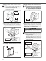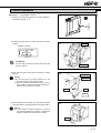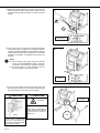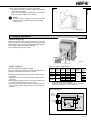
1
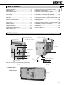
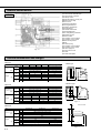
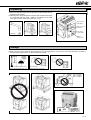
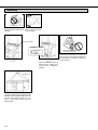
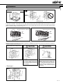
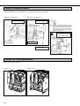
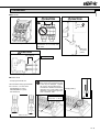
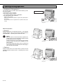
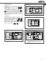
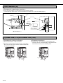
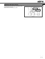
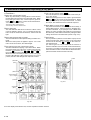
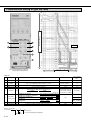
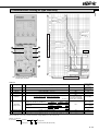
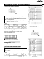
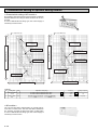
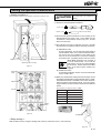
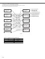
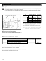
ENGLISH
CHINESE
中文
MITSUBISHI Low-Voltage Air Circuit Breakers series
World Super AE
三菱低压空气断路器 World Super AE
三菱低圧気中遮断器 World Super AE
JAPANESE
Type AE-SW
INSTRUCTION MANUAL
使用说明书
取扱説明書
Types covered in this manual
本手册适用于以下型号产品
対象機種
AE630-SW AE1000-SW AE1250-SW AE1600-SW
AE2000-SWA
AE2000-SW AE2500-SW AE3200-SW
AE4000-SWA
AE4000-SW AE5000-SW AE6300-SW
IMPORTANT NOTE: Before using these Series AE breakers, please read these
instructions carefully, and make sure that all actual users also read them.
重要注释:在使用 AE 断路器系列以前,请务必仔细阅读本说明书,
并确保所有用户也阅读本说明。
ご使用の前に必ずこの取扱説明書をお読みください。
この説明書は、最終ユーザまでお届けください。
07A
Safety precautions
¡Before using this device, make sure to read this Instruction manual thoroughly. The cautionary items noted herein are of
the utmost importance for the safe use of this device, and should always be strictly followed.
¡Please make sure that the final user receives this Instruction manual.
¡This Instruction manual is prepared for an electrical expert.
The following symbols have been used:
DANGER
Failure to follow these instructions may result in dangerous conditions, which in
turn could lead to severe
personal injury or even
death.
CAUTION
Failure to follow these instructions may result in dangerous
conditions, which could result
in moderate to slight personal
injury or damage to equipments and facilities.
Warning for possible electrification under
certain conditions.
This means prohibition. Never ignore this
instruction.
Warning for possible outbreak of a fire
under certain conditions.
Be sure to follow these instructions without fail.
DANGER
¡Do not use this device on the conditions over ratings. Otherwise, ground-fault or short circuit fault could occur due to
dielectric breakdown. Or explosion could occur due to a short circuit protection failure.
¡Do not touch the terminals. There is a risk of electrical shock.
CAUTION
¡A qualified electrician should install this equipment.
¡Inspection and maintenance should be performed by a qualified electrician and only after shutting off the electric power
and verifying that there is no voltage present. Failure to do so could result in an electrical shock.
¡Make sure to tighten the terminal screws to the torque specified in the instruction manual. Failure to do so could result
in fire.
¡Do not install in areas subject to high temperatures, high humidity, dust, corrosive gas, vibrations, or shocks, etc. To do
so could result in malfunction or fire.
¡Install so that trash, concrete dust, iron filings or rainwater cannot get into the circuit breaker unit interior. Failure to do
so could result in malfunction or fire.
¡When the circuit breaker trips automatically, always clear the source of the malfunction before closing the circuit
breaker. Failure to do so could result in fire.
¡Terminal screws should be tightened periodically. Failure to do so could result in fire.
¡Use the breaker in 50/60 Hz. Failure to do so could result in malfunction or fire.
¡Dispose of this product as industrial waste.
E− 2
¡Safety precautions ................................................. 2
¡External view .......................................................... 3
¡Internal construction ............................................... 4
¡Outline dimensions and weight .............................. 4
¡Unpacking .............................................................. 5
¡Storage ................................................................... 5
¡Handling ................................................................. 6
¡Installation .............................................................. 7
¡Mount of drawout handle ........................................ 8
¡Attach the Inter-phase Barrier ................................ 8
¡Connection ............................................................. 9
¡Insert operation .................................................... 11
¡Drawout operation ................................................ 13
¡Charging operation ............................................... 15
¡Opening/Closing operation .................................. 16
¡Door interlock (DI) ................................................ 18
¡Cylinder lock (CYL) and castell lock (CAL) .......... 18
¡Shutter lock (SST-LOCK) ..................................... 18
¡Functions of electronic trip relay parts ................. 20
¡Characteristics setting of type WS relay .............. 22
¡Characteristics setting of type WM relay ............. 23
¡Characteristics setting of type WB relay .............. 24
¡Characteristic setting of optional setting module ... 25
¡Setting the operation characteristics .................... 27
¡Wiring diagram ..................................................... 29
¡Technical note (Arc space, reverse connection) ... 30
¡Technical note (Performance of withstand voltage) ... 30
¡Technical note (Service conditions) ..................... 31
¡Guarantee ............................................................ 31
¡Inspection and maintenance ................................ 32
¡Service network .................................................... 39
External view
< Fixed type >
< Drawout type >
Control circuit terminal box
Electronic trip relay
Control circuit connector
Control circuit terminal box
Arc-extinguish chamber
Cradle
OFF button
Charging
handle
ON buttons
Charging handle
Extension rail
Pad lock hook
Charging
indicator
ON/OFF
indicator
Rated name
plate
Drawout position indicator
Drawout handle aperture
Manual reset button
(option)
Drawout handle
Drawout state
Note: The fixed type is provided with lifting hooks (HP).
Fig. 3-1
Fig. 3-2
< Drawout type >
AE4000-SW∼
AE6300-SW 3P
Fix bolt
Fig. 3-3
E− 3
ENGLISH
Table of contents
Internal construction
1Control circuit terminal block
2Control circuit connector
3Auxiliary switch
4Shunt trip device, closing coil
5Electronic trip relay
6Front cover
7Tripping mechanism
8Closing mechanism
9Charging mechanism
AClosing spring
BDrawout mechanism
CIntermediate base
DArc-extinguishing chamber
EMovable contact
FFixed contact
GConductor on the breaker
HConductor on the cradle
IMain circuit junction
JBase
KContact spring
LConductor on the breaker
MConductor on the cradle
NPower supply CT
OCurrent sensor coil
PCradle
QCradle name plate
AE-SW
Fig. 4-1
Outline dimensions and Weight
Table 4-1
Type
Drawout
type
Fixed
type
Weight
(kg)
Drawout
type
Cradle
only
3P
4P
3P
4P
3P
4P
3P
4P
3P
4P
AE630-SW AE1000-SW AE1250-SW AE1600-SW
340 ✕ 410 ✕ 290 ✕ 40
425 ✕ 410 ✕ 290 ✕ 40
300 ✕ 430 ✕ 368 ✕ 61
385 ✕ 430 ✕ 368 ✕ 61
41
42
40
51
52
50
64
65
63
78
79
77
26
30
AE2000-SWA
340 ✕ 410 ✕ 290 ✕ 108
425 ✕ 410 ✕ 290 ✕ 108
300 ✕ 430 ✕ 368 ✕ 104
385 ✕ 430 ✕ 368 ✕ 104
47
57
70
84
31
35
Type
Fixed
type
Drawout
type
Fixed
type
Weight
(kg)
b
a
Drawout
type
Cradle
only
3P
4P
3P
4P
3P
4P
3P
4P
3P
4P
AE2000-SW
AE2500-SW
AE3200-SW
475 ✕ 410 ✕ 290 ✕ 40
605 ✕ 410 ✕ 290 ✕ 40
435 ✕ 430 ✕ 368 ✕ 61
565 ✕ 430 ✕ 368 ✕ 61
63
61
60
75
73
72
95
93
92
116
114
113
35
36
43
44
AE4000-SWA
475 ✕ 410 ✕ 290 ✕ 117
605 ✕ 410 ✕ 290 ✕ 117
439 ✕ 430 ✕ 368 ✕ 109
569 ✕ 430 ✕ 368 ✕ 109
81
99
108
136
49
61
43
a (MAX)
c
Drawout handle aperture
Fig. 4-3
Drawout
type
Drawout
type
Cradle
only
3P
4P
3P
4P
3P
4P
3P
4P
3P
4P
AE5000-SW
874 ✕ 414 ✕ 290 ✕ 136
1004 (1134) ✕ 414 ✕ 290 ✕ 136
875 ✕ 480 ✕ 368 ✕ 123
1005 (1135) ✕ 480 ✕ 368 ✕ 123
160
180 (200)
233
256 (279)
118
133 (148)
AE6300-SW
Max.173
Fixed
type
Fixed
type
240
263 (286)
125
140 (155)
( ) shows the value for 4P FN type, Neutral pole current capacity is 100% of the rated current.
E− 4
15
Cover position
200
AE4000-SW
(kg)
d
b
Drawout handle
Type
Weight
c
Fig. 4-2
Table 4-3
Dimension
a✕b✕c✕d
(mm)
11
¡Drawout type
Table 4-2
Dimension
a✕b✕c✕d
(mm)
¡Fixed type
40
Dimension
a✕b✕c✕d
(mm)
Fixed
type
169
200
Fig. 4-4
d
ENGLISH
Unpacking
1 Make sure that the packing case is free from any abnormality such as
breaking and/or wetting.
2 Referring to the rating nameplate, make sure that the delivered breaker
is in conformity with your order. Serial No. is indicated on the rated
name plate and the cradle name plate (Fig. 4-1Q).
Fixed type
Drawout type
Accessories
nameplate
ETR accessories
Nameplate
CT rated
name plate
Not attached
Fig. 5-1
Fig. 5-2
Fig. 5-3
Rated
name plate
Fig. 5-4
Storage
✽ When you start using the breaker after storage and if its storage period is over 6 years, use it after lubrication as stated in
“Grease lubricating procedure” for the maintenance manual.
+60°C
–20°C
Average temperature for 24 hours,
however, shall not be higher than 35°C.
Fig. 5-5
Avoid humid air.
Relative humidity : 85% max.
Fig. 5-6
Fig. 5-7
H2S ≤ 0.01ppm
SO2 ≤ 0.05ppm
NH3 ≤ 0.25ppm
Fig. 5-10
OFF
Fig. 5-8
Fig. 5-9
Fig. 5-11
E− 5
Handling
Fig. 6-1
Fig. 6-2
Never drop the breaker when Never roll the breaker
handling.
when handling.
Wire length: 1 m or more
Wire length: 1 m or more
Lifting hooks (HP)
CONNECT position
Fig. 6-5
Fixed type
Drawout type
Fig. 6-3
Fig. 6-4
When the drawout breaker is
lifted with the cradle, lift it
when it is the “CONNECT”
position.
length ≥ 1 m
Fig. 6-6
To lift the breaker types AE4000-SW,
AE5000-SW and AE6300-SW, be sure to
use four ropes with a length of 1 m or
more, or use the lifting truck, apply for
further detail.
E− 6
When lifting and placing, be careful neither to drop nor to impact the breaker and
the terminals for the center of gravity is
by the terminal.
ENGLISH
Installation
< Drawout type >
AE630-SW∼AE4000-SWA
1 mm or less
Tolerance on support flatness ≤ 1 mm
M12
M8
Earthing terminal
Fig. 7-1
Fig. 7-2
In the case of AE4000 ~ 6300-SW, insert four M12 bolts from the bottom and two M12 bolts from the back to mount the
cradle as shown in Fig. 7-3. In the case of 4P FN type, insert six M12 bolts from the bottom and two M12 bolts from the
back to mount the cradle as shown in Fig. 7-4.
AE4000 ~ 6300-SW 3P & 4P (HN)
Cradle
AE4000 ~ 6300-SW 4P (FN)
Mounting angle (Non-magnetic)
Mounting angle (Non-magnetic)
2-M12
2-M12
6-M12
4-M12
Fig. 7-3
Fig. 7-4
Operate the drawout operation (CONNECT position to DRAWOUT position) according to instructions of drawout
operation. (Refer to P.13 and 14.)
Lifting by lifting truck or lifting hooks
CAUTION
CAUTION
Lifting
Support
Falling
Fig. 7-5
When the main body is drawn out,
the center of gravity shifts to the
front. If the cradle is not secured,
take measures against overturning
and dropping.
Fig. 7-6
< Fixed type >
On AE4000-SWA,AE4000-SW ~
AE6300-SW, the center of gravity of the
cradle is located at the terminal position. When the main body is removed
from the cradle, the cradle may turn over
backward. Take measures against
overturning.
Fig. 7-7
M12
M8
Earthing
terminal
Fig. 7-8
E− 7
Mount of drawout handle
The drawout handle can be mounted on any of the left and right sides of the cradle.
¡Mounting on the left side
¡Mounting on the right side
Drawout handle
Handle holder
Note: The drawout handle cannot be mounted
on the left side of the cradle when the
cradle is provided with a mechanical
inter lock (MI) or a door inter lock (DI).
Mount the handle at an appropriate
position in the panel.
Mechanical interlock (MI)
or
door interlock (DI)
Cradle
Nut M5
Fig. 8-1
Fig. 8-2
Mtg. Screw M5 ✕ 12
2.8 ~ 3.6 N·m
Fig. 8-3
Attach the Inter-phase Barrier
Insert in the slot on the breaker.
<Fixed type>
<Drawout type>
Fig. 8-4
E− 8
Fig. 8-5
ENGLISH
Connection
■Main circuit
CAUTION
CAUTION
25mm
M12
40 ~ 50N·m
Conductor
Use small washers to connect that
the washers do not overlap with
each other.
Fig. 9-1
Fig. 9-2
ACB terminal (silverplated)
CAUTION
Max. 200 mm
Fig. 9-3
Fixing support
Fig. 9-4
■Control circuit
¡Crimp-type terminal size
Recommended crimp-type terminals
Ex.1.25 mm2 ~ 2.0 mm2 wires
N2-M3(RAP2-3.5) (JST)
FN2-M3(RBP2-3.5) (JST)
N2-YS3A(JST)
If the screw is tightened with excessive torque, the terminal and the
screw may be damaged. Tighten
the screw to the specified torque.
Screwdrivers should be used whose
diameters are of size suited to the
diameters of the cruciform grooves.
Size of toolhead : PH2
Passage wiring
M3.5 ✕ 10
Torque: 0.8 ~ 1.2N・m
Max. 7.2 mm
Fig. 9-5
Fig. 9-6
Fig. 9-7
E− 9
Table 10-1 Electromagnetic force in N per 1 m conductor (3-phase short circulation)
Type
Conductor distance (mm)
Prospective fault current
kA (pf)
30 (0.2)
42 (0.2)
50 (0.2)
65 (0.2)
75 (0.2)
85 (0.2)
100 (0.2)
130 (0.2)
AE630-SW
~
AE1600-SW
85
7,700
15,100
21,400
36,100
—
—
—
—
AE2000-SWA
3P
115
5,700
11,200
15,800
26,700
—
—
—
—
4P
105
6,300
12,200
17,300
29,300
—
—
—
—
AE2000-SW
~
AE3200-SW
130
5,100
9,900
14,000
23,600
31,500
40,400
—
—
AE4000-SWA
Drawout type
3P
4P
190
170
3,500
3,900
6,800
7,600
9,600
10,700
16,200
18,100
21,500
24,100
27,600
30,900
—
—
—
—
Fixed type
3P
4P
152
145
4,300
4,500
8,500
8,900
12,000
12,600
20,200
21,200
26,900
28,200
34,500
36,200
—
—
—
—
(N)
AE4000-SW
~
AE6300-SW
262
2,500
5,000
7,000
11,800
15,800
20,000
27,800
47,000
Table 10-2
Rated current max. (A)
E − 10
4000
630
1000
1250
1600
2000
2500
3200
AE4000-SWA
Fixed type
4000
Conductor size (IEC60947-1)
(40°C ambient temperature, open air)
Connecting conductors (Copper bus bar)
Arrangement
Quantity
Conductor size (mm)
40 ✕ 5
2
Vertical
60 ✕ 5
2
Vertical
80 ✕ 5
2
Vertical
2
Vertical
100 ✕ 5
3
Vertical
4
Vertical
100 ✕ 10
3
Vertical
Vertical
3
AE4000-SWA
Drawout type
Vertical
4
4000 (AE4000-SW)
5000
6300
Vertical
Vertical
Vertical
4
4
4
Note: Table 10-2 shows conductor size based
on IEC 60947-1 in ambient temperature
40°C and open air. And the examination
circuit is as Fig. 10-1
3m
2m
150 ✕ 10
100 ✕ 10
150 ✕ 10
200 ✕ 10
Fig. 10-1
ENGLISH
Insert operation
■DISCONNECT → CONNECT position
1 Release the lock levers, and pull the extension rails for-
ward.
2 Place the breaker on the extension rails, using a lifter or
ropes. Mount the concave of the breaker in the rail protruding portion. (Fig. 11-5)
1
2
Using a lifter or ropes
Extension rails
Lock levers
Fig. 11-1
3 Slowly push the breaker in unit it does not move.
To insert the breaker, push each side equally.
Otherwise (in the case of inserting slantwise) the breaker
can not move smoothly.
When ACB is installed at a high position, please do the
Drawout / Insert operation by two people.
Fig. 11-2
CAUTION
Concave of the breaker
3
Falling
Click!
Fig. 11-3
Projection of the rail
If the breaker main body is put
on the rails with the cradle unsecured, the center of gravity
shifts to the front. Take measures against overturning.
Fig. 11-5
Fig. 11-4
4 Keeping the OFF button pushed, insert the drawout handle.
Make sure that the drawout position indicator shows “DISCONNECT” (Fig. 11-7).
4
CAUTION
Take care not to shut finger between extension rails and switch
board when the breaker is insert.
OFF button
Shut finger
Push
DISCONNECT position
Drawout handle
Insert
Fig. 11-6
Fig. 11-7
(Prohibition)
Do not insert the drawout handle unless the OFF button is pushed.
There is a possibility of damaging.
E − 11
5 Push the lock plate in fully until it is latched to release
6 After releasing the lock plate, turn the drawout handle
the lock.
(Note:)
(a) If the lock plate is not fully released, turn the
drawout handle to right and left a little.
(b) Be sure to push the lock plate in fully to release
position, otherwise the drawout position indicator
may not function collectoly.
clockwise. Operating torque is less than 30 N·m.
(Note:)
(a) Do not try to pull the unit out while inserting it as
doing so may not accurately display the position. If the unit is pulled out in the middle of the
inserting process, pull it out to the circuit disconnecting position and then insert it again.
5
Lock plate
6
Lock position
Push
Cover
Latch
≤ 30N・m
Release
position
Fig. 12-1
Fig. 12-2
7 When the breaker is inserted to the test position, the
8 Then, push the lock plate to turn the handle clockwise.
drawout position indicator shows TEST position, and the
lock plate automatically protrudes to lock the drawout
handle.
When the breaker is inserted to the connect position,
the lock plate automatically protrudes to indicate that
the breaker has been inserted completely. The drawout
position indicator shows CONNECT position.
7
CAUTION
Insert the breaker until the lock plate protrudes. If it does
not protruding, the breaker may not be connected completely.
(Note:)
(a) After insertion is completed, do not turn the
drawout handle further.
(b) The drawout position indicator shows the position
(CONNECT or TEST) of the breaker at the time
when the lock plate protrudes. When the lock
plate is in the released state, the indicator shows
the reference position.
(c) It is impossible to close the breaker when inserting the drawout handle.
TEST position
8
Fig. 12-3
9 For the AE4000 ~ 6300-SW series (See Fig. 12-5), shall
be sure to tighten the screws on both sides to secure
the breaker.
Check 1
The lock plate is jutted
out.
9
Automatic
Check 2
CONNECT (Connection)
position
Fig. 12-4
Fig. 12-5
E − 12
■CONNECT → DISCONNECT position
ENGLISH
Drawout operation
1
1 Remove two fixing bolts (M12) for the types AE4000 ~
6300-SW. (See Fig. 13-1)
Fig. 13-1
2 Keeping the OFF button pushed, insert the drawout
handle.
2
OFF button
CONNECT position
Push
Fig. 13-2
(Prohibition)
Do not insert the drawout handle unless the OFF
button is pushed.
Drawout handle
Fig. 13-3
3 Push the lock plate in fully until it is latched to release
the lock.
3
Lock plate
(Note:)
(a) If the lock plate is not fully released, turn the
drawout handle to right and left a little.
(b) Be sure to push the lock plate in fully to the release position, otherwise the drawout position indicator may not function correctly.
Lock position
Push
Cover
Latch
Release
position
Fig. 13-4
4 After releasing the lock plate, turn the drawout handle
counterclockwise. Operating torque is less than 30 N·m.
4
(Note:)
(a) In the middle of drawout operation, do not turn
the drawout handle insert operation. The drawout
position indicator may not function correctly.
≤ 30N・m
Fig. 13-5
E − 13
5 When the breaker is drawn out to the test position, the
drawout position indicator shows TEST position, and the
lock plate automatically protrudes to lock the drawout
handle.
5
Automatic
TEST position
Fig. 14-1
6 Then, push in the lock plate, turn the drawout handle
counterclockwise to change the displayed extraction
position to the DISCONNECT position until the drawout
position indicator shows disconnect position. The handle
operation is completed. The breaker can be drawn out
by hand.
6
(Note:)
(a) The lock plate may project before the breaker
moves to the DISCONNECT position. Push the
lock plate in and continue to operate the handle.
(b) If the lock plate is not fully released, turn the
drawout handle to right and left a little.
DISCONNECT
position
Fig. 14-2
7 To remove the breaker main body from the cradle, pull
the lock levers toward you to unlock the main body, pull
the rails toward you, and draw out the breaker.
CAUTION
7
CAUTION
Lock lever
Shut finger
Take care not to shut finger between extension rails and switch
board when the breaker is
drawn out.
Falling
When the main body is drawn
out, the center of gravity shifts
to the front. If the cradle is not
secured, take measures against
overturning and falling.
Fig. 14-3
E − 14
Click!
Fig. 14-4
Otherwise (in the case of drawing slantwise) the breaker
can not move smoothly.
When ACB is installed at a high position, please do the
Drawout / Insert operation by two people.
8
ENGLISH
8 To drawout the breaker, pull each side equally.
(Note:)
Since the center of gravity is by the terminal, the
Cradle support is required to prevent from falling.
(See Fig. 15-1)
Cradle support
Fig. 15-1
Charging operation
< Manual charging >
Press the charging handle down at full stroke 7 or 8 times
until a click sounds. (It is completion when a charging handle
becomes light.) Then, the closing spring will be fully charged.
The charging indicator will show CHARGED.
The operating load is 30 N·m or less.
Charge operation: 7 to 8 times
Fig. 15-2
< Motor charging >
The closing spring is electrically charged.
This is an “ON charge method”, in which the spring is automatically charged when the breaker is closed.
¡Manual charging operation is also possible using the charging handle.
¡Pumping prevention is assured both electrically and mechanically.
¡Although the charging motor has a short time rating it can
be continuously operated for up to ten times.
¡Since the charging complete switch is separate from the
motor charging circuit, the sequence can be arranged as
required.
Table 15-1 Motor charging rating
Rated
voltage
(V)
Applicable Applied
voltage
voltage
range (V)
(V)
24 DC
48 DC
100-125
AC/DC
200-250
AC/DC
18-26.4
36-52.8
85-137.5
170-275
24
48
100
125
200
250
Inrush
Steady
current
current
(peak) (A)
(A)
22
14
10 (10)
12 (12)
5 (7)
6 (8)
6
3
3 (4)
3 (4)
1 (2)
1 (2)
Criterion for
power
Charging
requirement
time
(VA)
500
5 sec or
less
700
1000
700
1000
Note: Contents in parentheses show the case of AE4000-SWA 4-pole,
AE4000-SW, AE5000-SW and AE6300-SW.
24 V DC and 48 V DC products of AE4000-SWA 4-pole, AE4000-SW,
AE5000-SW and AE6300-SW cannot be manufactured.
MD circuit diagram
Charging completion switch
Charging
completion 413
Switch output 414
Charging limit
switch
Control
supply
U1
M
U2
Motor
Control
relay
Breaker
Motor charging
circuit
Apply for further of 24 V DC and 48 V DC.
Fig. 15-3
E − 15
Opening/Closing operation
< Conditions of ON operation >
ON operation will be possible, when all the following conditions have fulfilled.
¡The breaker is OFF condition.
¡The closing spring is charged.
The charging indicator shows “CHARGED”.
¡The state without OFF operations.
•Without SHT operation
•Without mechanical lock (Padlock, Cylinder lock, Mechanical in-
non-OFF instructions
terlock etc.)
OFF
•UVT controller power is supplied and no operation with trip terminals.
Fig. 16-1
Manual operation
< Closing >
Push the ON button, the breaker will close. The ON/OFF
indicator will show “ON”, and the charging indicator will show
“DISCHARGED”. Operating force is less than 50N.
(Note:)
When the OFF lock device (Padlock, cylinder lock,
castell lock etc.) is used, the closing operation should
be made after the lock is released.
Opening and closing of the drawout type breaker
must be carried out in either the CONNECT or the
TEST position.
If an under voltage trip device (UVT) is provided, its
rated voltage should be applied before attempting to
close and open the breaker.
ON
ON
Fig. 16-2
< Opening >
Push the OFF button, the breaker will be opened and the
ON/OFF indicator will show “OFF”. Operating force is less
than 50N.
OFF
OFF
Fig. 16-3
E − 16
Electrical operation
ENGLISH
Control supply
< Closing >
Remote closing can be made by emerging the closing coil (CC).
Apply the rated voltage to the control terminals A1 , A2 , and
the breaker closes.
The unit comprises an unti-pumping circuit which allows only
one action without first de-energizing then re-energizing.
To re-close the breaker, once turn off power (between A1 and
A2 ) to the closing coil, and re-apply the rated voltage to them.
When the breaker has an under-voltage trip device (UVT), the
breaker cannot be closed if power is not applied. (After power is
applied to the UVT, it takes a waiting time of 1.5 sec until the
breaker can be closed.)
CC Unit
Air circuit breaker
Min. 80ms
A1
CC
Power supply
One pulse
circuit
A2
Note: 24 to 48 V DC does not have rectifier circuit.
Fig. 17-1
< Opening >
The use of a shunt trip device (SHT) or an under-voltage trip
device (UVT) enables to electrically trip the breaker.
When an SHT is used, apply the rated voltage to C1 and C2 on
the control circuit terminal block.
When a UVT is used, open the trip terminals DT1 and DT2 on
the control circuit terminal block. (A short-circuiting bar has been
fitted before shipment. Remove the bar before using the terminals.)
Or turn off an applied voltage to D1 and D2 .
SHT circuit diagram
Air circuit breaker
Min. 40ms
Cut-off
switch
SHT unit
C1
Power supply
C2
SHT
Note: 24 to 48 V DC does not have rectifier
circuit.
Fig. 17-2
UVT circuit diagram (for 100-120 V AC, 200-240 V AC or
DC voltage)
UVT circuit diagram (for 380-460 V AC)
IN1
D1
UVT
controller
D2
OUT3
D1
OUT4
D2
UVT
controller
UVT
coil
UVT
coil
DT1
Push button
for tripping
Min 0.2s
IN2
External
unit
DT1
Push button
for tripping
Min 0.2s
DT2
Max. 2m
DT2
Max. 2m
Air circuit breaker
Note: Use a pushbutton for tripping having power ratings of
150 V DC and 0.5 A or more.
Fig. 17-3
Air circuit breaker
Note: Use a pushbutton for tripping having power ratings of
150 V DC and 0.5 A or more.
The external transformer dedicated for AE-SW is used.
Only one UVT controller can be connected to one
external unit.
Fig. 17-4
E − 17
Door interlock (DI)
< Procedures for releasing door interlock >
1 Even when the breaker is on, the interlock can be manually released.
For this purpose, make a hole 7 or more in diameter in the panel door. (See the following figure.)
(mm)
Door
Door hook
Direction A
Release
20
5
Hole for releasing 7 or
more in diameter
(5)
40
When the breaker is on
View A
Fig. 18-1
Cylinder lock (CYL) and Castell Lock (CAL)
< Procedures for locking in off state >
< Releasing procedures >
1 Press the OFF button to turn off the ACB.
1 Insert the key, and turn the key to the releasing side.
2 Hold down the OFF button and turn the key to the locking
If the key cannot be turned smoothly, hold down the OFF
button and turn the key to the releasing side.
side. Then, the key can be removed, and the breaker will
be locked in the off state.
OFF
Fig. 18-2
OFF
OFF
Lock
Fig. 18-3
Fig. 18-4
Release
E − 18
The safety shutter can be locked at the closing position so that
the live parts are not touched.
Prepare a pad lock (5 in diameter) by yourself.
ENGLISH
Shutter lock (SST-LOCK)
Pad lock (f5)
Shutter lock
Fig. 19-1
E − 19
Functions of electronic trip relay (ETR) parts
5 TAL LED and contact output Option
The ETR temperature detector is made functional by fitting a TAL sensor.
When the power type is P3 to P5, output is given between
513 and 564 on the control circuit terminal block. When
the temperature drops, the output will be reset. To retain
the output, take measures with an external sequence.
< Functions >
1 ERR. LED, Contact alarm output
When any abnormality or setting failure is found in ETR,
the LED alerts the operators to the abnormal status. When
the power type is P3 to P5, contact output is given between 513 and 574 on the control circuit terminal block.
•ETR function (Microprocessor, H/W)
•Mis-setting of INST. /MCR dial (P.27)
•Internal wiring of breaker related to ETR
6 MCR (Making current release) Option
Only when the breaker is turned on (from the off state), it
has the INST function. After it is turned on, the INST function will be disabled. If you specify the use of MCR when
placing an order, the MCR switch will be incorporated in
the main body. MCR will be functional by setting the INST
setting dial of ETR to the MCR side. (Refer to Fig. 20-2)
2 RUN LED (ETR)
This LED indicates that ETR is functional. When control
power is applied or approx. 10% of current flows into the
main circuit, the internal circuit will start, and the LED will
light.
3 RUN LED (Optional setting module)
This LED indicates that the optional setting module is functional.
When the control power is applied or approx. 10% of the
main circuit current flows, the LED will light.
7 Reset button
The trip indicator (LED and contact alarm output) can be
reset by pressing the “RESET” button on the front panel
of ETR or short-circuiting RS1 and RS2 on the control circuit terminal block.
(P1 and P2 types are not provided with the function to
reset the indication from the control circuit terminal block.)
A function is provided to temporarily lock LTD and STD
when the INST function is tested with the field test device.
(See the breaker tester instruction manual.)
4 Trip indicator (LED and contact alarm output)
The LED indicates the tripping or pre-alarm status. When
the power supply type is P3 to P5, contact output is given
between 513 (common) and 524 , 534 , 544 and 554 on
the control circuit terminal block.
When the current exceeds pre-alarm current setting (Ip),
the PAL LED will blink. When the LTD time (1/2 of TL) is
passed, the PAL LED will light and output the contact.
6MCR
2RUN LED
(ETR)
Do not
set
1ERR. LED
4LED indicating
cause of tripping
5TAL LED
Fig. 20-2
3RUN LED
(GFR)
4LED indicating
cause of tripping
7RESET
button
Fig. 20-1
As for the display and interface unit, see the separate instruction manual.
E − 20
< Pre-alarm function >
The current value which is used as the reference of the load
current indication LED, varies depending on the ETR types
and characteristics setting.
When the current exceeds pre-alarm current setting (lp), the
PAL LED will blink. When the LTD time (1/2 of TL) is passed,
the PAL LED will light and output the contact.
Table 21-1
Current
Base current
of LED indication
Usage
ETR type
General use
WS
WS1
WS2
WS3
Iu
Uninterrupted
current
WM
WM1
WM2
WM3
IL
LTD pick-up
current
Load current
LED indication
Ip
Current
Lighting
PAL LED
OVER
Blink
100
ON
PAL OUT
80
(contact output)
1/2 TL
OFF
time (t)
60
%Iu
100
Generator
protection use
80
60
40
%IL
OVER
Special purpose
use
WB
WB1
WB2
WB3
100
Ir
Rated current
80
60
%Ir
Note: When the “OVER” of WS type and the “100%” of LED are lighting, the
current value is over LTD pick-up current.
The breaker carries out trip operation after specified time.
< Power supply >
Power supply is required for the trip indicator (LED, alarm contact output), the measurement extension module, the display
(LCD), etc. Over-current tripping, function when there is no control power supply, it operates with the energy of internal CT.
Table 21-2 Ratings of the power supply and output contacts
Type code
P1
P2
P3
P4
P5
Rated voltage
100-240V AC·DC
24-60V DC
100-240V AC
100-125V DC
24-60V DC
100-240V DC
Criterion for power requirement Alarm output contacts
15VA
10VA
15VA
6-contacts
10VA
15VA
6-contacts
6-contacts (SSR)
Table 21-5 Resetting of the output contact
1
LTD
2
STD/INST
3
G1/E1/AP
Refer to
Self-holding Self-holding
under table
4
PAL
Automatic
reset
E1
AP
ETR dial set
G1
TRIP side Self-holding Self-holding
−
Automatic Automatic Automatic
ALARM side
reset
reset
reset
5
TAL
Automatic
reset
6
ERR.
Automatic
reset
Table 21-3 Alarm contact capacity (Type code P3 and P4)
Voltage (V)
240
AC
120
125
DC
30
Resistive load cos f=1.0 Inductive load cos f=0.4 L/R=0.7
1A
0.5A
1A
1A
0.1A
0.05A
1A
1A
Table 21-4 Current capacity (Type code P5)
Voltage (V)
240
AC
120
240
DC
30
Current
0.1A
0.1A
0.1A
0.1A
Peak current
0.3A
0.3A
0.3A
0.3A
max. ON resistance
5Ω
5Ω
5Ω
5Ω
Self-holding :
The output is maintained until it
resets.
Automatic reset :
The output will be reset if it back
to normal condition.
CAUTION
In case of power type P3 or P4, the alarm contact output relay is high sensitive relay. Therefore may occur a chattering noise
(approximately 1 ms) by ON/OFF operation of the breaker. Please adopt a time constant filter of several ms, or sampling
double reading, or the like.
E − 21
ENGLISH
< Load current LED >
Characteristics setting of type WS relay
7Pre-alarm
current: Ip
2Uninterrupted
current: Iu
3LTD time: TL
8Pre-alarm
1
6
2
3
Operation time (s)
time: Tp
4STD pick-up
current: Isd
With MCR
5STD time: Tsd
5
4
7
I2t ON
I2t OFF
6INST Pick-up
current: Ii
Note: The figure includes the optional G1
setting module, display and MCR.
Max. breaking time
(In case of AE4000-SW~
6300-SW, it is 0.05s)
Current (%)
Table 22
No.
Setting item
Mark
Adjustable setting range
Accuracy
Factory default
value
1
Current setting
Ir
0.5 ~ 1.0 (0.05step) ✕ In (CT rating)
—
1.0
Uninterrupted
Iu
current
TL
3
LTD time
4 STD pick-up current Isd
5
6
STD time
12-25-50-100-150s at Iu ✕ 2
1.5-2-2.5-3-4-5-6-7-8-9-10 ✕ Ir
0.5-0.4-0.3-0.2-0.1-0.06- 0.06-0.1-0.2-0.3-0.4-0.5s
(I2t ON)
(I2t OFF)
Tsd
INST/MCR
pick-up current
Ii
7 Pre-alarm current Ip
Tp
8 Pre-alarm time
1.05 ✕ Iu···Non pick-up
1.25 ✕ Iu···Pick-up
±20%
±15%
±20%
0.8 ~ 1.0 ✕ Ir (0.02step), Pick-up current : 1.15 ✕ Iu
2
AE630-SW~AE1600-SW
AE2000-SW~AE3200-SW, AE4000-SW
AE2000-SWA, AE4000-SWA
AE5000-SW
It operates in the range
between 0.04 and 0.08s
at Isd ✕ 1.5 when the time set at 0.06s.
16-12-10-8-6-4-2-2-4-6-8-10-12-16 ✕ Ir
(INST)
(MCR)
WS1
12-10-8-6-4-2-2-4-6-8-10-12 ✕ Ir
(INST)
(MCR)
WS2
10-8-6-4-2-2-4-6-8-10 ✕ Ir
AE6300-SW
(INST)
(MCR)
WS3
Iu ✕ 0.68 ~ 1.0 (0.04step)-OVER
1/2 TL at Iu ✕ 2 (after 1/2TL, PAL contact output turns on.)
1.0
150
10
0.5 (I2t ON)
WS1···16 (INST)
±15%
WS2···12 (INST)
WS3···10 (INST)
±10%
±20%
The table shows data obtained on the breakers provided with MCR (optional). For breakers without MCR, the setting position for MCR is not provided.
Relation of setting dial
In (CT rating)
E − 22
Ir
Iu
Isd
Ii
Ig (Page 25)
Ip
Ip2 (Page 26)
Load current LED (60, 80, 100, OVER)
OVER
—
ENGLISH
Characteristics setting of type WM relay
7Pre-alarm
current: Ip
2LTD pick-up
current: IL
3LTD time: TL
8Pre-alarm
1
6
2
3
Operation time (s)
time: Tp
4STD pick-up
current: Isd
5STD time: Tsd
With MCR
5
4
7
I2t ON
I2t OFF
6INST Pick-up
current: Ii
Max. breaking time
(In case of AE4000-SW~
6300-SW, it is 0.05s)
Current (%)
Note: The figure includes the optional G1 setting
module, display and MCR.
Table 23
No.
Setting item
Mark
Adjustable setting range
Accuracy
1
Current setting
Ir
0.63 ~ 1.0 ✕ In (Adjust by factory : Fixed)
—
1.0-1.05-1.1-1.15-1.2 ✕ Ir
15-20-25-30-40-60s at IL ✕ 1.2
1.5-2-2.5-3-3.5-4-4.5-5 ✕ Ir
±5%
±20%
±15%
±20%
2 LTD pick-up current IL
LTD time
TL
3
4 STD pick-up current Isd
5
6
STD time
INST/MCR
pick-up current
0.5-0.4-0.3-0.2-0.1-0.06- 0.06-0.1-0.2-0.3-0.4-0.5s
(I2t ON)
(I2t OFF)
Tsd
Ii
7 Pre-alarm current Ip
8 Pre-alarm time
Tp
It operates in the range
between 0.04 and 0.08s
at Isd ✕ 1.5 when the time set at 0.06s.
16-12-10-8-6-4-2-2-4-6-8-10-12-16 ✕ Ir
(INST)
(MCR)
WM1
12-10-8-6-4-2-2-4-6-8-10-12 ✕ Ir
(INST)
(MCR)
WM2
10-8-6-4-2-2-4-6-8-10 ✕ Ir
AE6300-SW
(INST)
(MCR)
WM3
IL ✕ 0.68 ~ 1.0 (0.04step)-OVER
1/2 TL at IL ✕ 1.2 (after 1/2TL, PAL contact output turns on.)
AE630-SW~AE1600-SW
AE2000-SW~AE3200-SW, AE4000-SW
AE2000-SWA, AE4000-SWA
AE5000-SW
Factory default
value
Comply with
ordering sheet
1.15
20
5
0.5 (I2t ON)
WM1···16 (INST)
±15%
WM2···12 (INST)
WM3···10 (INST)
±5%
±20%
OVER
—
The table shows data obtained on the breakers provided with MCR (optional). For breakers without MCR, the setting position for MCR is not provided.
When the WM relay is used, the pre-alarm current at the setting, OVER, is the same as that at 1.0.
Relation of setting dial
In (CT rating)
Ir (Fixed)
Ig(Page 25)
IL
Isd
Ii
Ip
Ip2 (Page 26)
Load current LED (40, 60, 80, 100)
E − 23
Characteristics setting of type WB relay
7Pre-alarm
current: Ip
Max. setting of
let-through current
8Pre-alarm
time: Tp
1
Operation time (s)
Max. setting of
external OCR
6
6INST pick-up
current: Ii
Up to Icw
Up to Icw
7
Max. breaking time
(In case of AE4000-SW~
6300-SW, it is 0.05s)
Current (%)
Note: The figure include MCR function.
Table 24
No.
Setting item
Mark
1
Current setting
Ir
6
INST/MCR
pick-up current
Ii
Accuracy
Factory default
value
0.5 ~ 1.0 (0.05step) ✕ In (CT rating)
—
1.0
AE630-SW~AE1600-SW
AE2000-SW~AE3200-SW, AE4000-SW
AE2000-SWA, AE4000-SWA
AE5000-SW
AE6300-SW
7 Pre-alarm current Ip
8 Pre-alarm time
Tp
Adjustable setting range
16-12-10-8-6-4-2-2-4-6-8-10-12-16 ✕ Ir
(INST)
(MCR)
WB1
12-10-8-6-4-2-2-4-6-8-10-12 ✕ Ir
(INST)
(MCR)
WB2
10-8-6-4-2-2-4-6-8-10 ✕ Ir
(INST)
(MCR)
WB3
Ir ✕ 0.68 ~ 1.0 (0.04step)-OVER
75s at Ir ✕ 2 (after 75s, PAL contact output turns on.)
WB1···16 (INST)
±15%
WB2···12 (INST)
WB3···10 (INST)
±10%
±20%
The table shows data obtained on the breakers provided with MCR (optional). For breakers without MCR, the setting position for MCR is not provided.
Relation of setting dial
In (CT rating)
E − 24
Ir
Ii
Ip
Ip2 (Page 26)
Load current LED (60, 80, 100, OVER)
Ig (Page 25)
OVER
—
ENGLISH
Characteristic setting of optional setting module
< Characteristics setting of G1 module >
1
1Pick-up current: Ig
0.1
1.0
2
¡When the 3pole breaker is used on a 3phase-4wires system, the
neutral CT (NCT) is required for ground fault protection. As for the
NCT installation, refer to instruction manual (included in the product).
¡In the case of ✽low-rating of AE630-SW, power supply is necessary
for ground fault protection.
Ground fault protection does not operate correctly without power
supply.
Operation time (s)
3.0±20%
2Operating time: Tg
0.15±20%
0.1
(0.04 to 0.1s)
✽ AE630-SW low rating type: 500A, 315A and 250A
Table 25-1
Adjustable setting range
Accuracy Setting for shipment
0.1 to 1.0✕In (0.1 steps)
±20%
1.0
3.0-1.5-0.8-0.5-0.3-0.15-0.1 - 0.1-0.15-0.3-0.5-0.8-1.5-3.0 s
(TRIP)
(ALARM)
(at 1.5 × Ig)
±20%
3s(TRIP)
No. Setting item Mark
Ground fault
1
Ig
pick-up current
2
Ground fault
Tg
time
Ground fault current (% of CT rating In)
Note: If the ground fault current setting is 0.2 or more, the
module except low rating of AE630-SW operates even
when control power is not applied.
< Characteristic setting of E1 module >
1
By combining the ETR with Earth leakage protection(ER) and
External ZCT, earth leakage protection is possible. Control
supply is necessary for this function.
ZCT for load circuit
ZCT types
ZCT163
ACB types, poles
AE630-SW ~ AE1600-SW 3P
AE630-SW ~ AE1600-SW 4P
AE2000-SW ~ AE3200-SW 3P
AE2000-SW ~ AE3200-SW 4P
ZCT323
ZCT324
2
As for outline dimensions, refer to AE-SW catalogue,
and make your choice in reference to the BUSBAR size.
1Pick-up current: I∆n
ZCT with primary conductors
ZCT types
ZTA1200A
ZTA2000A
ACB types, poles
AE630-SW ~ AE1600-SW 3P
AE1250-SW ~ AE1600-SW, AE2000-SWA 3P
1A
10A
3.0s±20%
ZT15B
ZT30B
ZCT types
ZT40B
ZT60B
ZT80B
Operation time (s)
ZCT for ground wire of transformer types
ZT100B
¡Be sure to combine with ZCT of our products.
¡As for the ZCT installation, reter to instruction manual (included in
the product).
No. Setting item Mark
ER pick-up
I∆n
q
current
ER time
0.15s±20%
0.1s
(0.04 ~ 0.1s)
Table 25-2
w
2Operation time: Te
Te
Adjustable setting range
1A-2A-3A-5A-10A
Accuracy Setting for shipment
0%
10A
–30%
3-1.5-0.8-0.5-0.3-0.15-0.1s - 0.1-0.15-0.3-0.5-0.8-1.5-3 s
±20%
(TRIP)
(ALARM)
(at 1.5 × I∆n)
3s(TRIP)
Earth leakage current (A)
E − 25
Characteristic setting of optional setting module
< Characteristic setting of AP module >
1
By combining with the Pre-alarm function already installed in
standard ETR, the two step pre-alarm functions can be constructed.
In case of AE630-SW low rating type, the control supply is
necessary for this function.
2
For type WM relay
For type WS relay
12nd Pre-alarm
12nd Pre-alarm
current: Ip2
current: Ip2
22nd Pre-alarm operating
time: Tp2 (FLAT)
LTD operating time: TL
15-20-25-30-40-60s (at IL✕1.2)
Operation time (s)
Operation time (s)
LTD operating time: TL
12-25-50-100-150s (at Iu✕2)
22nd Pre-alarm operating
time: Tp2 (FLAT)
22nd Pre-alarm operating
time: Tp2 (✕TL)
22nd Pre-alarm operating
time: Tp2 (✕TL)
Current (% of IL)
Current (% of Iu)
Table 26
No.
1
2
Setting item
2nd pre-alarm
current
2nd pre-alarm
time
Mark
Ip2
Tp2
Adjustable setting range
0.5-0.6-0.7-0.8-0.84-0.88-0.92-0.96-1.0✕Iu
0.5-0.6-0.7-0.8-0.84-0.88-0.92-0.96-1.0✕IL
0.9-0.8-0.7-0.6-0.5-0.4-0.3✕TL - 5-10-15-20-30-40-60s
(✕TL)
(FLAT)
< N5 module >
The LTD and pre-alarm characteristics of neutral pole become 50% of other poles. The STD and INST characteristics, however, are same as other poles (100% of other poles).
In case of AE630-SW low rating type, the control supply is
necessary for this function.
E − 26
WS
WM
Accuracy
±10%
±5%
±20%
Setting for shipment
WS
WM
1.0
0.9 (✕TL)
< Setting procedure >
Note: Press the screwdriver in the direction of the arrow to open the cover.
CAUTION
Before setting, turn off the breaker
then make sure of no current conducting.
1 Prepare a small flat tipped screwdriver.
6 mm or less
0.8 mm or less
Side view of the flat tip
2 Insert the flat tipped screwdriver into the opening of the
ETR (Electronic trip relay) cover. Then, lightly turn the
screwdriver to the upside as shown in Fig. 19-1, and the
ETR cover will open.
3 The following two types of switches are used. Operate
the switches in accordance with the following procedures.
Sealing hole
ETR cover
Operating hole for resetting
Fig. 27-1
RUN LED
(ETR)
(a) Adjustable in step
A rotary step switch. Do not stop turning the switch at
a point between steps. As for set in the between steps,
it is work at one of two adjacent. The setting is the
same in the zone between two continuous readings
on the heavy line. (Operating torque: 0.02 N·m or less)
When MCR (optional) is not provided, Ii
INST 4 2
is set as shown below. Do not set the
6
Do not
8
switch in the “Do not set” range indicated
set
10
12
by the arrows. Set the switch on the INST
16
(xlr)
li
side. As for the functions of MCR, see
page 20.
(b) Pushbutton switch
A restorable pushbutton switch. Press the switch with
a force of 3N or less.
4 When any characteristic setting has been changed, check
the tripping characteristics using a field test device. A dedicated field test device is available to check the characteristics through the test terminal of ETR. As for the checking procedures, see the instruction manual of the field test
device.
ERR LED
Specifications for field test device Y-2000
TAL LED
Test item
LTD, STD, INST, GFR, PAL
Testable range 1% to 2500%
Outside dimension (mm) 230(W) ✕ 120(H) ✕ 290(D)
Counter
0.000 to 999.999s
Control voltage 100 – 240V AC 50 / 60Hz
Weight
5kg
RESET
button
Test terminal
(a) Adjustable in step (b) Push button
Fig. 27-2
Sealing hole
< Relay sealing >
Seal the ETR cover by using the sealing hole at the top of the ETR cover, if it is necessary.
Fig. 27-3
E − 27
ENGLISH
Setting the operation characteristics
< Example for ETR characteristics setting >
For setting calculation, take AE1600-SW 1600A WS1G1 relay for example.
Current settings and operating times are calculated.
Ir=0.8 ✕ In
=0.8 ✕ 1600A
=1280A
Ii=12 ✕ Ir
=12 ✕ 1280A
=15360A
Iu=0.9 ✕ Ir
=0.9 ✕ 1280A
=1152A
TL=100 sec.
Isd=3 ✕ Ir
=3 ✕ 1280A
=3840A
Tsd=0.3 sec.
Operating time at
current twice as high
as lu, 1152 ✕ 2=2304A
Operating time at current
1.5 times as high as Isd,
3480 ✕ 1.5=5760A
Ig=0.1 ✕ In
=0.1 ✕ 1600A
=160A
Tg=0.8 sec.
Operating time at current
1.5 times as high as Ig,
160 ✕ 1.5=240A
Ip=0.8 ✕ Iu
=0.8 ✕ 1152A
=921.6A
Tp=1 2 TL
For 1 2 of TL at 2304A:
100 ✕ 0.5=50 sec.
In=1600A
Fig. 28-1
Table 28-1 Calculated current and operating time
In (CT rating) =1600A
=1280A
Ir
=1152A
Iu
=100sec. ±20% (at 2304A)
TL
=3840A ±15%
Isd
=0.3sec. ±20% (at 5760A)
Tsd
E − 28
Ii
Ip
Tp
Ig
Tg
=15360A ±15%
=921.6A ±10%
=50sec. ±20% (at 2304A)
=160A ±20%
=0.8sec. (at 240A) ±20%
—
In = Rated current (CT rating)
Ir = Rated current setting
Iu = Uninterrupted current
(non-breaking current)
TL = Long time delay pick-up current
Isd = Short time delay pick-up current
Tsd= Short time delay tripping time
Ii = Instantaneous pick-up current
Ip = Pre-alarm pick-up current
Ig = Ground fault pick-up current
Tg = Ground fault operating time
E − 29
52
12 to 51
11
A2
P2
P1
Z2
Extension terminals
N1 N2
Z1
513 , 524 to 574
RS1 RS2
P4
98
97
C1 C2
A1
DT1 DT2
D1 D2
413 414
U1 U2
54
14 to 53
13
Electronic trip
relay
Auxiliary switch “a” contact
Auxiliary switch “b” contact
For motor charging power
Charged signal
Voltage input terminal of UVT
Trip terminal of UVT
For control of closing coil
For control of shunt tripping
OCR alarm
Power supply for ETR
FG: Frame ground
Alarm reset (Trip cause LED,
alarm contact)
Trip cause, alarm contact output
ZCT connecting terminal
NCT connecting terminal
Display unit connecting terminal
Interface unit connecting terminal
VT unit connecting terminal
Terminal description
Main circuit
Breaker
P4
Control power circuit /
alarm contact
CL
SBC
CLS
AX
AL
UVT
M
CC
Control circuit connector
(drawout type)
External wiring
(User’s wiring)
Internal wiring
Auxiliary switch
OCR alarm switch
Charging completion switch
Short-circuit B-contact
Cell switch
UVT coil
Motor for charging
Closing coil
Shunt tripping device
Accessory Symbols
SHT
Power circuit
ON
OFF
SHT CC
Cut-off
switch
Electronic operation
circuit
Pushbutton
for tripping
(2 m or less)
D2 D1
Voltage input
IN1
52 42 32 22 12 54 44 34 24 14
Auxiliary switch
(“a” contact)
Cell switch
344 342 334 332 324 322 314 312
311
321
331
341
Cell switch
* The following wiring diagram is for a fully equipped breaker.
ENGLISH
¡On the drawout type, the cables should have the length which allow the control circuit terminal block to be
moved to the left or right by 5 mm.
¡When a coil load is connected in the same control circuit as the ETR, surge absorbers are required to
absorb the surge voltage (electromotive force).
¡OCR alarm (AL)
The contact output of the OCR alarm (Standard type AL) is the one-pulse output (30-50 ms).
For this reason, this output needs self-holding circuit.
¡In case of type P3 or P4, the alarm contact output relay is high sensitive relay. Therefore may occur a
chattering noise (approximately 1ms) by ON/OFF operation of the breaker. Please adopt a time constant
filter of several ms, or double-reading (sampling), or the like.
¡Closing coil (CC)
Do not use AXb contact for a cut-off switch, because pumping prevention is not performed.
¡Under voltage trip device (UVT)
As the pushbutton switch for tripping, use a switch having a contact capacity of 150 V DC, 0.5 A or more.
A short-circuiting bar has been fitted to the trip terminals. Before using the trip terminals, remove the bar.
Disconnect the voltage input wires during dielectric testing of main circuit.
¡Reset Circuit
As the pushbutton switch for resetting the trip indicator, use a switch having a contact capacity of 15V DC, 10mA
or more.
Auxiliary switch
(“b” contact)
(Note:) Please do not connect NCT for AE-SS.
Fig. 29-1
D2 D1
OUT4 OUT3
External unit
IN2
Voltage input
UVT controller wiring
100-120 V AC type
200-240 V AC type 380-460 V AC type
All DC type
OCR
alarm
M
DT2 DT1 414 U2
UVT
Short
bar
574 564 554 544 534 524 98 C2 A2
Reset circuit
UVT
controller
51 41 31 21 11 53 43 33 23 13
AX
RESET
NCT
ZCT
(Note)
FG
Dielectric
test forbidden
N1 N2 Z1 Z2
Electronic trip
relay (ETR)
D2 D1 413 U1
SBC
AX
97 C1 A1
SBC
AX
P1 P2
SBC
AX
513
AL
SBC
AX
Refer to
under table
AX
RS1 RS2
ERR
AX
Extension terminal
TAL
AX
Common
PAL
AX
ETR
control voltage
G1/E1/AP
CL4
(2 m or less)
STD/INST
CL3
L1 L2 L3 N
LTD
CLS
Charged
SBC
AX
OFF
CL2
Wiring diagram
ON
CL1
Technical note
■ Arc space
When the short circuit is interrupted, hot gas blows out discharged from the exhaust port of the arc-extinguishing chamber, so provide a clearance as shown in the following table.
In case of drawout type, secure appropriate space to prevent the fingers from getting trapped at the time of drawing.
Table 30 Dimensions
Type
Electrical equipment, appliance and screen
Applicable voltage
Fixed type
Mounting
surface
Drawout type
A
B
C
D
A
B
C
D
AE630-SW ~ AE4000-SWA
660 V AC
600 V AC or less
690 V AC
(Note 1)100
(Note 1) 0
(Note 3) 50
(Note 3) 50
162
162
(Note 2) 50
(Note 2) 50
100
0
(Note 3) 50
(Note 3) 50
240
240
(Note 2) 50
(Note 2) 50
(mm)
AE4000-SW ~ AE6300-SW
690 V AC or less
(Note 1)200
(Note 3) 50
200
(Note 1)200
(Note 3) 50
200
Note 1: 300 mm or more clearance is necessary to inspect the arcextinguishing chamber and contacts.
Side
plate
Note 2: The wiring space required for the control terminal block.
Note 3: In case of dimension B becomes larger when the mechanical interlock (MI), door interlock (DI), etc. are installed.
Fig. 30-1
■ Reverse connection available
Line and Load is not defined on the Main circuit terminals.
Therefore reverse connection is available without any limitation.
■ Performance of withstand voltage
Test location
Main circuit (Note 1)
Control circuit
Between the live parts of the main circuit and earth
Between the live parts of different poles
Between the main upper terminals and lower terminals
Between the live parts of the main circuit and the control circuit terminal block
Between the accessories control circuit (Note 2) and earth
Between the ETR control circuit (Note 3) and earth
Withstand voltage (AC)
Uimp
3500V AC 1 minute
12kV
2000V AC 1 minute
6kV(Note 4)
4kV
Note 1: Disconnect the UVT voltage input wires (D1, D2) during withstand voltage test.
(In the case of AC380-460V spec., disconnect the voltage input wire (IN1, IN2) of UVT external unit.)
Note 2: The Accessories are AX, MD, UVT, CC, SHT and AL.
Note 3: The electronic trip relay terminals(P1, P2, 513, 524, 534, 544, 554, 564, 574)
Note 4: AE4000-SW ~ AE6300-SW of Drawout type is 4kV.
E − 30
■ Service Conditions
1. Normal service conditions
If under ordinary conditions the following normal working
conditions are all satisfied, the AE Series air circuit breaker
may be used unless otherwise specified.
1Ambient air temperature:
A range of max. +40°C to min. –5°C is recommended.
However, the average over 24 hours must not exceed
+35°C.
2Altitude: 2,000 m (6,600 feet) or less
3Environmental conditions:
The air must be clean, and the relative humidify 85% or
less at a max. of +40°C.
Do not use and store in atmospheres with sulfide gas,
ammonia gas, etc.
2. Special service conditions
In case of special service condition, service life may become shorter in some cases.
1Special environmental conditions
High temperature and/or high humidity
Corrosive gas
2Special ambient temperature
If the ambient temperature exceeds +40°C, the uninterrupted current rating will be reduced.
3Special altitude
If it is used at 2,000 m or higher the heat radiation rate is
reduced decreasing the operating voltage rating, continuous current capacity and breaking capacity. Moreover
the durability of the insulation is also decreased owing to
the atmospheric pressure. Apply for further detail.
(H2S ≤ 0.01 ppm, SO2 ≤ 0.05 ppm, NH3 ≤ 0.25 ppm)
4Installation condition:
When installing the AE Series air circuit breaker, refer to
the installation instructions in the catalogue and instruction manual.
5Replacement yardstick :
Approx. 15 years. It is dependent on the environment.
Please refer to “Inspection and Maintenance” section of
this manual.
Guarantee
Guarantee
1. Free guarantee period
The free guarantee period of the product is one year from
the day of purchase.
2. Scope of guarantee
(1) We will repair the product free of charge within the guarantee period on condition that it has been used under
the standard working conditions in conformity with the
operating conditions, operating procedures, environmental conditions and instructions specified in the catalogs,
manuals and caution labels on the product body.
(2) In the following cases, the product will be repaired at
your expense even within the free guarantee period.
• Failure caused by your improper storage or handling,
carelessness or negligence
• Failure caused by inadequacies of installation
• Failure caused by mis-operation or improper modification
• Failure caused by external factors due to acts of God,
such as fire and abnormal voltage, and natural disasters, such as earthquake, windstorm and flood
• Failure caused by reasons that could not be foreseen
on the level of science and technology at the time of
delivery
The term “guarantee” used in this section refers to the guarantee only of the delivered product. We are not liable to compensate for any damage induced by the failure of the delivered product.
3. Repair parts supplying period
The supply of the repair parts is warranted for 5 years
after discontinuation of the production. The supply is terminated as soon as the repair parts run out after the 5
years.
E − 31
ENGLISH
Technical note
Inspection and Maintenance
1. Guidelines for Inspection and Maintenance .... 32
2. External View and Internal construction .... 33
3. Preparation before Inspection ............... 33
4. Inspection Details .................................. 33
5. Fault Diagnosis ..................................... 36
The maintenance and inspection frequency and content are different depending on the working conditions. Read through the
following for details of sufficient maintenance and inspection requirements.
CAUTION
¡The personnel having expertise concerned shall perform any maintenance/inspection. Note that there are the risk
of electrical shock.
¡Any maintenance/inspections shall be performed after cutting off the master circuit-breaker and making sure that
there is no current flowing. Note that there are the risk of electrical shock.
If maintenance and/or inspection should be carried out without cutting of the power supply in an unavoidable cases, wear
rubber gloves and insulated boots laying rubber mat on the floor. Use insulated tools and instruments only. An access to the
live parts is necessary in this maintenance and inspection work, when workers’ full attention should be paid to the insulation of
human body from the live parts.
Any normal opening/closing may be done safely because the live parts are covered with insulated molded case or the like.
1. Guidelines for Inspection and Maintenance
Inspection
: ACBs are inspected to detect part that may be deteriorating at an early stage, to maintain the performance of the
ACB through timely renewal of consumable and deteriorating parts and to prevent accidents that could otherwise arise as the breaker approaches the end of lifetime.
Maintenance : Maintenance is necessary in order to maintain the performance of the ACB at every two times of inspection, ex.
grease lubrication. Please contact to our service network.
1.1 Guidelines for Inspection and Replacement according to the period of use and the environment of usage
It is recommended that periodic inspections are performed about once a month commencing use thereafter according to the
guidelines for inspection, maintenance and renewal to ensure a stable, long-term use of the ACB.
Environments
Guidances for Guidances for
inspection maintenance
Specific examples
1st :
4 to 6 years
Guidances for
replacement
Places with ever clear and dry air.
Dustproof and air-conditioned
electrical rooms, etc.
2
Indoor Where there is no corrosive gas and little
dust.
Distribution panels in individual
electrical rooms that are not
dustproof and air-conditioned.
1
Places with little dust but with such gases as salty,
sulfurous acid, hydrogen sulfide, high matures.
Geothermal power plants, waste
water treatment, steel miles, paper
factories, pulp factories, etc.
Once
a year
Once every
2 years
Within approx.
3 to 7 years
2
Locations with especially service corrosive gas
and dust conditions and where humans cannot
stay for a long period of time.
Chemical factories, quarries,
mining areas, etc.
Once every
half year
Once
a year
Within approx.
1 to 3 years
1
Reference
atmosphere
Adverse
environment
Once every
2 to 3 years 2nd or later :
Once every
3 years
Within approx.
15 years
Within approx.
7 to 15 years
1.2 Guidelines for Inspection and Replacement according to the number of operating cycles
Guidelines for inspection
Model
Number of
operating cycles
with rated current
∗
AE630-SW
AE1000-SW
AE1250-SW
AE1600-SW
AE2000-SWA
AE2000-SW
AE2500-SW
AE3200-SW
AE4000-SWA
AE4000-SW 3P
AE5000-SW 3P
AE6300-SW 3P
AE4000-SW 4P
AE5000-SW 4P
AE6300-SW 4P
every
500 cycles
Product performance
Number of
Limit of number of operating cycles with rated current
operating cycles
without rated
Total
With rated current Without current
current
5,000
every
2,000 cycles
1,000
500
every
1,000 cycles
every
100 cycles
Current
12 cycles
18,500
19,000
19,500
9,000
20,000
6 times the rated
current
10,000
3 cycles
1,000
every
500 cycles
4,000
5,000
∗Operating cycles shall be regarded as being with rated current, even if the current is much less than the maximum rated current of the breaker.
E − 32
Number of
operating cycles
25,000
23,500
1,500
every
150 cycles
every 100 cycles
every 50 cycles
20,000
Limit of number of operating cycles
with overload
ENGLISH
2. External view and Internal construction
Please refer to page 3 and 4 of this manual.
3. Preparation before Inspection
For routine inspection under normal service conditions,
proceed with the following.
Make sure that the circuit breaker is turned OFF.
CAUTION
Do not drawout the
circuit breaker when
the indicator shows
ON. (see page 13)
4. Inspection Details
4.1 Initial Inspection
4.1.1 Inspection prior to applying current
Perform the following inspections after installing the ACB and before applying the current.
Inspection item
1. Are the electrical wires and bars fastened securely to the external line connection main terminals?
Criteria
Must be tightened at the designated tightening torque
(M12 screw : 40~50 N . m)
2. Are any conductive foreign objects, such as screw, nails, processing chips from the panel and also
connecting lead wires for the withstand voltage tests, left around the terminals?
Must be removed completely.
3. Is the front cover, base, etc. cracked or damaged?
4. Has the breaker been flooded or is there condensation of dew?
There must be no cracks or damage.
There must be no flooding or dew condensation.
(1)Follow the standards in 4.1.2 when carrying out withstand voltage test.
(2)Follow the standards in 4.1.2 when measuring the insulation resistance using a 500 V megohmmeter.
4.1.2 Test locations and standards for insulation resistance and withstand voltage tests
(1)Test locations for insulation resistance and withstand voltage tests.
Insulation resistance test
ON
OFF
Test locations
Withstand voltage test
ON
OFF
Between the live parts of the main circuit and earth
Between live parts of different poles
Between main upper terminals and lower terminals
Between the live parts of the main circuit and the control circuit terminal block
Between the control circuit terminal block and earth
(2)Standards for insulation resistance and withstand voltage tests
Insulation Resistance Test : Must be no less than 5 MΩ. (must be no less than 50 MΩ for the ACB alone)
Withstand Voltage Test AC :
Between the live part of the main circuit and the earth
: 3500 V AC
Between
live
parts
of
different
poles
: 3500 V AC
Voltage
Between main upper terminals and lower terminals
: 3500 V AC
Application
Between the live part of the main circuit and the control circuit terminal block : 3500 V AC
Time : 1 min.
Between the control circuit terminal block and earth
: 2000 V AC
(The section of dielectric test forbidden shall depend on the instruction on the control circuit terminal label)
CAUTION
Disconnect the UVT voltage input wires “D1”, “D2” during withstand voltage test of panel board, otherwise UVT controller
may be broken. (In the case of 380-460 V spec., remove the voltage input wire “IN1”, “IN2” of UVT external unit)
E − 33
4.2 Periodic Inspections
It is recommended that periodic inspections are performed once about one month commencing use thereafter according to
the guidelines for inspection and renewal to ensure a stable, long-term use of the ACB.
4.2.1 External appearance of the ACB
Inspection item
1.Dust and soiling
Inspection method
Visual inspection
2.Loosening of the main circuit Tighten with a torque wrench.
terminals
3.Loosening of control terminals
Tighten with a screwdriver.
4.Cracks, breakage or deformation of Visual inspection
the front cover, base and control
circuit terminal block
5.Flooding, immersion in water
Criteria
There must be no detrimental deposits
of dust and dirt.
Must be tightened securely.
(M12 screw : 40~50 N . m)
Must be tightened securely.
(M3.5 screw : 0.8~1.2 N . m)
There must be no cracks, breakage or
deformation.
There must be no flooding or There must
immersion.
immersion.
be
no
flooding
or
Treatment methods
Blow with air upon each periodic inspection
or clean and remove the dust with a dry
cloth.
Do not use any solvents, such as a thinner.
Retighten if necessary.
Retighten if necessary.
Please contact our company if any
abnormalities on the front cover or the
control circuit terminal block. Replace the
circuit breaker when the base is found to
have trouble.
Replace the product if flooding or immersion
has occurred.
4.2.2 Conductive parts of the main circuit (External view)
Inspection item
Inspection method
Criteria
1.Measurement of insulation resistance Measure the insulation resistance Must be no less than 5 MΩ. (must be
with 500 V DC insulation resistance no less than 50 MΩ for the AE-SW
tester (megohmmeter).
alone.)
Testing locations are shown in section
4.1.
2.Soiling of the main circuit conductor
Visual inspection
There must be no detrimental deposits
of dust or soot.
3.Discoloration and deformation
Visual inspection
There must be no detrimental
discoloration of the pressing spring.
Treatment methods
Clean and dust off before re-measurement.
In case the insulation fails to recuperate,
replace the circuit breaker and drawout
cradle.
Clean the main conductor.
Replace the cradle if there are any
abnormalities.
4.2.3 Arc extinguishing chamber and movable/fixed contact
Inspection item
1.Soot and stains
Inspection method
Visual inspection
2.Breakage of the arc extinguishing Visual inspection
chamber
3.Condition of the arc extinguishing Visual inspection
plate
4. Movable/Fixed contacts
Visual inspection
Criteria
No detrimental deposits of dust and
dirt
There must be no breakage.
There must be no remarkable arc
extinguishing plate melded.
There must be no remarkable contact
wearing.
5.Loosening of the arc extinguishing Tighten with a wrench for M6 Must be tightened securely.
chamber fastening screw
screws.
(M6 screw : 2.5~4 N . m)
Treatment methods
Remove dust and clean upon each
inspection.
Please contact our company if there are any
abnormalities.
Please contact our company if there are any
abnormalities.
Please contact our company if there are any
abnormalities.
Retighten if necessary.
4.2.4 Electronic trip relay
Inspection item
1.External appearance
electronic trip relay
2.Dust and soiling
of
Inspection method
the Visual inspection
Visual inspection
3.Operating characteristics of the Measurement
electronic trip relay
E − 34
Criteria
There must be no breakage or
deformation of the external parts and
the setting dials.
There must be no detrimental deposits
of dust and dirt.
Use the field test device (Y-2000) to
confirm that the characteristics are
within the standard values.
Treatment methods
Please contact our company if there is any
breakage or deformation.
Remove the dust with a dry cloth.
Do not use any solvents, such as a thinner.
Please contact our company if the
measured values deviate from the standard
values.
Inspection item
1.Closing coil (CC)
Shunt trip device (SHT)
2.Auxiliary switch (AX)
3.Motor charging device (MD)
4.Under voltage trip device (UVT)
5.Safety shutter (SST)
Inspection method
Electrical operation
Criteria
Must operate reliably and without difficulty
within the operating voltage range indicated in
the “catalog”.
Check continuity of AXa Must switch in accordance with the conditions
of the ACB.
and AXb.
Must complete the charging reliably and
Electrical operation
without difficulty within the designated time
(less than 5sec.) and the operating voltage
range indicated in the “Instruction Manual”.
Must be able to close reliably upon application
Electrical operation
of a voltage that is 85% of the rated voltage
and to trip and disable closing by the time the
voltage reaches 45% of the rated voltage.
Drawout/Insert operation (1) There must be no breakage of the parts.
(2) Must be able to perform the drawout
/insertion operation without any difficulty.
6.Cell switch (CL)
7.Mechanical interlock (MI)
Drawout/Insert operation
Must switch reliably at the “DISCONNECT”,
“TEST” and “CONNECT” positions.
Check the gap between 0.2 to 1.2 mm
the trip pin and the lever. (Accessory attachment manual)
Treatment methods
Please contact our company if there are any
abnormalities.
Please contact our company if there are any
abnormalities.
Please contact our company if there are any
abnormalities.
Please contact our company if there are any
abnormalities.
Please contact our company if there are any
abnormalities.
qRemove any broken parts that impair the
drawout/insertion operation.
wPlease contact our company if the
drawout/insertion operation cannot be
performed.
Please contact our company if there are any
abnormalities.
Please contact our company when cannot
be adjusted.
4.3 Inspections After a Breaking Operation
Inspect the items detailed for periodic inspection (section 4.2) when the ACB has performed a breaking operation as a result of
an overload current or a short-circuit current.
Reuse is possible if the relevant criteria are satisfied. A circuit must never be reclosed (locally or remotely) before the cause
of the fault has been identified and cleared.
However, it is recommended that the ACB be replaced as soon as possible after it has interrupted a large fault current. The
ACB should be monitored for unusual temperature rises and other abnormalities until replacement occurs. Refer to the following chart regarding the level of breaking currents and the treatments to be performed:
Level of breaking current
Level of ACB damage
Treatment
1.Breaking current is 6 times or less the rated
current (LTD, STD range)
(1) Abnormalities of the external parts cannot be
detected visually.
(2) Slight wear of contacts, soiling by soot, etc.
(1) There is slight overall soiling of the exhaust ports
by soot.
(2) There is also overall damage of the contacts and
the arc extinguishing chamber but only to a slight
degree.
(1) There is significant overall soiling of the exhaust
ports by soot.
(2) The contacts and the arc extinguishing chamber
also suffer considerable damage.
Reusable.
Refer to section 1.2 regarding the switching
operation lifetime at the rated current.
Reusable.
The breaker can be used if the relevant criteria in
section 4.2 are satisfied.
2.Breaking current is 70 percent of the rated
breaking capacity or less (STD, INST range)
3.Breaking current near to the rated breaking
capacity
(Note)
(1) Immediate replacement is desirable.
(2) If immediate replacement is not possible, the
breaker can be used carefully by gradually
reducing the rated current, etc., provided that the
relevant criteria in section 4.2 are satisfied.
As an additional test, perform the withstand
voltage test to the live parts of the main circuit of
the ACB at twice the rated insulation voltage, in
other words, at 2000 V.
However, replace as soon as possible.
1. In the case of the electronic trip relay with the trip indication function, it can be determined whether the cause of the tripping lies in the
LTD (long-time-delay), STD (short-time-delay) or INST (instantaneous) level.
2. If the magnitude of the fault current cannot be estimated, treat according to 3 of section 4.3.
E − 35
ENGLISH
4.2.5 Accessory devices (General accessory devices)
5. Fault Diagnosis
Type and condition
of abnormality
1.Cannot close.
Defect/Probable cause
Treatment
Investigation/Primary treatment
Secondary treatment
1.The closing operation cannot be performed.
(1) The OFF-lock device (CYL,CAL,Padlock)
is not released.
(2) The drawout position is not appropriate.
Release the OFF-lock device.
Please contact our company if closing
(CYL,CAL,Padlock)
cannot be performed even after completing
Set to either of the “DISCONNECT”,
the primary treatment.
“TEST” or the “CONNECT” positions.
(3) The drawout handle is inserted.
Remove the drawout handle.
(4) Voltage is not applied to the UVT.
Apply voltage to the UVT.
(5) The closing spring is not charged.
Charging operation
Refer to the section “Abnormalities of the
UVT” if there is an abnormality of the UVT.
1.Please contact our company if charging
cannot be performed manually.
2.Refer to the section “Charging disabled” if
electrical charging is not possible.
(6) The closing coil does not operate.
(Manual closing operation can be performed.)
1.If the voltage is not applied, examine the
control circuit.
2.In the case of voltage is applied, the
Please contact our company.
breaker has some failure.
Please contact our company.
2.The closing operation is performed.
(1) Tripping (OFF) is performed simultaneously Please contact our company.
with the closing operation.
(2) Turns OFF when charging after a closing Please contact our company.
operation.
2.At the completion of
3.The ON button is broken.
Please contact our company.
4.The ON button cannot be pressed.
Please contact our company.
External scheme (sequence)
Please examine the external scheme (sequence).
Faulty operating mechanism if the external
charge, tripping per-
scheme has no trouble.
forms at the same
Please contact our company.
time.
3.OFF disabled.
1.The contact does not open even after (Note 1)
pushing the OFF button.
2. The SHT does not operate.
(Manual OFF operation can be performed.)
Please contact our company.
1.If the voltage is not applied, examine the
control circuit.
2.In the case of voltage applied, the breaker
has some failure.
Please contact our company.
4.Charging disabled.
3.The OFF button cannot be pushed.
Please contact our company.
4. The OFF button is broken.
Please contact our company.
1.Cannot perform manual charging operation.
Please contact our company.
2.Electrical charging cannot be performed.
1.Examine the power supply of control circuit.
2.Examine rated voltage.
In the case of correct voltage is applied, the
breaker has some failure.
Please contact our company.
3.The motor turns but closing spring does not charge.
5.Unusual
ture rise
tempera-
Please contact our company.
1.The fastening of the connecting conductor Retighten.
is loose.
Please contact our company if discoloration of
the conductor or the terminal molding is noted.
2.The contact pressure flat spring of the Please contact our company.
junction is damaged.
3.The contact resistance of the contact has Clean the contact surface (by using wire
increased.
brush).
Please
contact
our
company
if
the
temperature does not fall even after
cleaning the contact surface.
4.The wear of the contact is severe.
Replace the ACB.
5.Over loaded.
Check the load equipments.
(Note 1) When you drawout the breaker forcefully, do it after releasing higher breaker. Drawing out the breaker when it is energized may cause
serious accident.
E − 36
ENGLISH
Type and condition
of abnormality
Treatment
Defect/Probable cause
Investigation/Primary treatment
Secondary treatment
Check the load current and characteristics
Please contact our company if there are any
setting of the ETR.
abnormalities.
6.Abnormality Electronic Trip Relay (ETR)
(1)Trip unnecessarily
1.Tripped at rated current or less
Check the characteristics by the field test
device.
2.Tripped at starting of load
3.By Noise/Surge
Check the inrush current and STD/INST
Please contact our company if there are any
setting of the ETR.
abnormalities.
Please shift the setting of the ETR to upper
Reducing the noise/surge, or adding the
level (temporary use).
surge absorber
Please check connection of the frame
ground terminal “P4”.
(2)Abnormal char-
1.The breaker does not trip even when an
over current flows.
acteristics
Check the load current and characteristics
Please contact our company if there are any
setting of the ETR.
abnormalities.
Check the characteristics by the field test
device.
2.The characteristics is abnormality. (By field
Check about the field test device setting.
(3)Abnormalities of
Indication
func-
tion or contact
1.The trip indicator LED or alarm contact
output does not work.
2.The display (DP1, DP2) does not function.
Please contact our company if there are any
abnormalities.
test device)
Check the control power supply, ERR. LED
Please contact our company.
and RUN LED.
Check the cable from the control circuit
terminal when using DP2.
output
3.The ERR. LED lit up.
4.The RUN LED does not light up.
Check the characteristics setting of the
Please contact our company.
ETR.
(The other factor, refer to page 20)
Check the breaker condition for lighting LED
Please contact our company.
(Refer to page 20).
5.The display key operation is not possible.
Refer to separate instruction manual of
Please contact our company.
Display (DP1, DP2).
7 . D rawo u t / i n s e r t i o n
operation
is
1.The drawout handle cannot be inserted.
not
Insert the drawout handle after pushing the
Please contact our company if the drawout
OFF button.
handle cannot be inserted even when the
OFF button is pushed.
possible.
2.The lock plate cannot be pushed in.
Turn the drawout handle slightly to the right
Please contact our company if the lock plate
and left and push in the lock plate at a
cannot be pushed in.
position where the lock plate can be pushed
in easily.
3.The lock plate does not come out at the
Please contact our company.
“TEST” or “CONNECT” position.
4.The stopper pin has broken and although
Please contact our company.
the lock plate protrudes out at the “TEST”
and “CONNECT” position, the insertion
operation does not lock.
5.The indication on the drawout indicator
Please contact our company.
does not change.
6.The drawout handle does not turn.
Push in the lock plate.
7.The junction is broken and is impairing the
Please contact our company.
Please contact our company.
drawout/insertion operation.
8.The control circuit terminal is broken and is
Please contact our company.
impairing the drawout/insertion operation.
8.The safety shutter
(SST) does not operate.
1.The barrier of the safety shutter (SST) is
Please contact our company.
broken.
2.The rod of the safety shutter (SST) unit is
Please contact our company.
broken.
9.The control circuit terminal does not make contact at the “TEST” and
“CONNECT” positions.
10.The UVT does not
draw in (abnormality
1.The molding of the control circuit terminal is
2.The blade of the automatic connection
Please contact our company.
terminal is deformed.
1.Applied voltage is too low. (Or applied
voltage is too high.)
Check the applied voltage, and adjust
Please contact our company.
applied voltage in accordance to rated
voltage of UVT controller.
in the UVT controller).
Please contact our company.
broken.
2.The applied voltage capacity is insufficient.
Check the capacity of the voltage supply.
Please contact our company.
3.The trip terminals, DT1 and DT2, are
Check whether the trip terminals (DT1 and
Please contact our company.
opened.
DT2) are shorted.
In case of using the push button for trip, use
a b-contact type (normally closed button).
11.The auxiliary switch
does not operate.
1.Breakage of the operating parts of the
Please contact our company.
auxiliary switch
E − 37
memo
E − 38
Country / Region
Company
Address
Telephone
Australia
Mitsubishi Electric Australia Pty. Ltd
348 Victoria Road, Rydalmere, N.S.W. 2116, Australia
+ 61-2-9684-7586
Belgium
Emac S.A.
Industrialaan 1, B-1702 Groot-Bijgaarden, Belgium.
+ 32-(0)2-4810211
RHONA S.A.
Vte. Agua Santa 4211 Casilla 30-D (P.O. Box)
Viña Del Mar. Chile
+ 56-32-320652
Mitsubishi Electric Automation (Shanghai)
Limited
(Shanghai) 4F 80 Xin Chang Road, Shanghai, China
+ 86-(0)21-6120-0808
SHANGHAI SETSUYO TRADING CO.,LTD.
Shanghai Everbright Convention & Exhibition Center
Room2306. Block D. 80, Cao bao Rd., Xuhui District Shanghai, + 86-(0)21-6432-6698
P. R. Chaina
Colombia
Proelectrico Representaciones S.A.
Cra 53 No 29C-73 U.I.C.- Medellin.
COLOMBIA.
Denmark
Louis Poulsen CO. A/S
Chile
China
Egypt
Germany
Greece
Hong Kong
Indonesia
Ireland
Italy
+ 57-4-235-00-28
Geminivej 32, DK-2670 Greve, Denmark.
9 Rostoum Street Garden City, APT. 5,
P.O. BOX: 165-11516,
Cairo-Egypt.
+ 45-(0)43-95-95-95
Mitsubishi Electric Europe B.V. German Branch.
Gothaer Strasse 8, 40880 Ratingen, Germany.
+ 49-(0)2102-4860
Drepanias Antonios S.A.
52, Arkadias
STR.GR 121 32. Peristeri Athens Greece.
+ 30-1-57-81-599-699
Mitsubishi Electric Automation (Hong Kong)
Limited
10/F Manulife Tower 169 Electric Road North
Point. Hong Kong.
+ 852-28878870
P.T.SAHABAT INDONESIA.
JL Muara Karang Selatan Blok A/Utara No.1
kav. NO.11 P.O. Box 5045/Jakarta/11050.
Jakarta Indonesia.
+ 62-(0)21-6621780
Mitsubishi Electric Europe B.V. Irish Branch.
Westgate Business Park, IRL-Dublin 24, Ireland
+ 353-(0)1-4198800
Mitsubishi Electric Europe B.V. Italy
C.D.Colleoni-P.Perseo lng.2, Via Paracelso 12
1-20041 Agrate Brianza (M1)
+ 390-39-60-531
CAIRO ELECTRICAL GROUP
+ 20-2-7961337
Israel
GINO INDUSTRIES LTD.
26, Ophir street, IL-32235 Haifa, Israel
+ 972-(0)4-867 06 56
Korea
MITSUBISHI ELECTRIC AUTOMATION
KOREA CO., LTD.
2 Fl. Dong Seo Game Channel Bldg., 1F 660-11
Deungchon-Dong, Kanguseo-Ku, Seoul, 157-030 Korea
+ 82-2-3668-6567
Laos
SOCIETE LAO IMPORT-EXPORT
43-47 Lane Xang Road P.O. BOX 2789 VT
Vientiane, Laos
+ 856-21-215043, 21-215110
COMPTOIR D'ELECTRICITE
GENERALE INTERNATIONAL
Cebaco Center-Block A. Autostrade Dora,
P.O. BOX: 90-1314 Beirut-Lebanon.
+ 961-1-240430
mittric Sdn Bhd
12A, Jalan Pemberita U1/49, Temasya Industrial Park,
Glenmarie, 40150 Shah Alam, Selangor, Malaysia
+ 603-5569-3748
PEACE MYANMAR ELECTRIC CO., LTD.
NO. 137/139 Botataung Pagoda Road,
Botataung Town Ship 11161, Yangon, Myanmar.
+ 95-(0)1-202589, 202449, 202590
Watt & Volt House Co., Ltd.
KHA 2-65, Volt House Dilli Bazar Post Box: 2108,
kathmandu, Nepal
+ 977-1-411330
Melco Sales (N.Z.) Ltd.
1 Parliament Street Lower Hutt. New Zealand.
+ 64-4-569-7350
Norway
SCANELEC AS
Leirvikasen 43B, N5020 Bergen, Norway.
+ 47-55-506000
Pakistan
Prince Electric Co.
16 Brandreth Road Lahore 54000. Pakistan.
+ 92-(0)42-7654342
EDISON ELECTRIC INTEGRATED, INC.
24th Fl. Galleria Corporate Center Edsa Cr, Ortigas Ave.
Quezon City, Metro Manila. Philippines.
+ 63-(0)2-643-8691
MPL Technology Sp zo.o.
ul. Sliczna 36 31-444 Krakow, Poland.
+ 48-(0)12-632-28-85
CENTER OF ELECTRICAL GOODS
Al-Nabhaniya Street-4Th Crossing,
Al-Hassa Road, P.O. BOX: 15955, Riyadh 11454,
Saudi Arabia.
+ 966-1-4770149
MITSUBISHI ELECTRIC ASIA PTE LTD.
307 Alexandra Road #05-01/02 Mitsubishi
Electric Building Singapore 159943
+ 65-6473-2308
Lebanon
Malaysia
Myanmer
Nepal
New Zealand
Philippines
Poland
Saudi Arabia
Singapore
INEA d.o.o.
Ljubljanska 80, SI-61230 Domzale, Slovenia.
+ 386-(0)17-21 80 00
South Africa
Circuit Breaker Industries LTD.
Private Bag 2016. Isando 1600, Johannesburg, South Africa
+ 27-11-928-2000
Spain
Mitsubishi Electric Europe B.V.
Spanish Branch.
Caretera De Rubi 76-80, 08190 - Sant Cugat Del Valles
(Barcelona) Spain
+ 34-93-595-3131
Sweden
Euro Energy Components AB
Box 103 48 S-434 24 Kungsbcka, Sweden.
+ 46-(0)300-69 00 40
Trielec A G
Mühlentalstrasse 136, 8201 Schaffhausen,
Switzerland
+ 41-(0)52-6258425
Setsuyo Enterprise Co., Ltd.
6F, NO. 105 Wu-Kung 3rd rd., Wu-Ku Hsiang,
Taipei Hsien Taiwan
+ 886-(0)2-2298-8889
UNITED TRADING & IMPORT CO. LTD.
77/12 Bumrungmuang Road, Klong Mahanak,
Pomprab Bangkok 10100.
+ 66-223-4220-3
Imtech Marine & Industry
Postbox 5054, NL-3008 AB-Rotterdam, Netherlands.
+ 31-(0)10-487 19 11
GTS
Fahri Gizden Sokak, Hacaloglu Apt. No.22/6
TR-80280 Gayrettepe/Istanbul, Turkey.
+ 90-(0)212-2674011
Mitsubishi Electric Europe B.V.
UK-Branch.
Travellers Lane, Hatfield, Herts, AL10 8xB, U.K.
+ 44-(0)1707-276-100
Fierro Vignoli S.A.
P.O. box 20022/Suc Upae, Montevideo. Uruguay.
+ 598-2-92-08-08
ADESCO C.A.
Lle 8, Calpon Elinsu,
La Urbina-EDO, Miranda P.O.
BOX 78034 Caracas 1074A., Venezuela
+ 58-2-241-7634
SA GIANG TECHNO CO., LTD.
47-49 Hoang Sa St., Da Kao Ward, D.1, HCMC
+ 84-8-910 4763 / 4758 / 4759
Slovenia
Switzerland
Taiwan
Thailand
The Netherlands
Turkey
U.K.
Uruguay
Venezuela
Vietnam
ENGLISH
SERVICE NETWORK
E − 39
三菱低圧気中遮断器 World Super AE 形
MITSUBISHI Low-Voltage Air Circuit Breakers World Super AE
Type AE-SW
東京都千代田区丸の内2-7-3(東京ビル)Á100-8310
HEAD OFFICE: TOKYO BLDG., MARUNOUCHI, 2-7-3, CHIYODAKU, TOKYO 100-8310. TELEX: J24532 CABLE: MELCO TOKYO
三菱電機株式会社 福山製作所
Á720-8647 広島県福山市緑町1番8号 TEL (084)921-3211
MITSUBISHI ELECTRIC FUKUYAMA WORKS
FAX (084)931-4714