1
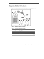
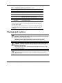
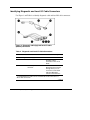
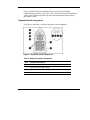
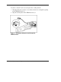
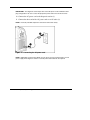
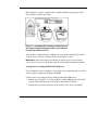
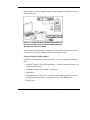
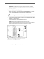
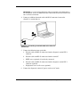
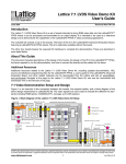
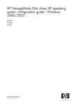
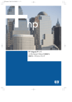
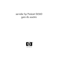
HP ProLiant BL p-Class System Diagnostic Station User Guide Part Number 230859-004 April 2004 (Fourth Edition) © Copyright 2002, 2004 Hewlett-Packard Development Company, L.P. Microsoft and Windows are U.S. registered trademarks of Microsoft Corporation. Intel and Pentium are trademarks or registered trademarks of Intel Corporation or its subsidiaries in the United States and other countries. Java is a US registered trademark of Sun Microsystems, Inc. Hewlett-Packard Company shall not be liable for technical or editorial errors or omissions contained herein. The information in this document is provided “as is” without warranty of any kind and is subject to change without notice. The warranties for HP products are set forth in the express limited warranty statements accompanying such products. Nothing herein should be construed as constituting an additional warranty. April 2004 (Fourth Edition) Part Number 230859-004 Contents Abstract.......................................................................................................... 5 Diagnostic Station Kit Contents................................................................... 6 Warnings and Cautions ................................................................................ 7 Using the Diagnostic Cable or the Local I/O Cable for Configuration or Diagnostic Procedures ................................................................................. 8 Identifying Diagnostic and Local I/O Cable Connectors ................................................... 9 Installing the Diagnostic Cable or the Local I/O Cable.................................................... 11 Diagnostic Station....................................................................................... 11 Overview .......................................................................................................................... 11 Diagnostic Station Components..................................................................................12 Accessing the Cable Storage Area ..............................................................................13 Client PC Requirements..............................................................................................14 Server Blade ..................................................................................................................... 14 Preparing the Server Blade for Connection ................................................................15 Cabling the Diagnostic Station to a Server Blade.......................................................15 Powering Up the Server Blade....................................................................................29 iLO Guidelines for Accessing the Server Blade .........................................................30 GbE Interconnect Switch............................................................................ 32 Regulatory Compliance Notices ................................................................ 32 Regulatory Compliance Identification Numbers.............................................................. 32 Federal Communications Commission Notice ................................................................. 32 Modifications.................................................................................................................... 33 Cables ............................................................................................................................... 33 Canadian Notice ............................................................................................................... 33 Avis Canadien .................................................................................................................. 33 European Union Notice .................................................................................................... 33 Japanese Notice ................................................................................................................ 34 Korean Notice................................................................................................................... 34 HP ProLiant BL p-Class System Diagnostic Station User Guide 3 BSMI Notice ..................................................................................................................... 34 4 HP ProLiant BL p-Class System Diagnostic Station User Guide Abstract This document provides instructions for cabling the diagnostic station to an HP ProLiant BL p-Class server blade to enable out-of-rack communication with the server blade. HP ProLiant BL p-Class System Diagnostic Station User Guide 5 Diagnostic Station Kit Contents NOTE: You may need additional items, depending on the server blade you are using. Figure 1: Diagnostic station kit contents Table 1: Diagnostic Station Kit Contents Item Description 1 Diagnostic station 2 VHDM converter 3 Data transfer cable continued 6 HP ProLiant BL p-Class System Diagnostic Station User Guide Table 1: Diagnostic Station Kit Contents continued Item Description 4 DC power cord (for server blade)1 5 DC power cord (for interconnect switch) 6 AC power cord 2 7 Network cable with RJ-45 connectors Not shown Documentation CD-ROM Not shown This installation guide 1 For information about connecting the diagnostic station to an interconnect switch using this DC power cord, refer to the documentation that ships with the interconnect switch. 2 The AC power cords included with this kit each have a different outlet plug configuration. Be sure to select the proper cord for the electrical service in your facility. Warnings and Cautions WARNING: To reduce the risk of shock or injury from high-current electrical energy, do not remove the server blade access panel while the server blade is connected to the diagnostic station. Powering the server blade with the access cover removed is a service operation and must only be performed by trained service personnel. WARNING: To reduce the risk of shock or injury from high-current electrical energy, do not disable the power cord grounding pin. The grounding pin is an important safety feature. Plug the power cord into a grounded (earthed) electrical outlet that is easily accessible at all times. CAUTION: Remove all power from the diagnostic station before connecting to the server blade. Disconnect all power cords to completely remove power from the diagnostic station. HP ProLiant BL p-Class System Diagnostic Station User Guide 7 CAUTION: Properly ground yourself before beginning any installation procedure. Electrostatic discharge can damage electronic components. For more information about electrostatic discharge, refer to the setup and installation guide. CAUTION: Disconnect the local I/O cable when not in use. The port and connector do not provide a permanent connection. Rear iLO connector performance degrades when the local I/O cable is in use, even when the iLO connector on the cable is not in use. Using the Diagnostic Cable or the Local I/O Cable for Configuration or Diagnostic Procedures Use either the diagnostic cable or the local I/O cable to perform some server blade configuration and diagnostic procedures. Depending on the model, the server blade will have either a diagnostic port or an I/O port. The I/O port only accepts the local I/O cable and the diagnostic port only accepts the diagnostic cable. If the server blade has an I/O icon next to the port on the front of the server blade, use the local I/O cable. If the port has no icon, use the diagnostic cable. Refer to Figure 2 to identify the I/O icon. Figure 2: Local I/O cable with large view of the I/O icon 8 HP ProLiant BL p-Class System Diagnostic Station User Guide Identifying Diagnostic and Local I/O Cable Connectors Use Figure 3 and Table 2 to identify diagnostic cable and local I/O cable connectors. Figure 3: Diagnostic cable (top) and local I/O cable (bottom) connectors Table 2: Diagnostic and Local I/O Cable Connectors Item Connector Name Connector Description Diagnostic cable (top) 1 Server blade connector Provides a direct connection to the server blade. 2 iLO 10/100 Ethernet RJ-45 connector 1 Provides a 10/100 Ethernet RJ-45 connector through which you can access the server blade with the iLO Remote Console and a client PC. 1 A standard Ethernet cable can be used with the RJ-45 connector for a direct cable connection. continued HP ProLiant BL p-Class System Diagnostic Station User Guide 9 Table 2: Diagnostic and Local I/O Cable Connectors continued Item 3 Connector Name Connector Description Kernel debug connector 2 Requires a null modem serial cable and enables trained personnel to perform advanced diagnostic procedures. Local I/O cable (bottom) 3 4 Video connector Provides video capability. 5 USB connector 1 Provides USB connection enabling direct connection to the server blade. 6 USB connector 2 Provides USB connection enabling direct connection to the server blade. 7 Serial connector Requires a null modem serial cable and enables trained personnel to perform advanced diagnostic procedures. 8 iLO 10/100 Ethernet RJ-45 connector 1 Provides a 10/100 Ethernet RJ-45 connector through which you can access the server blade with the iLO Remote Console and a client PC. 9 Server blade connector Provides a direct connection to the server blade. 1 A standard Ethernet cable can be used with the RJ-45 connector for a direct cable connection. 2 The kernel debug connector does not function as a serial port. 3 The local I/O cable is labeled with the I/O icon. The diagnostic cable has no label. 10 HP ProLiant BL p-Class System Diagnostic Station User Guide Installing the Diagnostic Cable or the Local I/O Cable To install the diagnostic cable or the local I/O cable with the diagnostic station, see the “Diagnostic Station” section. To install the diagnostic cable on a server blade in the rack, refer to the setup and installation guide included with the server blade. Diagnostic Station The diagnostic station enables you to power up and communicate with a server blade or an interconnect switch outside of the rack environment. Overview The diagnostic station enables you to perform the following tasks outside of the rack: NOTE: An additional power supply may be required for some ProLiant p-Class products. • Power up a server blade or interconnect switch. • Observe external LEDs. • Test NIC activity. • Configure a server blade or interconnect switch. • Load software on a server blade or interconnect switch. • Test a server blade or interconnect switch after installing an option or upgrade. • Diagnose a server blade or interconnect switch problem using iLO or connecting directly to the server blade. IMPORTANT: The diagnostic station is not designed to function as a continuous power supply replacement. IMPORTANT: The ProLiant BL30p blade sleeve is required when powering a ProLiant BL30p server blade outside of the rack. Only one ProLiant BL30p server blade may be installed in the blade sleeve when receiving power from the diagnostic station. HP ProLiant BL p-Class System Diagnostic Station User Guide 11 For more information about installing hardware options and performing troubleshooting procedures, refer to the p-Class server blade setup and installation guides on the Documentation CD and to the documentation that ships with the interconnect switch. Diagnostic Station Components Use Figure 4 and Table 3 to identify diagnostic station components. Figure 4: Diagnostic station components Table 3: Diagnostic Station Components Item Component Description 1 RJ-45 connector for NIC 1 (PXE default and data) 2 RJ-45 connector for NIC 2 (Data)* 3 RJ-45 connector for NIC 3 (Data)* 4 RJ-45 connector for NIC 4 (iLO) continued 12 HP ProLiant BL p-Class System Diagnostic Station User Guide Table 3: Diagnostic Station Components continued Item Component Description 5 Reserved for additional AC power 6 AC power input connector 7 DC power output connectors 8 Data transfer port 9 NIC LEDs 10 Power On/Off button 11 Power and health LED * This component does not apply to the ProLiant BL30p server blade. Accessing the Cable Storage Area To access the cable storage area: 1. Turn the locking latch clockwise (1). 2. Pull down the cable storage area access door (2). Figure 5: Accessing the cable storage area HP ProLiant BL p-Class System Diagnostic Station User Guide 13 Client PC Requirements Observe the following minimum software and hardware requirements for a client PC: • Intel® Pentium® III or higher processor (700 MHz or greater recommended) • 128 MB of RAM • Microsoft® Windows® 2000 Professional or Microsoft Windows XP operating system • Microsoft Internet Explorer 5.5 or above with 128-bit encryption • Ethernet NIC with 10/100 RJ-45 connector • TCP/IP networking and an IP address compatible with one of the following: — iLO diagnostic port static IP address: 192.168.1.1, mask 255.255.255.0 — Assigned DHCP or static IP address • Any of the following Java Runtime Environment versions: — 1.3.1_02 — 1.3.1_07 — 1.3.1_08 — 1.4.1 for Windows users only — 1.4.2 for Linux users only Access the Java Runtime Environment versions at http://java.sun.com/products/archive/index.html Server Blade Use the following information to connect the diagnostic station to a server blade. 14 HP ProLiant BL p-Class System Diagnostic Station User Guide Preparing the Server Blade for Connection Before connecting the diagnostic station to a server blade: 1. Power down the server blade. 2. Remove the server blade from the server blade enclosure in the rack. IMPORTANT: If the server blade is a ProLiant BL30p, install the server blade into a blade sleeve and connect the blade sleeve to a diagnostic station. 3. Place the server blade on a flat, level workspace. 4. Perform any upgrade or maintenance actions and replace the access panel. Cabling the Diagnostic Station to a Server Blade This document provides two methods for connecting the diagnostic station to a server blade: • Direct cabling methodUse either method to be sure an option is correctly installed in the server blade. This method is recommended for installing an operating system on a server blade. The connection can be made in one of two ways: — With a client PC—Connect to iLO using either the diagnostic port or the I/O port on the front of the server blade. This is a direct, one-to-one connection using the diagnostic cable or the local I/O cable from the client PC to iLO without any hub/switch networking hardware. The iLO diagnostic port static IP address can be found on the diagnostic cable or the local I/O cable, but may be changed under Network Settings in iLO. Depending on the server blade, additional troubleshooting may be performed. CAUTION: Disconnect the local I/O cable when not in use. The port and connector do not provide a permanent connection. Rear iLO connector performance degrades when the local I/O cable is in use, even when the iLO connector on the cable is not in use. HP ProLiant BL p-Class System Diagnostic Station User Guide 15 — With USB devices—Connect the local I/O cable to the I/O port on the front of the server blade. This connection enables you to connect a monitor through the video connector and various USB devices, such as a USB keyboard, USB mouse, USB floppy, and/or a USB CD-ROM, directly to the server. NOTE: Use of the USB hub is optional as the hub is only required when connecting three or more USB devices. For example, you may connect a monitor to the video connector and a USB mouse and USB keyboard to the USB connector. • Network cabling methodUse this method to mimic a network environment and to perform server blade configuration or advanced troubleshooting. In this method, the client PC is connected to the iLO using a hub/switch and the network connections of the diagnostic station. The iLO default configuration enables the server blade to obtain its IP address from a DHCP server. Using the Direct Cabling Method with a Client PC NOTE: Items in addition to those provided with the diagnostic station may be required. Additional items will be noted in the option kits they ship with. NOTE: The server blade in the illustrations may look different from the model you are using. WARNING: To avoid electric shock, be sure that the AC power is disconnected from the diagnostic station when connecting cables to the server blade. 16 HP ProLiant BL p-Class System Diagnostic Station User Guide To connect a client PC to the server using the direct cabling method: 1. Thread the DC power cord for a server blade or blade sleeve through the opening in the VHDM converter (1). 2. Snap the cord into place in the VHDM converter (2). Figure 6: Threading the DC power cord through the VHDM converter HP ProLiant BL p-Class System Diagnostic Station User Guide 17 3. Place the VHDM converter on the rear of the server blade or the blade sleeve by inserting the tab into the right side (1), making sure the pins on the left side are properly aligned. 4. Tighten the thumbscrew to secure the VHDM converter to the server blade (2) or the blade sleeve. 5. Insert the DC power cord into one of the diagnostic station DC power connectors (3). Figure 7: Attaching the VHDM converter and connecting the DC power cord 18 HP ProLiant BL p-Class System Diagnostic Station User Guide 6. Connect the data transfer cable to the VHDM converter on the server blade (1) or the blade sleeve. 7. Connect the other end of the data transfer cable to the diagnostic station (2). Figure 8: Connecting the data transfer cable HP ProLiant BL p-Class System Diagnostic Station User Guide 19 8. Connect the server blade to the client PC using the diagnostic cable. If you are using the local I/O cable to connect to the I/O port, go to step 9. CAUTION: Disconnect the diagnostic cable when not in use. The port and connector do not provide a permanent connection. Rear iLO connector performance degrades when the local I/O cable is in use, even when the iLO connector on the cable is not in use. a. Connect the network cable with RJ-45 connectors to the client PC (1). b. Connect the other end of the RJ-45 network cable to the diagnostic cable (2). The kernel debug connector can remain unused. c. Connect the diagnostic cable to the diagnostic port on the front of the server blade (3). d. Go to step 10. Figure 9: Connecting the server blade to a client PC using the diagnostic cable 20 HP ProLiant BL p-Class System Diagnostic Station User Guide 9. Connect the server blade to a client PC using the local I/O cable. CAUTION: Disconnect the local I/O cable when not in use. The port and connector do not provide a permanent connection. Rear iLO connector performance degrades when the local I/O cable is in use, even when the iLO connector on the cable is not in use. a. Connect the network cable with RJ-45 connectors to the client PC (1). b. Connect the other end of the RJ-45 network cable to the local I/O cable (2). The remaining connectors can remain unused. c. Connect the local I/O cable to the I/O port on the front of the server blade (3). Figure 10: Connecting the server blade to a client PC using the local I/O cable HP ProLiant BL p-Class System Diagnostic Station User Guide 21 IMPORTANT: If you are connecting to a ProLiant BL30p server blade, the server blade must be installed in the left slot of the blade sleeve on a flat surface. Figure 11: Connecting the ProLiant BL30p server blade to a client PC using the local I/O cable 22 HP ProLiant BL p-Class System Diagnostic Station User Guide IMPORTANT: The diagnostic station ships with several AC power cords of different outlet plug configurations. Be sure to select the proper AC power cord for the electrical service. 10. Connect the AC power cord to the diagnostic station (1). 11. Connect the other end of the AC power cord to an AC outlet (2). NOTE: Previously installed components have been removed for clarity. Figure 12: Connecting the AC power cord NOTE: Depending on which server blade you are using, you may need to install a second power supply in the diagnostic station. A second power cord would also be required. HP ProLiant BL p-Class System Diagnostic Station User Guide 23 Refer to Figure 13 for the completed direct cabling method using diagnostic cable (left) and the local I/O cable (right). Figure 13: Completed direct cabling method (front and rear views) using the diagnostic cable (1) and the local I/O cable (2) to connect to iLO After the direct cabling method is complete, the server blade and diagnostic station are ready for use. See the “Powering Up the Server Blade” section. IMPORTANT: Before removing the local I/O cable, completely log out of the current iLO session. Do not remove the local I/O cable when the Unit Identification (UID) LED is blinking. Using the Direct Cabling Method with USB Devices Use the following setup to configure a server blade using a SmartStart CD or to load software updates and patches using the CD-ROM. Connect to the server using the direct cabling method with USB devices: 1. Follow steps 1 through 7 of “Using the Direct Cabling Method with a Client PC” to make connections from the server blade to the Diagnostic Station. 2. Connect the server blade connector on the local I/O cable to the server blade. 24 HP ProLiant BL p-Class System Diagnostic Station User Guide CAUTION: Disconnect the local I/O cable when not in use. The port and connector do not provide a permanent connection. Rear iLO connector performance degrades when the local I/O cable is in use, even when the iLO connector on the cable is not in use. 3. Connect the monitor to the video connector on the local I/O cable. 4. Connect a USB hub to the USB connector on the local I/O cable. NOTE: Use of the USB hub is optional as you may connect to the server using any combination of USB devices. For example, you may connect a monitor to the video connector and a USB mouse and USB keyboard to the USB connector. 5. Connect the following to the USB hub: a. USB CD-ROM and/or USB floppy b. USB keyboard c. USB mouse HP ProLiant BL p-Class System Diagnostic Station User Guide 25 Refer to Figure 14 for the completed direct cabling method using USB devices and the local I/O cable. Figure 14: Completed direct cabling method (front and rear view) using the local I/O cable and USB devices to directly access the server blade After the direct cabling method is complete, the server blade and diagnostic station are ready for use. See the “Powering Up the Server Blade” section. Using the Network Cabling Method In addition to the diagnostic station and contents, you need to supply the following items: 26 • Client PC (See the “Client PC Requirements” section for minimum software and hardware requirements.) • Additional network cable with RJ-45 connectors • Hub/switch • Deployment server or file server (optional) for operating system deployment or file management (may be the same physical server as the DHCP server) • DHCP server HP ProLiant BL p-Class System Diagnostic Station User Guide IMPORTANT: The DHCP server assigns the IP address to the iLO NIC. The DHCP server is not necessary if you have configured iLO and/or any other connected NICs to use a static IP address. To connect with the network cabling method: 1. Follow steps 1 through 7 of “Using the Direct Cabling Method with a Client PC” to make the connections from the server blade to the diagnostic station. WARNING: To avoid electric shock, be sure that the AC power is disconnected from the diagnostic station when connecting cables to the server blade. 2. Connect the network cable with RJ-45 connectors to the diagnostic station NIC 4 connector (1) and to the hub (2). 3. Connect the AC power cord to the diagnostic station (3). NOTE: Previously installed components have been removed for clarity. Depending on which server blade you are using, you may need to install a second power supply in the diagnostic station. A second power cord would also be required. Figure 15: Connecting a network cable and the AC power cord to the diagnostic station HP ProLiant BL p-Class System Diagnostic Station User Guide 27 IMPORTANT: If you are using the diagnostic station for operating system deployment or file management, connect an additional network cable with RJ-45 connectors between the NIC 1 connector and the hub. 4. Connect an additional network cable with RJ-45 connectors between the client PC (1) and the hub (2). Figure 16: Connecting a network cable to the client PC and the hub 5. Connect the following items to the hub: a. Network cable with RJ-45 connectors from the diagnostic station NIC 4 connector b. Network cable with RJ-45 connectors from the client PC c. DHCP server (optional), if not already connected d. Network cable with RJ-45 connectors from the diagnostic station NIC 1 connector (optional) e. Deployment server or file server (optional) 6. Connect the diagnostic station AC power cord to an AC outlet. 28 HP ProLiant BL p-Class System Diagnostic Station User Guide Figure 17 shows a completed network cabling method with the DHCP server (1) and the hub (2). IMPORTANT: For operating system deployment or file management, an optional server can be connected to the hub. NOTE: Connecting the diagnostic cable to the diagnostic port or connecting the local I/O cable to the I/O port automatically disables the iLO connection on the rear of the diagnostic station. Figure 17: Completed network cabling method NOTE: Your completed configuration may look different, depending on which server blade you are using. After the network cabling method is complete, the server blade and diagnostic station are ready for use. See the “Powering Up the Server Blade” section. Powering Up the Server Blade To power up the server blade: 1. Power up the diagnostic station by pressing the Power On/Off button. 2. Power up the server blade. HP ProLiant BL p-Class System Diagnostic Station User Guide 29 3. Power up the client PC in accordance with its own documentation. NOTE: iLO may take up to 90 seconds to establish a secure network connection. IMPORTANT: If tasks are to be performed on more than one ProLiant BL30p server blade, power down the first server blade and remove it from the blade sleeve. Then, install the next server blade in the left bay of the blade sleeve when the blade sleeve is laying on a flat surface. iLO Guidelines for Accessing the Server Blade Use the following guidelines when you prepare to access the server blade with the iLO Remote Console for the first time. Two cabling methods are available to make the wiring connections from the client PC to the iLO: the direct cabling method and the network cabling method. NOTE: Refer to the setup and installation guide for the server blade you are using for information on accessing the server blade with the iLO Remote Console. NOTE: If using the RJ-45 connector on the Diagnostic Station to connect to iLO, the iLO connector from the iLO interconnects is disabled. IMPORTANT: Before removing the local I/O cable, completely log out of the current iLO session. Do not remove the local I/O cable when the UID LED is blinking. Direct Cabling Method In this method, the client PC is connected to the iLO using the diagnostic port or the I/O port on the front of the server blade. This is a direct, one-to-one connection using the diagnostic cable or the local I/O cable from the client PC to iLO without any hub/switch networking hardware. The iLO diagnostic port static IP address can be found on the diagnostic cable and the I/O port static IP address can be found on the local I/O cable. 30 HP ProLiant BL p-Class System Diagnostic Station User Guide Network Cabling Method In this method, the client PC is connected to the iLO using a hub/switch and the network connections of the diagnostic station. The iLO default configuration enables the server blade to obtain its IP address from a DHCP server. NOTE: If you have edited the configuration to use a static IP address, iLO uses this same static IP address when you connect with the network cabling method. Connection Information and Browser Compatibility To access iLO, you need some basic connection information: • The TCP/IP address or DNS/WINS name of the iLO — When using the direct cabling method, use the 192.168.1.1 for the TCP/IP address and 255.255.255.0 for the subnet mask. — When using the network cabling method, look on the iLO Default Network Settings tag for first time access. • A valid user ID and password with appropriate iLO privileges for accessing Remote Console This information is also available on the iLO Default Network Settings tag for initial access information. Be sure that the IP address and subnet mask of the client PC are compatible with the IP address and subnet mask of the iLO diagnostic port. In addition, be sure that the browser bypasses any proxy servers for the IP address or DNS/WINS name of the iLO. HP ProLiant BL p-Class System Diagnostic Station User Guide 31 GbE Interconnect Switch You can configure or troubleshoot a GbE interconnect switch in an out-of-rack environment. In this situation, the diagnostic station provides power to the interconnect switch. Use the following items from the diagnostic station kit: • Diagnostic station • DC power cord (for interconnect switch) • Network cable with RJ-45 connectors • AC power cord For setup and operating instructions, refer to the documentation that ships with the interconnect switch. Regulatory Compliance Notices Regulatory Compliance Identification Numbers For the purpose of regulatory compliance certifications and identification, your product has been assigned a unique HP series number. The series number can be found on the product nameplate label, along with all required approval markings and information. When requesting compliance information for this product, always refer to this series number. The series number should not be confused with the marketing name or model number of the product. Federal Communications Commission Notice This equipment has been tested and found to comply with the limits for a Class A digital device, pursuant to Part 15 of the FCC Rules. These limits are designed to provide reasonable protection against harmful interference when the equipment is operated in a commercial environment. This equipment generates, uses, and can radiate radio frequency energy and, if not installed and used in accordance with the instructions, may cause harmful interference to radio communications. Operation of this equipment in a residential area is likely to cause harmful interference, in which case the user will be required to correct the interference at personal expense. 32 HP ProLiant BL p-Class System Diagnostic Station User Guide Modifications The FCC requires the user to be notified that any changes or modifications made to this device that are not expressly approved by Hewlett-Packard Company may void the user's authority to operate the equipment. Cables Connections to this device must be made with shielded cables with metallic RFI/EMI connector hoods in order to maintain compliance with FCC Rules and Regulations. Canadian Notice This Class A digital apparatus meets all requirements of the Canadian InterferenceCausing Equipment Regulations. Avis Canadien Cet appareil numérique de la classe A respecte toutes les exigences du Règlement sur le matériel brouilleur du Canada. European Union Notice Products bearing the CE marking comply with the EMC Directive (89/336/EEC) and the Low Voltage Directive (73/23/EEC) issued by the Commission of the European Community and if this product has telecommunication functionality, the R&TTE Directive (1999/5/EC). Compliance with these directives implies conformity to the following European Norms (in parentheses are the equivalent international standards and regulations): • EN 55022 (CISPR 22) – Electromagnetic Interference • EN55024 (IEC61000-4-2, 3, 4, 5, 6, 8, 11) – Electromagnetic Immunity • EN61000-3-2 (IEC61000-3-2) – Power Line Harmonics HP ProLiant BL p-Class System Diagnostic Station User Guide 33 • EN61000-3-3 (IEC61000-3-3) – Power Line Flicker • EN 60950 (IEC 60950) – Product Safety Japanese Notice Korean Notice BSMI Notice 34 HP ProLiant BL p-Class System Diagnostic Station User Guide