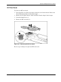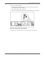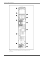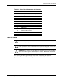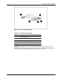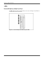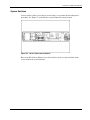
1
HP ProLiant BL30p Server Blade Maintenance and Service Guide May 2004 (First Edition) Part Number 354537-001 © Copyright 2004 Hewlett-Packard Development Company, L.P. The information contained herein is subject to change without notice. The only warranties for HP products and services are set forth in the express warranty statements accompanying such products and services. Nothing herein should be construed as constituting an additional warranty. HP shall not be liable for technical or editorial errors or omissions contained herein. Microsoft and Windows are U.S. registered trademarks of Microsoft Corporation. Intel and Xeon are trademarks or registered trademarks of Intel Corporation or its subsidiaries in the United States and other countries. HP ProLiant BL30p Server Blade Maintenance and Service Guide May 2004 (First Edition) Part Number 354537-001 Contents About This Guide Audience Assumptions..................................................................................................................................v Technician Notes...........................................................................................................................................v Where to Go for Additional Help.................................................................................................................vi Integrated Management Log ..................................................................................................................vi Telephone Numbers ............................................................................................................................. vii Chapter 1 Illustrated Parts Catalog ProLiant BL30p Server Blade Components .............................................................................................. 1-2 System Exploded View....................................................................................................................... 1-2 BL30p Server Blade Sleeve and Blanks Exploded View ................................................................... 1-3 Server Blade Spare Parts List ............................................................................................................. 1-4 Chapter 2 Removal and Replacement Procedures Safety Considerations................................................................................................................................ 2-1 Electrostatic Discharge Information ................................................................................................... 2-1 Server Blade Warnings and Cautions ................................................................................................. 2-1 Rack Warnings and Cautions.............................................................................................................. 2-2 Symbols on Equipment ....................................................................................................................... 2-3 Server Blade Components ......................................................................................................................... 2-3 Server Blade Preparation .................................................................................................................... 2-4 Hard Drives......................................................................................................................................... 2-6 DIMMs.............................................................................................................................................. 2-11 Processors and Heatsinks.................................................................................................................. 2-12 Fan Assembly ................................................................................................................................... 2-17 Dual Port Fibre Channel Adapter ..................................................................................................... 2-18 NIC Riser Board ............................................................................................................................... 2-19 Power Converter Module.................................................................................................................. 2-20 Power Button/LED Cable ................................................................................................................. 2-21 Server Blade Handle ......................................................................................................................... 2-22 System Board Assembly ................................................................................................................... 2-23 Battery............................................................................................................................................... 2-24 ProLiant BL30p Blade Sleeve ................................................................................................................. 2-26 Removing the Blade Sleeve .............................................................................................................. 2-26 Removing the Blade Sleeve Board ................................................................................................... 2-27 Server Blade Blanks.......................................................................................................................... 2-28 HP ProLiant BL30p Server Blade Maintenance and Service Guide iii Contents Chapter 3 Diagnostic Tools ProLiant BL p-Class Diagnostic Tools ......................................................................................................3-1 Firmware Upgrades for Management Modules .........................................................................................3-3 Chapter 4 Connectors, LEDs, and Switches Connectors .................................................................................................................................................4-1 ProLiant BL30p Server Blade .............................................................................................................4-1 Local I/O Cable ...................................................................................................................................4-5 LEDs ..........................................................................................................................................................4-8 ProLiant BL30p Server Blade Front Panel..........................................................................................4-8 Switches and Buttons...............................................................................................................................4-10 Power On/Standby Button.................................................................................................................4-10 System Switches................................................................................................................................4-11 Chapter 5 Server Blade Specifications ProLiant BL30p Server Blade .............................................................................................................5-1 ATA Hard Drive..................................................................................................................................5-2 Index iv HP ProLiant BL30p Server Blade Maintenance and Service Guide About This Guide This maintenance and service guide can be used for reference when servicing HP ProLiant BL30p server blades. WARNING: To reduce the risk of personal injury from electric shock and hazardous energy levels, only authorized service technicians should attempt to repair this equipment. Improper repairs can create conditions that are hazardous. Audience Assumptions This guide is for service technicians. HP assumes you are qualified in the servicing of computer equipment and trained in recognizing hazard in products with hazardous energy levels and are familiar with weight and stability precautions for rack installations. Technician Notes WARNING: Only authorized technicians trained by HP should attempt to repair this equipment. All troubleshooting and repair procedures are detailed to allow only subassembly/module-level repair. Because of the complexity of the individual boards and subassemblies, no one should attempt to make repairs at the component level or to make modifications to any printed wiring board. Improper repairs can create a safety hazard. WARNING: To reduce the risk of personal injury from electric shock and hazardous energy levels, do not exceed the level of repairs specified in these procedures. Because of the complexity of the individual boards and subassemblies, do not attempt to make repairs at the component level or to make modifications to any printed wiring board. Improper repairs can create conditions that are hazardous. WARNING: To reduce the risk of electric shock or damage to the equipment: • Disconnect power from the system by unplugging all power cords from the power supplies. • Do not disable the power cord grounding plug. The grounding plug is an important safety feature. • Plug the power cord into a grounded (earthed) electrical outlet that is easily accessible at all times. HP ProLiant BL30p Server Blade Maintenance and Service Guide v About This Guide CAUTION: To properly ventilate the system, you must provide at least 7.6 cm (3.0 in.) of clearance at the front and back of the server. CAUTION: The computer is designed to be electrically grounded (earthed). To ensure proper operation, plug the AC power cord into a properly grounded AC outlet only. NOTE: Any indications of component replacement or printed wiring board modifications may void any warranty. Where to Go for Additional Help In addition to this guide, the following information sources are available on the documentation CD provided with the server blade enclosure, or on www.hp.com: • HP ProLiant BL System Best Practices Guide • HP ProLiant BL System Common Practices Guide • HP ProLiant BL p-Class System Setup and Installation Guide • HP ProLiant BL p-Class System Hardware Installation and Configuration Instructions • HP ProLiant Servers Troubleshooting Guide • Altiris eXpress Deployment Server for HP ProLiant Servers User Guide • HP Integrated Lights-Out User Guide • ROM-Based Setup Utility User Guide • White Paper: HP ProLiant BL p-Class System Overview and Planning • White Paper: Configuring a Preboot eXecution Environment (PXE) using Red Hat Linux 7.2 on HP ProLiant Servers • QuickSpecs • Service Quick Reference Guide Integrated Management Log The server includes an integrated, nonvolatile management log that contains fault and management information. The contents of the Integrated Management Log (IML) can be viewed with HP Systems Insight Manager (HP SIM). vi HP ProLiant BL30p Server Blade Maintenance and Service Guide About This Guide Telephone Numbers For the name of the nearest HP authorized reseller: • In the United States, call 1-800-345-1518. • In Canada, call 1-800-263-5868. For HP technical support: • In the United States and Canada, call 1-800-633-3300. • Outside the United States and Canada, refer to www.hp.com HP ProLiant BL30p Server Blade Maintenance and Service Guide vii 1 Illustrated Parts Catalog This chapter provides illustrated parts and spare parts lists for the HP ProLiant BL30p server blade components. Refer to Table 1-1 for the names of referenced spare parts. HP ProLiant BL30p Server Blade Maintenance and Service Guide 1-1 Illustrated Parts Catalog ProLiant BL30p Server Blade Components System Exploded View Figure 1-1: System exploded view 1-2 HP ProLiant BL30p Server Blade Maintenance and Service Guide Illustrated Parts Catalog BL30p Server Blade Sleeve and Blanks Exploded View Figure 1-2: Sleeve and blanks exploded view HP ProLiant BL30p Server Blade Maintenance and Service Guide 1-3 Illustrated Parts Catalog Server Blade Spare Parts List Table 1-1: Server Blade Spare Parts List Item Description Spare Part Number Mechanical Components 1 System board assembly 1a Heatsinks (2) * 1b Server blade handle screw and spring* 361743-001 System Components 2 Processors 2a Intel XeonTM 3.06-GHz processor with 512-KB cache (includes one heatsink) 333055-001 2b Intel Xeon 3.2-GHz processor with 1-MB cache (includes one heatsink) * 348272-001 2c Intel Xeon 3.2-GHz processor with 2-MB cache (includes one heatsink) * 360316-001 (Reserved) 3 Fan assembly 361748-001 4 NIC riser board 361745-001 5 Power converter module 361752-001 Miscellaneous 6 Hardware kit * 6a Server blade blank 6b Drive cage assembly 6c Processor blank 7 361750-001 Cable kit * 7a LED cable * 7b Hard drive cable * 361749-001 8 Replacement battery, 3-V lithium * 234556-001 9 Local I/O cable * 355935-001 10 Heatsink 361747-001 Memory DIMMs 11a DIMM, 512-MB, ECC registered PC2100 DDR SDRAM * 300700-001 11b DIMM, 1-GB, ECC registered PC2100 DDR SDRAM * 300701-001 11c DIMM, 2-GB, ECC registered PC2100 DDR SDRAM * 300702-001 * Not shown continued 1-4 HP ProLiant BL30p Server Blade Maintenance and Service Guide Illustrated Parts Catalog Table 1-1: Server Blade Spare Parts List continued Item Description Spare Part Number Options 12 Dual Port Fibre Channel Adapter 361744-001 13 Hard drive, 60-GB 361751-001 14 RJ-45 Patch Panel 2, with Fibre Channel support * 322299-001 15 Transceiver, 2-GB, Fibre Channel * 229204-001 16 GbE2 Interconnect Switch * 321148-001 17 ProLiant BL30p blade sleeve cover 361881-001 18 ProLiant BL30p blade sleeve board 361746-001 * Not shown HP ProLiant BL30p Server Blade Maintenance and Service Guide 1-5 2 Removal and Replacement Procedures This chapter provides subassembly/module-level removal and replacement procedures for system components. After completing all necessary removal and replacement procedures, verify that all components operate properly by running the appropriate diagnostic software: • For server blade components, run the Server Diagnostics Utility, available from the HP website: www.hp.com • For server blade enclosure and power enclosure components, run the infrastructure diagnostics. Refer to Chapter 3, “Dia gnostic Tools,” for more information. Safety Considerations Electrostatic Discharge Information A discharge of static electricity can damage static-sensitive devices or microcircuitry. Proper packaging and grounding techniques are necessary precautions to prevent damage. To prevent electrostatic damage, observe the following precautions: • Transport products in static-safe containers such as conductive tubes, bags, or boxes. • Keep electrostatic-sensitive parts in their containers until they arrive at static-free stations. • Cover workstations with approved static-dissipating material. Use a wrist strap connected to the work surface and properly grounded tools and equipment. • Keep the work area free of nonconductive materials such as ordinary plastic assembly aids and foam packing. • Always be properly grounded when touching a static-sensitive component or assembly. • Use conductive field service tools. Server Blade Warnings and Cautions WARNING: Setting the server blade Power On/Standby button to the standby position removes power from most areas of the server blade. This process may take 30 seconds, during which time some internal circuitry remains active. To remove power completely, remove the server blade from the server blade enclosure. HP ProLiant BL30p Server Blade Maintenance and Service Guide 2-1 Removal and Replacement Procedures WARNING: To reduce the risk of personal injury from hot surfaces, allow the internal system components to cool before touching them. CAUTION: When performing non-hot-plug operations, you must power down the server blade and/or the system. However, it may be necessary to leave the server blade powered up when performing other operations, such as hot-plug installations or troubleshooting. Rack Warnings and Cautions WARNING: The power supply enclosure and the server blade enclosure are very heavy. To reduce the risk of personal injury or damage to the equipment: • Observe local occupational health and safety requirements and guidelines for manual material handling. • Remove hot-plug power supplies and server blades from their enclosures before installing or removing the enclosures. • Use caution and get help to lift and stabilize enclosures during installation or removal, especially when the enclosure is not fastened to the rack. WARNING: Always use at least two people to lift a power supply enclosure or server blade enclosure into the rack. If the enclosure is being loaded into the rack above chest level, a third person MUST assist with aligning the enclosure with the rails while the other two people support the weight of the enclosure. WARNING: To reduce the risk of personal injury or damage to the equipment, be sure that: • The leveling jacks of the rack are extended to the floor. • The full weight of the rack rests on the leveling jacks. • The stabilizers are attached to the rack if it is a single rack installation. • The racks are coupled in multiple rack installations. WARNING: When installing the server blade enclosure in a telco rack, be sure that the rack frame is adequately secured to the building structure. WARNING: To reduce the risk of personal injury or damage to the equipment, at least two people are needed to safely unload the rack from the pallet. An empty 42U rack weighs 115 kg (253 lb), is over 2.1 m (7 ft) tall, and may become unstable when being moved on its casters. Do not stand in front of the rack as it rolls down the ramp from the pallet, but handle the rack from both sides. WARNING: To reduce the risk of shock or injury from high-current electrical energy, do not reach into a server blade enclosure once it has been installed in a rack and connected to a working rack bus bar. Do not touch the power or data backplanes within the server blade enclosure once it has been installed. 2-2 HP ProLiant BL30p Server Blade Maintenance and Service Guide Removal and Replacement Procedures WARNING: To reduce the risk of shock or injury from high-current electrical energy, do not reach into a power supply enclosure once it has been installed in a rack and connected to a power source. Do not touch the connectors within the power supply enclosure once it has been installed. WARNING: To reduce the risk of shock or injury from high-current electrical energy, do not open any access covers on the rack bus bar or power bus box after it has been connected to a power source. CAUTION: Always ensure that equipment is properly grounded before beginning any installation procedure. Electrostatic discharge resulting from improper grounding can damage electronic components. For more information, refer to the setup and installation guide. Symbols on Equipment Any product or assembly marked with these symbols indicates that the component exceeds the recommended weight for one individual to handle safely. 25 kg 55 lb WARNING: To reduce the risk of personal injury or damage to the equipment, observe local occupational health and safety requirements and guidelines for manual material handling. Any surface or area of the equipment marked with these symbols indicates the presence of a hot surface or hot component. WARNING: To reduce the risk of injury from a hot component, allow the surface to cool before touching it. To reduce the risk of injury from electric shock hazards, do not open this enclosure. WARNING: Any surface or area of the equipment marked with these symbols indicates the presence of electric shock hazards. The enclosed area contains no operator serviceable parts. Any RJ-45 receptacle marked with these symbols indicates a Network Interface Connection (NIC). WARNING: To reduce the risk of electric shock, fire, or damage to the equipment, do not plug telephone or telecommunications connectors into this receptacle. Server Blade Components Use the procedures in this section to perform service events on ProLiant BL30p server blades. NOTE: Slate blue denotes serviceable parts, and port denotes hot-plug parts. HP ProLiant BL30p Server Blade Maintenance and Service Guide 2-3 Removal and Replacement Procedures Server Blade Preparation To service any internal server blade component, you must power down the server blade and remove it from the server blade enclosure. NOTE: When removing a server blade, it is not necessary to remove the blade sleeve from the enclosure. CAUTION: Electrostatic discharge can damage electronic components. Be sure you are properly grounded before beginning any installation procedure. For more information, refer to the “Electrostatic Discharge Information” section in this chapter. System power in server blades does not completely shut off with the front panel Power On/Standby switch or Integrated Lights-Out (iLO) Virtual Power Button feature. The function toggles between on and standby modes, rather than on and off. The standby position removes power from most electronics and the drives, but portions of the power supply and some internal circuitry remain active. To service internal server blade components: 1. Identify the proper server blade in the server blade enclosure. 2. Remove power from the server blade in one of the following ways: — Use the Virtual Power Button feature in iLO to power down the server blade from a remote location. Be sure that the server blade is in standby mode by observing that the power LED is amber. — Press the Power On/Standby button on the front of the server blade. Be sure that the server blade is in standby mode by observing that the power LED is amber. CAUTION: After you press the release button, the server blade is unlocked from the blade sleeve and can then be removed from the enclosure. Use both hands to support the server blade when you remove it from the rack. 2-4 HP ProLiant BL30p Server Blade Maintenance and Service Guide Removal and Replacement Procedures 3. Remove the server blade from the server blade enclosure: a. Press the release button (1). b. Open the lever (2). c. Grasp the lever and slide the server blade from the enclosure (3). Place a hand under the server blade to support it as you remove it from the enclosure. NOTE: When removing a server blade, it is not necessary to remove the blade sleeve from the enclosure. Figure 2-1: Removing the server blade from the blade sleeve in the server blade enclosure d. Place the server blade on a flat, level surface. CAUTION: Always populate server blade enclosure bays with either a server blade or server blade blank. Operating the enclosure without a server blade or server blade blank results in improper airflow and improper cooling that can lead to thermal damage. Reverse steps 1 through 3 to install and power up a server blade. Server blades are set to power up automatically upon insertion. If you have changed this setting, use the Power On/Standby button or iLO Virtual Power Button feature to power up the server blade. For more information about iLO, refer to the Integrated Lights-Out User Guide. HP ProLiant BL30p Server Blade Maintenance and Service Guide 2-5 Removal and Replacement Procedures Hard Drives To replace a hard drive: 1. Back up the server blade data. 2. Remove the server blade from the server blade enclosure. Refer to “Server Blad e Preparation” in this chapter. Figure 2-2: Removing the drive cage assembly Figure 2-3: Removing the cover plate from the drive cage assembly 2-6 HP ProLiant BL30p Server Blade Maintenance and Service Guide Removal and Replacement Procedures Figure 2-4: Removing a hard drive from the drive cage assembly Figure 2-5: Removing the center plate from the drive cage assembly HP ProLiant BL30p Server Blade Maintenance and Service Guide 2-7 Removal and Replacement Procedures Figure 2-6: Removing a second hard drive IMPORTANT: Be sure the hard drive label is on the top side of the hard drive when installed in the drive cage assembly. Figure 2-7: Replacing a hard drive 2-8 HP ProLiant BL30p Server Blade Maintenance and Service Guide Removal and Replacement Procedures Figure 2-8: Replacing the center plate NOTE: Be sure that the jumper on the drive is set to Cable Select (CS) so that the drive device ID is determined by the cable. IMPORTANT: Be sure the center plate is oriented as in the following figure. The pins must be pointed down when being installed into the main cage. Figure 2-9: Replacing cover plate on the drive cage assembly IMPORTANT: Be sure to connect the hard drive in the primary (bottom) bay to the primary (bottom) connector on the hard drive cable and connect the hard drive in the secondary (top) bay to the secondary (top) connector on the hard drive cable. HP ProLiant BL30p Server Blade Maintenance and Service Guide 2-9 Removal and Replacement Procedures Figure 2-10: Reinstalling the drive cage assembly 2-10 HP ProLiant BL30p Server Blade Maintenance and Service Guide Removal and Replacement Procedures DIMMs To remove a DIMM: 1. Power down the server blade and remove it from the server blade enclosure. Refer to the “Server Blad e Preparation” section in this chapter. NOTE: The server blade ships with one 1-GB DIMM installed in slot 1. 2. Open the DIMM slot latches (1). 3. Remove the DIMM from the slot (2). Figure 2-11: Removing a DIMM IMPORTANT: For proper DIMM configuration, refer to the HP ProLiant BL30p Server Blade Setup and Installation Guide. CAUTION: Use only HP DIMMs. DIMMs from other sources may adversely affect data integrity. IMPORTANT: DIMMs do not seat fully if turned the wrong way. Reverse steps 1 through 3 to replace a DIMM. NOTE: Installing DIMMs in pairs allows interleaving functionality. HP ProLiant BL30p Server Blade Maintenance and Service Guide 2-11 Removal and Replacement Procedures Processors and Heatsinks CAUTION: If installing only one processor in the server blade, be sure to install a processor blank in processor socket 2. A processor blank may need to be removed before installing an additional processor. Figure 2-12: Removing a processor blank 2-12 HP ProLiant BL30p Server Blade Maintenance and Service Guide Removal and Replacement Procedures To remove a processor: 1. Remove the heatsink (3). CAUTION: The heatsink is not reusable and must be discarded if removed from the processor after application. Figure 2-13: Removing the heatsink HP ProLiant BL30p Server Blade Maintenance and Service Guide 2-13 Removal and Replacement Procedures 2. Remove the processor (2). Figure 2-14: Removing the processor To replace the processor: CAUTION: When installing the processor into the socket, be sure that the locking lever is raised to avoid damaging pins. 1. Align the processor and install the processor into the socket (1). 2. Close the processor locking lever (2). Figure 2-15: Replacing the processor 2-14 HP ProLiant BL30p Server Blade Maintenance and Service Guide Removal and Replacement Procedures CAUTION: Be sure that the processor socket locking lever is closed. Do not force the lever closed after the processor installation; it should close without resistance. Forcing the lever closed may result in damage to the processor and its socket, requiring replacement of the system board. 3. Remove the thermal interface media cover from the heatsink. Figure 2-16: Removing the thermal interface media cover CAUTION: After the cover is removed, do not touch the thermal interface media. IMPORTANT: The heatsink is not reusable and must be discarded if removed from the processor after application. HP ProLiant BL30p Server Blade Maintenance and Service Guide 2-15 Removal and Replacement Procedures 4. Align the heatsink and install onto processor (1). 5. Close the heatsink brace (2). 6. Close the heatsink locking lever (3). Figure 2-17: Replacing the heatsink CAUTION: If installing only one processor in the server blade, be sure to install a processor blank in processor socket 2. 2-16 HP ProLiant BL30p Server Blade Maintenance and Service Guide Removal and Replacement Procedures Fan Assembly To remove the fan assembly: 1. Power down the server blade and remove it from the server blade enclosure. Refer to the “Server Blad e Preparation” section in this chapter. 2. Lay the server blade on a flat, stable surface. 3. Disconnect the two fan cables from the system board. Figure 2-18: Disconnecting fan cables 4. Squeeze the retaining clips on the fan assembly (1) and lift the fan assembly from the retaining brackets (2). Figure 2-19: Removing the fan assembly Reverse steps 1 through 4 to replace the fan assembly. HP ProLiant BL30p Server Blade Maintenance and Service Guide 2-17 Removal and Replacement Procedures Dual Port Fibre Channel Adapter To remove the Dual Port Fibre Channel (FC) adapter: 1. Power down the server blade and remove it from the server blade enclosure. Refer to the “Server Blad e Preparation” section in this chapter. 2. Loosen the thumbscrews (1). 3. Remove the FC Adapter (2). Figure 2-20: Removing the Dual Port Fibre Channel adapter Reverse steps 1 through 3 to replace the FC adapter. 2-18 HP ProLiant BL30p Server Blade Maintenance and Service Guide Removal and Replacement Procedures NIC Riser Board To remove the NIC riser board: 1. Power down the server blade and remove it from the server blade enclosure. Refer to the “Server Blad e Preparation” section in this chapter. 2. Remove the FC adapter. Refer to “Dual Port Fibre Channel Adapter” in this chapter. 3. Loosen the thumbscrews (1). 4. Remove the NIC riser board (2). Figure 2-21: Removing the NIC riser board Reverse steps 1 through 4 to replace the NIC riser board. HP ProLiant BL30p Server Blade Maintenance and Service Guide 2-19 Removal and Replacement Procedures Power Converter Module To remove the power converter module: 1. Power down the server blade and remove it from the server blade enclosure. Refer to the “Server Blad e Preparation” section in this chapter. 2. Remove the FC adapter. Refer to “Dual Port Fibre Channel Adapter” in this chapter. 3. Remove the NIC riser board. Refer to “NIC Rise r Board” in this chapter. 4. Release the two clips securing the power converter module to the system board (1). 5. Remove the power converter module (2). Figure 2-22: Removing the Power Converter Module Reverse steps 1 through 5 to replace the power converter module. 2-20 HP ProLiant BL30p Server Blade Maintenance and Service Guide Removal and Replacement Procedures Power Button/LED Cable The power button/LED cable is included in the cable kit. To remove the power button/LED cable: 1. Power down the server blade and remove it from the server blade enclosure. Refer to the “Server Blad e Preparation” section in this chapter. 2. Remove the cable. Figure 2-23: Removing the power button/LED cable Use the same connectors in the illustration to replace the power button/LED cable. HP ProLiant BL30p Server Blade Maintenance and Service Guide 2-21 Removal and Replacement Procedures Server Blade Handle The server blade handle contains a serial number that maintains the original server blade warranty. In the event that the system board assembly is replaced, the original handle must be removed, and attached to the new server blade system board assembly. To remove the server blade handle: 1. Power down the server blade and remove it from the server blade enclosure. Refer to “Server Blad e Preparation” in this chapter. 2. Remove the screw attaching the handle to the server blade. 3. Remove the handle. Be sure to keep the screw and the spring that is underneath the handle for replacement onto the new system board assembly. Figure 2-24: Removing the server blade handle To replace the server blade handle: 1. Place the handle over the spring on the server blade. 2. Attach the screw to secure the handle and spring. 2-22 HP ProLiant BL30p Server Blade Maintenance and Service Guide Removal and Replacement Procedures System Board Assembly To replace the system board assembly: 1. Power down the server blade and remove it from the server blade enclosure. Refer to “Server Blad e Preparation” in this chapter. 2. Remove the drive cage assembly. Refer to “Hard Drives” in this chapter. 3. Remove the DIMMs. Refer to “DIMMs” in this chapter. 4. Remove the processors and heatsinks. Refer to “Proces sors and Heatsinks” in this chapter. 5. Remove the fan assembly. Refer to “Fan Assembly” in this chapter. 6. Remove the dual port Fibre Channel adapter. Refer to “Dual Port Fibre Channel Adapter” in this chapter. 7. Remove the NIC riser board. Refer to “NIC Rise r Board” in this chapter. 8. Remove the server blade handle. Refer to “Server Bla de Handle” in this chapter. IMPORTANT: The server blade handle must be retained. The system board assembly replacement is not shipped with a server blade handle. 9. Reinstall all components into the new server blade assembly. HP ProLiant BL30p Server Blade Maintenance and Service Guide 2-23 Removal and Replacement Procedures Battery If the server blade no longer automatically displays the correct date and time, you may need to replace the battery that provides power to the real-time clock. Under normal use, battery life is 5 to 10 years. WARNING: This server blade contains either an internal lithium manganese dioxide or a vanadium pentoxide battery. A risk of fire and burns exists if the battery pack is not handled properly. To reduce the risk of personal injury: • Do not attempt to recharge the battery. • Do not expose to temperatures higher than 60°C (14 0° F). • Do not disassemble, crush, puncture, short external contacts, or dispose of in fire or water. • Replace only with the spare designated for this product. CAUTION: Loss of BIOS settings occurs if the lithium battery is removed. BIOS settings must be reconfigured whenever the battery is replaced. CAUTION: Batteries, battery packs, and accumulators should not be disposed of along with general household waste. In order to forward them for recycling or proper disposal, please use the public collection system, or return them to the authorized partners or their agents. IMPORTANT: Run the System Utility to configure the system after replacing the battery. Refer to the HP ProLiant BL p-Class System Setup and Installation Guide for more information. 2-24 HP ProLiant BL30p Server Blade Maintenance and Service Guide Removal and Replacement Procedures To remove the system board battery: 1. Power down the server blade and remove it from the server blade enclosure. Refer to “Server Blad e Preparation” in this chapter. 2. Locate the battery holder on the system board. 3. Remove the existing battery by pushing the tab aside and pulling the battery straight up. Figure 2-25: Removing the system board battery To install the system board battery, push it into the socket until the tab locks in place. HP ProLiant BL30p Server Blade Maintenance and Service Guide 2-25 Removal and Replacement Procedures ProLiant BL30p Blade Sleeve Removing the Blade Sleeve CAUTION: Be sure that the ProLiant BL30p server blade and sleeve are installed in a server blade enclosure with enhanced backplane components. Installing a ProLiant BL30p server blade or sleeve in an enclosure without enhanced backplane components can damage the power subsystem. The blade sleeve is released from the enclosure when both BL30p server blades are removed from it. To remove a blade sleeve: 1. Remove any server blades. Refer to “Ser ver Blade Preparation” in this chapter. 2. Remove the blade sleeve using the grip hole. Figure 2-26: Removing the blade sleeve 2-26 HP ProLiant BL30p Server Blade Maintenance and Service Guide Removal and Replacement Procedures Removing the Blade Sleeve Board To remove the blade sleeve board: 1. With the blade sleeve on a flat surface, remove the access panel from the blade sleeve. Figure 2-27: Removing the blade sleeve access panel 2. Loosen the thumbscrews on the outside of the blade sleeve (1). 3. Remove the screws from the blade sleeve board (2), and remove the blade sleeve (3). Figure 2-28: Removing the blade sleeve board Reverse steps 1 through 3 to replace the blade sleeve board. HP ProLiant BL30p Server Blade Maintenance and Service Guide 2-27 Removal and Replacement Procedures Server Blade Blanks CAUTION: Always populate server blade enclosure bays with either a server blade, a populated blade sleeve, or a server blade blank. Operating the enclosure unpopulated results in improper airflow and improper cooling that can lead to thermal damage. Two sizes of blanks exist for the HP ProLiant BL p-Class System. A 6U blank is installed in the server blade enclosure in place of a 6U server blade or blade sleeve and a 3U server blade blank is installed in the blade sleeve in place of a 3U server blade. To remove a server blade blank from the enclosure or a blade sleeve, press the release buttons simultaneously, and slide out the server blade blank. Figure 2-29: Removing a 6U server blade blank from the enclosure 2-28 HP ProLiant BL30p Server Blade Maintenance and Service Guide Removal and Replacement Procedures Figure 2-30: Removing a 3U server blade blank from a blade sleeve To replace a server blade blank, align the blank with the empty bay and slide it in until the blank is fully seated. HP ProLiant BL30p Server Blade Maintenance and Service Guide 2-29 3 Diagnostic Tools ProLiant BL p-Class Diagnostic Tools Use the following tools to diagnose problems, test hardware, and monitor and manage system operations. Table 3-1: Diagnostic Tools Tool Description How to run the tool Automatic Server Recovery (ASR) ASR automatically restarts the server blade after a catastrophic operating system failure. Run RBSU and set ASR to enable this tool. With ASR, you have multiple recovery options: HP Diagnostics • Available Recovery provides software error recovery and environmental recovery. • Unattended Recovery logs the error information to the IML, resets the server blade, and tries to restart the operating system. HP Diagnostics tests and verifies operation of HP hardware. If HP Diagnostics finds a hardware failure, it isolates the replaceable part, if possible. Access HP Diagnostics when POST detects a system configuration error. For a complete list of POST error messages, refer to the HP ProLiant Servers Troubleshooting Guide. HP Diagnostics can be downloaded from the HP website: http://h18000.www1.hp.com/supp ort/files/server/us/download/1544 6.html continued HP ProLiant BL30p Server Blade Maintenance and Service Guide HP 3-1 Diagnostic Tools Table 3-1: Diagnostic Tools continued Tool Description How to run the tool HP Systems Insight Manager (HP SIM) HP SIM provides comprehensive management of ProLiant BL30p server blades, maximizing system availability and optimizing IT staff efficiency. HP SIM allows systems administrators to quickly identify hardware failures, isolate and update systems running out-of-date system software, and easily access onboard management resources. In addition, HP SIM version 4.1 and above provides visualization support for ProLiant BL30p server blades that allows you to quickly view the configuration of the server blades within a server blade enclosure and speeds access to the HP Insight Management Agents, Version Control Agents, and iLO remote console. For more information on viewing and printing the event list, refer to the HP Systems Insight Manager User Guide or the setup and installation guide. ROMPaq Utility The ROMPaq Utility checks the system and provides a choice of available ROM revisions and controller firmware. You can download this utility from the HP website: Survey Utility gathers critical hardware and software information on server blades. The Survey Utility is available on the HP ProLiant Essentials Rapid Deployment Pack CD or on the HP website: Survey Utility If a significant change occurs between data-gathering intervals, the Survey Utility marks the previous information and overwrites the survey text files to reflect the latest changes in the configuration. www.hp.com www.compaq.com/support/files/ servers/us/index.html Integrated Lights-Out ROM-Based Setup Utility (iLO RBSU) The iLO RBSU is the recommended method to configure and set up the iLO. The iLO RBSU is designed to assist you with setting up an iLO on a network; it is not intended for continued administration. Run iLO RBSU by pressing the F8 key during POST. Integrated Management Log (IML) The IML is a log of system events such as system failures or nonfatal error conditions. View events in the IML from within: The IML requires HP operating system management drivers. Refer to the HP ProLiant Essentials Rapid Deployment Pack CD for instructions on installing the appropriate drivers. • HP SIM • Survey Utility • Operating system-specific IML utilities continued 3-2 HP ProLiant BL30p Server Blade Maintenance and Service Guide Diagnostic Tools Table 3-1: Diagnostic Tools continued Tool Description How to run the tool HP ProLiant Essentials Rapid Deployment Pack (RDP) The optional RDP is the preferred method for rapid, high-volume server blade deployments. The RDP includes Altiris eXpress Deployment Server and the SmartStart Scripting Toolkit. Install the CD in the CD-ROM drive of the administrator workstation or client PC and refer to the documentation that ships with the software. ROM-Based Setup Utility (RBSU) RBSU configures the hardware installed in the server blade. This utility enables users to perform the following functions: Run RBSU by pressing the F9 key during POST. • Store configuration information in nonvolatile memory • Manage memory installation, processor upgrades, network interface cards, and mass storage devices • Assist in installing an operating system • Configure ports and IRQs, if required • Use BIOS Aware Linux RAID to choose which drive to boot Firmware Upgrades for Management Modules For information about upgrading server blade management module or power management module firmware, refer to the HP website: www.hp.com HP ProLiant BL30p Server Blade Maintenance and Service Guide 3-3 4 Connectors, LEDs, and Switches Connectors ProLiant BL30p Server Blade Front Panel Connectors The server blade has one front panel connector for configuration and troubleshooting purposes. Figure 4-1: ProLiant BL30p I/O port NOTE: The rear iLO port is disabled when iLO is accessed through the I/O port on the front panel. HP ProLiant BL30p Server Blade Maintenance and Service Guide H 4-1 Connectors, LEDs, and Switches Rear Panel Connectors Use Figure 4-2 and Table 4-1 to identify ProLiant BL30p server blade rear panel connectors. Figure 4-2: ProLiant BL30p server blade rear panel connectors Table 4-1: ProLiant BL30p Server Blade Rear Panel Connectors Item 4-2 Description 1 Signal connector 2 Power connector HP ProLiant BL30p Server Blade Maintenance and Service Guide Connectors, LEDs, and Switches System Board Components and Connectors Use Figure 4-3 and Table 4-2 to identify ProLiant BL30p system board components and connectors. HP ProLiant BL30p Server Blade Maintenance and Service Guide 4-3 Connectors, LEDs, and Switches Figure 4-3: ProLiant BL30p system board components and connectors 4-4 HP ProLiant BL30p Server Blade Maintenance and Service Guide HP Connectors, LEDs, and Switches Table 4-2: System Board Components and Connectors Item Description 1 Power button/LED board connector (under the fan assembly) 2 Fan assembly connectors (2) 3 System Maintenance Switch (SW1) 4 Processor socket 2 5 Adapter card connectors (2) 6 Battery 7 Power converter module 8 DIMM slots (2) 9 Processor socket 1 (populated) 10 Hard drive cable connector 11 Fan assembly 12 Drive cage assembly Local I/O Cable CAUTION: Disconnect the local I/O cable from the port when not in use. The port and connector do not provide permanent connections. CAUTION: Disconnect the local I/O cable when not in use. The port and connector do not provide a permanent connection. Rear iLO connector performance degrades when the local I/O cable is in use, even when the iLO connector on the cable is not in use. CAUTION: Always match the I/O cable labeled with the I/O icon to the I/O port also labeled with the I/O icon. The diagnostic cable and port have no labels. Mismatched cables prevent proper connection. Use the local I/O cable to perform some server blade configuration and diagnostic procedures. The server blade has an I/O port that accepts the local I/O cable HP ProLiant BL30p Server Blade Maintenance and Service Guide 4-5 Connectors, LEDs, and Switches Refer to Figure 4-4 to identify the I/O icon. Refer to Figure 4-5 and Table 4-3 to identify local I/O cable connectors. Figure 4-4: Local I/O cable and I/O icon 4-6 HP ProLiant BL30p Server Blade Maintenance and Service Guide Connectors, LEDs, and Switches Figure 4-5: Local I/O cable connectors Table 4-3: Local I/O Cable Connectors Item Description 1 Server blade connector 2 Video connector 3 USB connector (2) 4 Serial connector 5 iLO RJ-45 (10/100 Ethernet) connector IMPORTANT: Completely log out of the current iLO session before removing the local I/O cable. Removing the cable before logging out of the current iLO session or while the UID LED is blinking will result in a 5- to 7-minute delay while the iLO NIC re-establishes a connection. HP ProLiant BL30p Server Blade Maintenance and Service Guide H 4-7 Connectors, LEDs, and Switches LEDs ProLiant BL30p Server Blade Front Panel Six LEDs on the front of the server blade indicate server status. Use Figure 4-6 and Table 4-4 to identify LED locations and functions. Figure 4-6: ProLiant BL30p server blade front panel LEDs 4-8 HP ProLiant BL30p Server Blade Maintenance and Service Guide Connectors, LEDs, and Switches Table 4-4: ProLiant BL30p Server Blade Front Panel LEDs Item 1 LED Description Status Server Blade Unit Identification (UID) LED Blue = Flagged Blue flashing = Management mode Off = No remote management 2 Server Blade Health LED Green = Normal status Flashing = Booting Amber = Degraded status Red = Critical status Green = Linked to network 3 Server Blade NIC 1 LED* 4 Server Blade NIC 2 LED* 5 Server Blade Hard Drive Activity LED Green/Flashing = Activity Power On/Standby Green = On 6 Green flashing = Network activity Off = No activity Off = No activity Amber = Standby (power available) Off = Unit off * The NIC 1 and NIC 2 numeration provided in this table is for general purpose only. Actual numeration depends on factors such as the operating system installed on the server. HP ProLiant BL30p Server Blade Maintenance and Service Guide 4-9 Connectors, LEDs, and Switches Switches and Buttons Use the following sections to identify the locations and functions of push-button and system switches. Power On/Standby Button Setting the server blade Power On/Standby button to the standby position removes power from most areas of the server blade. This process may take 30 seconds, during which time some internal circuitry remains active. 4-10 HP ProLiant BL30p Server Blade Maintenance and Service Guide Connectors, LEDs, and Switches System Switches System switches enable you to change certain settings or to perform advanced diagnostic procedures. Use Figure 4-7 to identify the system maintenance switch location. Figure 4-7: Server blade system switches Refer to the HP ProLiant BL30p Setup and Installation Guide or to the hood label on the server blade for the switch functions. HP ProLiant BL30p Server Blade Maintenance and Service Guide 4-11 Connectors, LEDs, and Switches NMI Switch Crash dump analysis is an essential part of eliminating reliability problems such as hangs or crashes in operating systems, device drivers, and applications. Crashes can freeze a system, requiring you to do a hard reset. Resetting the system erases any information that supports root cause analysis. Systems running Microsoft Windows 2000 or 2003 experience a blue screen trap when the operating system crashes. When this happens, Microsoft recommends that system administrators perform an NMI event by pressing a dump switch. The NMI event allows a hung system to become responsive. The ProLiant BL30p server blade is equipped with an NMI switch that, when pushed, performs a memory dump before performing a hard reset. The NMI switch is for use by trained service personnel only. System Configuration Switch Procedures When you perform troubleshooting steps, this guide may instruct you to perform the following procedures: • Clear the system configuration. • Access the redundant ROM. Clearing the System Configuration To clear the system configuration: 1. Power down the server blade: — Press the Power On/Standby button on the front of the server blade. — Use the virtual power button feature in the iLO remote console. 2. Disconnect the server blade from all power sources: — Remove the server blade from the enclosure and set it on a flat, level surface. — Disconnect the server blade from the diagnostic station. 3. Change position 6 of SW1 to on. 4. Connect the server blade to system power: — Install the server blade in the enclosure. — Connect the server blade to the diagnostic station. 5. Power up the server blade: — Press the Power On/Standby button on the front of the server blade. — Use the virtual power button feature in the iLO remote console. 6. Wait for the POST message that prompts you to change the switch setting: Maintenance switch detected in the "On" position. Power off the server and turn switch to the "Off" position. 4-12 HP ProLiant BL30p Server Blade Maintenance and Service Guide H Connectors, LEDs, and Switches 7. Repeat steps 1 through 3. 8. Change position 6 of SW1 to off. 9. Repeat steps 5 through 7. IMPORTANT: When the server blade boots after NVRAM is cleared, a delay of up to 2 minutes is normal. During this delay, the system appears non-functional. Do not attempt any procedures during the delay. HP ProLiant BL30p Server Blade Maintenance and Service Guide 4-13 Connectors, LEDs, and Switches Accessing the Redundant ROM If the system ROM is corrupted, you can set the system to use the backup version or redundant ROM. To use the redundant ROM: 1. Power down the server blade: — Press the Power On/Standby button on the front of the server blade. — Use the virtual power button feature in the iLO remote console. 2. Disconnect the server blade from all power sources: — Remove the server blade from the enclosure and set it on a flat, level surface. — Disconnect the server blade from the diagnostic station. 3. Change positions 1, 5, and 6 of SW1 to on. 4. Connect the server blade to system power: — Install the server blade in the enclosure. — Connect the server blade to the diagnostic station. 5. Power up the server blade: — Press the Power On/Standby button on the front of the server blade. — Use the virtual power button feature in the iLO remote console. 6. As soon as the server blade powers up, it emits two beeps. 7. Repeat steps 1 through 3. 8. Change positions 1, 5, and 6 of SW1 to off. 9. Repeat steps 5 through 7. If both the current and backup versions of the ROM are corrupt, you must return the system board for a service replacement. For spare part numbers, refer to Chapter 1, “Illustrated Parts Catalog.” 4-14 HP ProLiant BL30p Server Blade Maintenance and Service Guide 5 Server Blade Specifications This appendix provides operating and performance specifications for the following: • ProLiant BL30p Server Blade • ATA Hard Drive Assembly ProLiant BL30p Server Blade Table 5-1: Operating and Performance Specifications for ProLiant BL30p Server Blade Dimensions Width 12.0 cm (4.72 in) Depth 64.4 cm (25.35 in) Height 4.1 cm (1.61 in) Weight (maximum) Temperature range 4.54 kg (10 lb) 1 Operating 1 10° to 35°C (50° to 95°F) Non-operating 1 Shipping Storage -40° to 60°C (-40° to 140°F) -20° to 60°C (-4° to 140°F) 2 Relative humidity (noncondensing) Operating 2 Non-operating Shipping Storage 10% to 90% 2 Maximum wet bulb temperature 10% to 90% 10% to 95% 30°C (86°F) 1 Operating temperature has an altitude derating of 1°C p er 304.8 m (1.8°F per 1,000 ft). No direct sunlight. Upper operating limit is 3,048 m (10,000 ft) or 70 Kpa/10.1 psia. Upper non-operating limit is 9,144 m (30,000 ft) or 30.3 KPa/4.4 psia. 2 Storage maximum humidity of 95% is based on a maximum temperature of 45°C (1 13°F). Altitude max imum for storage is 70 KPa. HP ProLiant BL30p Server Blade Maintenance and Service Guide 5-1 Server Blade Specifications ATA Hard Drive Table 5-2: ATA Hard Drive Specifications Feature 60-GB/5400 RPM Hard Drive Capacity 60,000 MB Height 9.5 mm (0.37 in) Size 5-2 Width 70mm (2.76 in) Height 9.5mm (.37 in) Diameter 100mm (3.94 in) Interface ATA-5 (IDE) 100 MB/s Transfer rate 17.5 – 31 MB/s Rotation Speed 5,400 RPM Bytes per sector 512 Logical blocks 117,210,240 (LBA) Operating temperature 10°C to 35°C (50°F to 95°F) (Ambient) HP ProLiant BL30p Server Blade Maintenance and Service Guide Index A D access panel, spare part number 1-4 ASR See Automatic Server Recovery (ASR) Automatic Server Recovery (ASR) access 3-1 description 3-1 DC-to-DC converter, location 4-5 diagnostic tools 3-1 Diagnostics Utility, description 3-1 DIMMs removing 2-11 replacing 2-11 drive cage assembly, spare part number 1-4 Dual Port Fibre Channel adapter removing 2-18 replacing 2-18 spare part number 1-5 Dual Port Fibre Channel adapter connectors, location 4-5 B battery disposal 2-24 disposal, caution 2-24 location 4-5 removing 2-25 replacing 2-25 spare part number 1-4 warning 2-24 BIOS settings caution 2-24 reconfiguring 2-24 blade sleeve board removing 2-27 replacing 2-27 blade sleeve board, spare part number 1-5 blade sleeve cover, spare part number 1-5 blade sleeve, removing 2-26 blank processor 2-12, 2-16 server blade 2-28 buttons, Power On/Standby 2-4, 4-10 E electric shock, warning v, 2-3 electrostatic discharge 2-1 explosion, warning 2-24 F fan assembly removing 2-17 replacing 2-17 spare part number 1-4 fan assembly connectors, location 4-5 fan assembly, location 4-5 G C cable kit, spare part number 1-4 cables I/O 4-7 local I/O 4-6 clearing the system configuration 4-12 component-level repairs v configurations, clearing the system configuration 4-12 crash dump analysis 4-12 GbE2 Interconnect Switch, spare part number 1-5 grounding caution vi guidelines 2-1 warning v grounding plug v guides HP ProLiant BL p-Class System Setup and Installation Guide 3-2 HP ProLiant Servers Troubleshooting Guide 3-1 HP ProLiant BL30p Server Blade Maintenance and Service Guide Index-1 Index H M handle removing 2-22 replacing 2-22 hard drive spare part number 1-5 specifications 5-2 hard drive connector, location 4-5 hardware kit, spare part number 1-4 heatsink, removing 2-13 help resources vi hot 2-3 hot-plug SCSI hard drives, removing 2-6 HP authorized reseller vii HP ProLiant BL p-Class System Setup and Installation Guide 3-2 HP ProLiant Essentials Rapid Deployment Pack access 3-3 description 3-3 HP SIM See HP Systems Insight Manager HP Systems Insight Manager access 3-2 description 3-2 HP, technical support vii memory See DIMMs I icon, I/O 4-6 iLO RBSU See Integrated Lights-Out ROM-Based Setup Utility (iLO RBSU) IML See Integrated Management Log (IML) installing See replacing Integrated Lights-Out ROM-Based Setup Utility (iLO RBSU) access 3-2 description 3-2 Integrated Management Log (IML) access 3-2 description 3-2 viewing 3-2 K kits cable, server blade 1-4 hardware, server blade 1-4 L LEDs NICs 4-9 Power On/Standby 4-9 server blade, front panel 4-8 server health 4-9 unit identification (UID) 4-9 Index-2 N NIC riser board removing 2-19 replacing 2-19 NIC riser board, spare part number 1-4 NICs, LEDs 4-9 non-maskable interrupt (NMI) switch 4-12 P parts catalog, illustrated 1-1 PCI-X adapter connectors, location 4-5 power button/LED board connector, location 4-5 power button/LED cable removing 2-21 replacing 2-21 power converter module removing 2-20 replacing 2-20 Power On/Standby button, definition 4-10 powering down, server blade 2-4 processor assembly removing 2-13 replacing 2-14 processor blank 2-12, 2-16 processor sockets, location 4-5 processors, replacing 2-15 R rack cautions 2-2 warnings 2-2 weight 2-2 RBSU See ROM-Based Setup Utility redundant ROM, accessing 4-14 removing battery 2-25 blade sleeve 2-26 blade sleeve board 2-27 DIMMs 2-11 Dual Port Fibre Channel adapter 2-18 fan assembly 2-17 handle 2-22 hot-plug SCSI hard drives 2-6 NIC riser board 2-19 power button/LED cable 2-21 power converter module 2-20 processor assembly 2-13 server blade blank 2-28 server blades 2-5 HP ProLiant BL30p Server Blade Maintenance and Service Guide Index replacing battery 2-25 blade sleeve board 2-27 DIMMs 2-11 Dual Port Fibre Channel adapter 2-18 fan assembly 2-17 handle 2-22 NIC riser board 2-19 power button/LED cable 2-21 power converter module 2-20 processor assembly 2-14 server blade blank 2-29 server blades 2-5 system board assembly 2-23 RJ-45 Patch Panel 2, spare part number 1-5 ROM-Based Setup Utility (RBSU) access 3-3 description 3-3 ROMPaq Utility access 3-2 description 3-2 S server blade cautions 2-1 LEDs 4-8 powering down 2-4 removing 2-5 replacing 2-5 spare parts list 1-4 specifications 5-1 system switches 4-11 warnings 2-1 server blade blank removing 2-28 replacing 2-29 specifications hard drive 5-2 server blade 5-1 Survey Utility access 3-2 description 3-2 switches NMI 4-12 server blade system 4-11 symbols, on equipment 2-3 system board assembly 2-23 system maintenance switch, location 4-5 T technician notes v telephone numbers vii tranceiver, spare part number 1-5 U unit identification (UID), LEDs 4-9 utilities Diagnostics 3-1 HP ProLiant Essentials Rapid Deployment Pack 3-3 HP Systems Insight Manager 3-2 Integrated Lights-Out ROM-Based Setup Utility (iLO RBSU) 3-2 RBSU 3-3 ROMPaq 3-2 Survey Utility 3-2 V ventilation clearances vi W warranty vi HP ProLiant BL30p Server Blade Maintenance and Service Guide Index-3