1
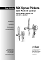
MX Sprue Pickers
with PC-E IV control
Models MX60 to MX550, and
MX350T to MX550T
Installation
Operation
Maintenance
Troubleshooting
Instant Access
Parts and Service
(800) 458-1960
(814) 437-6861
www.conairnet.com
The Conair Group, Inc.
One Conair Drive
Pittsburgh, PA 15202
Phone: (412) 312-6000
Fax: (412)-312-6227
UGR002/1099
Record your equipment’s
model and serial number(s) and the date you
received it in the spaces
provided.
It is important to record the model and serial number(s) of
your equipment and the date you received it in the User
Guide. Our service department uses this information, along
with the manual number, to provide help for the specific
equipment you installed.
Keep this User Guide and all manuals, engineering prints and
parts lists together for documentation of your equipment.
Date:
Document Number:
UGR002/1099
Serial number(s):
Model number(s):
Power Specifications:
Amps
Volts
Phase
Cycle
DISCLAIMER: The Conair Group, Inc., shall not be liable for errors
contained in this User Guide or for incidental, consequential damages in connection with the furnishing, performance or use of this
information. Conair makes no warranty of any kind with regard to
this information, including, but not limited to the implied warranties
of merchantability and fitness for a particular purpose.
Copyright 1999
THE CONAIR GROUP, INC.
All rights reserved
INTRODUCTION . . . . . . . . . . . . . . . . . . .1-1
Purpose of the User Guide . . . . . . . . . . . . . . . . . . . . . . . . .1-2
How the Guide is Organized . . . . . . . . . . . . . . . . . . . . . . .1-2
Your Responsibilities as a User . . . . . . . . . . . . . . . . . . . . .1-2
ATTENTION: Read this so no one gets hurt . . . . . . . . . . .1-3
TABLE OF
CONTENTS
DESCRIPTION . . . . . . . . . . . . . . . . . . . .2-1
What is the Sprue Picker? . . . . . . . . . . . . . . . . . . . . . . . . .2-2
Typical Applications . . . . . . . . . . . . . . . . . . . . . . . . . . . . .2-3
Limitations . . . . . . . . . . . . . . . . . . . . . . . . . . . . . . . . . . . .2-3
How the Sprue Picker Works . . . . . . . . . . . . . . . . . . . . . . .2-4
MX Sprue Picker Features . . . . . . . . . . . . . . . . . . . . . . . . .2-5
Specifications . . . . . . . . . . . . . . . . . . . . . . . . . . . . . . . . . .2-6
Optional Equipment . . . . . . . . . . . . . . . . . . . . . . . . . . . . . .2-7
INSTALLATION . . . . . . . . . . . . . . . . . . . .3-1
Unpacking the Boxes . . . . . . . . . . . . . . . . . . . . . . . . . . . . .3-2
Preparing for Installation . . . . . . . . . . . . . . . . . . . . . . . . . .3-3
Preparing the Platen . . . . . . . . . . . . . . . . . . . . . . . . . . . . . .3-4
Positioning the Sprue Picker . . . . . . . . . . . . . . . . . . . . . . .3-5
Setting Gripper Height . . . . . . . . . . . . . . . . . . . . . . . . . . . .3-6
Connecting the Main Power Source . . . . . . . . . . . . . . . . . .3-7
Adjusting the Pivot . . . . . . . . . . . . . . . . . . . . . . . . . . . . . .3-8
Adjusting Swing Angle and Discharge Side . . . . . . . . . . . .3-9
Changing the Wrist Flip . . . . . . . . . . . . . . . . . . . . . . . . . .3-10
Adjusting the Speed . . . . . . . . . . . . . . . . . . . . . . . . . . . . .3-12
Adjusting the Sprue Verification Switch . . . . . . . . . . . . . .3-13
Verifying the Electrical Interface . . . . . . . . . . . . . . . . . . .3-14
Checking the Electrical Interface . . . . . . . . . . . . . . . . . . .3-16
Preparing for Testing . . . . . . . . . . . . . . . . . . . . . . . . . . . .3-17
Testing the Installation . . . . . . . . . . . . . . . . . . . . . . . . . . .3-17
OPERATION . . . . . . . . . . . . . . . . . . . . . .4-1
Hand Control Features . . . . . . . . . . . . . . . . . . . . . . . . . . . .4-2
Before Starting . . . . . . . . . . . . . . . . . . . . . . . . . . . . . . . . .4-3
Starting the Sprue Picker . . . . . . . . . . . . . . . . . . . . . . . . . .4-3
Viewing Information . . . . . . . . . . . . . . . . . . . . . . . . . . . . .4-4
Choosing the Mold . . . . . . . . . . . . . . . . . . . . . . . . . . . . . .4-5
Programming the Motion Sequence . . . . . . . . . . . . . . . . . .4-6
Programming Grip, Vacuum, and Home Position . . . . . . . .4-8
Monitoring Input/Output . . . . . . . . . . . . . . . . . . . . . . . . .4-10
Viewing Timer Settings . . . . . . . . . . . . . . . . . . . . . . . . . .4-11
Choosing Timer Settings . . . . . . . . . . . . . . . . . . . . . . . . .4-12
Setting Timer Values . . . . . . . . . . . . . . . . . . . . . . . . . . . .4-13
Operating Manually . . . . . . . . . . . . . . . . . . . . . . . . . . . . .4-14
Starting Automatic Operation . . . . . . . . . . . . . . . . . . . . . .4-15
UGR002/1099
MX Sprue Picker, PC-E IV Control
i
TABLE OF
CONTENTS
CONT’D
OPERATION, . . . . . . . . . . . . . . . . . . .CONT’D
Restarting Automatic Operation . . . . . . . . . . . . . . . . . . . .4-16
Answering an Alarm . . . . . . . . . . . . . . . . . . . . . . . . . . . .4-17
Stopping the Sprue Picker . . . . . . . . . . . . . . . . . . . . . . . .4-18
Emergency Stopping . . . . . . . . . . . . . . . . . . . . . . . . . . . .4-18
MAINTENANCE . . . . . . . . . . . . . . . . . . . .5-1
Maintenance Features . . . . . . . . . . . . . . . . . . . . . . . . . . . .5-2
Warnings and Cautions . . . . . . . . . . . . . . . . . . . . . . . . . . .5-2
Preventative Maintenance Schedule . . . . . . . . . . . . . . . . . .5-4
Checking Electrical Connections . . . . . . . . . . . . . . . . . . . .5-6
TROUBLESHOOTING . . . . . . . . . . . . . . . .6-1
Before Beginning . . . . . . . . . . . . . . . . . . . . . . . . . . . . . . . .6-2
A Few Words of Caution . . . . . . . . . . . . . . . . . . . . . . . . . .6-2
Identifying the Cause of a Problem . . . . . . . . . . . . . . . . . .6-2
Answering an Alarm . . . . . . . . . . . . . . . . . . . . . . . . . . . . .6-3
The Sprue Picker Does Not Cycle . . . . . . . . . . . . . . . . . . .6-4
The Mold is Not Working Properly . . . . . . . . . . . . . . . . . .6-5
The Arm is Not Working Properly . . . . . . . . . . . . . . . . . . .6-6
Strip Motion is Not Working . . . . . . . . . . . . . . . . . . . . . . .6-7
There is No Swing Motion . . . . . . . . . . . . . . . . . . . . . . . . .6-8
The Gripper Does Not Work . . . . . . . . . . . . . . . . . . . . . . .6-9
There is No Vacuum . . . . . . . . . . . . . . . . . . . . . . . . . . . . .6-10
APPENDIX . . . . . . . . . . . . . . . . . . . . . .A-1
Customer Service . . . . . . . . . . . . . . . . . . . . . . . . . . . . . . .A-1
Guarantee/Warranty . . . . . . . . . . . . . . . . . . . . . . . . . . . . .A-2
Adding a Second Descent . . . . . . . . . . . . . . . . . . . . . . . . .A-3
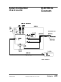
Electrical Diagrams . . . . . . . . . . . . . . . . . . . . . . . . . . . . . .A-9
System Configuration . . . . . . . . . . . . . . . . . . . . . . . . .A-9
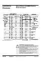
Sprue Picker and IMM Interface . . . . . . . . . . . . . . . .A-10
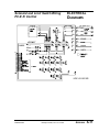
Solenoid and Limit Switch Wiring . . . . . . . . . . . . . . .A-11
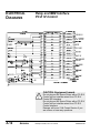
Relay and IMM Interface . . . . . . . . . . . . . . . . . . . . .A-12
Motion Sequences . . . . . . . . . . . . . . . . . . . . . . . . . . . . . .A-13
PARTS/DIAGRAMS . . . . . . . . . . . . . . .P/D-1
Your User Guide will include one of these three parts
packages, depending on the sprue picker model ordered.
Models MX60 to MX150 . . . . . . . . . . . . . . . IMR001/1099
Models MX250 to MX550 . . . . . . . . . . . . . . IMR002/1099
Models MX250T to MX550T . . . . . . . . . . . . IMR003/1099
ii
MX Sprue Picker, PC-E IV Control
UGR002/1099
INTRODUCTION
● Purpose of the User Guide . . . .1-2
● How the User Guide
is organized . . . . . . . . . . . . . . .1-2
● Your Responsibilities
as a User . . . . . . . . . . . . . . . .1-2
● ATTENTION: Read this so
no one gets hurt . . . . . . . . . . .1-3
UGR002/1099
MX Sprue Picker, PC-E IV Control
1-1
PURPOSE OF
THE USER
GUIDE
This User Guide describes the Conair MX Sprue Pickers and
explains step-by-step how to install, operate, maintain and
repair this equipment.
HOW THE USER
GUIDE IS
ORGANIZED
Symbols have been used to help organize the User Guide and
call your attention to important information regarding safe
installation and operation.
YOUR
RESPONSIBILITY
AS A USER
Before installing this product, please take a few moments to
read the User Guide and review the diagrams and safety information in the instruction packet. You also should review manuals covering associated equipment in your system. This
review won’t take long, and it could save you valuable installation and operating time later.
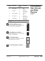
Symbols within triangles warn of conditions that could
be hazardous to users or could damage equipment.
Read and take precautions before proceeding.
1
Numbers within shaded squares indicate tasks or steps
to be performed by the user.
◆
A diamond indicates the equipment’s response to an
action performed by the user.
❒
●
An open box marks items in a checklist.
A shaded circle marks items in a list.
You must be familiar with all safety procedures concerning
installation, operation and maintenance of this equipment.
Responsible safety procedures include:
● Thorough review of this User Guide, paying particular
attention to hazard warnings, appendices and related diagrams.
● Thorough review of the equipment itself, with careful
attention to voltage sources, intended use and warning
labels.
● Thorough review of instruction manuals for associated
equipment.
● Step-by-step adherence to instructions outlined in this
User Guide.
1-2
INTRODUCTION
MX Sprue Picker, PC-E IV Control
UGR002/1099
We design equipment with the user’s safety in mind. You can
avoid the potential hazards identified on this machine by following the procedures outlined below and elsewhere in the
User Guide.
WARNING: Improper installation, operation, or servicing may result in
equipment damage or personal injury.
ATTENTION:
READ THIS
SO NO
ONE GETS HURT
This equipment should only be installed, adjusted, and serviced by qualified technical personnel who are familiar with the construction, operation, and potential hazards of this type of
machine.
All wiring, disconnects, and fuses should be
installed by qualified electrical technicians in
accordance with electrical codes in your region.
Always maintain a safe ground. Do not operate
the equipment at power levels other than what
is specified on the machine serial plate.
WARNING: Voltage hazard.
This equipment is powered by alternating current, as specified on the machine serial tag and
data plate.
A properly sized conductive ground wire from
the incoming power supply must be connected
to the chassis ground terminal inside the electrical enclosure. Improper grounding can result in
severe personal injury and erratic machine
operation.
Always disconnect and lock out the incoming
main power source before opening the electrical
enclosure or performing non-standard operating
procedures such as routine maintenance. Only
qualified personnel should perform troubleshooting procedures that require access to
the electrical enclosure while power is on.
CAUTION: Equipment hazard.
Do not plug an MX Sprue Picker with a PC-E III
Control into an interface wired for a PC-E IV
Control SPI interface.
Do not plug an MX Sprue Picker with a PC-E IV
Control into an interface wired for a PC-E III
Control interface.
Damage will occur! Call Conair Service if you
are unsure or have any questions.
UGR002/1099
MX Sprue Picker, PC-E IV Control
INTRODUCTION
1-3
DESCRIPTION
● What is the Sprue Picker? . . . . .2-2
● Typical Applications . . . . . . . . . .2-3
● Limitations . . . . . . . . . . . . . . . . .2-3
● How the Sprue Picker Works . . .2-4
● MX Sprue Picker Features . . . . .2-5
● Specifications . . . . . . . . . . . . . .2-6
● Optional Equipment . . . . . . . . . .2-7
UGR002/1099
MX Sprue Picker, PC-E IV Control
2-1
WHAT IS THE
MX SPRUE
PICKER?
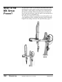
The MX Sprue Picker is a pneumatic robot that removes the
molded part or sprue runner system from the injection molding machine. Sprue pickers are mounted on a fixed platen on
the injection machine. When the mold opens, the robot arm
lowers into the mold area, grips the sprue or part and pivots to
place the item in a designated area.
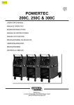
The MX Sprue Pickers are available in several models to suit
your application needs, including telescopic models when the
height of the ceiling is an issue. See Specifications, page 2-7.
MX450
MX150
2-2
DESCRIPTION
MX Sprue Picker, PC-E IV Control
UGR002/1099
Conair MX Sprue Pickers are ideal for applications requiring
quick, consistent sprue/part removal from either a moveable or
stationary platen. The robot interfaces directly with the mold
machine to ensure predictable, constant cycle times. This
allows accurate time quoting for production and maintenance
schedules.
TYPICAL
APPLICATIONS
Use the MX Sprue Pickers to eliminate common problems:
● inconsistent cycle times
● improper part/sprue separation
● unsafe sprue/part removal
Choose Conair MX Sprue Pickers based on the size of the
injection molding machine you are using.
MX Sprue Picker
MX60
MX150
MX250
MX350
MX450
MX550*
MX350T
MX550T*
LIMITATIONS
For Injection Mold
Machine Size, ton
20 to 60
60 to 150
150 to 250
150 to 350
150 to 450
150 to 550
150 to 350
150 to 550
* Contact Conair for suitability of application. Larger presses
may be accommodated.
NOTE: Use this table only as a general guide. Application
data sheet information determines the proper size of sprue
picker for your application. Consult your Conair representative for assistance when choosing a Conair MX Sprue Picker.
UGR002/1099
MX Sprue Picker, PC-E IV Control
DESCRIPTION
2-3
HOW THE
SPRUE PICKER
WORKS
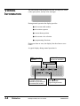
The MX Sprue Picker interfaces with the mold machine. The
hand control provides the buttons for controlling and monitoring the sprue picker. From the hand control you can:
● monitor the input/output status
● set and adjust cycle timers in both manual and automatic
mode
● adjust mode settings
● operate the picker manually
● operate the picker automatically
● store programs
The sprue picker sends a signal to the mold machine to begin
the cycle. The sprue picker receives the Mold Open signal
from the mold machine to remove the sprue/part. The robot
arm moves into the mold area, grips the part, and raises out of
the mold. The arm pivots outside the press area to release the
part/runner. The sprue picker sends a signal to the mold
machine to begin the next cycle.
Each sprue picker is equipped with a part verification switch
to stop the molding machine if a part is missed.
2-4
DESCRIPTION
MX Sprue Picker, PC-E IV Control
UGR002/1099
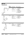
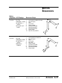
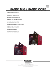
The MX Sprue Picker models have these features:
MX SPRUE
PICKER
FEATURES
Main arm cylinder
Swing arm
Arm stroke
adjustment
Oil-free swing
cylinder
Strip Cable Track
Strip cylinder
Arm height
adjustments
Arm height
adjustments
Air solenoid
valves
Ratchet lever
Filter Assembly
Gripper with runner
verification
Base
UGR002/1099
MX Sprue Picker, PC-E IV Control
DESCRIPTION
2-5
SPECIFICATIONS
MX250-550, MX350T-550T
MX60-150
MODEL
MX-60
Dimensions, in. {mm}
A-Height
47.2 {1200}
B-Width
11.4 {290}
C-Length
23.6 {600}
D-Grip Center
Above Platen
7.1 {180}
- with wrist rotation
4.7 {120}
E-Swing Point Above Platen21.9 {557}
Strip Stroke Adjustment, F to G
2-12.2
{50-310}
Strip Stroke
12.2 {75}
Performance characteristics
Injection machine size, ton 20 - 60
Swing Angle, o
45 - 90
Wrist Rotation Angle, o
90
Min. Takeout Time, sec
0.6
Min. Cycle Time, sec
3
Weight, lb {kg}
Installed
56 {25}
Shipping
81 {37}
Physical Characteristics
Air Consumption,
3 {85}
CFM {NI/cycle}
Approximate Max. Payload, lb {kg}
- w/o wrist rotation
2.2 {1}
- with wrist rotation
1.1 {0.5}
Working Air Pressure,
PSI {MPa} @ 3 CFM
80 {11.6}
Power Consumption, amps
115V/1 phase/50-60 Hz
5
220V/1 phase/50-60 Hz
2.5
MX-150
MX-250
MX-350
MX-350T
MX-450
MX-550
MX-550T
51 {1300}
11.4 {290}
28.3 {720}
67 {1700}
71 {1800} 61.0 {1550}
16.1 {410}
16.1 {410} 17.7 {450}
39.8 {1010} 39.8 {1010} 43.3 {1100}
75 {1900}
79 {2000} 65.0 {1650}
16.1 {410}
16.1 {410} 14.4 {450}
39.8 {1010} 39.8 {1010} 43.3 {1100}
7.1 {180}
4.7 {120}
21.9 {557}
15.0 {380}
7.9 {200}
30.9 {785}
15.0 {380}
9.3 {241}
30.9 {785}
12.6 {320}
7.4 {188}
30.9 {785}
15.0 {380}
9.3 {241}
30.9 {785}
15.0 {380} 12.6 {320}
9.3 {241} 7.4 {188}
30.9 {785} 30.9 {785}
2-16.9
{50-430}
16.9 {75}
3.3-21.1
{85-535}
4.9 {125}
3.3-21.1
{85-535}
4.9 {125}
2.8-20.1
{70-510}
4.9 {125}
3.3-21.1
{85-535}
4.9 {125}
3.3-21.1
{85-535}
4.9 {125}
2.8-20.1
{70-510}
4.9 {125}
60 - 150
45 - 90
90
0.7
3.2
150 - 250
45 - 90
90
1.2
3.8
150 - 350
45 - 90
90
1.3
4.0
150 - 350
45 - 90
90
1.3
4.0
150 - 450
45 - 90
90
1.4
4.2
150 - 550
45 - 90
90
1.5
4.5
150 - 550
45 - 90
90
1.5
4.5
60 {27}
85 {39}
124 {56}
154 {70}
126 {57}
156 {71}
130 {59}
160 {73}
128 {58}
158 {72}
132 {60}
162 {74}
134 {61}
164 {75}
3 {85}
3 {85}
3 {85}
3 {85}
3 {85}
3 {85}
3 {85}
2.2 {1}
1.1 {0.5}
4.4 {2}
2.2 {1}
4.4 {2}
2.2 {1}
4.4 {2}
2.2 {1}
4.4 {2}
2.2 {1}
4.4 {2}
2.2 {1}
4.4 {2}
2.2 {1}
80 {11.6}
80 {11.6}
80 {11.6}
80 {11.6}
80 {11.6}
80 {11.6}
80 {11.6}
5
2.5
5
2.5
5
2.5
5
2.5
5
2.5
5
2.5
5
2.5
*Optional
2-6
DESCRIPTION
MX Sprue Picker, PC-E IV Control
UGR002/1099
Options available on all models include:
● Second descent slowdown
Controls arm extension speed over gate (descent slowdown).
OPTIONAL
EQUIPMENT
● Second ascent slowdown
Controls arm retraction speed over gate (ascent slowdown).
● Venturi vacuum kit
Allows the use of vacuum end-of-arm tooling to remove
light duty parts.
● Sprue cutting systems
● Extended strip stroke
Extends the strip stroke travel distance for deep draw
parts (typically used with end-of-arm tooling).
● End-of-arm tooling
Used for light duty part removal.
● Grip pressure regulator
Reduces gripper pressure, preventing sprue/runner from
being squeezed flat and causing a false Missed Runner
alarm.
UGR002/1099
MX Sprue Picker, PC-E IV Control
DESCRIPTION
2-7
INSTALLATION
● Unpacking the Boxes . . . . . . . . .3-2
● Preparing for Installation . . . . . .3-3
● Preparing the Platen . . . . . . . . .3-4
● Positioning the Sprue Picker . . .3-5
● Setting Gripper Height . . . . . . . .3-6
● Connecting the Main
Power Source . . . . . . . . . . . . .3-7
● Adjusting the Pivot . . . . . . . . . .3-8
● Adjusting Swing Angle
and Discharge Side . . . . . . . . .3-9
● Changing the Wrist Flip . . . . . .3-10
● Adjusting the Speed . . . . . . . .3-12
● Adjusting the Sprue
Verification Switch . . . . . . . .3-13
● Verifying the
Electrical Interface . . . . . . . .3-14
● Checking the
Electrical Interface . . . . . . . .3-16
● Preparing for Testing . . . . . . . .3-17
● Testing the Installation . . . . . . .3-17
UGR002/1099
MX Sprue Picker, PC-E IV Control
3-1
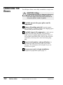
UNPACKING THE
BOXES
The MX Sprue Picker comes fully assembled in a single crate.
CAUTION: Lifting
To avoid personal injury or damage to the sprue
picker, lift the sprue picker using a forklift or
hoist with straps that have been positioned at
the sprue picker's center of gravity.
1
Carefully uncrate the sprue picker and its
components.
2
Remove all packing material, protective paper,
tape, and plastic. Compare contents to the shipping papers
to ensure that you have all the parts.
3
Carefully inspect all components to make sure no
damage occurred during shipping. If any damage is
found, notify the shipping agent immediately. Check all
wire terminal connections, bolts, and any other electrical
connections, which may have come loose during shipping.
4
Record serial numbers and specifications in
the blanks provided on the back of the User Guide's
title page. This information will be helpful if you ever
need service or parts.
5
You are now ready to begin installation.
Complete the preparation steps on page 3-3.
3-2
INSTALLATION
MX Sprue Picker, PC-E IV Control
UGR002/1099
CAUTION: Moving the Sprue Picker
When you receive the sprue picker, the swing is
bolted to prevent movement. On the MX60 to
MX150 models, a bolt goes through the swing
angle adjustment bracket into the base. This
prevents the arm from swinging.
PREPARING FOR
INSTALLATION
On the MX250 to MX450 models, there is an Lbracket between the swing casting and the
base. Leave the swing inhibitor on until the
sprue picker is mounted on the press. Remove
after mounting.
WARNING: Improper installation, operation, or servicing may result in
equipment damage or personal injury.
This equipment should only be installed, adjusted, and serviced by qualified technical personnel who are familiar with the construction, operation, and potential hazards of this type of
machine.
All wiring, disconnects, and fuses should be
installed by qualified electrical technicians in
accordance with electrical codes in your region.
Always maintain a safe ground. Do not operate
the equipment at power levels other than what
is specified on the machine serial tag and data
plate.
Plan the location. Make sure the area where the sprue picker is
installed has:
● A grounded power source. Check the sprue picker’s
serial tag for the correct amps, voltage, phase, and
cycle. All wiring should be completed by qualified personnel and comply with your region’s electrical codes.
● Clearance for safe operation and maintenance.
Make sure there is enough clearance around the sprue
picker for movement, maintenance and servicing. Be
sure the sprue picker has proper clearance to avoid
structures, utilities, overhead cranes, and loading pipes,
as well as other machines and equipment. Be sure that
the maximum envelope is clearly marked and protected
from entry by personnel during operation. The maximum envelope is the volume of space encompassing
the maximum designed movement of ALL robot parts,
including the end of arm tooling, work piece and
attachments.
UGR002/1099
MX Sprue Picker, PC-E IV Control
INSTALLATION
3-3
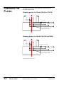
PREPARING THE
PLATEN
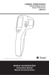
You need to drill holes in the stationary (fixed) platen to
accept the sprue picker.
Mounting pattern for Models MX60 to MX150*
4.921 (125)
2.461 (63)
1.969 (50)
0.591 (15)
2.165 (55)
3.740 (95) 7.677 (195)
6 x dia 5/16” drill x 1” dp
3/8-16 tap x 3/4” dp
Mounting pattern for Models MX250 to MX550*
6.693 (170)
3.346 (85)
2.756 (70)
0.984 (25)
3.937 (100)
6.890 (175) 7.874 (200)
6 x dia .421” drill x 1.5” dp
1/2-13 tap x 1.25” dp
*Dimensions shown are inches (mm).
3-4
INSTALLATION
MX Sprue Picker, PC-E IV Control
UGR002/1099
CAUTION: Lifting
To avoid personal injury or damage to the sprue
picker, lift the sprue picker using a hoist. Place
the straps around the swing shaft between the
strip frame and the base.
1
2
POSITIONING
THE SPRUE
PICKER
Mount an eye bolt in the eyehole.
Move the sprue picker into position.
Using a strap, hoist the sprue picker into position on the
platen.
3
Secure the sprue picker to the platen
with the supplied screws, lock washers, and flat washers.
4
Remove the swing inhibitor.
UGR002/1099
MX Sprue Picker, PC-E IV Control
INSTALLATION
3-5
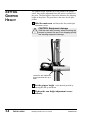
SETTING
GRIPPER
HEIGHT
The gripper height, from the top of the platen to the gripper
center, may require adjustment once the picker is mounted on
the press. The arm height is lowered to minimize the shipping
height of the picker. The procedure is the same for all sprue
pickers.
1
Hold the main arm and loosen the four arm height
adjustment screws.
CAUTION: Equipment damage
Hold the main arm securely when loosening the
screws to prevent the arm from dropping quickly
and causing equipment damage.
Loosen the four adjustment
screws and slide arm up or
down.
3-6
INSTALLATION
2
Set the gripper height to the desired position by
moving the arm up and down.
3
Tighten the arm height adjustment screws
securely.
MX Sprue Picker, PC-E IV Control
UGR002/1099
WARNING: Electrical hazard
Before performing any work on this product, disconnect and lock out electrical power sources
to prevent injury from unexpected energization
or start-up.
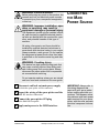
CONNECTING
THE MAIN
POWER SOURCE
WARNING: Improper installation, operation, or servicing may result in
equipment damage or personal injury.
This equipment should only be installed, adjusted, and serviced by qualified technical personnel who are familiar with the construction, operation, and potential hazards of this type of
machine.
All wiring, disconnects, and fuses should be
installed by qualified electrical technicians in
accordance with electrical codes in your region.
Always maintain a safe ground. Do not operate
the equipment at power levels other than what
is specified on the machine serial tag and data
plate.
WARNING: Crushing Injury
This device has high speed moving parts that
can cause crushing injuries. Keep body parts
and clothing away from moving parts. Always
disconnect the sprue picker from compressed
air sources before servicing.
Do not operate machine unless you are trained
and have read and understood this user guide.
1
Disconnect and lock out main power supply
to which the sprue picker will be connected.
2
Inspect the wiring of the sprue picker and the
IMM SPI interface connections.
3
Connect the sprue picker SPI plug
to the IMM SPI receptacle.
4
Apply main power to the IMM interface.
UGR002/1099
MX Sprue Picker, PC-E IV Control
IMPORTANT: Always refer to
the wiring diagrams that
came with your sprue picker
before making electrical connections. The diagrams show
the minimum size main power
cable required for your sprue
picker, and the most accurate
electrical component information.
INSTALLATION
3-7
ADJUSTING THE
PIVOT
The MX Sprue Picker strip frame can pivot to move the picker
out of the way when the mold is changed. You need to adjust
the pivot stop so that the axis of the strip frame is parallel with
the base of the press. The stop allows the picker to pivot back
into position after the mold change.
Adjust the pivot stop, if required, to compensate for any misalignment of the bolt pattern after installation.
tighten
loosen
3-8
INSTALLATION
MX Sprue Picker, PC-E IV Control
UGR002/1099
You can easily change the sprue picker/runners to release parts
to either side of the press by changing the swing cylinder
position.
WARNING: Air pressure hazard
When adjusting the swing, turn OFF compressed air to the sprue picker. Disconnect the
air supply before making any adjustments!
1
2
3
ADJUSTING
SWING ANGLE
AND DISCHARGE
SIDE
Exhaust the air supply completely.
Loosen the Swing Adjustment nut.
Set the direction and the angle
by moving the cylinder mounting in the bracket slot.
4
Tighten the nut securely after the adjustment.
Swing flow
controls
Swing
Adjustment
nut
Operator side
discharge
UGR002/1099
Non-operator
side discharge
MX Sprue Picker, PC-E IV Control
INSTALLATION
3-9
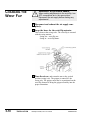
CHANGING THE
WRIST FLIP
WARNING: Air pressure hazard
When making adjustments to the wrist flip, turn
OFF compressed air to the sprue picker.
Disconnect the air supply before making any
adjustments!
1
Disconnect and exhaust the air supply completely.
2
Swap the hoses for the wrist flip actuator.
This is done at the swing valve. The wrist flip is actuated
with the swing motion:
Swing out = wrist flip out
Swing in = wrist flip home.
3
3-10
INSTALLATION
Turn the air on and return the arm to the vertical
position (swing is in). The gripper is rotated 90° the
wrong way. The gripper must now be repositioned on the
wrist flip actuator to bring the gripper assembly into the
proper orientation.
MX Sprue Picker, PC-E IV Control
UGR002/1099
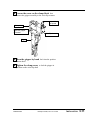
4
Loosen the screw on the clamp block that
secures the gripper assembly to the wrist flip actuator.
Adjust Wrist
Flip speed
Clamp block
Loosen this screw to
adjust the gripper
orientation.
Wrist Flip Actuator
Gripper
5
Turn the gripper by hand back into the position
shown above.
6
Tighten the clamp screw to lock the gripper in
position on the wrist flip shaft.
UGR002/1099
MX Sprue Picker, PC-E IV Control
INSTALLATION
3-11
The flow controls are used to adjust the picker speeds. You
can adjust the Strip Action flow controls, the Arm Down flow
control, and the Swing Motion flow controls.
ADJUSTING THE
SPEED
Loosen lock nut and turn the flow control knobs clockwise to
slow the picker. Turning the controls counter-clockwise causes
the picker to speed up. Tighten the lock nut after making
adjustments.
Swing flow
controls
Strip Stroke
flow controls
Arm
Down
flow
control
Swing flow
controls
Strip Stroke
flow controls
MX250-MX550
Arm Down
flow control
MX60-MX150
3-12
INSTALLATION
MX Sprue Picker, PC-E IV Control
UGR002/1099
To ensure proper part/sprue verification, adjust the LS-4
switch.
1
Use the manual grip key to cycle the gripper
open and closed while in the mold area or over the gate
area.
2
Place a sprue into the open gripper jaws and
ADJUSTING THE
SPRUE
VERIFICATION
SWITCH
manually grip the sprue with the gripper.
3
Adjust the LS-4 proximity sensor to achieve the
following:
Gripper open
LS-4 off
4
Gripper with
Sprue
LS-4 on
Gripper closed
LS-4 off
Loosen and slide the switch on the gripper.
Adjust it to achieve the conditions show above.
5
When adjusted, tighten the switch securely.
NOTE: Check this verification regularly to ensure the
picker is correctly verifying the part/sprue removal. The
adjustment may need reset if the sprue diameter
changes (due to mold changes). If the gripper crushes
the sprue completely, an optional grip regulator can be
added to decrease the pressure used to grip the sprue.
UGR002/1099
MX Sprue Picker, PC-E IV Control
INSTALLATION
3-13
VERIFYING THE
ELECTRICAL
INTERFACE
Electrical Diagrams are in
the Appendix, beginning
on page A-9.
The electrical interface between the sprue picker and the injection molding machine is the most important part of the installation. The interface must function correctly to maintain the
safety of the sprue picker and the mold. As a result, the interface must be verified.
CAUTION: Equipment hazard.
Do not plug an MX Sprue Picker with a PC-E III
Control into an interface wired for a PC-E IV
Control SPI interface.
Do not plug an MX Sprue Picker with a PC-E IV
Control into an interface wired for a PC-E III
Control interface.
Damage will occur! Call Conair Service if you
are unsure or have any questions.
The areas that must be verified as functional and correct are
the motion controls and the inputs.
Verifying motion controls (permissives)
The control of the clamp movements is critical. The sprue
picker must control the following motions for safety. Check
the following movements:
● Mold Close
The sprue picker must control the closing motion of
the mold. If the sprue picker is not clear of the mold
area, the press close must be inhibited. Also, if the
sprue picker misses a part, the press must be inhibited from closing.
● Mold Open
The opening of the mold must be controlled by the
sprue picker. If the arm is not in a safe area - Fully
Up or Outside the press area - the injection molding
machine should not be permitted to open.
● Mold Ejection (Forward)
The ejection of the part can be controlled by the
sprue picker. This ensures the proper placement of
the sprue picker gripper before the sprue/runner is
ejected.
● Cycle Start (optional)
This option sends a signal from the sprue picker to
the IMM after the mold closes to tell the IMM to
begin a new cycle.
3-14
INSTALLATION
MX Sprue Picker, PC-E IV Control
UGR002/1099
Verifying the Inputs
The first four inputs must be verified. The others are optional
depending on the application.
Verify the following inputs as functional and correct:
● Mold Full Open
This signal starts the sprue picker into the mold
area. This is a very important signal. If the sprue
picker enters, or attempts to enter the mold at the
wrong time, damage to the arm and/or mold can
occur.
● Mold Full Closed
This signal is sent to the sprue picker when the mold
is fully closed or locked up.
● Press Gate Closed
This signal tells the sprue picker that the safety gate
is closed.
● Press Auto
The sprue picker must see this signal to cycle automatically.
● E-Stop from IMM
The sprue picker monitors the emergency stop message from the IMM. If the sprue picker senses the
message from the IMM, the sprue picker stops.
● Reject Part
The IMM signals the sprue picker there is a rejected
part. The sprue picker grabs the part, strips it and
immediately releases it without moving it outside.
UGR002/1099
MX Sprue Picker, PC-E IV Control
INSTALLATION
3-15
CHECKING THE
ELECTRICAL
INTERFACE
WARNING
This verification is critical. The sprue picker
must control these for safety concerns.
To check the Open/Close permissives:
1
With the arm above the mold remove the inputs
for Arm is Full Up (LS-3) or Unit Outside Clear/Fully
Out. This will make the robot appear to be in an unsafe
condition.
2
With these inputs disabled, attempt to open and
close the mold.
CAUTION
If the mold moves at all, the sprue picker is not
controlling the press movement, the interface is
not correct. Do not attempt to run the sprue
picker under this condition. The situation needs
correction! Do not just remove the interlock
relays and assume that this is verification
enough. This gives no indication of the output
status of the permissive. Perform all the steps
listed here.
3
Isolate the power of the press from the sprue picker’s power by the use of relays.
4
Do not use the relays in the PC-E IV control
to interrupt press solenoids directly. Use isolation relays
with adequate amp capacity for this purpose.
5
The inputs from the press to the sprue picker
should provide dry contact closures to allow the robot to
send its own voltage to the contact and use this voltage to
power the input.
3-16
INSTALLATION
MX Sprue Picker, PC-E IV Control
UGR002/1099
1
Make sure all components are installed according
to assembly drawings. Make sure that all bolts on the
sprue picker have been tightened.
2
PREPARING
TESTING
FOR
Check that sprue picker is firmly locked into
position with the anchoring screws.
3
Check that all wiring conforms to electrical
codes, and all wiring covers are in place.
1
Plug in the main power cord and turn on the main
disconnect. The display should fully illuminate and perform its bootup routine.
2
TESTING THE
INSTALLATION
Check that the E-Stop button is in
the out, extended position.
Turn the E-Stop button clockwise (in the
direction of the arrows) to verify that the
button is in the out, extended position.
3
Move mold to Full Open position
with the IMM in manual mode.
4
Press the Stop button.
This places the control in the Stop mode.
5
6
Press the Manual button.
Cycle the sprue picker
by pressing the movement control buttons.
7
Adjust the flow controls for smooth operation.
If the sprue picker is not working properly at any time, turn it
off immediately and refer to the Troubleshooting section of
this User Guide.
If you do not encounter any problems during testing, proceed
to the Operation section.
UGR002/1099
MX Sprue Picker, PC-E IV Control
INSTALLATION
3-17
OPERATION
● Hand Control Features . . . . . . .4-2
● Before Starting . . . . . . . . . . . . . .4-3
● Starting the Sprue Picker . . . . .4-3
● Viewing Information . . . . . . . . . .4-4
● Choosing the Mold . . . . . . . . . .4-5
● Programming the
Motion Sequence . . . . . . . . . .4-6
● Programming Grip, Vacuum,
and Home Position . . . . . . . . .4-8
● Monitoring Input/Output . . . . .4-10
● Viewing Timer Settings . . . . . .4-11
● Choosing Timer Settings . . . . .4-12
● Setting Timer Values . . . . . . . .4-13
● Operating Manually . . . . . . . . .4-14
● Starting Automatic
Operation . . . . . . . . . . . . . . . .4-15
● Restarting Automatic
Operation . . . . . . . . . . . . . . . .4-16
● Answering an Alarm . . . . . . . .4-17
● Stopping the Sprue Picker . . . .4-18
● Emergency Stopping . . . . . . . .4-18
UGR002/1099
MX Sprue Picker, PC-E IV Control
4-1
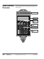
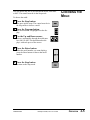
HAND CONTROL
FEATURES
The sprue picker control has several features that allow you to
input setup information, monitor input/output, change modes,
and view errors.
Emergency Stop
LED display
Stop button
Auto Recycle
button
Programming
buttons
Numeric keypad
Motion Control
buttons
4-2
OPERATION
MX Sprue Picker, PC-E IV Control
UGR002/1099
Before you start daily operation of the sprue picker, perform
preventative maintenance. This incudes daily, weekly, monthly
and semi-annual maintenance. Maintenance procedures are
described in the Maintenance section of this Users Guide,
beginning on page 5-1.
BEFORE
STARTING
WARNING: Be sure that power to the sprue
picker is disconnected and locked out when
doing any maintenance on it. Follow all safety
rules when performing any maintenance on this
equipment.
The power must be on for any picker or press operations to
occur.
Off Mode
STARTING THE
SPRUE PICKER
When the picker is in the Off position, the press operates
without the sprue picker. The interlock signals for the
mold are released. The interlocks are still monitored,
however, to ensure the picker is in a safe position for
opening and closing the mold.
NOTE: When in the Off mode, the sprue picker does not
remove parts/sprues from the press. The operator must do
it.
On Mode
In the On position the picker runs with the press. The
operator can cycle the picker in either manual mode or
automatic mode.
UGR002/1099
MX Sprue Picker, PC-E IV Control
OPERATION
4-3
VIEWING
INFORMATION
The LED on the control displays the data you input, the status
of the sprue picker, and any error messages.
During normal operation the display provides:
● the current mold number
● the motion sequence
● current home position
● the current valve selection
● programming directions
During an alarm or error, the display lists the alarm or error
codes.
A typical display during normal operation is:
GRIPS:GRP - the grip
and vacuum selections
MLBX - the motion
sequence
O - Home position
M01 - the current mold number. Control can be programmed for up to seven different molds, M01 to M07.
4-4
OPERATION
MX Sprue Picker, PC-E IV Control
press
ENT. Programming directions
UGR002/1099
You can choose any one of seven different molds, from M01
to M07. The control must be in the Stop mode.
To choose the mold:
1
CHOOSING THE
MOLD
Press the Stop button.
The sprue picker stops. The control must be in
the Stop mode to choose a mold.
2
Press the Program button.
The mold number is highlighted on the display.
3
Use the Up and Down arrows
to move sequentially through the mold numbers, M01 to M07. Each mold number displays with each press of the arrows.
4
Press the Enter button.
When the mold number you want displays,
press the Enter button to choose that mold
number.
5
Press the Stop button
to return to the Stop mode.
UGR002/1099
MX Sprue Picker, PC-E IV Control
OPERATION
4-5
PROGRAMMING
THE MOTION
SEQUENCE
To view the program motion
sequence patterns, see
Motion Sequences in the
Appendix, beginning on page
A-13.
Before choosing the various motion sequences, be sure you
have chosen the appropriate mold number (see Choosing the
Mold, page 4-5).
Decide which movements you wish the sprue picker to make.
Four different movements can be programmed.
There are two choices for each of the four letters of the
motion sequence.
Motion sequence
Pick up position
the position from which the
sprue picker grips the part
Main grip release - the position
when the grip releases the part
M L 3 K
Vertical motion - the vertical
movement of the arm
Vacuum release - choose
when the vacuum releases
Choose the sequence position:
Sequence Position
Pick up position
Vertical motion
Main grip release
Choose
m*
f
L*
U
2*
K
3
M
Vacuum release
2*
K
3
M
Pick up from Moveable mold
Pick up from Fixed mold
Lower vertical motion sequence
Upward vertical motion sequence
Second extend. Grip release at
arm second extend.
Second extend and strip. Grip
release at arm second extend
and strip motion.
On the way third. Part released
on the way arm third extended.
In mold. Part release in the mold
area.
Second extend. Vacuum release
at arm second extend.
Vacuum release at second arm
extended and trip motion.
On the way 3rd descend. Vacuum
release on the way arm third
extended.
In mold. Vacuum release in mold
area (strip back end).
*Default position.
4-6
OPERATION
MX Sprue Picker, PC-E IV Control
UGR002/1099
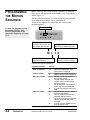
Program the motion sequence when in the Stop mode. To program the motion sequence:
1
Press Stop button. The control goes to Stop
mode.
2
Press Program button. The current motion
PROGRAMMING
THE MOTION
SEQUENCE
CONT’D
sequence information displays.
3
Use the Up and Down arrows
To view the program
motion sequence patterns, see Motion
Sequences in the
Appendix, beginning on
page A-13.
to move sequentially through the mold sequence
positions. Each mold sequence position underlines each time the Up or Down arrow is
pressed.
4
Use the Move Right arrow to toggle
between the choices for that motion sequence
position. Each time the arrow is pressed, the cursor moves to the next letter/number and underlines it.
5
Continue to move through the motion
sequence positions using the Up/Down arrows
and the Move Right arrow until you make all
your choices.
6
Press the Enter button.
After making all of your choices for the motion
sequence, press the Enter button to program your
choice.
7
Press the Stop button.
To continue, press the Stop button.
UGR002/1099
MX Sprue Picker, PC-E IV Control
OPERATION
4-7
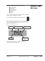
PROGRAMMING
GRIP, VACUUM,
AND HOME
POSITION
After choosing the mold number (see Choosing the Mold,
page 4-5) and programming the motion sequence (see
Programming the Motion Sequence, page 4-6) you need to
program the grip, vacuum, and home position.
Home position
Grips and
Vacuum selection
The choices include:
I
O
Home position above mold
Home position outside mold
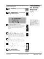
To program the home position:
1
Press the Stop button.
The control goes to Stop mode.
2
Press the Function button.
The current Functions positions display for the
chosen mold number.
Current mold
number
Function choice
3
Function number
and description
Choose the function and function choices
you want for the mold number listed on the display. The
functions and function choices for each include:
4-8
OPERATION
MX Sprue Picker, PC-E IV Control
UGR002/1099
Function Description
Function
choices
Description
f0:
Grip solenoid
a:
b:
with*
without
f1:
Grip verify
a:
b:
with switch*
without switch
f2:
Vacuum solenoid
a:
b:
without*
with
f3:
Vacuum verify
a:
b:
with switch*
without switch
f4:
Home position
a:
b:
above mold*
outside mold
PROGRAMMING
GRIP, VACUUM
AND HOME
POSITION
CONT’D
*Default setting
4
Use the Up and Down arrows
5
Use the right arrow to choose
6
Press the Enter button.
7
Press the Stop button to continue.
to scroll through the functions, f0 through f4.
The current function is highlighted.
the function choices (a, b). The current function choice is highlighted.
After you make your choicse press the Enter
button to program your choices.
UGR002/1099
MX Sprue Picker, PC-E IV Control
OPERATION
4-9
MONITORING
INPUT/OUTPUT
You can monitor the status of all inputs and outputs between
the sprue picker and the injection molding machine. The
input/output display can be viewed when the sprue picker is in
Automatic mode or Manual mode.
To view input/output, press the Monitor Input/
Output button (Mon I/O).
The LCD displays input information (LS) and output information (SOL):
where X shows which switches/valves are OFF and O shows
which ones are ON.
Input/Output
Description
LS1
LS2
LS3
LS4
LSP
LSD
Swing outward end proximity switch
Swing inward end proximity switch
Main arm retract end proximity switch (arm up)
Part (grip) verification switch
Vacuum differential switch
Main arm extend end proximity switch
LSA
LSR
LSG
LSC
LSO
LSU
LSH
Press in auto signal
Rejected part signal
Gate guard signal
Mold fully closed signal
Mold fully open signal
Sprue picker ON/OFF signal
Sprue picker home position signal
SOL1
SOL2
SOL3
SOL4
SOL5
SOL6
SOLB
Swing outward solenoid valve
Swing inward solenoid valve
Main arm extend/retract solenoid valve
Strip forward-backward solenoid valve
Main arm grip solenoid valve
Vacuum solenoid valve
Option solenoid valve
SOLS
SOLE
SOLT
Mold area free; permit clamp motion output
Permit ejector forward output
Emergency stop from sprue picker output
Press the Mon I/O button again to return to the previous control display.
4-10
OPERATION
MX Sprue Picker, PC-E IV Control
UGR002/1099
The sprue picker allows you to set time delays for:
●
●
●
●
●
●
arm movements
part ejection
grip and vacuum
cycle monitor
options
alarms
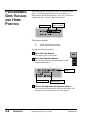
VIEWING TIMER
SETTINGS
Up to 15 different timers can be set. Timers can be fine tuned
while the picker is running in Automatic.
To view the timer settings, press the Forward button.
The current timer settings display, one at a time, on the display. Scroll through the timer settings by pressing the Forward
button (see table, page 4-13).
The timer setting displays as:
M01 the mold
number
TIM 00 the timer
setting number
(Timer Setting) tells which
mode the control is displaying
1ST DOWN DLY. - short
description of timer setting
00.50 is the set time, in
seconds, to the second
decimal place
Choose the timer setting you want from the table. See
Choosing Timer Settings, page 4-12.
UGR002/1099
MX Sprue Picker, PC-E IV Control
OPERATION
4-11
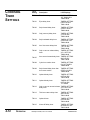
CHOOSING
TIMER
SETTINGS
4-12
OPERATION
Timer
Setting
Description
LCD Displays
TIM00
First down delay
TIMERS SETTING
1ST DOWN DLY.
TIM00 ##.##
TIM 01
Eject delay timer
TIMERS SETTING
EJECTOR DLY.
TIM01 ##.##
TIM 02
Strip forward delay timer
TIMERS SETTING
STRIP F/W DLY.
TIM02 ##.##
TIM 03
Grip (vacuum) delay timer
TIMERS SETTING
V+G ON DLY.
TIM03 ##.##
TIM 04
Strip backward delay timer
TIMERS SETTING
STRIP B/W DLY.
TIM04 ##.##
TIM 05
Arm first retract delay timer
TIMERS SETTING
1 ST UP DLY.
TIM05 ##.##
TIM 06
Grip or vacuum release delay
timer
TIMERS SETTING
V/G 1 OFF DLY.
TIM06 ##.##
TIM 07
Arm second retract delay timer TIMERS SETTING
2ND UP DLY.
TIM07 ##.##
TIM 08
Cycle time monitor timer
TIMERS SETTING
CYCLE TIM DLY.
TIM08 ##.##
TIM 09
Strip forward delay timer after
arm retract motion
TIMERS SETTING
STRIP O/W DLY.
TIM09 ##.##
TIM 10
Optional delay timer
TIMERS SETTING
OPTION DLY.
TIM10 ##.##
TIM 11
Optional delay timer
TIMERS SETTING
OPTION DLY.
TI11 ##.##
TIM 12
Grip or vacuum second release TIMERS SETTING
V/G 2 OFF DLY.
delay timer
TIM12 ##.##
TIM 13
Third arm retract delay timer
TIMERS SETTING
3RD UP DLY.
TIM13 ##.##
TIM 14
Optional timer
TIMERS SETTING
OPTION DLY.
TIM14 ##.##
TIM 15
Alarm Off delay timer
TIMERS SETTING
ALARM OFF DLY.
TIM15 ##.##
MX Sprue Picker, PC-E IV Control
UGR002/1099
Timer values can be set and changed while the sprue picker is
in operation, or when the sprue picker is stopped.
To set the timers:
1
Press the Time button.
2
Press the Up and Down buttons
SETTING TIMER
VALUES
to scroll to the chosen timer setting (TIM00 to
TIM15).
3
Press the Forward button
The cursor displays under the first number to
move the cursor to the next digit on the screen.
4
Enter the new timer value.
Press the number for the timer value you want to
set. The cursor moves to the next digit automatically.
5
Press the Enter button. The control accepts
the entries and returns to the previous display
screen.
UGR002/1099
MX Sprue Picker, PC-E IV Control
OPERATION
4-13
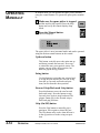
OPERATING
MANUALLY
In manual mode you can operate the sprue picker manually
using the control buttons. To operate the sprue picker manually:
1
Make sure the sprue picker is stopped
2
Press the Manual button.
and the mold is fully opened. Press the Stop
button and verify the control displays Stop
Mode.
The LCD displays:
The sprue picker is now in manual mode and can be operated
using the motion control buttons on the control.
Up/down button
This button vertically moves the main arm up
and down (extends and retracts). Press once
to extend the arm; press again to retract. The
gripper can grip in the down position, but
does not grip in the up position.
Swing button
Use this button to swing the arm outward and
to swing the arm inward. The arm can swing
from the up, forward, and backward positions, but not from the down position.
Forward Strip/Backward Strip button
Press this button to move the arm forward
backward (strip). Press the button to strip
forward; press again to strip backward. The
gripper cannot grip in the forward strip or
backward grip positions.
Grip (On/Off) button
Press the Grip button to manually grip a
part/sprue. Press again to release the part.
The Grip button only works when the arm is
in the up position or in the swing out position.
4-14
OPERATION
MX Sprue Picker, PC-E IV Control
UGR002/1099
Before placing the sprue picker into automatic operation, the
Auto signal from the press must be present for the sprue picker to run. To start automatic operation:
Press the Stop button.
The sprue picker stops. If the arm is not in the
Home position, press the Manual button and
move the arm to the Home position, then press
the Stop button.
STARTING
AUTOMATIC
OPERATION
Press the Auto/Recycle button.
The control displays the auto mode information
and the sprue picker begins automatic cycling.
CAUTION
Press the Auto/Recycle button only when the
sprue picker is stopped and in the home position. If the button is pressed at any other time in
the cycle of the sprue picker:
● The sprue picker stops
● The alarm sounds
● The error code displays on the hand control
Press the Stop button to silence the alarm.
UGR002/1099
MX Sprue Picker, PC-E IV Control
OPERATION
4-15
RESTARTING
AUTOMATIC
OPERATION
To restart the automatic operation cycle when the sprue picker
stops due to a part/sprue pickup failure:
1
Open the safety door and verify that there is no
part/sprue in the mold. If there is, remove it manually.
CAUTION: Clearing mold area.
It is the responsibility of the operator to verify
that the mold area is clear after a missed parts
condition. Follow all warnings and precautions
for the mold machine before removing parts.
Do not enter maximum envelope area while
machine is operating.
2
3
4
Press the Stop button.
Press the Manual button.
Use the Motion Control buttons
to return the main arm to the home position.
5
4-16
OPERATION
Press the Auto/Recycle button
The sprue picker begins automatic operation and the LCD
displays the Auto Mode message:
MX Sprue Picker, PC-E IV Control
UGR002/1099
When an error occurs during operation, the sprue picker stops,
an alarm sounds and the error code displays on the hand control. Press the Stop button to silence the alarm. Check this
table for a description of the error:
Error Display
Area of problem
LS1 SWITCH ERROR
OR NOT ACTUATED
CHECK LS1 SWITCH
LS-1 swing-out proximity switch error or
the switch was not actuated.
LS2 SWITCH ERROR
OR NOT ACTUATED
CHECK LS2 SWITCH
LS-2 swing-in proximity switch error or the
switch was not actuated.
LS3 SWITCH ERROR
OR NOT ACTUATED
CHECK LS3 SWITCH
LS-3 arm-up proximity switch error or the
switch was not actuated.
LS4 SWITCH ERROR
OR NO PARTS VERIF.
CHECK LS4 SWITCH
LS-4 part (grip) verification switch error or
the switch was not actuated.
TIMER#08 ERROR
CYCLE TIM EXCEEDED
CHECK TIM 08
The Timer 08 cycle time is over.
LSO SWITCH ERROR
OR INTERUP. SIGNAL
CHECK LSO SWITCH
LS-O mold fully open switch error.
LSD SWITCH ERROR
OR NOT ACTUATED
CHECK LSD SWITCH
LS-D arm descend end proximity switch
error or the switch was not actuated.
LSG SWITCH ERROR
OR NOT ACTUATED
CHECK LSG SWITCH
LS-G safety gate signal error.
LSP SWITCH ERROR
OR NOT ACTUATED
CHECK LSP SWITCH
LS-P vacuum verification switch error or
the switch was not actuated.
LSH SWITCH ERROR
OR NOT IN HOME
CHECK LSH SWITCH
LS-H robot home position switch error or
sprue picker not at home position.
OUTPUT SHORT
Short circuit in the solenoid valve(s) output
circuit.
ANSWERING
ALARM
AN
Go to the Troubleshooting section of this User Manual to correct any problems.
UGR002/0501
MX Sprue Picker, PC-E IV Control
OPERATION
4-17
STOPPING THE
SPRUE PICKER
To stop the sprue picker from either Auto mode
or Manual mode, press the Stop button.
The LCD displays the message:
EMERGENCY
STOPPING
If, at any time, you need to immediately stop the
sprue picker, press the Emergency stop button.
The sprue picker stops immediately. The control
displays:
After the emergency is handled, reset the control by turning
the E-stop button in the direction of the arrows (clockwise).
Press the Stop button to place the sprue picker in Stop mode.
Continue operation by then pressing the Auto/Recycle button
or the Manual button.
4-18
OPERATION
MX Sprue Picker, PC-E IV Control
UGR002/1099
MAINTENANCE
● Maintenance Features . . . . . . . .5-2
● Warnings and Cautions . . . . . . .5-2
● Preventative Maintenance
Schedule . . . . . . . . . . . . . . . . .5-4
● Checking Electrical
Connections . . . . . . . . . . . . . .5-6
UGR002/1099
MX Sprue Picker, PC-E IV Control
5-1
MAINTENANCE
FEATURES
The MX Sprue Picker models need regular, scheduled maintenance for peak performance. Among the features that require
maintenance are:
❐ Mechanical parts
❐ Electrical parts
WARNINGS
CAUTIONS
AND
To maintain the best performance of the sprue picker, it must
be inspected regularly. Maintenance includes a daily, weekly,
quarterly, and semi-annual (every 6 months) schedule.
Use this maintenance schedule as a guide. You may need to
shorten the time of the maintenance schedule, depending on
how often you use the sprue picker.
Follow all precautions and warnings when working on the
equipment.
WARNING: Improper installation,
operation, or servicing may result in
equipment damage or personal injury.
This equipment should only be installed, adjusted, and serviced by qualified technical personnel who are familiar with the construction, operation, and potential hazards of this type of
machine.
Be sure the sprue picker has proper clearance
to avoid structures, utilities, overhead cranes,
material hoppers and loading pipes, as well as
other machines and equipment.
Be sure that the maximum envelope is clearly
marked and protected from entry by personnel
during operation. The maximum envelope is the
volume of space encompassing the maximum
designed movement of ALL robot parts, including the end of arm tooling, work piece and
attachments.
5-2
MAINTENANCE
MX Sprue Picker, PC-E IV Control
UGR002/1099
WARNING: Voltage Hazard
This equipment is powered by alternating current, as specified on the machine serial tag and
data plate.
Device must be properly grounded. Improper
grounding can result in severe personal injury
and erratic machine operation.
Always disconnect and lock out the incoming
main power source to the sprue picker before
performing non-standard operating procedures
such as routine maintenance. Only qualified
personnel should perform troubleshooting procedures that require access to the electrical
enclosure while power is on.
All wiring, disconnects, and fuses should be
installed by qualified electrical technicians in
accordance with electrical codes in your region.
Always maintain a safe ground. Do not operate
the equipment at power levels other than what
is specified on the machine serial plate.
WARNING: High speed moving parts.
Do not enter maximum envelope area while
machine is operating. The maximum envelope
is the volume of space encompassing the maximum designed movement of ALL robot parts,
including the end of arm tooling, work piece and
attachments.
Do not operate machine unless interlocks/safety
devices are in place and function properly.
Sprue picker may drop load. Do not walk under
robot/ load. Failure to follow instructions could
result in injury.
UGR002/1099
MX Sprue Picker, PC-E IV Control
MAINTENANCE
5-3
PREVENTATIVE
MAINTENANCE
SCHEDULE
To maintain the best performance, follow this maintenance
schedule.
● Daily
❒ Inspecting filter regulator unit
Check the bowl for water and contamination and for
correct pressure.
❒ Checking hoses and cables
Check for kinks, cuts, and tears. Replace as needed.
❒ Inspecting shock absorbers and cushions
Make sure they are operating smoothly.
❒ Checking gripper return spring
Check that the gripper return spring is operating properly.
❒ Checking residue buildup
Inspect the shafts and gripper for buildup of plastic
residue. Clean as necessary.
❒ Checking interlock functions
Make sure the interlock functions are working properly.
❒ Checking part verification
Check that the parts verification is working properly.
● Weekly, or as often as needed.
❒ Inspecting fittings and mounting hardware
Check all fittings, screws, and component mounting
hardware for tightness. Tighten as needed.
❒ Checking gripper mounting screw
Check the gripper mounting screw for tightness.
Tighten as needed.
❒ Inspecting grease fittings
Check grease fittings and grease with lithium soap
grease No. 1 or 2, as needed.
❒ Checking the safety latch cylinder
Make sure the safety latch cylinder is working properly.
❒ Testing the Emergency Stop button
Verify that the emergency stop works properly.
5-4
MAINTENANCE
MX Sprue Picker, PC-E IV Control
UGR002/1099
❒ Checking angle of rotation
Check for correct angle of rotation of the arm. Adjust
as necessary.
❒ Checking timer settings
Check that settings have not changed. Adjust as needed.
PREVENTATIVE
MAINTENANCE
SCHEDULE
❒ Verifying sequence
Check that sprue picker is performing the correct
sequences. Correct as needed.
● Monthly
❒ Inspecting the filter regulator
Check that the filter regulator is set at the correct pressure. Check the filter and clean or replace it as needed.
❒ Checking the solenoid valves
Check that the solenoid valves are working properly.
Replace as needed.
❒ Inspecting the gripper for wear
Check the gripper fingers for wear. Replace as needed.
❒ Checking the exhaust filter
Check the filter and clean or replace it as needed.
❒ Examining the suction cups
If equipped with end-of-arm tooling, inspect the suction cups and replace if worn or damaged.
❒ Inspecting electrical terminals
Check all electrical terminals for tightness; adjust as
needed. See Checking Electrical Connections, page 56.
❒ Checking all electrical cables
Inspect all electrical cables for cuts, burns, and abrasions. Replace as needed.
❒ Inspecting hand pendant display
Check to make sure no LCD display is functioning
correctly. Replace as needed.
UGR002/1099
MX Sprue Picker, PC-E IV Control
MAINTENANCE
5-5
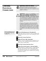
CHECKING
ELECTRICAL
CONNECTIONS
WARNING: Electrical hazard
Before performing any work on this product,
disconnect and lock out electrical power
sources to prevent injury from unexpected energization or start-up.
WARNING: Improper installation, operation, or servicing may result in
equipment damage or personal injury.
This equipment should only be installed, adjusted, and serviced by qualified technical personnel who are familiar with the construction, operation, and potential hazards of this type of
machine.
All wiring, disconnects, and fuses should be
installed by qualified electrical technicians in
accordance with electrical codes in your region.
Always maintain a safe ground. Do not operate
the equipment at power levels other than what
is specified on the machine serial tag and data
plate.
Electrical Diagrams are in
the Appendix, beginning
on page A-9.
1
Be sure the main power is disconnected
and the sprue picker is locked out. Always disconnect and
lock out the main power source before opening the unit or
servicing.
2
3
Open the electrical enclosure.
Inspect all wires and connections.
Look for loose wires, burned contacts, and signs of overheated wires. Have a qualified electrician make any necessary repairs or replacements.
4
5
Close the electrical enclosure door.
Inspect the exterior power cords and cables.
Cords should not be crimped, exposed, or rubbing against
the frame. If the interface cable or hand pendant cable
runs along the floor, make sure it is not positioned where
it could rest in pooling water or could be run over and cut
by wheels or casters.
5-6
MAINTENANCE
MX Sprue Picker, PC-E IV Control
UGR002/1099
TROUBLESHOOTING
● Before Beginning . . . . . . . . . . . .6-2
● A Few Words of Caution . . . . . .6-2
● Identifying the
Cause of a Problem . . . . . . . . .6-2
● Answering an Alarm . . . . . . . . .6-3
● The Sprue Picker Does
Not Cycle . . . . . . . . . . . . . . . . .6-4
● The Mold is Not
Working Properly . . . . . . . . . . .6-5
● The Arm is Not
Working Properly . . . . . . . . . . .6-6
● Strip Motion is
Not Working . . . . . . . . . . . . . . .6-7
● There is No Swing Motion . . . . .6-8
● The Gripper Does Not Work . . . .6-9
● There is No Vacuum . . . . . . . . .6-10
UGR002/1099
MX Sprue Picker,
6-1
BEFORE
BEGINNING
You can avoid most problems by following the recommended
installation, operation and maintenance procedures outlined in
this User Guide. If you have a problem, this section will help
you determine the cause and tell you how to fix it.
Find any wiring, parts, and assembly diagrams that were
shipped with your equipment. The diagrams will note any custom features or options not covered in this User Guide.
Verify that you have all instructional materials related to the
sprue picker. Additional details about troubleshooting and
repairing specific components are found in these materials.
Check that you have manuals for other equipment connected
in the system. Troubleshooting may require investigating other
equipment connected with the sprue picker.
A FEW WORDS
OF CAUTION
WARNING: Improper installation, operation, or servicing may result in
equipment damage or personal injury.
This equipment should only be installed, adjusted, and serviced by qualified technical personnel who are familiar with the construction, operation, and potential hazards of this type of
machine.
All wiring, disconnects, and fuses should be
installed and adjusted by qualified electrical
technicians in accordance with electrical codes
in your region. Always maintain a safe ground.
Do not operate the equipment at power levels
other than what is specified on the machine
serial tag and data plate.
WARNING: Electrical hazard
Before performing maintenance or repairs on
this product, disconnect and lock out electrical
power sources to prevent injury from unexpected energization or start-up.
IDENTIFYING THE
CAUSE OF A
PROBLEM
The Troubleshooting section covers problems directly related
to the operation and maintenance of the sprue picker. This section does not provide solutions to problems that originate with
other equipment. Additional troubleshooting help can be
found in manuals supplied with the other equipment.
6-2
MX Sprue Picker, PC-E IV Control
TROUBLESHOOTING
UGR002/1099
When an error occurs during operation, the sprue picker stops,
an alarm sounds and the error code displays on the hand control. Press the Stop button to silence the alarm. Check this
table for a description of the error:
Error Display
Area of problem
LS1 SWITCH ERROR
OR NOT ACTUATED
CHECK LS1 SWITCH
LS-1 swing-out proximity switch error or
the switch was not actuated.
LS2 SWITCH ERROR
OR NOT ACTUATED
CHECK LS2 SWITCH
LS-2 swing-in proximity switch error or the
switch was not actuated.
LS3 SWITCH ERROR
OR NOT ACTUATED
CHECK LS3 SWITCH
LS-3 arm-up proximity switch error or the
switch was not actuated.
LS4 SWITCH ERROR
OR NO PARTS VERIF.
CHECK LS4 SWITCH
LS-4 part (grip) verification switch error or
the switch was not actuated.
TIMER#08 ERROR
CYCLE TIM EXCEEDED
CHECK TIM 08
The Timer 08 cycle time is over.
LSO SWITCH ERROR
OR INTERUP. SIGNAL
CHECK LSO SWITCH
LS-0 mold fully open switch error.
LSD SWITCH ERROR
OR NOT ACTUATED
CHECK LSD SWITCH
LS-D arm descend end proximity switch
error or the switch was not actuated.
LSG SWITCH ERROR
OR NOT ACTUATED
CHECK LSG SWITCH
LS-G safety gate signal error.
LSP SWITCH ERROR
OR NOT ACTUATED
CHECK LSP SWITCH
LS-P vacuum verification switch error or
the switch was not actuated.
LSH SWITCH ERROR
OR NOT IN HOME
CHECK LSH SWITCH
LS-H robot home position switch error or
sprue picker not at home position.
OUTPUT SHORT
Short circuit in the solenoid valve(s) output
circuit.
UGR002/0501
MX Sprue Picker, PC-E IV Control
ANSWERING
ALARM
TROUBLESHOOTING
AN
6-3
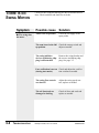
THE SPRUE
PICKER DOES
NOT CYCLE
There are several reasons the sprue picker does not cycle. You
need to check electrical connections, fuses, and the automatic
setting.
Symptom
Possible cause
Solution
◆ The sprue pick-
Electrical connections
are not correct.
Check that:
er does not cycle.
❒ The sprue picker is
plugged into a power
source.
❒ The main power source is
on.
❒ The interface cables are
connected.
❒ The fuses are good.
❒ The power to the press is
on.
◆ Automatic oper-
The press is not in auto.
Check that the interface wiring
is properly connected.
The sprue picker is not in
Home position.
Return the sprue picker to
Home using the manual button
on the hand control.
ation is not available.
6-4
TROUBLESHOOTING
MX Sprue Picker, PC-E IV Control
UGR002/1099
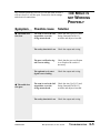
The common problems you will see with the mold are that it
will not close or it will not open. You need to check settings
and electrical connections.
THE MOLD IS
NOT WORKING
PROPERLY
Symptom
Possible cause
Solution
◆ The mold does
The arm is not in the full
up position, or at the
swing outward end.
Check the Arm Up (LS-3) and
Swing Outward End (LS-1)
switches and adjust as needed.
not close.
The safety interlock is on. Check the output and wiring.
◆ The mold does
not open.
The part verification signal is not working.
Check that the part verification
is on. Replace the switch if
necessary.
The optional cycle start
signal is not working.
Check the output and wiring.
The arm is not in the full
up position, or at the
swing outward end.
Check the Arm Up (LS-3) and
Swing Outward End (LS-1)
switches and adjust as needed.
The safety interlock is on. Check the output and wiring.
UGR002/1099
MX Sprue Picker, PC-E IV Control
TROUBLESHOOTING
6-5
THE ARM IS
NOT WORKING
PROPERLY
The problems you will see with the arm is that it will not
extend or retract properly. Check electrical wiring, switches,
valves, and air lines.
Symptom
Possible cause
Solution
◆ There is no arm
extension (no arm
down).
There is no air pressure.
Check air supply to the sprue
picker. Check for leaks.
The mold is not fully
open.
Check that the interface wiring
is correct.
The sprue picker is not
swung fully in or fully
out.
Check the LS-1 and LS-2
switches and adjust as necessary.
Vertical stroke adjustment block is set too low.
Loosen stroke adjustment
block and set higher to correct
stroke.
The arm down flow control is shut off.
Adjust the down speed control;
replace as needed.
The main arm solenoid
valve is not functioning.
Replace the main arm solenoid
valve.
The air lines/seals are
damaged or leaking.
◆ There is no arm
retraction (no arm
up).
6-6
TROUBLESHOOTING
Check air lines and seals;
replace as needed.
There is no air pressure.
Check air supply to the sprue
picker.
The up solenoid is not
functioning.
Replace the up solenoid valve.
MX Sprue Picker, PC-E IV Control
UGR002/1099
When the strip is not working properly, it does not move forward or backward. You need to adjust the strip speed control,
replace the valve, or check the air lines.
STRIP MOTION
IS NOT
WORKING
Symptom
Possible cause Solution
◆ There is no strip
forward motion.
There is no air pressure.
Check air supply to the sprue
picker. Check for leaks.
Strip stroke adjustment
set too short.
Check strip stroke adjustment
for proper distance.
The strip forward speed
control is shut off.
Adjust the strip forward speed
control; replace as needed.
The strip valve is not
functioning.
Check the strip valve and
replace as needed.
The air lines/seals are
damaged or leaking.
Check air lines and seals and
replace as needed.
There is no air pressure.
Check air supply to the sprue
picker. Check for leaks.
Strip stroke adjustment
set too short.
Check strip stroke adjustment
for proper distance.
◆ There is not strip
backward motion.
Adjust the strip backward
The strip backward speed speed control; replace as needcontrol is shut off.
ed.
UGR002/1099
The strip valve is not
functioning.
Check the strip valve and
replace as needed.
The air lines/seals are
damaged or leaking.
Check air lines and seals and
replace as needed.
MX Sprue Picker, PC-E IV Control
TROUBLESHOOTING
6-7
THERE IS NO
SWING MOTION
Causes for the swing not moving are due to switches and air
lines. Check switches and check for air leaks.
Symptom
Possible cause
Solution
◆ The swing does
There is no air pressure.
Check the air supply to the
sprue picker.
The arm is not in the full
up position.
Check the arm up switch and
adjust as needed.
The swing inhibitor
devices used during shipping is still attached.
Remove the swing bracket and
the screws used during shipping. See page 3-5.
not move.
Part verification is not on Check and adjust the verification switches as needed.
(during Auto mode).
6-8
TROUBLESHOOTING
The swing flow controls
are shut off.
Adjust the swing speed control; replace as needed.
The air lines/seals are
damaged or leaking.
Check air lines and seals and
replace as needed.
MX Sprue Picker, PC-E IV Control
UGR002/1099
When the gripper does not grab the sprue, check the solenoid,
switches, and the air lines.
THE GRIPPER
DOES NOT
WORK
Symptom
Possible cause
Solution
◆ The gripper does
There is no air pressure.
Check the air supply; adjust as
needed.
not work.
The arm is not in mold or Extend the arm in the mold or
extended over gate (durover gate area.
ing Manual mode).
UGR002/1099
The grip solenoid is not
working properly.
Replace the grip solenoid.
The air lines/seals are
damaged or leaking.
Check air lines and seals and
replace as needed.
The part/sprue is sticking
to the mold.
Adjust the ejector stroke.
Correct the mold problem.
Main grip is not selected
in Program mode.
Place grip on in Program
mode.
Gripper is faulty.
Check gripper for broken
spring or cracked housing.
Replace as needed.
MX Sprue Picker, PC-E IV Control
TROUBLESHOOTING
6-9
THERE IS
VACUUM
NO
When the vacuum is not working, check settings, air line
problems, and bad solenoids.
Symptom
Possible cause Solution
◆ There is no vac-
The air pressure is incor- Check the air pressure. Adjust
rect.
as needed.
uum.
The mode setting is incor- Set the mode for vacuum.
rect.
The vacuum solenoid is
not working properly.
Replace the vacuum solenoid.
The air lines/seals are
damaged or leaking.
Check the air lines and seals
and replace as needed.
The part/sprue is sticking Adjust the ejector stroke.
to the mold.
Correct the mold problem.
6-10
TROUBLESHOOTING
MX Sprue Picker, PC-E IV Control
UGR002/1099
Conair has made the largest investment in customer support in
the plastics industry. Our service experts are available to help
with any problem you might have installing and operating
your equipment. Your Conair sales representative also can help
analyze the nature of your problem, assuring that it did not
result from misapplication or improper use.
To contact Customer Service personnel, call:
From outside the United States, call: 814-437-6861
WE’RE HERE
TO HELP
HOW TO
CONTACT
CUSTOMER
SERVICE
You can commission Conair service personnel to provide onsite service by contacting the Customer Service Department.
Standard rates include an on-site hourly rate, with a one-day
minimum plus expenses.
If you do have a problem, please complete the
following checklist before calling Conair:
❒ Make sure you have all model, serial and parts list numbers
for your particular equipment. Service personnel will need
this information to assist you.
BEFORE YOU
CALL ...
❒ Make sure power is supplied to the equipment.
❒ Make sure that all connectors and wires within and between
the sprue picker and related components have been
installed correctly.
❒ Check the troubleshooting guide of this manual for a solution.
❒ Thoroughly examine the instruction manual(s) for associated equipment, especially controls. Each manual may have
its own troubleshooting guide to help you.
❒ Check that the equipment has been operated as described in
this manual.
❒ Check accompanying schematic drawings for information
on special considerations.
UGR002/1099
CUSTOMER SERVICE
Additional manuals and
prints for your Conair
equipment may be
ordered through the
Customer Service or
Parts Departments for
a nominal fee.
APPENDIX A-1
EQUIPMENT
GUARANTEE
Conair guarantees the machinery and equipment on this
order, for a period as defined in the quotation from date of
shipment, against defects in material and workmanship
under the normal use and service for which it was recommended (except for parts that are typically replaced after
normal usage, such as filters, liner plates, etc.). Conair’s
guarantee is limited to repairing or replacing, at our
option, the part or parts determined by us to be defective
after examination. The customer assumes the cost of transportation of the part or parts to and from the factory.
PERFORMANCE
WARRANTY
Conair warrants that this equipment will perform at or
above the ratings stated in specific quotations covering the
equipment or as detailed in engineering specifications,
provided the equipment is applied, installed, operated and
maintained in the recommended manner as outlined in our
quotation or specifications.
Should performance not meet warranted levels, Conair at
its discretion will exercise one of the following options:
● Inspect the equipment and perform alterations or
adjustments to satisfy performance claims. (Charges
for such inspections and corrections will be waived
unless failure to meet warranty is due to misapplication, improper installation, poor maintenance practices
or improper operation.)
● Replace the original equipment with other Conair
equipment that will meet original performance claims
at no extra cost to the customer.
● Refund the invoiced cost to the customer. Credit is
subject to prior notice by the customer at which time a
Return Goods Authorization Number (RGA) will be
issued by Conair’s Service Department. Returned
equipment must be well crated and in proper operating
condition, including all parts. Returns must be prepaid.
Purchaser must notify Conair in writing of any claim and
provide a customer receipt and other evidence that a claim
is being made.
WARRANTY
LIMITATIONS
A-2
APPENDIX
Except for the Equipment Guarantee and Performance
Warranty stated above, Conair disclaims all other warranties with respect to the equipment, express or
implied, arising by operation of law, course of dealing,
usage of trade or otherwise, including but not limited to
the implied warranties of merchantability and fitness for
a particular purpose.
GUARANTEE/WARRANTY
UGR002/1099
You can add a second descent slowdown circuit to an MX
model sprue picker. The two valves that are part of the second
descent slowdown circuit are the vertical valve and the swing
valve.
The second descent slowdown valve is an air actuated valve. It
is actuated by the swing motion. When the swing motion
swings out, the pressure used to swing the arm out energizes
the slowdown valve. When the arm descends in the swing out
position, the exhaust of the vertical is diverted through the
second descent slowdown valve through a metering valve.
ADDING A
SECOND
DESCENT
This metering valve creates a second slower speed.
When the arm swings back in, the pressure to the second
descent slowdown valve is no longer present and the air for
the vertical cylinder goes straight through the second descent
slowdown valve without being metered.
Warning
The air supply to the sprue picker must be disconnected and drained from the machine before
doing any installation or maintenance. Failure to
heed this warning may result in personal injury.
UGR002/1099
MX Sprue Picker, PC-E IV Control
APPENDIX
A-3
ADDING A
SECOND
DESCENT:
PREPARATION
To add a second descent slowdown circuit to and MX sprue
picker:
1
2
Shut off the air supply to the sprue picker.
3
4
Apply thread sealer to all unsealed threads.
Disconnect the air supply to the sprue picker.
Cut the tubing and attach.
Cut
Tubing Length, in. Location
MX60 to MX150
8mm
5
8mm
5
8mm
11.25
4mm
11.5
6mm
--MX250 to MX550
8mm
5
8mm
5
8mm
11.25
6mm
11.5
8mm
--MX350T to MX550T
8mm
5
8mm
5
8mm
11.25
6mm
11.5
8mm
---
11.5 inch long
tubing to
Swing Arm
5 inch long
tubing to
Port A
Slowdown valve to Flow Control valve
Flow Control valve to Quick Exhaust valve
Slowdown valve to Quick Exhaust valve
Slowdown valve to Swing Arm
Slowdown valve to Main cylinder
Slowdown valve to Flow Control valve
Flow Control valve to Quick Exhaust valve
Slowdown valve to Quick Exhaust valve
Slowdown valve to Swing Arm
Slowdown valve to Main cylinder
Slowdown valve to Flow Control valve
Flow Control valve to Quick Exhaust valve
Slowdown valve to Quick Exhaust valve
Slowdown valve to Swing Arm
Slowdown valve to Main cylinder
Flow Control valve
5 inch long
tubing
Quick Exhaust
valve
To Main
Cylinder
Slowdown
valve
A-4
APPENDIX
MX Sprue Picker, PC-E IV Control
11.25 inch tubing from
main cylinder valve to
pressure port B
UGR002/1099
1
Mark the template on the junction box cover.
Remove the junction box cover and, using the template
that comes with the second descent, mark the template on
the junction box.
Junction box cover
ADDING A
SECOND
DESCENT:
ATTACHING
1.750 in (44mm)
0.136 in (3.5mm)
drill through, 2 places
1.250 in (32mm)
1.181 in (33mm)
2
3
Drill the holes.
Mount the valve to the junction box
below the valve assembly (see picture) using the mounting screws.
Mark template in this
area and mount here.
4
Junction box
Replace the cover.
UGR002/1099
MX Sprue Picker, PC-E IV Control
APPENDIX
A-5
ADDING A
SECOND
DESCENT:
CONNECTING
QUICK EXHAUST
1 Disconnect the tubing from the main vertical
arm at the manifold connection.
2 Connect this hose to the pressure port on the
slowdown valve.
3 Remove flow control and fitting from main
cylinder valve on the manifold at port B.
4 Remove Y fitting from quick exhaust valve,
supplied with kit; apply thread sealer.
5 Thread quick exhaust valve into main cylinder
at port B. Be careful to not overtighten. Align port as
shown.
6 Reconnect Y fitting to quick-exhaust valve
and reconnect air lines to Y fitting.
Attach Quick
Exhaust valve here
Align port in this
orientation
Main cylinder
port B
Tubing from main vertical arm connected to
the pressure port of
the slowdown valve
A-6
APPENDIX
MX Sprue Picker, PC-E IV Control
UGR002/1099
1 Locate Swing valve port A.
2 Cut tubing about 4 inches (102mm) from the
fitting.
3 Insert Y fitting.
4 Connect air line from top of slowdown valve
into Y fitting.
ADDING A
SECOND
DESCENT:
CONNECTING
SWING VALVE
Air line to Swing valve
UGR002/1099
MX Sprue Picker, PC-E IV Control
APPENDIX
A-7
ADDING A
SECOND
DESCENT:
ADJUSTMENTS
To adjust the speed of the second descent slowdown valve:
1
Turn Knob A (overall speed)
Turn Knob A clockwise to slow the speed of the arm and
counterclockwise to increase the speed of the arm.
2
Turn Knob B (second descent speed)
To adjust the speed of the arm for second descent, turn
Knob B clockwise to slow second descent speed and
counterclockwise to increase second descent.
Knob A
Knob B
A-8
APPENDIX
MX Sprue Picker, PC-E IV Control
UGR002/1099
System Configuration
PC-E IV Control
UGR002/1099
MX Sprue Picker, PC-E IV Control
ELECTRICAL
DIAGRAMS
APPENDIX
A-9
ELECTRICAL
DIAGRAMS
Sprue Picker and IMM Interface
PC-E IV Control
CAUTION: Equipment hazard.
Do not plug an MX Sprue Picker with a PC-E III
Control into an interface wired for a PC-E IV
Control SPI interface.
Do not plug an MX Sprue Picker with a PC-E IV
Control into an interface wired for a PC-E III
Control interface.
Damage will occur! Call Conair Service if you
are unsure or have any questions.
A-10
APPENDIX
MX Sprue Picker, PC-E IV Control
UGR002/0100
Solenoid and Limit Switch Wiring
PC-E IV Control
UGR002/1099
MX Sprue Picker, PC-E IV Control
ELECTRICAL
DIAGRAMS
APPENDIX
A-11
ELECTRICAL
DIAGRAMS
Relay and IMM Interface
PC-E IV Control
CAUTION: Equipment hazard.
Do not plug an MX Sprue Picker with a PC-E III
Control into an interface wired for a PC-E IV
Control SPI interface.
Do not plug an MX Sprue Picker with a PC-E IV
Control into an interface wired for a PC-E III
Control interface.
Damage will occur! Call Conair Service if you
are unsure or have any questions.
A-12
APPENDIX
MX Sprue Picker, PC-E IV Control
UGR002/0100
The motion sequence is the movement pattern that the arm
travels.
Motion
Sequence LCD Displays
P01 MUX
P01 MUX
FIXED/MOV.: MOVABLE
U/L MOTION: U
SWING W/WO: W
P02 FUX
P02 FUX
FIXED/MOV: FIXED
U/L MOTION: U
SWING W/WO: W
P03 MLX
P03 MLX
FIXED/MOV.: MOVABLE
U/L MOTION: L
SWING W/WO: W
UGR002/1099
MOTION
SEQUENCES
Movement Steps:
1.
2.
3.
4.
5.
6.
7.
8.
9.
10.
Arm extend movable mold side
Grip part/sprue
Strip
Arm retract
Swing outward
Arm second extend
Release part/sprue
Arm second retract
Swing inward
Strip to home position
1.
2.
3.
4.
5.
6.
7.
8.
9.
10.
Arm extend fixed mold side
Grip part/sprue
Strip
Arm retract
Strip back
Swing outward
Arm second extend
Release part/sprue
Arm second retract
Swing inward
1.
2.
3.
4.
5.
6.
7.
8.
9.
10.
Arm extend movable mold side
Strip (approach)
Grip part/sprue
Strip back
Arm retract
Swing outward
Arm second extend
Release sprue/part
Arm second retract
Swing inward
MX Sprue Picker, PC-E IV Control
APPENDIX
A-13
MOTION
SEQUENCES
Motion
Sequence LCD Displays
P04 FLX
P04 FLUX
FIXED/MOV.: FIXED
U/L MOTION: L
SWING W/WO: W
A-14
APPENDIX
P05 MLB
P05 MLB
FIXED/MOV: MOVABLE
U/L MOTION: L
SWING W/WO: WO
P06 FLB
P06 FLB
FIXED/MOV.: FIXED
U/L MOTION: L
SWING W/WO: WO
MX Sprue Picker, PC-E IV Control
Movement Steps:
1.
2.
3.
4.
5.
6.
7.
8.
9.
10.
Arm extend fixed mold side
Strip (approach)
Grip part/sprue
Strip back
Arm retract
Swing outward
Arm second extend
Release part/sprue
Arm second retract
Swing inward
1.
2.
3.
4.
5.
6.
Arm extend movable mold side
Strip (approach)
Grip part/sprue
Strip back
Release part/sprue
Arm retract
1.
2.
3.
4.
5.
5.
Arm extend fixed mold side
Strip (approach)
Grip part/sprue
Strip back
Release sprue/part
Arm retract
UGR002/1099
MOTION
SEQUENCES
Motion
Sequence LCD Displays
P07 MUB
P07 MUB
FIXED/MOV.: MOVABLE
U/L MOTION: U
SWING W/WO: WO
P08 FUB
P08 FUB
FIXED/MOV: FIXED
U/L MOTION: U
SWING W/WO: WO
P09 FLK
P09 FLK
FIXED/MOV.: FIXED
U/L MOTION:
L+SWING
SWING W/WO: PART
FIRST
UGR002/1099
Movement Steps:
1.
2.
3.
4.
5.
6.
7.
8.
9.
10.
Arm extend movable mold side
Grip part/sprue
Strip
Arm retract
Swing outward
Arm second extend
Release part/sprue
Arm second retract
Swing inward
Strip to home position
1.
2.
3.
4.
5.
6.
7.
8.
9.
10.
Arm extend fixed mold side
Grip part/sprue
Strip
Arm retract
Strip back
Swing outward
Arm second extend
Release part/sprue
Arm second retract
Swing inward
1.
2.
3.
4.
5.
6.
7.
8.
9.
10.
Arm extend movable mold side
Strip (approach)
Grip part/sprue
Strip back
Arm retract
Swing outward
Arm second extend
Release sprue/part
Arm second retract
Swing inward
MX Sprue Picker, PC-E IV Control
APPENDIX
A-15
MOTION
SEQUENCES
Motion
Sequence LCD Displays
P10 FLR
P10 FLR
FIXED/MOV.: FIXED
U/L MOTION: L+
SWING
SWING W/WO:
SPRUE 1ST
1.
2.
3.
4.
5.
6.
7.
8.
9.
10.
Arm extend fixed mold side
Strip (approach)
Grip part/sprue
Strip back
Arm retract
Swing outward
Arm second extend
Release part/sprue
Arm second retract
Swing inward
P11 FL3
P11 FL3
FIXED/MOV: FIXED
U/L MOTION: L +
SWING
OPT DESCNT: 3RD
1.
2.
3.
4.
5.
6.
Arm extend movable mold
side
Strip (approach)
Grip part/sprue
Strip back
Release part/sprue
Arm retract
1.
2.
3.
4.
5.
5.
Arm extend fixed mold side
Strip (approach)
Grip part/sprue
Strip back
Release sprue/part
Arm retract
P012 FLC
APPENDIX A-16
Movement Steps:
P12 FLC
FIXED/MOV.: FIXED
U/L MOTION: L +
SWING
OPT CUT: NIPPER
MX Sprue Picker, PC-E IV Control
UGR002/1099
MOTION
SEQUENCES
Motion
Sequence LCD Displays
P13 FLW
P13 FLW
FIXED/MOV.: FIXED
U/L MOTION: L +
SWING
OPT POSIT: OUTWARD
P14 LXB
P14 LXB
FIXED/MOV: FIXED
U/L MOTION: L +
SWING
SPRU RELS:
INMOLD
UGR002/1099
Movement Steps:
1.
2.
3.
4.
5.
6.
7.
8.
9.
10.
Arm extend movable mold side
Grip part/sprue
Strip
Arm retract
Swing outward
Arm second extend
Release part/sprue
Arm second retract
Swing inward
Strip to home position
1.
2.
3.
4.
5.
6.
7.
8.
9.
10.
Arm extend fixed mold side
Grip part/sprue
Strip
Arm retract
Strip back
Swing outward
Arm second extend
Release part/sprue
Arm second retract
Swing inward
MX Sprue Picker, PC-E IV Control
APPENDIX A-17