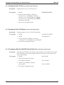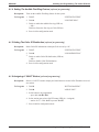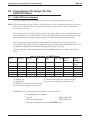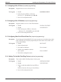
1
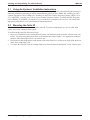
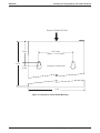
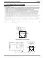
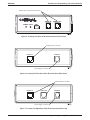
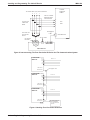
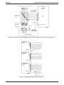
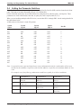
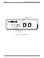
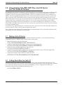
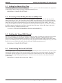
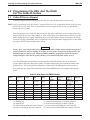
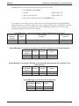
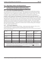
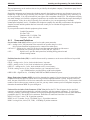
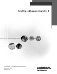
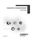
R Installing and Programming the Caller ID Feature 1.0 Introducing the Caller ID Feature The caller ID feature supports an externally connected, customer-supplied caller ID device illustrated in Figure 1. Depending on the model you have, this hardware device supports either four or eight caller ID conditioned lines per unit. You can serially connect four- and eight-port devices to give larger systems the ability to support a maximum of 68 caller ID conditioned lines. The number of caller ID conditioned lines that can be used on a smaller system such as the DSU/DSU II depend on the system’s line capacity (usually 24 lines with expansion added). The caller ID unit interfaces with the common equipment cabinet through any undedicated serial data port. Any proprietary LCD speakerphone can receive and display caller ID information. The display conveys all available caller ID information from the time the call rings at the station, through all line transitions, until the line disconnects. The communications system stores caller ID information in its SMDA storage and makes it available in the SMDA printout. 2.0 Installing The Caller ID Device Installation Notice The Underwriters Laboratories regulation 1459, 2nd edition, requires that you be made aware of the following precautions when installing a telephone that is to be directly connected to the telephone company network: 1. Never install telephone wiring during a lightning storm. 2. Never install telephone jacks in wet locations unless the jack is specifically designed for wet locations. 3. Never touch uninsulated telephone wires or terminals unless the telephone line has been disconnected at the network interface. 4. Use caution when installing or modifying telephone lines. SERIAL IN POWER DATA SERIAL OUT SW1 Figure 1. Caller ID Device This manual has been developed by Comdial Corporation (the “Company”) and is intended for the use of its customers and service personnel. The information in this manual is subject to change without notice. While every effort has been made to eliminate errors, the Company disclaims liability for any difficulties arising from the interpretation of the information contained herein. The information contained herein does not purport to cover all details or variations in equipment or to provide for every possible contingency to be met in connection with installation, operation, or maintenance. Should further information be desired, or should particular problems arise which are not covered sufficiently for the purchaser’s purposes, contact Comdial, Inside Sales Department, Charlottesville, Virginia 22906. Printed in U.S.A. IMI89–320.01 10/98 Installing and Programming The Caller ID Device 2.1 IMI89-320 Using the Systems’ Installation Instructions Install the caller ID device with the communications system. If necessary, refer to the following publications for additional information depending on which communications system you have: IMI66–001, Installing the DXP Common Equipment Cabinet; IMI66–105, Installing the DXP Plus Common Equipment Cabinet; IMI66-134 or FX_CABNT.PDF, Installing the FX Series System Commn Equipment Cabinet. For DSU and DSU II systems, refer to IMI66-107 and IMI66-132 respectively, System Hardware and Software Instructions. You can find the appropriate publication in your system hardware instructions binder. 2.2 Mounting the Caller ID You can either surface-mount or wall-mount the caller ID. To surface-mount the device, set it on a flat, solid surface close to the communications system. To wall-mount the caller ID, follow these steps: 1. Insert two #10 panhead screws (obtained locally) in the wall until their heads are within 1/8-inch of the wall surface. Use the spacing dimensions shown in the template provided in Figure 2. Use appropriate anchoring hardware when mounting the device on a hollow wall. 2. Position the keyhole-shaped holes in the bottom of the caller ID device over the screw heads. Slide the device down until a slight click is felt. 3. To remove the caller ID, lift it up to unsnap both screws from the bottom, and then lift it away from the wall. 2 − Installing And Programming The Caller ID Device IMI89-320 Installing and Programming The Caller ID Device Front of Caller ID Unit 2.800 3.820 inches (approx. 3 13/16 inches) 9.500 Template For Wall Mount 0.400 6.330 Figure 2. Template For Caller ID Wall Mounting Installing And Programming The Caller ID Device − 3 Installing and Programming The Caller ID Device 2.3 IMI89-320 Connecting the Caller ID to the System See Figures 8 and 10 for the interconnection diagrams. Figures 9 and 11 illustrate the method for interconnecting multiple caller ID units. 1. Connect the line port modular jacks on the caller ID device to the CO line connections using the kit-supplied cable. See Figure 3 for connection details and Figures 6 and 7 for the modular jack locations on the caller ID. Also, connect these CO lines to the communications system’s common equipment cabinet. 2. Connect the caller ID device’s serial data out connector (labeled RS232 Out) to a serial data port on the common equipment cabinet of the communications system. See Figure 5. Use the kit-supplied 6-conductor modular line cord for this connection. Use a serial data port on the common equipment as follows: DXP system, use either the RS-232 port 1, port 2 or any undedicated serial data port provided by an installed communications card; DXP Plus system, use any undedicated serial data port provided by an installed communications card; FX Series system, use any serial data port labeled COM3 - COM 10; DSU system, use Data Port B; DSU II system, use COM2; Unisyn sytem, use Data Port B. See Figure 3 for the connection details. 3. Connect the caller ID device’s power supply to an 120 VAC electrical outlet, and connect the power supply’s output cable to the power connector on the rear of the caller ID device illustrated in Figure 7. Verify the POWER LED is constant ON. 4. Set the parameter switches SW1 (see section 2.4). 5. Verify operation by observing the DATA LED. This LED should light during an incoming call on a caller ID enabled line, usually after the first ring burst. Line 4 Line 3 Line 2 Line 1 2 4 8 1 7 3 6 5 RJ-45 Figure 3. Detailing The Line Connections Modular Jack Pin 1 Pin 2 Pin 3 Pin 4 Pin 5 Pin 6 Serial Out Jack Serial In Jack N/C SG N/C TD (out) RTS (out) CTS (in) RTS (out) CTS (in) RD (in) N/C SG N/C Connect To Serial Data Port On Common Equipment Cabinet Using Kit-Supplied 6-Conductor Line Cord RJ-11 3 2 1 6 5 Modular Jack (Front View) Figure 4. Detailing The Serial Data Connections 4 − Installing And Programming The Caller ID Device 4 IMI89-320 Installing and Programming The Caller ID Device Modular RJ-11 Serial Data Connectors SERIAL IN POWER DATA SERIAL OUT SW1 Figure 5. Locating The Caller ID Serial Connections (Front View) Modular RJ-45 Line Jack PORTS 1-4 POWER IN Power Supply Connector Figure 6. Locating The Four-Port Caller ID Connections (Rear View) Modular RJ-45 Line Jacks PORTS 1-4 PORTS 5-8 POWER IN Power Supply Connector Figure 7. Locating The Eight-Port Caller ID Connections (Rear View) Installing And Programming The Caller ID Device − 5 Installing and Programming The Caller ID Device IMI89-320 Common Equipment Cabinet To Central Office (CO) Line Connections 4 3 2 1 Lines to Common Equipment From CO Connection 4 Typical Cross Connection Block Line Ports 3 2 1 Kit-Supplied Cable Lines from CO To Caller ID Device Serial Data Port To AC Outlet See Figure 3 for detail Line LinePorts Ports 1-4 1-4 PWR Caller ID Caller IDDevice Device Figure 8. Interconnecting The Four-Port Caller ID Device And The Communications System CALLER ID DEVICE P O R T S RS-232 In RS-232 Out CALLER ID DEVICE P O R T S Lines 9-12 Kit-Supplied Cable Lines 5-8 RS-232 In RS-232 Out CALLER ID DEVICE P O R T S RS-232 In RS-232 Out Lines 1-4 Comm Equipment Serial Data Port or Next Caller ID Device Figure 9. Stacking Four-Port Caller ID Devices 6 − Installing And Programming The Caller ID Device IMI89-320 Installing and Programming The Caller ID Device To Central Office (CO) Line Connections Common Equipment Cabinet 876 54 321 Lines to Common Equipment From CO Connection 8 7 6 5 4 3 2 1 Typical Cross Connection Block Kit-Supplied Cable Lines from CO To Caller ID Device Line Ports Serial Data Port To AC Outlet See Figure 3 for detail 5-8 1-4 5-8 1-4 LinePorts Ports Line PWR Caller ID Device Figure 10. Interconnecting The Eight-Port Caller ID Device And The Communications System CALLER ID DEVICE P O R T S RS-232 In RS-232 Out CALLER ID DEVICE P O R T S Lines 17-24 Kit-Supplied Cable Lines 9-16 RS-232 In RS-232 Out CALLER ID DEVICE P O R T S RS-232 In RS-232 Out Lines 1-8 Comm Equipment Serial Data Port or Next Caller ID Device Figure 11. Stacking Eight-Port Caller ID Devices Installing And Programming The Caller ID Device − 7 Installing and Programming The Caller ID Device 2.4 IMI89-320 Setting the Parameter Switches The caller ID device has one bank of parameter-controlling Dual In-Line Pin (DIP) switches located on its front panel. This bank of switches illustrated in Figure 12 is labeled SW1. On this Caller ID model, there are no DIP switches for setting baud rate, data bits, parity, and stop bits. These parameters are fixed at 9600 baud, 8 data bits, no parity bits, and 1 stop bit (9600, 8, N, 1). When you are installing multiple caller ID devices, set switches SW1-1 through SW1-4 to the settings detailed in the chart shown below. A DIP switch is ON when it is in the UP position. Switch SW1-1 OFF ON OFF ON OFF ON OFF ON OFF ON OFF ON OFF ON OFF ON Switch SW1-2 OFF OFF ON ON OFF OFF ON ON OFF OFF ON ON OFF OFF ON ON Switch SW1-3 OFF OFF OFF OFF ON ON ON ON OFF OFF OFF OFF ON ON ON ON Switch SW1-4 OFF OFF OFF OFF OFF OFF OFF OFF ON ON ON ON ON ON ON ON Box ID 1 2 3 4 5 6 7 8 9 10 11 12 13 14 15 16 Note: It is possible to mix 4-port and 8-port boxes in any combination desired for a total number of lines up to 68 if the last box added is a 8-port box. If the last box added is a 4-port box, the maximum number of lines is 64. For example, any of the following combinations would be acceptable for a 16-line installation: Box ID Combination 1 Combination 2 Combination 3 1 8-port box lines 1-8 8-port box Lines 9-16 8-port box lines 1-8 4-port box lines 9-12 4-port box lines 13-16 4-port box lines 1-4 4-port box lines 5-8 4-port box lines 9-12 4-port box lines 13-16 2 3 4 8 − Installing And Programming The Caller ID Device IMI89-320 Installing and Programming The Caller ID Device DIP Switch (Switches 1-4) (UP position = ON) SERIAL IN POWER DATA SERIAL OUT SW1 Data LED Power LED Figure 12. Locating The DIP Switches Installing And Programming The Caller ID Device − 9 Installing and Programming The Caller ID Device IMI89-320 3.0 Programming The DXP, DXP Plus, And FX Series For The Caller ID Feature In programming the common equipment for caller ID support, you must match the data baud rate with that of the caller ID device (9600, 8, N, 1), you must enable the caller ID lines, and you must assign them to ring on the telephones. Calls will ring on the assigned telephones as well as on telephones to which a call is transferred. In addition, caller ID programming options allow you to set the absorb ring time (amount of time the system waits while it generates caller ID information before it generates system ringing); enable the deleting of the viewed RNA records when viewed by any user; and enter the local area codes and local exchange codes that you want the system to skip when it automatically dials a return call. You can also assign caller ID ring no-answer (RNA) capability to the telephones that are on caller ID lines. Users of these telephones have the ability to review this caller ID RNA information and return the call. They can also note if anyone else has already viewed a record thus preventing redundant returns. A station user may automatically retrieve and dial the last, first, or any in between Caller ID number displayed at his or her station by using a “SAVE” button assigned to the station. Also, a station user may transfer calls to another station causing that station to ring. If the other station has caller ID capability, the caller information will also transfer. 3.1 Making Caller ID Active When caller identification (ID) information is available from the central office, you must take the following programming actions in VMMI to make Caller ID active in the system: 1. Match the line ports to the caller ID feature. LINESLINE PROGRAMMINGLINE TYPE SPECIFIC. . . 2. Assign the caller ID lines to the stations as delayed or directed ringing lines. STATIONSSTATION PROGRAMMINGRINGING ASSIGNMENTS. . . 3. Enable line answer and line originate in a class of service. STATIONSCLASS OF SERVICEPAGE 5. . . 4. Assign the line answer and line originate class of service to the stations (as day COS and/or night COS). STATIONSSTATION PROGRAMMINGGENERAL. . . 5. Assign special-purpose station buttons to control the feature. STATIONSSTATION PROGRAMMINGBUTTON MAPPING. . . 3.2 Setting Baud Rate For Caller ID You must program the parameters of the serial data port where you have connected the caller ID device. The serial data port parameters must match the data parameters of the caller ID device which are 9600 baud, eight data bits, no parity bit, and one stop bit. Flow control or handshaking is “None.” Program the serial data port parameters from the following VMMI programming screen: SYSTEMSERIAL PORTS. . . 10 − Installing And Programming The Caller ID Device IMI89-320 3.3 Installing and Programming The Caller ID Device Setting the Absorb Ring Time You must specify the amount of time the system waits while it generates caller ID information before it generates system ringing. Do this from the following VMMI programming screen: PERIPHERALSCALLER IDOPTIONS. . . 3.4 Reviewing Caller ID Ring No-Answer (RNA) Calls This feature offers telephone users the ability to use their telephone’s display to review calls that ring at their stations while they are away. The system stores caller ID RNA records and allows users to review them and use one-button dialing to return those calls that need returning. The feature also displays the identification of the last station that reviewed the records thus helping to prevent multiple call backs to the same number. After users review the caller ID RNA records, the system deletes the records from their telephones yet retains the records in the SMDA storage so that the users can look at the records later if they must. Activate this feature with action taken on the following VMMI programming screen: STATIONSSTATION PROGRAMMINGRINGING ASSIGNMENTS |. . . 3.5 Deleting the Viewed RNA Record When the system makes caller ID RNA information available to a group of stations, any station user in the group can review the information by pressing the telephone’s CID button. When he or she does this, the system removes the record from that telephone but continues to flash the CID button status light for other stations in the group. If you enable this feature, the system will remove the caller ID record from all telephones if any user in the group views a record. Enable this feature from the following VMMI programming screen: PERIPHERALSCALLER IDOPTIONS. . . 3.6 Constructing The Local Call Table When telephone users review caller ID RNA calls, they press their SAVE button to return the call, and the system automatically dials the number. If the area code or office code part of the stored number matches the entries that you program with this procedure, the system will skip that part of the number as it dials. Take programming action on the following VMMI programming screen to choose those area and office codes that you want the system to skip: PERIPHERALSCALLER IDLOCAL CALL TABLE. . . Installing And Programming The Caller ID Device − 11 Installing and Programming The Caller ID Device IMI89-320 4.0 Programming The DSU, And The DSUII For The Caller ID Feature 4.1 Caller ID Service Support You must program lines and stations for Caller ID service per the instructions in this section. NOTE: When programming using the telephone, a lighted LED next to the programming button for the selection indicates the current status. When a single button provides a toggle (on/off) action, the lighted LED indicates the active feature. Since the station receives Caller ID data between the first and second rings, you can arrange for the first ring on Caller ID lines to be either audible or silent. Selecting the silent option ensures that the Caller ID data is displayed prior to ringing, eliminating the loss of Caller ID data because of premature answering. A station user may automatically retrieve and dial the last Caller ID number displayed at his or her station by using a “SAVE” button assigned to the station. CAUTION Seven-, eight-, and 11-digit numbers are always dialable while 10-digit numbers must be transformed by the system before they are dialable. To arrange for the system to transform a 10-digit number into dialable format, you must use the VDT programming method to program the local area code and 6-digit area/office codes into the system’s memory. You cannot do this from station 10 or 12. All Caller ID features require that the customer-supplied Caller ID interface deliver its data to the system’s RS232 data port, data port B/COM2. You must configure this port to match the output of the decoder device. The recommended configuration is 9600 baud, with eight data bits and one stop bit. The system provides Caller ID information as part of the SMDR printout. An example of this appears below. Call # Station # Line # 1 1000 12 2 3 4 5 6 7 8 12 3 1 1 4 4 1(D) 1(D) 10 10 10 10 Caller ID Information On SMDR Printout Date Time Call Answer length Time 10/15/92 04:38 0.1 10/15/92 10/15/92 10/15/92 10/15/92 10/15/92 10/15/92 10/15/92 00:56 00:56 00:56 01:00 01:00 04:23 04:19 (1) outgoing call (2) outgoing call (3) unanswered incoming call, with Caller ID (4) answered incoming call, with Caller ID 0.2 NOANS 0.1 NOANS 0.1 0.2 0.2 .2 .1 .2 .0 .1 .1 Called or Call Cost Calling # 123456789 $ 0.51 0123456 5551212 /5551234 /5551234 /5556789 $ 0.00 $ 0.00 (5) unanswered incoming call, without Caller ID (6) answered incoming call, without Caller ID (7) answered incoming DISD call, with Caller ID (8) unanswered incoming DISD call, without Caller ID 12 − Installing And Programming The Caller ID Device IMI89-320 Installing and Programming The Caller ID Device If SMDR printout is not already turned on (default), turn it on as follows: 1. Press ITCM and dial ✳#746✳. 2. Dial 772. “SMDR PRINT XXX” 3. Dial 1 to enable printout. “SMDR PRINT ON” 4. Dial ✳✳ for configuration mode or SPEAKER to quit. As an option, you can arrange for the system to provide Caller ID data distribution through the RS232 data port B/COM 2 to a personal computer (PC) just as it supplies SMDA data to a data printer. This data consists of four special-purpose messages and is in the ASCII format suitable for use with PC-based application programs. The messages are as follows: Typical Message 1—sent out as soon as Caller ID data arrives from the CO Message ID and Line No. Caller ID Data End of Message Identifier (2 bytes) (15 bytes) (2 bytes) (3 bytes) 3E 3C 31 30 35 31 2D 38 30 34 2D 39 37 38 2D 32 32 30 30 20 0D 0A > < 1 0 1 1 — 8 0 4 — 9 7 8 — 2 2 0 0 CR LF Typical Message 2—sent when a ringing line with CID is answered or retrieved from hold. Message ID Line No. Station No. End of Message and Identifier (2 bytes) (2 bytes) (2 bytes) (3 bytes) 3E 3C 32 31 32 31 30 0D 0A > < 2 1 2 1 0 CR LF Typical Message 3—sent when CID data is not received from answered line or when a line is taken off-hook Message ID Line No. Station No. End of Message and Identifier (2 bytes) (2 bytes) (2 bytes) (3 bytes) 3E 3C 33 31 35 31 32 0D 0A > < 3 1 5 1 2 CR LF Typical Message 4—sent when line is made idle Message ID Line No. End of Message and Identifier (2 bytes) (2 bytes) (3 bytes) 3E 3C 34 30 35 0D 0A > < 4 0 5 CR LF Installing And Programming The Caller ID Device − 13 Installing and Programming The Caller ID Device IMI89-320 4.1.1 Assigning Caller ID Lines (required programming) Description: Programs lines to receive Caller ID service. To Program: 1. Dial 47. “CALLER ID LINES” 2. Select line ports (LED On = Selected) Line Port 1–14 = Dial 01–14 or A1–A14 Line Port 15, 16 = Dial 15, 16 or press B1, B2 Line Port 17–24 = Dial 17–24 or press HOLD and then press A1–A8. 3. Press ✳ for configuration mode. 4.1.2 Assigning Caller ID Stations (required programming) Description: Programs stations to receive Caller ID information. To Program: 1. Dial 53. 2. Dial 36. “STATION FEATURES” “CALLER ID STA.” 3. Select station ports. (LED On = Selected) —Station 10–57 = Dial 10–57 or press C10–C57. 4. Press ✳✳ for configuration mode. 4.1.3 Configuring Data Port B/COM 2 Serial Data Port (required programming) Description: If the data port B/COM 2 serial data port is not currrently set at its default values (9600 baud, 8 data bits, and 1 stop bit) program that port to have those values so that it will receive Caller ID data. To Program: 1. Dial 15. “BAUD RATE” 2. Dial 2 for data port B or COM 2. 3. Press A10 for 9600 baud. “W nD nS 9600" 4. Dial 11 or press A14 for 8 data bits and 1 stop bit. “W 8D 1S ZZZZZ” 5. Dial ✳✳ for configuration mode. 14 − Installing And Programming The Caller ID Device IMI89-320 Installing and Programming The Caller ID Device 4.1.4 Setting The Audible First Ring Feature (optional programming) Description: Turns on the Audible First Ring feature for the system. To Program: 1. Dial 17. “SYSTEM FEATURES” 2. Dial 01. “CID FIRST RING” 3. Dial 1 to enable the audible first ring (LED on) —OR— Dial 2 to silence the first ring on Caller ID lines. 4. Press ✳✳ for configuration mode. 4.1.5 Setting The Caller ID Distribution (optional programming) Description: Sends Caller ID information to data port B for access by a PC. To Program: 1. Dial 17. “SYSTEM FEATURES” 2. Dial 02. “CID DISTRIBUTION” 3. Dial 1 to enable Caller ID distribution (LED on) —OR— Dial 2 to disable Caller ID distribution. 4. Press ✳✳ for configuration mode. 4.1.6 Assigning A “SAVE” Button (optional programming) Description: Selects a “SAVE” button to display and redial the most recent Caller ID number received at a station. To Program: 1. Dial 56. “BUTTON MAPPING” 2. Dial 08. “ASSIGN SAVE” 3. Select button to be programmed —press A1–A14, B1–B10. 4. Select station ports to have SAVE button (LED On = Assigned) —station 10–57 = Dial 10–57 or press C10–C57. 5. Press ✳✳✳ for configuration mode. Installing And Programming The Caller ID Device − 15 Installing and Programming The Caller ID Device IMI89-320 5.0 Programming The Unisyn For The Caller ID Feature 5.1 Caller ID Service Support You must program lines and stations for Caller ID service per the instructions in this section. NOTE: When programming using the telephone, a lighted LED next to the programming button for the selection indicates the current status. When a single button provides a toggle (on/off) action, the lighted LED indicates the active status. Since the station receives Caller ID data between the first and second rings, you can arrange for the first ring on Caller ID lines to be either audible or silent. Selecting the silent option ensures that the Caller ID data is displayed prior to ringing, eliminating the loss of Caller ID data to premature answering. All Caller ID features require that the customer-supplied Caller ID interface deliver its data to the system’s RS232 data port B. You must configure this port to match the output of the decoder device. The recommended configuration is 9600 baud, with eight data bits and one stop bit. The system provides Caller ID information as part of the SMDR printout. An example of this appears below. Call # Station # 1 1000 2 3 4 5 6 12 10 10 Caller ID Information On SMDR Printout Line # Date Time Call length Answer Time 6 10/15/92 04:38 0.1 3 1 1 4 4 10/15/92 10/15/92 10/15/92 10/15/92 10/15/92 00:56 00:56 00:56 01:00 01:00 0.2 NOANS 0.1 NOANS 0.1 .2 .1 .2 .0 Called or Calling # 1234567890 123456 5551212 /5551234 /5551234 (1) outgoing call (5) unanswered incoming call, without Caller ID (2) outgoing call (6) answered incoming call, without Caller ID (3) unanswered incoming call, with Caller ID (4) answered incoming call, with Caller ID If SMDR printout is not already turned on (default), turn it on as follows: 1. Press ITCM and dial ✳#746✳. 2. Dial 772. “SMDR PRINT XXX” 3. Dial 1 to enable printout. “SMDR PRINT ON” 4. Dial ✳✳ for configuration mode or SPEAKER to quit. 16 − Installing And Programming The Caller ID Device IMI89-320 Installing and Programming The Caller ID Device 5.1.1 Assigning Caller ID Lines (required programming) Description: Programs lines to receive Caller ID service. To Program: 1. Dial 47. “CALLER ID LINES” 2. Select line ports (LED On = Selected) Line Port 1–6 = Dial 01–06 or press B1–B6. 3. Press ✳ for configuration mode. 5.1.2 Assigning Caller ID Stations (required programming) Description: Programs stations to receive Caller ID information. To Program: 1. Dial 53. “STATION FEATURES” 2. Dial 36. “CALLER ID STA.” 3. Select station ports. (LED On = Selected) —Station 10–25 = Dial 10–25 or press A1–A16. 4. Press ✳✳ for configuration mode. 5.1.3 Configuring Data Port B Serial Data Port (required programming) Description: If serial data port B (labeled RS232 #2) is not currrently set at its default values (9600 baud, 8 data bits, and 1 stop bit) program that port to have those values so that it will receive Caller ID data. To Program: 1. Dial 15. “BAUD RATE” 2. Dial 2 for Data Port B. 3. Press A11 for 9600 baud. “W nD nS 9600" 4. Dial 11 or press A16 for 8 data bits and 1 stop bit. “W 8D 1S ZZZZZ” 5. Dial ✳✳ for configuration mode. 5.1.4 Setting The Audible First Ring Feature (optional programming) Description: Turns on the Audible First Ring feature for the system. To Program: 1. Dial 17. “SYSTEM FEATURES” 2. Dial 01. “CID FIRST RING” 3. Dial 1 to enable the audible first ring (LED on) —OR— Dial 2 to silence the first ring on Caller ID lines. 4. Press ✳✳ for configuration mode. Installing And Programming The Caller ID Device − 17 Installing and Programming The Caller ID Device IMI89-320 6.0 Regulatory Rules And Regulations 6.1 6.1.1 Federal Communications Commission (FCC) And Industry Canada (IC) Rules And Regulations FCC Part 15 RF Emission Information This equipment contains incidental radio frequency generating circuitry and, if not installed and used properly, may cause interference to radio and television reception. This equipment has been tested and found to comply with the limits for a Class A computing device pursuant to Subpart J of Part 15 of the FCC Rules. These limits are designed to provide reasonable protection against such interference when operated in a commercial environment. Operation of this equipment in a residential area may cause interference to radio and television reception; in which case the user is encouraged to take whatever measures may be required to correct the interference. If this equipment does cause interference to radio and television reception, which can be determined by turning the equipment off and on, the user is encouraged to try to correct the interference by one or more of the following measures: reorient the television or radio receiving antenna, and/or relocate the system, the individual telephone stations, and the radio or television with respect to each other. If necessary, the user should consult the manufacturer or an experienced radio/television technician for additional suggestions. The user may find the following booklet prepared by the Federal Communications Commission helpful: “How to Identify and Resolve Radio-TV Interference Problems.” This booklet is available from the Government Printing Office, Washington, DC, 20402. Stock No. 004-000-00345-4. 6.1.2 FCC Part 68 Information This equipment complies with Part 68 of the FCC Rules. A label, located on the exterior lower left side of the cabinet, contains the FCC Registration Number(s) and Ringer Equivalence Number (REN). Notify the local telephone company when you connect the equipment to the network and provide the information shown in the following table: Line Type Service Order Code* Facilities Interface Code* Loop Start 9.0F 02LS2 Ringer Equivalence Number* Universal Service Order Code Connector RJ21X See Equipment Specification Sheet Ground Start 9.0F 02GS2 See Equipment RJ21X (See note) Specification Sheet DID Lines 9.0F–AS.2 02RV2–T Not Applicable RJ21X E&M Lines 9.0F TL11M See Equipment RJ2EX Specification Sheet T1 Line 6.0Y 04DU9–1SN Not Applicable RJ48C T1/PRI (ISDN) Line 6.0Y 04DU9–1SN Not Applicable RJ48C NOTE: State tariffs do not permit ground start operation for KF registered equipment (key system operation). Ground start operation is only permitted for MF registered equipment (KTS/PBX hybrids with both manual and pooled outgoing and incoming access to the network). The system must be configured for MF operation when using ground start operation * Refer to the paragraph titled Terms and Definitions for detailed explanations. 18 − Installing And Programming The Caller ID Device IMI89-320 Installing and Programming The Caller ID Device This equipment may not be used on coin service provided by the telephone company. Connection to party lines is subject to state tariffs. Should the equipment cause harm to the telephone network, the telephone company may disconnect your service temporarily. If possible, they will notify you in advance. If advanced notice is not practical, they will notify you as soon as possible. You will be informed of your right to file a complaint with the FCC. The telephone company may make changes in its facilities, equipment, operations or procedures that could affect the proper functioning of your equipment. If they do so, they will notify you in advance to give you an opportunity to maintain uninterrupted telephone service. In addition, the telephone company may ask that you disconnect this equipment from the network until the problem has been corrected or until you are sure that the equipment is not malfunctioning. If you experience trouble with this equipment, please contact: Comdial Corporation P.O. Box 7266 Charlottesville, VA 22906–7266 Telephone: 1–804– 978–2200 6.1.3 Terms and Definitions Service Order Code (SOC) defines type of service and system protection. 9.0F = analog service, full protection to the network from systems using live voice. Only registered terminal equipment can be connected to station ports. 9.0F-AS.2 = analog service, same as 9.0F above but with system ports which provide answer supervision (for system types such as CD, KF, MF, PF, VM, etc.). 6.0Y = digital service, provides total protection, including billing protection and encoded analog content. Facilities Interface Code (FIC) is a tariff reference used by customers to order correct facilities to be provided by the telco. 02LS2 = analog service, 2-wire, local switched access, loop-start 02GS2 = analog service, 2-wire, local switched access, ground-start 02RV2-T = analog service, 2-wire, local switched access, reverse-battery TL11M = analog service, tie line, lossless interface, type 1 transmission-2 wire, type 1 E&M interface, provides battery on M lead to originate 04DU9-1SN = digital service, 1.544 Mbps ANSI ESF and B8ZS without line power Ringer Equivalence Number (REN) is useful to determine the quantity of devices that may be connected to the telephone line and still have all of those devices ring when the telephone number is called. In most, but not all areas, the sum of the REN’s of all devices connected to one line should not exceed five (5.0). To be certain of the number of devices that you may connect to your line, you may want to contact your local telephone company to determine the maximum REN for your calling area. Universal Service Order Code Connector (USOC Con) defines the FCC Part 68 approved telco provided connector, electrically and mechanically, required to interface with the customer equipment. To avoid legal, warranty, insurance, and casualty problems, do not pass anything through the network connector other than those permitted in the FCC Part 68 RJ series connectors. Definitions of connectors listed above is as follows: RJ21X is a 25 line, 2-wire, T/R, 50 position connector RJ2EX is a 12 Tie trunks, 2-wire, T/R, E&M Type 1, 50 position connector RJ48C is a single line, 4-wire,T/R, T1/R1, 1.544 Mbps, 8 position connector Installing And Programming The Caller ID Device − 19 Installing and Programming The Caller ID Device 6.1.4 IMI89-320 Industry Canada RF Emission Information This digital device does not exceed the Class A limits for radio noise emissions from digital apparatus set out in Radio Interference Regulations of Industry Canada. Le pre’sent appareil nume’rique n’emet pes de bruits radioe’lectriques de’passant les limits applicables aux appareils nume’riques de la class A prescrites dans le Re’glement sur le brouillage radioe’lectrique e’dicte’ par le ministe’re des Industry Canada. 6.1.5 Industry Canada TELCO Information NOTICE: The Industry Canada label identifies certified equipment. This certification means that the equipment meets certain telecommunications network protective, operational and safety requirements. Industry Canada does not guarantee the equipment will operate to the user’s satisfaction. Before installing this equipment, users should ensure that it is permissible to be connected to the facilities of the local telecommunications company. The equipment must also be installed using an acceptable method of connection. In some cases, the company’s inside wiring associated with a single line individual service may be extended by means of a certified connector assembly (telephone extension cord). The customer should be aware that compliance with the above condition may not prevent degradation of service in some situations. Repairs to some certified equipment should be made by an authorized maintenance facility designated by the supplier. Any repairs or alterations made by the user to this equipment, or equipment malfunctions, may give the telecommunications company cause to request the user to disconnect the equipment. Users should ensure for their own protection that the electrical ground connections of the power utility, telephone lines and internal metallic water pipe system, if present, are connected together. This precaution may be particularly important in rural areas. 20 − Installing And Programming The Caller ID Device IMI89-320 Installing and Programming The Caller ID Device CAUTION Users should not attempt to make such connections themselves, but should contact the appropriate electrical inspection authority, or electrician, as appropriate. NOTICE: The ringer equivalence number (REN) assigned to each terminal device provides an indication of the maximum number of terminals allowed to be connected to the telephone interface. The termination on an interface may consist of any combination of devices subject only to the requirement that the sum of the ringer equivalence numbers of all the devices does not exceed 5. AVIS: L’etiquette de Industrie Canada identifie le materiel homologue. Cette etiquette certifie que le materiel est conforme a certaines normes de protection, d’exploitation et de securite des reseaux de telecommunications. Le Ministere n’assure toutefois pas que le materiel functionnera a la satisfaction de l’utilisateur. Avant d’installer ce materiel, l’utilisateur doit s’assurer quil est permis de le raccorder aux installations de l’entreprise locale de telecommunication. Le materiel doit eqalement etre installe en suivant une methode acceptee de raccordement. L’abonne ne doit pas oublier qu’il est possible que la conformite aux conditions enoncees ci-dessus n’empeche pas le degradation du service dans certaines situations. Les reparations de materiel homologue doivent etre effectuees par un centre d’entretien canadien autorise designe par le fournissuer. La compagnie de telecommunications peut demander a l’utilisateur de debrancher un appareil a la suite de reparations ou de modifications effectuees par l’utilisateur ou a cause de mauvais fonctionnement. Pour sa propre protection, l’utilisateur doit s’assurer que tous les fils de mise a la terre de la source d’energie electrique, des lignes telephoniques et des canalisations d’eau metalliques, s’il y en a, sont raccorde ensemble. Cette precaution est particulierement importante dans les regions ruales. AVERTISSEMENT L’utilisateur ne doit pas tenter de faire ces raccordements luimeme; il doit avoir recours a un service d’inspection des installations d’inspection des installations electriques, ou a un electricien, selon le cas. AVIS: L’indice d’equivalence de la sonnerie (IES) asssigne a chaque dispositif terminal indique le norbre maximal de terminaux qui peuvent etre raccordes a une interface. La terminaison d’une interface telephonique peut consister en une combinaison de quelques dispositifs, a la seule condition que la somme d’indices d’equivalence de la sonnerie de tous les dispositifs n’excede pas 5. Installing And Programming The Caller ID Device − 21 Installing and Programming The Caller ID Device IMI89-320 R Charlottesville, Virginia 22901-2829 World Wide Web: http://www.comdial.com/