1
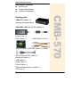
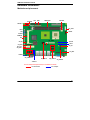
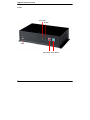
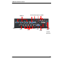
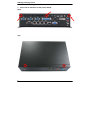
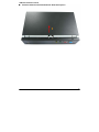
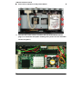
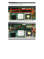
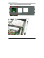
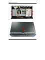
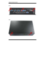
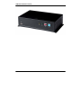
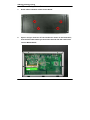
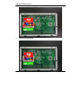
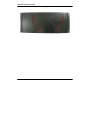
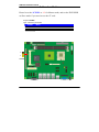
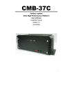
CMB-570 Installation Guide CMB-570 Mini Barebone system Intel High Performance Platform Installation Guide Edition 1.0 2008/03/06 9 CMB-570 Installation Guide Document Content: z z z Packing List Product Specification Hardware Installation CMB-570 Chassis x 1 (Including LS-570 Motherboard) DSPD-080-12A 80W AC-DC Adapter x 1 Power Cord x 1 CPU Cooler x 1 ATAPI Power Cord x1 44-pin to 44-pin ATA33 IDE Cable x1 (12CM) DVI module with DVI Cable x 1 Serial port Cable x 3 USB Cable x 1 Audio Cable x1 Printer Cable x 1 PS/2 Keyboard & Mouse Cable x 1 CD Driver x1 2 CMB-570 Packing List: CMB-570 Installation Guide Hardware Installation: Motherboard placement SYSFAN IDE FDD DDRII_A/B CPUFAN SATA1/2 DC_OUT JRTC JAT JFRNT JCFSEL MINIPCI PCI CN_LVDS JVLCD CN_IR CN_DIO JCRT CD_IN CN_INV CN_LPT CN_PS2 CN_DVI JCSEL1 CN_COM2/3/4 CN_HDTV CN_USB1/2 CN_AUDIO JCSEL2 For the Components placement,it is available for LS-570 For Connector For Jumper 3 CMB-570 Installation Guide I/O panel: Front: Power LED HD LED USB Reset Button Power Button 4 CMB-570 Installation Guide Rear: Printer Mouse Keyboard COM2/3/4 USB1/2 COM1 RJ45 VGA USB3/4 DVI Line-In DC-IN Line-Out Mic Phone 5 CMB-570 Installation Guide Chassis Setup procedure: 1. Screw off as indication of the picture below. Rear: Top: 6 CMB-570 Installation Guide 2. Push the Chassis shield towards the back then open it. 1 7 CMB-570 Installation Guide 3. Screw off as indication of the picture below. 4. Turn the CPU cooler screws and then refer the motherboard manual page.17 to install the CPU.(After installing CPU, please turn the CPU FAN screws to tighten.) 8 CMB-570 Installation Guide 6. Open the DIMM holder then check the pin number to match the socket side well before installing memory module. 7. Press down the memory module then check DIMM holder hook well. 9 CMB-570 Installation Guide 8. Put on HDD driver into HDD holder then turn the HDD drive screws to tighten.(If you don’t have HDD drive please direct to step.10) 9. Connect IDE cable from motherboard to the HDD drive. 10 CMB-570 Installation Guide 10. Screw on as indication of the picture below Turn the screws. 11. Push the Chassis shield towards the back then open it. 1 11 CMB-570 Installation Guide 12. Screw on as indication of the picture below. Rear: Top: 12 CMB-570 Installation Guide 13. Finish. 13 CMB-570 Installation Guide CF card Setup Procedure: 1. Screw off as indication of the picture below. 2. Open it and you shall see CF card socket. As shown in the illustration, face the label side toward you and insert the end with the small holes into the Motherboard. 14 CMB-570 Installation Guide 3. Follow the foolproof design then insert the CF card. 4. Check connected well 15 CMB-570 Installation Guide 5. 16 Close it shield and turn screw to tighten. CMB-570 Installation Guide Addendum Notice Please leave the JCFSEL as 1-2 for Master mode, and set the IDE2 HDD as Slave mode if you need to use the CF card. Jumper: JCFSEL Type: onboard 3-pin header JCFSEL Mode 1-2 Master 2-3 Slave Default setting 3 1 JCFSEL 17 CMB-570 Installation Guide Contact Information Any advice or comment about our products and service, or anything we can help you please don’t hesitate to contact with us. We will do our best to support you for your products, projects and business Taiwan Commate Computer Inc. Address 19F, No. 94, Sec. 1, Xintai 5th Rd., Xizhi Dist New Taipei City, Taiwan TEL +886-2-26963909 FAX +886-2-26963911 Website http://www.commell.com.tw TU UT [email protected] (General Information) TU UT E-Mail [email protected] (Technical Support) TU Facebook Twitter UT https://www.facebook.com/pages/Taiwan-Commate-Computer-Inc/547993955271899 https://twitter.com/Taiwan_Commate Commell is a brand name of Taiwan Commate Computer Inc. 18