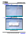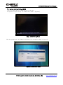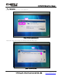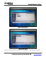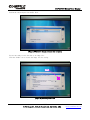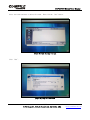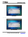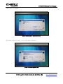
1
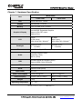
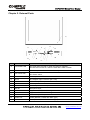
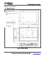
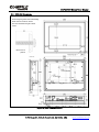
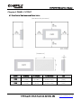
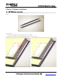
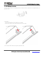
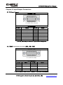
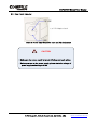
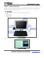
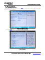
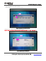
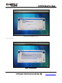
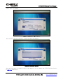
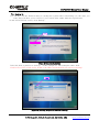
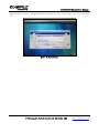
CUPC-P200 Series
User Manual
(P200, P220)
[Version 1.0]
COMFILE Technology Inc.
www.comfiletech.com
CUPC P200 Series User Manual
Table of Contents
Chapter 1. Hardware Specification ...................................................................................... 3
Chapter 2. External Parts .................................................................................................... 4
Chapter 3. Dimensions ......................................................................................................... 5
3-1. CUPC-P200 Dimensions............................................................................................. 5
3-2. CUPC-P220 Dimensions............................................................................................. 6
Chapter4. PANEL CUTOUT................................................................................................. 7
4-1 Installation Requirements and Installation.......................................................... 7
Chapter 5. Bracket Installation ............................................................................................ 8
5-1. CUPC-P200 Bracket Installation.................................................................................. 8
5-2. CUPC-P220 Bracket Installation.................................................................................. 9
Chapter 6. Input/Output Connectors .................................................................................. 10
6-1. VGA Output Connector............................................................................................... 10
6-2. RS232C Input/Output Connector (COM1, COM2, COM3)................................................. 10
6-3. Power Input Connector ......................................................................................... 11
Chapter 7. System Restoration .......................................................................................... 12
7-1. Getting Ready.......................................................................................................... 12
7-2. ROM Bios Configuration ....................................................................................... 13
7-2-1. Changing First Boot Device ............................................................................... 13
7-3. Booting with the WinClon SDCARD ........................................................................ 15
7-4. Restoration.......................................................................................................... 16
7-5. Backing Up ........................................................................................................... 21
MEMO ................................................................................................................................. 27
2/27
1175 Chess Dr., Suite F, Foster city, CA 94404, USA
www.comfiletech.com
CUPC P200 Series User Manual
Chapter 1. Hardware Specification
Model name
Item
CUPC-P200
CUPC-P220
Intel ATOM N270 1.6GHz
CPU
Chipset
Intel 945GSE + ICH7M
Memory
2GB SODIMM DDR2 SDRAM
Intel 945GSE Embedded Graphics
Support VGA CRT output
Support Pivot
Graphic & Display
15inch
16.7M Colors,
XGA(1024x768), 300cd/m2
10.4inch
262K Colors,
XGA(1024x768), 300cd/m2
Backlight
2Channel CCFL
LT : >50,000hr
1Channel CCFL
LT : >30,000hr
Ethernet
VIA VT6130 Gigabit Ethernet(2Port)
LCD
VIA High Definition Audio
Audio Out (1Port)
MIC In (1Port)
Audio
USB
Universal Serial Bus Support (4Port)
Support USB2.0 Host Controller
HDD
SATA HDD Interface
Serial
RS232C Serial (2Port)
DC+12V
Input Power
Power Consumption
Dimension(mm)
Weight
Operating Temperature
<32W (2.6A@12V)
<28W (2.3A@12V)
376(H) x 300(V) x 60(D)
280(H) x 300(V) x 60(D)
5.1Kg
2.5Kg
0℃ ~ 60℃
[Table 1] CUPC Hardware Specification
3/27
1175 Chess Dr., Suite F, Foster city, CA 94404, USA
www.comfiletech.com
CUPC P200 Series User Manual
Chapter 2. External Parts
Name
Description
A
Power/HDD LED
The green LED is turned on, when the power is supplied.
The red LED is turned on, when the hard disk is read or written.
B
ATX Power S/W
ATX mode power switch. Boot or exit the system.
C
Ext. Power S/W
The connector which can be linked to external switch. Same function with
ATX Power switch
D
Power S/W
Power input ON/OFF
E
DC IN
ø2.5 Adaptor Input Connector (DC +12V)
F
USB Port
USB1/USB2 (USB2.0)
G
VGA Port
VGA output for external monitor.
H
Audio Out
Sound output for external speaker
I
MIC IN
Microphone input
J
LAN2 Port
Support 100BaseT, with RJ-45 type connector
K
LAN1 Port
Support 100BaseT, with RJ-45 type connector
L
USB Port
USB3/USB4 (USB2.0)
M
COM1 Port
COM1 (RS232C, D-SUB 9Pin Male Type)
N
COM2 Port
COM2 (RS232C, D-SUB 9Pin Male Type)
4/27
1175 Chess Dr., Suite F, Foster city, CA 94404, USA
www.comfiletech.com
CUPC P200 Series User Manual
Chapter 3. Dimensions
3-1. CUPC-P200 Dimensions
Avoid using long bolts when
assembling VESA mounts or add-on
board.
The inner maximum length is about
12mm.
Back cover of
product
[Figure 1] CUPC-P200 Dimensions
5/27
1175 Chess Dr., Suite F, Foster city, CA 94404, USA
www.comfiletech.com
CUPC P200 Series User Manual
3-2. CUPC-P220 Dimensions
Avoid using long bolts when assembling
VESA mounts or add-on board.
The inner maximum length is about
10mm.
Back cover of
product
[Figure 2] CUPC-P220 Dimensions
6/27
1175 Chess Dr., Suite F, Foster city, CA 94404, USA
www.comfiletech.com
CUPC P200 Series User Manual
Chapter4. PANEL CUTOUT
4-1 Installation Requirements and Installation
[Installation Requirements]
[Installation]
CUPC
X (Width)
Y (Height)
T (Thickness)
Unit
P200
355
[13.98]
279
[10.99]
1.6 to 12.0
[0.06 to 0.47]
mm
[inch]
P220
263
[10.36]
210
[8.27]
1.6 to 6.0
[0.06 to 0.24]
mm
[inch]
7/27
1175 Chess Dr., Suite F, Foster city, CA 94404, USA
www.comfiletech.com
CUPC P200 Series User Manual
Chapter 5. Bracket Installation
5-1. CUPC-P200 Bracket Installation
To fasten CUPC-P200 to an upright panel, the brackets (left, right) are supplied when you purchase
P200.
* Procedure *
1) Push and install the CUPC-P200 into your panel.
2) Press the bracket as the following directions in two steps.
3) To fix the CUPC-P200 to the panel, fasten the bolts.
8/27
1175 Chess Dr., Suite F, Foster city, CA 94404, USA
www.comfiletech.com
CUPC P200 Series User Manual
5-2. CUPC-P220 Bracket Installation
To fasten CUPC-P220 to an upright panel, the brackets (left 2ea, right 2ea) are supplied when you
purchase P220.
* Procedure *
1) Push and install the CUPC-P220 into your panel.
2) Press the bracket as the following directions in two steps.
3) To fix the CUPC-P220 to the panel, fasten the bolts.
9/27
1175 Chess Dr., Suite F, Foster city, CA 94404, USA
www.comfiletech.com
CUPC P200 Series User Manual
Chapter 6. Input/Output Connectors
6-1. VGA Output Connector
Connector Type
* D-SUB 15Pin Female
Pin Assignment
Pin No.
Signal
Pin No.
Signal
1
RED
2
GREEN
3
BLUE
4
5
GND
6
GND
7
GND
8
GND
9
DDC VCC (+5V)
10
GND
11
12
DDC DATA
13
HSYNC
14
VSYNC
15
DDC CLK
[Table 2] VGA Output Connector Type and Pin Assignment
6-2. RS232C Input/Output Connector (COM1, COM2, COM3)
Connector Type
*D-SUB 9Pin Male
Pin Assignment
Pin No.
Signal
Pin No.
Signal
1
DCD
2
RXD
3
5
TXD
GND
4
6
DTR
DSR
7
RTS
8
CTS
9
RI
-
-
[Table 3] RS232C Input/Output Connector Type and Pin Assignment
10/27
1175 Chess Dr., Suite F, Foster city, CA 94404, USA
www.comfiletech.com
CUPC P200 Series User Manual
6-3. Power Input Connector
* ø 2.5 Adaptor Jack
[Figure 3] Power Input Connector Type and Pin Assignment
!
CAUTION
- Make sure the power supply is turned off when you begin wiring.
- Before you turn on the power supply, please check the voltage of
power supply and wiring is all ok.
11/27
1175 Chess Dr., Suite F, Foster city, CA 94404, USA
www.comfiletech.com
CUPC P200 Series User Manual
Chapter 7. System Restoration
CUPC provides a system restoration solution using Clonix’s WinClon, which is included when you
purchase the OS Option Package. You can restore the CUPC to its original state or to any state you
may have saved using the backup procedure.
7-1. Getting Ready
In order to perform the restoration procedure, the following is needed.
- CUPC
- Recovery SDCARD
- Keyboard & Mouse
- DC Power(+12V)
CUPC
Recovery
SDCARD
DC
Power
USB Mouse
USB
Keyborad
[Figure 4] Getting Ready
Please be sure to use the recovery SDCARD with the WinClon logo.
[Figure 5] Recovery SDCARD
12/27
1175 Chess Dr., Suite F, Foster city, CA 94404, USA
www.comfiletech.com
CUPC P200 Series User Manual
7-2. ROM Bios Configuration
7-2-1. Changing First Boot Device
After turning on the power, if you press the [F2] key on the initial screen, the BIOS Setup Utility
will open as shown in Figure 6.
[Figure 6] BIOS SETUP Initial Screen
Select the [Boot] menu.
[Figure 7] Boot Menu
13/27
1175 Chess Dr., Suite F, Foster city, CA 94404, USA
www.comfiletech.com
CUPC P200 Series User Manual
Select the [USB KEY] and move it to the top of the list using [+] key.
Select [Exit Saving Changes] in the [Exit] menu.
[Figure 8] BIOS SETUP Exit Screen
Select [YES] in the [Setup Confirmation] screen.
[Figure 9] Setup Exit Confirmation Screen
14/27
1175 Chess Dr., Suite F, Foster city, CA 94404, USA
www.comfiletech.com
CUPC P200 Series User Manual
7-3. Booting with the WinClon SDCARD
Insert the WinClon Recovery SDCARD and turn on the power.
The System will begin booting into Windows PE as shown in [Figure10].
[Figure 10] WinPE Booting Screen
After the system boots into Windows PE, WinClon will be executed as shown in [Figure 11]
[Figure 11] WinClon Initial Screen
15/27
1175 Chess Dr., Suite F, Foster city, CA 94404, USA
www.comfiletech.com
CUPC P200 Series User Manual
7-4. Restoration
On the initial WinClon screen, click ‘Restore’.
Click
[Figure 12] Restoring Menu Selection
Select the restoration image according to the following steps.
Click
[Figure 13] Selecting Image
16/27
1175 Chess Dr., Suite F, Foster city, CA 94404, USA
www.comfiletech.com
CUPC P200 Series User Manual
Click on the folder icon.
[Figure 14] Exploring image file
[Figure 15] Select image file
In the SD card you purchased, you will find an initial restoration image named by CUPC model.
you have performed a backup, you may see your own image, too. Select an image from the list.
17/27
1175 Chess Dr., Suite F, Foster city, CA 94404, USA
If
www.comfiletech.com
CUPC P200 Series User Manual
Select the partition you want to restore.
In this example, we will restore the entire disk.
Check
[Figure 16] Selecting the restoring partition
Click the ‘Next’ button and select the disk to restore.
(Caution: Make sure that you confirm the disk information and check if it says ‘Hard Disk’)
Check
[Figure 17] Selecting the restoring disk
18/27
1175 Chess Dr., Suite F, Foster city, CA 94404, USA
www.comfiletech.com
CUPC P200 Series User Manual
Click ‘Next’.
[Figure 18] Restoring Summary Screen
Click ‘Process’.
[Figure 19] Continue Screen
19/27
1175 Chess Dr., Suite F, Foster city, CA 94404, USA
www.comfiletech.com
CUPC P200 Series User Manual
Click ‘Yes’ to confirm.
[Figure 20] Restoration Progress Screen
The restoration process will begin. It will take about 4~5 minutes..
[Figure 21] Restoration complete
After the restoration is complete, refer to the chapter 7-2-1 to change the CUPC First Boot Device
to IDE HDD and reboot.
20/27
1175 Chess Dr., Suite F, Foster city, CA 94404, USA
www.comfiletech.com
CUPC P200 Series User Manual
7-5. Backing Up
You can also use the WinClon utility to backup the system after customizing it to the state you
want. This will allow you to restore to your custom state rather than the original state.
On the initial WinClon screen, click ‘Backup’.
Click
[Figure 22] Selecting Backup Menu
Select the disk or partition to back up. In this example we will backup the entire disk.
(Caution: For CUPC-P200 series, Disk2 is the HDD. Check the disk size before selecting.)
Click
[Figure 23] Selecting the partition and disk to back up
21/27
1175 Chess Dr., Suite F, Foster city, CA 94404, USA
www.comfiletech.com
CUPC P200 Series User Manual
Confirm the selected partition and/or disk.
[Figure 24] Confirm the partition and disk to back up
You are now ready to save the disk to an image file.
Click the folder icon to locate the image file for saving.
Click
[Figure 25] Selecting folder icon
22/27
1175 Chess Dr., Suite F, Foster city, CA 94404, USA
www.comfiletech.com
CUPC P200 Series User Manual
Select the folder and enter a desired file name. Then click the ‘Save’button.
[Figure 26] Input the image file name
Click ‘Next’.
[Figure 27] Image file determined
23/27
1175 Chess Dr., Suite F, Foster city, CA 94404, USA
www.comfiletech.com
CUPC P200 Series User Manual
If you want to protect your image, enter your password and click ‘Next’.
[Figure 28] Password set
Click ‘Process’.
[Figure 29] Backup Summary Screen
24/27
1175 Chess Dr., Suite F, Foster city, CA 94404, USA
www.comfiletech.com
CUPC P200 Series User Manual
Click ‘Yes’ to confirm.
[Figure 30] Backup Start Confirmation Screen
The backup process will begin. It will take about 5~6 minutes.
[Figure 31] Backup Progress Screen
25/27
1175 Chess Dr., Suite F, Foster city, CA 94404, USA
www.comfiletech.com
CUPC P200 Series User Manual
When the backup process is finished WinClon will display the newly created image file. To finish, click
‘OK’.
[Figure 32] Backup Complete
26/27
1175 Chess Dr., Suite F, Foster city, CA 94404, USA
www.comfiletech.com
CUPC P200 Series User Manual
MEMO
27/27
1175 Chess Dr., Suite F, Foster city, CA 94404, USA
www.comfiletech.com