1
System
Installation
Guide
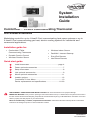
ComfortNet™ CTK04 Communicating Thermostat
With wireless accessories
Modulating control for up to 4 Heat/2 Cool communicating heat pump systems or up to
3 Heat/2 Cool communicating gas heat, electric cooling systems for residential and
commercial applications.
Installation guide for:
• ComfortNet CTK04
Communicating Thermostat
• Wireless Indoor Sensor
• Portable Comfort Control
• Entry/Exit Remote
• Wireless Outdoor Sensor
• RedLINK Internet Gateway
™
• Vent Boost Remote
Quick start guide
1
Install thermostat...........................................................page 4
2
Power optional accessories.................................................... 7
3
Setup thermostat.................................................................... 8
4
Link optional accessories....................................................... 9
5
Mount optional accessories.................................................. 11
6
Installer options.................................................................... 12
ComfortNet™ User Menu..................................................... 13
Device replacement and specifications...........................21-23
DISCONNECT POWER BEFORE INSTALLATION. Can cause electrical shock or equipment damage.
MERCURY NOTICE: If this product is replacing a control that contains mercury in a sealed tube, do not place the old control in
the trash. Contact the Thermostat Recycling Corporation at www.thermostat-recycle.org or 800-238-8192 for information on how and
where to properly and safely dispose of your old thermostat.
Must be installed by a trained, experienced technician. Read these instructions carefully. Failure to follow these
instructions can damage the product or cause a hazardous condition.
69-2688-07
I/O-CHTSTAT03
System Installation Guide
The ComfortNet advantage
The premium Honeywell ComfortNet™ control system is easy to use, energyefficient, reliable and ensures the system is set up properly. Advanced operating
algorithms built into the control delivers efficient equipment operation while providing
optimal comfort. The Honeywell ComfortNet Communicating thermostat is designed
to regulate and communicate with the central heating and cooling equipment and has
the ability to share information so the user will enjoy efficient, economical comfort
throughout the home.
RedLINK™ Compatible
RedLINK accessories include the Wireless Outdoor Sensor, Portable Comfort Control
(PCC), RedLINK Internet Gateway, Wireless Indoor Sensor, TrueSTEAM™ humidifier
with Wireless Adapter, Vent Boost Remote and Entry/Exit Remote.
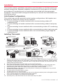
Customizable Service Reminders
Set up to 10 service reminders. Choose from pre-set options or customize your own.
Pre-set reminder options include filter replacement, humidifier maintenance, dehumidifier filter, ventilator filter, UV bulb replacement, annual service, spring service,
fall service and warranty expiring soon. Reminders based on the date or outdoor
temperature will be displayed on the thermostat's main screen along with pre-set or
custom instructions.
User Interactions Log
The interaction log stores history of thermostat setting changes including temperature, system and installer setup. You can use the interaction log to save time by
determining if the issue is a system error or an accidental user error.
Configurable for Residential and Light Commercial Applications
One thermostat does it all to meet the needs of Residential and Light Commercial
applications. Simply select Residential or Commercial during the installer setup. If
Commercial is selected, the thermostat will use commercial language, meet building
codes and offer 365 day holiday scheduling.
USB Port
Visit http://thermostatsetup.honeywell.com to enter your dealer information and save
to a USB stick. Then load your dealer information and logo to multiple thermostats.
After setting up a thermostat, save Installer Setup, Holiday / Event Scheduler and
Custom Reminders to a USB stick. Then load this information to multiple thermostats.
To use the USB port, insert a USB stick in the bottom of the thermostat. Then select
the item you would like to load or save.
Selectable Sensors
When paired with a Wireless Indoor Sensor(s) you have the ability to choose which
sensor(s) to use for temperature, humidification and dehumidification. They can be
used in combination for temperature averaging—or individually—to condition humidity
levels in separate spaces.
69-2688—07 I/O-CHTSTAT03
2
CTK04 ComfortNet™ Communicating Thermostat
Installation
This booklet contains installation instructions and information on the thermostat and
wireless accessories. Separate installation instructions for the furnace or air handler
and outdoor AC condensing unit or heat pump are provided with the appropriate
equipment. This thermostat is designed exclusively for use with the ComfortNet communicating system.
Valid System Configurations
This control may only be used with certain system configurations. Valid system configurations for which this control can be used are:
• A communicating air handler matched with a communicating outdoor AC
condensing unit.
• A communicating air handler matched with a communicating outdoor heat pump
unit.
• A communicating furnace matched with a communicating outdoor AC condensing
unit.
• A communicating furnace matched with a communicating outdoor heat pump unit.
• A communicating furnace matched with a non-communicating single stage AC
condensing unit.
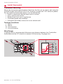
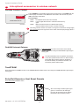
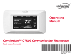
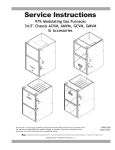
Installing Thermostat
1
REMOVE AND INVENTORY ALL
COMFORTNET™ COMPONENTS
2
INSTALL HVAC COMPONENTS
3
REMOVE 9-PIN CONNECTOR
FROM FURNACE OR AIR
HANDLER CONTROL
P/N
AIR
HANDLER
F0
43
06
GAS
FURNACE
73
00
5
CONNECT 4-WIRES
FROM STAT AND
2 WIRES FROM
OUTDOOR UNIT
AIR CONDITIONER
OR HEAT PUMP
AIR CONDITIONER
OR HEAT PUMP
NOTE: THE CTK04 CONTAINS THE THERMOSTAT, LITHIUM COIN CELL BATTERY,
WALL MOUNTING SCREWS AND ANCHORS, SYSTEM INSTALLATION GUIDE,
OPERATING MANUAL, TRANSFORMER AND A WIRING SET THAT INCLUDES
TWO TERMINAL BLOCKS AND WIRES.
CONNECT TO THE OUTDOOR UNIT
5 2-WIRE/TRANSFORMER
CONNECTION
CONNECT 2-WIRES TO
REMOVE OUTDOOR UNIT
INDOOR UNIT
4 COVER AND 7-PIN
ADDITIONAL TRANSFORMER
CONNECTOR
IS NOT REQUIRED FOR
P/N
F0
43
06
75
00
5
INVERTER/VARIABLE SPEED
OUTDOOR COMMUNICATING
UNITS.
ADDITIONAL TRANSFORMER
IS REQUIRED FOR 2-STAGE
OUTDOOR COMMUNICATING
UNITS.
HIGH
VOLTAGE
LOW (24 VAC)
VOLTAGE
TRANSFORMER LOW
VOLTAGE CONNECTED
TO R AND C
TERMINALS
P/N F0430679005
6
TERMINALS 1 & 2 ARE
COMMUNICATIONS
WIRES. THEY SHOULD
NEVER BE CONNECTED
TO THE 24 VAC R&C
POWER SUPPLY
TERMINALS.
INSTALL THERMOSTAT ON INTERIOR WALL
NOTE: THERMOSTAT WILL
AUTOMATICALLY CONFIGURE
TO THE SYSTEM ONCE HIGH
VOLTAGE POWER IS
APPLIED TO THE
INDOOR AND
OUTDOOR
EQUIPMENT.
TRANSFORMER
CONNECT HIGH VOLTAGE TRANSFORMER LEADS TO L1
AND L2 MALE SPADE TERMINALS ON CIRCUIT BOARD.
DO NOT CONNECT R AND C BETWEEN THE INDOOR UNIT
AND OUTDOOR UNIT. SEE PAGE 5.
M33487B
1.
Remove and inventory all ComfortNet components. The CTK04 contains the ComfortNet communicating thermostat, lithium coin cell battery, wall mounting screws and anchors, system installation guide, operating manual, transformer and a wiring set that includes two terminal blocks, two
sheet metal screws and wires.
2. Carefully separate the thermostat body from the thermostat base.
3. Place base at installation location and mark mounting hole locations on wall using base as a
template. See Thermostat Mounting section on next page for optimal mounting location.
4. Drill mounting holes. Drill 3/16" holes for drywall and 7/32" holes for plaster.
5. Attach base firmly to wall using two mounting screws. Leveling is for appearance only and will
not affect thermostat operation.
6. Connect wires to terminal block on base.
7. 18 AWG solid wire is recommended.
8. Push excess wire into wall and plug hole with a fire resistant material (such as fiberglass insulation) to prevent drafts from affecting thermostat operation.
9. Insert coin cell battery in the back of the thermostat.
10. Carefully line up the thermostat with the base and snap into place.
3
I/O-CHTSTAT03 69-2688—07
System Installation Guide
1
Install thermostat
Thermostat Mounting
Mount the thermostat approximately 5 feet from the floor on an interior wall using the
included screws and anchors. Drill 3/16" holes for drywall and 7/32" holes for plaster.
Do not install the thermostat where it can be affected by:
• Drafts or dead spots behind doors and in corners.
• Hot or cold air from ducts.
• Radiant heat from sun or appliances.
• Concealed pipes and chimneys.
• Unheated (uncooled) areas such as an outside wall.
Terminal Functions:
1 - Data 1
2 - Data 2
R - 24 volt power
C - 24 volt common
Wire Gauge:
18 gauge wire is recommended. Maximum wire distance between the ComfortNet
thermostat and the IFC should not exceed 100 feet using 18 gauge wire.
1
2
R
C
1
2
R
C
MCR29241
MCR33170
69-2688—07 I/O-CHTSTAT03
4
MCR33171
CTK04 ComfortNet™ Communicating Thermostat
1
Install thermostat
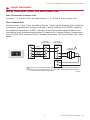
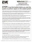
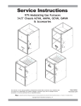
Wiring Thermostat, Indoor Unit and Outdoor Unit
Wire Thermostat to Indoor Unit
Connect 1, 2, R and C from the thermostat to 1, 2, R and C at the Indoor Unit.
Wire Outdoor Unit
Connect wires 1 and 2 from the Indoor Unit to 1 and 2 at the Outdoor Unit. Install the
transformer provided and connect to R and C at the Outdoor Unit. (NOTE: installing
the additional transformer is NOT required for inverter/variable speed outdoor communicating units. Additional transformer IS required for 2-stage outdoor communicating units.) Do NOT connect R and C between the Indoor Unit and Outdoor Unit. See
below.
CTK04
1
2
R
C
INDOOR
BOARD TERMINAL
CONNECTIONS
OUTDOOR
BOARD TERMINAL
CONNECTIONS
1
1
2
2
R
R
C
C
DATA 1
DATA 2
24VAC (HOT)
24VAC
(COMMON)
OUTDOOR 1
TRANSFORMER
24VAC
240V
L1
L2
1
INSTALLING THE ADDITIONAL TRANSFORMER IS NOT REQUIRED FOR INVERTER/VARIABLE
SPEED OUTDOOR COMMUNICATING UNITS. ADDITIONAL TRANSFORMER IS REQUIRED FOR
2-STAGE OUTDOOR COMMUNICATING UNITS.
M33168C
5
I/O-CHTSTAT03 69-2688—07
System Installation Guide
2
Power optional accessories
[If no wireless accessories are used, skip to Section 3.]
Outdoor air sensor
Indoor air sensor
MCR32938
MCR32937
Install 2 fresh AA lithium batteries
Install 2 fresh AAA alkaline batteries
Portable Comfort Control
MCR32939
Install 3 fresh AA alkaline batteries
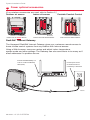
RedLINK™ Internet Gateway
The Honeywell RedLINK Internet Gateway gives your customers remote access to
home climate-control systems from any location with Internet access.
Using a Web browser, users can review and adjust indoor temperature,
system mode and other settings. The Gateway can also send alerts to as many as 6
email addresses if a problem occurs.
Connect RedLINK Gateway to a
router or modem with Ethernet
cable (RJ45).
Connect power cord to
an electrical outlet not
controlled by a wall switch
M32940
69-2688—07 I/O-CHTSTAT03
6
CTK04 ComfortNet™ Communicating Thermostat
2
Power optional accessories
TrueSTEAM
Connect the ABCD terminals between TrueSTEAM and the THM4000 Wireless
Adapter.
Adjust the DIP Switches on TrueSTEAM as follows when using the Wireless Adapter:
DIP3: UP
DIP4: UP
TrueSTEAM
DIP5: DOWN
THM4000R1000
1
2
3
4
5
6
ON
OFF
MCR31476
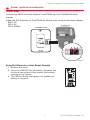
Entry/Exit Remote or Vent Boost Remote
1 Remove the cover.
2 Insert the CR2450 coin cell battery (included) into
the slot at the bottom of the remote. See polarity
marking on the remote.
3 The LED will briefly flash green. If it flashes red,
battery is not good.
MCR33269
7
I/O-CHTSTAT03 69-2688—07
System Installation Guide
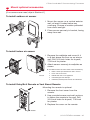
3
Setup thermostat
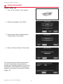
Initial Power Up
1 Turn on AC power to the system.
2 Select Language. Press Next.
3 Select Application (Residential or
Commercial). Press Next.
4 Enter a Device Name. Press Next.
The thermostat will automatically identify the ComfortNet communicating
equipment installed and then you will be
prompted to add RedLINK accessories
(page 9) and setup the Installer Options
(page 12).
69-2688—07 I/O-CHTSTAT03
8
CTK04 ComfortNet™ Communicating Thermostat
4
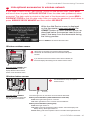
Link optional accessories to wireless network
If you need to return to the "Add Device" screen to add devices later, press MENU
and scroll down to press INSTALLER OPTIONS. Enter the date code (password) when
prompted. The date code is printed on the back of the thermostat; or press MENU >
EQUIPMENT STATUS to find the date code. After you enter the password, scroll down to
press WIRELESS DEVICE MANAGER and then select ADD DEVICE.
While the Add Device screen is displayed
on the thermostat, press and release the
CONNECT button on each wireless device, as
described below. Accessories need to be at
least 2 feet away from the thermostat during
the linking process.
Press DONE after all devices have been linked
Wireless outdoor sensor
When power is interrupted, the equipment and the RedLINK
accessories will automatically restore communication after power
resumes.
If you have both a wired and wireless outdoor sensor installed, the
thermostat displays the reading from the wireless outdoor sensor.
MCR28847A
Press and release CONNECT. After
a short delay the thermostat will
display "Wireless Outdoor Sensor
added" on the Add Device screen.
Wireless indoor sensor
The thermostat can use up to 6 optional
wireless sensors.
MCR32934
Press and release CONNECT.
After a short delay, the status light
will glow green for 15 seconds.
MCR32935
If the status light turns red, the sensor did not link with the thermostat.
Battery level indicators (when batteries are inserted)
Good: Status light flashes green for 5 seconds.
Low: Status light flashes red for 5 seconds. Use fresh batteries.
Battery level indicators (during use)
Good: Status light remains off.
Low: Battery power will be depleted in about 2 months. Thermostat displays Low
Battery warning. Status light remains off.
Critical: Battery power will be depleted in about 2–3 weeks. Status light flashes red.
9
I/O-CHTSTAT03 69-2688—07
System Installation Guide
4
Link optional accessories to wireless network
Portable Comfort Control
CONNECT
WIRELESS SETUP
MCR32942
Press CONNECT on the Portable Comfort Control display screen. Press DONE when the
screen displays "Connected." Press NO at the next screen to save and exit. (Or press
YES to link another thermostat.)
Error messages:
E1 29 Incompatible device cannot be connected.
E1 34 Low RF signal. Move device to a different location and try again.
E1 38 Make sure the thermostat is in Wireless Setup mode,
and the Portable Comfort Control is at least 2 feet away.
The linking procedure will time out if there is no keypress for 30 minutes. To begin again,
press and hold in the lower right corner of the screen until the display changes (about 3
seconds).
RedLINK Internet Gateway
Press and release the button on the bottom of the Internet
Gateway. After a short delay, the RedLINK status light will glow
steady green.
MCR32943
The Internet Gateway must be registered online before
use at www.mytotalconnectcomfort.com. Enter the MAC
ID and MAC CRC numbers located on the bottom of
the Internet Gateway. For additional information, see
instructions provided with the device.
TrueSTEAM
Press and release the CONNECT button on the THM4000 Wireless Adapter. After a short delay, the CONNECTED status light will glow
steady green..
Entry/Exit Remote or Vent Boost Remote
Press and release CONNECT button.
After a short delay, the status light will glow
green for 15 seconds. If the status light
turns red, the remote did not link with the
thermostat for the connection process.
69-2688—07 I/O-CHTSTAT03
MCR33096
10
CTK04 ComfortNet™ Communicating Thermostat
5
Mount optional accessories
[If no sensors are used, skip to Section 6.]
To install outdoor air sensor
1 Mount the sensor on a vertical exterior
wall, at least 6 inches below any
overhang. Choose a location protected
from direct sunlight.
2 Place sensor securely in bracket, facing
away from wall.
M28491
M28849A
To install indoor air sensor
1 Remove the wallplate and mount it 4
to 6 feet above the floor on an interior
wall. Drill 3/16-inch holes for drywall,
7/32-inch for plaster.
2 Attach sensor securely to wallplate as
shown.
Do not install the indoor air sensor where it can be affected by:
• Drafts or dead spots behind doors and in corners.
• Hot or cold air from ducts.
• Radiant heat from sun or appliances.
• Concealed pipes and chimneys.
• Unheated (uncooled) areas such as an outside wall
M32936B
To install Entry/Exit Remote or Vent Boost Remote
Mounting the remote is optional.
1 Remove the front cover from the
remote.
2 Use provided screws and wall anchors
to fasten the remote to the wall. Drill
3/16-inch holes for drywall, 7/32-inch
for plaster.
3 Replace the cover on the remote.
M33095
11
I/O-CHTSTAT03 69-2688—07
System Installation Guide
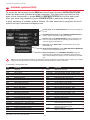
6
Installer options (ISU)
To setup the thermostat, press MENU and scroll down to press INSTALLER OPTIONS.
Enter the date code (password) when prompted. The date code is printed on the
back of the thermostat; or press MENU > EQUIPMENT STATUS to find the date code.
After you enter the password, press CREATE SETUP to setup the thermostat.
A brief summary of installer options follows. You can download a complete list of all
options at http://customer.honeywell.com.
Create Setup: Press CREATE SETUP to set all system settings one
by one.
View/Edit Current Setup: Press VIEW/EDIT CURRENT SETUP to
select a specific function and make quick changes.
Installer Test: Press INSTALLER TEST to quickly determine if the
heat, cool, fan and thermostat are operating properly. Minimum off
timers are ignored during the test.
Data Logs: Press DATA LOGS to view the Alerts Log and User
Interactions Log.
Wireless Device Manager: Press WIRELESS DEVICE MANAGER
to add or remove wireless accessories.
Advanced Options: Press ADVANCED OPTIONS to setup the
thermostat using a USB device or to restore the thermostat to the
factory default settings. See page 2 for more information on the USB
port.
TIP: You can use the thermostat USB port to download all system configuration and installer options, including your company
name and contact information. You can upload this data to each thermostat you install, to save time.
R: Residential C: Commercial B: Both
ISU
Function
1000Language
1010Residential/Commercial
1030
Device Name
1030
Device Name on Home Screen
1040Programmable/Non-programmable
1050Fahrenheit/Celsius
1060
Outdoor Air Sensor
2000
Heating System Type
2010
Heating Equipment Type
2070
Heat Stages
2070
Cool/Compressor Stages
2070
Backup Heat Stages
2180
Backup Heat Type
2190
System Zoning - Backup Heat Control
3000
Manual/Auto Changeover
3000
Auto Changeover Deadband
3010
Temperature Control Options
3020
Finish With High Cool Stage
3021
Finish With High Heat Stage
3030
Staging Control - Cool Differentials
3050-3060 Staging Control - Heat Differentials
3090
Staging Control - Backup Heat Differentials
3110
Backup Heat Upstage Timer
3120
Outdoor Compressor Lockout
3120
Outdoor Backup Heat Lockout
3140
Cool/Compressor Cycles Per Hour
69-2688—07 I/O-CHTSTAT03
ISU
3150
3160
3170-3190
3200-3220
3240
3260
3260
4000
4010
4020
4030
4050
4060
4070
4080
4090
4100
4100
4110
4120
B
B
B
C
B
B
B
B
B
B
B
B
B
B
B
B
B
B
B
B
B
B
B
B
B
B
4120
4130
12
Function
Heat Cycles Per Hour
Backup Heat Cycles Per Hour
Cooling Derivative, Integral, Throttling range
Heating Derivative, Integral, Throttling range
Minimum Compressor Off Time
Extended Fan Run Time in Cool
Extended Fan Run Time in Heat
Number of Schedule Periods
Pre-occupancy Purge Duration
Override: Standard or Initiate Occupancy
Override Duration
Minimum Recovery Settings - Heat
Maximum Recovery Settings - Heat
Minimum Recovery Settings - Cool
Maximum Recovery Settings - Cool
Adaptive Intelligent Recovery
Minimum Cool Setpoint
Maximum Heat Setpoint
Keypad Lockout
Entry/Exit Remote Home/Occupied Cool Setpoint
Entry/Exit Remote Home/Occupied Heat Setpoint
Entry/Exit Remote Away/Unoccupied Cool Setpoint
B
B
C
C
B
B
B
B
C
C
C
C
C
C
C
R
B
B
B
B
B
B
CTK04 ComfortNet™ Communicating Thermostat
Installer options (ISU)
6
ISU
4130
4140
4140
5040
7000
7020
7110
7110
7120
7120
7120
8000
8010
8050
8060
8070
8100
8100
9000
9010
9020
9070
9080
9090
Function
ISU
Entry/Exit Remote Away/Unoccupied Heat Setpoint
B
Entry/Exit Remote Vacation/Holiday Cool Setpoint
B
Entry/Exit Remote Vacation/Holiday Heat Setpoint
B
Indoor Sensors Used for Temperature Control B
Filter Type
B
Number of Air Filters
B
Air Filter Replacement Reminder
B
Air Filter 2 Replacement Reminder
B
EAC Cell Cleaning Reminder
B
EAC Pre-Filter Cleaning Reminder
B
EAC Post-Filter Replacement Reminder
B
Humidifier Type
B
Indoor Sensor Used for Humidification Control B
Humidification - Window Protection
B
System Modes Allowing Humidification
B
Humidification Control
B
Clean Tank / Water Filter Replacement ReminderB
Humidifier Pad Replacement Reminder
B
Dehumidification Equipment
B
Indoor Sensor Used for Dehumidification Control B
Humidity Sensor Displayed on the Home Screen B
Dehumidification - Overcooling Limit
R
Dehumidification Control
C
Dehumidification Minimum On Time
C
9100
9180
9190
9200
Function
High Humidity Comfort Reset Setting
Dehumidification Away Mode
Dehumidification Away Mode - Fan Control
Dehumidification Away Mode Low Limit Temperature
9200
Dehumidification Away Mode Temperature Setting
9200
Dehumidification Away Mode Dehumidification Setting
9210
Dehumidifier Filter Replacement Reminder
10000
Ventilation Type
10050
Ventilation Control Method
10090
Number of Bedrooms
10090
Size of House
10100
Enter Equipment Ventilation Rate
10120
Ventilation Percent On Time
10170
Ventilator Filter Cleaning Reminder
11000
Number of UV Devices
11050
UV Bulb Replacement Reminder
11050
UV Bulb 2 Replacement Reminder
12000
Installer Custom Reminders
14000
Clock Format
14010
Daylight Saving Time
14020
Indoor Temperature Display Offset
14020
Indoor Humidity Display Offset
15000-15020Dealer name, phone, email, website, message
C
B
B
B
B
B
B
B
B
R
R
R
B
B
B
B
B
B
B
B
B
B
B
ComfortNet User Menu
Press MENU > COMFORTNET USER MENU
Additional equipment information is found in the ComfortNet User Menu. Press MENU
and scroll down to press COMFORTNET USER MENU. Enter the date code (password)
when prompted. The date code is printed on
the back of the thermostat; or press MENU >
EQUIPMENT STATUS to find the date code.
After you enter the password, select the
equipment type (furnace, air handler,
air conditioner, heat pump) to view the
specifications.
Each equipment type is divided into categories
which may include: (Not all menu options listed
here may be available. Additional menu options may be displayed on the thermostat.)
• Configuration: Provides information regarding the setup of the equipment. An example of configuration data is the number
of cooling stages for an AC condensing unit.
• Diagnostics: Provides a fault history of the equipment and allows the installer to clear the fault history.
• Identification: Provides the model and serial number of the equipment and software revision information.
• Sensors: Provides the sensor data of the equipment. In some instances, it may allow the installer to setup or turn off a
sensor.
• Setup: Allows the installer to change the settings of the equipment.
• Status: Provides the current status of the equipment.
See equipment installer manual for specific submenu options available within each
category. Both indoor (Air Handler and Furnace) and outdoor (Air Conditioner and
Heat Pump) units will have different sets of submenus.
13
I/O-CHTSTAT03 69-2688—07
System Installation Guide
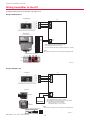
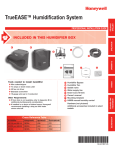
Wiring humidifier to the IFC
To change installer setup (ISU) information, see pages 12-13.
Wiring TrueSTEAM to IFC
THERMOSTAT
IFC
1
2
R
C
1
2
R
C
TRUESTEAM
24 V
24 V
HUM
HUM
HUM
HUM
C
GT
R
RT
1. WIRE THERMOSTAT AND TrueSTEAM AS SHOWN.
2. SET THERMOSTAT ISU 8000 TO “STEAM”.
3. SET TrueSTEAM DIP SWITCHES AS SHOWN (3 DOWN, 4 UP, 5 DOWN).
GF
EXT
NOTE
FAN INTERLOCK IS HANDLED BY THE COMFORTNET COMMUNICATION.
TrueSTEAM DIP SWITCHES
1
3
2
4
5
6
ON
OFF
MCR33172
AFS MONITOR RECOMMENDED
Wiring TrueEASE to IFC
THERMOSTAT
IFC
1
1
2
2
R
R
C
C
TrueEASE
HUM
HUM
BYPASS
HUM
CONTROL
FAN
POWERED
TrueEASE DIP SWITCHES
1. WIRE THERMOSTAT AND TrueEASE AS SHOWN.
2. SET THERMOSTAT ISU 8000 TO “BYPASS OR FAN POWERED”.
3. SET TrueEASE DIP SWITCHES AS SHOWN :
• TOP DIP SWITCH – SET TO THE RIGHT
• BOTTOM DIP SWITCH – SET TO THE LEFT
NOTE
FAN INTERLOCK IS HANDLED BY THE COMFORTNET COMMUNICATION.
MCR33173
69-2688—07 I/O-CHTSTAT03
14
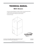
CTK04 ComfortNet™ Communicating Thermostat
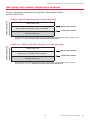
Heat pump with outdoor temperature lockouts
Outdoor temperature lockouts are optional. See Installer Setup
options (ISU 3120).
Outdoor temperature
Electric - Backup heat allowed to run with heat pump
Heat pump only
Backup heat lockout
Heat pump with backup heat as needed *
Compressor lockout
Backup heat only
*
No backup heat unless indoor temperature drops to selected Backup Heat Differential setting, or Backup Heat
Upstage Timer expires. Heat pump stays ON when backup heat turns on.
Outdoor temperature
Fossil Fuel - Backup heat NOT allowed to run with heat pump
Heat pump only
Backup heat lockout
Heat pump or backup heat operates *
Compressor lockout
Backup heat only
*
No backup heat unless indoor temperature drops to selected Backup Heat Differential setting, or Backup
Heat Upstage Timer expires. Heat pump turns OFF when backup heat turns on.
15
I/O-CHTSTAT03 69-2688—07
System Installation Guide
Basic and Advanced Temperature Control Options (ISU 3010)
Basic Options: The Installer Setup displays basic temperature control options
which include Backup Heat Differential, Backup Heat Upstage Timer and Outdoor
Temperature Lockouts. Note: Outdoor Temperature Lockouts only apply to Heat
Pump applications.
Advanced Options: The Installer Setup displays both Basic and Advanced Options.
Advanced temperature control options include Finish With High Cool Stage, Finish
With High Heat Stage, Temperature Differential settings between all stages and
Cycle Rate settings per stage.
Finish With High Heat or Cool Stage - When a multi-stage heating or cooling system is used, this feature keeps the high stage
of the heating or cooling equipment running until the desired setpoint is reached.
Backup heat differential and upstage timer
A backup heat differential and backup heat upstage timer can be set on heat pump
systems with backup heat. See installer setup options (ISU 3090-3110).
Normal operation
When the Backup Heat Differential is set to Comfort, the thermostat uses backup
heat as needed to keep the indoor temperature within 1° F (0.5° C) of the setpoint.
When the Backup Heat Differential is set to 2° F or higher, backup heat is not used
unless the indoor temperature drops to the Backup Heat Differential setting or the
Backup Heat Upstage Timer expires, whichever occurs first. The upstage timer starts
when the highest stage of the previous equipment type turns on.
Manual temperature change
When the Backup Heat Differential is set to Comfort, the thermostat uses backup
heat as needed to keep the indoor temperature within 1° F (0.5° C) of the setpoint.
When the Backup Heat Differential is set to 2° F or higher, if the heat pump is making progress as expected, backup heat will not be used to reach the new setpoint.
Set to a higher number to use less backup heat (a greater difference between the
current indoor temperature and the new setpoint is required to turn on backup heat).
See notes below.
Programmed recovery
If the heat pump is making progress as expected, backup heat will not be used to
reach the setpoint of the next program period. Backup heat is always restricted during a programmed recovery when the Adaptive Intelligent Recovery feature is used.
See note below.
During a programmed recovery (or when the temperature setpoint is changed by the user), the thermostat waits to turn on the
backup heat depending on system performance, load conditions and how many degrees the temperature setpoint is changed.
Backup heat will be used ONLY when the temperature is not rising quickly enough to reach the setpoint in a reasonable time.
If the backup heat was used in the last 2 hours because the heat pump was not able to maintain the setpoint, the thermostat
may turn on the backup heat earlier when the user raises the setpoint.
69-2688—07 I/O-CHTSTAT03
16
CTK04 ComfortNet™ Communicating Thermostat
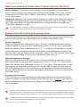
Humidification
The thermostat reads the indoor humidity level and allows the user to set a humidification setting with or without window protection.
Window Protection
Window Protection limits the amount of humidity to prevent frost or condensation on
windows. Window Protection (ISU 8050) requires an outdoor sensor.
The maximum humidity level that is allowed ("Window Limit") is displayed on the
Humidification Settings screen. The thermostat prevents frost or condensation on
windows by not allowing the humidity to go above the Window Limit when it is controlling the humidifier. This helps inform the user as to why their humidity setting
might not be reached at times. The Window
Limit is based on the current outdoor temperature and the user's window protection setting.
If Window Protection is turned Off, the thermostat controls the humidity level to the user's
desired humidity setting. Frost or condensation
may appear on windows.
To see all humidification options, press MENU > INSTALLER OPTIONS > VIEW/EDIT CURRENT SETUP >
HUMIDIFICATION.
Dehumidification - Residential
The thermostat reads the indoor humidity level and allows the user to set a dehumidification setting.
When set up for dehumidification using the cooling system, an overcooling limit can
be set from 0 F to 3 F (ISU 9070). The thermostat uses the cooling system to reduce
humidity by lowering the temperature up to 3 F below the current cool setpoint until
the desired humidity level is reached.
To see all dehumidification options, press MENU > INSTALLER OPTIONS > VIEW/EDIT CURRENT SETUP >
DEHUMIDIFICATION.
17
I/O-CHTSTAT03 69-2688—07
System Installation Guide
Dehumidification - Commercial
The thermostat reads the indoor humidity level and allows the user to set a
dehumidification setting.
Dehumidification using the cooling system has the following methods of
dehumidification control (ISU 9080):
Basic: This option uses the cooling system to reach the desired humidity level.
Minimum On Time and High Humidity Comfort Reset are not used with this method.
This option should only be used if the equipment can lower the fan speed in a call for
dehumidification.
Minimum on Time (ISU 9090): This option ensures that the compressor runs long
enough to effectively reduce humidity when the cooling equipment is cycled on. The
compressor will run for the minimum "on time" you set until the desired humidity level
is reached.
High Humidity Comfort Reset (ISU 9100): This option uses the cooling system
to lower the temperature up to 5 F below the current cool setpoint until the desired
humidity is reached. The high humidity comfort range is from 1 to 5 F.
High Humidity Comfort Reset with Minimum On Time (ISU 9090 and ISU
9100): This method uses both options above to reduce humidity while maintaining a
comfortable temperature.
To see all dehumidification options, press MENU > INSTALLER OPTIONS > VIEW/EDIT CURRENT SETUP >
DEHUMIDIFICATION.
69-2688—07 I/O-CHTSTAT03
18
CTK04 ComfortNet™ Communicating Thermostat
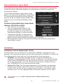
Dehumidification Away Mode
Dehumidification Away Mode protects the home when unoccupied for long periods
of time during hot and humid weather by maintaining the desired humidity and
temperature settings.
To start Dehumidification Away Mode, press
Menu, then press Dehumidification Away Mode.
The thermostat automatically follows settings
that are set by the dealer during installer setup.
Press Cancel to end Dehumidification Away
Mode.
Southern Dehumidification Away Mode
Options: (ISU 9180 to 9200)
• Fan: Auto, On or Circulate
• Low Limit Temperature Setting: The
thermostat allows the cooling system
to lower the indoor air to the Low Limit
Temperature Setting to control humidity.
• Temperature Setting: The temperature
maintained while Dehumidification Away
Mode is active and the desired humidity level is satisfied.
• Dehumidification Setting: The desired humidity level while Dehumidification
Away Mode is active.
Ventilation
Ventilation Control Method (ISU 10050)
The thermostat can control the fan to meet either ASHRAE or Percent On Time
settings. If the required ventilation has not been achieved for ASHRAE or Percent On
Time during calls for heat and cool, the thermostat will force the fan on.
• ASHRAE: The thermostat operates the fan to meet the ASHRAE 62.2
ventilation standard based on CFM, number of bedrooms, and square footage
of the house. ASHRAE 62.2 can only be met if the fan is running. If the fan is
off for any reason (set up to turn Off during Sleep period, turned off by user
etc.), ASHRAE 62.2 is not met during those times.
• Percent On Time: The thermostat operates the fan based on a percentage
entered in the installer setup (ISU 10120). For example, if Percent On Time
is set to 50%, the fan will run at random times during a 1 hour period until it
reaches a 50% run time (approximately 30 minutes). Options 10% to 100%.
To see all ventilation options, press MENU > INSTALLER OPTIONS > VIEW/EDIT CURRENT SETUP >
VENTILATION.
19
I/O-CHTSTAT03 69-2688—07
System Installation Guide
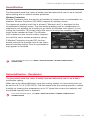
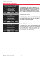
Indoor sensor operation
Temperature control
The thermostat can be set to respond to its
internal temperature sensor, or to an optional
remote indoor sensor. If multiple sensors are
used, the thermostat will respond to an average of temperatures detected at each sensor.
Humidification control
If optional remote indoor sensors are installed,
you can choose which sensor you want to use
for humidification control. You can use a different sensor for dehumidification.
Dehumidification control
If optional remote indoor sensors are installed,
you can choose which sensor you want to use
for dehumidification control. For example, you
can use one sensor for humidification control,
and another for dehumidification.
69-2688—07 I/O-CHTSTAT03
20
CTK04 ComfortNet™ Communicating Thermostat
Alerts Log
MENU > INSTALLER OPTIONS > DATA LOGS > ALERTS LOG
The thermostat saves the most recent 25 alerts. It records the date, time, alert status
(snoozed, dismissed, recovered), and diagnostic information to help you identify and
correct problems.
User Interactions Log
MENU > INSTALLER OPTIONS > DATA LOGS > USER INTERACTIONS LOG
Check this log to find out if a problem was caused by an accidental user error.
The log shows most changes made to thermostat settings, by time and date, and
describes what change was made.
The thermostat records the most recent 250 changes. You can quickly search them
by date and time, or by function. This feature can be turned off if necessary, so that
no user interactions are recorded.
Examples:
* [date, time] Heat temperature set to 80° F
* [date, time] System mode set to Off
* [date, time] Installer setup changed — heating equipment type
Replacing system components
Follow steps below to disconnect the thermostat and RedLINK accessories.
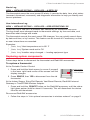
To replace a thermostat
At the Portable Comfort Control
1 Press and hold the blank space (or arrow if present)
in the lower right hand corner of the screen until the
display changes.
2 Press REMOVE, then YES to disconnect from the old
thermostat.
Press and hold
in lower right
corner of screen
MCR32958
At the Indoor Sensor, Entry/Exit Remote, Vent Boost Remote, RedLINK Internet
Gateway or TrueSTEAM Wireless Adapter
1 Press and hold the CONNECT button on the RedLINK accessory until the status
light glows amber (hold for about 10 seconds). This will disconnect the device
from the old thermostat.
Re-connect RedLINK accessories
1 Follow the steps in “Link optional accessories to wireless network” on page 9.
21
I/O-CHTSTAT03 69-2688—07
System Installation Guide
Replacing system components
To remove accessories from a thermostat
At the thermostat
1 Press MENU and scroll down to press INSTALLER OPTIONS. Enter the date
code (password) when prompted. The date code is printed on the back of the
thermostat; or press MENU > EQUIPMENT STATUS to find the date code.
2 After you enter the password, scroll down to select WIRELESS DEVICE MANAGER.
3 Press REMOVE DEVICE, then select the device you want to remove.
Specifications & replacement parts
Operating Ambient Temperature
Thermostat: 32 to 120° F (0 to 48.9° C)
Portable Comfort Control: 32 to 120° F (0 to 48.9° C)
Wireless Outdoor Sensor: -40 to 140° F (-40 to 60° C)
Wireless Indoor Sensor: 0 to 120° F (-17.8 to 48.9° C)
– For Optimal Battery Life: 35 to 114° F (1.7 to 45.6° C)
RedLINK Internet Gateway: 32 to 120° F (0 to 48.9° C)
Operating Relative Humidity
Thermostat: 5% to 90% (non-condensing)
Portable Comfort Control: 5% to 90% (non-condensing)
Wireless Outdoor Sensor: 0% to 100% (condensing)
Wireless Indoor Sensor: 5% to 90% (non-condensing)
RedLINK Internet Gateway: 5% to 95% (non-condensing)
Physical Dimensions (height, width, depth)
Thermostat: 3-7/8 x 6-13/16 x 1-7/16 inches (99 x 173 mm x 36 mm)
Wireless Outdoor Sensor: 5 x 3-1/2 x 1-11/16 inches (127 x 89 x 43 mm)
Wireless Indoor Sensor: 2-7/8 x 1-7/8 x 15/16 inches (74 x 48 x 24 mm)
Portable Comfort Control: 6-1/4 x 3-1/8 x 1-5/8 inches (158 x 80 x 38 mm)
RedLINK Internet Gateway: 6 x 4-7/8 x 2-1/2 inches (152 x 124 x 64 mm)
Electrical Ratings
18 to 30 VAC
Accessories & Replacement Parts
Item
RedLINK Internet Gateway
Entry/Exit Remote
Vent Boost Remote
Portable Comfort Control Wireless Outdoor Sensor Wireless Indoor Sensor Cover Plate (covers marks left by old thermostats) Battery Pack (For demo use only)
69-2688—07 I/O-CHTSTAT03
22
Honeywell Part Number
THM6000R1002
REM1000R1003
HVC20A1000
REM5000R1001
C7089R1013
C7189R1004
50028399-001
THP1000A1007
CTK04 ComfortNet™ Communicating Thermostat
Regulatory information
FCC Compliance Statement (Part 15.19) (USA only)
This device complies with Part 15 of the FCC Rules. Operation is subject to the following two conditions:
1 This device may not cause harmful interference, and
2 This device must accept any interference received, including interference that may cause undesired operation.
FCC Warning (Part 15.21) (USA only)
Changes or modifications not expressly approved by the party responsible for compliance could void the user’s authority to operate the
equipment.
FCC Interference Statement (Part 15.105 (b)) (USA only)
This equipment has been tested and found to comply with the limits for a Class B digital device, pursuant to Part 15 of the FCC Rules.
These limits are designed to provide reasonable protection against harmful interference in a residential installation. This equipment
generates uses and can radiate radio frequency energy and, if not installed and used in accordance with the instructions, may cause
harmful interference to radio communications. However, there is no guarantee that interference will not occur in a particular installation.
If this equipment does cause harmful interference to radio or television reception, which can be determined by turning the equipment off
and on, the user is encouraged to try to correct the interference by one of the following measures:
• Reorient or relocate the receiving antenna.
• Increase the separation between the equipment and receiver.
• Connect the equipment into an outlet on a circuit different from that to which the receiver is connected.
• Consult the dealer or an experienced radio/TV technician for help.
Thermostats and outdoor sensor
To comply with FCC and Industry Canada RF exposure limits for general population/ uncontrolled exposure, the antenna(s) used for
these transmitters must be installed to provide a separation distance of at least 20 cm from all persons and must not be co-located or
operating in conjunction with any other antenna or transmitter.
Portable Comfort Control
This portable transmitter with its antenna complies with FCC and Industry Canada RF exposure limits for general population/
uncontrolled exposure. This device must not be co-located or operating in conjunction with any other antenna or transmitter.
Section 7.1.2 of RSS-GEN
Under Industry Canada regulations, this radio transmitter may only operate using an antenna of type and maximum (or lesser)
gain approved for the transmitter by Industry Canada. To reduce potential radio interference to other users, the antenna type and
its gain should be so chosen that the equivalent isotropically radiated power (e.i.r.p.) is not more than that necessary for successful
communication.
Section 7.1.3 of RSS-GEN
Operation is subject to the following two conditions:
1 this device may not cause interference, and
2 this device must accept any interference, including interference that may cause undesired operation of the device.
23
I/O-CHTSTAT03 69-2688—07
Need Help?
For assistance please visit www.ComfortNet1.com, or call toll-free: (888) 593-9988
Honeywell International Inc.
1985 Douglas Drive North
Golden Valley, MN 55422
http://customer.honeywell.com
® U.S. Registered Trademark. © 2014 Honeywell International Inc.
69-2688—07 M.S. Rev. 01-14
I/O-CHTSTAT03
Printed in U.S.A.
Goodman Manufacturing Co., LP
Suite 500
5151 San Felipe
Houston, TX 77056